Installation and Operation Manual for VMAC Accessory · Installation and Operation Manual for VMAC...
24
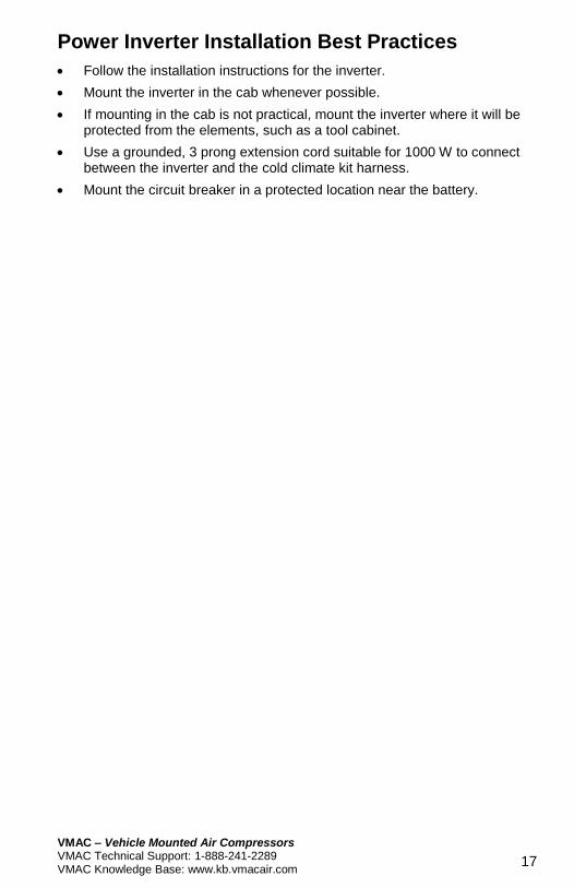
Installation and Operation Manual for VMAC Accessory A500044 / A520004 Cold Climate Kit
Transcript of Installation and Operation Manual for VMAC Accessory · Installation and Operation Manual for VMAC...

Installation and Operation Manual for VMAC
Accessory A500044 / A520004
Cold Climate Kit


VMAC – Vehicle Mounted Air Compressors VMAC Technical Support: 1-888-241-2289 VMAC Knowledge Base: www.kb.vmacair.com
1
Installation / Operation Manual for VMAC Accessory A500044 / A520002
Cold climate kit
Safety .......................................................................................................3 Warranty ..................................................................................................4 General Information ................................................................................5 Illustrated Parts List ...............................................................................6 General Safety Precautions ...................................................................7 Maintenance and Repair Safety .............................................................8 Installation ...............................................................................................9 Operation .................................................................................................18

VMAC – Vehicle Mounted Air Compressors VMAC Technical Support: 1-888-241-2289
VMAC Knowledge Base: www.kb.vmacair.com 2
Document: 1901064 Changes and Revisions
Additional Application Information • For use with VMAC G300003, Gas Engine Driven 30 CFM Air
Compressor.
• Requires 600 W power inverter (VMAC P/N: A500181). Sold separately.
Registered Trademarks All trademarks mentioned in this manual are the property of their respective owners. VMAC’s use of manufacturers’ trademarks in this manual is for identification of the products only and does not imply any affiliation to, or endorsement of said companies.
Loctite® and Loctite® 242 are registered trademarks of Henkel AG & Company KGaA.
Permatex® and Ultra Black® are registered trademarks of ILLINOIS TOOL
WORKS INC.
Important Information The information in this manual is intended for certified VMAC installers who have been trained in installation procedures and/or for people with mechanical trade certification who have the tools and equipment to properly and safely perform the installation. Do not attempt this installation without the appropriate mechanical training, knowledge and experience.
Follow all safety precautions for mechanical work. Any fabrication for correct fit in modified vehicles must follow industry standard “best practices”.
Notice Copyright © 2017 VMAC Global Technology Inc. All Rights Reserved. These materials are provided by VMAC for informational purposes only, without representation or warranty of any kind, and VMAC shall not be liable for errors or omissions with respect to the materials. The only warranties for VMAC products and services are those set forth in the express warranty statements accompanying such products and services, if any, and nothing herein shall be construed as constituting an additional warranty. Printing or copying of any page in this document in whole or in part is only permitted for personal use. All other use, copying or reproduction in both print and electronic form of any part of this document without the written consent of VMAC is prohibited. The information contained herein may be changed without prior notice.
Printed in Canada
Revision Revision Details Revised
by
Checked by
Implemented Eng. Tech. Qual.
Mech. Elec.
A Initial Release MSP MRH N/A GB AMG 25 July 2017
KEEP THIS MANUAL WITH THE GAS ENGINE DRIVEN 30 CFM COMPRESSOR
UNIT FOR USER REFERENCE

VMAC – Vehicle Mounted Air Compressors VMAC Technical Support: 1-888-241-2289 VMAC Knowledge Base: www.kb.vmacair.com
3
Safety
Important Safety Notice The information contained in this manual is based on sound engineering principles, research, extensive field experience and technical information. Information is constantly changing with the addition of new models, assemblies, service techniques and running OEM changes. If a discrepancy is found in this manual, contact VMAC prior to initiating or proceeding with installation, service or repair. Current information may clarify the issue. Any person with knowledge of such discrepancies, who proceeds to perform service and repair assumes all risks.
Only proven service procedures are recommended. Anyone who departs from the specific instructions provided in this manual must first assure that their safety and that of others is not being compromised and that there will be no adverse effects on the operational safety or performance of the equipment.
VMAC will not be held responsible for any liability, consequential damages, injuries, loss or damage to individuals or to equipment as a result of the failure of any person to properly adhere to the procedures set out in this manual or standard safety practices. Safety should be the first consideration when performing any service operations. If there are any questions concerning the procedures in this manual or more information is required, please contact VMAC before beginning repairs.
Safety Messages This manual contains various warnings, cautions and notices that must be observed to reduce the risk of personal injury during installation, service or repair and the possibility that improper installation, service or repair may damage the equipment or render it unsafe.
This symbol is used to call attention to instructions concerning personal safety. Watch for this symbol; it points out important safety precautions, it means, “Attention, become alert! Your personal safety is involved”. Read the message that follows and be aware of the possibility of personal injury or death. As it is impossible to warn of every conceivable hazard, common sense and industry standard safety practices must be observed.
This symbol is used to call attention to instructions on a specific procedure that if not followed may damage or reduce the useful life of the compressor or other equipment.
This symbol is used to call attention to additional instructions or special emphasis on a specific procedure.

VMAC – Vehicle Mounted Air Compressors VMAC Technical Support: 1-888-241-2289
VMAC Knowledge Base: www.kb.vmacair.com 4
Warranty
VMAC Standard Warranty (Limited) For complete warranty information, including both VMAC Standard Warranty (Limited) and VMAC Lifetime Warranty (Limited) requirements, please refer to our current published warranty located at:
www.vmacair.com/warranty If you do not have access to a computer, please contact us and we will be happy to send you our warranty.
VMAC’s warranty is subject to change without notice.
VMAC Lifetime Warranty (Limited) A VMAC Lifetime Limited Warranty is
offered on the base air compressor
only and only on UNDERHOOD,
Hydraulic Driven, Transmission
Mounted, Gas and Diesel Engine
Driven Air Compressors,
Multifunction Power Systems, and
other products as defined by VMAC,
provided that (i) the purchaser fully
completes and submits a warranty registration form within 3 months of
purchase, or 200 hours of operation, whichever occurs first; (ii) services are
completed in accordance with the Owner’s Manual; (iii) proof of purchase of
applicable service kits are made available to VMAC upon request.
The VMAC Lifetime Warranty is applicable to new products shipped on or after 1 October, 2015.
Warranty Registration The VMAC warranty registration form is located near the back of this manual. This warranty registration form must be completed and sent to VMAC at the time of installation for any subsequent warranty claim to be considered valid.
There are 4 ways the warranty can be registered with VMAC:
Online www.vmacair.com/warranty
Email [email protected]
Fax (250) 740-3201
Mail VMAC - Vehicle Mounted Air Compressors 1333 Kipp Road, Nanaimo, BC, Canada V9X 1R3

VMAC – Vehicle Mounted Air Compressors VMAC Technical Support: 1-888-241-2289 VMAC Knowledge Base: www.kb.vmacair.com
5
General Information
Before Starting Read this manual prior to installing or operating the Cold Climate Kit onto the
Gas Engine Driven 30 CFM Air Compressor to ensure familiarity with the
components, installation requirements and how to operate the unit.
Open the package, unpack the components and identify them using the
included IPL on page 6.
Ordering Parts To order parts, contact a VMAC dealer. The dealer will ask for the VMAC serial number, part number, description and quantity. Locate the nearest dealer online at www.vmacair.com/dealer-locator or call 1-877-912-6605.
Torque Specifications All fasteners must be torqued to specifications. Use manufacturers’ torque
values for OEM fasteners. Apply Loctite 242 (blue) or equivalent on all
engine mounted fasteners. Torque values are with Loctite applied unless
otherwise specified.
STANDARD GRADE 8 NATIONAL COARSE THREAD
Size 1/4 5/16 3/8 7/16 1/2 9/16 5/8 3/4
Foot-pounds (ft•lb) 9 18 35 55 80 110 170 280
Newton meter (N•m) 12 24 47 74 108 149 230 379
STANDARD GRADE 8 NATIONAL FINE THREAD
Size 3/8 7/16 1/2 5/8 3/4
Foot-pounds (ft•lb) 40 60 90 180 320
Newton meter (N•m) 54 81 122 244 434
METRIC CLASS 10.9
Size M6 M8 M10 M12 M14 M16
Foot-pounds (ft•lb) 4.5 19 41 69 104 174
Newton meter (N•m) 6 25 55 93 141 236
Table 1 – Torque Table

VMAC – Vehicle Mounted Air Compressors VMAC Technical Support: 1-888-241-2289
VMAC Knowledge Base: www.kb.vmacair.com
6
Illustrated Parts List
Item QTY Part # Description
1 1 3200535 HEATER BLOCK, G30
2 1 3550978 HARNESS, G30 HONDA, COLD CLIMATE
3 1 3550934 HEATER, 200W, ASSY
4 1 3550935 HEATER, 400W, ASSY
5 1 1901064 INSTR, COLD CLIMATE KIT, G300003
6 2 2200251 HOSE CLAMP, 3/8, ZINC
7 2 2200202 CLAMP, STRAP 7/8
8 4 2200019 TIE, NYLON MD, 6"
9 2 1500711 CLIP, 1/4 ID, ROUTING
10 1 5240318 SEALANT, RTV HIGH TEMP, ULTRA 80ML
(Only included with A500044)

VMAC – Vehicle Mounted Air Compressors VMAC Technical Support: 1-888-241-2289 VMAC Knowledge Base: www.kb.vmacair.com
7
General Safety Precautions
Moving Parts Hazard • Before performing any service, disconnect the
negative battery cable and the spark plug wire to prevent the engine from starting unexpectedly
• Do not operate the compressor without the guards in place. If the guards are damaged or missing, replace them before operating the equipment.
Burn Hazard • The engine, exhaust and the compressor system get
very hot during operation, contact with the components or the oil may cause serious injury. Allow sufficient time for the system to cool before performing service.
• Never allow any body parts to contact the engine or compressor components while they are hot.
General Warnings • Disconnect the spark plug wire before attempting
any repair or service.
• Be attentive for unexplained changes in operation parameters and record any changes.
• Check the compressor oil level and condition before starting the system. Do not add or change oil while the system is running. Use only approved oil.
• The compressor operates anytime the engine is running. Avoid contact with the compressor, hoses, or engine during operation.
• Keep hoses and wiring away from hot, sharp, or moving components.
• Use only approved hoses and replacement parts.
• Do not modify the equipment.
• Do not operate the air compressor when fatigued or under the influence of alcohol or drugs.
• Know how to operate the compressor, fully read the manual.
• Check equipment before every use.
• Never bypass or disable any of the safety equipment.
• Never adjust or attempt to make any repairs to the compressor system while the engine is running. Components and hoses under pressure could fail and cause serious injury or death.

VMAC – Vehicle Mounted Air Compressors VMAC Technical Support: 1-888-241-2289
VMAC Knowledge Base: www.kb.vmacair.com
8
Maintenance and Repair Safety
It is impossible to warn of all the possible hazards that may
result from operating, servicing, or repairing this system.
Wear all appropriate Personal Protective Equipment and
follow all industry standard safety practices.
Confirm that the system is depressurized and has cooled
prior to performing any service work.
Never use flammable solvents to clean any components. If a
flammable solvent has been used, rinse the component
thoroughly with water and dry it before reinstalling it to
prevent the possibility of explosion.
Use only genuine VMAC replacement parts to maintain the
system.
Genuine VMAC replacement parts are designed to work with
the high pressure and heat generated by the compressor.
Substituting genuine VMAC replacement parts will void the
warranty and could fail causing equipment damage, injury, or
death.
This information is intended for people with mechanical
trade certification who have the tools and equipment to
properly and safely perform the service or repair. Do not
attempt to service or repair this system without the
appropriate mechanical training, knowledge and experience.
Follow all safety precautions and industry standard “best
practices”.
The negative battery cable and spark plug wire must be
disconnected prior to performing any service or repair work.
Failure to perform this step may result in the engine starting
unexpectedly if the crankshaft is rotated.
Only reconnect the battery cable and spark plug wire once
service or repair has been completed.

VMAC – Vehicle Mounted Air Compressors VMAC Technical Support: 1-888-241-2289 VMAC Knowledge Base: www.kb.vmacair.com
9
Installation
Apply Loctite 242 or equivalent on all engine mounted
fasteners.
Heater Cartridge Installation Ensure the system is cool, and the ignition key switch is in the “OFF”
position.
Disconnect the negative battery cable.
Disconnect the spark plug wire (Figure 1).
Figure 1 – Spark plug wire
Ensure the 200 W heater cartridge (P/N: 3550934) is installed into the compressor.
Insert the 200 W heater cartridge into the compressor. Ensure the
cartridge protrudes no more than 1/8 in from the casting (Figure 2).
Figure 2 – Install compressor heater
(Shroud removed for clarity)
1/8 in or less protruding

VMAC – Vehicle Mounted Air Compressors VMAC Technical Support: 1-888-241-2289
VMAC Knowledge Base: www.kb.vmacair.com
10
Fill the cavity in the compressor with the supplied RTV sealant to secure
the heater cartridge in place (Figure 3).
Figure 3 – Secure heater cartridge
Remove the 2 engine mounting fasteners and 1 engine shroud fastener;
these fasteners will be reused (Figure 4).
Figure 4 – Engine mount fasteners
Ensure the 400 W heater cartridge (P/N: 3550935) is installed into the heater block.
Insert the 400 W heater cartridge into the heater block and secure it with
the (2x) 3/8 in hose clamps (Figure 5).
Figure 5 – Engine heater cartridge
Fill cavity with RTV sealant

VMAC – Vehicle Mounted Air Compressors VMAC Technical Support: 1-888-241-2289 VMAC Knowledge Base: www.kb.vmacair.com
11
Install the heater block and cartridge using the 2 engine mounting
fasteners removed earlier (Figure 6).
Figure 6 – Install engine heater block
Route the cold climate harness between the engine and the PTFE tube
connected to the throttle actuator (Figure 7).
Figure 7 – Routing the harness
PTFE tube

VMAC – Vehicle Mounted Air Compressors VMAC Technical Support: 1-888-241-2289
VMAC Knowledge Base: www.kb.vmacair.com
12
Route the harness under the hour meter cable and through the relief in
the engine brace that the hour meter is mounted to (Figure 8).
Figure 8 – Routing the harness
Secure the ground wire terminal to the engine block using the engine
shroud fastener removed earlier. Orient the ground wire upward so that it
follows the contour of the shroud, then over toward the outside of the unit
(Figure 9).
Figure 9 – Connect ground wire
Route harness through relief
Hour meter cable

VMAC – Vehicle Mounted Air Compressors VMAC Technical Support: 1-888-241-2289 VMAC Knowledge Base: www.kb.vmacair.com
13
Route the engine heater harness under the ground cable and toward the
recoil pull start (Figure 10).
Figure 10 – Route the heater cable
Connect the engine heater harness to the cold climate harness
(Figure 11).
Figure 11 – Connect engine heater
Route harness under ground
wire
Ground wire
Connect harness

VMAC – Vehicle Mounted Air Compressors VMAC Technical Support: 1-888-241-2289
VMAC Knowledge Base: www.kb.vmacair.com
14
Gently pull the cold climate harness toward the WHASP Tank to remove
any slack. Install the loom clip and P-clip and secure the harness (Figure 12).
Figure 12 – Secure the harness
Secure the harness to the P-clip using 2 of the supplied cable ties
(Figure 13).
Figure 13 – Secure the harness
Secure heater cable
Secure cold climate harness
Secure harness to P-clip

VMAC – Vehicle Mounted Air Compressors VMAC Technical Support: 1-888-241-2289 VMAC Knowledge Base: www.kb.vmacair.com
15
Secure the engine heater cartridge connector to the cold climate harness
(Figure 14).
Figure 14 – Secure connector to harness
Route the cold climate harness up behind the discharge valve and secure
it to the compressor brace using supplied loom clip (Figure 15).
Figure 15 – Route cold climate harness
Route harness behind discharge valve
Secure connector to harness
Supplied loom clip

VMAC – Vehicle Mounted Air Compressors VMAC Technical Support: 1-888-241-2289
VMAC Knowledge Base: www.kb.vmacair.com
16
Connect the compressor heater cartridge to the cold climate harness
(Figure 16).
Figure 16 – Connect compressor heater
Connect the compressor heater harness to the PTFE tube connected to
the air bleed muffler using one of the supplied cable ties (Figure 17).
Figure 17 – Secure the harness
Connect harness
Leave approximately 1 in slack in harness
Air bleed PTFE tube
Secure harness
VMAC – Vehicle Mounted Air Compressors VMAC Technical Support: 1-888-241-2289 VMAC Knowledge Base: www.kb.vmacair.com
17
Power Inverter Installation Best Practices
• Follow the installation instructions for the inverter.
• Mount the inverter in the cab whenever possible.
• If mounting in the cab is not practical, mount the inverter where it will be protected from the elements, such as a tool cabinet.
• Use a grounded, 3 prong extension cord suitable for 1000 W to connect between the inverter and the cold climate kit harness.
• Mount the circuit breaker in a protected location near the battery.

VMAC – Vehicle Mounted Air Compressors VMAC Technical Support: 1-888-241-2289
VMAC Knowledge Base: www.kb.vmacair.com
18
Operation
VMAC recommends using an inverter rated for a minimum of
600 W continuous power.
VMAC is unable to provide specific warming times as variations in air
temperature and Gas Engine Driven 30 CFM Air Compressor mounting
locations will affect the time it takes to warm the compressor system.
The heaters may need to be on for 30 minutes or more prior to starting the
engine to allow sufficient time for the system to warm up; this can generally
be accomplished while driving to work.
Ensure the vehicle engine is running while the cold climate kit is enabled
as the inverter’s current draw is capable of draining the batteries quite
rapidly.
Turn the inverter switch on.
Once the system has warmed sufficiently turn the inverter off.
If operating the Gas Engine Driven 30 CFM Air Compressor in extreme
temperatures, special considerations may be required.
The Gas Engine Driven 30 CFM Air Compressor cold climate kit
is not equipped with a timer or automatic shut off. Once the
unit has warmed up, turn off or unplug the inverter;
alternatively, the cold climate kit can be connected to a switch
allowing the heaters to be turned off while the inverter supplies
power

This page intentionally left blank

This page intentionally left blank


![PRE-AUTH COMPLETION CORRECTION (VOID) REPORTS & …LAST RECEIPT ANY RECEIPT TIME PURCHASE REFUND SETTLEMENT CORRECTION 1 1 VMAC DATE TIME CommServer SOFTPAY-FDCC [OPTIONAL] VMAC TE](https://static.fdocuments.in/doc/165x107/5f30baf6f93ef7490870590f/pre-auth-completion-correction-void-reports-last-receipt-any-receipt-time.jpg)