INSTALLATION AND OPERATION MANUAL ENVIRONMENTAL SYSTEM · PDF fileINSTALLATION AND OPERATION...
22
INSTALLATION AND OPERATION MANUAL ENVIRONMENTAL SYSTEM IR-SNIF MODELS SNIF-1A, 4A, 8A SenTech Corporation 5745 Progress Road Indianapolis, Indiana 46241 888/248-1988 FAX 317/248-2014 REFRIGERANT MONITOR SenTech RESET LOW MAIN HIGH PROGRAMMING IR-SNIF 3 FRESH AIR 4 2 1 EXHAUST ALARMS
Transcript of INSTALLATION AND OPERATION MANUAL ENVIRONMENTAL SYSTEM · PDF fileINSTALLATION AND OPERATION...
INSTALLATION AND OPERATION MANUALENVIRONMENTAL SYSTEM IR-SNIF
MODELS SNIF-1A, 4A, 8A
SenTech Corporation5745 Progress RoadIndianapolis, Indiana 46241888/248-1988FAX 317/248-2014
REFRIGERANT MONITOR
SenTech
RESET
LOW
MAIN
HIGH
PROGRAMMING
IR-SNIF
3
FRESH AIR4
2
1
EXHAUST
ALARMS

Contents
SAFETY PRECAUTIONS and WARNINGS ....................................................................................................................... 3SPECIFICATIONS ............................................................................................................................................................. 4INTRODUCTION/OVERVIEW ............................................................................................................................................ 5 Basic Concept .......................................................................................................................................................... 5 Sensitivity ................................................................................................................................................................ 5
INSTALLATION ................................................................................................................................................................. 6 Location .................................................................................................................................................................... 6 Mounting and Tuging Installation ............................................................................................................................... 6 Primary Power ........................................................................................................................................................... 6
OPTIONAL CONNECTIONS .............................................................................................................................................. 8 Alarm Relay Contacts .............................................................................................................................................. 8 Analog Outputs ........................................................................................................................................................ 8
START-UP ......................................................................................................................................................................... 8 Setup ....................................................................................................................................................................... 8 Final Check .............................................................................................................................................................. 9
SYSTEM OPERATION .................................................................................................................................................... 10
PREVENTIVE MAINTENANCE ....................................................................................................................................... 11
APPENDIX A ................................................................................................................................................................... 12 Programming and Operator Interface ...................................................................................................................... 12
APPENDIX B ................................................................................................................................................................... 15 Room Volume Considerations (English) .................................................................................................................. 15 Room Volume Considerations (Metric) .................................................................................................................... 16
EXPLODED VIEW & PARTS LIST .................................................................................................................................. 17
WIRING DIAGRAM .......................................................................................................................................................... 18
TROUBLESHOOTING GUIDE ......................................................................................................................................... 19
WARRANTY .................................................................................................................................................................... 21
ILLUSTRATIONS Fig. 1 Block Diagram ............................................................................................................................................... 5 Fig. 2 Primary Power Wiring Diagram ...................................................................................................................... 6 Installation Layout .................................................................................................................................................... 7 Fig. 3 Alarm Relay Option Wiring............................................................................................................................. 8 Fig. 4 Analog Output ............................................................................................................................................... 8 Fig. 5 Front Panel .................................................................................................................................................. 10
- 2 -

SAFETY PRECAUTIONS and WARNINGS
The following general safety precaustions and warnings must be observed during all phases of installation, operation,service and repair of the equipment. Failure to comply with these precautions, given here and elsewhere in the manualviolates safety standards of design, manufacture. and intended use. SenTech assumes no liability for the customer'sfailure to comply with these requirements.
Definitions of safety symbols used on equipment and in manuals.
AC Voltage Terminal: Indicates areas of the equipment where AC line voltages are used and present apotential risk of electrocution. Areas using line voltages should not be accessed during operation.
Protective Grounding Terminal:The protective ground is to prevent electric shock in case of an electricalfualt. This symbol indicates that the terminal must be connected to earth or ground before operation of theequipment.
CAUTION!Caution: This sign calls attention to a procedure or practicewhich if not adhered to could result in damage or destruction toa part of the product.
Input Power: Power should be supplied through a two pole circuit breaker located in reasonable proximity to theequipment. Ensure that the voltages are correct and an appropriate ground connection is provided.
Installation, Maintenance, and Repair: These functions should only be done by qualified personnel following theinstructions outlined in this manual. This is Installation Catagory III equipment.
Pollution Degree: This equipment is designed for a Pollution Degree of 1.
Cleaning: The equipment should be cleaned by wiping with a soft clean cloth.
Intended Purpose: This equipment is designed to be used as a continuous refrigerant monitor. It should not be usedfor any other purpose.
- 3 -

- 4 -
Models SNIF-1A, 4A, 8A Specifications
Size: 16 1/2" X 15" X 6 3/4"(42 cm X 38.1 cm X 17 cm)
Weight: 30 lbs(13 kgs)
Power: 120/240 Volt (+/- 10%) 50/60 Hz (41 Watts)
Temperature: 32°- 125° Fahrenheit, (0°- 50° Centigrade)Humidity: 0 - 95% non-condensingAtmospheric: 75 - 106 KPaPressure
Equipment rated for indoor use only
Range: 0 - 1000 P.P.M. Standard
Tube Length 0-250 ft. (76 meters)
Rezeroing Automatic Standard
Zones Model SNIF-1A - 1Model SNIF-4A - 1 to 4 ProgrammableModel SNIF-8A - 1 to 8 Programmable
Trip Point: Low Alarm 0 -100% of Full ScaleMain Alarm 0 - 100% of Full ScaleHigh Alarm 0 -100% of Full Scale
Leak Wait: Varies from seven (7) seconds tothree (3) minutes depending onrefrigerant concentration
Alarm Output: Low, Main, and High Alarm RelaysFour (4) form C contacts rated 5 amps maximum
Analog Out: 0 to 10 VDC Standard4 - 20 ma Optional

- 5 -
Fig. 1System Block Diagram
INTRODUCTION/OVERVIEW
The SenTech Environmental System IR-SNIF, Models SNIF-1A, 4A, and 8A provide an early warning of developing refrigerantleaks. The unit sequentially samples the ambient air in each selected zone and measures the amount of halogen basedrefrigerant gas in the air sample. When the proportion of refrigerant present exceeds a trip point, the system goes into AlarmMode notifying the user. By discovering a leak shortly after it starts, the potential loss can be reduced to ounces of refrigerantsaving money and helping protect the environment.
Basic ConceptRefer to the Block Diagram, (Fig. 1). Tubing from eacharea to be monitored is connected to the input manifold.The electronics sequentially energize the solenoid valvesfor each zone. The diaphragm pump draws air from theselected zone through the 5 micron filter assembly, theorifice, the infrared bench, and then to the exhaust port.The solid arrows show the air flow for normal operation.
The Infrared Bench has a source of IR energy at one endand a filter/detector at the other. Refrigerant present in thesample air will cause a decrease in the output of thedetector. This change in signal is analyzed by theelectronics and converted into a digital PPM (parts permillion) level. The PPM level is compared to the trip pointsfor that zone. If the PPM exceeds the Low Trip point, theLow Alarm Relay will be energized. If the signal continuesto increase, the Main Alarm will be energized and ulti-mately the High Alarm. Once the system enters Low, Mainor High Alarm for any zone, it will remain in that mode untilthe problem is cleared and the system is Reset.
SensitivityThe system is sensitive in varying amounts, to all of thehalogen based refrigerants, those that contain molecules
of either fluorine, chlorine or both. As part of the setup, thespecific refrigerant to be monitored by each zone is enteredinto the system. The computer control compensates for thediffering sensitivities, resulting in a true PPM reading forthe refrigerant in the zone being tested.
The IR-SNIF system maintains accuracy through its auto-matic rezeroing capability. Periodically, the systemswitches to the Fresh Air inlet, and reestablishes itsbaseline level.
There is no direct relationship between the amount ofrefrigerant leaking and the concentration level being mea-sured. The size of the room, the location of the pick up pointrelative to the leak point, and the air pattern, all will affectthe actual concentration at the inlet. However, by judiciouslocation of the inlets (see installation section) and maintain-ing the trip point at a level not too far above the ambient,leaks should be detected substantially before they other-wise would be noticed. See Appendix B for a detaileddiscussion of room volume considerations.
PNEUMATICSELECTRONICS
PRESSURE SWITCH
ORIFICE
DIAPHRAGM PUMP
INFRARED BENCH
INPUTMANIFOLD
(4 ZONEEXAMPLE)
ZONES
1
2
3
4
FRESH AIR
EXHAUST FILTERASSEMBLYRELAYS
VALVESOUTPUTS
MMB
LIGHTS & PB
KEYPAD
DISPLAY
COMPUTER CONTROL
INSTALLATION
Material RequiredPacked with the system:1. This manual.
2. The coarse tube end filters.
3. The CTS/Warranty card which is to be completed andreturned after start-up.
User supplied or optionally purchased.1. Plastic tubing 1/4" OD for the remote pickup points andfresh air inlet.
2. Horns, lights or other warning devices.
3. Wire for primary power and alarm devices.
(Refer to the Series IR-SNIF Installation Layout on page 7for an overview of installation requirements.)
LocationSince the monitor measures the concentration of refrigerantin air, each zone pick up point should be mounted where itis most likely to sense leaking refrigerant. The criteria toconsider in selecting a location include:
1. As close to the area of potential leaks as possible. Onthe "downstream" side of the air flow pattern in the room.
2. Since refrigerants are typically heavier than air, the pickup tubes should be terminated 20" (50 cm.) above thefloor.
3. The control unit should be located such that the farthestpick up point will require no more than 250 feet (75meters) of tubing. The Fresh Air inlet tubing can belonger if required.
4. The Monitor includes electronics and an infrared bench,the mounting point should be free from vibration to theextent practical.
CAUTION!
MOISTURE CAN DAMAGE THE INFRAREDBENCH. PICK UP POINTS AND THE FRESHAIR INLET MUST BE LOCATED AND PRO-TECTED WHERE NECESSARY TO PRE-VENT WATER FROM ENTERING THE SYS-TEM.
Mounting and Tubing InstallationDrill the necessary holes and mount the unit.
Zone Pick Up TubesInstall the 1/4" tubing from each zone pick up point to thezone inlet fittings on the right side of the control unit. It isrecommended that you start with zone 1 at the top, and
- 6 -
continue in sequence until the tube for each zone is installed.Terminate the tubing with the coarse filters.
Fresh Air Pick Up TubeSince the fresh air input is the means by which the systemmaintains it's accuracy, it must be located at a point thatcannot be reached by any leaking refrigerant. Install thetube for fresh air from the Fresh Air inlet at the bottom of theinput manifold to a point outside the area being monitored.Terminate the tube with its coarse filter.
Suggested locations are:
An adjacent room, hallway, or office
Up into an air inlet duct
Outside the building(As long as you are very careful to protect it from rain orrain splash. Water will damage the infrared bench.)
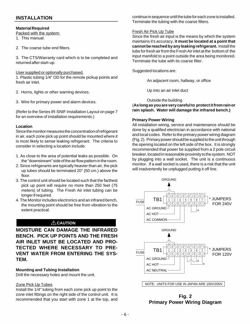
Primary Power WiringAll installation wiring, service and maintenance should bedone by a qualified electrician in accordance with nationaland local codes. Refer to the primary power wiring diagram(Fig. 2). Primary power should be supplied to the unit throughthe opening located on the left side of the box. It is stronglyrecommended that power be supplied from a 2 pole circuitbreaker, located in reasonable proximity to the system. NOTby plugging into a wall socket. The unit is a continuousmonitor. If a wall socket is used, there is a risk that the unitwill inadvertently be unplugged putting it off line.
1 2 3 4 5 6 7 * JUMPERS FOR 120V
AC NEUTRAL
AC HOT
AC GROUND*
*
FUSE
GROUND
1 2 3 4 5 6 7 * JUMPERS FOR 240V
AC COMMON
AC HOT
AC GROUND*
FUSE
GROUND
NOTE: UNITS FOR USE IN JAPAN ARE 100V/200V.
TB1
TB1
Fig. 2Primary Power Wiring Diagram

- 7 -
Item Description Required SuppliedwithUnit
Suppliedby
Customer
Optional Availablefrom
SenTech
Comments
1
2
3
4
5
6
7
8
16 Gauge, 3 Conductor Cable
18 or 22 Gauge, 2 Conductor Cable
2 Conductor Twisted Pair Shielded Cable
Horn
Strobe Light
Combination Horn and Strobe
1/4" OD X 1/8" ID Plastic Tubing (recommend flame retardant, smoke resistant)
Coarse Filter
yes
no
no
no
no
no
yes
yes
no
yes
no
yes
yes
yes
yes
yes
yes
no
no
yes
yes
yes
yes
Required for horn, strobe or combination
Required for remote analog output
Available in 250 foot reels
4 5 6
Horn Strobe Horn/StrobeCombination
3
RemoteAnalogOutput
115/230VAC 50/ 60HZ
SINGLE PHASEAC Power
1
2
2
*Intake Point#1
*Intake Point#2
*Moisture can damage the sensor.Pick-up points must be located and protected where necessary to preventwater from entering the system.
no
For mounting at theend of the tubing
7
8
SERIES SNIF-IR INSTALLATION LAYOUT
2
Alarm RelayContacts
REFRIGERANT MONITOR
SenTech
RESET
LOW
MAIN
HIGH
PROGRAMMING
SNIF-IR
3
FRESH AIR4
2
1
EXHAUST
7
8Fresh
AirThe Fresh Air pickup point must be located where thereis no refrigerant present
7
8
Model SNIF-04Awith 2 zones in use
ALARMS

- 8 -
OPTIONAL CONNECTIONS
Alarm Relay ContactsWarning lights, horns or other devices are actuated usingthe Alarm relay contacts on TB2 as shown (Fig. 3). Use anauxiliary contactor for heavy loads such as exhaust fans.Note: alarm contacts are rated (5) amps/240 VACmaximum. (Refer to the system wiring diagram for aschematic of the alarm relays.)
Fig. 3Alarm Relay Option Wiring
Analog OutputsFor the following discussion refer to Fig. 4 Analog Outputs.
0-10 Volt DC Analog OutputThe 0-10 Volt DC analog output is available at TB-3 (FIG.4). Terminal 1 is the positive side of the output and terminal3 is the common or negative side of the output.
4-20ma Output (Optional)If the 4-20ma option has been purchased, the output isavailable at terminals 2 and 3 of TB3. Terminal 2 is the pluscurrent output and terminal 3 is the common.
0-10 VDC PLUS
TB-3
ANALOG OUT COMMON
1 2 3 4 5 6 7
4-20MA PLUS
Fig. 4Analog Out
STARTUP
BEFORE PROCEEDING DOUBLE CHECKYOUR WIRING
Apply power to the monitor. The unit will now go through itsnormal startup checks and warmup procedure. approxi-mately9 minutes
(If during startup a fault condition is detected, follow theinstructions on the screen, and refer to the troubleshooting section of this manual.)
At the completion of warmup, the unit will be in AutomaticMode monitoring the first zone. The monitor will now beoperating under the default settings it had when it left thefactory. These may or may not be optimal for this installa-tion.
SETUPThe Setup procedures will allow you to select the followingparameters for each zone:
1. Zone on or off: For multizone systems, you should turn offzones that are not in use to avoid wasting time in those zones.
2. Refrigerant: The setup screens will provide gas codes for thevarious refrigerants.
3. Tube Length: You can optimize the amount of time spent ineach zone by entering the approximate length of tubing usedfor that zone. For single zone units, it is recommended thatthe tube length be set for 100 feet.
4. Low Alarm Level: This will set the PPM level for a Low Alarmcondition for that zone.
5. Main Alarm Level: This sets the trip point for Main Alarm.
6. High Alarm Level: This sets the trip point for High Alarm. Itis recommended that this trip point be set at or near full scale.
Before proceeding with the Setup, it is a good idea to review andmake notes on your intended settings for each zone. A rough "ballpark" approximation is more than adequate for tube length.
The display will provide step by step instructions for the Setupprocedure. (For a detailed description of the procedures, turn tothe section on Programming and Operator Interface.)
Enter "#" to exit Automatic.Enter "4" for SetupEnter "999" and then "#" to access the entry screenEnter "4" for setup
Follow the instructions for determining gas codes, selectingthe zones you want active, and setting up each zone.
After you have completed setting up all the zones you willuse, and turning off the unused zones, exit back to theAutomatic Mode, for the final system checks.
8765
4321
14G13
1211109
ALARM RELAY
1 2 3 4 5 6 7
5 59 9 95
LOWALARM
MAINALARM
HIGHALARM
ADDITONALCONTACTSAVAILABLE
ON PINS6 & 107 & 118 & 12
USER CONNECTIONS
TB2

FINAL CHECKSAt this point, the system should have all the zones Setup,and it should be monitoring the first zone in AutomaticMode.
All desired zones selected and OK.Watch the unit as it sequences through all the selectedzones. Make certain that all the desired zones are on andthe unused zones are off.
Make a note of the PPM readings in each zone. The readingshould be less than 5 PPM. If in any zone the unit is reading10 PPM or higher, or if it has gone into Alarm Mode, it islikely there is a leak present. A high reading may also resultfrom the recent use of a chlorinated cleaning agent. Manyindustrial degreasers use chlorine based compounds.Examples are trichloroethylene or perchloroethylene. Ifyou are convinced that there is no leak and that there areno other sources of halogen vapors in the room, contactSenTech.
Response to a leakAfter checking all zones, the final step is to check for aproper response to the presence of a leak. This will be doneby preparing a sample of refrigerant for testing, and thenpresenting it to the system to make certain it goes intoalarm. It is suggested you read through all the steps beforestarting.
Step 1: Select a zone and remove the inlet tubing from thatzone.
Step 2: Preparing a refrigerant sample.
Obtain a small plastic garbage bag (waste basket size isfine). Open the bag and "fluff" it so that it is full of air.
a). Gaseous Refrigerants: Insert a refrigerant fill hose intothe bag opening. Close the mouth of the bag around thehose. Crack the valve for a second or less so that a smallsquirt of refrigerant enters the bag. Keep in mind that themonitor reads in parts per million and a tiny amount of gaswill make a relatively high concentration sample. Pull outthe hose, and hold the bag tightly closed.
b) Liquid refrigerants: Open the bag slightly and put in afew drops of liquid refrigerant. Close the bag and hold ittightly. Allow time for the refrigerant to gasify. The bag willexpand some as the liquid evaporates
Step 3: We will now test to see that unit is functioning bydetecting the gas and entering the alarm modes. We aregoing to use the refrigerant sample to simulate a concen-tration of refrigerant in the air that is reasonably higher thanthe trip point.
NOTE: THE MORE THE READING EXCEEDS THE TRIPPOINT THE SHORTER THE TIME TO ENTER ALARM.
Holding the bag tightly closed, bring the bag to just underthe inlet. Wait until the unit cycles to the chosen zone andthen carefully loosen your grip on the bag to allow some gasto escape. Watch the PPM reading. You should allowenough gas to escape to cause the reading to rise wellabove the Main Trip Point for that zone. Precision is notpossible. The goal is to make sure the unit detects the gasand enters Alarm.
There will be a few seconds delay before the PPM readingstarts to react.
Step 4: The system should now be in Alarm. Confirm thatthe Alarm Light is on, and the screen is displaying the Levelof alarm that was reached. Check that any optional hornslights or other warning devices are appropriately ener-gized.
Step 5: Remove the gas sample bag from the inlet and waituntil the PPM reading drops back to normal. Push the Resetbutton. The System should clear the Alarms and be backin normal Automatic operation.
Step 6: Reconnect the zone inlet tube.
Step 7: Initial and date the inspection sticker on the insidefront cover of the unit.
Step 8: Dispose of the gas sample in an appropriatemanner.
Step 9: Fill out the CTS/Warranty form completely andreturn it to SenTech in the envelope provided. This is animportant step to establish warranty. Please use thisopportunity to make any suggestions for improvements.
Step 10: If you are part of the user organization, store thismanual in a safe place. If you are an installing contractor,please turn over the manual to the user. If you need anyadditional manuals, call SenTech and we will be pleased toprovide them at no charge (make a note of the unit serialnumber when requesting a manual).
Basic installation and startup is now complete. The unitshould be on line and monitoring.
The remainder of this manual includes further informationon operational characteristics, programming, preventivemaintenance, trouble shooting, parts lists, and a detailedwiring diagram.
- 9 -

- 10 -
SYSTEM OPERATION
The normal state of the IR-SNIF system will be Automaticmode, cycling through the zones, sampling the air, andsensing for leaks. The state of the system, the zone it isin, and the PPM level will be displayed on the backlit LCDdisplay. Refer to Figure 5.
.
PROGRAMMING
LOW MAIN HIGH
RESET
1 2 3 A
4 5 6 B
7 8 9 C
* 0 # D
ALARMS
Fig. 5Front panel
After applying power (or after a temporary power outage)the system will revert to the Start Up Mode. If the systemhas been switched to some other mode such as Manual,after some time delay it will revert to Automatic. The onlyexception is Fault Mode. Once a Fault is detected, it willremain in Fault until the problem is corrected and there isa manual reset.
START UP MODE
When the system first enters Start Up mode, it will gothrough several steps before entering fully automaticoperation. For a detailed description of all the screens andoperator interface options, turn to Appendix A "Program-ming and Operator Interface"
ID ScreenThe first screen will be an identification screen, which willlast for a few seconds.
Optics WarmupThe second screen will display that the monitor is waitingfor the infrared bench to warm up. When the warm up iscomplete, the system will switch to:
Automatic RezeroingDuring this step, the monitor will be drawing its sample fromthe Fresh Air input port. During Automatic Rezeroing thescreen will count down the time remaining. The systemelectronics will use the sample time to establish the zerosignal, or baseline level. When the monitor is sampling theactive zones, it compares the zone signal to the zero signalto determine the concentration of refrigerant.
Periodically, during the course of normal operation, themonitor will automatically rezero itself to maintain itsaccuracy. When it completes the automatic rezero step,the system will switch to:
Auto SamplingAt this point, the monitor will be sampling the selectedzones, checking for leaks.
During Auto Sampling, the system will display: the zonebeing monitored and the refrigerant concentration level inparts per million. When the system enters Auto Sampling,it starts with the first selected zone. When it completessampling the first zone, it will Rezero and then switch to thenext selected zone. After it completes sampling all theselected zones, it will switch back to the first selected zoneand repeat the process. The amount of time spent in eachzone will be a function of the tube length entered for thatzone. For a single zone unit, the monitor will continuouslysample the one zone (except for periodic rezeroing).
ALARM STATUS SCREEN
WHEN THE SYSTEM DETECTS AN ALARM IN ANYZONE, IT STORES THAT INFORMATION IN AN ALARMSTATUS SCREEN. TO DETERMINE WHICH ZONESARE IN ALARM AND THE LEVEL OF ALARM:
Enter "#"Enter "1" for Zone AlarmsStep through the screens to determine the Zonesin alarm and the level of Alarms for each zone.

MANUAL MODE
Manual Mode is normally used only for troubleshooting andcheckout, or when checking for a leak after an alarmcondition has been detected.
Manual is accessed by exiting from Automatic Mode andfollowing the screen instructions. Manual Mode forces themonitor to stay in the selected zone. In Manual, the screenwill display the selected zone and the PPM level.
When stepping through the zones, allow 5 or 10 secondsfor the PPM level to adjust to that of the new zone. Ifconditions are changed at the end of a long tube run, allowseveral minutes for a new air sample to reach the sensor,and the PPM level to stabilize.
When you have completed the desired checks in ManualMode, exit to Automatic Mode to put the system back intonormal operation.
Note: as a safety precaution, the system will automati-cally revert to Automatic Mode, after a period of timein which there have been no key strokes.
PREVENTIVE MAINTENANCE
Filter Cleaning or ReplacementThe only periodic preventive maintenance required is tocheck and clean or replace the various filters in the unit.There are three types of filters to check.
Cooling Air Inlet Filter located on the left side of theenclosure should be cleaned or replaced if it becomesladen with dust. It can be cleaned by washing in warm waterand allowed to dry.
5 Micron Filter located in the plastic bulb at the upper rightinside the monitor, should be replaced when it has turneda very dark gray from accumulated dust. After replacingthe filter, be sure to tighten the plastic bulb to an air tightseal.
Quarterly Performance Check: Once per quarter, gothrough steps 1 through 7 of the Final Checks procedure.
Low AlarmIf the PPM level for the monitored zone exceeds the LowAlarm trip point, the monitor will enter Low Alarm Mode. TheLow Alarm relay will be energized, the Alarm LED will beenergized, and the system will store a Low Alarm for thatzone. Once the Low Alarm relay is energized for any zone,it will remain energized until there is a Manual Reset (thisholds for any of the alarm states).
Once the system enters Low Alarm, it will extend the periodof time for that zone, to determine if the concentration willincrease to the next level of alarm. If during this additionaltime the PPM level remains below the next trip point, thesystem will switch to the next zone. Otherwise:
Main AlarmIf the Main Alarm trip point is reached or exceeded, thesystem first goes through a leak wait period. This is toconfirm that an actual Main Alarm has occurred, rather thana short term transient event. The length of the wait perioddepends upon the difference between the concentrationlevel and the Main Alarm trip point. The larger the signal,the shorter the wait time.
If the concentration level falls below the Main Alarm trippoint for a few seconds, the system will assume it was atransient, and switch to the next zone.
If the signal remains above the trip point during the waitperiod, the system will enter Main Alarm Mode, and theMain Alarm relay will be energized, and remain energizeduntil a Manual Reset. The system will store the alarm statusas Main. Once the Main Alarm is determined, the systemwill add an additional period of time for the zone. This isto determine if the concentration level will continue to riseto the High Alarm trip point. If during this extension, thePPM level remains below the next trip point, the system willswitch to the next zone. Otherwise:
High AlarmOnce the High Alarm trip point is reached, the systementers High Alarm Mode. The High Alarm relay is energizedand remains energized until a Manual Reset. The Systemwill store the alarm status as High. The system will thenswitch to the next selected zone and proceed with the AutoSampling process.
FAULT MODE
If at any time the system detects a Fault condition, it willenter Fault Mode. The Main Alarm relay will energize. Thedisplay will indicate the type of Fault detected. All moni-toring will stop and the system will remain in Fault Modeuntil there is a Manual Reset.
Refer to the "Trouble Shooting" section of the manual fora detailed description of the types of faults and therecommended action.
- 11 -

APPENDIX APROGRAMMING AND OPERATOR INTERFACE
- 12 -
START UP SCREENS
When power is applied to the system, it will step through aseries of start up screens.
ID Screen
Sentech IR-SNIFSenTech Corp888-248-1988
Optics Warm-Up
Optics Warm-upPlease Wait ******
The asterisks represent a series of numbers that will bedisplayed. These numbers are the voltage output from theamplifier board to the control board. They are useful duringinitial factory setup and occasionally will be helpful introubleshooting. The Optics Warm-up phase should lastapproximately three minutes.
Copyright
Sentech IR-SNIFCopyright 1996
Autozero
Autozero **Please Wait
The asterisks represent a countdown in seconds to thecompletion of Autozero.
Autozero is the last screen of the start-up phase. This samescreen will appear each time the unit does its periodicautozeroing.
Auto Sampling
Auto Sample AREA **PPM *** HH:MM
Press # for Menu
The asterisks by area will be the number of the current area.The asterisks by PPM will be the PPM level being detectedfor the current zone. The HH:MM is the current time in hoursand minutes. Auto sampling is the normal mode. Thesystem will remain in auto sampling except for the periodicauto zeroing.
To access the other menus press #
FIRST MENU SET
Pressing the # key in Auto Sampling, will bring up the firstMenu screen.
First Menu Screen
1)...AREA Alarms2)...Rezero3)...Manual4)...Setup # Exit
Pressing any of the 4 numbers will take you to that function.Pressing # will take you back to Auto Sampling.
1. Alarm Status
Alarm Status
*-Next PT #-Exit
As you press the asterisk key unit will step through the zonesthat are in alarm and tell you the level of alarm. Once it hasdisplayed all the zones in alarm, It will display
No More Alarms
You can now return to the main Auto Sampling screen.
2. Rezero
Pressing 2 will take you to the Auto Zero function just as instart up. At the end of Auto Zero, the system will return toAuto Sampling.
3. Manual
Pressing 3 will take you to the first manual screen.
Manual Override Area 1 _Enter Area NumberFollowed by ##
(Note in this Manual and in the screens "Zone" and "Area" areused interchangeably).
If Zone 1 is the one you want simply enter #. Otherwise, enterthe zone number followed by # and then another #. This willput the system in Manual
Manual OverrideArea 1PPM 0Press # to exit
The Area 1 and 0 PPM are just examples the data displayed.Exit from Manual Override to Auto Sampling when you arefinished running your tests.
4. Setup
Pressing 4 will take you to the second set of menu screens.
SECOND MENU SET
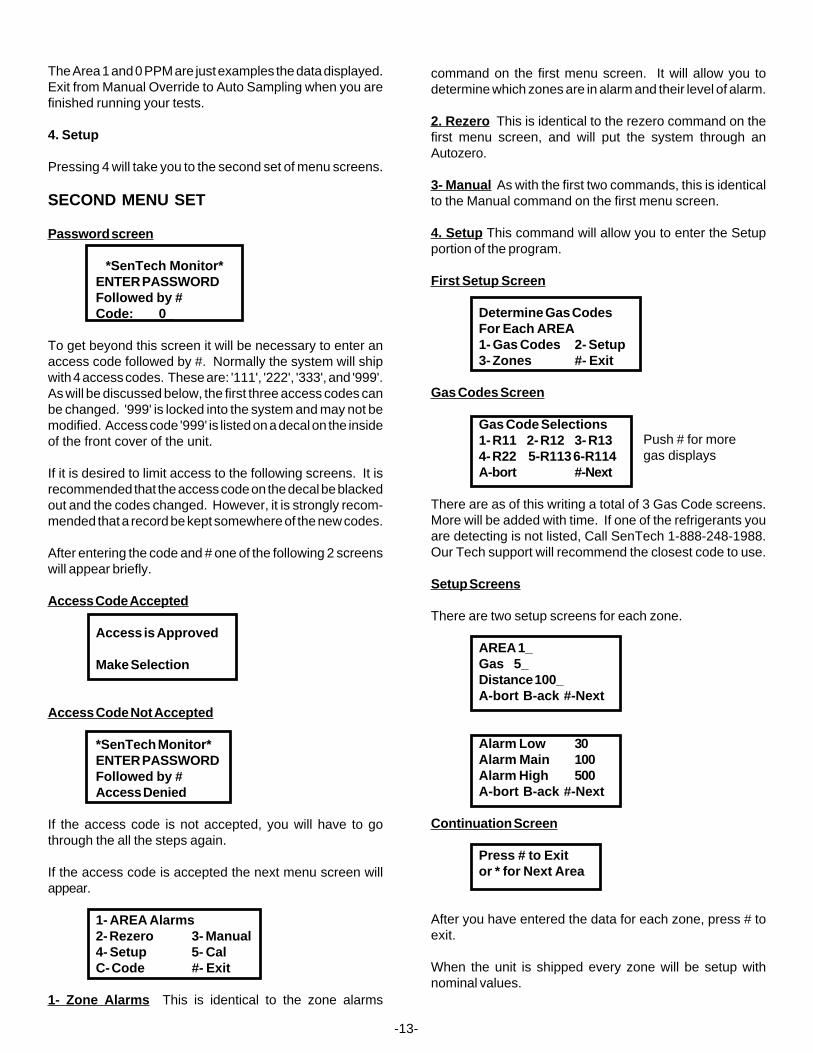
Password screen
*SenTech Monitor*ENTER PASSWORDFollowed by #Code: 0_
To get beyond this screen it will be necessary to enter anaccess code followed by #. Normally the system will shipwith 4 access codes. These are: '111', '222', '333', and '999'.As will be discussed below, the first three access codes canbe changed. '999' is locked into the system and may not bemodified. Access code '999' is listed on a decal on the insideof the front cover of the unit.
If it is desired to limit access to the following screens. It isrecommended that the access code on the decal be blackedout and the codes changed. However, it is strongly recom-mended that a record be kept somewhere of the new codes.
After entering the code and # one of the following 2 screenswill appear briefly.
Access Code Accepted
Access is Approved
Make Selection
Access Code Not Accepted
*SenTech Monitor*ENTER PASSWORDFollowed by #Access Denied
If the access code is not accepted, you will have to gothrough the all the steps again.
If the access code is accepted the next menu screen willappear.
1- AREA Alarms2- Rezero 3- Manual4- Setup 5- CalC- Code #- Exit
1- Zone Alarms This is identical to the zone alarms
-13-
command on the first menu screen. It will allow you todetermine which zones are in alarm and their level of alarm.
2. Rezero This is identical to the rezero command on thefirst menu screen, and will put the system through anAutozero.
3- Manual As with the first two commands, this is identicalto the Manual command on the first menu screen.
4. Setup This command will allow you to enter the Setupportion of the program.
First Setup Screen
Determine Gas CodesFor Each AREA1- Gas Codes 2- Setup3- Zones #- Exit
Gas Codes Screen
Gas Code Selections1- R11 2- R12 3- R134- R22 5-R113 6-R114A-bort #-Next
There are as of this writing a total of 3 Gas Code screens.More will be added with time. If one of the refrigerants youare detecting is not listed, Call SenTech 1-888-248-1988.Our Tech support will recommend the closest code to use.
Setup Screens
There are two setup screens for each zone.
AREA 1_Gas 5_Distance 100_A-bort B-ack #-Next
Alarm Low 30Alarm Main 100Alarm High 500A-bort B-ack #-Next
Continuation Screen
Press # to Exitor * for Next Area
After you have entered the data for each zone, press # toexit.
When the unit is shipped every zone will be setup withnominal values.
Push # for moregas displays
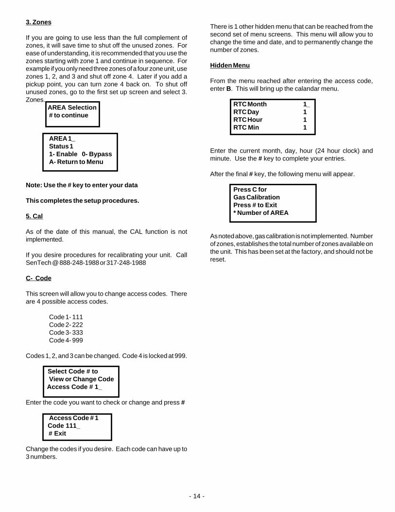
3. Zones
If you are going to use less than the full complement ofzones, it will save time to shut off the unused zones. Forease of understanding, it is recommended that you use thezones starting with zone 1 and continue in sequence. Forexample if you only need three zones of a four zone unit, usezones 1, 2, and 3 and shut off zone 4. Later if you add apickup point, you can turn zone 4 back on. To shut offunused zones, go to the first set up screen and select 3.Zones. AREA Selection
# to continue
AREA 1_Status 11- Enable 0- BypassA- Return to Menu
Note: Use the # key to enter your data
This completes the setup procedures.
5. Cal
As of the date of this manual, the CAL function is notimplemented.
If you desire procedures for recalibrating your unit. CallSenTech @ 888-248-1988 or 317-248-1988
C- Code
This screen will allow you to change access codes. Thereare 4 possible access codes.
Code 1- 111Code 2- 222Code 3- 333Code 4- 999
Codes 1, 2, and 3 can be changed. Code 4 is locked at 999.
Select Code # toView or Change Code
Access Code # 1_
Enter the code you want to check or change and press #
Access Code # 1 Code 111_ # Exit
Change the codes if you desire. Each code can have up to3 numbers.
- 14 -
There is 1 other hidden menu that can be reached from thesecond set of menu screens. This menu will allow you tochange the time and date, and to permanently change thenumber of zones.
Hidden Menu
From the menu reached after entering the access code,enter B. This will bring up the calandar menu.
RTC Month 1_RTC Day 1RTC Hour 1RTC Min 1
Enter the current month, day, hour (24 hour clock) andminute. Use the # key to complete your entries.
After the final # key, the following menu will appear.
Press C forGas CalibrationPress # to Exit* Number of AREA
As noted above, gas calibration is not implemented. Numberof zones, establishes the total number of zones available onthe unit. This has been set at the factory, and should not bereset.
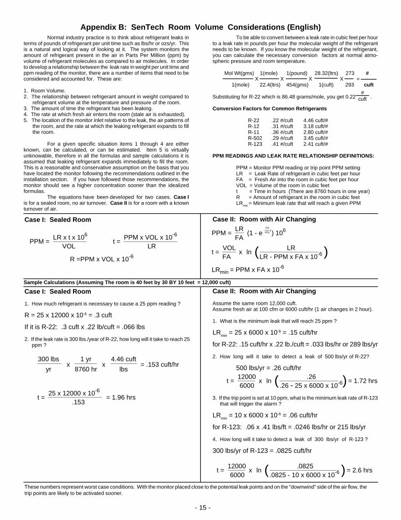
.0825.0825 - 10 x 6000 x 10-6
12000 6000
t = x ln ( ) = 2.6 hrs
.26.26 - 25 x 6000 x 10-6
12000 6000
t = x ln ( ) = 1.72 hrs
x300 lbs 1 yr 4.46 cuft
x = .153 cuft/hryr 8760 hr lbs
25 x 12000 x 10-6 .153
t = = 1.96 hrs
Case II: Room with Air Changing
Case II: Room with Air Changing
Assume the same room 12,000 cuft.Assume fresh air at 100 cfm or 6000 cuft/hr (1 air changes in 2 hour).
1. What is the minimum leak that will reach 25 ppm ?
LRmin
= 25 x 6000 x 10-6 = .15 cuft/hr
for R-22: .15 cuft/hr x .22 lb./cuft = .033 lbs/hr or 289 lbs/yr
2. How long will it take to detect a leak of 500 lbs/yr of R-22?
500 lbs/yr = .26 cuft/hr
3. If the trip point is set at 10 ppm, what is the minimum leak rate of R-123 that will trigger the alarm ?
LRmin
= 10 x 6000 x 10-6 = .06 cuft/hr
for R-123: .06 x .41 lbs/ft = .0246 lbs/hr or 215 lbs/yr
4. How long will it take to detect a leak of 300 lbs/yr of R-123 ?
300 lbs/yr of R-123 = .0825 cuft/hr
LRLR - PPM x FA x 10-6
VOL FA
t =
LR FA
PPM = (1 - e ) 106-FA
VOLt
x ln ( )LRmin = PPM x FA x 10-6
To be able to convert between a leak rate in cubic feet per hourto a leak rate in pounds per hour the molecular weight of the refrigerantneeds to be known. If you know the molecular weight of the refrigerant,you can calculate the necessary conversion factors at normal atmo-spheric pressure and room temperature.
Mol Wt(gms) 1(mole) 1(pound) 28.32(ltrs) 273 # X X X X = 1(mole) 22.4(ltrs) 454(gms) 1(cuft) 293 cuft
Substituting for R-22 which is 86.48 grams/mole, you get 0.22 .
Conversion Factors for Common Refrigerants
R-22 .22 #/cuft 4.46 cuft/#R-12 .31 #/cuft 3.18 cuft/#R-11 .36 #/cuft 2.80 cuft/#R-502 .29 #/cuft 3.45 cuft/#R-123 .41 #/cuft 2.41 cuft/#
PPM READINGS AND LEAK RATE RELATIONSHIP DEFINITIONS:
PPM = Monitor PPM reading or trip point PPM settingLR = Leak Rate of refrigerant in cubic feet per hourFA = Fresh Air into the room in cubic feet per hourVOL = Volume of the room in cubic feett = Time in hours (There are 8760 hours in one year)R = Amount of refrigerant in the room in cubic feetLRmin = Minimum leak rate that will reach a given PPM
Case I: Sealed Room
Case I: Sealed Room
1. How much refrigerant is necessary to cause a 25 ppm reading ?
R = 25 x 12000 x 10-6 = .3 cuft
If it is R-22: .3 cuft x .22 lb/cuft = .066 lbs
2. If the leak rate is 300 lbs./year of R-22, how long will it take to reach 25 ppm ?
These numbers represent worst case conditions. With the monitor placed close to the potential leak points and on the "downwind" side of the air flow, thetrip points are likely to be activated sooner.
Sample Calculations (Assuming The room is 40 feet by 30 BY 10 feet = 12,000 cuft)
- 15 -
#cuft
Appendix B: SenTech Room Volume Considerations (English)Normal industry practice is to think about refrigerant leaks in
terms of pounds of refrigerant per unit time such as lbs/hr or ozs/yr. Thisis a natural and logical way of looking at it. The system monitors theamount of refrigerant present in the air in Parts Per Million (ppm) byvolume of refrigerant molecules as compared to air molecules. In orderto develop a relationship between the leak rate in weight per unit time andppm reading of the monitor, there are a number of items that need to beconsidered and accounted for. These are:
1. Room Volume.2. The relationship between refrigerant amount in weight compared to
refrigerant volume at the temperature and pressure of the room.3. The amount of time the refrigerant has been leaking.4. The rate at which fresh air enters the room (stale air is exhausted).5. The location of the monitor inlet relative to the leak, the air patterns of
the room, and the rate at which the leaking refrigerant expands to fillthe room.
For a given specific situation items 1 through 4 are eitherknown, can be calculated, or can be estimated. Item 5 is virtuallyunknowable, therefore in all the formulas and sample calculations it isassumed that leaking refrigerant expands immediately to fill the room.This is a reasonable and conservative assumption on the basis that youhave located the monitor following the recommendations outlined in theinstallation section. If you have followed those recommendations, themonitor should see a higher concentration sooner than the idealizedformulas.
The equations have been developed for two cases. Case Iis for a sealed room, no air turnover. Case II is for a room with a knownturnover of air.
LR x t x 106 VOL
PPM = PPM x VOL x 10-6
LRt =
R =PPM x VOL x 10-6
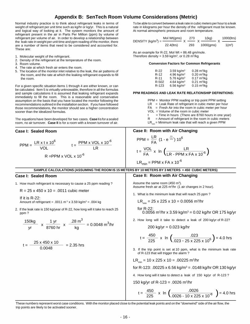
.0026.0026 - 10 x 225 x 10-6
450 225
t = x ln ( ) = 4.0 hrs
.023.023 - 25 x 225 x 106
450225
t = x ln ( ) = 4.0 hrs
x150kg 1 yr .28 m3
x = 0.0048 m3/hryr 8760 hr kg
25 x 450 x 100.0048
t = = 2.35 hrs
LRLR - PPM x FA x 10-6
VOL FA
t =
LR FA
PPM = (1 - e ) 106-FA
VOLt
x ln ( )LRmin = PPM x FA x 10-6
LR x t x 106 VOL
PPM = PPM x VOL x 10-6
LRt =
R =PPM x VOL x 10-6
DENSITY (kg/m3) = X X X
- 16 -
Case II: Room with Air Changing
Case II: Room with Air Changing
Assume the same room (450 m3).Assume fresh air at 225 m3/hr (1 air changes in 2 hour).
1. What is the minimum leak that will reach 25 ppm ?
LRmin
= 25 x 225 x 10 = 0.0056 m3/hr
for R-22: 0.0056 m3/hr x 3.59 kg/m3 = 0.02 kg/hr OR 175 kg/yr
2. How long will it take to detect a leak of 200 kg/yr of R-22?
200 kg/yr = 0.023 kg/hr
3. If the trip point is set at 10 ppm, what is the minimum leak rate of R-123 that will trigger the alarm ?
LRmin
= 10 x 225 x 10 = .00225 m3/hr
for R-123: .00225 x 6.56 kg/m3 = .0148 kg/hr OR 130 kg/yr
4. How long will it take to detect a leak of 150 kg/yr of R-123 ?
150 kg/yr of R-123 = .0026 m3/hr
To be able to convert between a leak rate in cubic meters per hour to a leakrate in kilograms per hour the density of the refrigerant must be known.At normal atmospheric pressure and room temperature.
Mol Wt(gms) 273 1(kg) 1000(ltrs)
22.4(ltrs) 293 1000(gms) 1(m3)
As an example for R-22, Mol Wt = 86.48 gm/mole.Therefore density = 3.59 kg/m3, or 0.28 m3/kg
Conversion Factors for Common Refrigerants
R-22 3.59 kg/m3 0.28 m3/kgR-12 4.96 kg/m3 0.20 m3/kgR-11 5.76 kg/m3 0.17 m3/kgR-502 4.64 kg/m3 0.21 m3/kgR-123 6.56 kg/m3 0.15 m3/kg
PPM READINGS AND LEAK RATE RELATIONSHIP DEFINITIONS:
PPM = Monitor PPM reading or trip point PPM settingLR = Leak Rate of refrigerant in cubic meter per hourFA = Fresh Air into the room in cubic meter per hourVOL = Volume of the room in cubic metert = Time in hours (There are 8760 hours in one year)R = Amount of refrigerant in the room in cubic metersLRmin = Minimum leak rate that will reach a given PPM
Appendix B: SenTech Room Volume Considerations (Metric)
These numbers represent worst case conditions. With the monitor placed close to the potential leak points and on the "downwind" side of the air flow, thetrip points are likely to be activated sooner.
Normal industry practice is to think about refrigerant leaks in terms ofweight of refrigerant per unit time such as kg/hr or kg/yr. This is a naturaland logical way of looking at it. The system monitors the amount ofrefrigerant present in the air in Parts Per Million (ppm) by volume ofrefrigerant per volume of air. In order to develop a relationship betweenthe leak rate in weight per unit time and ppm reading of the monitor, thereare a number of items that need to be considered and accounted for.These are:
1. Molecular weight of the refrigerant.2. Density of the refrigerant at the temperature of the room.3. Room volume.4. The rate at which fresh air enters the room.5. The location of the monitor inlet relative to the leak, the air patterns of
the room, and the rate at which the leaking refrigerant expands to fillthe room.
For a given specific situation items 1 through 4 are either known, or canbe calculated. Item 5 is virtually unknowable, therefore in all the formulasand sample calculations it is assumed that leaking refrigerant expandsimmediately to fill the room. This is a reasonable and conservativeassumption on the basis that you have located the monitor following therecommendations outlined in the installation section. If you have followedthose recommendations, the monitor should see a higher concentrationsooner than the idealized formulas.
The equations have been developed for two cases. Case I is for a sealedroom, no air turnover. Case II is for a room with a known turnover of air.
SAMPLE CALCULATIONS (ASSUMING THE ROOM IS 15 METERS BY 10 METERS BY 3 METERS = 450 CUBIC METERS)
Case I: Sealed Room
Case I: Sealed Room
1. How much refrigerant is necessary to cause a 25 ppm reading ?
R = 25 x 450 x 10 = .0011 cubic meter
If it is R-22: Amount of refrigerant = .0011 m 3 x 3.59 kg/m3 = .004 kg
2. If the leak rate is 150 kg/year of R-22, how long will it take to reach 25 ppm ?

MO
DE
LS
SN
IF-1
A, 4
A, 8
A
12. D
iaph
ragm
pum
p...
..41
0024
13.
5 m
icro
n el
emen
t...
.410
162
14.
Filt
er A
ssem
bly
......
.420
043
17. I
R B
ench
......
......
.....
4200
30
1. L
PB
Boa
rd...
......
......
..42
0034
2. K
eypa
d D
ispl
ay...
......
4200
353.
MM
B B
oard
......
......
...42
0033
4. R
TU
-17
Boa
rd...
......
..42
0031
5. F
use
3 A
mp
Fas
t....
...41
0034
6. R
elay
24
volt
......
......
.410
087
7.
Pre
ssur
e sw
itch
......
.420
038
8.
Tra
nsfo
rmer
T1
......
..41
0039
9.
Tra
nsfo
rmer
T2
......
..42
0036
10.
Coa
rse
Filt
er...
......
..41
0044
11. M
anifo
ld 1
Zon
e...
....4
2004
0
Man
ifold
4 Z
one
......
4200
41
Man
ifold
8 Z
one
......
4200
42
Not
Illu
stra
ted
Coo
ling
filte
r....
......
......
..41
0018
.010
Orif
ice
......
......
......
.410
136
- 17 -
4 Z
one
Man
ifold
Ill
ustr
ated
1
2
34
56
78
9
1011
1213
1417
Tub
e E
nd F
ilter
A
ssem
bly

- 18 -
12
34
56
7T
B1
AC
GR
ND
AC
HO
T
AC
CO
MM
ON
DIA
PH
RA
GM
P
UM
P
F1 B
K
BR
VG
R
BK
W
(UN
ITS
FO
R J
AP
AN
AR
E 1
00V
/200
V)
12
34
56
7T
B1
AC
GR
ND
AC
HO
T
AC
CO
MM
ON
GR
BK
W
(UN
ITS
FO
R J
AP
AN
AR
E 1
00V
/200
V)
VB
R
GN
D
DO
OR
(R
EA
R V
IEW
)
T2-
P1
T2-
P2
JUM
PE
RS
SE
T F
OR
240
VA
CJU
MP
ER
S S
ET
FO
R 1
20V
AC
W
WIR
ING
DIA
GR
AM
41
23
56
7
Z1V
Z2V
Z3V
Z4V Z8V
Z7V
Z6V
Z5V
8/4/
97
T1
5421
109876
432
875
T2
1
3 764 51 21 765432
FA
V
* * ** ** ** **
* 4
& 8
ZO
NE
* 4
& 8
ZO
NE
** 8
ZO
NE
ON
LY**
8 Z
ON
E O
NLY
W
BL
R
BK
JP22
-7
JP22
-8
NC
JP22
-5
JP22
-4
JP22
-3
JP22
-2
JP22
-1
JP11
-1
JP11
-2
JP11
-3
JP11
-4
JP11
-5
JP11
-6
JP11
-8
JP11
-9
JP11
-13
JP11
-14
JP11
-7
5678
31
901
111
214
5678
31
901
111
214
5678
31
901
111
214
13
24
56
7
JP19-6
JP19-4
JP19-2
JP4-
1JP
4-2
JP4-
3
CO
MM
ON
4-20
MA
0-10
VD
C
US
ER
C
ON
NE
CT
ION
S
US
ER
C
ON
NE
CT
ION
S
PR
ES
SU
RE
PR
ES
SU
RE
SW
ITC
H S
WIT
CH
LOM
AIN
HI
AL
AR
M
RE
LA
YS
JP2-3
JP2-1
JP-2
3
JP2A IR BENCH
JP20
LP
B
KE
YP
AD
MM
B
JP2
JP2A
JP22
JP20
JP19JP
3
JP4
JP6
JP8
JP9
JP10
JP11
BN R OR Y GN
BL V GY W
V V OR
OR Y
GN
GY
24 V
DC
R
R R
BN
OR
YB
LV
GY
BN
OR
Y
BN
OR
BL
Y
R
R
TB
2
TB
3
TB
4
TB
5
CO
NN
EC
TIO
NS
US
ER
M
OD
EL
SN
IF-1
A, 4
A, 8
A*
JP23
BK
W BK
GR
W
LIN
EF
ILT
ER
- 19 -
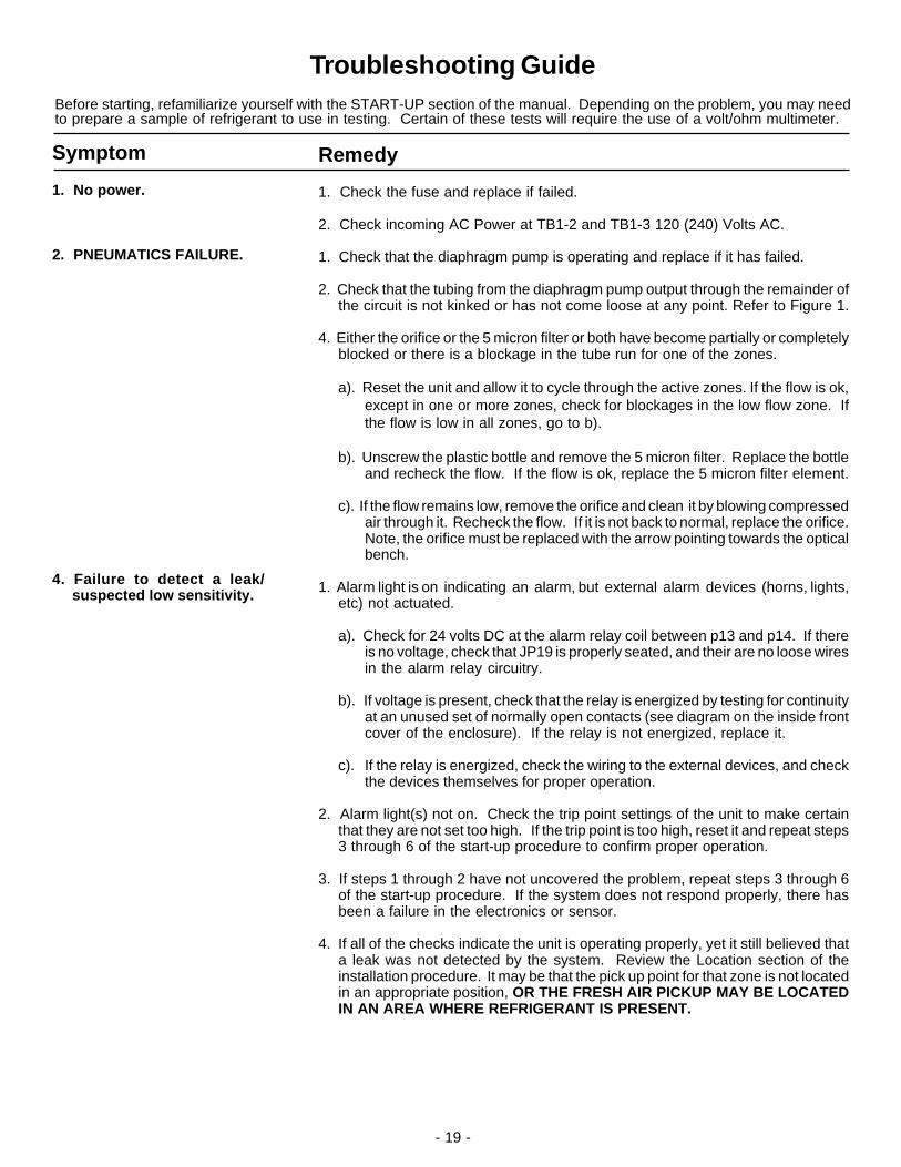
Troubleshooting GuideBefore starting, refamiliarize yourself with the START-UP section of the manual. Depending on the problem, you may needto prepare a sample of refrigerant to use in testing. Certain of these tests will require the use of a volt/ohm multimeter.
Symptom
1. No power.
2. PNEUMATICS FAILURE.
4. Failure to detect a leak/suspected low sensitivity.
Remedy
1. Check the fuse and replace if failed.
2. Check incoming AC Power at TB1-2 and TB1-3 120 (240) Volts AC.
1. Check that the diaphragm pump is operating and replace if it has failed.
2. Check that the tubing from the diaphragm pump output through the remainder ofthe circuit is not kinked or has not come loose at any point. Refer to Figure 1.
4. Either the orifice or the 5 micron filter or both have become partially or completelyblocked or there is a blockage in the tube run for one of the zones.
a). Reset the unit and allow it to cycle through the active zones. If the flow is ok,except in one or more zones, check for blockages in the low flow zone. Ifthe flow is low in all zones, go to b).
b). Unscrew the plastic bottle and remove the 5 micron filter. Replace the bottleand recheck the flow. If the flow is ok, replace the 5 micron filter element.
c). If the flow remains low, remove the orifice and clean it by blowing compressedair through it. Recheck the flow. If it is not back to normal, replace the orifice.Note, the orifice must be replaced with the arrow pointing towards the opticalbench.
1. Alarm light is on indicating an alarm, but external alarm devices (horns, lights,etc) not actuated.
a). Check for 24 volts DC at the alarm relay coil between p13 and p14. If thereis no voltage, check that JP19 is properly seated, and their are no loose wiresin the alarm relay circuitry.
b). If voltage is present, check that the relay is energized by testing for continuityat an unused set of normally open contacts (see diagram on the inside frontcover of the enclosure). If the relay is not energized, replace it.
c). If the relay is energized, check the wiring to the external devices, and checkthe devices themselves for proper operation.
2. Alarm light(s) not on. Check the trip point settings of the unit to make certainthat they are not set too high. If the trip point is too high, reset it and repeat steps3 through 6 of the start-up procedure to confirm proper operation.
3. If steps 1 through 2 have not uncovered the problem, repeat steps 3 through 6of the start-up procedure. If the system does not respond properly, there hasbeen a failure in the electronics or sensor.
4. If all of the checks indicate the unit is operating properly, yet it still believed thata leak was not detected by the system. Review the Location section of theinstallation procedure. It may be that the pick up point for that zone is not locatedin an appropriate position, OR THE FRESH AIR PICKUP MAY BE LOCATEDIN AN AREA WHERE REFRIGERANT IS PRESENT.
- 20 -
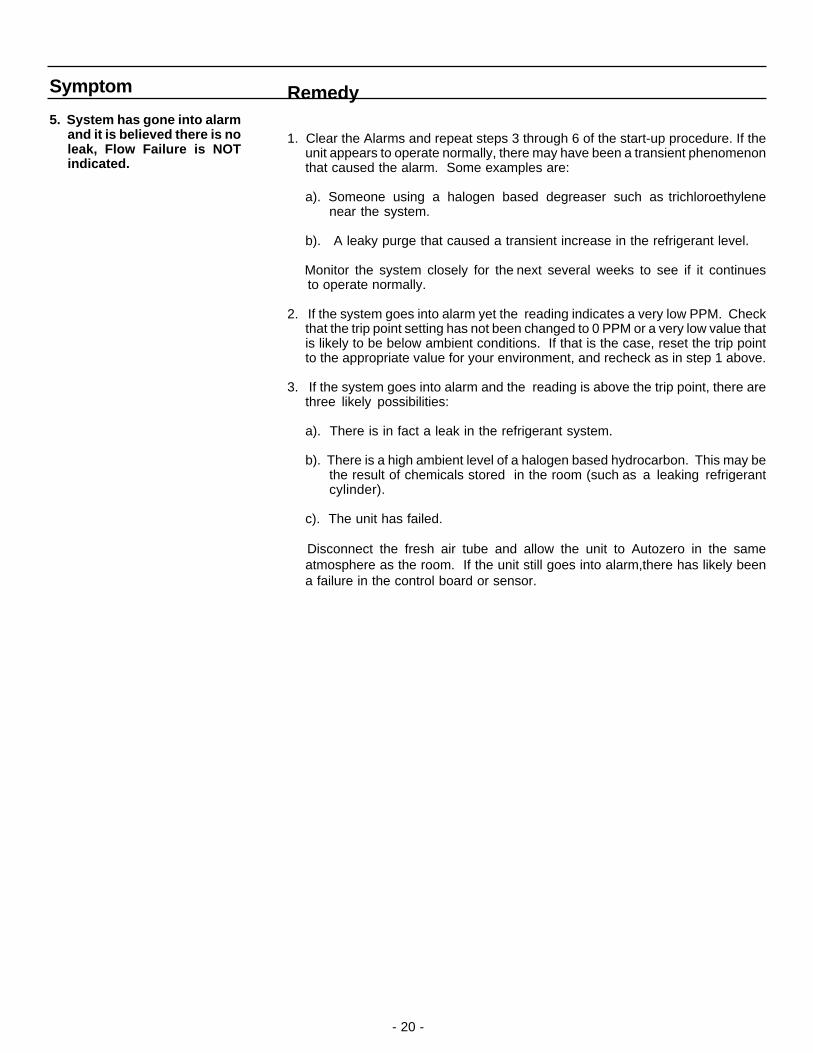
Remedy
1. Clear the Alarms and repeat steps 3 through 6 of the start-up procedure. If theunit appears to operate normally, there may have been a transient phenomenonthat caused the alarm. Some examples are:
a). Someone using a halogen based degreaser such as trichloroethylenenear the system.
b). A leaky purge that caused a transient increase in the refrigerant level.
Monitor the system closely for the next several weeks to see if it continues to operate normally.
2. If the system goes into alarm yet the reading indicates a very low PPM. Checkthat the trip point setting has not been changed to 0 PPM or a very low value thatis likely to be below ambient conditions. If that is the case, reset the trip pointto the appropriate value for your environment, and recheck as in step 1 above.
3. If the system goes into alarm and the reading is above the trip point, there arethree likely possibilities:
a). There is in fact a leak in the refrigerant system.
b). There is a high ambient level of a halogen based hydrocarbon. This may bethe result of chemicals stored in the room (such as a leaking refrigerantcylinder).
c). The unit has failed.
Disconnect the fresh air tube and allow the unit to Autozero in the sameatmosphere as the room. If the unit still goes into alarm,there has likely beena failure in the control board or sensor.
Symptom
5. System has gone into alarmand it is believed there is noleak, Flow Failure is NOTindicated.

- 21 -
www.sentechcorp.comSince 1987
SenTech, gives the following as its complete Limited Warranty Statement:
SenTechManufacturer's Limited Warranty
SenTech warrants to the original purchaser-user that its equipment, as originally supplied, is free fromdefects in materials and workmanship and will perform adequately under normal use and service, subject to thefollowing conditions and limits:
If the equipment or any part or parts thereof prove to be defective in normal use, then such item or partswill be repaired or replaced at the option of SenTech by SenTech, provided that notice of such defect is givenby original purchaser-user to SenTech within one (1) year from the date of original installation (WarrantyRegistration Must Be On File) or 15 months from the date of sale of the equipment to the original purchaserwhichever comes first.
Warranty is made on condition that such original purchaser-user has returned to SenTech the warrantyregistration form applicable to the equipment, duly and fully completed, within (90) days of the date of purchaseby the original purchaser-user.
SenTech's obligation under this warranty is limited exclusively to replacing without charge, or to repairing,at SenTech's option, upon return to Indianapolis, Indiana, transportation charges prepaid, any part or parts thatshall be found to be defective in material or workmanship during the warranty period. Charges for labor (exceptfor labor performed by SenTech factory for repairing defective parts) are not covered and these, plus all othercosts and expenses for transportation, insurance, etc., shall be paid for by the Warrantee. If, upon inspectionby SenTech or its Authorized Service Representative, it is determined that the equipment has not been usedin an appropriate manner as described in the SenTech Operator's Manual or has been subject to misuse,alteration, accident, damage during transit or delivery, or that such part is from a machine on which the serialnumber has been altered or removed, then this warranty is void and of no further force or effect. All decisionsregarding the existence of defects in material or workmanship or other causes shall be made by SenTech'sFactory Representative and shall be final and binding upon the parties. Returns shall only be made upon theprior written authorization thereof by SenTech.
THE FOREGOING LIMITED WARRANTY IS EXPRESSLY MADE IN LIEU OF ANY AND ALL OTHERWARRANTIES, EXPRESS OR IMPLIED, INCLUDING WITHOUT LIMITATION ANY IMPLIED WARRANTYOF MERCHANTABILITY OR FITNESS FOR A PARTICULAR PURPOSE.
The foregoing limited warranty shall not be enlarged or affected by, and no liability or obligation shall arisefrom, SenTech's rendering of technical or other advice, or service, in connection with any of its equipment orparts. Employees, agents, distributors, retailers, and sales representatives are not authorized to makewarranties. Oral or written statements made may them do not constitute warranties and shall not be relied upon.
REPLACEMENT OR REPAIR OF DEFECTIVE EQUIPMENT OR PARTS AS PROVIDED ABOVE IS THEORIGINAL PURCHASER-USER'S SOLE AND EXCLUSIVE REMEDY FOR CONTRACT, WARRANTY,NEGLIGENCE, TORT OR STRICT LIABILITY CLAIMS FOR ANY LOSS, DAMAGE OR EXPENSE ARISINGOR ALLEGED TO ARISE OUT OF THE DESIGN, MANUFACTURE, SALE, DELIVERY OR USE OF SUCHEQUIPMENT AND/OR PARTS. IN NO EVENT SHALL SENTECH BE LIABLE FOR ANY AMOUNT INEXCESS OF THE PURCHASE PRICE OF THE EQUIPMENT, OR FOR LOSS OF USE OR PROFITS, LOSSOF BUSINESS INTERRUPTION, ATTORNEY'S FEES, OR CONSEQUENTIAL, CONTINGENT, INCIDENTALOR SPECIAL DAMAGES CAUSED OR ALLEGED TO CAUSED IN WHOLE OR IN PART BY THENEGLIGENCE, TORT, STRICT LIABILITY, BREACH OF CONTRACT, BREACH OF WARRANTY, OR OTHERBREACH OF DUTY OF OR BY SENTECH.
SenTech Corporation5745 Progress Road
Indianapolis, Indiana 46241
THIS LIMITED WARRANTY IS NOT TRANSFERABLE.

P/N SNAITS10-11-01