INSTALLATION AND OPERATION MANUAL Effective May 1, 2014
36
DESIGNER COLLECTION Drop-in / Undermount / Alcove Whirlpool - Air Bath INSTALLATION AND OPERATION MANUAL Effective May 1, 2014 Installer: this booklet must be given to the product owner. Please note important information below: Distributor Name # Model # Manufacturer’s Date Serial / Registration #
Transcript of INSTALLATION AND OPERATION MANUAL Effective May 1, 2014

D E S I G N E R C O L L E C T I O N D r o p - i n / U n d e r m o u n t / A l c o v e
W h i r l p o o l - A i r B a t h
I N S TA L L AT I O N A N D O P E R AT I O N M A N U A L
E f f e c t i v e M a y 1 , 2 0 1 4
Installer: this booklet must be given to the product owner. Please note important information below:
Distributor Name #
Model #
Manufacturer’s Date
Serial / Registration #

I M P O R TA N T S A F E T Y I N S T R U C T I O N S
WARNING: WHEN USING ELECTRICAL PRODUCTS, BASIC PRECAUTIONS SHOULD BE FOLLOWED, INCLUDING THE FOLLOWING
This manual contains information and instructions for proper operation and maintenance of your MTI bathtub. Failure to follow these instructions could result in personal injury, electrical shock or fire.
INSTRUCTIONS PERTAINING TO RISK OF FIRE, ELECTRIC SHOCK, OR INJURY TO PERSONS.
READ AND FOLLOW ALL INSTRUCTIONS Do not permit children to use this unit unless they are closely supervised by an adult at all
times. Supervision is also required when bath is used by an elderly or handicapped individual.
Never leave a full or filling bath unattended.
Use this unit only for its intended use as described in this manual. Do not use attachments not recommended by the manufacturer. Never drop or insert any object into any opening.
O W N E R ’ S M A N U A LA N D I N S T A L L A T I O N G U I D E
Thank you for choosing an MTI bath. You have purchased the best-built acrylic bath in America. We know it will give you many years of pleasure. The instructions in this booklet will provide you with the information you need to install and operate this unit. This information is also available on mtibaths.com. Our customer service department is available to answer any additional questions you may have pertaining to the installation and operation of your bath. Call 800-783-8827 to speak to our Service Department. For faster service, please have your warranty registration number (serial number) ready when calling. The registration number can be found on the CSA/UL label adhered to the exterior surface of the tub. This sticker is typically placed several inches above the pump or blower.
S A M P L E
▲!
▲!
IMPORTANT: Locate and note your serial number on the cover of this manual for any future service needs.
▲!
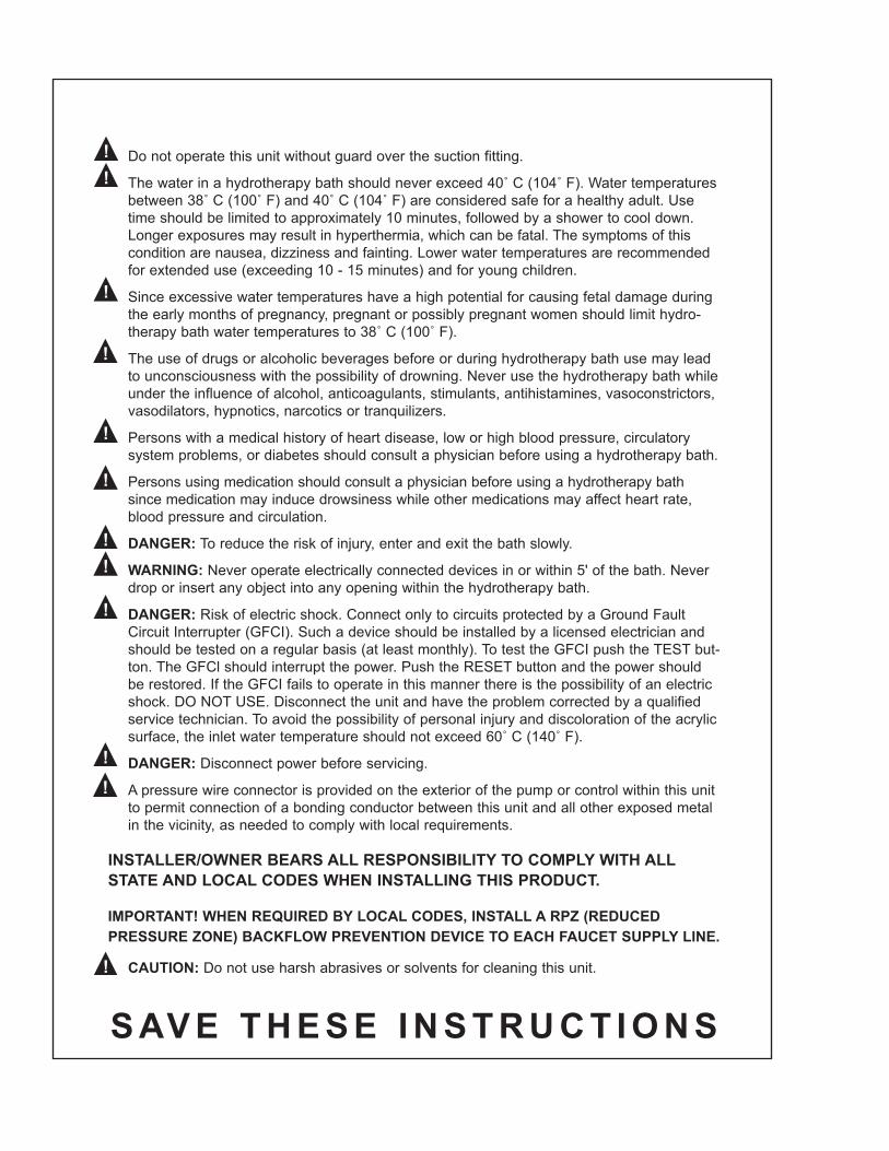
Do not operate this unit without guard over the suction fitting.
The water in a hydrotherapy bath should never exceed 40˚ C (104˚ F). Water temperatures between 38˚ C (100˚ F) and 40˚ C (104˚ F) are considered safe for a healthy adult. Use time should be limited to approximately 10 minutes, followed by a shower to cool down. Longer exposures may result in hyperthermia, which can be fatal. The symptoms of this condition are nausea, dizziness and fainting. Lower water temperatures are recommended for extended use (exceeding 10 - 15 minutes) and for young children.
Since excessive water temperatures have a high potential for causing fetal damage during the early months of pregnancy, pregnant or possibly pregnant women should limit hydro-therapy bath water temperatures to 38˚ C (100˚ F).
The use of drugs or alcoholic beverages before or during hydrotherapy bath use may lead to unconsciousness with the possibility of drowning. Never use the hydrotherapy bath while under the influence of alcohol, anticoagulants, stimulants, antihistamines, vasoconstrictors, vasodilators, hypnotics, narcotics or tranquilizers.
Persons with a medical history of heart disease, low or high blood pressure, circulatory system problems, or diabetes should consult a physician before using a hydrotherapy bath.
Persons using medication should consult a physician before using a hydrotherapy bath since medication may induce drowsiness while other medications may affect heart rate, blood pressure and circulation.
DANGER: To reduce the risk of injury, enter and exit the bath slowly.
WARNING: Never operate electrically connected devices in or within 5' of the bath. Never drop or insert any object into any opening within the hydrotherapy bath.
DANGER: Risk of electric shock. Connect only to circuits protected by a Ground Fault Circuit Interrupter (GFCI). Such a device should be installed by a licensed electrician and should be tested on a regular basis (at least monthly). To test the GFCI push the TEST but-ton. The GFCl should interrupt the power. Push the RESET button and the power should be restored. If the GFCI fails to operate in this manner there is the possibility of an electric shock. DO NOT USE. Disconnect the unit and have the problem corrected by a qualified service technician. To avoid the possibility of personal injury and discoloration of the acrylic surface, the inlet water temperature should not exceed 60˚ C (140˚ F).
DANGER: Disconnect power before servicing.
A pressure wire connector is provided on the exterior of the pump or control within this unit to permit connection of a bonding conductor between this unit and all other exposed metal in the vicinity, as needed to comply with local requirements.
INSTALLER/OWNER BEARS ALL RESPONSIBILITY TO COMPLY WITH ALL STATE AND LOCAL CODES WHEN INSTALLING THIS PRODUCT.
IMPORTANT! WHEN REQUIRED BY LOCAL CODES, INSTALL A RPZ (REDUCED PRESSURE ZONE) BACKFLOW PREVENTION DEVICE TO EACH FAUCET SUPPLY LINE.
CAUTION: Do not use harsh abrasives or solvents for cleaning this unit.
S AV E T H E S E I N S T R U C T I O N S
▲!▲!
▲!
▲!
▲!▲!
▲!▲!▲!
▲!▲!
▲!
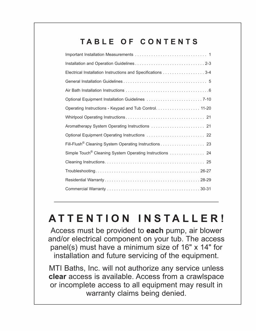
T A B L E O F C O N T E N T SImportant Installation Measurements . . . . . . . . . . . . . . . . . . . . . . . . . . . . . . . 1
Installation and Operation Guidelines . . . . . . . . . . . . . . . . . . . . . . . . . . . . . . 2-3
Electrical Installation Instructions and Specifications . . . . . . . . . . . . . . . . . . 3-4
General Installation Guidelines . . . . . . . . . . . . . . . . . . . . . . . . . . . . . . . . . . . . 5
Air Bath Installation Instructions . . . . . . . . . . . . . . . . . . . . . . . . . . . . . . . . . . . .6
Optional Equipment Installation Guidelines . . . . . . . . . . . . . . . . . . . . . . . . 7-10
Operating Instructions - Keypad and Tub Control . . . . . . . . . . . . . . . . . . . 11-20
Whirlpool Operating Instructions . . . . . . . . . . . . . . . . . . . . . . . . . . . . . . . . . . 21
Aromatherapy System Operating Instructions . . . . . . . . . . . . . . . . . . . . . . . 21
Optional Equipment Operating Instructions . . . . . . . . . . . . . . . . . . . . . . . . . 22
Fill-Flush® Cleaning System Operating Instructions . . . . . . . . . . . . . . . . . . . 23
Simple Touch® Cleaning System Operating Instructions . . . . . . . . . . . . . . . 24
Cleaning Instructions . . . . . . . . . . . . . . . . . . . . . . . . . . . . . . . . . . . . . . . . . . . 25
Troubleshooting . . . . . . . . . . . . . . . . . . . . . . . . . . . . . . . . . . . . . . . . . . . . . 26-27
Residential Warranty . . . . . . . . . . . . . . . . . . . . . . . . . . . . . . . . . . . . . . . . . 28-29
Commercial Warranty . . . . . . . . . . . . . . . . . . . . . . . . . . . . . . . . . . . . . . . . 30-31
A T T E N T I O N I N S T A L L E R !Access must be provided to each pump, air blower
and/or electrical component on your tub. The access panel(s) must have a minimum size of 16" x 14" for installation and future servicing of the equipment.
MTI Baths, Inc. will not authorize any service unless clear access is available. Access from a crawlspace or incomplete access to all equipment may result in
warranty claims being denied.

1
A: Overall length
B: Overall width
C: Overall height
D: Height – bottom of flange/rim to exterior tub bottom
E: Inside tub height
F: Center of overflow to bottom interior floor of tub
G: Drain center to right tub edge
H: Inside bowl width at top of bowl
I: Inside bowl width at bottom of bowl
J: Inside bowl length at top of bowl
K: Inside bowl length at bottom of bowl
L: Allow 1/2" to 1" to D for wet bedding
M: Pre-leveled frame height* – Adds 1/2"- 3" to height
N: Air bath height* – Adds approximately 2" to height
P: Flange edge depth
Q: Top flange width
R: Drain center to edge of flange
* Please measure actual tub prior tobuilding any decking or framing.Specifications are subject to changewithout notice. MTI Baths, Inc. is notresponsible for any labor or materialcharges for preparatory work.
I M P O R T A N T I N S T A L L A T I O N M E A S U R E M E N T S
2
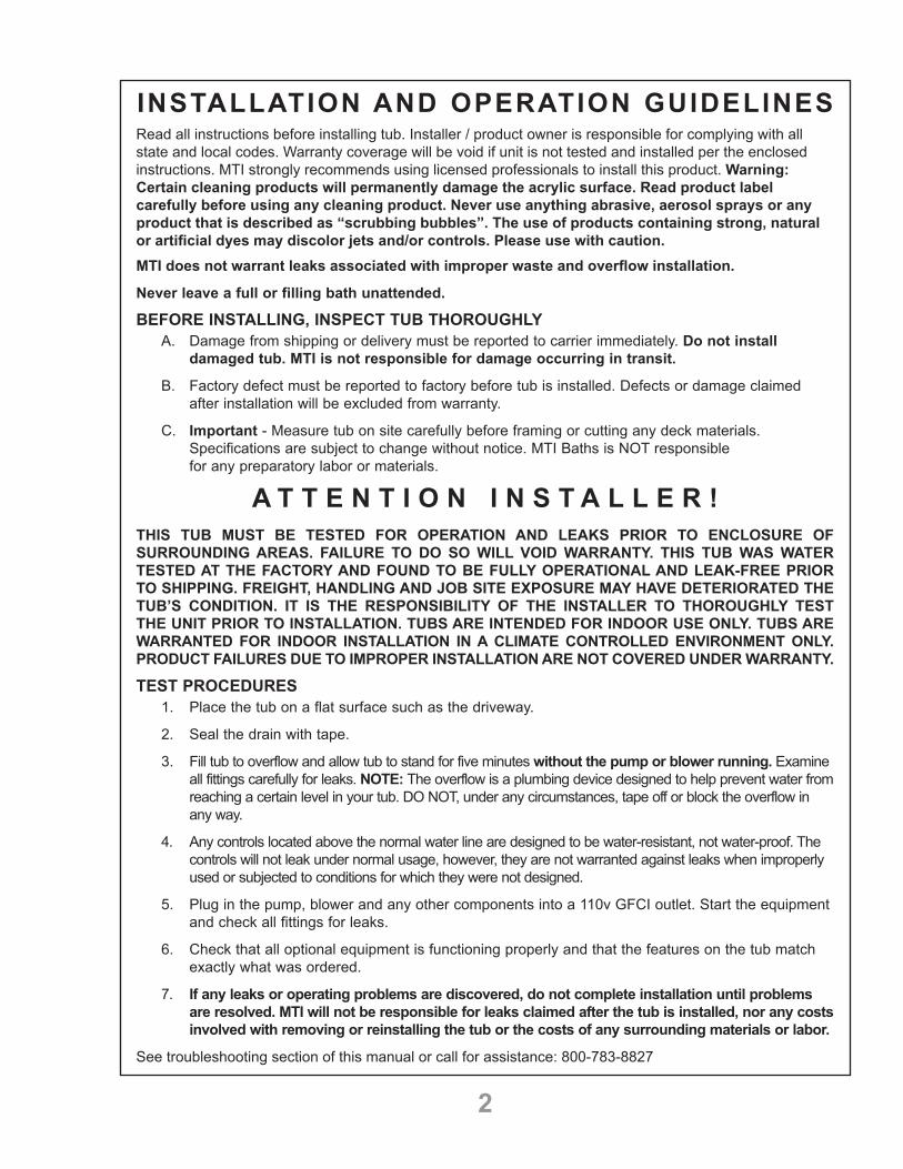
INSTALLATION AND OPERATION GUIDELINESRead all instructions before installing tub. Installer / product owner is responsible for complying with all state and local codes. Warranty coverage will be void if unit is not tested and installed per the enclosed instructions. MTI strongly recommends using licensed professionals to install this product. Warning: Certain cleaning products will permanently damage the acrylic surface. Read product label carefully before using any cleaning product. Never use anything abrasive, aerosol sprays or any product that is described as “scrubbing bubbles”. The use of products containing strong, natural or artificial dyes may discolor jets and/or controls. Please use with caution.MTI does not warrant leaks associated with improper waste and overflow installation.
Never leave a full or filling bath unattended.
BEFORE INSTALLING, INSPECT TUB THOROUGHLYA. Damage from shipping or delivery must be reported to carrier immediately. Do not install
damaged tub. MTI is not responsible for damage occurring in transit.
B. Factory defect must be reported to factory before tub is installed. Defects or damage claimed after installation will be excluded from warranty.
C. Important - Measure tub on site carefully before framing or cutting any deck materials.Specifications are subject to change without notice. MTI Baths is NOT responsible for any preparatory labor or materials.
A T T E N T I O N I N S T A L L E R !THIS TUB MUST BE TESTED FOR OPERATION AND LEAKS PRIOR TO ENCLOSURE OF SURROUNDING AREAS. FAILURE TO DO SO WILL VOID WARRANTY. THIS TUB WAS WATER TESTED AT THE FACTORY AND FOUND TO BE FULLY OPERATIONAL AND LEAK-FREE PRIOR TO SHIPPING. FREIGHT, HANDLING AND JOB SITE EXPOSURE MAY HAVE DETERIORATED THE TUB’S CONDITION. IT IS THE RESPONSIBILITY OF THE INSTALLER TO THOROUGHLY TEST THE UNIT PRIOR TO INSTALLATION. TUBS ARE INTENDED FOR INDOOR USE ONLY. TUBS ARE WARRANTED FOR INDOOR INSTALLATION IN A CLIMATE CONTROLLED ENVIRONMENT ONLY. PRODUCT FAILURES DUE TO IMPROPER INSTALLATION ARE NOT COVERED UNDER WARRANTY.
TEST PROCEDURES1. Place the tub on a flat surface such as the driveway.
2. Seal the drain with tape.
3. Fill tub to overflow and allow tub to stand for five minutes without the pump or blower running. Examineall fittings carefully for leaks. NOTE: The overflow is a plumbing device designed to help prevent water fromreaching a certain level in your tub. DO NOT, under any circumstances, tape off or block the overflow inany way.
4. Any controls located above the normal water line are designed to be water-resistant, not water-proof. Thecontrols will not leak under normal usage, however, they are not warranted against leaks when improperlyused or subjected to conditions for which they were not designed.
5. Plug in the pump, blower and any other components into a 110v GFCI outlet. Start the equipmentand check all fittings for leaks.
6. Check that all optional equipment is functioning properly and that the features on the tub matchexactly what was ordered.
7. If any leaks or operating problems are discovered, do not complete installation until problemsare resolved. MTI will not be responsible for leaks claimed after the tub is installed, nor any costsinvolved with removing or reinstalling the tub or the costs of any surrounding materials or labor.
See troubleshooting section of this manual or call for assistance: 800-783-8827

3
110VACPowerSupply
See Manufacturers Wiring Diagram on Motor
Grounding Conductor(Pressure Wire Connector)
GFCI
MotorGreen/Ground
White/Neutral
Black/Hot
Always protect tub from construction damage by using a protective cover. Damage, including chips and scratches, incurred at the jobsite is excluded from warranty, but may be repaired by qualified technician at the owner’s expense. Do not stand in the tub or store materials in the tub during construction. Do not store tub in temperatures below 32 degrees Fahrenheit. Proper waste and overflow installation is the responsibility of the installer. MTI does not warrant leaks associated with improper waste and overflow installation.
There are many possible ways to install your new MTI tub, and some may require different framing than the following instructions. Keep in mind that the framing should always provide a level surface for the rim of the tub and sufficient space below the tub for bedding compound. Access must be provided to each pump, air blower and / or electrical component on your tub. The access panels must have a minimum size of 16" x 14" for installation and future servicing of the equipment. MTI will not authorize any service unless clear access is available. The installer is responsible for providing access for any future servicing. The bolts/screws through the mounting feet on the pump or blower may be loosened or removed once the tub is in place if necessary for future servicing. Each MTI tub may be ordered with a wide array of options. If your tub has more than two power cords, the power cords will be gathered together with a bright yellow hang tag to indicate the number of power cords to be plugged in for proper operation. See electrical specifications on page 4.
Additional access to plumbing fixtures is strongly recommended. It is the responsibility of the installer to comply with local plumbing codes regarding pump and plumbing access. Note: Do not allow any material such as insulation within 8" of pump. Pump and blower must have sufficient air space surrounding them for circulation.
ELECTRICAL INSTALLATION INSTRUCTIONS Warning - When installing or using electrical products, basic precautions should always be followed, including:
1. All MTI whirlpools, air baths and soaking tubs equipped with an inline heater require dedicated110V circuits for the electrical components. Please see Electrical Specifications on page 4. Manyoptions may be combined on a 20 amp circuit, as long as total amps of combined options areconsidered. If your tub has more than two power cords, the power cords will be gathered togetherwith a hang tag indicating how many items must be plugged in for proper operation. This circuitmust be connected to a supply that is protected by a ground fault circuit interrupter (GFCI).Such a GFCI should be provided by the installer and tested on a routine basis. To test the GFCI,push the test button. The GFCI should interrupt power. Push the reset button. Power should berestored. If the GFCI fails to operate in this manner, there is a ground current flowing, indicatingthe possibility of electric shock. Do not use this unit. Disconnect the unit and have the problemcorrected by a qualified service representative before using.
2. Every MTI whirlpool pump, heater or air blower is supplied with a 29" grounded plug to be pluggedinto a separate GFCI outlet. Under no circumstance should you alter the provided supply cord.Products do not require hardwiring or separate, wall-mounted switch.
3. A pressure wire connector is supplied on the exterior of the pump to permit connection of aNo.8AWG (8.4mm) solid copper bonding conductor* between this unit and all other electricalequipment and exposed metal in the vicinity as needed to comply with local requirements.
*NOTE: Air blowers do not require a bonding conductor. WARNING: Unauthorized modification may cause unsafe operation and poor performance of the
product. Do not relocate the whirlpool pump, or make other modifications to the whirlpool system, as this could adversely affect the performance and safe operation of the whirlpool. MTI shall not be liable under its warranty or otherwise for personal injury or damage caused by any such unauthorized modification.

4
IMPORTANT SAFETY INSTRUCTIONS PERTAINING TO A RISK OF FIRE, ELECTRIC SHOCK, OR INJURY TO PERSONS.
WARNING— When using electrical products, basic precautions should always be followed, including these: (Please read and follow all directions. Save these instructions.)
1. DANGER: To reduce the risk of injury, do not allow children or infirmed persons to use this productunless they are supervised at all times.
2. This MTI hydrotherapy unit is designed for use only as described in this manual. Do not useattachments not recommended by the manufacturer.
3. Do not drop or insert any object into any opening.
4. Do not operate this tub without the guard over the suction fitting (water intake). The guard is asafety device that reduces the potential hazard of hair or body entrapment. Keep hair and bodyaway from suction guard when pump is running.
5. Anyone under doctor’s care, pregnant, or whose health is poor should check with a physician beforeusing any whirlpool bath system.
6. Recommended length of hydrotherapy bath is 10 minutes. However, if you become dizzy ornauseous or develop a headache, get out at once and cool down. Get medical attention if symptomspersist. Also check with your physician before using this system again.
7. Do not use immediately after eating or while under the influence of drugs or alcohol.
8. Before servicing unit, shut off all electrical outlets as more than one outlet may be energized.
Electrical Specifications*Please see tub specification sheet and/or your order receipt for electrical components included. In addition, each component will have electrical specification listed on the product label.
Air Blower 110 VAC 8.8 AMP Pumps: • 1 bhp pump 110 VAC 6.3 AMP
• 1.25 bhp pump 110 VAC 8 AMP• 2 bhp pump 110 VAC 10 AMP• 3 bhp pump 110 VAC 13.5 AMP• Stream Bath pump 110 VAC 3 AMP• Waterfall pump 110 VAC 6.3 AMP• 3.5 bhp 220-volt spa pump 220 VAC 8.5 AMP
1500-Watt Inline Heater for Whirlpools 110 VAC 12.5 AMP650-Watt Inline Heater for Whirlpools 110 VAC 5.3 AMP1500-Watt Pump/Heater combo - for "HTISOAK" option 110 VAC 18 AMPLED Lighting (Set of Two) 110 VAC 1 AMPOzone Bath Sanitation System 110 VAC 1 AMPRadiance® 110 VAC 5 AMPSimple Touch Cleaning System 110 VAC 1 AMPTsubo-Hydromassage Control Box 110 VAC 1 AMPLow-Water Sensor 110 VAC 1 AMP*Subject to change without notice. It is the responsibility of the installer to comply with all State and Local codes.

5
GENERAL INSTALLATION GUIDELINES Specific air bath installation instructions are on page 6.Do not begin building any structure for your tub until your tub arrives. All printed specifications for MTI tubs have +/- ½" tolerance AND ARE SUBJECT TO CHANGE AT ANY TIME. Take all final installation dimensions from your tub. Note: air baths, the pre-leveled foam base and pre-leveled frame add approximately 2-3 inches to the height of the tub. The bolts/screws through the mounting feet on the pump or blower may be loosened or removed once the tub is in place if necessary for future servicing.MTI tubs are not equipped with leveling feet. The tub must be leveled from the top flange in both directions and bedding compound used underneath for proper operation. MTI recommends Quikrete #1103 sand/topping mix. Plaster or sheet rock mud are NOT sufficient bedding compounds. Determine the final height of the tub rim by measuring from the underside of the rim to the floor on the drain side and add ½" to allow for bedding compound. If your tub has a pre-leveled foam base or air system, do not add ½" since wet-bedding is not necessary. The tub must be leveled by the rim, and supported by the bedding (or foam base) under the full length of the tub bottom. MTI recommends using a plastic sheet barrier on top of and underneath the bedding compound. Carefully lower tub into place. Shift tub side to side to settle into compound. The tub will not drain properly if not level, both front to back and side to side. Use care not to damage any plumbing, wiring or other options when bedding the tub. Let compound harden overnight before use. Failure to properly bed the tub will void any warranty on the tub shell.Note: The pre-leveled frame eliminates the need to frame the walls or use bedding compound to level the tub. The pre-leveled frame adds ½ to 3 inches of height, depending on the specific model of tub.
ALCOVE OR THREE WALL INSTALLATIONMark a level line on the stud walls using the measurement determined above. A 2x2 or similar stringer will be attached to the studs touching this line. All mounting surfaces must be level to allow for proper drainage. Framing of the same height should be constructed across the front of the tub for skirt, tile or other material. Remember to allow for access to each pump, blower and/or electrical component.
DROP INUse the above dimension as the finished deck height from the floor. The drop in opening should be approximately 1-½ inches smaller than the outside dimensions of the tub. This will create a ¾ inch ledge to support the entire rim of the tub. It is best to have as large an opening as possible in the deck to clear the plumbing and other tub accessories. Full size templates for oval or odd shaped tubs can be purchased through your distributor. The bottom of the tub must be fully supported with bedding compound and must bear the weight of the tub, water and bather. Under no circumstances should the tub “hang” by the top flange.
UNDERMOUNTMTI does not make recommendations as to the size and shape of the opening for undermount installation. Do NOT use any templates supplied by MTI for undermounting. Construct framing for the tub using the measurement determined above; this structure is to level the tub. Additional framing must be provided around the tub to support the weight of the decking material.The rim of the tub is not to bear the weight of the deck material! Have tub at jobsite and measure or template very carefully before cutting any decking materials. MTI is not responsible for any preparatory labor or materials. If your application calls for solid surface material covering only the width of the tub flange, additional support is not necessary.
INTEGRAL SKIRTED All of MTI’s Integral Skirted tubs come with several standard features including an integral molded front skirt, integral three-sided tile flange and a pre-leveled foam base. These tubs are designed for three-wall alcove installation applications. See above for guidelines.
1. Slide tub into installation location. Check to ensure that the tub is level to allow for proper drainage. If the tub islevel, proceed to step two. If the tub is not level, use bedding compound to level tub.
2. Carefully drill 1/8" holes through the tile flange at each stud location. Secure to stud with screws, beingcareful not to over-tighten as this may cause the acrylic to crack or chip. Do not attempt to drive nailsthrough the integral flange. See illustrations on page 7.
Leveling Stringers
For whirlpools and air systems, be sure to provide an opening of at least 16" x 14" for pump access. MTI's optional skirts will often provide this access.
For whirlpools and air systems, be sure toprovide an opening of atleast 16" x 14" for pumpaccess. MTI's optionalskirts will often providethis access.
6
AIR BATH INSTALLATION INSTRUCTIONSDo not attempt to remove the foam or board from the bottom of the tub. Doing so may cause damage and will void the warranty. Do not remove the wires attached to the sensors located on each side of the drain.
1. Never handle the bath by the blower, piping or other equipment.2. Make sure the manifold and airlines are protected when moving the tub into the house.3. An access panel of at least 16" x 14" must be provided for the blower for any future servicing.4. The blower must not be insulated and must have sufficient air space to permit proper operation.
Surrounding ambient air temperature should be between 72°F and 86°F.5. The heating element in your blower heats the air blown into the tub to prevent the water from cooling
too quickly. It will not, under any circumstances, reheat or maintain the temperature of the bath water.6. The area underneath and around the tub must be cleaned thoroughly before finalizing installation to
prevent any particles from entering the blower or being blown into the air jets.7. Before filling the tub, clean installation debris and dirt from the interior of the tub. If necessary, use the
soft brush attachment of a vacuum cleaner.8. Fill tub and test for proper operation and leaks. Note: The blower must be plugged into a 110V
GFCI protected outlet.9. The mounting bolts may be loosened or removed to aid in future servicing.
Note: Each MTI air system is equipped with two sensors on the floor of the bath near the drain. Every time water is introduced to the bath and drained, either by showering, bathing or cleaning, the sensors activate the purge/drying cycle. The cycle will start approximately 7 minutes after the bath is drained and run for 1-2 minutes. The purge cycle will activate even when the air bath has not been turned on. To cancel the purge, simply press the on/off button for the air system. This will delay the purge for 7 minutes. Pressing the on/off button to delay the purge a second time will cancel the purge until the next use.
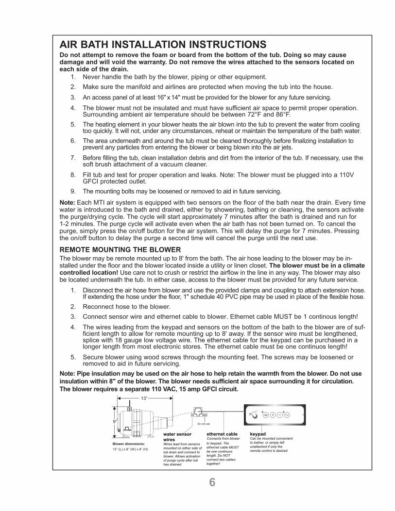
REMOTE MOUNTING THE BLOWERThe blower may be remote mounted up to 8' from the bath. The air hose leading to the blower may be in-stalled under the floor and the blower located inside a utility or linen closet. The blower must be in a climate controlled location! Use care not to crush or restrict the airflow in the line in any way. The blower may also be located underneath the tub. In either case, access to the blower must be provided for any future service.
1. Disconnect the air hose from blower and use the provided clamps and coupling to attach extension hose.If extending the hose under the floor, 1" schedule 40 PVC pipe may be used in place of the flexible hose.
2. Reconnect hose to the blower.3. Connect sensor wire and ethernet cable to blower. Ethernet cable MUST be 1 continous length! 4. The wires leading from the keypad and sensors on the bottom of the bath to the blower are of suf-
ficient length to allow for remote mounting up to 8' away. If the sensor wire must be lengthened, splice with 18 gauge low voltage wire. The ethernet cable for the keypad can be purchased in a longer length from most electronic stores. The ethernet cable must be one continuos length!
5. Secure blower using wood screws through the mounting feet. The screws may be loosened orremoved to aid in future servicing.
Note: Pipe insulation may be used on the air hose to help retain the warmth from the blower. Do not use insulation within 8" of the blower. The blower needs sufficient air space surrounding it for circulation. The blower requires a separate 110 VAC, 15 amp GFCI circuit.
ethernet cableConnects from blower to keypad. The ethernet cable MUST be one continuos length. Do NOT connect two cables together!
water sensor wires Wires lead from sensors mounted on either side of tub drain and connect to blower. Allows activation of purge cycle after tub has drained.
01
keypadCan be mounted convenient to bather, or simply left unattached if only the remote control is desired.
Do not use.
13”
9”
Blower dimensions: 13” (L) x 8” (W) x 9” (H)

7
OPTIONAL EQUIPMENT INSTALLATION GUIDELINESTHE OPTIONS BELOW ARE NOT STANDARD ON EVERY BATH. PLEASE CHECK YOUR ORDER FOR ANY ADDITIONAL OPTIONS ADDED.
INLINE HEATER OPTIONS:HTI - The heater has a separate power cord that must be plugged into a 110 VAC,15 AMP, GFCI protected outlet. There is an indicator light on the heater to check for operation. There is no on/off control for the heater; it turns on each time the pump is activated.
HTISOAK - If your tub came equipped with the separate recirculating pump/heater combination, there will be a separate on/off control on the tub to activate the inline heater. Both the pump and heater must be plugged into a 110 VAC, 20 amp, GFCI protected outlet.
RADIANCE® - Each Radiance® system comes with an on/off touch pad, or designated icon on the key-pad, and transformer box equipped with a 27" power cord. There are two heated zones for each Radiance system purchased. To install, simply plug the transformer box into a 110 V, GFCI protected outlet. The transformer box draws 5 amps.
STREAM BATH - Requires a 110V, 15 Amp GFCI circuit. Simply plug the control box into a GFCI outlet. The pump draws 3 Amps.
TILE FLANGE - FACTORY-INSTALLED1. Determine mounting height of tub. 2. Make sure tub is properly bedded and level from front to back and side to side. 3. Screw through the flange into studs. No pre-drilling is necessary. The tile flange is not designed to support the weight of the tub!
4. Seal / fill the void between the tile flange and tub with clear silicone.
TILE FLANGE KIT – FIELD INSTALLATION1. Clean tub flange.2. Apply supplied adhesive to tub flange and tile flange with brush, being careful not to get adhesive on top of tub.3. Position tub 2-3" from wall.4. Apply tile flange to tub flange.5. Position the tub against the walls. Adhesive will set in five minutes.6. Seal / fill the void between the tile flange and tub with clear silicone.7. Trim any excess flange.
INTEGRAL TILE FLANGEDetermine mounting height of front flange of tub. If installing with optional skirt, mounting height is the height of the skirt. With front flange at proper height, shim tub until level. Care-fully drill 1/8" holes through the tile flange at each stud loca-tion. Use bedding compound to support tub to correct height. Secure to stud with screws, being careful not to over-tighten as this may cause acrylic to crack or chip. Do not attempt to drive nails through the integral flange. See images at right.
PRE-LEVELED FRAMEPlace tub into proper location and attach to floor or studs with 2" screws drilled through frame. This system does not require bedding compound unless subfloor is uneven and unit must be shimmed to achieve level. The pre-leveled frame adds approximately 1/2"-3" to the height of the bath.
STUD
WALL
Tub Flange
Tile and Backer Board
Sealant
2x4 Mounted on EdgeAll Tub Mounts Must Be Level
Tile Flange
8
OPTIONAL EQUIPMENT INSTALLATION GUIDELINES (continued)
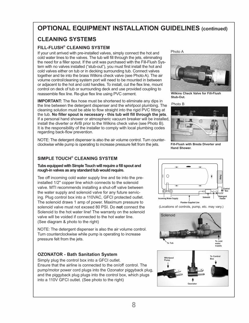
CLEANING SYSTEMSFILL-FLUSH® CLEANING SYSTEMIf your unit arrived with pre-installed valves, simply connect the hot and cold water lines to the valves. The tub will fill through the jets, eliminating the need for a filler spout. If the unit was purchased with the Fill-Flush Sys-tem with no valves installed (“stub-out”), you must first install the hot and cold valves either on tub or in decking surrounding tub. Connect valves together and tie into the brass Wilkins check valve (see Photo A). The air volume control/cleaning system port will need to be mounted in between or adjacent to the hot and cold handles. To install, cut the flex line, mount control on deck of tub or surrounding deck and use provided coupling to reassemble flex line. Re-glue flex line using PVC cement.
IMPORTANT: The flex hose must be shortened to eliminate any dips in the line between the detergent dispenser and the whirlpool plumbing. The cleaning solution must be able to flow straight into the rigid PVC fitting at the tub. No filler spout is necessary - this tub will fill through the jets. If a personal hand shower or atmospheric vacuum breaker will be installed, install the diverter or AVB prior to the Wilkins check valve (see Photo B). It is the responsibility of the installer to comply with local plumbing codes regarding back-flow prevention.
NOTE: The detergent dispenser is also the air volume control. Turn counter-clockwise while pump is operating to increase pressure felt from the jets.
SIMPLE TOUCH® CLEANING SYSTEMTubs equipped with Simple Touch will require a fill spout and rough-in valves as any standard tub would require.
Tee off incoming cold water supply line and tie into the pre-installed 1/2" copper line which connects to the solenoid valve. MTI recommends installing a shut-off valve between the water supply and solenoid valve for any future servic-ing. Plug control box into a 110VAC, GFCI protected outlet. The solenoid draws 1 amp of power. Maximum pressure to solenoid valve must not exceed 80 PSI. Do not connect the Solenoid to the hot water line! The warranty on the solenoid valve will be voided if connected to the hot water line. (See diagram & photo to the right)
NOTE: The detergent dispenser is also the air volume control. Turn counterclockwise while pump is operating to increase pressure felt from the jets.
OZONATOR - Bath Sanitation SystemSimply plug the control box into a GFCI outlet. Ensure that the airline is connected to the on/off control. The pump/motor power cord plugs into the Ozonator piggyback plug, and the piggyback plug plugs into the control box, which plugs into a 110V GFCI outlet. (See photo to the right)
Whirlpool Pump
(Locations of controls, pump, etc. may vary.)
Ozonator
To Control Box
Wilkins Check Valve for Fill-Flush Stub-Out.
Photo A
Fill-Flush with Breda Diverter and Hand Shower.
Photo B
To TubTo cold water supply
Solenoid

9
VIRTUAL SPOUTIncoming water is connected to mixing valves mounted on the tub, surrounding deck or wall. Output from the mixing valves must then be tied into either a Wilkins Double-check Valve or Atmospheric Vent Valve, depending on local backflow prevention plumbing codes. If code requires an Atmospheric Vent Valve, you can use either a tub mounted or deck mounted Breda Valve or an In-wall Acme Valve. Output from any of these valves is then connected to the Virtual Spout. See specific installation instructions below.NOTE: An In-wall Acme Atmospheric Vent Valve and Wilkins dual-check Valve is packaged with the Virtual Spout and is included in the price. If using a deck mounted Breda instead of an In-wall Valve, the Breda Valve must be purchased separately.
INSTALLATION INSTRUCTIONS FOR TUB MOUNTED OR DECK MOUNTED BREDA VALVE (FIGURE 1)
• Before you begin, check and observe local plumbing codes.• Install mixing valves on tub, surrounding deck or wall.• Connect the mixed water line from the mixing valves to the
bottom center inlet port on the Breda Atmospheric Vent Valve.• The Breda Valve is pre-plumbed to direct the water flow to the
filler port located on the inside wall of the tub.• MTI recommends providing access to the Breda
Valve for any future servicing.
• Check all plumbing for leaks and proper operation.
INSTALLATION INSTRUCTIONS FOR ACME IN-WALL ATMOSPHERIC VACUUM BREAKER (FIGURE 2)
• Before you begin, check and observe local plumbing codes.• Install mixing valves on tub, surrounding deck or wall.• Connect mixed water line from the mixing valves to the In-Wall
Atmospheric Vacuum Breaker.• Make sure that the bottom of the Atmospheric Vacuum
Breaker is a minimum of 6" above the top of the tub.• Connect the output from the In-Wall Atmospheric Vacuum
Breaker to the copper pipe leading to the Virtual Spout.
• Check all plumbing for leaks and proper operation.
IMPORTANT NOTES FOR ACME IN-WALL UNIT• The Atmospheric Vacuum Breaker is subject to normal main-
tenance and therefore must be installed in such a way that it will be accessible after the tub installation is complete.
• Since, under backsiphonage conditions, small amounts of water may be spilled through the air port, the Atmospheric Vacuum Breaker must be located and installed in such as way that the water will be captured and contained.
INSTALLATION INSTRUCTIONS FOR WILKINS DUAL CHECK VALVE (FIGURE 3)
• Before you begin, check and observe local plumbing codes.• Install mixing valves on tub, surrounding deck or wall.• Connect mixed water line from the mixing valves to the Wilkins
Dual Check Valve.• Connect the output from the Wilkins Dual Check Valve to the cop-
per pipe leading to the Virtual Spout.
• Check all plumbing for leads and proper operation.
Virtual Spout
Breda Valve VentMixed Water Line
Hot and Coldmixing valves
mounted on tub,surroundingdeck or wall
(not supplied)
Wilkins Dual Check Valve
Figure 1
Top Rimof Tub
Hot and Coldmixing valves
mounted on tub,surroundingdeck or wall
(not supplied)
Virtual Spout
Acme In-Wall Vent
6" minimum
Interior View of Wall
Wilkins Dual Check Valve
Figure 2
(not supplied)
Figure 3

10
OPTIONAL FEATURES INSTALLATION GUIDELINES (continued)
STREAM BATH INSTALLATION / OPERATION INSTRUCTIONSPrior to installation, this bath must be water tested in accordance with the procedures outlined on page 2. The tub will then be installed following the instructions starting on page 3.
Keypad functions for Stream Bath with Air System (no LED lights) can be found on page 12.Keypad functions for Stream Bath with Air System & LED lights can be found on page 16.
To operate the unit, fill the tub to approximately 2” above the highest vent. Activate the on/off control on the keypad. The flow, and force, of the stream of water may be adjusted by turning the vents. Pointing them upward will result in a more vigorous “babbling brook” action, while pointing them downward will slow the action of the Streambath.
STEREO H2O® INSTALLATION SCHEMATICSStereo H2O® offers flexibility of installation. The electronic transducers may be wired to a dedicated ampli-fier or integrated in a zoned home audio system. The following page shows 2 examples of how Stereo H2O can be connected.
NOTE: The amplifier selected to power the electronic transducers should be rated between 150-250 Watts per channel at 4 ohms, or 75-125 Watts per channel at 8 ohms. Connect Red to “+” on amplifier. Black to “-” on amplifier.
iPod, CD changer, Satellite radio or other audio source
AM/FM Tuner
Amplifier for all audio zones in house
CD Changer iPod
Audio OUT to speakers in other rooms in the house
Satellite Radio
Stereo H2O Transducer Stereo H2O Transducer
Stereo H2O Transducer Stereo H2O Transducer
NOTE: Actual location of transducers will vary depending on the model of tub, hydrotherapy package and other options chosen.
Amplifier / Tunerin linen closet or on shelf in bathroom
Stereo H2O Powered by Dedicated Amplifier in Bathroom
Stereo H2O Integrated in Zoned Home Audio System
iPod, CD changer, Satellite radio or other audio source
AM/FM Tuner
Amplifier for all audio zones in house
CD Changer iPod
Audio OUT to speakers in other rooms in the house
Satellite Radio
Stereo H2O Transducer Stereo H2O Transducer
Stereo H2O Transducer Stereo H2O Transducer
NOTE: Actual location of transducers will vary depending on the model of tub, hydrotherapy package and other options chosen.
Amplifier / Tunerin linen closet or on shelf in bathroom

11
OPERATING INSTRUCTIONS - KEYPAD & TUB CONTROL FUNCTIONS FOR WHIRLPOOLS AND AIR BATHSKeypads and functions will vary depending on specific model and/or options purchased. Use the drawings on the following pages to locate your model and simply follow the step by step instructions.
#1 STANDARD AIR SYSTEM
FUNCTIONSON/OFF: 1st Press: The blower starts. LED light on. 2nd Press: The blower stops. LED light off.
BLOWER SPEED INCREASE Press & hold to increase the blower speed. Release pressure at the desired speed. Note: The blower initially starts at half speed.
BLOWER SPEED DECREASE Press & hold to decrease the blower speed. Release pressure at the desired speed.
PULSATION MODES1st Press: Wave - Speed will vary gradually from maximum to minimum. LED light on.2nd Press: Pulse - Speed will go directly to minimum and then straight back to maximum. LED light will flash.3rd Press: Returns to maximum speed. LED light off. Press button #3 to decrease blower speed.
AUTOMATICALLY STOPS AFTER 20 MINUTESNOTE: Blower will automatically turn on approx. 7 minutes after tub is completely drained. See p. 19 for more information.
#1 STANDARD AIR SYSTEM WITH RADIANCE
FUNCTIONS ON/OFF FOR RADIANCE SYSTEM:1st Press: Turns on both heated zones. Light on keypad will be on. 2nd Press: Turns off Radiance system. Light will be off.
ON/OFF: 1st Press: The blower starts. LED light on. 2nd Press: The blower stops. LED light off.
BLOWER SPEED INCREASE Press & hold to increase the blower speed. Release pressure at the desired speed. Note: The blower initially starts at half speed.
BLOWER SPEED DECREASE Press & hold to decrease the blower speed. Release pressure at the desired speed.
PULSATION MODES1st Press: Wave - Speed will vary gradually from maximum to minimum. LED light on.2nd Press: Pulse - Speed will go directly to minimum and then straight back to maximum. LED light will flash.3rd Press: Returns to maximum speed. LED light off. Press button #3 to decrease blower speed.
AUTOMATICALLY STOPS AFTER 20 MINUTESNOTE: Blower will automatically turn on approx. 7 minutes after tub is completely drained. See p. 19 for more information.
R1

12
#2 STANDARD WHIRLPOOL
FUNCTIONS
PUMP ON1st Press: The pump starts. Use the air volume control to adjust.
PUMP OFF1st Press: The pump stops.
# 3 STANDARD WHIRLPOOL / AIR BATH COMBINATION
FUNCTIONS
ON/OFF PUMP1st Press: The pump starts. Light on.2nd Press: The pump stops. Light off.
ON/OFF BLOWER1st Press: The blower starts. Light on.2nd Press: The blower stops. Light off.
BLOWER SPEED INCREASE Press & hold to increase the blower speed. Release pressure at the desired speed. Note: The blower initially starts at half speed.
BLOWER SPEED DECREASE Press & hold to decrease the blower speed. Release pressure at the desired speed.
PULSATION MODES - AIR SYSTEM1st Press: Wave - Speed will vary gradually from maximum to minimum. LED light on.2nd Press: Pulse - Speed will go directly to minimum and then straight back to maximum. LED light will flash.3rd Press: Returns to maximum speed. LED light off. Press button #4 to decrease blower speed.
AUTOMATICALLY STOPS AFTER 20 MINUTESNOTE: The air blower will turn on by itself approximately 7 minutes after tub is completely drained. See p. 19 for more information.
OR STREAM BATH WITH AIR SYSTEM

13
# 4 AIR SYSTEM WITH LED LIGHT
FUNCTIONS
ON/OFF FOR AIR SYSTEM1st Press: The blower turns on at 30% power. Use the up and down arrows to increase or decrease the speed. Please note: 20% is the minimum. If the lights for the up & down arrows go off, they can be reactivated by gently pressing the on/off button2nd Press: The blower turns off.
PULSATION MODE1st Press: Standard wave. Speed will vary gradually from minimum to maximum. 2nd Press: Standard pulse. Speed will go quickly from minimum to maximum, then repeats.3rd Press: Blower returns to maximum speed. 4th Press: Returns to pulsation mode.
ON/OFF FOR LED LIGHTS1st Press: Turns lights on to basic color mode, starting with white. Use the up and down arrows to cycle light through the basic colors.2nd Press: Slow rainbow cycle - Use up and down arrows to increase or decrease the speed of the cycle.3rd Press: Slow aqua-blue-green cycle. Use the up and down arrows to increase or decrease the speed of the cycle.Press and hold light button at any time to turn light off.
SPA MODES1st Press: Turns the Spa Mode on. There are three different pre-set Spa Modes. Energetic, Relaxing and Deep Tissue. Use the up and down arrows to choose from the different selections. Each Spa Mode will operate the tub functions automatically for 20 minutes. Simply sit back and enjoy!2nd Press or press and hold for one second: Spa Mode off.
AUTOMATICALLY STOPS AFTER 20 MINUTES.NOTE: The air blower will turn on by itself approximately 7 minutes after tub is completely drained. See p. 19 for more information.

14
# 4 AIR SYSTEM WITH LED LIGHTING AND RADIANCE
R4
FUNCTIONS ON/OFF FOR RADIANCE SYSTEM:1st Press: Turns on both heated zones. Light on keypad will be on.
2nd Press: Turns off Radiance system. Light will be off.
ON/OFF FOR AIR SYSTEM1st Press: The blower turns on at 30% power. Use the up and down arrows to increase or decrease the speed. Please note: 20% is the minimum. If the lights for the up & down arrows go off, they can be reactivated by gently pressing the on/off button2nd Press: The blower turns off.
PULSATION MODE1st Press: Standard wave. Speed will vary gradually from minimum to maximum. 2nd Press: Standard pulse. Speed will go quickly, alternating from minimum to maximum.3rd Press: Blower returns to maximum speed. 4th Press: Returns to pulsation mode.
ON/OFF FOR LED LIGHTS1st Press: Turns lights on to basic color mode, starting with white. Use the up and down arrows to move light through the basic colors.2nd Press: Slow rainbow cycle - Use up and down arrows to increase or decrease the speed of the cycle.3rd Press: Slow aqua-blue-green cycle. Use the up and down arrows to increase or decrease the speed of the cylcle.Press and hold light button at any time to turn light off.
AUTOMATICALLY STOPS AFTER 20 MINUTES
NOTE: The air blower will turn on by itself approximately 7 minutes after tub is completely drained. See p. 19 for more information.

15
# 5 ULTRA THERAPY WHIRLPOOL WITH 12 OR MORE MICRO-JETS AND TSUBO MASSAGE
FUNCTIONS
ON/OFF PUMP FOR POINT MASSAGE JETS1st Press: The pump starts. LED light on.2nd Press: The pump stops. LED light off.
ON/OFF PUMP FOR MICRO-JETS / TSUBO MASSAGE IMPORTANT! YOU MUST TURN THE VOLUME CONTROL FOR THE MICRO-JETS DOWN UNTIL YOU ARE SITTING IN FRONT OF THEM. IF ACTIVATED BEFORE, WATER MAY SPLASH OUTSIDE THE BATH.
1st Press: The Tsubo pump starts. LED light on.2nd Press: The Tsubo pump stops. LED light off.Press & hold 3 seconds: The Tsubo sequential pulse mode starts. LED will flash. The sequential pulse mode automatically advances the system through the seven operational Tsubo modes every 10 seconds.
TSUBO MODE/SPEED CONTROLTsubo: Press to change the Tsubo pump (micro-jets) through the seven different operational modes. Not available when the Tsubo is in sequential pulse mode.
AUTOMATICALLY STOPS AFTER 20 MINUTES
NOTE: This system is equipped with a Tsubo lock-out protection mode. See p. 19 for more information.
# 2 ULTRA-THERAPY WHIRLPOOL WITH 6 OR LESS MICRO-JETS Includes keypad and pneumatic on/off pushbutton for micro-jets.
FUNCTIONSWhirlpool Jets
PUMP ON1st Press: The pump starts. Use the air volume control to adjust
PUMP OFF1st Press: The pump stops.
Micro-JetsPress the pneumatic control to turn the micro jets on and off. The diverter will control the pressure of the micro jets. Turn clockwise for greater pressure or counter-clockwise to decrease the force.
16
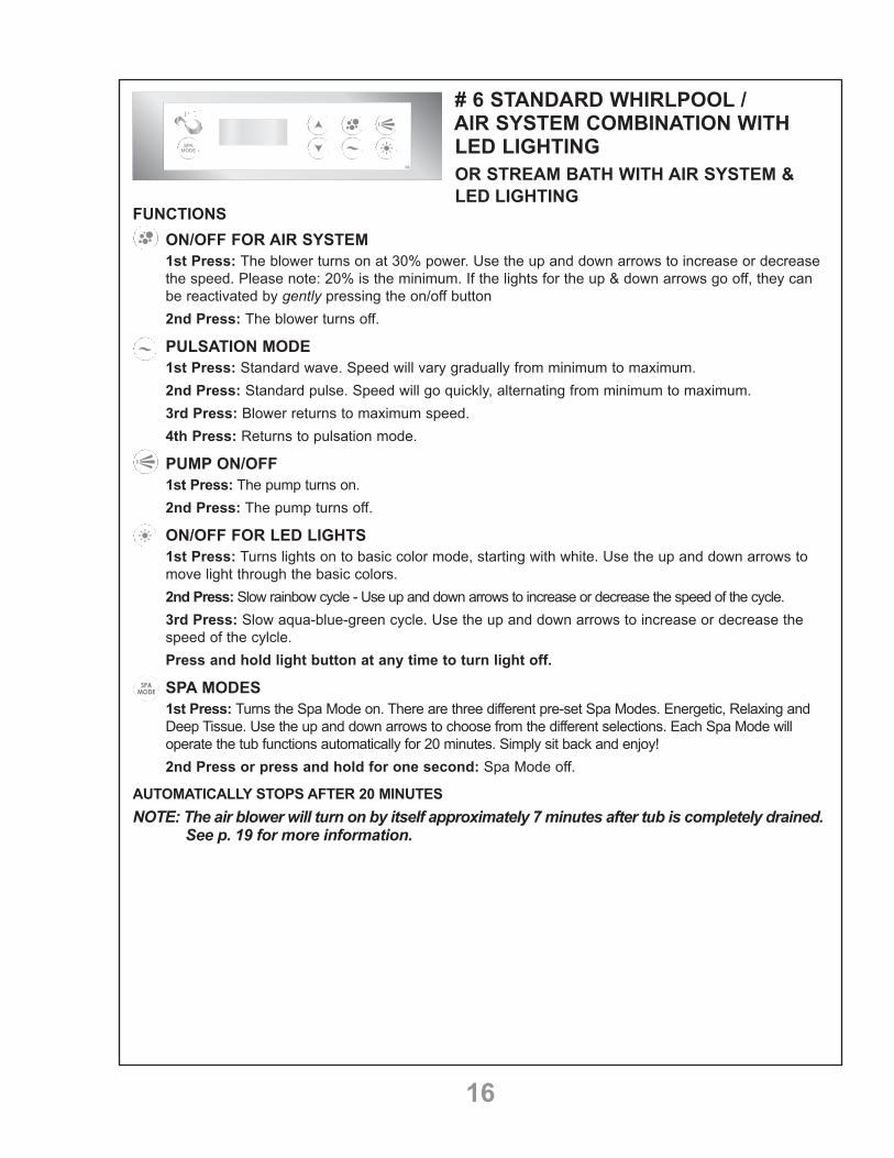
# 6 STANDARD WHIRLPOOL / AIR SYSTEM COMBINATION WITH LED LIGHTING
FUNCTIONS
ON/OFF FOR AIR SYSTEM1st Press: The blower turns on at 30% power. Use the up and down arrows to increase or decrease the speed. Please note: 20% is the minimum. If the lights for the up & down arrows go off, they can be reactivated by gently pressing the on/off button2nd Press: The blower turns off.
PULSATION MODE1st Press: Standard wave. Speed will vary gradually from minimum to maximum. 2nd Press: Standard pulse. Speed will go quickly, alternating from minimum to maximum.3rd Press: Blower returns to maximum speed. 4th Press: Returns to pulsation mode.
PUMP ON/OFF1st Press: The pump turns on. 2nd Press: The pump turns off.
ON/OFF FOR LED LIGHTS1st Press: Turns lights on to basic color mode, starting with white. Use the up and down arrows to move light through the basic colors.2nd Press: Slow rainbow cycle - Use up and down arrows to increase or decrease the speed of the cycle.3rd Press: Slow aqua-blue-green cycle. Use the up and down arrows to increase or decrease the speed of the cylcle.Press and hold light button at any time to turn light off.
SPA MODES1st Press: Turns the Spa Mode on. There are three different pre-set Spa Modes. Energetic, Relaxing and Deep Tissue. Use the up and down arrows to choose from the different selections. Each Spa Mode will operate the tub functions automatically for 20 minutes. Simply sit back and enjoy!2nd Press or press and hold for one second: Spa Mode off.
AUTOMATICALLY STOPS AFTER 20 MINUTESNOTE: The air blower will turn on by itself approximately 7 minutes after tub is completely drained. See p. 19 for more information.
OR STREAM BATH WITH AIR SYSTEM &LED LIGHTING

17
# 8 ULTRA THERAPY WHIRLPOOL / AIR SYSTEM COMBINATION
FUNCTIONS
ON/OFF PUMP FOR POINT-MASSAGE JETS1st Press: The pump starts. LED light on.2nd Press: The pump stops. LED light off.
ON/OFF PUMP FOR MICRO-JETS / TSUBO MASSAGEIMPORTANT! YOU MUST TURN THE VOLUME CONTROL FOR THE MICRO-JETS DOWN UNTIL YOU ARE SITTING IN FRONT OF THEM. IF ACTIVATED BEFORE, WATER MAY SPLASH OUTSIDE THE BATH.
1st Press: The Tsubo pump starts. LED light on.Press & hold 1 second: The Tsubo pump stops. LED light off.Press & hold 3 seconds: The Tsubo sequential pulse mode starts. LED will flash. The sequential pulse mode automatically advances the system through the seven operational Tsubo modes every 10 seconds.
TSUBO MODE/SPEED CONTROLTsubo: Press to change the Tsubo pump (micro-jets) through the seven different operational modes. Not available when the Tsubo is in sequential pulse mode.Blower: Press & hold up or down arrow to increase or decrease the blower speed. Release pres-sure at the desired speed.Note: The up and down arrows will operate the last function button activated. (Tsubo pump or blower.)
ON/OFF - BLOWER1st Press: The blower starts. LED light on.Press & Hold 1 second - The blower stops. LED light off.Press & Hold 3 seconds - Wave - Speed will vary gradually from maximum to minimum. Light will flash quickly.Press & Hold for 6 seconds - Pulse - Speed will go directly to minimum and then straight back to maximum. Light will flash slowly.
SEQUENTIAL PULSE MODE - FOR MICRO-JETSThe sequential pulse mode automatically advances the system through the seven different Tsubo modes every 10 seconds, when selected. To select this mode activate the micro jets; press and hold the Tsubo Mode button / up arrow for 3 seconds. To cancel, press button up or down arrow on the keypad.
AUTOMATICALLY STOPS AFTER 20 MINUTES
NOTE: This system is equipped with a Tsubo lock-out protection mode for the micro-jets. See p. 19 for more information.
OR STREAM BATH WITH AIR SYSTEM &LED LIGHTING

18
# 9 ULTRA THERAPY WHIRLPOOL / AIR SYSTEM COMBINATION WITH LED LIGHTING
FUNCTIONS
ON/OFF FOR AIR SYSTEM1st Press: The blower turns on at 30% power. Use the up and down arrows to increase or decrease the speed. Please note: 20% is the minimum. If the lights for the up & down arrows go off, they can be reactivated by gently pressing the on/off button2nd Press: The blower turns off.
WHIRLPOOL PUMP ON/OFF - LARGE POINT-MASSAGE JETS1st Press: The pump turns on. Use the air volume control to adjust the pressure felt from the jets.2nd Press: The pump turns off.
ON/OFF FOR MICRO-JETS / TSUBO MASSAGEIMPORTANT! YOU MUST TURN THE VOLUME CONTROL FOR THE MICRO-JETS DOWN UNTIL YOU ARE SITTING IN FRONT OF THEM. IF ACTIVATED BEFORE, WATER MAY SPLASH OUTSIDE THE BATH.
1st Press: Turns the micro-jets on full power. Adjust the flow from the jets by turning the cluster control knobs. Use the up / down arrows to pass to the next of 7 pulsation modes. If the light on the arrows turns off, gently press the on/off button to reactivate them.2nd Press: Pump is in pulse mode and will automatically advance to the next pulsation mode every 10 seconds.3rd Press or press and hold for 1 second: Pump off. The pump has an auto shut off after 15 min-utes and a lock out timer. See "Additional System Information" on next page.
ON/OFF FOR LED LIGHTS1st Press: Turns lights on to basic color mode, starting with white. Use the up and down arrows to move light through the basic colors.2nd Press: Slow rainbow cycle - Use up and down arrows to increase or decrease the speed of the cycle.3rd Press: Slow aqua-blue-green cycle. Use the up / down arrows to adjust the speed of the cycle. If the lights for the up /down arrows go off, they can be reactivated by gently pressing the on/off button. Press and hold light button at any time to turn light off. SPA MODES1st Press: Turns the Spa Mode on. There are three different pre-set Spa Modes. Energetic, Relaxing and Deep Tissue. Use the up and down arrows to choose from the different selections. Each Spa Mode will operate the tub functions automatically for 20 minutes. Simply sit back and enjoy!2nd Press or press and hold for one second: Spa Mode off.
SEQUENTIAL PULSE MODE - FOR MICRO-JETSThe sequential pulse mode automatically advances the system through the seven different Tsubo modes every 10 seconds, when selected. To select this mode activate the micro jets; press and hold the Tsubo Mode button / up arrow for 3 seconds. To cancel, press button up or down arrow on the keypad.
AUTOMATICALLY STOPS AFTER 20 MINUTESNOTE: The air blower will turn on by itself approximately 7 minutes after tub is completely drained. The system is also equipped with a Tsubo lock-out protection mode for the micro-jets. See p. 19 for more information.

19
ADDITIONAL SYSTEM INFORMATIONTSUBO LOCK-OUT TIMER - SYSTEMS #5, #8 AND #9 The user is allowed to operate the Tsubo mode for a total of 30 minutes (two 15-minute cycles) before a lock-out of the Tsubo mode occurs. This is designed to avoid tripping the thermal protector in the motor. The details of the lock-out are as follows:
• A total of two 15-minute cycles results in the Tsubo mode being locked out for two hours of cool-down time. 1 minute of Tsubo mode = 4 minutes of cool down time (cumulative).
• When the lock-out function is active, the micro-jets can still be operated at high speed, but the lock-outcountdown is suspended while the micro-jets are running. The required cooling off period resumes whenthe Tsubo pump is turned completely off.
• When the Tsubo pump is running, the user is notified that the lock-out condition has occurred by the fastflashing of the Tsubo button LED (#3) when the Tsubo mode button is pressed. The motor remains onhigh speed. The user can still control the pressure of the micro-jets by using the volume control knob.
• The cumulative cool-down function allows for 1 additional minute of Tsubo mode operation for every4 minutes of cool-down time.
• The lock-out function is reset each time the power to the control is turned off, and then back on again.
AUTOMATIC PURGE / DRYING CYCLE - SYSTEMS #1, #3, #4, #6, #8 AND #9Each MTI air system is equipped with two sensors on the floor of the bath near the drain. Every time water is introduced to the bath and drained, either by showering, bathing or cleaning, the sensors will activate the purge/drying cycle. The cycle will start approximately 7 minutes after the bath is drained and run for 1 minute. The purge cycle will activate even when the air bath has not been turned on. To cancel the purge, once it begins, simply press the on/off button for the air system. This will delay the purge for 7 minutes. Pressing the on/off button to delay the purge a second time will cancel the purge until the next use.
24 hour purge cycle - The system will purge once every 24 hours at the time the cycle is first activated (for example, if you activate the purge cycle at 10:00 am, the bath will purge each day at 10:00 am).
Activate by pressing the "+" button or "up" arrow on the keypad for 5 seconds. The keypad will flash once. To deactivate, simply press the button again for 5 seconds and the normal purge cycle will resume. The keypad will flash twice.
Manual stop: if the blower button is pressed during the 1 minute drying cycle, the cycle will stop and will restart 24 hours later at the programmed time.In the event of a power disruption or brown out, the program will be automatically deactivated. Reset 24 hour purge.
In case there is water in the tub when the 24 hour purge is supposed to start, the purge will not come on and disturb the bather. 7 minutes after water has drained, the normal purge will begin. After the purge cycle, the system reverts back to 24 hour purge.
20
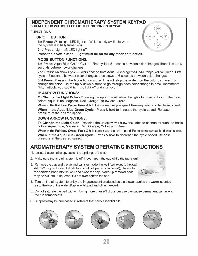
INDEPENDENT CHROMATHERAPY SYSTEM KEYPADFOR ALL TUBS WITHOUT LED LIGHT FUNCTION ON KEYPADFUNCTIONS
ON/OFF BUTTON:1st Press: White light. LED light on (White is only available when the system is initially turned on).2nd Press: Light off. LED light off.Press the on/off button - Light must be on for any mode to function.
MODE BUTTON FUNCTIONS:1st Press: Aqua-Blue-Green Cycle. - First cycle 1.5 seconds between color changes; then slows to 6 seconds between color changes.2nd Press: Rainbow Cycle - Colors change from Aqua-Blue-Magenta-Red-Orange-Yellow-Green. First cycle 1.5 seconds between color changes; then slows to 6 seconds between color changes. 3rd Press: Pressing the Mode button a third time will stop the system on the color displayed.To change the color, use the up & down buttons to go through each color change in small increments. (Alternatively, you could turn the light off and start over.)
UP ARROW FUNCTIONS: To Change the Light Color - Pressing the up arrow will allow the lights to change through the basic colors: Aqua, Blue, Magenta, Red, Orange, Yellow and Green. When in the Rainbow Cycle - Press & hold to increase the cycle speed. Release pressure at the desired speed. When in the Aqua-Blue-Green Cycle - Press & hold to increase the cycle speed. Release pressure at the desired speed.
DOWN ARROW FUNCTIONS: To Change the Light Color - Pressing the up arrow will allow the lights to change through the basic colors: Aqua, Blue, Magenta, Red, Orange, Yellow and Green. When in the Rainbow Cycle - Press & hold to decrease the cycle speed. Release pressure at the desired speed. When in the Aqua-Blue-Green Cycle - Press & hold to decrease the cycle speed. Release pressure at the desired speed.
AROMATHERAPY SYSTEM OPERATING INSTRUCTIONS 1. Locate the aromatherapy cap on the top flange of the tub.
2. Make sure that the air system is off. Never open the cap while the tub is on!
3. Remove the cap and the vented canister inside the well (see image to the right). Add 2-3 drops of essential oils to a small felt pad (not included), place into the canister, back into the well and close the cap. Make-up removal pads may be cut into 1" squares. Do not over tighten the cap.
4. Turn on the air system to enjoy the fragrant scent produced as the blower carries the warm, scented air to the top of the water. Replace felt pad and oil as needed.
5. Do not saturate the pad with oil. Using more than 2-3 drops per use can cause permanent damage to the tub components.
6. Supplies may be purchased at retailers that carry essential oils.

21
WHIRLPOOL OPERATING INSTRUCTIONS1. MTI whirlpool tubs are equipped with a factory installed on/off device. This eliminates the need
for an external switch. Starting motor with no water in the tub could result in damage to the pump and internal seals and could void your warranty.
2. Fill tub approximately 1" above highest jet. Do not start pump until tub has been filled to specified level.Do not leave a filling or full tub unattended.
3. When you are ready to use the whirlpool system, activate the on/off device on the deck of the tub.(For whirlpools or air bath / whirlpool combos equipped with a keypad, please see pages 11-19 forcontrol photos and functions for your particular model.)
4. Adjust the amount of air mixed with the water using the master air volume control located on thedeck or side-wall of the tub. Rotate the control counter-clockwise to increase the amount of airand pressure in the system. If your tub is equipped with a cleaning system, the detergent dis-penser is also the air volume control.
5. All jets on MTI Designer Collection whirlpools are designed to operate individually. Open or close jetsby either pushing and pulling the nozzle or twisting the jet nozzle, depending on jet style.
6. Hydrotherapy jets can also be adjusted directionally.
7. If your tub is equipped with 4 or more micro-jets, it will also be equipped with a volume control divertervalve to adjust pressure and shut off the micro-jets. (See diagram on page 22).
IMPORTANT! YOU MUST TURN THE VOLUME CONTROL FOR THE MICRO-JETS DOWN UNTIL YOUARE SITTING IN FRONT OF THEM. IF ACTIVATED BEFORE, WATER MAY SPLASH OUTSIDE THE BATH.8. Bath oils or other petroleum-based products are not recommended for use in MTI whirlpool tubs.
These products have been shown to increase the possibility of bacteria growth within the system.
9. Bubble bath should only be used sparingly. The action of the system will greatly increase the amountof bubbles. The system must also be cleaned after each use as described in “Cleaning Instructions.”
10. The use of products containing natural or artificial coloring or dyes may cause discoloration of jetsand / or controls.
11. If your tub is equipped with an inline heater, the heater will come on each time the point- massage (large jets) are operating. There is no separate on/off device. The inline heater is notdesigned to heat cold water; it is designed to help maintain the temperature of the bath. Theheater has a pre-set, non-adjustable thermostat set to 102°F.
22
OPTIONAL EQUIPMENT OPERATING INSTRUCTIONS INLINE HEATER For Whirlpools - The factory installed inline heater used on MTI whirlpool systems is designed to maintain the temperature of the water during the hydrotherapy bath. The heater is not designed to heat cold water. The heater will activate automatically when the pump is engaged. There is no separate control for the heater. The thermostat is pre-set at 102°F. The heater must be plugged into a110 VAC,15 AMP, GFCI protected outlet. Both the pump and inline heater must be plugged in for system to operate properly. The heater has an indicator light to confirm that it is working.For Soakers and Air Baths - The inline heating system for soaking tubs and air baths is manually activated by an on/off device, typically a push button style. This system gently recirculates the bath water through the inline heater, with negligible disturbance to the water. The heatsoak system requires a dedi-cated 110 VAC, 20 AMP, GFCI protected outlet. Both the pump and inline heater must be plugged in for system to operate properly.
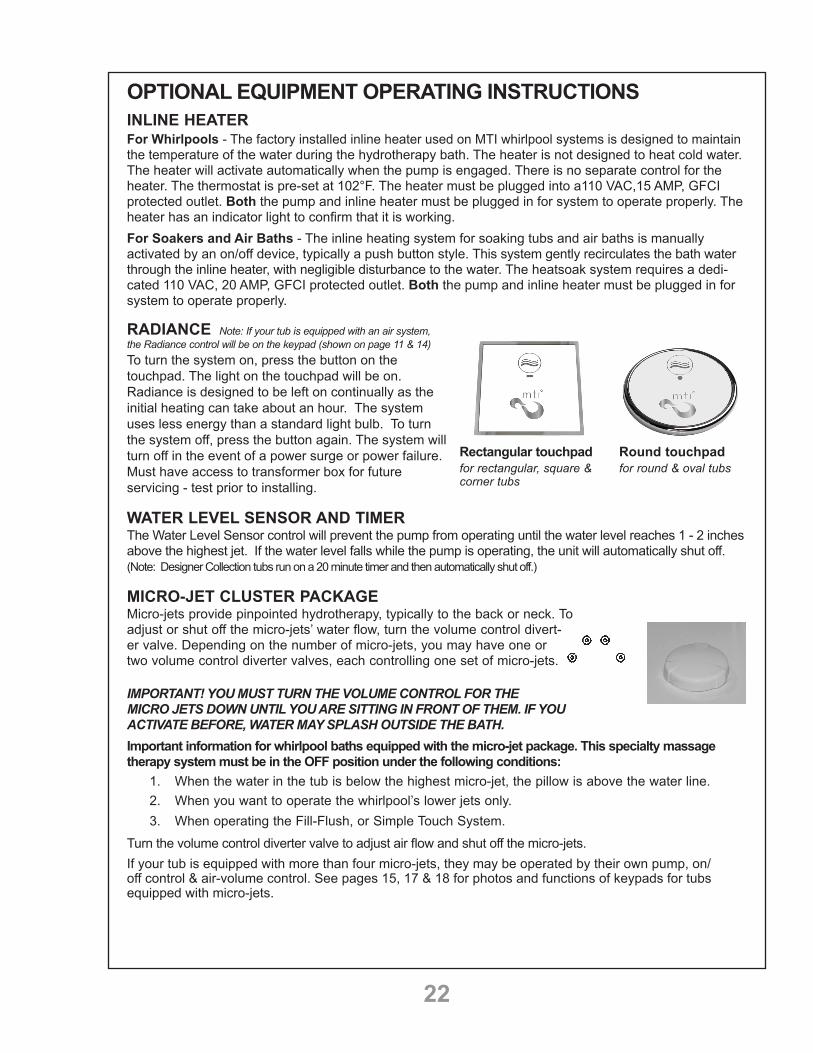
RADIANCE Note: If your tub is equipped with an air system, the Radiance control will be on the keypad (shown on page 11 & 14)To turn the system on, press the button on the touchpad. The light on the touchpad will be on. Radiance is designed to be left on continually as the initial heating can take about an hour. The system uses less energy than a standard light bulb. To turn the system off, press the button again. The system will turn off in the event of a power surge or power failure. Must have access to transformer box for future servicing - test prior to installing.
WATER LEVEL SENSOR AND TIMERThe Water Level Sensor control will prevent the pump from operating until the water level reaches 1 - 2 inches above the highest jet. If the water level falls while the pump is operating, the unit will automatically shut off. (Note: Designer Collection tubs run on a 20 minute timer and then automatically shut off.)
MICRO-JET CLUSTER PACKAGEMicro-jets provide pinpointed hydrotherapy, typically to the back or neck. To adjust or shut off the micro-jets’ water flow, turn the volume control divert-er valve. Depending on the number of micro-jets, you may have one or two volume control diverter valves, each controlling one set of micro-jets. IMPORTANT! YOU MUST TURN THE VOLUME CONTROL FOR THE MICRO JETS DOWN UNTIL YOU ARE SITTING IN FRONT OF THEM. IF YOU ACTIVATE BEFORE, WATER MAY SPLASH OUTSIDE THE BATH.Important information for whirlpool baths equipped with the micro-jet package. This specialty massage therapy system must be in the OFF position under the following conditions:
1. When the water in the tub is below the highest micro-jet, the pillow is above the water line.2. When you want to operate the whirlpool’s lower jets only.3. When operating the Fill-Flush, or Simple Touch System.
Turn the volume control diverter valve to adjust air flow and shut off the micro-jets.If your tub is equipped with more than four micro-jets, they may be operated by their own pump, on/off control & air-volume control. See pages 15, 17 & 18 for photos and functions of keypads for tubs equipped with micro-jets.
Rectangular touchpad for rectangular, square & corner tubs
Round touchpad for round & oval tubs

23
FILL-FLUSH SYSTEM OPERATING INSTRUCTIONSTHE WHIRLPOOL SYSTEM SHOULD BE CLEANED PERIODICALLY. MTI BATHS RECOMMENDS CLEANING AT LEAST ONCE A MONTH, NOT TO EXCEED 90 DAYS BETWEEN CLEANINGS. ALWAYS USE CAUTION WHEN USING CHLORINE-BASED PRODUCTS IN CONJUNCTION WITH OTHER CLEANING PRODUCTS. THE POSSIBILITY OF HARMFUL FUMES COULD RESULT. ALWAYS RINSE THOROUGHLY.DO NOT LEAVE THE UNIT UNATTENDED DURING FILL-FLUSH OPERATIONS.NOTE: If your tub is not equipped with the optional Fill-Flush system, please see page 24 for cleaning instructions.TO FILL THE SYSTEM:
1. Make sure all jets are in the OPEN position by pulling or rotating the jet nozzle(depending on jet style).
2. Turn on hot and cold water to suit. Continue filling the tub to the desiredlevel (at least 2" above the highest jet) and enjoy your bath.Don’t forget to turn off the water!
TO FLUSH THE SYSTEM:1. After using the whirlpool system, drain tub of all water. CLOSE all of the
jet nozzles by simply pushing the jet nozzle in or twisting the jet nozzle(depending on jet style).
2. Unscrew the dispenser cap (generally located between the hot and coldhandles). Add one of the following: 2 ounces of MTI Fresh Wave Cleaner,1 cup vinegar or several drops of a low sudsing detergent mixed with 1 cupof warm water. For each method, follow with one cup of cool, clean water.Replace cap and turn on hot and cold water. Do not turn on pump. Thisallows water and detergent to circulate through the air line, water line andpump. Let run for 2-3 minutes. Residue will be flushed out the suction intakeand down the drain. NOTE: It is normal for some water to be coming out ofthe jets as well as the area around the jet nozzle.
3. Turn off water, open the jets and allow remaining water to flow out of the jets.
BASIC CLEANING INSTRUCTIONS FOR SINGLE PUMP SYSTEMS WITH FULL-SIZE JETS AND MICRO-JET COMBINATIONS USING THE FILL-FLUSH SYSTEM.
1. Close all full-size jets by pushing in nozzle or turning the jet nozzle (depending on jet design).2. Close all deck-mounted or wall-mounted micro-jet control valves.3. Remove detergent dispenser cap.
4. Add one of the following into the detergent dispenser: 2 oz. of MTI Fresh Wave Cleaner, 1 cup ofvinegar or a few drops of a low-sudsing liquid detergent mixed with 1 cup of warm water. For eachmethod, follow with 1 cup of cool, clean water.
5. Replace the detergent dispenser cap.6. Turn on water. Water mixes with cleaning solution and flows from air line to water line, through
pump, out the suction and down the drain.7. Allow water to run for three minutes.8. Open all deck-mounted or wall-mounted micro-jet control valves.9. Allow water to run for one more minute.10. Open all full-size jets and allow water to run for 30 seconds.11. Turn off water.

24
SIMPLE TOUCH SYSTEM OPERATING INSTRUCTIONS1. After bathing, drain the bath as usual, leaving the drain open.
2. Close all point-massage and rotary jets.
3. Remove detergent dispenser cap.
4. Add one of the following into the detergent dispenser: 2 oz. of MTI Fresh Wave Cleaner, 1 cup ofvinegar or a few drops of a low-sudsing liquid detergent mixed with 1 cup of warm water. For eachmethod, follow with 1 cup of cool, clean water.
5. Replace the detergent dispenser cap.
6. Depress the on/off button, which activates the Simple Touch Cleaning System.
7. The Simple Touch Cleaning System will run for three minutes, circulating water and detergent through theair line, water line, and pump. Residue will then be flushed out the suction and down the drain. The clean-ing process will automatically shut off, leaving your whirlpool bath plumbing system sparkling clean.
8. After the system shuts off, open the jets.
BASIC CLEANING INSTRUCTIONS FOR SINGLE PUMP SYSTEMS WITH FULL-SIZE JETS AND MICRO-JET COMBINATIONS USING THE SIMPLE TOUCH SYSTEM.
1. Close all full-size jets by pushing in nozzle or turning face plate (depending on jet design).
2. Close all deck-mounted or wall-mounted micro-jet control valves.
3. Remove detergent dispenser cap.
4. Add one of the following into the detergent dispenser: 2 oz. of MTI Fresh Wave Cleaner, 1 cup ofvinegar or a few drops of a low-sudsing liquid detergent mixed with 1 cup of warm water. For eachmethod, follow with 1 cup of cool, clean water.
5. Replace the detergent dispenser cap.
6. Push Simple Touch button to activate. Water mixes with cleaning solution and flows from air lineto water line, through pump, out the suction and down the drain.
7. The system will run for approximately three minutes.
8. Open all deck-mounted or wall-mounted micro-jet control valves.
9. Again, push Simple Touch button to activate. Allow water to flow for approximately two minutes.
10. Open all full-size jets and allow water to run for the remainder of the Simple Touchthree minute cycle.

25
CLEANING INSTRUCTIONS FOR WHIRLPOOL SYSTEMS NOT EQUIPPED WITH THE OPTIONAL FILL-FLUSH OR SIMPLE TOUCH CLEANING SYSTEMSTHE WHIRLPOOL SYSTEM SHOULD BE CLEANED PERIODICALLY. MTI BATHS RECOMMENDS CLEANING AT LEAST ONCE A MONTH, NOT TO EXCEED 90 DAYS BETWEEN CLEANINGS. ALWAYS USE CAUTION WHEN USING CHLORINE-BASED PRODUCTS IN CONJUNCTION WITH OTHER CLEANING PRODUCTS. THE POSSIBILITY OF HARMFUL FUMES COULD RESULT. ALWAYS RINSE THOROUGHLY.
Fill tub with warm water 2" above the highest jet and add one of the following to the bath water: 1/4 cup of MTI’s Fresh Wave Cleaning Solution, 1 cup vinegar, or several drops of a low sudsing detergent mixed with 1 cup warm water then followed with 1 cup of cool, clean water. Turn the system on for five minutes then let stand for an additional 15 minutes. Drain the tub and refill with cold water. Restart the system for 10 minutes, then drain. If standard cleaning does not remove stubborn build-up or tough stains, your jets can be easily removed with pliers for more thorough cleaning. Soak jets overnight in a pan filled with warm water and mild dish soap, and scrub lightly with a soft bristled brush or place on top rack in dish-washer, being careful to remove before drying cycle starts. Whirlpools with the optional Fill-Flush System or Simple Touch System should refer to page 22 and 23 of this booklet for operating and cleaning instructions.
CLEANING INSTRUCTIONS FOR THE ACRYLIC SHELLThe cross-linked cast acrylic surface of all MTI acrylic products is among the glossiest, highest quality surfac-es available. Its hard, non-porous surface prevents dirt from accumulating and resists stains better than other materials. With normal use, cast acrylic will retain its beauty with only a minimal amount of care. To maintain the high gloss, elegant look of the cast acrylic surface, follow these simple steps:
Use common household, non-abrasive cleaners for most cleaning jobs (for example: a mild dishwashing detergent such as Ivory Liquid). Follow manufacturer’s directions and precautions. Do not use unless the product label specifically states that it is safe for acrylic. Rinse well and dry with a soft, clean cloth. Be sure to check the product label. Some products, although not containing abrasives, WILL dam-age the acrylic over time.
Never use any type of “scrubbing bubbles” or aerosol spray cleaners on your acrylic product unless it specifically states that it is safe for use on acrylic! Never use abrasive cleansers. If any product feels gritty when rubbed between your fingers, do not use on the acrylic surface or controls as permanent damage will occur.
Do not allow your cast acrylic surface to come into contact with nail polish, nail polish remover, Winter-green oil, dry cleaning solution, lacquer thinners, gasoline, pine oil, etc.
Remove dust and dry dirt with a soft, damp cloth.
Clean grease, oil, paint or ink stains with isopropyl (rubbing) alcohol. Dry with a clean, soft cloth.
Avoid using razor blades or other sharp objects that might scratch the surface. Small scratches can be removed by applying a thin coat of automotive polishing liquid and buffing lightly with a clean cloth. For deeper scratches, sand the surface lightly with a 400 grit “wet or dry” paper and buff with a fine grit buffing compound.
MTI strongly recommends a professional acrylic repair person for deep scratches or chips.

26
TROUBLESHOOTINGQ: The pump or blower will not turn on. What should I check first?
A: Check the electrical connections. Test the outlet for power by plugging in a small lamp or hair dryer. Check to make sure the breaker is not tripped. Replace GFCI outlet or breaker if necessary. On systems with multiple control boxes or equipment, ensure that all connections are intact.
Q: There is a leak at the pump when it’s turned on. How do we stop the leak?
A: Check the rubber “O” rings for proper seating. Tighten the large union nut rings on the pump. These may have loosened during shipping or installation. Do not over tighten.
Q: The whirlpool jets do not seem to have much force. How can I adjust?
A: Open the air volume control on the top or side wall of the tub. If your tub is equipped with the Fill Flush or Simple Touch cleaning system, this is the same port you use for the cleaning solution. Micro-jets are regulated using the cluster control knob. Each group of micro-jets will have its own cluster control.
Q: One or two of my whirlpool jets are not working. What could be the problem?
A: Each jet can be opened and closed individually. Check each jet by turning the jet nozzle to ensure it’s open. Older tubs may have a push/pull style jet nozzle.
Q: How can I check that my in-line heater is working?
A: The in-line heater has a separate power cord. Make sure the pump and heater are both plugged into working receptacles. The indicator light on the top of the heater will glow, indicating it is functioning properly. Keep in mind, the in-line heater will not heat your water; it will just maintain the water temperature up to 103 degrees.
Q: There is a rust colored, greasy ring in my bath tub. What causes this?
A: The condition results from sediment in the water heater of the home. Drain and flush the heater according to the manufacturer’s instructions, and then clean the interior of the tub with a mild, grease cutting dish soap.
Q: The air jets on my tub are not blowing air bubbles. What could be the problem?
A: The keypad or other connections may have been unplugged during installation. Check that the keypad is connected to the blower, and the blower is plugged into a working receptacle. Check that the grey air hose from the air blower to the manifold is properly connected. If necessary, reconnect and tighten clamps.
Q. My MTI air bath appears to just turn on even if we are not in the tub.
A. Each MTI Designer Collection air bath is equipped with a pair of sensors near the drain of the bath. They appear as two small chrome buttons. Every time water is introduced into the bath, even if the air system was not used, the air system will automatically activate approximately 7 minutes after the water has drained out of the tub in order to purge the system of any small droplets of water. The system will turn off in approximately 1 ½ minutes. The light on your keypad blinks during the countdown to the purge cycle.
Q. I understand the purge cycle, however my tub is now purging in the middle of the night. How can I stop this from happening?
A. Small, barely detectable power fluctuations may have disrupted the purge cycle. Turn the breaker off (or unplug the blower), wait for ten seconds, then plug back in. The blower should now follow the normal purge cycle.
continued on next page

27
Q: The air bubbles seem cool. How do I check that the blower is warming the air?
A: To verify, turn the air system on high for 4-5 minutes (you do not need to have water in the tub). Carefully feel the grey air hose where it exits the blower. It should be warm to the touch. If it is cold, please contact MTI for service. Please note that some skin sensitive people might experience the so-called “cold air effect”, which is caused by the actual sensation of air bubbles running along the skin, giving the bather a “shivering” sensation. Note: Even if the air entering the tub was hot enough to burn the skin, this shivering effect would still persist. The heated blower is not designed to heat your bath water, just to preheat the incoming air.
If your tub is installed against an outside wall(s), it is recommended to adequately insulate the wall(s) to minimize heat loss. Do not insulate the blower itself; the blower needs sufficient air space surrounding it for proper circulation and operation.
Q. Can I relocate the pump and/or blower?
A. Because all MTI tubs are built to order, the pump and blower can be relocated during the manufacturing process (at no additional charge) to accommodate your specific installation. The whirlpool pump cannot be relocated once the tub is built. The air blower can be relocated on-site up to eight feet away from the bath.
Q. Is it safe to use bath salts or bath oils in my whirlpool?
A. Water soluble products such as bath salts are fine to use, however, MTI does not recom-mend the use of heavy bath oils. If bath oil is used, refer to the cleaning section of your manual for proper after care and cleaning instructions. Products containing strong natural or chemical dyes may discolor the jets and/or controls on your tub. Check the label to ensure the products are safe for acrylic or plastics, and always use according to the product recommendations.
Q. How can I get scratches out of my acrylic tub?
A. Most scratches can be buffed out using an automotive polish. Any polish suitable for use on "clear coated" automobile paint is fine. Deeper scratches and chips may require the services of a professional acrylic repair technician.
Q. My bath's hydrotherapy system has been working great for years, and now has stopped working. What should I check first?
A. The problem is most likely the breaker or the GFCI outlet under the tub. Check your breaker box first, and then use a hairdryer to test the outlet under your bath where the equipment is plugged in. This should identify the problem. If both these items check out fine, please have your registration number available and contact our technical service department.
Q. How do I find the serial or registration number on my bath?
A. The registration number can be found on a silver sticker attached to the outside wall of your bath. It is typically placed 3-4 inches over the pump and /or air blower.

28Continued on next page
M T I L I F E T I M E L I M I T E D R E S I D E N T I A L W A R R A N T Y
MTI WHIRLPOOL, AIR TUB AND SOAKING TUB RESIDENTIAL WARRANTYThis warranty is effective for all MTI acrylic whirlpools, air tubs, soaking tubs manufactured after January 1, 2006, and is in lieu of all other warranties. MTI Baths (MTI) provides a limited warranty on its products for use in the continental United States of America* to original purchasers for personal or single family use. Warranty coverage begins on date of purchase (regardless of installation date). Tubs are warranted only when installed in an indoor climate-controlled environment according to the instructions contained in our manual. Previously used display or floor models do not carry any warranty coverage.
Whirlpool, Soaking, Stream Bath & Air Tub Warranty: MTI warrants our Designer Collection whirlpool and soaking tub products for life. The non pro-rated warranty covers the tub shell and most standard factory-installed components, including pump, motor and standard plumbing against defects in material or workmanship. All other components, even those included in MTI packages are subject to the MTI Two-Year parts warranty described below. Components covered for parts only include, but are not limited to, on/off controls, transformer boxes, neck jet pillows, low water sensors, solenoid valves & LED lights. MTI warrants all Designer Collection air tubs with Air Massage thermo-air massage system for life. The warranty covers the tub shell and blower. All controls and mechanisms are subject to the MTI Two-Year Parts only warranty described below. The bath must be water tested for operation and leaks prior to final enclosure of the unit. Failure to do so will void warranty. If a problem is discovered after the final enclosure, MTI will not be responsible for the cost of removing or reinstalling the tub, or for costs associated with any adjacent materials. Proper drain installation is the responsibility of the installer. MTI’s warranty does not cover drain leakage.Two-Year (Parts Only) Warranty: MTI warrants all other components not specified above for two years for parts only against defects in material or workmanship. Components covered for parts only include, but are not limited to, on/off controls, transformer boxes, neck jet pillows, low water sensors, solenoid valves & LED lights. Replacement parts shall assume the remaining warranty period of the parts replaced. Replacement parts are subject to availability, and may differ from those originally supplied. MTI cannot guarantee that parts currently in use will be available in the future. Changes in materials, parts or specifications are not valid reasons for product refusal or replacement under warranty claims. Grab bars and additional/special order trims are specifically excluded from this warranty. Valves and accessories installed and sold by MTI carry their own warranty from their original manufacturer. MTI does not warrant valves and accessories. Check with MTI for details.
Radiance® Warranty: MTI warrants Radiance for two years, parts only, against manufacturing defects. If the control box or keypad fails within the two year period, MTI will send replacement parts out at no charge. In the unlikely event that the electrical heating grid fails within the two year period, MTI Baths’ only obligation is to refund the purchase price of the Radiance system to the original product owner. Proof of purchase required.
Stereo H2O® Warranty: MTI warrants the transducer(s) for one year against manufacturing defects to the original product owner. Labor or any costs associated with gaining access for repair are specifically excluded from warranty. Proof of purchase required.
Return of Warranty Card: The warranty registration card must be filled out by the purchaser and mailed to MTI Baths within one hundred twenty days from purchase in order for this warranty to take effect. Or register online at mtibaths.com/contact-us/.
Warranty Limitations: The warranty is void if unit is not water tested for operation and leaks and inspected prior to final enclosure. The MTI warranty does not cover defects, damage, or failure caused by common carrier, installer, user, or other person.
Chips, cracks, and scratches are damages, and are NOT covered under warranty, however, they may be repaired by a qualified technician at the owner’s/user’s expense. Damages or defects that should be detected before installation are not covered.
29
MTI Baths is NOT liable for incidental or consequential damage, loss of time, inconvenience, incidental expenses or material charges or any other costs related to the application of this warranty.MTI does not cover the following: careless handling; modification of any type for any reason; improper installation (See Installation Instructions); connections supplied by the installer; improper voltage supply/electrical modifications; misuse; incorrect or improper maintenance; incorrect or inadequate water use; use of improper cleaners; or extraordinary acts such as earthquakes, hurricanes, lightning, floods, hail, etc.
Extent of Warranty: This warranty extends only to the original consumer/purchaser of the MTI Baths product when purchased and originally installed within the boundaries of the continental USA*. The warranty terminates after transfer of ownership or if tub is installed or relocated outside the boundaries of the continental USA* by the original consumer/purchaser prior to the expiration of the warranty period. Display floor models and overstock sale units are excluded from this warranty. See commercial warranty for products used in commercial, rental or multi-family applications.
Warranty Performance: In the event of any malfunction or defect covered under the terms of this warranty, a Factory Authorized Service Agent of MTI Baths will repair the MTI product. To obtain service, contact the MTI Service Department for an agent in your area and issuance of a service order number. No work/payment will be made without an authorized service order number. There will be no charge for parts, labor or freight costs for parts necessary to repair the tub under warranty. Written notice of any malfunction or defect must be given within ten days of the time the malfunctions were discovered, and must be accompanied by the tub serial number, model number and manufacturer’s date to verify purchase date. Notice must be given to: MTI Baths, 670 N. Price Rd., Sugar Hill, GA 30518, Attn: Service Dept. MTI reserves the right to inspect the malfunction or defect on site and determine appropriate course of action.
Acts Invalidating Warranty: Inspecting the unit prior to installation is the responsibility of the installer(s) or person(s) acting on behalf of the user. He/she is responsible for ensuring that the unit is free of defect or damage. The shipping container includes a note that advises the installer of this responsibility. MTI is not responsible for failure or damage that should have been discovered, repaired, and avoided by proper inspection and testing prior to installation. Damage that occurred in transit is the responsibility of the carrier. The consignee must open and inspect the unit for damage when it is delivered. If the unit is damaged, this must be reported immediately in writing to both the seller and the carrier and an inspection must be requested. In the event that the carrier fails to respond, report such response to both the seller and the carrier. Any freight claims must be filed within ten business days. It is the responsibility of the installer, contractor, or user to install/bed the unit properly and allow for access for service. Access must be provided to each pump and/or electrical component on the tub. The access panel(s) must have a minimum size of 16"x14" for installation and future servicing of the equipment. MTI Baths, Inc. will not authorize any service unless clear access is available. Access from a crawlspace or incomplete access to all equipment may result in warranty claims being denied. Unit must be water tested for operation and leaks prior to final enclosure. Damage, including chips or scratches, occurring to the unit during installation is the responsibility of the installer and after installation is the responsibility of the user.
Disclaimers: MTI Baths is not responsible for incidental or consequential damages/losses from any cause such as water damage to carpeting, floors, or ceilings. Optional equipment not manufactured by MTI or installed by MTI is not covered. Damages or defects that should be detected before installation are not covered. This limited warranty does not include labor, transportation, or other costs incurred in the removal and/or reinstallation of the original unit or replacement unit. Costs related to obtaining access for repair are not covered. The foregoing warranty is EXCLUSIVE and in lieu of all other warranties, including any other warranty of quality, express or implied, and including any warranty of merchantability, or any warranty of fitness for any particular purpose.
Customer Service: To verify coverage or request service, please contact the MTI service department at 800-783-8827. Please have serial or registration number available.* Exceptions for Alaskan and Canadian Customers: MTI Baths extends the complete Residential Limited Lifetime Warranty to any applicable product installed within a 75-mile radius of an Authorized MTI Distributor. Any installation site outside the 75-mile radius will be covered for two years, parts only.* Exceptions for Hawaiian Customers: MTI Baths extends the complete Residential Limited Lifetime Warranty to Hawaiian customers on the islands of Maui, Kauai and Oahu only. All other locations will be covered for two years, parts only.
30
Continued on next page
M T I C O M M E R C I A L W A R R A N T YMTI WHIRLPOOL, AIR TUB AND SOAKING TUB COMMERCIAL WARRANTY
This warranty is effective for all MTI acrylic whirlpools, air tubs, soaking tubs manufactured after February 1, 2006, and is in lieu of all other warranties. Warranty coverage begins on date of purchase (regardless of installation date). MTI Baths, Inc. provides a limited warranty to the original purchaser for commercial, rental or multi-family applications. Tubs are warranted only when installed in a climate-controlled environment according to the instructions contained in our manual. Previously used display or floor models do not carry any warranty coverage.
Whirlpool, Soaking, Stream Bath & Air Tub Warranty: MTI warrants our Designer Collection whirlpool and soaking tub products for 2 years. The non pro-rated warranty covers the tub shell and most standard factory-installed components, including pump, motor and standard plumbing against defects in material or workmanship. All other components, even those included in MTI packages are subject to the MTI One-Year parts warranty described below. Components covered for parts only include, but are not limited to, on/off controls, transformer boxes, neck jet pillows, low water sensors, solenoid valves & LED lights. MTI warrants all Designer Collection air tubs with Air Massage thermo-air massage system for 2 years. The warranty covers the tub shell and blower. All controls and mechanisms are subject to the MTI One-Year Parts only warranty described below. The bath must be water tested for operation and leaks prior to final enclosure of the unit. Failure to do so will void warranty. If a problem is discovered after the final enclosure, MTI will not be responsible for the cost of removing or reinstalling the tub, or for costs associated with any adjacent materials. Proper drain installation is the responsibility of the installer. MTI’s warranty does not cover drain leakageOne-Year (Parts Only) Warranty: MTI warrants options, accessories and all other components not specifically listed above for one year for parts only against defects of material or workmanship. Components covered for parts only include, but are not limited to: on/off controls, transformer boxes, neck jet pillows, low water sen-sors, solenoid valves & LED lights. Replacement parts shall assume the remaining warranty period of the parts replaced. Replacement parts are subject to availability, and may differ from those originally supplied. MTI can not guarantee that parts currently in use will be available in the future. Changes in materials, parts or specifications are not valid reasons for product refusal or replacement under warranty claims. Grab bars and additional/special order trims are specifically excluded from this warranty. Valves and accessories installed and sold by MTI carry their own warranty from their original manufacturer. MTI does not warrant valves and accessories. Check with MTI for details.
Radiance® Warranty: MTI warrants Radiance for two years, parts only, against manufacturing defects. If the control box or keypad fails within the two year period, MTI will send replacement parts out at no charge. In the unlikely event that the electrical heating grid fails within the two year period, MTI Baths’ only obligation is to refund the purchase price of the Radiance system to the original product owner. Proof of purchase required.
Stereo H2O® Warranty: MTI warrants the transducer(s) for one year against manufacturing defects to the origi-nal product owner. Labor or any costs associated with gaining access for repair are specifically excluded from warranty. Proof of purchase required.
Return of Warranty Card: The warranty registration card must be filled out by the purchaser within one hun-dred twenty days from purchase and mailed to MTI Baths in order for this warranty to take effect. Or register online at mtibaths.com/contact-us/.
Warranty Limitations: The warranty is void if unit is not water tested for operation and leaks and inspected prior to final enclosure. The MTI warranty does not cover defects, damage, or failure caused by common carrier, installer, user, or other person.
Chips, cracks, and scratches are damages, and are NOT covered under warranty, however, they may be repaired by a qualified technician at the owner’s/user’s expense. Damages or defects that should be detected before installation are not covered.
MTI Baths is NOT liable for incidental or consequential damage, loss of time, inconvenience, incidental expenses or material charges or any other costs related to the application of this warranty.

31
MTI does not cover the following: careless handling; modification of any type for any reason; improper installation (See Installation Instructions); connections supplied by the installer; improper voltage supply/electrical modifica-tions; misuse; incorrect or improper maintenance; incorrect or inadequate water use; use of improper cleaners; or extraordinary acts such as earthquakes, hurricanes, lightning, floods, hail, etc.
Extent of Warranty: This warranty extends only to the original consumer/purchaser of the MTI Baths product when purchased and originally installed within the boundaries of the continental USA (unless otherwise noted). The warranty terminates after transfer of ownership or if tub is installed or relocated outside the boundaries of the continental USA by the original consumer/purchaser prior to the expiration of the warranty period.
Warranty Performance: In the event of any malfunction or defect covered under the terms of this warranty, a Factory Authorized Service Agent of MTI Baths will repair the MTI product. To obtain service, contact the MTI Service Department for an agent in your area and issuance of a service order number. No work/payment will be made without an authorized service order number. There will be no charge for parts, labor or freight costs for parts necessary to repair the tub under warranty. Written notice of any malfunction or defect must be given within ten days of the time the malfunctions were discovered, and must be accompanied by the tub serial number, model number and manufacturer’s date to verify purchase date. Notice must be given to: MTI Baths, 670 N. Price Rd., Sugar Hill, GA 30518, Attn: Service Dept. MTI reserves the right to inspect the malfunction or defect on site and determine appropriate course of action.
Acts Invalidating Warranty: Inspecting the unit prior to installation is the responsibility of the installer(s) or person(s) acting on behalf of the user. He/she is responsible for ensuring that the unit is free of defect or damage. Our shipping container includes a notice that the installer of this responsibility. MTI is not responsible for failure or damage that should have been discovered, repaired, and avoided by proper inspection and testing prior to installation. Damage that occurred in transit is the responsibility of the carrier. The consignee must open and inspect the unit for damage when it is delivered. If the unit is damaged, this must be reported immediately in writing to both the seller and the carrier and an inspection must be requested. In the event that the carrier fails to respond, report such response to both the seller and the carrier. Any freight claims must be filed within ten business days. It is the responsibility of the installer, contractor, or user to install/bed the unit properly and allow for access for service. Access must be provided to each pump, air blower and/or electrical component on your tub. The access panel(s) must have a minimum size of 16"x14" for installation and future servicing of the equipment. MTI Baths, Inc. will not authorize any service unless clear access is available. Access from a crawlspace or incomplete access to all equipment may result in warranty claims being denied. Unit must be water tested for operation and leaks prior to final enclosure. Damage, including chips or scratches, occurring to the unit during installation is the responsibility of the installer and after installation is the responsibility of the user.
Disclaimers: MTI Baths is not responsible for incidental or consequential damages/losses from any cause such as water damage to carpeting, floors, or ceilings. Optional equipment not manu-factured by MTI or installed by MTI is not covered. Damages or defects that should be detected before installation are not covered. This limited warranty does not include labor, transportation, or other costs incurred in the removal and/or reinstallation of the original unit or replacement unit. Costs related to obtaining access for repair are not covered. The foregoing warranty is EXCLUSIVE and in lieu of all other warranties, including any other warranty of quality, express or implied, and including any warranty of merchantability, or any warranty of fitness for any particular purpose.
Customer Service: To verify coverage or request service, please contact the MTI service department at 800-783-8827. Please have serial or registration number available.

Manufactured by: MTI Baths, Inc.mtibaths.com670 N. Price RoadSugar Hill, GA 30518800 783 8827770 271 8228Fax 800 438 8827© Copyright 2015 by MTI Baths, Inc.Modification Rights Reserved.
Part # DSTUBWPAIR rev. 1215