
Installation and Operation Instructions for Pennant
60
Installation and Operation Instructions Document 1176B H2214400B Installation and Operation Instructions for Pennant ™ Hydronic Boiler Model PNCH Water Heater Model PNCV U.S. Reg. 2,765,423 WARNING If the information in this manual is not followed exactly, a fire or explosion may result causing property damage, personal injury or loss of life. Do not store or use gasoline or other flammable vapors and liquids in the vicinity of this or any other appliance. WHAT TO DO IF YOU SMELL GAS • Do not try to light any appliance. • Do not touch any electrical switch; do not use any phone in your building. • Immediately call your gas supplier from a nearby phone. Follow the gas supplier's instructions. • If you cannot reach your gas supplier, call the fire department. Installation and service must be performed by a qualified installer, service agency, or gas supplier. AVERTISSEMENT Assurez-vous de bien suivres les instructions données dans cette notice pour réduire au minimum le risque d’incendie ou d’explosion ou pour éviter tout dommage matériel, toute blessure ou la mort. Ne pas entreposer ni utiliser d’essence ni d’autres vapeurs ou liquides inflammables dans le voisinage de cet appareil ou de tout autre appareil. QUE FAIRE SI VOUS SENTEZ UNE ODEUR DE GAZ: • Ne pas tenter d’allumer d’appareils. • Ne touchez à aucun interrupteur. Ne pas vous servir des téléphones dansle bâtiment où vous vous trouvez. • Appelez immédiatement votre fournisseur de gaz depuis un voisin. Suivez les instructions du fournisseur. • Si vous ne pouvez rejoindre le fournisseur de gaz, appelez le sservice des incendies. L’installation et l’entretien doivent être assurés par un installateur ou un service d’entretien qualifié ou par le fournisseur de gaz. FOR YOUR SAFETY: This product must be installed and serviced by a professional service technician, qualified in hot water boiler installation and maintenance. Improper installation and/or operation could create carbon monoxide gas in flue gases which could cause serious injury, property damage, or death. Improper installation and/or operation will void the warranty. For indoor installations, as an additional measure of safety, Laars strongly recommends installation of suitable Carbon Monoxide detectors in the vicinity of this appliance and in any adjacent occupied spaces.
Transcript of Installation and Operation Instructions for Pennant

Installation and Operation Instructions Document 1176B
H22
1440
0B
Installation and OperationInstructions for
Pennant™
Hydronic BoilerModel PNCH
Water HeaterModel PNCVU.S. Reg. 2,765,423
WARNINGIf the information in this manual is notfollowed exactly, a fire or explosion mayresult causing property damage, personalinjury or loss of life.
Do not store or use gasoline or otherflammable vapors and liquids in the vicinityof this or any other appliance.
WHAT TO DO IF YOU SMELL GAS• Do not try to light any appliance.• Do not touch any electrical switch; do not
use any phone in your building.• Immediately call your gas supplier from a
nearby phone. Follow the gas supplier'sinstructions.
• If you cannot reach your gas supplier, callthe fire department.
Installation and service must be performed bya qualified installer, service agency, or gassupplier.
AVERTISSEMENTAssurez-vous de bien suivres les instructionsdonnées dans cette notice pour réduire auminimum le risque d’incendie ou d’explosion oupour éviter tout dommage matériel, touteblessure ou la mort.
Ne pas entreposer ni utiliser d’essence nid’autres vapeurs ou liquides inflammables dansle voisinage de cet appareil ou de tout autreappareil.QUE FAIRE SI VOUS SENTEZ UNE ODEUR DE GAZ:
• Ne pas tenter d’allumer d’appareils.• Ne touchez à aucun interrupteur. Ne pas vous
servir des téléphones dansle bâtiment où vousvous trouvez.
• Appelez immédiatement votre fournisseur degaz depuis un voisin. Suivez les instructionsdu fournisseur.
• Si vous ne pouvez rejoindre le fournisseur degaz, appelez le sservice des incendies.
L’installation et l’entretien doivent être assurés parun installateur ou un service d’entretien qualifié oupar le fournisseur de gaz.
FOR YOUR SAFETY: This product must be installed and serviced by a professional service technician,qualified in hot water boiler installation and maintenance. Improper installation and/or operation couldcreate carbon monoxide gas in flue gases which could cause serious injury, property damage, or death.Improper installation and/or operation will void the warranty. For indoor installations, as an additionalmeasure of safety, Laars strongly recommends installation of suitable Carbon Monoxide detectors in thevicinity of this appliance and in any adjacent occupied spaces.

LAARS Heating SystemsPage 2
SECTION 1. General Information1.1 Introduction ....................................................... 31.2 Model Identification ........................................... 31.3 Warranty ........................................................... 41.4 Dimensions ....................................................... 41.5 Locating the Appliance ..................................... 41.6 Locating Pump-Mounted Water Heater
with Respect to Storage Tank(s) ...................... 61.7 Locating Pump-Mounted Boiler with
Respect to Return/Supply Header .................... 61.8 Locating Appliance for Correct Horizontal Vent/
Ducted Air Distance From Outside Wall ........... 6
SECTION 2. Venting and Combustion Air2.1 Combustion Air ................................................. 62.1.1 Combustion Air From Room ............................. 62.1.2 Intake Combustion Air ...................................... 72.2 Venting ............................................................. 82.2.1 Vent Categories ................................................ 82.2.2 Category I Vent ................................................. 82.2.3 Common Venting Systems ............................... 82.2.4 Category III Vent ............................................... 82.3 Locating Vent & Combustion Air Terminals .... 102.3.1 Side Wall Vent Terminal ................................. 102.3.2 Side Wall Combustion Air Terminal ................ 102.3.3 Vertical Vent Terminal .................................... 102.3.4 Vertical Combustion Air Terminal ................... 102.4 Common Vent Test – Boilers .......................... 102.5 Vent Terminals for Outdoor Units ................... 11
SECTION 3. Gas Supply and Piping3.1 Gas Supply and Piping ................................... 11
SECTION 4A.Water Connections – Pennant Boiler4A.1 Heating System Piping:
Hot Supply Connections – Boiler .................... 124A.2 Cold Water Make-Up – Boiler ......................... 134A.3 Water Flow Requirements – Boiler ................. 134A.4 Freeze Protection – Boiler .............................. 13
SECTION 4B. Water Connections –Pennant Water Heater4B.1 Water System Piping – Water Heater ............. 144B.2 Hot Water Supply Piping – Water Heater ....... 144B.3 Water Flow Requirements – Water Heater ..... 144B.4 Combined Water Heating (potable)
and Space Heating – Water Heater ................ 144B.5 Freeze Protection – Water Heater .................. 15
SECTION 5. Electrical Connections5.1 Main Power ..................................................... 245.2 Temperature Control ...................................... 245.2.1 Temperature Control Description .................... 245.3 External Staging Control Wiring ...................... 24
SECTION 6. Operating Instructions6.1 Sequence of Operation ................................... 256.2 Filling the Boiler System ................................. 266.3 Programming the Temperature Control .......... 276.3.1 System Piping ................................................. 276.3.2 Choosing the Mode ........................................ 276.3.3 Programming .................................................. 286.3.4 Choosing the Mode for your Application ......... 306.4 Advanced Topics ............................................ 316.4.1 Differential: ..................................................... 326.4.2 Staging Mode ................................................. 326.4.3 Boiler Minimum (BOIL MIN) ............................ 336.4.4 Boiler Maximum (BOIL MAX) .......................... 336.4.5 Boiler Target Temperature .............................. 336.4.6 Pump Operation ............................................. 336.4.7 Setpoint Operation .......................................... 336.4.8 Dedicated Domestic Hot Water ...................... 346.4.9 Outdoor Reset Operation................................ 346.4.10 External Boiler Operation ............................. 356.4.11 Limit Controls ............................................... 366.4.12 Advanced Programming Mode ..................... 366.5 Operating the Burner and Set Up ................... 366.5.1 Set Up for 0 to 2500 Feet Altitude................... 366.5.2 High Altitude Adjustment and Set Up.............. 376.6 Shutting Down the Pennant ............................ 376.5 To Restart the Pennant ................................... 37
SECTION 7. Maintenance7.1 System Maintenance ...................................... 377.2 Appliance Maintenance and
Component Description .................................. 387.2.1 Burners ........................................................... 387.2.2 Filter ................................................................ 387.2.3 Gas Valves ..................................................... 387.2.4 Manual Reset High Limit Control .................... 387.2.5 Automatic Reset High Limit Control ................ 387.2.6 Temperature Control ...................................... 397.2.7 Ignition Controls .............................................. 397.2.8 Ignitors ............................................................ 397.2.9 Ignition Sensors .............................................. 397.2.10 Transformer .................................................. 397.2.11 Blowers ........................................................ 397.2.12 Flow Switch .................................................. 397.2.13 Heat Exchanger Coil .................................... 39
SECTION 8. Trouble Shooting8.1 Resolving Lockouts ........................................ 408.2 Delayed Ignition – Possible Causes ............... 408.3 Short Cycling – Boiler ..................................... 408.4 Short Cycling – Water Heater ......................... 418.5 High Gas Consumption .................................. 428.6 Troubleshooting the Temperature Control ...... 428.7 Troubleshooting Pennant Controls ................. 42
SECTION 9. Replacement Parts9.1 General Information ........................................ 439.2 Parts List ......................................................... 43
TABLE OF CONTENTS

Pennant Page 3
SECTION 1.General Information
USING THIS MANUAL – Because thePennant Boilers and Pennant Water Heaters areidentical appliances, with the exception ofmaterials of manufacture, labels and ultimate useapplication, this manual provides information forthe proper installation, operation and maintenanceof both products. Where differences exist betweenthe application of the appliances and theiroperation, the sections pertinent to only oneappliance or the other will be so identified.
In the Commonwealth of Massachusetts, thisappliance must be installed by a licensed plumber orgas fitter.
WARNINGThe Pennant hydronic, boiler or water heater mustbe installed in accordance with the proceduresdetailed in this manual, or the Laars HeatingSystems warranty may be voided. The installationmust conform to the requirements of the localjurisdiction having authority, and, in the UnitedStates, to the latest edition of the National Fuel GasCode, ANSI Z223.1/NFPA54. In Canada, theinstallation must conform to the latest edition of theNatural Gas and Propane Installation Code, CSAB149.1 and/or local codes. Where required by theauthority having jurisdiction, the installation ofPennant appliances must conform to the Standardfor Controls and Safety Devices for AutomaticallyFired Boilers, ANSI/ASME CSD-1. Anymodifications to the boiler, its gas controls, or wiringmay void the warranty. If field conditions requiremodifications, consult the factory representativebefore initiating such modifications.
1.1 IntroductionThis manual provides information necessary for
the installation, operation, and maintenance of LaarsHeating Systems Pennant copper tube appliances.Read it carefully before installation.
All application and installation proceduresshould be reviewed completely before proceeding withthe installation. Consult the Laars Heating Systemsfactory, or local factory representative, with any issuesor questions regarding this equipment. Experience hasshown that most operating issues are caused byimproper installation.
The Pennant appliance is protected against overpressurization. A pressure relief valve is fitted to allappliances. It is installed on the outlet header, at thewater outlet of the appliance.IMPORTANT: The inlet gas pressure to the appliancemust not exceed 13" W.C. (3.2kPa).
All installations must be made in accordance with:1) In the U.S., the " National Fuel Gas
Code"ANSI Z223.1/NFPA54, Latest Edition and allapplicable local codes as required by the AuthoritiesHaving Jurisdiction (AHJ), or
2) In Canada, the "Natural Gas and PropaneInstallation Code", CSA B149.1, latest edition and allapplicable local codes as required by the AHJ.
All electrical wiring is to be done in accordance with:1). In the U.S., the "National Electrical Code"
(NEC), ANSI/NFPA 70, latest Edition and allapplicable local codes as required by the AHJ, or
2). In Canada, the “Canadian Electrical Code -Part 1”, CSA STD. C22.1 and all applicable localcodes as required by the AHJ.
This appliance must be electrically grounded inaccordance with the applicable codes and standardsreferenced above.
1.2 Model IdentificationConsult the rating plate on the unit. The
following information describes the model numberstructure.
1 2 3 4 5 6 7 8 9 10 11 12 13 14 15 16
P N C A C 2
SERIES
P N C
USAGE
H
V
SIZE
0 5 0 0
0 7 5 0
1 0 0 0
1 2 5 0
1 5 0 0
1 7 5 0
2 0 0 0
FUEL
N
P
ALTITUDE
A
FIRINGMODE
K (500/750)
N (1000)
L (1250-2000)
LOCATION
C
REVISION
2
HEATEXCHANGER
B
C
K
N
P
S
OPTIONSCODE
X
J
L
PUMPOPTIONS
X
H
N
S
LAARS Heating SystemsPage 4
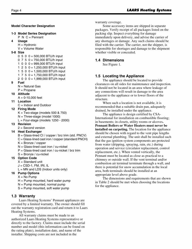
Model Character Designation
1-3 Model Series DesignationP N C = Pennant
4 UsageH = HydronicV = Volume Water
5-8 Size0 5 0 0 = 500,000 BTU/h input0 7 5 0 = 750,000 BTU/h input1 0 0 0 = 999,000 BTU/h input1 2 5 0 = 1,250,000 BTU/h input1 5 0 0 = 1,500,000 BTU/h input1 7 5 0 = 1,750,000 BTU/h input2 0 0 0 = 1,999,000 BTU/h input
9 FuelN = Natural GasP = Propane
10 AltitudeA = 0-10,000 feet
11 LocationC = Indoor and Outdoor
12 Firing ModeK = Two-stage (models 500 & 750)N = Three-stage (model 1000)L = Four-stage (models 1250 - 2000)
13 Revision2 = Second version
14 Heat ExchangerB = Glass-lined CI / copper / brz trim (std. PNCV)C = Glass-lined cast iron / copper (standard PNCH)K = Bronze / copperN = Glass-lined cast iron / cu-nickelP = Glass-lined cast iron / cu-nickel / brz trimS = Bronze / cu-nickel
15 Option CodeX = Standard unitJ = CSD-1, FM, IRI, ILL = MN and LDS (Indoor units only)
16 Pump OptionsX = No PumpH = Pump mounted, hard water pumpN = Pump mounted, normal pumpS = Pump mounted, soft water pump
1.3 WarrantyLaars Heating Systems’ Pennant appliances are
covered by a limited warranty. The owner should fillout the warranty registration card and return it to LaarsHeating Systems.
All warranty claims must be made to anauthorized Laars Heating Systems representative ordirectly to the factory. Claims must include the serialnumber and model (this information can be found onthe rating plate), installation date, and name of theinstaller. Shipping costs are not included in the
warranty coverage.Some accessory items are shipped in separate
packages. Verify receipt of all packages listed on thepacking slip. Inspect everything for damageimmediately upon delivery, and advise the carrier ofany shortages or damage. Any such claims should befiled with the carrier. The carrier, not the shipper, isresponsible for shortages and damage to the shipmentwhether visible or concealed.
1.4 DimensionsSee Figure 1.
1.5 Locating the ApplianceThe appliance should be located to provide
clearances on all sides for maintenance and inspection.It should not be located in an area where leakage ofany connections will result in damage to the areaadjacent to the appliance or to lower floors of thestructure.
When such a location is not available, it isrecommended that a suitable drain pan, adequatelydrained, be installed under the appliance.
The appliance is design certified by CSA-International for installation on combustible flooring;in basements; in closets, utility rooms or alcoves.Pennant Boilers or Water Heaters must never beinstalled on carpeting. The location for the applianceshould be chosen with regard to the vent pipe lengthsand external plumbing. The unit shall be installed suchthat the gas ignition system components are protectedfrom water (dripping, spraying, rain, etc.) duringoperation and service (circulator replacement, controlreplacement, etc.). When vented vertically, thePennant must be located as close as practical to achimney or outside wall. If the vent terminal and/orcombustion air terminal terminate through a wall, andthere is potential for snow accumulation in the localarea, both terminals should be installed at anappropriate level above grade.
The dimensions and requirements that are shownin Table 2 should be met when choosing the locationsfor the appliance.

Pennant Page 5
Figure 1. Dimensional Data.
Shipping WeightSize lbs. kg500 425 193750 505 2291000 615 2791250 675 3061500 760 3451750 825 3752000 955 434
*Add 55 lbs. (25kg) for pump-mounted units.
Air Vent Horiz.A B C D E F G H Conn. Conn. Vent
Size in cm in cm in cm in cm in cm in cm in cm in cm W V Pipe500 33½ 85 15¾ 40 5¾ 15 29¾ 76 32¾ 83 7¾ 20 8¾ 22 46 117 6 15 6 15 6 15750 45½ 116 21¾ 55 5¾ 15 29¾ 76 32¾ 83 7¾ 20 8¾ 22 58 147 6 15 8 20 6 151000 57½ 146 28¾ 73 5¾ 15 29¾ 76 32¾ 83 7¾ 20 7 18 70 178 8 20 10 25 8 201250 68 172 34 86 101/8 26 30¾ 78 29½ 75 8¾ 22 8¾ 22 80 203 8 20 12 30 8 201500 78½ 199 39¾ 101 101/8 26 30¾ 78 29½ 75 8¾ 22 8¾ 22 91 231 8 20 12 30 8 201750 89 226 44½ 113 101/8 26 30¾ 78 29½ 75 8¾ 22 8¾ 22 101 256 8 20 14 36 8 202000 99½ 253 49¾ 126 101/8 26 30¾ 78 29½ 75 8¾ 22 8¾ 22 112 284 12 30 14 36 12 30
*Air and vent connections may be on top or back of the Pennant, and are field convertible. Dimensions in inches cm.

LAARS Heating SystemsPage 6
Required RecommendedAppliance Clearance From Service AccessSurface Combustible Material Clearance
inches cm inches cm
Left Side 1 2.5 24 61
Right Side 1 2.5 24 61
Top 1 2.5 12 30
Back 1 2.5 **12** 30**
Front 1 2.5 36 91
Vertical(Category 1) 6* 15.2*
Vent
Horizontal per UL1738 venting(Category 3) system supplier’s
Vent instructions
*1" (2.5cm) when b-vent is used.**When vent and/or combustion air connects to the back,recommended clearance is 36" (91cm).
Table 2. Clearances.
1.6 Locating Pump-Mounted Water Heaterwith Respect to Storage Tank(s)For best results, a pump-mounted Pennant water
heater should be located within 15 feet (4.6m) of thestorage tank(s). The pump is sized for 30 feet (9.1m)of piping.
If the appliance must be installed with longerpiping runs, then larger diameter pipe or tubing shallbe used. Consult the factory for assistance.
1.7 Locating Pump-Mounted Boiler withRespect to Return/Supply HeaderFor the best results, a pump-mounted Pennant
Boiler should be located within 15 feet (4.6m) of thesupply and return headers. The pump is sized for 30feet (9.1m) of piping.
If the appliance must be installed with longerpiping runs, then larger diameter tubing shall be used.Consult the factory for assistance.
1.8 Locating Appliance for CorrectHorizontal Vent/Ducted Air DistanceFrom Outside WallThe forced draft combustion air blower/blowers
in the appliance has/have sufficient power to pull airand vent properly when the following guidelines forhorizontal air and vent are followed (see Table 1).NOTE: On models 750-2000, the vent collar size islarger than the size of the vent pipe that can be used.Vent collar size and horizontal pipe diameters can befound in Table 1. The larger vent collar size is toaccommodate Category I (vertical) vent systems.
NOTE: When located on the same wall, the Pennantcombustion air intake terminal must be installed aminimum of 12" (30cm) below the exhaust ventterminal and separated by a minimum of 36 inches(91cm) horizontally.
The air intake terminal must be installed highenough to avoid blockage from snow, leaves and otherdebris.
SECTION 2.Venting and Combustion Air2.1 Combustion Air
Pennant boilers and water heaters must haveprovisions for combustion and ventilation air inaccordance with section 5.3, Air for Combustion andVentilation, of the National Fuel Gas Code, ANSIZ223.1, or Sections 7.2, 7.3 or 7.4 of CSA B149.1,Installation Codes, or applicable provisions of thelocal building codes.
A Pennant appliance may receive combustion airfrom the space in which it is installed, or it can beducted directly to the unit from the outside.Ventilation air must be provided in either case.
2.1.1 Combustion Air From RoomIn the United States, the most common
requirements specify that the space shall communicatewith the outdoors in accordance with method 1 or 2,which follow. Where ducts are used, they shall be ofthe same cross-sectional area as the free area of theopenings to which they connect.
Horizontal Air CollarHeater Vent Collar Vent Pipe & Pipe Max. Pipe Max. No. Side Wall Side WallSize Size Diameter Diameter Length of Elbows Vent Combustion
Terminal Air Terminal
in. cm in. cm in cm ft. m Part Number Part Number
500 6 15 6 15 6 15 50 15 3 CA001401 20260701
750 8 20 6 15 6 15 50 15 3 CA001401 20260701
1000 10 25 8 20 8 20 50 15 3 CA001402 20260703
1250 12 30 8 20 8 20 50 15 3 CA001403 20260703
1500 12 30 8 20 8 20 50 15 3 CA001403 20260703
1750 14 36 8 20 8 20 50 15 3 CA001403 20260703
2000 14 36 12 30 12 30 50 15 3 CA001404 20260706
Table 1. Horizontal Vent / Combustion Air Parameters.
Pennant Page 7
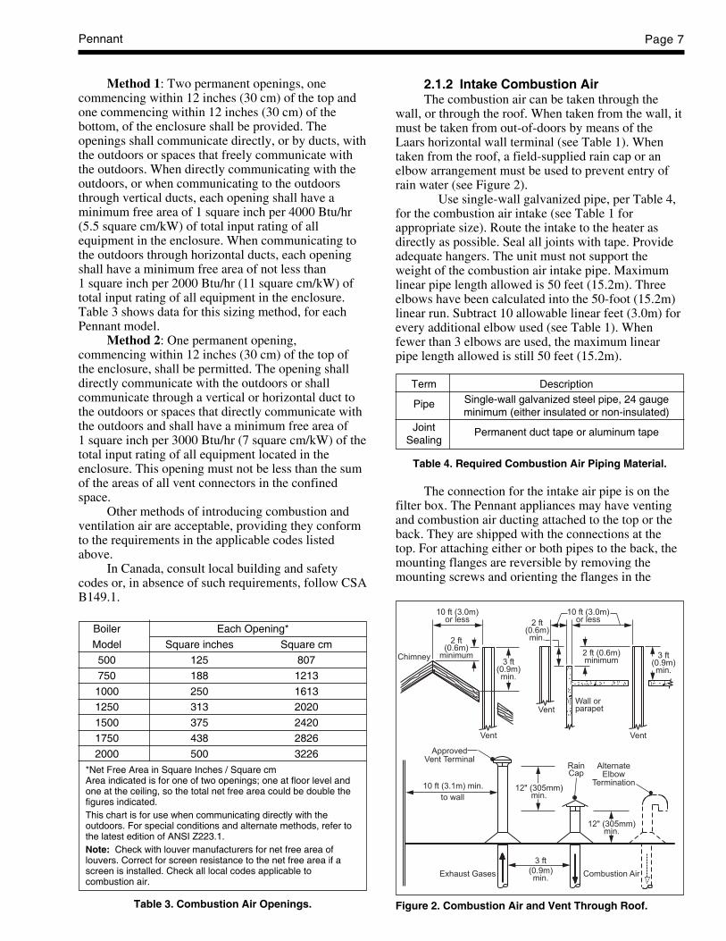
Method 1: Two permanent openings, onecommencing within 12 inches (30 cm) of the top andone commencing within 12 inches (30 cm) of thebottom, of the enclosure shall be provided. Theopenings shall communicate directly, or by ducts, withthe outdoors or spaces that freely communicate withthe outdoors. When directly communicating with theoutdoors, or when communicating to the outdoorsthrough vertical ducts, each opening shall have aminimum free area of 1 square inch per 4000 Btu/hr(5.5 square cm/kW) of total input rating of allequipment in the enclosure. When communicating tothe outdoors through horizontal ducts, each openingshall have a minimum free area of not less than1 square inch per 2000 Btu/hr (11 square cm/kW) oftotal input rating of all equipment in the enclosure.Table 3 shows data for this sizing method, for eachPennant model.
Method 2: One permanent opening,commencing within 12 inches (30 cm) of the top ofthe enclosure, shall be permitted. The opening shalldirectly communicate with the outdoors or shallcommunicate through a vertical or horizontal duct tothe outdoors or spaces that directly communicate withthe outdoors and shall have a minimum free area of1 square inch per 3000 Btu/hr (7 square cm/kW) of thetotal input rating of all equipment located in theenclosure. This opening must not be less than the sumof the areas of all vent connectors in the confinedspace.
Other methods of introducing combustion andventilation air are acceptable, providing they conformto the requirements in the applicable codes listedabove.
In Canada, consult local building and safetycodes or, in absence of such requirements, follow CSAB149.1.
Boiler Each Opening*
Model Square inches Square cm
500 125 807
750 188 1213
1000 250 1613
1250 313 2020
1500 375 2420
1750 438 2826
2000 500 3226
*Net Free Area in Square Inches / Square cmArea indicated is for one of two openings; one at floor level andone at the ceiling, so the total net free area could be double thefigures indicated.This chart is for use when communicating directly with theoutdoors. For special conditions and alternate methods, refer tothe latest edition of ANSI Z223.1.Note: Check with louver manufacturers for net free area oflouvers. Correct for screen resistance to the net free area if ascreen is installed. Check all local codes applicable tocombustion air.
Table 3. Combustion Air Openings.
2.1.2 Intake Combustion AirThe combustion air can be taken through the
wall, or through the roof. When taken from the wall, itmust be taken from out-of-doors by means of theLaars horizontal wall terminal (see Table 1). Whentaken from the roof, a field-supplied rain cap or anelbow arrangement must be used to prevent entry ofrain water (see Figure 2).
Use single-wall galvanized pipe, per Table 4,for the combustion air intake (see Table 1 forappropriate size). Route the intake to the heater asdirectly as possible. Seal all joints with tape. Provideadequate hangers. The unit must not support theweight of the combustion air intake pipe. Maximumlinear pipe length allowed is 50 feet (15.2m). Threeelbows have been calculated into the 50-foot (15.2m)linear run. Subtract 10 allowable linear feet (3.0m) forevery additional elbow used (see Table 1). Whenfewer than 3 elbows are used, the maximum linearpipe length allowed is still 50 feet (15.2m).
Term Description
Pipe Single-wall galvanized steel pipe, 24 gaugeminimum (either insulated or non-insulated)
Joint Permanent duct tape or aluminum tapeSealing
Table 4. Required Combustion Air Piping Material.
The connection for the intake air pipe is on thefilter box. The Pennant appliances may have ventingand combustion air ducting attached to the top or theback. They are shipped with the connections at thetop. For attaching either or both pipes to the back, themounting flanges are reversible by removing themounting screws and orienting the flanges in the
Figure 2. Combustion Air and Vent Through Roof.

LAARS Heating SystemsPage 8
desired position. Replace the screws after positioningflanges. Run a bead of silicone around the collar andslide the pipe over the collar. Secure with sheet metalscrews.
In addition to air needed for combustion, air shallalso be supplied for ventilation, including all airrequired for comfort and proper working conditionsfor personnel. The Pennant loses less than 1 percent ofits input rating to the room, but other heat sources maybe present.
2.2 Venting2.2.1 Vent CategoriesDepending upon desired Pennant venting, it may
be considered a Category I or a Category IIIappliance. In general, a vertical vent system will be aCategory I system. However, in rare instances, aPennant’s vertical vent system may be consideredCategory III. In the U.S., the National Fuel Gas Code(ANSI Z223.1-Latest Edition), or in Canada the CSAB149.1 (latest edition), defines a Category I ventsystem, and includes rules and tables to size these ventsystems. If the Pennant’s vertical vent system does notsatisfy the criteria for Category I venting, it must bevented as a Category III system.
All Pennant vent systems which dischargehorizontally (without the use of a power venter) areconsidered Category III vent systems.
2.2.2 Category I VentWhen vented as a category I appliance, the vent
system must conform to the National Fuel Gas Code(ANSI Z223.1-Latest Edition) in the U.S., or inCanada, to CSA B149.1 (latest edition). The ventsystem must be sized and installed for a Category IFan-Assisted Appliance.
If chimney height is greater than 25 feet, or ifmultiple units are vented into the same vertical vent, abarometric damper must be installed on eachappliance, such that the flue draft does not exceed(negative) 0.1" w.c.
If using a power venter for any type of CategoryI venting, the draft should be set between (negative)0.01 and 0.10" w.c.
2.2.3 Common Venting SystemsPennant units are Category I fan-assisted when
vented vertically and adhering to all applicable codes.Pennant units are not allowed to be vented into acommon horizontal vent system, unless a properlysized vent fan is used, and the common vent system isproperly designed by the vent fan manufacturer or aqualified engineer. When common venting Pennantfan-assisted unit with other appliances through oneshared vertical duct called a “common vent”, specialcare must be taken by the installer to ensure safeoperation. In the event that the common vent isblocked, it is possible, especially for fan-assisted
devices, to vent backwards through non-operatingappliances sharing the vent, allowing combustionproducts to infiltrate occupied spaces. If theappliances are allowed to operate in this condition,serious injury or death may occur.
WARNINGOperation of appliances with a blocked commonvent may lead to serious injury or death. Safetydevices must be implemented to prevent blockedcommon vent operation. If safe operation of allappliances connected to a common vent cannot beassured, including prevention of spillage of fluegasses into living spaces, common venting shouldnot be applied, and appliances should each bevented separately.
It is for this reason that, in addition to followingproper vent sizing, construction and safetyrequirements from the National Fuel Gas Code, ANSIZ223.1 or in Canada, from CSA B149.1 as well as allapplicable local codes, it is required that installersprovide some means to prevent operation with ablocked common vent. It is suggested that a blockedvent safety system be employed such that if the switchfrom one appliance trips due to excessive stack spill orbackpressure indicating a blocked vent condition, thatall appliances attached to the vent be locked out andprevented from operating. Note that the Pennant isequipped with a blocked vent safety (pressure) switch,as shipped. However, this safety switch has only beendesigned and tested to be effective in installationswhere the Pennant is vented separately and NOTcommon vented with other appliances. As anadditional precaution, it is recommended that a CarbonMonoxide (CO) alarm be installed in all enclosedspaces containing combustion appliances. If assistanceis required in determining how a blocked vent safetysystem should be connected to a LAARS product,please call Applications Engineering at the Rochesterphone number listed on back cover of this manual.
Refer to the installation and operatinginstructions on all appliances to be common vented forinstructions, warnings, restrictions and safetyrequirements. If safe operation of all appliancesconnected to a common vent cannot be assured,including prevention of spillage of flue gasses intoliving spaces, common venting should not be applied,and appliances should each be vented separately.
2.2.4 Category III VentWhen the Pennant is vented with horizontal
discharge, it must be installed per this installationmanual and the venting system manufacturer’sinstallation instructions. The vent system must besealed stainless steel, per Table 5.
Route the vent pipe to the heater as directly aspossible. Seal all joints and provide adequate hangers
Pennant Page 9
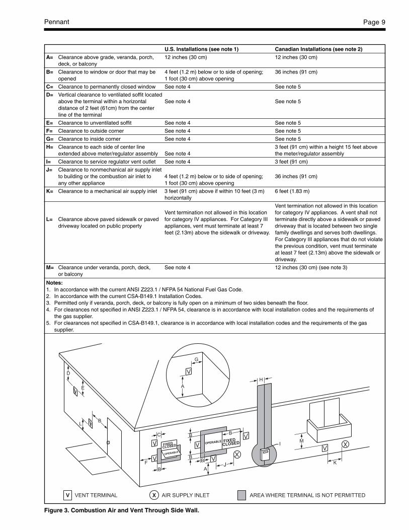
U.S. Installations (see note 1) Canadian Installations (see note 2)
A= Clearance above grade, veranda, porch, 12 inches (30 cm) 12 inches (30 cm)deck, or balcony
B= Clearance to window or door that may be 4 feet (1.2 m) below or to side of opening; 36 inches (91 cm)opened 1 foot (30 cm) above opening
C= Clearance to permanently closed window See note 4 See note 5
D= Vertical clearance to ventilated soffit locatedabove the terminal within a horizontal See note 4 See note 5distance of 2 feet (61cm) from the centerline of the terminal
E= Clearance to unventilated soffit See note 4 See note 5
F= Clearance to outside corner See note 4 See note 5
G= Clearance to inside corner See note 4 See note 5
H= Clearance to each side of center line 3 feet (91 cm) within a height 15 feet aboveextended above meter/regulator assembly See note 4 the meter/regulator assembly
I= Clearance to service regulator vent outlet See note 4 3 feet (91 cm)
J= Clearance to nonmechanical air supply inletto building or the combustion air inlet to 4 feet (1.2 m) below or to side of opening; 36 inches (91 cm)any other appliance 1 foot (30 cm) above opening
K= Clearance to a mechanical air supply inlet 3 feet (91 cm) above if within 10 feet (3 m) 6 feet (1.83 m)horizontally
Vent termination not allowed in this locationVent termination not allowed in this location for category IV appliances. A vent shall not
L= Clearance above paved sidewalk or paved for category IV appliances. For Category III terminate directly above a sidewalk or paveddriveway located on public property appliances, vent must terminate at least 7 driveway that is located between two single
feet (2.13m) above the sidewalk or driveway. family dwellings and serves both dwellings.For Category III appliances that do not violatethe previous condition, vent must terminateat least 7 feet (2.13m) above the sidewalk ordriveway.
M= Clearance under veranda, porch, deck, See note 4 12 inches (30 cm) (see note 3)or balcony
Notes:1. In accordance with the current ANSI Z223.1 / NFPA 54 National Fuel Gas Code.2. In accordance with the current CSA-B149.1 Installation Codes.3. Permitted only if veranda, porch, deck, or balcony is fully open on a minimum of two sides beneath the floor.4. For clearances not specified in ANSI Z223.1 / NFPA 54, clearance is in accordance with local installation codes and the requirements of
the gas supplier.5. For clearances not specified in CSA-B149.1, clearance is in accordance with local installation codes and the requirements of the gas
supplier.
Figure 3. Combustion Air and Vent Through Side Wall.

LAARS Heating SystemsPage 10
as required in the venting system manufacturer’sInstallation Instructions. Horizontal portions of theventing system must be supported to prevent saggingand may not have any low sections that could trapcondensate. The unit must not support the weight ofthe vent pipe. Horizontal runs must slope downwardsnot less than ¼ inch per foot (2 cm/m) from the unit tothe vent terminal. Reference Table 1 for the size of theCategory III vent system. Up to three elbows can beused with 50 linear feet (15.2m) of pipe. Subtract 10allowable linear feet (3.0m) for every additional elbowused.
Term DescriptionPipe Must comply with UL Standard 1738
such as Type 29-4C Stainless Steel(either insulated or non-insulated).
Joint Follow vent manufacturer’s instructions Sealing
Table 5. Required Horizontal Venting Material.
WARNINGThe outdoor vent terminal gets hot. Unit must beinstalled in such a way as to reduce the risk ofburns from contact with the vent terminal.
2.3 Locating Vent & Combustion AirTerminals2.3.1 Side Wall Vent TerminalThe appropriate Laars side wall vent hood must
be used, and is listed in the installation and operationmanual. The terminal provides a means of installingthe vent piping through the building wall, and must belocated in accordance with ANSI Z223.1/NFPA 54and applicable local codes. In Canada, the installationmust be in accordance with CSA B149.1 or .2 andlocal applicable codes. Consider the following wheninstalling the terminal:1. Figure 3 shows the requirements for mechanical
vent terminal clearances for the U.S. and Canada.2. Vent terminals for condensing appliances or
appliances with condensing vents are notpermitted to terminate above a public walkway,or over an area where condensate or vapor couldcreate a nuisance or hazard.
3. Locate the vent terminal so that vent gasescannot be drawn into air conditioning systeminlets.
4. Locate the vent terminal so that vent gasescannot enter the building through doors,windows, gravity inlets or other openings.Whenever possible, locations under windows ornear doors should be avoided.
5. Locate the vent terminal so that it cannot beblocked by snow. The installer may determinethat a vent terminal must be higher than theminimum shown in codes, depending upon localconditions.
6. Locate the terminal so the vent exhaust does notsettle on building surfaces or other nearbyobjects. Vent products may damage suchsurfaces or objects.
7. If the boiler or water heater uses ductedcombustion air from an intake terminal locatedon the same wall, locate the vent terminal at least3 feet (0.9m) horizontally from the combustionair terminal, and locate the vent terminal at least1 foot (0.3m) above the combustion air terminal.
2.3.2 Side Wall Combustion Air TerminalThe Laars side wall combustion air terminal
(listed in Table 1) must be used when the unit takes itscombustion air through a duct from a side wall.Consider the following when installing the terminal:1. Do not locate the air inlet terminal near a source
of corrosive chemical fumes (e.g., cleaning fluid,chlorinated compounds, etc.)
2. Locate the terminal so that it will not be subjectto damage by accident or vandalism.
3. Locate the combustion air terminal so that itcannot be blocked by snow. The National FuelGas Code requires that it be at least 12 inches(30 cm) above grade, but the installer maydetermine it should be higher, depending uponlocal conditions.
4. If the Pennant is side-wall vented to the samewall, locate the vent terminal at least 3 feet(0.9m) horizontally from the combustion airterminal, and locate the vent terminal at least 1foot (0.3m) above the combustion air terminal(see Figure 3).
2.3.3 Vertical Vent TerminalWhen the unit is vented through the roof, the
vent must extend at least 3 feet (0.9m) above the pointat which it penetrates the roof. It must extend at least 2feet (0.6m) higher than any portion of a buildingwithin a horizontal distance of 10 feet (3.0m), andhigh enough above the roof line to prevent blockagefrom snow. When the combustion air is taken from theroof, the combustion air must terminate at least 12"(30cm) below the vent terminal (see Figure 2).
2.3.4 Vertical Combustion Air TerminalWhen combustion air is taken from the roof, a
field-supplied rain cap or an elbow arrangement mustbe used to prevent entry of rain water (see Figure 2).The opening on the end of the terminal must be atleast 12" (30cm) above the point at which it penetratesthe roof, and high enough above the roof line toprevent blockage from snow. When the ventterminates on the roof, the combustion air mustterminate at least 12" (30cm) below the vent terminal.

Pennant Page 11
2.4 Common Vent Test — BoilersWhen an existing boiler is removed from a
common venting system, the common venting systemis likely to be too large for proper venting of theappliances remaining connected to it.
At the time of removal of an existing boiler, thefollowing steps shall be followed with each applianceremaining connected to the common venting systemplaced in operation, while the other appliancesremaining connected to the common venting systemare not in operation.1. Seal any unused openings in the common
venting system.2. Visually inspect the venting system for proper
size and horizontal pitch and determine there isno blockage or restriction, leakage, corrosion andother deficiencies which could cause an unsafecondition.
3. Insofar as it is practical, close all building doorsand windows and all doors between the space inwhich the appliances remaining connected to thecommon venting system are located and otherspaces of the building. Turn on clothes dryersand any appliance not connected to the commonventing system. Turn on any exhaust fans, suchas range hoods and bathroom exhausts, so theywill operate at maximum speed. Do not operate asummer exhaust fan. Close fireplace dampers.
4. Place in operation the appliance being inspected.Follow the lighting instructions. Adjustthermostat so appliance will operatecontinuously.
5. Test for spillage at the draft hood relief openingafter 5 minutes of main burner operation. Use theflame of a match or candle, or smoke from acigarette, cigar or pipe.
6. After it has been determined that each applianceremaining connected to the common ventingsystem properly vents when tested as outlinedabove, return doors, windows, exhaust fans,fireplace dampers and any other gas burningappliance to their previous conditions of use.
7. Any improper operation of the common ventingsystem should be corrected so that theinstallation conforms to the National Fuel GasCode, ANSI Z223.1/NFPA 54 and/or CSAB149.1, Installation Codes. When resizing anyportion of the common venting system, thecommon venting system should be resized toapproach the minimum size as determined usingthe appropriate tables in Part II of the NationalFuel Gas Code, ANSI Z223.1/NFPA 54 and/orCSA B149.1, Installation Codes.
2.5 Vent Terminals for Outdoor UnitsFor outdoor applications, the vent and
combustion air openings must be covered with properterminals to prevent rain, snow and other objects from
falling into the Pennant.If local codes allow, outdoor installations may
use 1' of appropriately sized galvanized single wall orB-Vent and a rain cap for exhaust vent termination inthe default configuration (venting out of the top). Anappropriately sized galvanized 90° ell, positioned withthe opening facing down, may be used on thecombustion air inlet in the default configuration on theback of the unit. Note that some local codes mayrequire a higher vertical vent height, extending aboveany perimeter fencing, etc. In installations where theappearance of the vent is objectionable, the low profilevent terminals in Table 6 may be used.
Part numbers for the low profile terminals tocover the vent and combustion air openings are shownin Table 6.
Outdoor Vent OutdoorModel (Size) Terminal Combustion
Air Terminal
500 20254701 D2007900
750 20254703 D2007900
1000 20254705 D2008000
1250 D2007700 D2008000
1500 D2007700 D2008000
1750 D2007800 D2008000
2000 D2007800 D2008200
Table 6. Vent Terminals for Outdoor Units.
SECTION 3.Gas Supply and Piping
3.1 Gas Supply and PipingGas piping should be supported by suitable
hangers or floor stands, not by the appliance.The Pennant’s gas train allows the user to pipe
the gas from either the right side or the left side of theunit. As shipped, the right side of the gas train iscapped off, and there is a manual valve on the leftside. If desired, the manual valve on the left side of thegas train may be moved to the right side, and the capon the right side may be moved to the left.
Review the following instructions beforeproceeding with the installation.1. Verify that the appliance is fitted for the proper
type of gas by checking the rating plate. Pennantappliances are equipped to operate at elevationsup to 10000 feet (3050m). Pennant appliancesmay be adjusted to operate properly at altitudesabove 2500 feet (see Section 6.5.2) and the inputwill be reduced if the heating value of the gassupply is below sea level values.
2. The maximum inlet gas pressure must not exceed13" W.C (3.2kPa). The minimum inlet gaspressure is 5" W.C. (1.2kPa).

LAARS Heating SystemsPage 12
3. Refer to Table 7, size supply.4. Run gas supply line in accordance with all
applicable codes.5. Locate and install manual shutoff valves in
accordance with state and local requirements.6. A sediment trap must be provided upstream of
the gas controls.7. All threaded joints should be coated with piping
compound resistant to action of liquefiedpetroleum gas.
8. The appliance and its individual shutoff valvemust be disconnected from the gas supply pipingduring any pressure testing of that system at testpressures in excess of 1/2 PSIG (3.45kpa).
9. The unit must be isolated from the gas supplysystem by closing its individual manual shutoffvalve during any pressure testing of the gassupply piping system at test pressures equal to orless than 1/2 PSIG (3.45kpa).
10. The appliance and its gas connection must beleak tested before placing it in operation.
11. Purge all air from gas lines.
WarningDo not use open flame to check for leaks. An openflame could lead to explosion, which could result inproperty damage, serious injury or death.
NOTE: The Pennant appliance and all other gasappliances sharing the gas supply line must be firingat maximum capacity to properly measure the inletsupply pressure. The pressure can be measured atthe supply pressure port on the gas valve. Low gas
pressure could be an indication of an undersized gasmeter, undersized gas supply lines and/or anobstructed gas supply line.
SECTION 4A.Water Connections —Pennant Boiler
4A.1 Heating System Piping:Hot Supply Connections — Boiler
NOTE: This appliance must be installed in a closedpressure system with a minimum of 12 psi (82.7kPa)static pressure at the boiler.
Hot water piping should be supported by suitablehangers or floor stands. Do not support piping withthis appliance. Due to expansion and contraction ofcopper pipe, consideration should be given to the typeof hangers used. Rigid hangers may transmit noisethrough the system resulting from the piping sliding inthe hangers. It is recommended that padding be usedwhen rigid hangers are installed. Maintain 1"clearance to combustibles for hot water pipes.
Pipe the discharge of the relief valve (full size) toa drain or in a manner to prevent injury in the event ofpressure relief. Install an air purger, an air vent, adiaphragm-type expansion tank, and a hydronic flowcheck in the system supply loop. Minimum fillpressure must be 12psig (82.7kPa). Install shutoffvalves where required by code.
Distance from Gas Meteror Last Stage Regulator
Model andGas Type 0-100' 0-31m 100-200' 31-61m 200-300' 61-91m
500 natural 1-1/2" 3.8cm 2" 5.1cm 2" 5.1cm500 propane 1" 2.5cm 1-1/2" 3.8cm 1-1/2" 3.8cm750 natural 2" 5.1cm 2" 5.1cm 2-1/2" 6.4cm750 propane 1-1/2" 3.8cm 1-1/2" 3.8cm 2" 5.1cm1000 natural 2" 5.1cm 2-1/2" 6.4cm 3" 7.6cm1000 propane 1-1/2" 3.8cm 2" 5.1cm 2-1/2" 6.4cm1250 natural 2-1/2" 6.4cm 2-1/2" 6.4cm 3" 7.6cm1250 propane 2" 5.1cm 2" 5.1cm 2-1/2" 6.4cm
1500 natural 2-1/2" 6.4cm 3" 7.6cm 3" 7.6cm1500 propane 2" 5.1cm 2-1/2" 6.4cm 2-1/2" 6.4cm1750 natural 2-1/2" 6.4cm 3" 7.6cm 3" 7.6cm1750 propane 2" 5.1cm 2-1/2" 6.4cm 2-1/2" 6.4cm2000 natural 3" 7.6cm 3" 7.6cm 3-1/2" 8.9cm2000 propane 2-1/2" 6.4cm 2-1/2" 6.4cm 3" 7.6cm
Notes:1.These figures are based on 1/2" (0.12kPa) water column pressure drop.2.Check supply pressure and local code requirements before proceeding with work.3.Pipe fittings must be considered when determining gas pipe sizing.
Table 7. Gas Piping Size.
Pennant Page 13
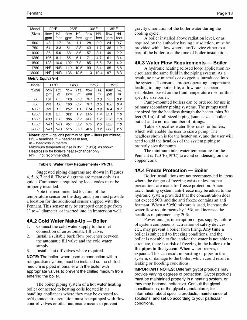
Suggested piping diagrams are shown in Figures4, 5, 6, 7 and 8. These diagrams are meant only as aguide. Components required by local codes must beproperly installed.
Note the recommended location of thetemperature sensor on the diagrams; you must providea location for the additional sensor shipped with thePennant. This sensor may be strapped onto pipe from1" to 4" diameter, or inserted into an immersion well.
4A.2 Cold Water Make-Up — Boiler1. Connect the cold water supply to the inlet
connection of an automatic fill valve.2. Install a suitable back flow preventer between
the automatic fill valve and the cold watersupply.
3. Install shut off valves where required.NOTE: The boiler, when used in connection with arefrigeration system, must be installed so the chilledmedium is piped in parallel with the boiler withappropriate valves to prevent the chilled medium fromentering the boiler.
The boiler piping system of a hot water heatingboiler connected to heating coils located in airhandling appliances where they may be exposed torefrigerated air circulation must be equipped with flowcontrol valves or other automatic means to prevent
gravity circulation of the boiler water during thecooling cycle.
A boiler installed above radiation level, or asrequired by the authority having jurisdiction, must beprovided with a low water cutoff device either as apart of the boiler or at the time of boiler installation.
4A.3 Water Flow Requirements — BoilerA hydronic heating (closed loop) application re-
circulates the same fluid in the piping system. As aresult, no new minerals or oxygen is introduced intothe system. To ensure a proper operating temperatureleading to long boiler life, a flow rate has beenestablished based on the fluid temperature rise for thisspecific size boiler.
Pump-mounted boilers can be ordered for use inprimary secondary piping systems. The pumps usedare sized for the headloss through the heater, plus 30feet (9.1m) of full-sized piping (same size as boileroutlet) and a normal number of fittings.
Table 8 specifies water flow rates for boilers,which will enable the user to size a pump. Theheadloss shown is for the heater only, and the user willneed to add the headloss of the system piping toproperly size the pump.
The minimum inlet water temperature for thePennant is 120°F (49°C) to avoid condensing on thecopper coils.
4A.4 Freeze Protection — BoilerBoiler installations are not recommended in areas
where the danger of freezing exists unless properprecautions are made for freeze protection. A nontoxic, heating system, anti-freeze may be added to thehydronic system provided that the concentration doesnot exceed 50% and the anti freeze contains an antifoamant. When a 50/50 mixture is used, increase thewater flow requirements by 15%, and increase theheadloss requirements by 20%.
Power outage, interruption of gas supply, failureof system components, activation of safety devices,etc., may prevent a boiler from firing. Any time aboiler is subjected to freezing conditions, and theboiler is not able to fire, and/or the water is not able tocirculate, there is a risk of freezing in the boiler or inthe pipes in the system. When water freezes, itexpands. This can result in bursting of pipes in thesystem, or damage to the boiler, which could result inleaking or flooding conditions.IMPORTANT NOTES: Different glycol products mayprovide varying degrees of protection. Glycol productsmust be maintained properly in a heating system, orthey may become ineffective. Consult the glycolspecifications, or the glycol manufacturer, forinformation about specific products, maintenance ofsolutions, and set up according to your particularconditions.
Model 20°F 25°F 30°F 35°F(Size) flow H/L flow H/L flow H/L flow H/L
gpm feet gpm feet gpm feet gpm feet500 43 1.7 34 1.1 28 0.9 24 0.7750 64 3.3 51 2.3 43 1.7 36 1.21000 85 5.0 68 3.6 57 3.1 49 2.21250 106 8.1 85 6.1 71 4.7 61 3.41500 128 10.0 102 7.2 85 5.5 73 4.21750 N/R N/R 119 10.5 99 8.4 85 5.82000 N/R N/R 136 12.5 113 10.4 97 8.3
Metric Equivalent
Model 11°C 14°C 17°C 19°C(Size) flow H/L flow H/L flow H/L flow H/L
lpm m lpm m lpm m lpm m500 161 0.5 129 0.3 107 0.3 92 0.2750 241 1.0 193 0.7 161 0.5 138 0.41000 321 1.5 257 1.1 214 0.9 184 0.71250 401 2.5 322 1.9 269 1.4 231 1.01500 483 3.0 386 2.2 322 1.7 276 1.31750 N/R N/R 451 3.2 375 2.6 322 1.82000 N/R N/R 515 3.8 429 3.2 368 2.5
Notes: gpm = gallons per minute, lpm = liters per minute,H/L = headloss, ft = headloss in feet,m = headloss in meters.Maximum temperature rise is 35°F (19°C), as shown.Headloss is for boiler’s heat exchanger only.N/R = not recommended.
Table 8. Water Flow Requirements - PNCH.

LAARS Heating SystemsPage 14
SECTION 4B.Water Connections —Pennant Water Heater
4B.1 Water System Piping — Water HeaterHot water piping should be supported by suitable
hangers or floor stands. Do not support piping withthis appliance. Due to expansion and contraction ofcopper pipe, consideration should be given to the typeof hangers used. Rigid hangers may transmit noisethrough the system resulting from the piping sliding inthe hangers. It is recommended that padding be usedwhen rigid hangers are installed.
The Pennant can be used with several differenttypes of readily available storage tanks. A pump drawswater from the storage tank and pumps the waterthrough the heater and back into the tank. Pump-mounted units have a circulating pump built into thewater heater. The pumps used are sized for theheadloss through the heater, plus 30 feet (9.1m) offull-sized piping (same size as boiler outlet) and anormal number of fittings. Pumps used on pump-mounted unit are sized for soft/normal or hard water,so make sure a pump-mounted unit matches the waterquality of the installation.
Pipe the outlet from the heater’s relief valve suchthat any discharge from the relief valve will beconducted to a suitable place for disposal when reliefoccurs. Do not reduce line size or install any valves inthis line. The line must be installed to allow completedrainage of both the valve and the line.
Suggested piping diagrams are shown in Figures9, 10, 11 and 12. These diagrams are meant only as aguide. Components required by local codes must beproperly installed.
Note the recommended location of thetemperature sensor on the diagrams. The Pennant isshipped with an additional sensor that can be used formore full-featured domestic water heating control. Toget these features, you must provide a location for theadditional sensor. It can be strapped to a pipe from 1"to 4" diameter, or inserted into a tank immersion well.
The minimum inlet water temperature for thePennant is 120°F (49°C) to avoid condensing on thecopper coils.
4B.2 Hot Water Supply Piping — Water HeaterFollow the tank manufacturer’s guidelines for
completion of the hot water system connections.NOTE: A listed temperature and pressure reliefvalve listed as complying with the Standard forRelief Valves and Automatic Gas Shutoff Devicesfor Hot Water Supply Systems (ANSI Z21.22 / CSA
4.4) of suitable discharge capacity must beinstalled in the separate storage tank system.
If the Pennant water heater is installed in aclosed water supply system, such as one having abackflow preventer in the cold water supply line, therelief valve may discharge periodically, due to thermalexpansion. Means (such as a properly-sized expansiontank) shall be provided to control thermal expansion.Contact the water supplier or local plumbing inspectoron how to control this situation.
4B.3 Water Flow Requirements — Water HeaterIn a water heating application (an open system),
new water is constantly being introduced. With thenew water comes a fresh supply of minerals that canbe deposited on the unit’s heat exchanger. This iscommonly known as scaling. The amount of mineralswill depend upon the hardness of the water. Water canalso be aggressive, and can erode metals, includingcopper, if the water is moved too quickly. The waterflow requirements for the Pennant water heater arebased upon the hardness of the water. The water flowis kept high enough to prevent scaling, but low enoughto prevent tube erosion. For extremely soft or hardwater, cupro-nickel tubes are available. Contact aLaars Representative if you have questions orconcerns about water quality.
Pump-mounted water heaters can be orderedwith standard pumps for soft or normal water or withpumps for hard water. The pumps used are sized forthe headloss through the heater, plus 30 feet (9.1m) offull-sized piping (same size as heater outlet) and anormal number of fittings.
Table 9 specifies water flow rates for waterheaters, which will enable the user to size a pump. Theheadloss shown is for the heater only, and the user willneed to add the headloss of the piping system toproperly size the pump.
4B.4 Combined Water Heating (potable) and Space Heating — Water Heater
NOTE: These systems are not allowed in theCommonwealth of Massachusetts.
Piping and components connected to this waterheater for the space heating application shall besuitable for use with potable water.
Toxic chemicals, such as used for boilertreatment, shall not be introduced into the potablewater used for space heating.
This water heater when used to supply potablewater shall not be connected to any heating system orcomponent(s) previously used with a non-potablewater heating appliance.
When the system requires water for heating attemperatures higher than required for other uses,
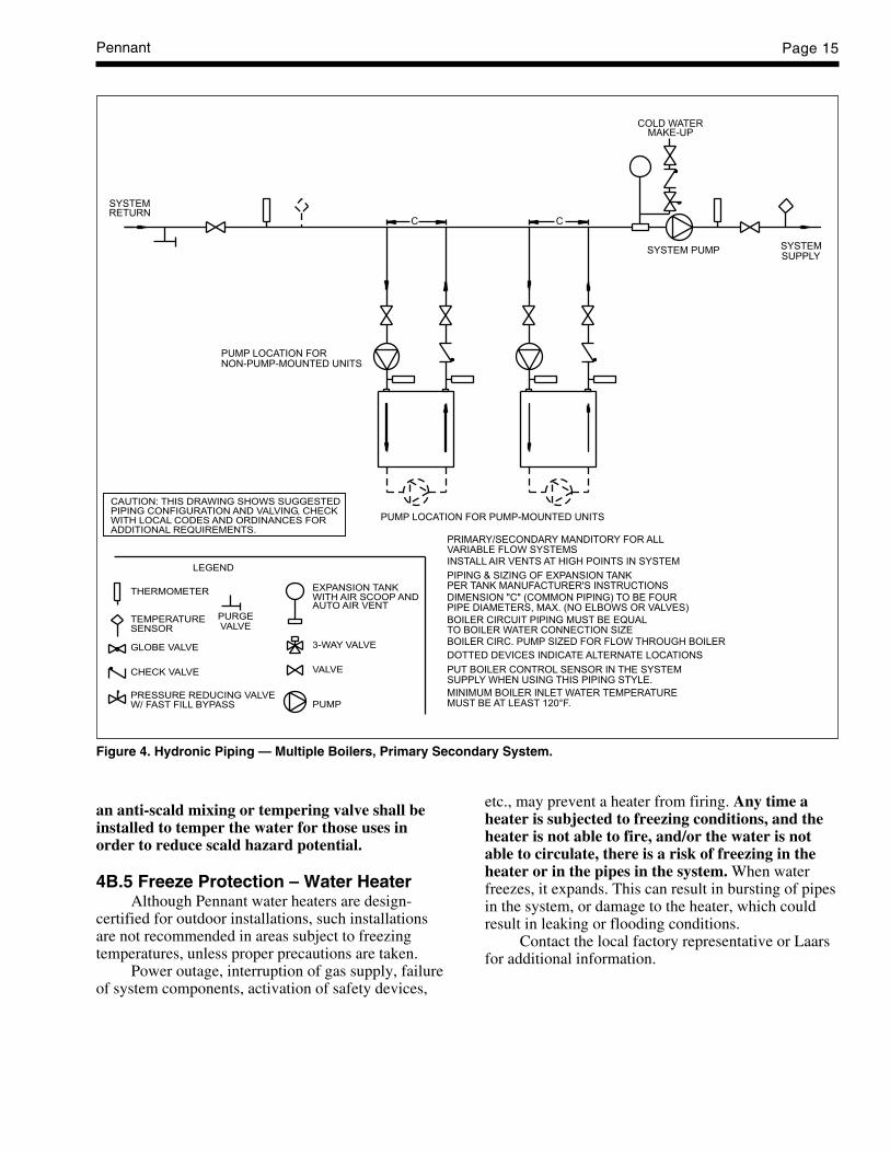
Pennant Page 15
PRIMARY/SECONDARY MANDITORY FOR ALLVARIABLE FLOW SYSTEMSINSTALL AIR VENTS AT HIGH POINTS IN SYSTEM
PIPING & SIZING OF EXPANSION TANKPER TANK MANUFACTURER'S INSTRUCTIONS
DIMENSION "C" (COMMON PIPING) TO BE FOURPIPE DIAMETERS, MAX. (NO ELBOWS OR VALVES)
BOILER CIRCUIT PIPING MUST BE EQUALTO BOILER WATER CONNECTION SIZEBOILER CIRC. PUMP SIZED FOR FLOW THROUGH BOILER
DOTTED DEVICES INDICATE ALTERNATE LOCATIONS
PUT BOILER CONTROL SENSOR IN THE SYSTEM
C
PUMP LOCATION FOR PUMP-MOUNTED UNITS
SYSTEM PUMP
MAKE-UPCOLD WATER
SUPPLYSYSTEM
PUMP LOCATION FORNON-PUMP-MOUNTED UNITS
RETURNSYSTEM
SUPPLY WHEN USING THIS PIPING STYLE.
MINIMUM BOILER INLET WATER TEMPERATUREMUST BE AT LEAST 120°F.
C
LEGEND
CHECK VALVE
THERMOMETER
TEMPERATURESENSOR
GLOBE VALVE
EXPANSION TANKWITH AIR SCOOP ANDAUTO AIR VENT
3-WAY VALVE
VALVE
CAUTION: THIS DRAWING SHOWS SUGGESTEDPIPING CONFIGURATION AND VALVING, CHECKWITH LOCAL CODES AND ORDINANCES FORADDITIONAL REQUIREMENTS.
PRESSURE REDUCING VALVEW/ FAST FILL BYPASS
PURGEVALVE
PUMP
Figure 4. Hydronic Piping — Multiple Boilers, Primary Secondary System.
an anti-scald mixing or tempering valve shall beinstalled to temper the water for those uses inorder to reduce scald hazard potential.
4B.5 Freeze Protection – Water HeaterAlthough Pennant water heaters are design-
certified for outdoor installations, such installationsare not recommended in areas subject to freezingtemperatures, unless proper precautions are taken.
Power outage, interruption of gas supply, failureof system components, activation of safety devices,
etc., may prevent a heater from firing. Any time aheater is subjected to freezing conditions, and theheater is not able to fire, and/or the water is notable to circulate, there is a risk of freezing in theheater or in the pipes in the system. When waterfreezes, it expands. This can result in bursting of pipesin the system, or damage to the heater, which couldresult in leaking or flooding conditions.
Contact the local factory representative or Laarsfor additional information.
LAARS Heating SystemsPage 16
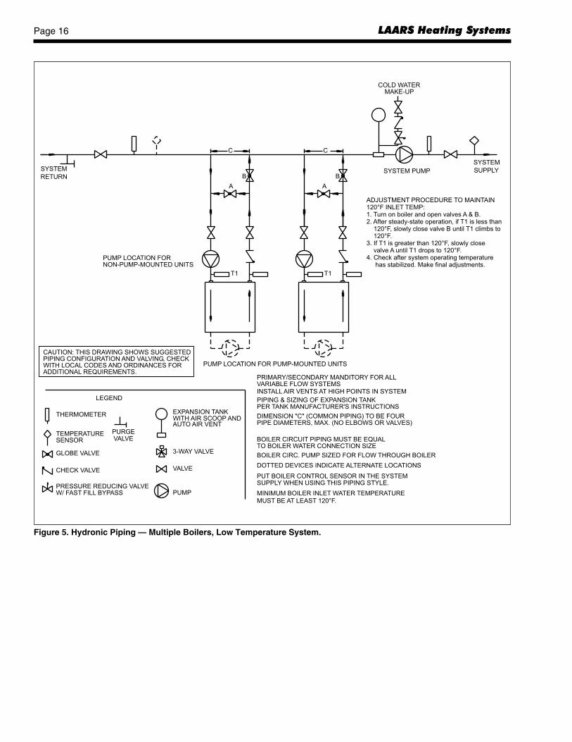
PRIMARY/SECONDARY MANDITORY FOR ALLVARIABLE FLOW SYSTEMSINSTALL AIR VENTS AT HIGH POINTS IN SYSTEM
PIPING & SIZING OF EXPANSION TANKPER TANK MANUFACTURER'S INSTRUCTIONS
DIMENSION "C" (COMMON PIPING) TO BE FOURPIPE DIAMETERS, MAX. (NO ELBOWS OR VALVES)
BOILER CIRCUIT PIPING MUST BE EQUALTO BOILER WATER CONNECTION SIZE
BOILER CIRC. PUMP SIZED FOR FLOW THROUGH BOILER
DOTTED DEVICES INDICATE ALTERNATE LOCATIONS
PUT BOILER CONTROL SENSOR IN THE SYSTEM
C
PUMP LOCATION FOR PUMP-MOUNTED UNITS
SYSTEM PUMP
MAKE-UPCOLD WATER
SUPPLY
SYSTEM
PUMP LOCATION FORNON-PUMP-MOUNTED UNITS
RETURN
SYSTEM
SUPPLY WHEN USING THIS PIPING STYLE.
MINIMUM BOILER INLET WATER TEMPERATUREMUST BE AT LEAST 120°F.
C
ADJUSTMENT PROCEDURE TO MAINTAIN120°F INLET TEMP:1. Turn on boiler and open valves A & B.2. After steady-state operation, if T1 is less than
slowly close valve B until T1 climbs to120°F.
3. If T1 is greater than 120°F, slowly closeuntil T1 drops to 120°F.
4. Check after system operating temperaturehas stabilized. Make final adjustments.
120°F,
valve A
A
B
T1
B
A
T1
LEGEND
CHECK VALVE
THERMOMETER
TEMPERATURESENSOR
GLOBE VALVE
EXPANSION TANKWITH AIR SCOOP ANDAUTO AIR VENT
3-WAY VALVE
VALVE
CAUTION: THIS DRAWING SHOWS SUGGESTEDPIPING CONFIGURATION AND VALVING, CHECKWITH LOCAL CODES AND ORDINANCES FORADDITIONAL REQUIREMENTS.
PRESSURE REDUCING VALVEW/ FAST FILL BYPASS
PURGEVALVE
PUMP
Figure 5. Hydronic Piping — Multiple Boilers, Low Temperature System.
Pennant Page 17
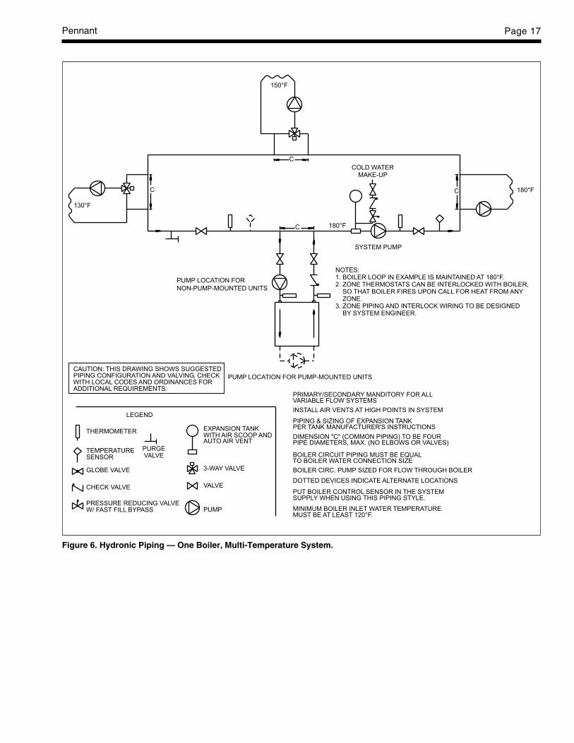
Figure 6. Hydronic Piping — One Boiler, Multi-Temperature System.
PRIMARY/SECONDARY MANDITORY FOR ALLVARIABLE FLOW SYSTEMS
INSTALL AIR VENTS AT HIGH POINTS IN SYSTEM
PIPING & SIZING OF EXPANSION TANKPER TANK MANUFACTURER'S INSTRUCTIONS
DIMENSION "C" (COMMON PIPING) TO BE FOURPIPE DIAMETERS, MAX. (NO ELBOWS OR VALVES)
BOILER CIRCUIT PIPING MUST BE EQUALTO BOILER WATER CONNECTION SIZE
BOILER CIRC. PUMP SIZED FOR FLOW THROUGH BOILER
DOTTED DEVICES INDICATE ALTERNATE LOCATIONS
PUT BOILER CONTROL SENSOR IN THE SYSTEM
PUMP LOCATION FOR PUMP-MOUNTED UNITS
SYSTEM PUMP
MAKE-UPCOLD WATER
PUMP LOCATION FOR
NON-PUMP-MOUNTED UNITS
SUPPLY WHEN USING THIS PIPING STYLE.
MINIMUM BOILER INLET WATER TEMPERATUREMUST BE AT LEAST 120°F.
C
C
CC 180°F
180°F
150°F
130°F
NOTES:1. BOILER LOOP IN EXAMPLE IS MAINTAINED AT 180°F.2. ZONE THERMOSTATS CAN BE INTERLOCKED WITH BOILER,
SO THAT BOILER FIRES UPON CALL FOR HEAT FROM ANYZONE.
3. ZONE PIPING AND INTERLOCK WIRING TO BE DESIGNEDBY SYSTEM ENGINEER.
LEGEND
CHECK VALVE
THERMOMETER
TEMPERATURESENSOR
GLOBE VALVE
EXPANSION TANKWITH AIR SCOOP ANDAUTO AIR VENT
3-WAY VALVE
VALVE
CAUTION: THIS DRAWING SHOWS SUGGESTEDPIPING CONFIGURATION AND VALVING, CHECKWITH LOCAL CODES AND ORDINANCES FORADDITIONAL REQUIREMENTS.
PRESSURE REDUCING VALVEW/ FAST FILL BYPASS
PURGEVALVE
PUMP

LAARS Heating SystemsPage 18
LEGEND
CHECK VALVE
THERMOMETER
TEMPERATURESENSOR
GLOBE VALVE
EXPANSION TANKWITH AIR SCOOP ANDAUTO AIR VENT
3-WAY VALVE
VALVE
CAUTION: THIS DRAWING SHOWS SUGGESTEDPIPING CONFIGURATION AND VALVING, CHECKWITH LOCAL CODES AND ORDINANCES FORADDITIONAL REQUIREMENTS.
PRESSURE REDUCING VALVEW/ FAST FILL BYPASS
PURGEVALVE
PUMP
PRIMARY/SECONDARY MANDITORY FOR ALLVARIABLE FLOW SYSTEMS
INSTALL AIR VENTS AT HIGH POINTS IN SYSTEM
PIPING & SIZING OF EXPANSION TANKPER TANK MANUFACTURER'S INSTRUCTIONS
DIMENSION "C" (COMMON PIPING) TO BE FOURPIPE DIAMETERS, MAX. (NO ELBOWS OR VALVES)
BOILER CIRCUIT PIPING MUST BE EQUALTO BOILER WATER CONNECTION SIZE
BOILER CIRC. PUMP SIZED FOR FLOW THROUGH BOILER
DOTTED DEVICES INDICATE ALTERNATE LOCATIONS
PUT BOILER CONTROL SENSOR IN THE SYSTEM
C
PUMP LOCATION FOR PUMP-MOUNTED UNITS
SYSTEM PUMP
MAKE-UPCOLD WATER
SUPPLY
SYSTEM
PUMP LOCATION FOR
NON-PUMP-MOUNTED UNITS
RETURN
SYSTEM
SUPPLY WHEN USING THIS PIPING STYLE.
MINIMUM BOILER INLET WATER TEMPERATURE
MUST BE AT LEAST 120°F.
Figure 7. Hydronic Piping - Primary-Secondary, Reverse-Return.

Pennant Page 19
LEGEND
CHECK VALVE
THERMOMETER
TEMPERATURESENSOR
GLOBE VALVE
EXPANSION TANKWITH AIR SCOOP ANDAUTO AIR VENT
3-WAY VALVE
VALVE
PRESSURE REDUCING VALVEW/ FAST FILL BYPASS
PURGEVALVE
PUMP
CAUTION: THIS DRAWING SHOWS SUGGESTEDPIPING CONFIGURATION AND VALVING, CHECKWITH LOCAL CODES AND ORDINANCES FORADDITIONAL REQUIREMENTS.
PRIMARY/SECONDARY MANDITORY FOR ALLVARIABLE FLOW SYSTEMS
INSTALL AIR VENTS AT HIGH POINTS IN SYSTEM
PIPING & SIZING OF EXPANSION TANKPER TANK MANUFACTURER'S INSTRUCTIONS
DIMENSION "C" (COMMON PIPING) TO BE FOURPIPE DIAMETERS, MAX. (NO ELBOWS OR VALVES)
BOILER CIRCUIT PIPING MUST BE EQUALTO BOILER WATER CONNECTION SIZE
BOILER CIRC. PUMP SIZED FOR FLOW THROUGH BOILER
DOTTED DEVICES INDICATE ALTERNATE LOCATIONS
PUT BOILER CONTROL SENSOR IN THE SYSTEM
PUMP LOCATION FOR PUMP-MOUNTED UNITS
SUPPLY WHEN USING THIS PIPING STYLE.
MINIMUM BOILER INLET WATER TEMPERATUREMUST BE AT LEAST 120°F.
C
SYSTEM PUMP
MAKE-UPCOLD WATER
SUPPLY
SYSTEM
PUMP LOCATION FORNON-PUMP-MOUNTED UNITS
RETURN
SYSTEM
T1 T1
AB
A
BADJUSTMENT PROCEDURE TO MAINTAIN120°F INLET TEMP:1. Turn on boiler and open valves A & B.2. After steady-state operation, if T1 is less than
120°F, slowly close valve B until T1 climbs to120°F.
3. If T1 is greater than 120°F, slowly close valveA until T1 drops to 120°F.
4. Check after system operating temperature hasstabilized. Make final adjustments.
Figure 8. Hydronic Piping - Primary-Secondary, Reverse-Return, Low Temperature.

LAARS Heating SystemsPage 20
Figure 9. Water Heater Piping — One Heater, One Tank.
NOTES:
6. CAUTION: PUMP SIZING MUST BE BASED UPON WATER HARDNESS ATJOB SITE
1. OPTIONAL CWMU & RECIRC. LINE LOCATION.
2. LOCATE PENNANT DHW SENSOR OR REMOTE AQUASTATWELL IN LOWER 1/3 OF TANK.
3. BACK FLOW PREVENTER MAY BE REQUIRED. CHECK LOCAL CODES.
4. THERMAL EXPANSION TANK MAY BE REQUIRED. CHECK LOCAL CODES.
5. WHEN USING FACTORY MOUNTED PUMP, MAX PIPE LENGTH IS30 FEET TOTAL, SIX 90° ELBOWS , FULL PIPE SIZE.
SUPPLY
RECIRC.
CWMU
1
CAUTION: THIS DRAWING SHOWS SUGGESTEDPIPING CONFIGURATION AND VALVING, CHECKWITH LOCAL CODES AND ORDINANCES FORADDITIONAL REQUIREMENTS.
LEGEND
CHECK VALVE
THERMOMETER
TEMPERATURESENSOR
GLOBE VALVE
EXPANSION TANK
3-WAY VALVE
VALVE
PRESSURE REDUCINGVALVE PUMP
PRV
TPRV
WATER CATEGORYGRAIN HARDNESS PER GALLON
PPM / 17.1 = Grains Per Gallon
KEY:
S = SOFTN = NORMALH = HARD
1 THROUGH 7.57.6 THROUGH 17OVER 17
LOCATION OFFACTORY-MOUNTEDPUMP
2
5
34
Model(Size) S N H S N H S N H S N H S N H S N H500 45 68 90 1.8 2.3 3.5 19 13 9 170 257 341 0.5 0.7 1.1 10 7 5750 45 68 90 2.1 3.0 6.0 28 19 14 170 257 341 0.6 0.9 1.8 16 10 8
1000 45 68 90 2.3 3.6 6.1 38 25 19 170 257 341 0.6 1.1 1.9 21 14 101250 68 68 90 3.8 3.8 6.3 31 31 24 257 257 341 1.2 1.2 1.9 17 17 131500 68 68 90 3.9 3.9 6.5 38 38 28 257 257 341 1.2 1.2 2.0 21 21 161750 68 68 90 4.0 4.0 6.7 44 44 33 257 257 341 1.2 1.2 2.0 24 24 182000 112 112 112 10.0 10.0 10.0 30 30 30 424 424 424 3.0 3.0 3.0 17 17 17
Notes:1. S = soft water (1 to 7.5 grains hardness)2. N = normal water (7.6 to 17 grains hardness)3. H = hard water (more than 17 grains hardness)4. gpm = gallons per minutes, lpm = liters per minute, ft = headless in feet, m = headloss in meters5. Headloss is for heater's heat exchanger only
m temp rise °Cgpm ft temp rise °F lpm
Table 9. Water Flow Requirements - PNCV.

Pennant Page 21
Figure 10. Water Heater Piping — Multiple Heaters, One Tank.
SUPPLY
RECIRC.
CWMU
CAUTION: THIS DRAWING SHOWS SUGGESTEDPIPING CONFIGURATION AND VALVING, CHECKWITH LOCAL CODES AND ORDINANCES FORADDITIONAL REQUIREMENTS.
NOTES:
7. CAUTION: PUMP SIZING MUST BE BASED UPON WATER HARDNESS ATJOB SITE
1. OPTIONAL CWMU & RECIRC. LINE LOCATION.
2. LOCATE PENNANT DHW SENSOR OR REMOTE AQUASTATWELL IN LOWER 1/3 OF TANK.
3. BACK FLOW PREVENTER MAY BE REQUIRED. CHECK LOCAL CODES.
4. THERMAL EXPANSION TANK MAY BE REQUIRED. CHECK LOCAL CODES.
5. WHEN USING FACTORY MOUNTED PUMP, MAX PIPE LENGTH IS30 FEET TOTAL, SIX 90° ELBOWS , FULL PIPE SIZE.
6. COMMON PIPING, SHOWN WITH HEAVY LINES, MUST BE SIZEDFOR MAXIMUM COMBINED HEATER FLOW RATE.
LEGEND
CHECK VALVE
THERMOMETER
TEMPERATURESENSOR
GLOBE VALVE
EXPANSION TANK
3-WAY VALVE
VALVE
PRESSURE REDUCINGVALVE PUMP
PRV
TPRV
LOCATION OFFACTORY-MOUNTEDPUMP
WATER CATEGORYGRAIN HARDNESS PER GALLON
PPM / 17.1 = Grains Per Gallon
KEY:
S = SOFTN = NORMALH = HARD
1 THROUGH 7.57.6 THROUGH 17OVER 17
1
6
34
2
5
5

LAARS Heating SystemsPage 22
Figure 11. Water Heater Piping — One Heater, Multiple Tanks.
CAUTION: THIS DRAWING SHOWS SUGGESTEDPIPING CONFIGURATION AND VALVING, CHECKWITH LOCAL CODES AND ORDINANCES FORADDITIONAL REQUIREMENTS.
LEGEND
CHECK VALVE
THERMOMETER
TEMPERATURESENSOR
GLOBE VALVE
EXPANSION TANK
3-WAY VALVE
VALVE
PRESSURE REDUCINGVALVE PUMP
PRV
TPRV
NOTES:
6. CAUTION: PUMP SIZING MUST BE BASED UPON WATER HARDNESS ATJOB SITE
1. OPTIONAL CWMU & RECIRC. LINE LOCATION.
2. LOCATE PENNANT DHW SENSOR OR REMOTE AQUASTATWELL IN LOWER 1/3 OF TANK.
3. BACK FLOW PREVENTER MAY BE REQUIRED. CHECK LOCAL CODES.
4. THERMAL EXPANSION TANK MAY BE REQUIRED. CHECK LOCAL CODES.
5. WHEN USING FACTORY MOUNTED PUMP, MAX PIPE LENGTH IS30 FEET TOTAL, SIX 90° ELBOWS , FULL PIPE SIZE.
RECIRC.
CWMU
SUPPLY
LOCATION OFFACTORY-MOUNTEDPUMP
WATER CATEGORYGRAIN HARDNESS PER GALLON
PPM / 17.1 = Grains Per Gallon
KEY:
S = SOFTN = NORMALH = HARD
1 THROUGH 7.57.6 THROUGH 17OVER 17
2
2
34
1
5

Pennant Page 23
Figure 12. Water Heater Piping — Multiple Heaters, Multiple Tanks.
CAUTION: THIS DRAWING SHOWS SUGGESTEDPIPING CONFIGURATION AND VALVING, CHECKWITH LOCAL CODES AND ORDINANCES FORADDITIONAL REQUIREMENTS.
LEGEND
CHECK VALVE
THERMOMETER
TEMPERATURESENSOR
GLOBE VALVE
EXPANSION TANK
3-WAY VALVE
VALVE
PRESSURE REDUCINGVALVE PUMP
PRV
TPRV
NOTES:
7. CAUTION: PUMP SIZING MUST BE BASED UPON WATER HARDNESS ATJOB SITE
1. OPTIONAL CWMU & RECIRC. LINE LOCATION.
2. LOCATE PENNANT DHW SENSOR OR REMOTE AQUASTATWELL IN LOWER 1/3 OF TANK.
3. BACK FLOW PREVENTER MAY BE REQUIRED. CHECK LOCAL CODES.
4. THERMAL EXPANSION TANK MAY BE REQUIRED. CHECK LOCAL CODES.
5. WHEN USING FACTORY MOUNTED PUMP, MAX PIPE LENGTH IS30 FEET TOTAL, SIX 90° ELBOWS , FULL PIPE SIZE.
6. COMMON PIPING, SHOWN WITH HEAVY LINES, MUST BE SIZEDFOR MAXIMUM COMBINED HEATER FLOW RATE.
RECIRC.
CWMU
SUPPLY
LOCATION OFFACTORY-MOUNTEDPUMP
WATER CATEGORYGRAIN HARDNESS PER GALLON
PPM / 17.1 = Grains Per Gallon
KEY:
S = SOFTN = NORMALH = HARD
1 THROUGH 7.57.6 THROUGH 17OVER 17
2
2
34
1
6
5
5

LAARS Heating SystemsPage 24
SECTION 5.Electrical Connections
WARNINGThe appliance must be electrically grounded inaccordance with the requirements of the authorityhaving jurisdiction or, in the absence of suchrequirements, with the latest edition of the NationalElectrical Code, ANSI/NFPA 70, in the U.S. andwith latest edition of CSA C22.1 Canadian ElectricalCode, Part 1, in Canada. Do not rely on the gas orwater piping to ground the metal parts of the boiler.Plastic pipe or dielectric unions may isolate theboiler electrically. Service and maintenancepersonnel, who work on or around the boiler, maybe standing on wet floors and could be electrocutedby an ungrounded boiler.
Single pole switches, including those of safetycontrols and protective devices must not be wired in agrounded line.
All electrical connections are made in the fieldwiring terminal strip, which is located at the right sideof the appliance.NOTE: All internal electrical components have beenprewired. No attempt should be made to connectelectrical wires to any other location except the wiringbox.
5.1 Main PowerConnect a 15 amp. fused, 120-volt supply to the
main power switch (hot leg is connected directly toswitch). Neutral leg is connected directly to the whitewire. Ground wire can be connected to the groundingscrew in the box or on the switch.
Wiring diagrams are shown in Section 10 inFigures 26 through 30. Field wiring is shown inSection 10 in Figures 31 and 33.
5.2 Temperature Control5.2.1 Temperature Control DescriptionThe field wiring panel is located on the right side
of the Pennant, and is shown in Figure 13. Thefollowing components are connected to the fieldwiring panel:
Temperature sensor: The sensor supplied loosewith the Pennant is installed in the piping or tank, perthe suggested piping diagrams, and connected to the“S C2” and “SUP S” terminals. See section 6.3 for“Mode” definitions and Figures 32 and 33 for fieldwiring schematics.
Outdoor reset sensor: The outdoor reset sensor,if used, is connected to the “OD S” and “S C2”terminals.
Field Installed Pump: A pump contactor can bewired to the “PMP” and “PMP” terminals (theseterminals supply 24VAC to close the contactor
whenever the boiler pump would be operated). Notethat in some cases, the boiler pump is operatedcontinuously.
External Alarm: An external power supply andalarm can be connected to the “ALRM” and “ALRM”terminals. In the event of an ignition system lockout, acontact closure occurs across these terminals.
External Heat Demand Indication: 24VAC ispresent across the “HT OUT” and “LWCO GND”terminals whenever the temperature control sees asystem heat demand. This can be used to power acontactor (0.5 Amp, maximum) for devices operatedwhenever the boiler could fire (combustion air fans,motorized louvers, etc.) NOTE: In some cases, thetemperature control will always see a heat demand inthe system, such as when the “Ht D” and Com D”terminals are jumpered.
Other Field Interlocks: To install other field-wired devices to interlock with the boiler (louverswitches, flow switches, etc.), remove the jumperbetween the “COM” and “NO” terminals and wire thedevice in series across these terminals. (See Section5.3 for important information about external stagingcontrols and building automation systems.)
System Heat Demand: Remove the jumperacross the “COM D” and “Ht D” terminals, andconnect the zone pump or valve end switch,thermostat, aquastat, or other indication of system heatdemand to these terminals. If no indication of a systemheat demand will be provided, the jumper must remainin place. When jumpered, the temperature control willalways see a heat demand, and the Pennant pump (ifequipped) or any pump with its contactor connected tothe “PMP” and “PMP” terminals will runcontinuously. In addition, any device connectedthrough the “HT OUT” and “LWCO GND” terminalsfor an external indication of the heat demand will runcontinuously. See section 6 for more information onthe system heat demand for various modes ofoperation.
Refer to Figures 31 through 33 for field wiring ofadditional components.
5.3 External Staging Control Wiring
WARNINGImproper field wiring may result in fire or explosionwhich can cause property damage, severe injury, ordeath. Make only wiring connections which are inaccordance with the Installation and Operationmanual.
AVERTISSEMENT
Un câblage incorrect lors de l’installation peutcauser un incendie ou une explosion pouvantentraîner des dommages matériels, de gravesblessures ou la mort. Ne faire seulement que lesconnexions conformes au Manuel d’installation etd’exploitation.

Pennant Page 25
The wiring methods in this section must be usedto connect an external staging control, such as amultiple boiler control, building automation system,energy management system, etc.) Other wiringmethods may be unsafe.
Figure 14 shows how to wire the externalcontroller to the Pennant’s field wiring panel, which islocated on the right side of the Pennant.
Most of the time, the number of stages from theexternal control will match the number of stages onthe Pennant. However, in some instances, thecontroller will not have enough staging capability towork with all of the stages on a Pennant unit (forinstance, using an 8-stage external control with four4-stage Pennant units.) In these instances, it is veryimportant to follow the instructions in this section.Figure 14 shows how to combine stages on thePennant for those instances when the externalcontroller cannot control all the stages available on thePennant
Note: The only time Pennant stages should bejumpered is when the Pennant has an external control,and the Pennant is used in Mode 6. In all othermodes, when the Pennant controls its stages, theterminals shown in Figure 14 must NOT be jumpered.
SECTION 6.Operating Instructions
6.1 Sequence of OperationA call for heat can be initiated either
automatically (“auto mode”) under thermostaticcontrol by the Pennant temperature control, or by anexternal contact closure (“manual mode”).
In auto mode, the Pennant burner will fire itsstages of input to maintain a target temperatureprogrammed into the temperature control. Thecontroller can be programmed per section 6.3.
In manual mode, an external control will controlthe Pennant stages, as long as the Pennant control isset to mode 6, and the auto/manual switch (locatedinside the control compartment) is set to manual.
The amber “Ready” light on the front panelindicates that the control system is energized. Upon acall for heat, the green “Heat” indicator on the frontpanel will light.
If the unit is pump-mounted, the pump will beenergized. The pump terminals on the field-wiring
Figure 13. Field Wiring Panel
Figure 14. External Control Connection Wiring.
LAARS Heating SystemsPage 26
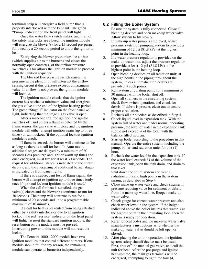
6.2 Filling the Boiler System1. Ensure the system is fully connected. Close all
bleeding devices and open make-up water valve.Allow system to fill slowly.
2. If make-up water pump is employed, adjustpressure switch on pumping system to provide aminimum of 12 psi (81.8 kPa) at the highestpoint in the heating loop.
3. If a water pressure regulator is provided on themake-up water line, adjust the pressure regulatorto provide at least 12 psi (81.8 kPa) at thehighest point in the heating loop.
4. Open bleeding devices on all radiation units atthe high points in the piping throughout thesystem, unless automatic air bleeders areprovided at such points.
5. Run system circulating pump for a minimum of30 minutes with the boiler shut off.
6. Open all strainers in the circulating system,check flow switch operation, and check fordebris. If debris is present, clean out to ensureproper circulation.
7. Recheck all air bleeders as described in Step 4.8. Check liquid level in expansion tank. With the
system full of water and under normal operatingpressure, the level of water in the expansion tankshould not exceed ¼ of the total, with thebalance filled with air.
9. Start up boiler according to the procedure in thismanual. Operate the entire system, including thepump, boiler, and radiation units for one (1)hour.
10. Recheck the water level in the expansion tank. Ifthe water level exceeds ¼ of the volume of theexpansion tank, open the tank drain, and drain tothat level.
11. Shut down the entire system and vent allradiation units and high points in the systempiping, as described in Step 4.
12. Close make-up water valve and check strainer inpressure reducing valve for sediment or debrisfrom the make-up water line. Reopen make-upwater valve.
13. Check gauge for correct water pressure and alsocheck water level in the system. If the heightindicated above the boiler insures that water is atthe highest point in the circulating loop, then thesystem is ready for operation.
14. Refer to local codes and the make-up water valvemanufacturer’s instructions as to whether themake-up water valve should be left open orclosed.
15. After placing the unit in operation, the ignitionsystem safety shutoff device must be tested.First, shut off the manual gas valve, and call theunit for heat. After the pre-purge and ignitorheat-up time, the main gas terminals will beenergized, attempting to light, for four (4)
terminals strip will energize a field pump that isproperly interlocked with the Pennant. The green“Pump” indicator on the front panel will light.
Once the water flow switch makes, and if all ofthe safety interlocks are closed, the ignition modulewill energize the blower(s) for a 15-second pre-purge,followed by a 20-second period to allow the ignitor toheat.
Energizing the blower pressurizes the air box(which supplies air to the burners) and closes thenormally-open contact(s) of the airflow pressureswitch(es). This allows the ignition module to proceedwith the ignition sequence.
The blocked flue pressure switch senses thepressure in the plenum. It will interrupt the airflowsensing circuit if this pressure exceeds a maximumvalue. If airflow is not proven, the ignition modulewill lockout.
The ignition module checks that the ignitorcurrent has reached a minimum value and energizesthe gas valve at the end of the ignitor heating period.The green “Stage 1” indicator on the front panel willlight, indicating that the stage 1 gas valve is open.
After a 4-second trial for ignition, the ignitorswitches off, and unless a flame is detected by theflame sensor, the gas valve will close and the ignitionmodule will either attempt ignition again (up to threetimes) or will lockout (if the optional lockout ignitionmodule is used).
If flame is sensed, the burner will continue to fireas long as there is a call for heat. In Auto mode,additional stages are delayed by a minimum of 60seconds (less prepurge and ignitor warm-up time) andonce energized, must fire for at least 30 seconds. Therequest for additional stages is indicated on the controldisplay, and the energizing of additional burner stagesis indicated by front panel lights.
If there is a subsequent loss of flame signal, theburner will attempt re-ignition up to three times (onlyonce if optional lockout ignition module is used.)
When the call for heat is satisfied, the gasvalve(s) closes and the blower(s) continues to run for30 seconds. The pump will continue to run for aminimum of 20 seconds and up to a programmablemaximum of 10 minutes.
If a call for heat is prevented from being satisfiedeither by a safety interlock or due to an ignitionlockout, the red “Service” indicator on the front panelwill light. To reset the standard ignition module, thereset button on the module must be pressed.Interrupting power to this module will not reset thelockout.
The Pennant 1000 - 2000 models have twoignition modules that control different burners. If onemodule should fail for any reason, the remainingmodule can operate its burner(s) independently.
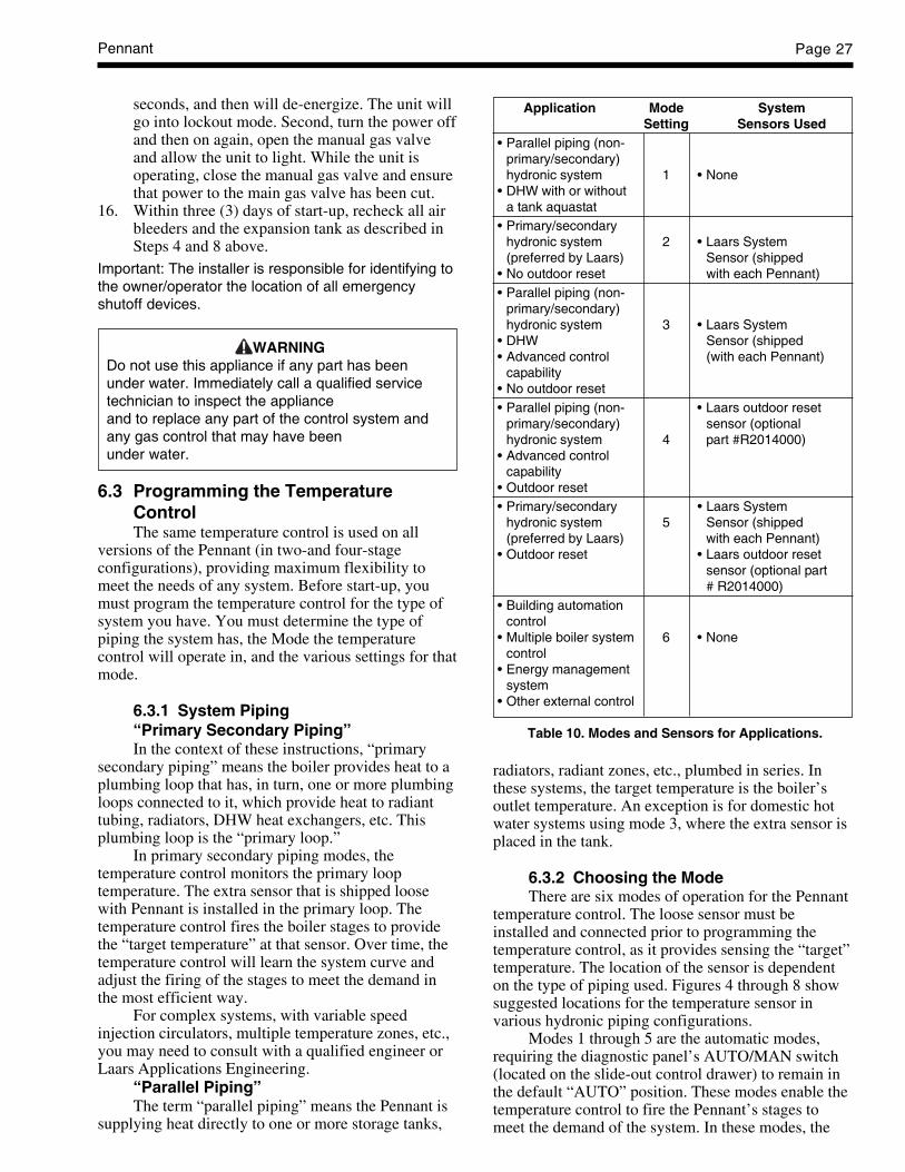
Pennant Page 27
radiators, radiant zones, etc., plumbed in series. Inthese systems, the target temperature is the boiler’soutlet temperature. An exception is for domestic hotwater systems using mode 3, where the extra sensor isplaced in the tank.
6.3.2 Choosing the ModeThere are six modes of operation for the Pennant
temperature control. The loose sensor must beinstalled and connected prior to programming thetemperature control, as it provides sensing the “target”temperature. The location of the sensor is dependenton the type of piping used. Figures 4 through 8 showsuggested locations for the temperature sensor invarious hydronic piping configurations.
Modes 1 through 5 are the automatic modes,requiring the diagnostic panel’s AUTO/MAN switch(located on the slide-out control drawer) to remain inthe default “AUTO” position. These modes enable thetemperature control to fire the Pennant’s stages tomeet the demand of the system. In these modes, the
seconds, and then will de-energize. The unit willgo into lockout mode. Second, turn the power offand then on again, open the manual gas valveand allow the unit to light. While the unit isoperating, close the manual gas valve and ensurethat power to the main gas valve has been cut.
16. Within three (3) days of start-up, recheck all airbleeders and the expansion tank as described inSteps 4 and 8 above.
Important: The installer is responsible for identifying tothe owner/operator the location of all emergencyshutoff devices.
WARNINGDo not use this appliance if any part has beenunder water. Immediately call a qualified servicetechnician to inspect the applianceand to replace any part of the control system andany gas control that may have beenunder water.
6.3 Programming the TemperatureControlThe same temperature control is used on all
versions of the Pennant (in two-and four-stageconfigurations), providing maximum flexibility tomeet the needs of any system. Before start-up, youmust program the temperature control for the type ofsystem you have. You must determine the type ofpiping the system has, the Mode the temperaturecontrol will operate in, and the various settings for thatmode.
6.3.1 System Piping“Primary Secondary Piping”In the context of these instructions, “primary
secondary piping” means the boiler provides heat to aplumbing loop that has, in turn, one or more plumbingloops connected to it, which provide heat to radianttubing, radiators, DHW heat exchangers, etc. Thisplumbing loop is the “primary loop.”
In primary secondary piping modes, thetemperature control monitors the primary looptemperature. The extra sensor that is shipped loosewith Pennant is installed in the primary loop. Thetemperature control fires the boiler stages to providethe “target temperature” at that sensor. Over time, thetemperature control will learn the system curve andadjust the firing of the stages to meet the demand inthe most efficient way.
For complex systems, with variable speedinjection circulators, multiple temperature zones, etc.,you may need to consult with a qualified engineer orLaars Applications Engineering.
“Parallel Piping”The term “parallel piping” means the Pennant is
supplying heat directly to one or more storage tanks,
Application Mode SystemSetting Sensors Used
• Parallel piping (non-primary/secondary)hydronic system 1 • None
• DHW with or withouta tank aquastat
• Primary/secondaryhydronic system 2 • Laars System(preferred by Laars) Sensor (shipped
• No outdoor reset with each Pennant)• Parallel piping (non-
primary/secondary)hydronic system 3 • Laars System
• DHW Sensor (shipped• Advanced control (with each Pennant)
capability• No outdoor reset• Parallel piping (non- • Laars outdoor reset
primary/secondary) sensor (optionalhydronic system 4 part #R2014000)
• Advanced controlcapability
• Outdoor reset• Primary/secondary • Laars System
hydronic system 5 Sensor (shipped(preferred by Laars) with each Pennant)
• Outdoor reset • Laars outdoor resetsensor (optional part# R2014000)
• Building automationcontrol
• Multiple boiler system 6 • Nonecontrol
• Energy managementsystem
• Other external control
Table 10. Modes and Sensors for Applications.

LAARS Heating SystemsPage 28
FOR ALL OTHER MODES:BOIL MASS (Boiler Mass): Always choose “1”.BOIL TARGET (Boiler Target Temperature):
Your desired set-point temperature. See section 6.4.5and Figure 16 for more information.
BOIL MIN (Boiler Minimum Temperature):This setting tells the Temperature Control to maintainat least this temperature, even if the PID logicdetermines a lower setting would save energy. TheBOIL MIN should always be 120°F (49°C) or higherto prevent condensation, and can be set up to 10°Fbelow your BOIL TARGET temperature. See section6.4.3 for more information.
BOIL MAX (Boiler Maximum Temperature):This setting tells the Temperature Control to limit themaximum outlet temperature to this setting or below,and determines how quickly the temperature control“stages down” or off. If the BOIL MAX setting ismuch higher than the BOIL TARGET temperature, thetemperature control will fire all stages until the target
Pennant temperature control continuously samples theinlet, outlet and target temperatures.
Mode 6 is the “Manual” mode, and the AUTO/MAN switch must be moved to the “MAN” position.An external control, such as a building automationsystem or multiple boiler control, just be wired to thefield wiring panel in order to fire the boiler, bypassingthe temperature control. (See Section 5.3 for importantinformation about external staging controls andbuilding automation systems.)
Table 10 contains information to identify themode you should use for your system.
6.3.3 ProgrammingBefore programming, you must determine the
type of piping you have, the mode you will use, andinstall the extra sensor if required for that mode. Seesections 6.3.1 and 6.3.2 for more information, orcontact the factory.
Figure 15. Temperature Control.
There are three black programming buttons onthe Temperature Control (see Figure 15). Press andhold all three programming buttons until the word“ADJUST” appears in the upper right corner of theLCD display (it replaces the word “VIEW”).
Pressing “Item” cycles you through the itemsyou need to program. “Up Arrow” increases the valueof that item, while “Down Arrow” decreases it.“ADJUST” mode exits if you don’t press a button for20 seconds. To return to “ADJUST” mode, simplypress and hold the three buttons again.
The first item is “Mode”; enter the mode numberas determined above. The Temperature Control willthen present you with some or all of the followingoptions, depending on the mode you have chosen:
In mode 6, external boiler control, you will notsee the following options. Refer to manual, section6.4.10, for setup information for mode 6.
Figure 16. Temperature Control Symbol Description.
Setp Dem
Item
VIEW ADJUST
°F
°Cmin
OUTDR DSGN DIFF
BOILSUPINOUT
STARTMINMAX
TONOFFDLY
TARGETMASS
TANKSTGMODE
WWSD
Dem
1 23 4
Item FieldDisplays an abbreviatedname of the selected item
Number FieldDisplays the currentvalue of the selecteditem
Menu FieldDisplays thecurrent menu
Status FieldDisplays thecurrent statusof the control'sinputs, outputsand operation
ButtonsSelects Menus,Items andadjusts settings
Figure 17. Temperature Control Target TemperatureGraph.

Pennant Page 29
temperature is reached, and then shut down all stagesat once. To enable gradual staging down of the boileras you approach your target temperature, set the BOILMAX to the same setting as the target temperature.See section 6.4.4 for more information.
DIFF (Boiler Differential): This setting isdivided above and below the target temperature. Thewater will be allowed to cool ½ this setting below thetarget temperature before first stage fires, and will heatto ½ this setting above the target temperature beforestaging the boiler down. See Section 6.4.1 and Figure18 for more information.
PUMP DLY (Pump Delay): On pump mountedunits, the boiler mounted pump continues to run forthe time selected after the heat demand in the system issatisfied. This setting also affects the 24VAC outputon the “PMP” “PMP” terminals (see section 5.2).These terminals can power a contactor for a largersystem pump. Laars recommends a minimum pumpdelay setting of 5 minutes. See section 6.4.6 for moreinformation. Note: In modes other than mode 6, thepump will run continuously if the “HtD” and“ComD” terminals are jumpered and not connected toa zone valve or pump end switch, or other “contactclosure” device to indicate when the heat demand inthe system is satisfied. The pump will never run, andthe boiler will never fire, if the jumper is removed andthe terminals left empty.
OUTDOOR RESET (Modes 4 and 5) Outdoorreset adjusts the target temperature based on theoutdoor air temperature and reset ratio. The reset ratiois determined from the Boiler Start, Boiler Design,Outdoor Start and Outdoor Design settings.
HEAT DEMAND – For heat demand to exist,there must be continuity between the Com D (commondemand) and Ht D (heat demand) terminals. ThePennant ships with a jumper between these terminals.
The control also evaluates the sensor(s) installedin the system. If the control is not in warm weathershutdown (WWSD), and the sensor(s) are below thetarget temperature, the “Dem” segment is turned on inthe display. The control energizes the pump (on pumpmounted boilers) and energizes the “PMP-“PMP”terminals. The pump symbol appears in the display(see Figures 16 and 17). The control then operates thestages to maintain the setpoint temperature.
Boiler Start (BOIL START) The BOIL STARTtemperature is the theoretical boiler supplytemperature that the heating system requires when theoutdoor air temperature equals the OUTDR STARTtemperature setting.
EXAMPLE 1DHW (Mode 3) Programming. For domestic
hot water systems up to 175°F / 79°C, use Mode 3 asdescribed below.
Step 1: Install the additional sensor into thestorage tank, wiring it to “SC2” and “SUPS” terminalson the field wiring panel (Figure 32).
Step 2: Press the three programming buttons toenter “ADJUST” mode (Figure 15). Press “Item” toselect the programming item, and the arrow keys toadjust the setting. “TARGET TANK” is desired tanktemperature. Recommended settings with a desiredtank temperature of 125°F:
Example DHW Programming
Item F° C°MODE 3 3BOIL TARGET 140°F 60°CTARGET TANK 125°F 52°CDIFF TANK 2°F 1°CBOIL MASS 1 1DIFF 2°F 1°CDLY 5:00 5:00F° F° °C
Step 4: See section 6.4.11 Limit Controls. Setboth high limits 25°F / 14°C higher than “BOILTARGET” to allow for temperature rise across heatexchanger. Manual high limits on water heaters have amaximum 200°F / 93°C setting. (If water must be at175°F / 79°C or higher with a volume water heatermodel, use Mode 1. For volume water applicationsexceeding 200°F / 93°C, contact the factory.)
Fine tuning: For faster staging, increase “BOILTARGET” setting. Larger “DIFF TANK” and “DIFF”settings will slow response to demand, but may saveenergy.
If unit short cycles, enter AdvancedProgramming mode (Section 6.4) and increase“BOILER MAX” setting to the “BOIL TARGET”setting or higher. Set “BOILER MIN” to 120°F /49°C, and “STGMODE” to PID. See section 6.4.12Advanced Programming Mode to enter AdvancedProgramming mode, or contact the factory forassistance.
EXAMPLE 2Hydronic Primary/Secondary (Mode 2)
Programming. MODE 2 is used in primary-secondary piping hydronic systems without outdoorreset. Mode 5 adds outdoor reset.
Step 1: Install the additional sensor in theprimary loop. This sensor should be installed as perSection 6.3.4 under Primary Secondary Piping in thismanual, and wired to the “SC2” and “SUPS” terminalson the field wiring panel (Figure 32).
Step 2: Remove the factory-installed jumperbetween the “HtD” and “ComD” terminals on the fieldwiring panel (Figure 32), and connect a zone valve orpump end switch or other contact closure device(aquastat, etc.) to these terminals to provide anindication of heat demand in the system.
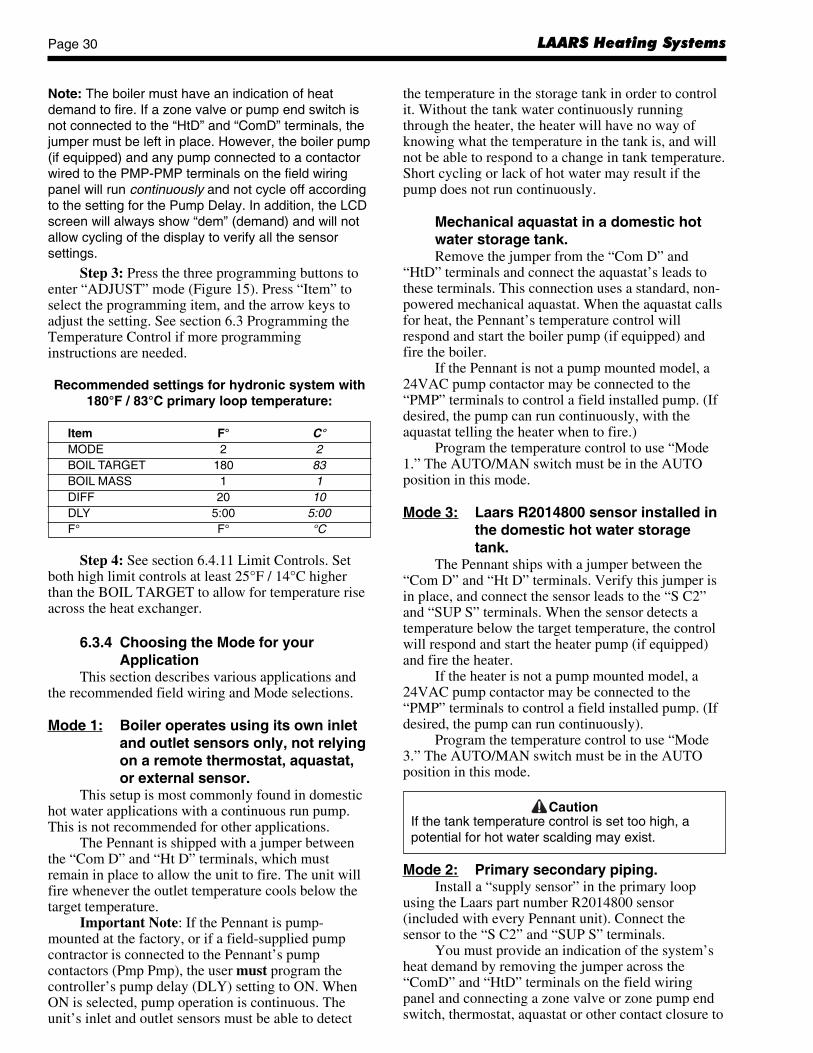
LAARS Heating SystemsPage 30
Note: The boiler must have an indication of heatdemand to fire. If a zone valve or pump end switch isnot connected to the “HtD” and “ComD” terminals, thejumper must be left in place. However, the boiler pump(if equipped) and any pump connected to a contactorwired to the PMP-PMP terminals on the field wiringpanel will run continuously and not cycle off accordingto the setting for the Pump Delay. In addition, the LCDscreen will always show “dem” (demand) and will notallow cycling of the display to verify all the sensorsettings.
Step 3: Press the three programming buttons toenter “ADJUST” mode (Figure 15). Press “Item” toselect the programming item, and the arrow keys toadjust the setting. See section 6.3 Programming theTemperature Control if more programminginstructions are needed.
Recommended settings for hydronic system with180°F / 83°C primary loop temperature:
Item F° C°MODE 2 2BOIL TARGET 180 83BOIL MASS 1 1DIFF 20 10DLY 5:00 5:00F° F° °C
Step 4: See section 6.4.11 Limit Controls. Setboth high limit controls at least 25°F / 14°C higherthan the BOIL TARGET to allow for temperature riseacross the heat exchanger.
6.3.4 Choosing the Mode for yourApplication
This section describes various applications andthe recommended field wiring and Mode selections.
Mode 1: Boiler operates using its own inletand outlet sensors only, not relyingon a remote thermostat, aquastat,or external sensor.
This setup is most commonly found in domestichot water applications with a continuous run pump.This is not recommended for other applications.
The Pennant is shipped with a jumper betweenthe “Com D” and “Ht D” terminals, which mustremain in place to allow the unit to fire. The unit willfire whenever the outlet temperature cools below thetarget temperature.
Important Note: If the Pennant is pump-mounted at the factory, or if a field-supplied pumpcontractor is connected to the Pennant’s pumpcontactors (Pmp Pmp), the user must program thecontroller’s pump delay (DLY) setting to ON. WhenON is selected, pump operation is continuous. Theunit’s inlet and outlet sensors must be able to detect
the temperature in the storage tank in order to controlit. Without the tank water continuously runningthrough the heater, the heater will have no way ofknowing what the temperature in the tank is, and willnot be able to respond to a change in tank temperature.Short cycling or lack of hot water may result if thepump does not run continuously.
Mechanical aquastat in a domestic hotwater storage tank.Remove the jumper from the “Com D” and
“HtD” terminals and connect the aquastat’s leads tothese terminals. This connection uses a standard, non-powered mechanical aquastat. When the aquastat callsfor heat, the Pennant’s temperature control willrespond and start the boiler pump (if equipped) andfire the boiler.
If the Pennant is not a pump mounted model, a24VAC pump contactor may be connected to the“PMP” terminals to control a field installed pump. (Ifdesired, the pump can run continuously, with theaquastat telling the heater when to fire.)
Program the temperature control to use “Mode1.” The AUTO/MAN switch must be in the AUTOposition in this mode.
Mode 3: Laars R2014800 sensor installed inthe domestic hot water storagetank.
The Pennant ships with a jumper between the“Com D” and “Ht D” terminals. Verify this jumper isin place, and connect the sensor leads to the “S C2”and “SUP S” terminals. When the sensor detects atemperature below the target temperature, the controlwill respond and start the heater pump (if equipped)and fire the heater.
If the heater is not a pump mounted model, a24VAC pump contactor may be connected to the“PMP” terminals to control a field installed pump. (Ifdesired, the pump can run continuously).
Program the temperature control to use “Mode3.” The AUTO/MAN switch must be in the AUTOposition in this mode.
CautionIf the tank temperature control is set too high, apotential for hot water scalding may exist.
Mode 2: Primary secondary piping.Install a “supply sensor” in the primary loop
using the Laars part number R2014800 sensor(included with every Pennant unit). Connect thesensor to the “S C2” and “SUP S” terminals.
You must provide an indication of the system’sheat demand by removing the jumper across the“ComD” and “HtD” terminals on the field wiringpanel and connecting a zone valve or zone pump endswitch, thermostat, aquastat or other contact closure to
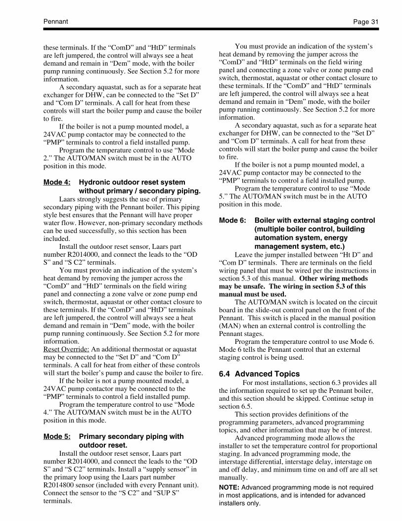
Pennant Page 31
these terminals. If the “ComD” and “HtD” terminalsare left jumpered, the control will always see a heatdemand and remain in “Dem” mode, with the boilerpump running continuously. See Section 5.2 for moreinformation.
A secondary aquastat, such as for a separate heatexchanger for DHW, can be connected to the “Set D”and “Com D” terminals. A call for heat from thesecontrols will start the boiler pump and cause the boilerto fire.
If the boiler is not a pump mounted model, a24VAC pump contactor may be connected to the“PMP” terminals to control a field installed pump.
Program the temperature control to use “Mode2.” The AUTO/MAN switch must be in the AUTOposition in this mode.
Mode 4: Hydronic outdoor reset systemwithout primary / secondary piping.
Laars strongly suggests the use of primarysecondary piping with the Pennant boiler. This pipingstyle best ensures that the Pennant will have properwater flow. However, non-primary secondary methodscan be used successfully, so this section has beenincluded.
Install the outdoor reset sensor, Laars partnumber R2014000, and connect the leads to the “ODS” and “S C2” terminals.
You must provide an indication of the system’sheat demand by removing the jumper across the“ComD” and “HtD” terminals on the field wiringpanel and connecting a zone valve or zone pump endswitch, thermostat, aquastat or other contact closure tothese terminals. If the “ComD” and “HtD” terminalsare left jumpered, the control will always see a heatdemand and remain in “Dem” mode, with the boilerpump running continuously. See Section 5.2 for moreinformation.Reset Override: An additional thermostat or aquastatmay be connected to the “Set D” and “Com D”terminals. A call for heat from either of these controlswill start the boiler’s pump and cause the boiler to fire.
If the boiler is not a pump mounted model, a24VAC pump contactor may be connected to the“PMP” terminals to control a field installed pump.
Program the temperature control to use “Mode4.” The AUTO/MAN switch must be in the AUTOposition in this mode.
Mode 5: Primary secondary piping withoutdoor reset.
Install the outdoor reset sensor, Laars partnumber R2014000, and connect the leads to the “ODS” and “S C2” terminals. Install a “supply sensor” inthe primary loop using the Laars part numberR2014800 sensor (included with every Pennant unit).Connect the sensor to the “S C2” and “SUP S”terminals.
You must provide an indication of the system’sheat demand by removing the jumper across the“ComD” and “HtD” terminals on the field wiringpanel and connecting a zone valve or zone pump endswitch, thermostat, aquastat or other contact closure tothese terminals. If the “ComD” and “HtD” terminalsare left jumpered, the control will always see a heatdemand and remain in “Dem” mode, with the boilerpump running continuously. See Section 5.2 for moreinformation.
A secondary aquastat, such as for a separate heatexchanger for DHW, can be connected to the “Set D”and “Com D” terminals. A call for heat from thesecontrols will start the boiler pump and cause the boilerto fire.
If the boiler is not a pump mounted model, a24VAC pump contactor may be connected to the“PMP” terminals to control a field installed pump.
Program the temperature control to use “Mode5.” The AUTO/MAN switch must be in the AUTOposition in this mode.
Mode 6: Boiler with external staging control(multiple boiler control, buildingautomation system, energymanagement system, etc.)
Leave the jumper installed between “Ht D” and“Com D” terminals. There are terminals on the fieldwiring panel that must be wired per the instructions insection 5.3 of this manual. Other wiring methodsmay be unsafe. The wiring in section 5.3 of thismanual must be used.
The AUTO/MAN switch is located on the circuitboard in the slide-out control panel on the front of thePennant. This switch is placed in the manual position(MAN) when an external control is controlling thePennant stages.
Program the temperature control to use Mode 6.Mode 6 tells the Pennant control that an externalstaging control is being used.
6.4 Advanced TopicsFor most installations, section 6.3 provides all
the information required to set up the Pennant boiler,and this section should be skipped. Continue setup insection 6.5.
This section provides definitions of theprogramming parameters, advanced programmingtopics, and other information that may be of interest.
Advanced programming mode allows theinstaller to set the temperature control for proportionalstaging. In advanced programming mode, theinterstage differential, interstage delay, interstage onand off delay, and minimum time on and off are all setmanually.NOTE: Advanced programming mode is not requiredin most applications, and is intended for advancedinstallers only.
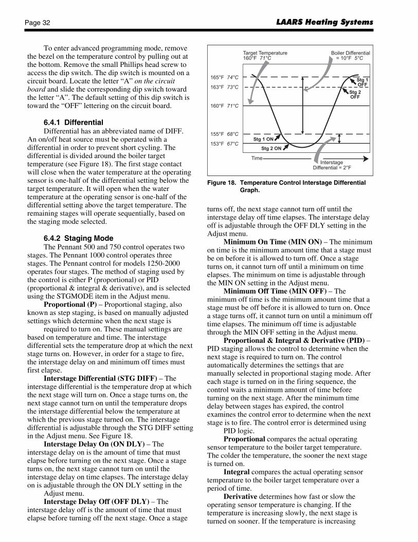
LAARS Heating SystemsPage 32
turns off, the next stage cannot turn off until theinterstage delay off time elapses. The interstage delayoff is adjustable through the OFF DLY setting in theAdjust menu.
Minimum On Time (MIN ON) – The minimumon time is the minimum amount time that a stage mustbe on before it is allowed to turn off. Once a stageturns on, it cannot turn off until a minimum on timeelapses. The minimum on time is adjustable throughthe MIN ON setting in the Adjust menu.
Minimum Off Time (MIN OFF) – Theminimum off time is the minimum amount time that astage must be off before it is allowed to turn on. Oncea stage turns off, it cannot turn on until a minimum offtime elapses. The minimum off time is adjustablethrough the MIN OFF setting in the Adjust menu.
Proportional & Integral & Derivative (PID) –PID staging allows the control to determine when thenext stage is required to turn on. The controlautomatically determines the settings that aremanually selected in proportional staging mode. Aftereach stage is turned on in the firing sequence, thecontrol waits a minimum amount of time beforeturning on the next stage. After the minimum timedelay between stages has expired, the controlexamines the control error to determine when the nextstage is to fire. The control error is determined using
PID logic.Proportional compares the actual operating
sensor temperature to the boiler target temperature.The colder the temperature, the sooner the next stageis turned on.
Integral compares the actual operating sensortemperature to the boiler target temperature over aperiod of time.
Derivative determines how fast or slow theoperating sensor temperature is changing. If thetemperature is increasing slowly, the next stage isturned on sooner. If the temperature is increasing
To enter advanced programming mode, removethe bezel on the temperature control by pulling out atthe bottom. Remove the small Phillips head screw toaccess the dip switch. The dip switch is mounted on acircuit board. Locate the letter “A” on the circuitboard and slide the corresponding dip switch towardthe letter “A”. The default setting of this dip switch istoward the “OFF” lettering on the circuit board.
6.4.1 DifferentialDifferential has an abbreviated name of DIFF.
An on/off heat source must be operated with adifferential in order to prevent short cycling. Thedifferential is divided around the boiler targettemperature (see Figure 18). The first stage contactwill close when the water temperature at the operatingsensor is one-half of the differential setting below thetarget temperature. It will open when the watertemperature at the operating sensor is one-half of thedifferential setting above the target temperature. Theremaining stages will operate sequentially, based onthe staging mode selected.
6.4.2 Staging ModeThe Pennant 500 and 750 control operates two
stages. The Pennant 1000 control operates threestages. The Pennant control for models 1250-2000operates four stages. The method of staging used bythe control is either P (proportional) or PID(proportional & integral & derivative), and is selectedusing the STGMODE item in the Adjust menu.
Proportional (P) – Proportional staging, alsoknown as step staging, is based on manually adjustedsettings which determine when the next stage is
required to turn on. These manual settings arebased on temperature and time. The interstagedifferential sets the temperature drop at which the nextstage turns on. However, in order for a stage to fire,the interstage delay on and minimum off times mustfirst elapse.
Interstage Differential (STG DIFF) – Theinterstage differential is the temperature drop at whichthe next stage will turn on. Once a stage turns on, thenext stage cannot turn on until the temperature dropsthe interstage differential below the temperature atwhich the previous stage turned on. The interstagedifferential is adjustable through the STG DIFF settingin the Adjust menu. See Figure 18.
Interstage Delay On (ON DLY) – Theinterstage delay on is the amount of time that mustelapse before turning on the next stage. Once a stageturns on, the next stage cannot turn on until theinterstage delay on time elapses. The interstage delayon is adjustable through the ON DLY setting in the
Adjust menu.Interstage Delay Off (OFF DLY) – The
interstage delay off is the amount of time that mustelapse before turning off the next stage. Once a stage
Figure 18. Temperature Control Interstage DifferentialGraph.

Pennant Page 33
quickly, the next stage is turned on later, if at all.Boiler Mass (BOIL MASS) – The boiler mass
setting allows the installer to adjust the control to thethermal mass of different types of heat sources used.The boiler mass setting automatically determines theinterstage differential, interstage delay on, interstagedelay off, minimum on time and minimum off time ofthe stages when PID staging is used. A higher thermalmass setting provides slower staging, while a lowerthermal mass setting provides faster staging. Pennantboilers and water heaters are low-mass appliances, andtherefore, should be used with the lower thermal masssetting. Set BOIL MASS to “1”.
6.4.3 Boiler Minimum (BOIL MIN)The minimum boiler setting (BOIL MIN) is the
lowest water temperature that the control is allowed touse as a target temperature. During mild conditions, ifthe control calculates a target temperature that isbelow this setting, the target temperature is adjusted toat least the minimum setting. During this condition, ifthe unit is operating, the MIN segment turns on in theLCD while the target temperature or operating sensortemperature is viewed. For Pennant units, this must beset no lower than 120°F (49°C) to protect the unitfrom condensing on the heat exchanger (see Figure 19).
6.4.4 Boiler Maximum (BOIL MAX)The boiler maximum (BOIL MAX) is the highest
water temperature that the control is allowed to use asa target temperature. If the control does target BOILMAX, and the boiler outlet sensor is near the BOILMAX temperature, the MAX segment turns on in theLCD while the target, inlet, outlet or supplytemperature is viewed (see Figure 19).
6.4.5 Boiler Target TemperatureThe target temperature is determined from the
mode of operation. The control displays thetemperature that is currently trying to maintain at theoperating sensor as BOIL TARGET in the Viewmenu. The operating sensor for modes 1, 3 and 4 is theoutlet sensor (on the Pennant). The operating sensorfor modes 2 and 5 is the supply sensor (in the systemor primary loop). If the control does not presentlyhave a requirement for heat, it displays “- - -” in theLCD. There is no target temperature generated inmode 6 (external controller mode).
6.4.6 Pump OperationThe pump terminals (Pmp Pmp) are energized
with 24 VAC to control a field supplied pumpcontactor. During setpoint operation (modes 1 and 2),the terminals are energized whenever there is a heatdemand. During dedicated DHW operation (mode 3),the terminals are energized whenever there is aninternal heat demand. During outdoor reset (modes 4and 5), the terminals are energized whenever there iseither a heat demand and the control is not in WarmWeather Shut Down (WWSD), or whenever there is asetpoint demand. During WWSD, if the pump has notoperated at least once every 70 hours, the controlenergizes the terminals for 10 seconds. This minimizesthe possibility of the pump seizing during a longperiod of inactivity. During External Boiler Operation(mode 6), the pump contact closes whenever there is aheat demand.
Boiler Purge (PUMP DLY) – After a demand issatisfied, the control continues to operate the pump fora period of time. The length of time that the pumpcontinues to run is based on the pump delay setting.Once the last stage of the control turns off, the control
keeps the pump contacts energized for the timeselected (between 0 and 10 minutes). When OFF isselected, there is no purging. When ON is selected,pump operation is continuous. Also, during outdoorreset, with the pump delay set to ON, the pumpcontinues to run even during Warm Weather ShutDown.
6.4.7 Setpoint OperationWhen either mode 1 or 2 is selected, the control
controls the water temperature based on a fixedsetpoint. The setpoint temperature is set using theBOIL TARGET item in the Adjust menu.
Figure 19. Temperature Control Min & Max Graph.

LAARS Heating SystemsPage 34
Heat Demand – For “heat demand” to exist,there must be continuity between the Com D (commondemand) and the Ht D (heat demand) terminals. ThePennant ships with a jumper between these terminals.
The control also evaluates the sensor(s) installedin the system, including the outlet sensor provided onthe boiler when using mode 1. When the controlsenses continuity between Com D and Ht D terminals,and that the sensor reading is below the targettemperature, the control will activate the Dem segmentin the display.
The control energizes the pump (on pumpmounted boilers) and energizes the Pmp Pmpterminals. The boiler pump segment is turned on in thedisplay. The control then operates the stages tomaintain the setpoint temperature.
6.4.8 Dedicated Domestic Hot WaterWhen mode 3 is selected, the control provides
dedicated domestic hot water operation.Internal DHW Demand – A sensor is required
to be connected on the SC2 and Sup/S terminals. Aninternal demand for DHW is generated when thetemperature demand for DHW sensor drops ½ of thetank differential setting below the desired DHW tanktemperature. The TANK TARGET setting is used toset the desired DHW tank temperature.
Once an internal demand is generated, the Demsegment turns on in the LCD. The control then closesthe Pmp Pmp contact, which starts the pump and thecontrol turns on the boiler pump segment in thedisplay. The control then operates the stages tomaintain the programmed boiler target temperature atthe boiler outlet sensor.
The boiler target temperature is set using theBOIL TARGET item in the Adjust menu. Note:External demand is not required in this mode ofoperation.
Tank Differential – A differential setting thatoperates ½ above and below the TANK TARGET isselectable using the TANK DIFF item in the Adjustmenu.
6.4.9 Outdoor Reset OperationWhen either mode 4 or 5 is selected, the control
uses outdoor reset to control the water temperature.Outdoor reset adjusts the target temperature based onthe outdoor air temperature and reset ratio. The resetratio is determined from the Boiler Start, BoilerDesign, Outdoor Start and Outdoor Design settings.
Heat Demand – For “heat demand” to exist,there must be continuity between the Com D (commondemand) and the Ht D (heat demand) terminals. ThePennant ships with a jumper between these terminals.
The control also evaluates the sensor(s) installedin the system. If the control is not in warm weathershutdown (WWSD), and the sensor(s) are below thetarget temperature, the Dem segment is turned on in
the display. The control energizes the pump (on pumpmounted boilers) and energizes the Pmp-Pmpterminals, and the boiler pump segment is turned on inthe display. The control then operates the stages tomaintain the setpoint temperature.
Boiler Start (BOIL START) – The BOILSTART temperature is the theoretical boiler supplywater temperature that the heating system requireswhen the outdoor air temperature equals the OUTDRSTART temperature setting. The BOIL START istypically set to the desired building temperature (seeFigure 20).
Outdoor Start (OUTDR START) – TheOUTDR START temperature is the outdoor airtemperature at which the control provides the BOILSTART water temperature to the system. The OUTDRSTART is typically set to the desired buildingtemperature.
Outdoor Design (OUTDR DSGN) – TheOUTDR DSGN is the outdoor air temperature that isthe typical coldest temperature of the year where thebuilding is located. This temperature is used whendoing heat loss calculations for the building.
Boiler Design (BOIL DSGN) – The BOILDSGN temperature is the water temperature requiredto heat the boiler zones when the outdoor air is as coldas the OUTDR DSGN temperature.
Warm Weather Shut Down (WWSD) – Whenthe outdoor air temperature rises above the WWSDsetting, the control turns on the WWSD segment in thedisplay. When the control is in WWSD, the Demsegment is displayed if there is a heat demand.
Figure 20. Temperature Control Outdoor Start Graph.

Pennant Page 35
Figure 21. Typical Gas Train Configuration.
Figure 22. Typical Control Panel.
However, the control does not operate the heatingsystem to satisfy this demand. The control doesrespond to a setpoint demand and operates asdescribed in the Reset Override section (next).
Reset Override (SETPOINT DEMAND) –This is used when override of the outdoor reset curveis needed, such as when an indirect water heater isserved by the heating system. A setpoint demand isrequired whenever heat is required for the setpointload. The setpoint demand overrides the reset watertemperature. The control turns on the Setp Dempointer in the display. The control energizes the pump(on pump-mounted boilers), energizes the Pmp-Pmpterminals, and turns on the boiler pump segment in thedisplay. The control then operates the boiler stages tomaintain the programmed boiler target temperature.The reset override operation is not affected byWWSD.
6.4.10 External Boiler OperationWhen mode 6 is selected, the control allows for
an external control to operate the Pennant’s stages. Inthis mode, the control operates the pump in order toprovide purging and exercising. The staging operationis provided by an external device such as an EnergyManagement System (EMS) or External StagingControl.

LAARS Heating SystemsPage 36
Heat Demand – A heat demand is generatedwhen stage one is wired properly, and the externalcontrol closes the contacts on the stage one terminals(1C-1NO), calling the Pennant for heat. The Pennantis shipped with a jumper between the Com D and Ht Dterminals, and this jumper must remain in place whenand external control is providing the heat demandsignal to these terminals. The control energizes theboiler pump (if equipped), energizes the Pmp-Pmpterminals, and turns on the boiler pump segment in thedisplay. The control also turns on stage 1 of the boiler.Section 5.3 contains important information aboutexternal staging controls and building automationsystems. Other wiring methods may be unsafe. Thewiring in Section 5.3 of this manual must be used.
6.4.11 Limit ControlsIn addition to the temperature control, Pennant
appliances are fitted with a manual reset high limit andan automatic reset high limit. These are located nearthe rear of the cabinet on the right side, behind theslide out drawer (see Figure 22). Both controls shouldbe set at least 25°F higher than the target temperatureto avoid short cycling. To set these controls, removethe control panel cover and pull the control panel outto gain access. Appliances with reversed heatexchangers have the limit controls relocated to the leftside of the appliance. The left access door must beremoved to gain access to the limit controls on theseappliances.
6.4.12 Advanced Programming ModeAdvanced programming mode allows the
installer to set the temperature control for proportionalstaging. In advanced programming mode, theinterstage differential, interstage delay, interstage onand off delay, and minimum time on and off are all setmanually.NOTE: Advanced programming mode is rarelyrequired. It is intended for advanced installers, andonly when the application demands suchprogramming.
To enter advanced programming mode, removethe bezel on the temperature control by pulling out atthe bottom. Remove the small Phillips head screw toaccess the dip switch. The dip switch is mounted on acircuit board.
Locate the letter “A” on the circuit board andslide the corresponding dip switch toward the letter“A”. The default setting of this dip switch is towardthe “OFF” lettering on the circuit board.
6.5 Operating the Burner and Set Up6.5.1 Set Up for 0 to 2500 Feet AltitudeThe Pennant appliance utilizes a modular design
to achieve its stage-firing. The setup must be checkedbefore the unit is put in operation. Problems such as
failure to start, rough ignition, strong exhaust odors,etc. can be due to improper setup. Damage to thePennant resulting from improper setup is not coveredby the limited warranty.1. Using this manual, make sure the installation is
complete and fully in compliance with theinstructions.
2. Determine that the appliance and system arefilled with water and all air has been bled fromboth. Open all valves.
3. Observe all warnings on the OperatingInstructions label and turn on gas and electricalpower to appliance.
4. Switch on the appliance power switch located onthe right side of the unit.
5. The Pennant will enter the start sequence, as longas the unit is being called for heat. The blowerand pump come on for pre-purge, then the ignitorwarm-up sequence starts and after the ignitorwarm-up is complete and all safety devices areverified, the gas valves open. If ignition doesn’toccur, check that there is proper gas supply. Wait5 minutes and start the unit again. During initialstart up, air in the gas line may cause the Pennantto "lock out" during the first few trials forignition. Depending on the ignition modulesinstalled, the manual reset button on the ignitionmodules may need to be depressed to restart thePennant.
6. When the unit is running, the supply gas pressuremust be checked. Inlet gas pressure must notexceed 13" W.C. (3.2kPa). The minimum inletgas pressure is 5" W.C. (1.2kPa).
7. Once the inlet gas pressure is verified, the outletgas pressure from each valve (manifold gaspressure) must be checked, and adjusted, ifnecessary. The manifold gas pressure must be2.5" W.C. (0.62kPa).
8. Complete the setup by checking the CO2 at theoutlet of the unit. The CO2 should be 8% fornatural gas, or 9.2% for propane.
9. After placing the appliance in operation, theBurner Safety Shutoff Device must be tested.To test:(a) Close gas shutoff valve with burner
operating.(b) The flame will go out and blower will
continue to run for the post purge cycle.One additional attempt to light will follow.Ignition will not occur as the gas is off. Theignition control will lockout, and will haveto be reset before the unit will operate.
(c) Open gas shutoff valve. Restart theappliance. The ignition sequence will startagain and the burner will start. Theappliance will return to its previous modeof operation.

Pennant Page 37
adjusted. Open the air shutter(s) to reduce the CO2 or
O2 to the values achieved previously.
The procedure is complete when all gas valvesare adjusted to a manifold pressure of 3.0 in. W.C.(0.75 kPa) and the CO
2 is adjusted to 8.0% for Natural
Gas appliances or 9.2% for LP appliances. Whenusing an O
2 analyzer, the correct O
2 is 6.8% for both
Natural Gas and LP appliances.
CautionShould any odor of gas be detected, or if the gasburner does not appear to be functioning in anormal manner, close main shutoff valve, do notshut off switch, and contact your heating contractor,gas company, or factory representative.
6.6 Shutting Down the Pennant1. Switch off the main electrical disconnect switch.2. Close all manual gas valves.3. If freezing is anticipated, drain the Pennant and
be sure to also protect building piping fromfreezing.This step to be performed by a qualifiedservice person.
6.7 To Restart the PennantIf drained, follow Section 6.1 in this manual for
proper filling and purging.1. Switch off the main electrical disconnect switch.2. Close all manual gas valves.3. WAIT FIVE (5) MINUTES.4. Set the aquastat or thermostat to its lowest
setting.5. Open all manual gas valves.6. Reset all safety switches (pressure switch,
manual reset high limit, etc.).7. Set the temperature controller to the desired
temperature setting and switch on electricalpower.
8. Burner will go through a prepurge period andignitor warm-up period, followed by ignition.
SECTION 7.Maintenance
7.1 System Maintenance1. Lubricate the system water-circulating pump, if
required, per the instructions on the pump.2. If a strainer is employed in a pressure reducing
valve or the piping, clean it every six months.3. Inspect the venting system for obstruction or
leakage at least once a year. Periodically cleanthe screens in the vent terminal and combustionair terminal (when used).
NOTE: Models 1000 - 2000 have two ignition controlsand two ignitors, which work independently of oneanother. If the ignition control for stages 1 and 2 failsto properly light the main burners for those stages, thesecond ignition control will still be active, and will beable to energize stages 3 and 4. This, of course, willonly occur if all other safety devices confirm that theunit will run in a safe condition.
6.5.2 High Altitude Adjustment and Set UpPennant appliances may be operated at high altitude
(7700 ft., 2347 m) with a reduction in output ofapproximately 10%. At altitudes of less than or more than7700 ft. (2347 m) the appliance will perform equally aswell, but with differing reductions in output. Atelevations higher than 7700 ft. (2347 m) the reduction inoutput will exceed 10% and at elevations below 7700 ft.(2347 m) it will be less than 10%. High altitudeadjustment must not be made on appliances operating atelevations below 2500 ft. (762 m).
No orifice changes are required to adjust thePennant appliances for high altitude. High altitudeadjustment is accomplished by adjustment of the gasvalve manifold pressure and the air shutter(s). Therequired instruments used to assist in theseadjustments are a CO
2 or O
2 Analyzer and a U-Tube
Manometer or other device capable of reading apressure of 2.5-3.0 inches W.C. (0.62-0.75 kPa).
Start the adjustment process by checking theCO2 in the “as installed” condition. Adjust the airshutter(s) so that the CO
2 is about 8% or the O
2 is
about 6.8% for appliances operating on Natural Gas.For appliances operating on LP Gas adjust the airshutter(s) so that the CO
2 is about 9.2% or the O
2 is
about 6.8%. Appliances with two blowers should beadjusted so that the air shutters below each blower areopen the same amount.
Once the CO2 or O
2 has been set, the manifold
pressure may be adjusted. Remove the 1/8 NPT plugfrom the lower side of the gas valve that is to be setand install a fitting, hose and manometer. Start theappliance and observe the manifold pressure.Manifold pressure must be adjusted to 3.0 in. W.C.(0.75 kPa) (for high altitude only, standard operatingpressure is 2.5 in. W.C. (0.62 kPa)). It is adjusted byremoving the slotted cap on the gas valve and turningthe adjustment screw (beneath the cap) clockwise toincrease pressure and replaced after the adjustmentshave been completed and the fitting, hose andmanometer have been removed and the 1/8" plug hasbeen replaced. Repeat this process until all gas valveshave been set. Note: The pressure can be set onlywhen the appliance is operating and only when theparticular gas valve being adjusted is energized by acall for heat from the staging control.
After all of the gas valve manifold pressureshave been set, the CO
2 or O
2 must be reset. CO
2 or O
2will have changed when the manifold pressure was

LAARS Heating SystemsPage 38
4. Keep the appliance area clear and free fromcombustible materials, gasoline, and otherflammable vapors and liquids.
5. If the appliance is not going to be used forextended periods in locations where freezingnormally occurs, it should be isolated from thesystem and completely drained of all water. Allsystems connected to it should also be drained orprotected from freezing.
6. Low water cutoffs, if installed, should bechecked every 6 months. Float type low watercutoff should be flushed periodically.
7. Inspect flue passages, and clean with brushes/vacuums, if necessary. Sooting in flue passagesindicates improper combustion. Determine thecause and correct.
8. Inspect the vent system and air intake system,and if the vent system is Category III, ensure thatall joints are sealed properly. If joints need to beresealed, completely remove existing sealingmaterial, and clean with alcohol. Apply newsealing material, and re-assemble.
7.2 Appliance Maintenance andComponent Description
Only genuine Laars replacement parts should be used.
CautionLabel all wires prior to disconnection when servicingcontrols. Wiring errors can cause improper anddangerous operation. Verify proper operation afterservicing.
See Figures 21 and 22 for location of gas trainand control components.
The gas and electric controls on the appliance areengineered for long life and dependable operation, butthe safety of the equipment depends on their properfunctioning. It is strongly recommended that aqualified service technician inspect the basic itemslisted below every year.
a. Ignition controlsb. Ignitorsc. Water temperature controld. Automatic gas valvee. Pressure switchesf. Blowers
7.2.1 BurnersClose main manual gas valve before proceeding.
Checking the burners for debris - Remove the ignitorinspection panels(s) and ignitor(s) and inspect theburners through the ignitor hole(s) using a flashlight toilluminate. If there is any indication of debris on theburners that are visible, all the burners will need to beinspected more thoroughly. Remove the screws fromaround the front of the air box (large panel from whichthe ignitor inspection panel(s) were removed), and
remove the large panel. Remove the gas manifoldassemblies and the burner panels. Inspect the burners.Clean burners, if necessary, by blowing compressedair from the outside of the burners into the center ofthe burner. A dirty burner may be an indication ofimproper combustion or dirty combustion air.Determine the cause, and correct. Replace the burnersin the reverse order
7.2.2 FilterThe filter used in the Pennant is washable with an
83% arrestance. Since the filter is washable, it willonly need replacement when unwashable, deterioratedor damaged. If filter replacement is needed, it shouldonly be replaced with a factory part. Inspect the airfilter. If there is debris on the air filter, remove it fromthe filter box, and wash it with mild soap and water.Ensure that the filter is completely dry before re-installing, in reverse order.
7.2.3 Gas ValvesThe gas valves are designed to operate with
supply pressures of 4-13 inches w.c. (1.0 to 3.2 kPa).To remove a valve, shut off 120-volt power and
the manual gas shutoff valve. Remove the top frontpanel from the unit. Disconnect the wires to the valve.Disengage the unions before and after the valve, andremove the valve. Remove the pipe nipples from theinlet and outlet of the valve, and clean the threads onthe pipe nipples for re-use. Apply new tape or pipedope to the pipe nipples (threaded joints should becoated with piping compound resistant to action ofliquefied petroleum gas), and re-install in reverseorder. Turn on manual gas shutoff valve and 120 voltpower and check appliance operation and tightness ofgas valve connections.
7.2.4 Manual Reset High Limit ControlThe high limit switch is manual reset switch with
an adjustable set point, up to 240°F (116°C) on boilermodels and 200°F (93°C) on water heater models andboilers ordered with low temperature controls. Toreplace the switch, shut off the 120-volt power to theappliance. Remove the cover from the switch to accessthe mounting screws. Remove the screws, and pull theswitch off the control panel. Remove the capilliaryand bulb from the thermal well located in the header.Replace in reverse order.
7.2.5 Automatic Reset High Limit ControlAn automatic reset high limit is used in addition
to the manual reset high limit. The high limit switchhas an adjustable set point, up to 240°F (116°C) onboiler models and 200°F (93°C) water heater modelsand boilers ordered with low temperature controls. Toreplace the switch, shut off the 120-volt power to theappliance. Remove the cover from the switch to accessthe mounting screws. Remove the screws, and pull the

Pennant Page 39
switch off the control panel. Remove the capilliaryand bulb from the thermal well located in the header.Replace in reverse order.
7.2.6 Temperature ControlThe temperature control is a Laars LHSC. To
replace the control, shut off the 120-volt power to theappliance. Remove the cover from the control panel,and remove the mounting screws to remove thecontroller. Replace in reverse order.
7.2.7 Ignition ControlsThe ignition controls ensure the proved
interrupted-type ignition system. They control the hotsurface ignitors and prove that the flame signal isappropriate for powering the gas valves. It alsocontrols the blower’s pre-purge and post-purge.Pennant models 500 and 750 have one ignitioncontrol. Models 1000 to 2000 have two ignitioncontrols. On models 1000, one ignition controlcontrols stages 1 and 2, and the second ignitioncontrol controls stage 3. On models 1250-2000, oneignition control is for stages 1 and 2, and the other isfor stages 3 and 4.
To replace a control, shut off the 120-volt powerto the appliance. Remove the cover from the controlpanel. Remove the electrical connectors from theignition control. Take out the controller’s mountingscrews, and pull the controller out. Replace in reverseorder.
7.2.8 IgnitorsThe ignitors used are 120v “Hot Surface” type.
They are energized whenever there is a call for heatand switched off when ignition is established and theflame has been sensed. Pennant models 500 and 750have one ignitor. Models 1000 to 2000 have twoignitors. To replace the ignitor, shut off the 120-voltpower to the appliance, remove the ignitor accesspanel, disconnect the Molex connector, remove thetwo mounting screws on the ignitor flange, and pullthe ignitor out. Install in reverse order, always using anew ignitor gasket with the replacement ignitor.
CautionIgnitor gets hot.
7.2.9 Ignition SensorsThe ignition sensors ensure that the main flame
is ignited, so that raw gas is not allowed to fill thecombustion chamber. Pennant models 500 and 750have one sensor. Models 1000 to 2000 have twosensors (one for each ignition control). The ignitorsare the ignition sensors on Pennant appliances. Thereare no separate ignition sensors.
7.2.10 TransformerThe Pennant’s transformer is not capable of
supplying control voltage for external devices such aszone valves, which must have their own separatepower supply. Should a transformer need replacing,shut off the 120-volt power. Unplug the transformerwires, remove the mounting screws and remove thetransformer. Replace transformer in the reverse order.
7.2.11 BlowersThe combustion air blowers bring the
combustion air for the Pennant from the upperchamber to the lower chamber. Mixing of the gas andair occurs in the burners. Models 500, 750 and 1000each have one blower, and models 1250 to 2000 eachhave two blowers (one blower for stages 1 and 2, andone for stages 3 and 4). If a blower change is required,turn off the 120-volt power and gas supply to the unit.Remove the front panel. Disconnect the blower's wireharness. Remove the screws at the blower flange, andpull the blower out. Replace blower in reverse order,ensuring that all joints are made correctly. Afterreplacement, ensure that the unit operates properly, byfollowing the set-up procedure in this manual.
7.2.12 Flow SwitchThe Pennant uses a paddle-type flow switch to
ensure that the unit has water flow before ignition isallowed.
7.2.13 Heat Exchanger Coil
WARNINGBlack carbon soot buildup on a dirty heat exchangercan be ignited by a random spark or flame, therebycreating a risk of fire or explosion.. To prevent thisfrom happening, dampen the soot deposits with awet brush or fine water spray before servicing theheat exchanger.
The Pennant has a pre-mixed burner system.These systems provide the burners with sufficient airfor complete combustion, and black carbon sooting isseldom experienced. If sooting is suspected, viewports for inspection of the heat exchanger are providedon both sides of the boiler. They are located below theheaders, and are accessed by opening the small roundcover that is attached by one screw. In the unlikelyevent that there is a buildup of black carbon soot orother debris on the heat exchanger, clean per thefollowing:
1. Disconnect the electrical supply to the unit.2. Turn off the gas supply by closing the manual
gas valve on the heater.3. Disconnect and remove the wires, conduit and
sensors from all components that are attached tothe inlet/outlet header.

LAARS Heating SystemsPage 40
4. Isolate the heat exchanger from the water supply.5. Disconnect the header flanges from the inlet and
outlet.6. Allow the heat exchanger to drain. Remove the
front cover(s) by removing the rubber accessstrip(s) and the retaining screws. Remove theventing and remove the top, by removing thescrews that attach the top to the side panels.Remove the side panels. Remove the front lowerpanels sealing the combustion area. To removethe gas train, disconnect the unions locatedbelow the intermediate pan and the field installedunion located outside the cabinet, and pull up,bringing the union end connectors through thegrommets in the intermediate pan. To remove theintermediate pan, remove the slide out controlassembly and blower(s) to reveal the screws.Remove the screws holding the intermediate pan,and lift up to remove it. The heat exchanger hasintegral metal sections attached, which connectto the frame of the boiler. Locate and remove thescrews along the front, rear and bottom of theintegral metal sections, and remove the heatexchanger and metal sections by lifting up.Onthe larger appliances, a center heat exchangersupport must be unbolted before it can beremoved.
7. Remove the heat exchanger from the unit.NOTE: The heat exchangers are heavy and mayrequire two people to remove to avoid personalinjury.
8. Clean the heat exchanger: A light accumulationof soot or corrosion on the outside of the heatexchanger can be easily removed. Use a wirebrush to remove loose soot and scale from theheat exchanger. Do not use water or compressedair for cleaning.
9. NOTE: While the heat exchanger is out of theunit, inspect the firewall refractory insulation.Replace if necessary.
10. Inspect the inside of the copper tubes for scalebuildup. Scale can build up on the inner surfaceof the heat exchanger tubes, which can restrictwater flow. If the tubes show signs of scaling,clean the internal surface. Laars offers a tubecleaning kit part number R0010000.
11. Reassemble in the reverse order, and checkappliance operation after start-up.
NOTE: The Warranty does not cover damagecaused by lack of required maintenance, lack ofwater flow, or improper operating practices.
SECTION 8.Trouble Shooting
8.1 Resolving LockoutsThere are many causes of lockouts. The three
most common causes are: (1) inadequate gas supply,(2) poor combustion, (3) ignitor failure.1. Inadequate gas supply: Before proceeding,
ensure that the gas supply has not been shutoff orthe LP tank (LP boilers) is not empty. Then,restart the boiler and observe the operationalcycle. After a 15-second fan pre-purge, theignitor will heat up for 20 seconds, and then theunit will light. If it does not, check the gassupply pressure to the appliance, after resettingthe appliance and attempting another start-up.The gas pressure to the appliance must be above5" W.C. (1.2kPa) throughout the entire start-upcycle. If it is not, correct the supply problem(check gas valves or supply piping). If the supplypressure is adequate, consult the factory forassistance.
2. Poor Combustion: Poor combustion should besuspected if there is a strong flue gas odor. Theodor may result from an improper gas/air ratio(high or low O
2 or CO
2). Pennant appliances
operate best with 45% excess air (8% CO2 on
natural gas, 9.2% CO2 on LP). Check the CO
2 of
the appliance and adjust if necessary.3. Ignitor failure: If the boiler goes through a
normal start cycle but combustion does notoccur, ignitor failure should be suspected. Checkthe ignitor by unplugging the ignitor plug andmeasuring the ignitor resistance. It should be 50-80 ohms. If the resistance is not 50-80 ohms,replace the ignitor. If the resistance is correct,reset the boiler and check for 120 VAC at theignitor plug during the start cycle. If there is novoltage, replace the faulty ignitor wire harness orthe ignition control.
8.2 Delayed Ignition — Possible CausesA defective burner can cause a delayed ignition.
If the gas supply pressure is proper and the gas valvesare functioning properly, then burners should beinspected. There should be no distortion orperforations in the burners outside of the active burnerport area. Replace if indicated.
8.3 Short Cycling — BoilerBecause the Pennant is a stage-fired boiler, and
its input will decrease when there is a reduction inheating load, short cycling is greatly reduced. If theheating load drops below the minimum input of theboiler for an extended period, the boiler will have atendency to short cycle. This can be a symptom ofimproper control strategy or setpoints, or a load
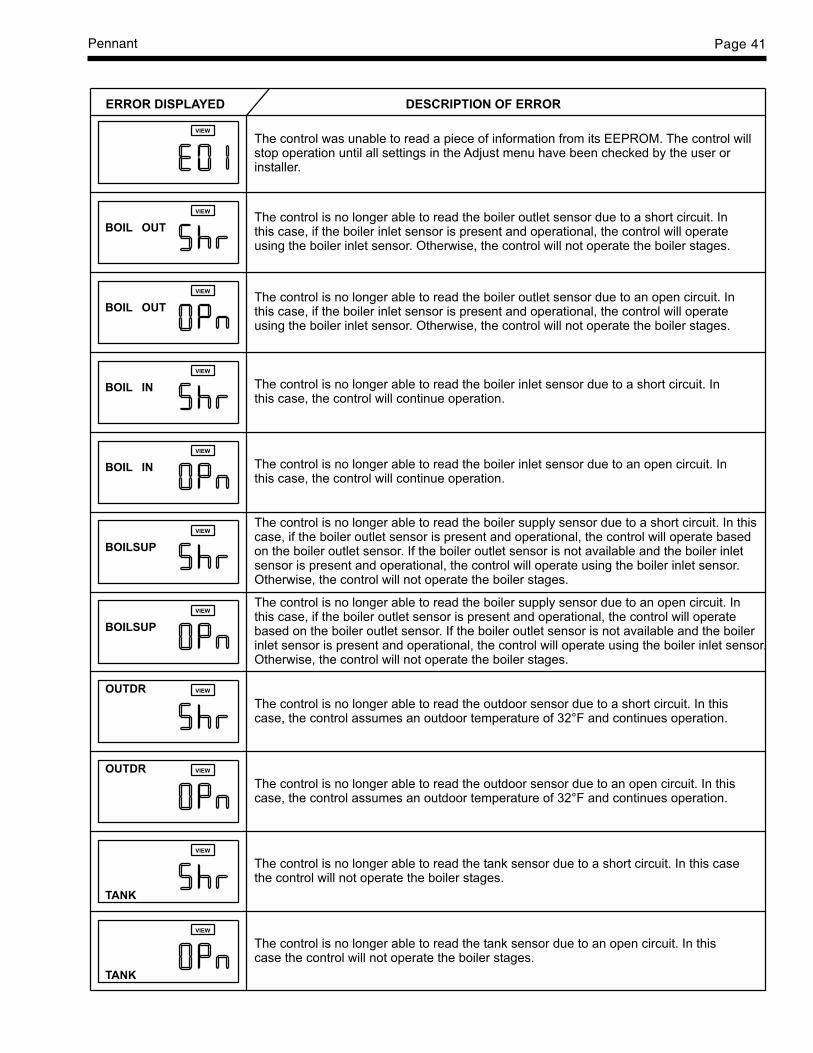
Pennant Page 41
OUTBOIL
BOIL OUT
BOIL IN
BOIL IN
BOILSUP
BOILSUP
OUTDR
OUTDR
TANK
TANK
VIEW
VIEW
VIEW
VIEW
VIEW
VIEW
VIEW
VIEW
VIEW
VIEW
VIEW
ERROR DISPLAYED DESCRIPTION OF ERROR
The control is no longer able to read the boiler supply sensor due to an open circuit. Inthis case, if the boiler outlet sensor is present and operational, the control will operatebased on the boiler outlet sensor. If the boiler outlet sensor is not available and the boilerinlet sensor is present and operational, the control will operate using the boiler inlet sensor.Otherwise, the control will not operate the boiler stages.
The control is no longer able to read the boiler supply sensor due to a short circuit. In thiscase, if the boiler outlet sensor is present and operational, the control will operate basedon the boiler outlet sensor. If the boiler outlet sensor is not available and the boiler inletsensor is present and operational, the control will operate using the boiler inlet sensor.Otherwise, the control will not operate the boiler stages.
The control is no longer able to read the boiler inlet sensor due to an open circuit. Inthis case, the control will continue operation.
The control is no longer able to read the boiler outlet sensor due to an open circuit. Inthis case, if the boiler inlet sensor is present and operational, the control will operateusing the boiler inlet sensor. Otherwise, the control will not operate the boiler stages.
The control was unable to read a piece of information from its EEPROM. The control willstop operation until all settings in the Adjust menu have been checked by the user orinstaller.
The control is no longer able to read the outdoor sensor due to an open circuit. In thiscase, the control assumes an outdoor temperature of 32°F and continues operation.
The control is no longer able to read the tank sensor due to an open circuit. In thiscase the control will not operate the boiler stages.
The control is no longer able to read the tank sensor due to a short circuit. In this casethe control will not operate the boiler stages.
The control is no longer able to read the outdoor sensor due to a short circuit. In thiscase, the control assumes an outdoor temperature of 32°F and continues operation.
The control is no longer able to read the boiler inlet sensor due to a short circuit. Inthis case, the control will continue operation.
The control is no longer able to read the boiler outlet sensor due to a short circuit. Inthis case, if the boiler inlet sensor is present and operational, the control will operateusing the boiler inlet sensor. Otherwise, the control will not operate the boiler stages.

LAARS Heating SystemsPage 42
distribution problem. See Section 6.3 regardingcontroller setup. Contact your Laars representative todiscuss possible remedies.
8.4 Short Cycling — Water HeaterShort cycling will generally occur only in
combination space heating and water heatingapplications when the water heater is operating in thespace-heating mode. Because the Pennant is a stage-fired water heater and its input will reduce when thereis a reduction in heating load, short cycling is greatlyreduced. If the heating load drops below the minimuminput of the water heater for an extended period, thewater heater will have a tendency to short cycle. Ifshort cycling is frequently experienced, regardless ofthe control’s attempt to limit it, the heating loadshould be redistributed to control it. See Section 6.3regarding controller setup.
If short cycling occurs in a water heaterapplication, it is probably caused by undersized pipingbetween the water heater and the storage tank or bysome other factor that restricts proper water flowthrough the water heater. The cause should bedetermined and corrected.
8.5 High Gas ConsumptionAppliances operating with an improper air/fuel
ratio are very inefficient and consequently, have veryhigh gas consumption. Because efficiency is highwhen the CO
2 is high (or O
2 is low), appliances
operating with low CO2 or high O
2 (especially LP
appliances) consume more gas. Adjust the CO2 or O
2for optimum efficiency. If no combustion analyzingequipment (CO
2 or O
2) is available then a proper
adjustment of the air/fuel ratio (CO2 or O
2) cannot be
accomplished. However, by briefly sniffing the fluegases it is possible to determine if the CO
2 or O
2 is
within the proper range. No significant flue gas odorshould be detected when combustion is proper. Astrong piercing smell indicates poor combustion andgenerally a lean mixture - low CO
2 or high O
2 . The
CO2 should be 8% at high fire. To check the CO2, first
verify that the supply gas pressure is within 5" to 13"w.c. (1.2 to 3.2 kPa) With the Pennant running with allstages firing, set the air box pressure to 1.5" w.c. (0.37kPa) (as a starting point), by adjusting the airshutter(s) at the bottom of the fan(s). Check the CO2,and adjust the air shutters if further adjustment to theCO2 is needed. Models 1250 to 2000 have twoblowers and two air chambers (boxes). The pressure ofeach air box must be equal when the final adjustmentis made.
8.6 Troubleshooting the TemperatureControlA trouble shooting chart for the temperature
control is shown on the previous page.
8.7 Troubleshooting Pennant ControlsThe Pennant series consists of two 2-stage
models (500 and 750), one 3-stage model (1000), andfour 4-stage models (1250 to 2000). The 2-stagemodels have one ignition module, and the 3- and 4-stage models have two ignition modules capable ofindependent operation.
A diagnostic panel, that includes test points, aswell as diagnostic lights, is provided in the controlmodule. It is located on the right side of the module,behind the display. To access, remove the retainingscrews from the display cover panel and remove it.Grasp the control module at its base and pull itoutward. Ladder diagrams are shown in Figures 26through 28. Voltage test points on the diagnostic panelare indicated by solid circles connected by shortdiagonal lines.
Figure 26 shows the diagram for the 2-stagemodels 500 and 750. These have one blower and oneignition module. The blower is energized directlythrough the “inducer” terminals F1 and F2 of the(Fenwal) ignition module. The 24V power to the 2nd
stage gas valve is routed through the 1st stage VALVEterminal, so that stage 2 cannot fire unless the stage 1gas valve is open. The 750 differs from the 500 onlyin that the 750 has two gas trains in stage 1, while the500 has only one.
The ladder diagram for the model 1000 is shownin Figure 27. Ignition module #1 handles stages 1 and2, and ignition module #2 handles stage 3. The singleblower is energized directly through the “inducer”terminals of either ignition module. The 24V power tothe T’STAT terminal of both ignition modules isrouted through the safety interlocks.
The ladder diagram for models 1250 to 2000 isshown in Figure 28. These 4-stage models have twoignition modules, each with its own blower, and eachcontrolling 2 stages. The blowers are energized by theignition modules indirectly via switching relays. Wheneither ignition module receives a call for heat, itswitches its blower to high speed and the blower ofthe idle ignition module to low speed.
The wiring schematics for the Pennant 500 –1000 are shown in Figure 29, and the schematics forthe 1250 to 2000 are shown in Figure 30. All 24Vwiring is routed through the diagnostic PC board.
Pennant Page 43
Wiring harnesses connect between the diagnostic PCboard and the control components, indicator board, orfield wiring terminal strip. The diagnostic boardcontains LEDs that indicate open status of the safetyinterlocks, and quick-connect terminals that providetests points for checking voltage/continuity at variouspoints in the control circuit. Line-voltage connectionsare routed via the line-voltage terminal buss.
Certain control elements that may need to be re-wired in the field are connected via the field wiringterminal strip rather than to the diagnostic PC board.These include the low-water cutoff (LWCO), waterflow switch, and inlet/outlet water temperaturesensors.
SECTION 9.Replacement PartsOnly genuine Laars replacement parts should be used.
9.1 General InformationTo order or purchase parts for the Laars Pennant,
contact your nearest Laars dealer or distributor. If theycannot supply you with what you need, contactCustomer Service (see back cover for address,telephone and fax numbers).
9.2 Parts List
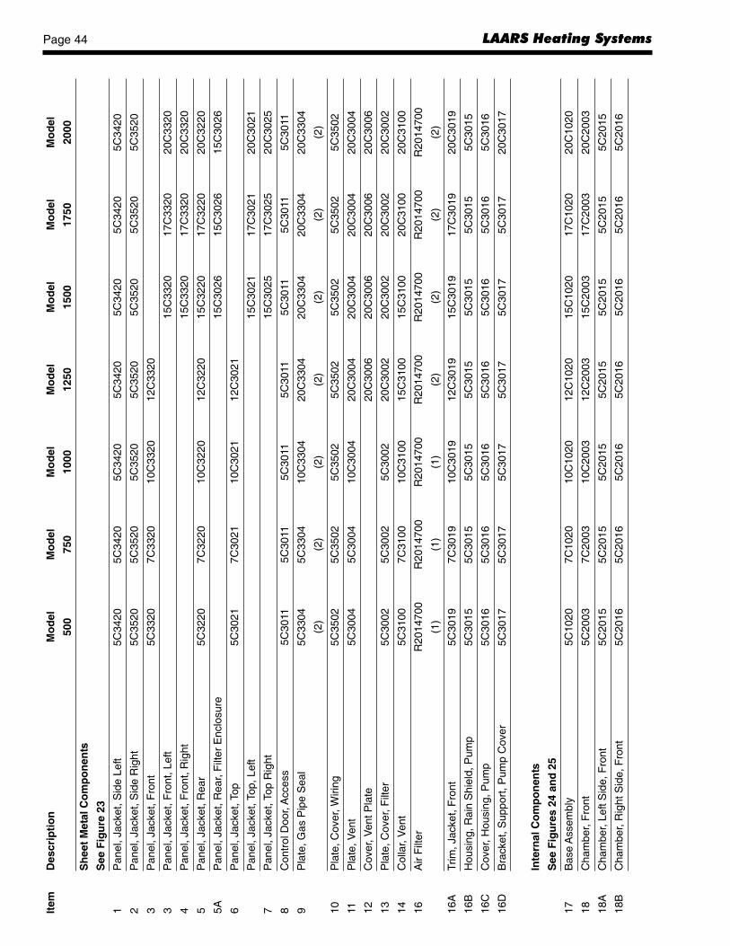
LAARS Heating SystemsPage 44It
emD
escr
ipti
on
Mo
del
Mo
del
Mo
del
Mo
del
Mo
del
Mo
del
Mo
del
500
750
1000
1250
1500
1750
2000
Sh
eet
Met
al C
om
po
nen
ts
See
Fig
ure
23
1P
anel
, Jac
ket,
Sid
e Le
ft5C
3420
5C34
205C
3420
5C34
205C
3420
5C34
205C
3420
2P
anel
, Jac
ket,
Sid
e R
ight
5C35
205C
3520
5C35
205C
3520
5C35
205C
3520
5C35
20
3P
anel
, Jac
ket,
Fro
nt5C
3320
7C33
2010
C33
2012
C33
20
3P
anel
, Jac
ket,
Fro
nt, L
eft
15C
3320
17C
3320
20C
3320
4P
anel
, Jac
ket,
Fro
nt, R
ight
15C
3320
17C
3320
20C
3320
5P
anel
, Jac
ket,
Rea
r5C
3220
7C32
2010
C32
2012
C32
2015
C32
2017
C32
2020
C32
20
5AP
anel
, Jac
ket,
Rea
r, F
ilter
Enc
losu
re15
C30
2615
C30
2615
C30
26
6P
anel
, Jac
ket,
Top
5C30
217C
3021
10C
3021
12C
3021
Pan
el, J
acke
t, To
p, L
eft
15C
3021
17C
3021
20C
3021
7P
anel
, Jac
ket,
Top
Rig
ht15
C30
2517
C30
2520
C30
25
8C
ontr
ol D
oor,
Acc
ess
5C30
115C
3011
5C30
115C
3011
5C30
115C
3011
5C30
11
9P
late
, Gas
Pip
e S
eal
5C33
045C
3304
10C
3304
20C
3304
20C
3304
20C
3304
20C
3304
(2)
(2)
(2)
(2)
(2)
(2)
(2)
10P
late
, Cov
er, W
iring
5C35
025C
3502
5C35
025C
3502
5C35
025C
3502
5C35
02
11P
late
, Ven
t5C
3004
5C30
0410
C30
0420
C30
0420
C30
0420
C30
0420
C30
04
12C
over
, Ven
t Pla
te20
C30
0620
C30
0620
C30
0620
C30
06
13P
late
, Cov
er, F
ilter
5C30
025C
3002
5C30
0220
C30
0220
C30
0220
C30
0220
C30
02
14C
olla
r, V
ent
5C31
007C
3100
10C
3100
15C
3100
15C
3100
20C
3100
20C
3100
16A
ir F
ilter
R20
1470
0R
2014
700
R20
1470
0R
2014
700
R20
1470
0R
2014
700
R20
1470
0
(1)
(1)
(1)
(2)
(2)
(2)
(2)
16A
Trim
, Jac
ket,
Fro
nt5C
3019
7C30
1910
C30
1912
C30
1915
C30
1917
C30
1920
C30
19
16B
Hou
sing
, Rai
n S
hiel
d, P
ump
5C30
155C
3015
5C30
155C
3015
5C30
155C
3015
5C30
15
16C
Cov
er, H
ousi
ng, P
ump
5C30
165C
3016
5C30
165C
3016
5C30
165C
3016
5C30
16
16D
Bra
cket
, Sup
port
, Pum
p C
over
5C30
175C
3017
5C30
175C
3017
5C30
175C
3017
20C
3017
Inte
rnal
Co
mp
on
ents
See
Fig
ure
s 24
an
d 2
5
17B
ase
Ass
embl
y5C
1020
7C10
2010
C10
2012
C10
2015
C10
2017
C10
2020
C10
20
18C
ham
ber,
Fro
nt5C
2003
7C20
0310
C20
0312
C20
0315
C20
0317
C20
0320
C20
03
18A
Cha
mbe
r, Le
ft S
ide,
Fro
nt5C
2015
5C20
155C
2015
5C20
155C
2015
5C20
155C
2015
18B
Cha
mbe
r, R
ight
Sid
e, F
ront
5C20
165C
2016
5C20
165C
2016
5C20
165C
2016
5C20
16

Pennant Page 45
Item
Des
crip
tio
nM
od
elM
od
elM
od
elM
od
elM
od
elM
od
elM
od
el
500
750
1000
1250
1500
1750
2000
19C
ham
ber,
Rea
r5C
2006
7C20
0610
C20
0612
C20
0615
C20
0617
C20
0620
C20
06
20C
ham
ber A
ssem
bly,
Lef
t, B
otto
m5C
2600
5C26
005C
2600
5C26
005C
2600
5C26
005C
2600
21C
ham
ber A
ssem
bly,
Rig
ht, B
otto
m5C
2200
5C22
005C
2200
5C22
005C
2200
5C22
005C
2200
22C
ham
ber,
Top
5C20
017C
2001
10C
2001
12C
2001
15C
2001
17C
2001
20C
2001
23C
ham
ber,
Sid
e, T
op5C
2002
5C20
025C
2002
5C20
025C
2002
5C20
025C
2002
24E
xhau
st P
lenu
m5C
2007
10C
2007
10C
2007
20C
2007
20C
2007
20C
2007
20C
2007
25B
rack
et, C
ham
ber,
Fro
nt5C
2009
7C20
0910
C20
09
Bra
cket
, Cha
mbe
r, F
ront
Lef
t12
C20
1115
C20
1117
C20
1120
C20
11
26B
rack
et, C
ham
ber,
Fro
nt R
ight
12C
2009
15C
2009
17C
2009
20C
2009
27D
ivid
er, C
ham
ber,
Fro
nt15
C20
1020
C20
02
27A
Div
ider
, Upp
er, C
ham
ber,
Fro
nt15
C20
0515
C20
05
27B
Div
ider
, Low
er, C
ham
ber,
Fro
nt15
C20
0215
C20
02
28C
over
, Cha
mbe
r5C
2004
7C20
04
Cov
er, C
ham
ber,
Fro
nt L
eft
10C
2004
12C
2010
15C
2004
17C
2010
20C
2010
29D
oor,
Cha
mbe
r Acc
ess
5C20
055C
2005
5C20
055C
2005
5C20
055C
2005
5C20
05
(1)
(1)
(1)
(2)
(2)
(2)
(2)
30C
over
, Cha
mbe
r, F
ront
Rig
ht10
C20
1012
C20
0815
C20
0417
C20
0820
C20
08
Gas
ket,
Tape
,Rr,
Bas
e (4
3')
R00
1450
0R
0014
500
R00
1450
0R
0014
500
R00
1450
0R
0014
500
R00
1450
0
Gas
ket,
Tape
, Ft A
ir C
ham
ber
(63'
)R
0014
600
R00
1460
0R
0014
600
R00
1460
0R
0014
600
R00
1460
0R
0014
600
32Ig
nito
r, H
ot S
urfa
ce, w
ith G
aske
t24
00-2
8624
00-2
8624
00-2
8624
00-2
8624
00-2
8624
00-2
8624
00-2
86
(1)
(1)
(2)
(2)
(2)
(2)
(2)
33Ti
le, S
ide
(Rig
ht a
nd L
eft)
T20
1560
0T
2015
600
T20
1560
0T
2015
600
T20
1560
0T
2015
600
T20
1560
0
(2)
(2)
(2)
(2)
(2)
(2)
(2)
34Ti
le, F
ront
T20
1730
0
(1)
35Ti
le, F
ront
, Lef
t Sid
eT
2016
200
T20
1680
0T
2016
800
T20
1680
0T
2016
800
T20
1680
0
(1)
(1)
(1)
(1)
(1)
(1)
35A
Tile
, Fro
nt, R
ight
Sid
eT
2016
300
T20
1710
0T
2017
900
T20
1710
0T
2017
900
T20
1710
0
(1)
(1)
(1)
(1)
(1)
(1)
35B
Tile
, Fro
nt, C
ente
rT
2016
900
T20
1690
0T
2016
900
T20
1690
0
(1)
(1)
(2)
(2)
36Ti
le, R
ear
T20
1570
0
(1)
37Ti
le, R
ear,
Left
Sid
eT
2017
500
T20
1660
0T
2016
600
T20
1660
0T
2016
600
T20
1660
0
(1)
(1)
(1)
(1)
(1)
(1)

LAARS Heating SystemsPage 46It
emD
escr
ipti
on
Mo
del
Mo
del
Mo
del
Mo
del
Mo
del
Mo
del
Mo
del
500
750
1000
1250
1500
1750
2000
37A
Tile
, Rea
r, R
ight
Sid
eT
2016
600
T20
1660
0T
2018
100
T20
1660
0T
2018
100
T20
1660
0
(1)
(1)
(1)
(1)
(1)
(1)
37B
Tile
, Rea
r, C
ente
rT
2017
200
T20
1720
0T
2017
200
T20
1720
0
(1)
(1)
(2)
(2)
38Ti
le, B
otto
mT
2015
500
(1)
39Ti
le, B
otto
m, L
eft S
ide
T20
1740
0T
2017
400
T20
1740
0T
2017
400
T20
1740
0T
2017
400
(1)
(1)
(1)
(1)
(1)
(1)
39A
Tile
, Bot
tom
, Rig
ht S
ide
T20
1650
0T
2017
400
T20
1800
0T
2017
400
T20
1800
0T
2017
400
(1)
(1)
(1)
(1)
(1)
(1)
39B
Tile
, Bot
tom
, Cen
ter
T20
1590
0T
2015
900
T20
1590
0T
2015
900
(1)
(1)
(2)
(2)
41H
eat E
xcha
nger
, Cop
per
R20
1490
1R
2014
902
R20
1490
3R
2026
701
R20
1490
4R
2026
702
R20
1490
5
Hea
t Exc
hang
er, C
upro
-Nic
kel
R20
2780
1R
2027
802
R20
2780
3R
2027
804
R20
2780
5R
2027
806
R20
2780
7
42W
ater
Bar
rier,
Inle
t/out
let
2023
0101
2023
0101
2023
0101
2023
0101
2023
0101
2023
0101
2023
0101
43W
ater
Bar
rier,
Inle
t10
3383
0010
3383
0010
3383
0010
3383
0010
3383
0010
3383
0010
3383
00
44G
aske
t, H
eade
rS
0095
100
S00
9510
0S
0095
100
S00
9510
0S
0095
100
S00
9510
0S
0095
100
(2)
(2)
(2)
(2)
(2)
(2)
(2)
45C
over
, In/
Out
, Gla
ss-L
ined
Cas
t Iro
n10
3645
0410
3645
0410
3645
0410
3645
0410
3645
0410
3645
0410
3645
04
Cov
er, I
n/O
ut, B
ronz
e10
3645
0110
3645
0110
3645
0110
3645
0110
3645
0110
3645
0110
3645
01
46W
ell,
Tem
pera
ture
Con
trol
RE
2058
300
RE
2058
300
RE
2058
300
RE
2058
300
RE
2058
300
RE
2058
300
RE
2058
300
47G
aske
t, F
lang
eS
0063
700
S00
6370
0S
0063
700
S00
6370
0S
0063
700
S00
6370
0S
0063
700
(2)
(2)
(2)
(2)
(2)
(2)
(2)
48F
lang
e, C
ast I
ron
1039
1302
1039
1302
1039
1302
1039
1302
1039
1302
1039
1302
1039
1302
Fla
nge,
Bro
nze
2025
5401
2025
5401
2025
5401
2025
5401
2025
5401
2025
5401
2025
5401
49R
elie
f Val
ve, P
NC
H, 7
5 P
SI
A00
6330
0A
0063
300
A00
6360
0A
0063
600
A00
6360
0A
0063
600
A00
0270
0
Rel
ief V
alve
, PN
CV,
125
PS
IR
A00
0120
0R
A00
0120
0R
A00
0120
0R
A00
0120
0A
0064
400
A00
6440
0A
0066
400
50Te
e, A
dapt
er, O
utle
t, C
ast I
ron
2013
0001
2013
0001
2013
0001
2013
0002
2013
0002
2013
0002
2013
0002
Tee,
Ada
pter
, Out
let,
Bro
nze
2015
0301
2015
0301
2015
0301
2015
0301
2015
0301
2015
0301
2015
0303
51F
low
Sw
itch
RE
0013
000
RE
0013
000
RE
0013
000
RE
0013
000
RE
0013
000
RE
0013
000
RE
0013
000
52G
auge
, Tem
pera
ture
/Pre
ssur
eR
A00
7900
0R
A00
7900
0R
A00
7900
0R
A00
7900
0R
A00
7900
0R
A00
7900
0R
A00
7900
0
54Lo
w W
ater
Cut
off
E20
7590
0E
2075
900
E20
7590
0E
2075
900
E20
7590
0E
2075
900
E20
7590
0
55P
ump
Hou
sing
, Gla
ss-li
ned,
Cas
t Iro
nR
1026
1501
R10
2615
01R
1026
1501
R10
2615
01R
1026
1501
R10
2615
01R
1026
1501
Pum
p H
ousi
ng, B
ronz
e10
4833
0010
4833
0010
4833
0010
4833
0010
4833
0010
4833
0010
4833
00

Pennant Page 47
Item
Des
crip
tio
nM
od
elM
od
elM
od
elM
od
elM
od
elM
od
elM
od
el
500
750
1000
1250
1500
1750
2000
56G
aske
t, P
ump
Ada
pter
S00
2460
0S
0024
600
S00
2460
0S
0024
600
S00
2460
0S
0024
600
S00
2460
0
57P
ump
Ada
pter
, Gla
ss-li
ned
Cas
t Iro
n10
3642
0010
3642
0010
3642
0010
3642
0010
3642
0010
3642
0010
3642
00
Pum
p A
dapt
er, B
ronz
e10
3642
0110
3642
0110
3642
0110
3642
0110
3642
0110
3642
0110
3642
01
58B
affle
, Diff
user
, Pum
p In
let
1033
8400
1033
8400
1033
8400
1033
8400
1033
8400
1033
8400
1033
8400
59P
ress
ure
Sw
itch
RE
0240
900
RE
0240
900
RE
0240
900
RE
0240
900
RE
0240
900
RE
0240
900
RE
0240
900
(2)
(2)
(2)
(3)
(3)
(3)
(3)
60B
low
erA
2108
900
A21
0890
0A
2108
900
A21
0890
0A
2108
900
A21
0890
0A
2108
900
(1)
(1)
(1)
(2)
(2)
(2)
(2)
61W
eldm
ent,
Blo
wer
Mou
nt5C
5300
5C53
005C
5300
5C53
005C
5300
5C53
005C
5300
(1)
(1)
(1)
(2)
(2)
(2)
(2)
62D
ampe
r, D
uct A
ssem
bly,
Blo
wer
15C
5400
15C
5400
15C
5400
15C
5400
(2)
(2)
(2)
(2)
Ele
ctri
cal C
om
po
nen
ts
See
Fig
ure
25
63C
ontr
ol P
anel
Wel
dmen
t5C
7200
5C72
005C
7200
5C72
005C
7200
5C72
005C
7200
64B
rack
et, C
ontr
ol P
anel
Mou
ntin
g5C
7103
5C71
035C
7103
5C71
035C
7103
5C71
035C
7103
65Te
rmin
al B
oard
, Fie
ld W
iring
E23
0740
0E
2307
401
E23
0740
2E
2307
403
E23
0740
4E
2307
405
E23
0740
6
66Ig
nitio
n C
ontr
ol, S
ingl
e Tr
ial
E21
0730
0E
2107
300
E21
0730
0E
2107
300
E21
0730
0E
2107
300
E21
0730
0
(1)
(1)
(2)
(2)
(2)
(2)
(2)
Igni
ltion
Con
trol
, Thr
ee T
rial
E23
1390
0E
2313
900
E23
1390
0E
2313
900
E23
1390
0E
2313
900
E23
1390
0
(1)
(1)
(2)
(2)
(2)
(2)
(2)
67D
iagn
ostic
Boa
rdE
2105
500
E21
0550
0E
2105
500
E21
0550
0E
2105
500
E21
0550
0E
2105
500
68In
dica
tor
Ligh
t Pan
el B
oard
E21
0560
0E
2105
600
E21
0560
0E
2105
600
E21
0560
0E
2105
600
E21
0560
0
69Te
mpe
ratu
re C
ontr
olE
2106
900
E21
0690
0E
2106
800
E21
0680
0E
2106
800
E21
0680
0E
2106
800
70H
igh
Lim
it, A
uto
Res
et, P
NC
HR
E00
1440
0R
E00
1440
0R
E00
1440
0R
E00
1440
0R
E00
1440
0R
E00
1440
0R
E00
1440
0
Hig
h Li
mit,
Aut
o R
eset
, PN
CV,
210
F M
ax.
E22
1770
0E
2217
700
E22
1770
0E
2217
700
E22
1770
0E
2217
700
E22
1770
0
71H
igh
Lim
it, M
anua
l Res
et, P
NC
HE
0015
900
E00
1590
0E
0015
900
E00
1590
0E
0015
900
E00
1590
0E
0015
900
Hig
h Li
mit,
Man
ual R
eset
, PN
CV,
210
F M
ax.
E22
1780
0E
2217
800
E22
1780
0E
2217
800
E22
1780
0E
2217
800
E22
1780
0
72R
elay
, Pum
p (S
PS
T)
E00
9830
0E
0098
300
E00
9830
0E
0098
300
E00
9830
0E
0098
300
E00
9830
0
Rel
ay, F
an (
DP
DT
)E
0076
600
E00
7660
0E
0076
600
E00
7660
0
(2)
(2)
(2)
(2)
73Te
rmin
al B
us (
12 P
ositi
on)
E23
1070
0E
2310
700
E23
1070
0E
2310
700
E23
1070
0E
2310
700
E23
1070
0
74Tr
ansf
orm
erE
2310
400
E23
1040
0E
2310
400
E23
1280
0E
2312
800
E23
1280
0E
2312
800
(2)
(2)
(2)
(2)
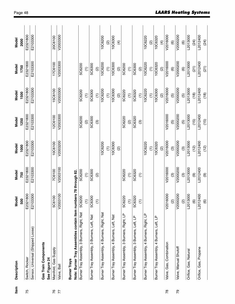
LAARS Heating SystemsPage 48It
emD
escr
ipti
on
Mo
del
Mo
del
Mo
del
Mo
del
Mo
del
Mo
del
Mo
del
500
750
1000
1250
1500
1750
2000
75S
witc
h, R
ocke
rE
2321
800
E23
2180
0E
2321
800
E23
2180
0E
2321
800
E23
2180
0E
2321
800
Sen
sor,
Uni
vers
al (
Shi
pped
Loo
se)
E21
0330
0E
2103
300
E21
0330
0E
2103
300
E21
0330
0E
2103
300
E21
0330
0
Gas
Tra
in C
om
po
nen
ts
See
Fig
ure
24
76M
anifo
ld, G
as S
uppl
y5C
6100
7C61
0010
C61
0012
C61
0015
C61
0017
C61
0020
C61
00
77V
alve
, Bal
lV
2003
100
V20
0310
0V
2003
200
V20
0330
0V
2003
300
V20
0330
0V
2003
300
Bu
rner
Tra
ys
No
te:
Bu
rner
Tra
y A
ssem
blie
s co
nta
in it
em n
um
ber
s 78
th
rou
gh
82.
Bur
ner
Tray
Ass
embl
y, 3
Bur
ners
, Rig
ht, N
at5C
6200
5C62
005C
6200
5C62
005C
6200
(1)
(1)
(2)
(1)
(1)
Bur
ner
Tray
Ass
embl
y, 3
Bur
ners
, Lef
t, N
at5C
6300
5C63
005C
6300
5C63
005C
6300
(1)
(2)
(3)
(1)
(2)
Bur
ner
Tray
Ass
embl
y, 4
Bur
ners
, Rig
ht, N
at10
C62
0010
C62
0010
C62
0010
C62
00
(1)
(1)
(1)
(2)
Bur
ner
Tray
Ass
embl
y, 4
Bur
ners
, Lef
t, N
at10
C63
0010
C63
0010
C63
0010
C63
00
(2)
(2)
(2)
(4)
Bur
ner
Tray
Ass
embl
y, 3
Bur
ners
, Rig
ht, L
P5C
6220
5C62
205C
6220
5C62
205C
6200
(1)
(1)
(2)
(1)
(1)
Bur
ner
Tray
Ass
embl
y, 3
Bur
ners
, Lef
t, LP
5C63
205C
6320
5C63
205C
6320
5C63
00
(1)
(1)
(3)
(1)
(2)
Bur
ner
Tray
Ass
embl
y, 4
Bur
ners
, Rig
ht, L
P10
C62
2010
C62
2010
C62
2010
C62
20
(1)
(1)
(1)
(2)
Bur
ner
Tray
Ass
embl
y, 4
Bur
ners
, Lef
t, LP
10C
6320
10C
6300
10C
6320
10C
6320
(2)
(2)
(2)
(4)
78V
alve
, Gas
, Com
bina
tion
V20
1600
0V
2016
000
V20
1600
0V
2016
000
V20
1600
0V
2016
000
V20
1600
0
(2)
(3)
(3)
(5)
(5)
(6)
(6)
79V
alve
, Man
ual S
huto
ffV
2000
200
V20
0020
0V
2000
200
V20
0020
0V
2000
200
V20
0020
0V
2000
200
(2)
(3)
(3)
(5)
(5)
(6)
(6)
Orif
ice,
Gas
, Nat
ural
L201
3000
L201
3000
L201
3000
L201
3000
L201
3000
L201
3000
L201
3000
(6)
(9)
(12)
(15)
(18)
(21)
(24)
Orif
ice,
Gas
, Pro
pane
L201
2400
L201
2400
L201
2400
L201
2400
L201
2400
L201
2400
L201
2400
(6)
(9)
(12)
(15)
(18)
(21)
(24)

Pennant Page 49
Item
Des
crip
tio
nM
od
elM
od
elM
od
elM
od
elM
od
elM
od
elM
od
el
500
750
1000
1250
1500
1750
2000
80B
urne
r Tr
ay M
anifo
ld, 3
Bur
ners
, Rig
htL2
0129
00L2
0129
00L2
0129
00L2
0129
00L2
0129
00
(1)
(1)
(2)
(1)
(1)
Bur
ner
Tray
Man
ifold
, 3 B
urne
rs, L
eft
L201
2800
L201
2800
L201
2800
L201
2800
L201
2800
(1)
(1)
(3)
(1)
(2)
Bur
ner
Tray
Man
ifold
, 4 B
urne
rs, R
ight
L201
2700
L201
2700
L201
2700
L201
2700
(1)
(1)
(1)
(2)
Bur
ner
Tray
Man
ifold
, 4 B
urne
rs, L
eft
L201
2600
L201
2600
L201
2600
L201
2600
(2)
(2)
(2)
(4)
81B
urne
r Tr
ay, 3
Bur
ners
L201
2200
L201
2200
L201
2200
L201
2200
(2)
(3)
(5)
(2)
(3)
Bur
ner
Tray
, 4 B
urne
rsL2
0125
00L2
0125
00L2
0125
00L2
0125
00
(3)
(3)
(3)
(5)
82G
aske
t, B
urne
r Tr
ay, 3
Bur
ner
S20
1270
0S
2012
700
S20
1270
0S
2012
700
S20
1270
0
(2)
(3)
(5)
(2)
(3)
Gas
ket,
Bur
ner
Tray
, 4 B
urne
rS
2012
500
S20
1250
0S
2012
500
S20
1250
0
(3)
(3)
(3)
(6)
Gas
ket T
ape,
Rr,
Bas
e (4
3')
R20
1450
0R
2014
500
R20
1450
0R
2014
500
R20
1450
0R
2014
500
R20
1450
0
Gas
ket T
ape,
Ft A
ir C
ham
ber
(63'
)R
2014
600
R20
1460
0R
2014
600
R20
1460
0R
2014
600
R20
1460
0R
2014
600
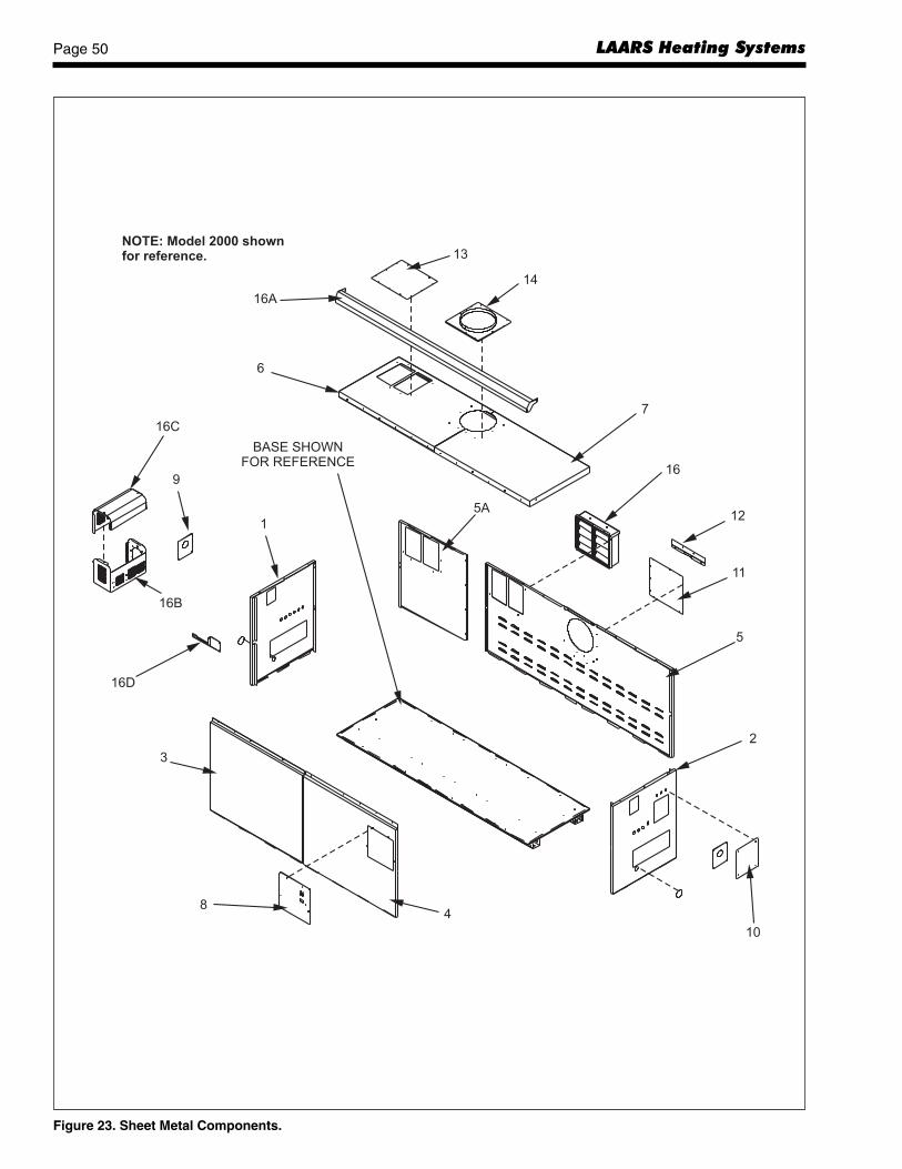
LAARS Heating SystemsPage 50
Figure 23. Sheet Metal Components.
1
2
3
4
5
6
7
8
9
10
11
12
13
14
16
16B
16C
16D
16A
BASE SHOWNFOR REFERENCE
NOTE: Model 2000 shownfor reference.
5A

Pennant Page 51
Figure 24. Internal Components.
17
19
18A
20
21
22
24
23
25
26
27/A/B
28
30
29
77
76
78
80
79
81
82
32
34/35
33
36/37
37B
35B
38/39
39A
41
60
61
62
59
ASee enlargement
on next page
39B
37A
33
35A
18
18B
NOTE: Model 2000 shownfor reference.

LAARS Heating SystemsPage 52
Figure 25. Heat Exchanger Components.
A
See pump chart belowfor pump numbers.
Pennant Hydronic
Model Pump P/N500 A2001700750 A2001700
1000 A20018001250 A20018001500 A20019001750 A20019002000 A2109700
Pennant Water Heater
Model Pump P/NSoft Water Normal Water Hard Water
500 A2001700 A2001700 A2001900750 A2001700 A2001700 A2001900
1000 A2001700 A2001800 A20019001250 A2001700 A2001800 A20019001500 A2001700 A2001900 A20019001750 A2001900 A2001900 A20019002000 A2109700 A2109700 A2109700
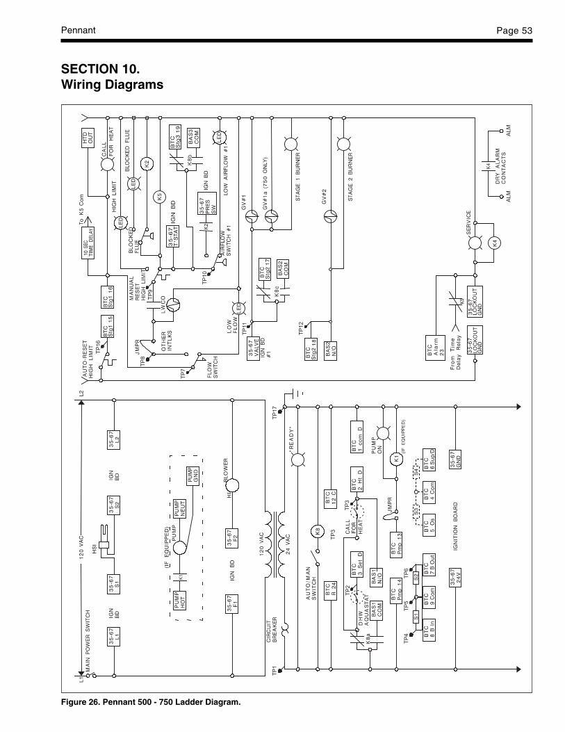
Pennant Page 53
Figure 26. Pennant 500 - 750 Ladder Diagram.
SECTION 10.Wiring Diagrams
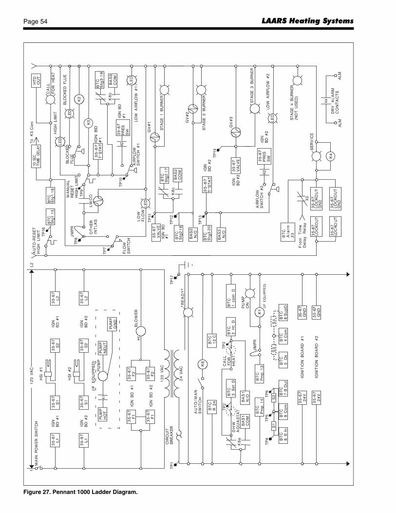
LAARS Heating SystemsPage 54
Figure 27. Pennant 1000 Ladder Diagram.
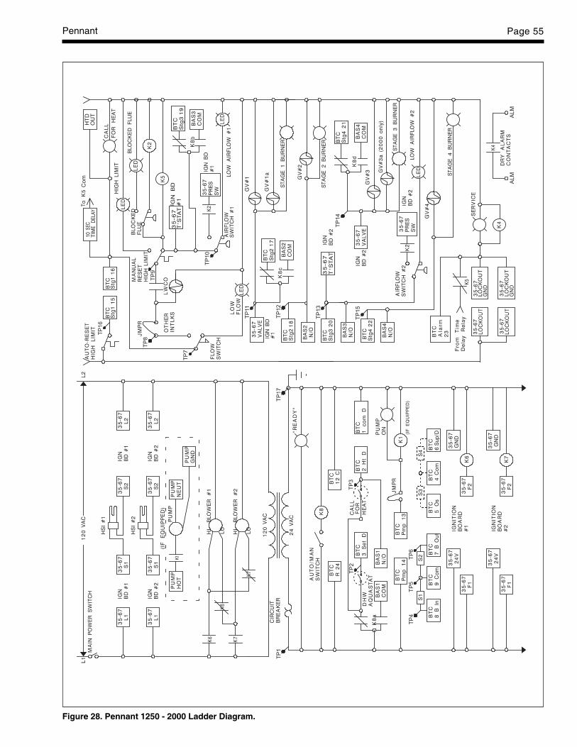
Pennant Page 55
Figure 28. Pennant 1250 - 2000 Ladder Diagram.

LAARS Heating SystemsPage 56
Figure 29. Pennant 500 - 1000 Wiring Schematic.
Not
e: P
ositi
ons
of fi
eld
wiri
ng te
rmin
als
may
var
y, b
utte
rmin
al d
esig
natio
ns a
re a
s in
dica
ted.
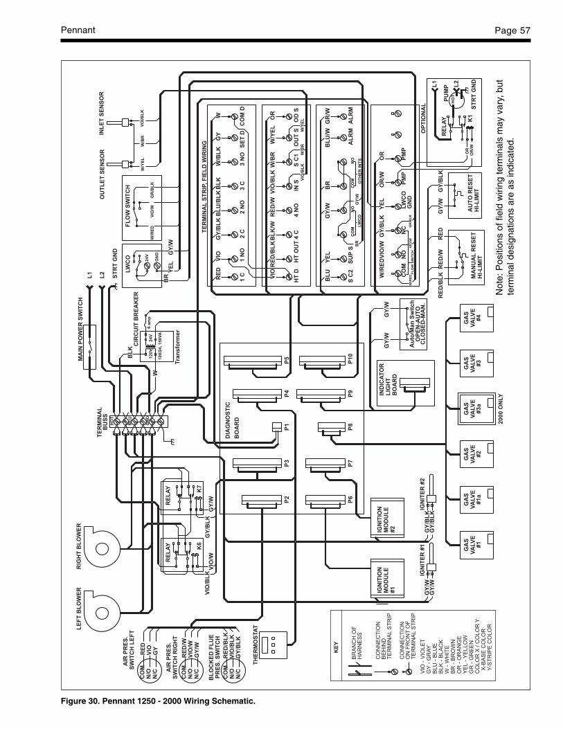
Pennant Page 57
Figure 30. Pennant 1250 - 2000 Wiring Schematic.
Not
e: P
ositi
ons
of fi
eld
wiri
ng te
rmin
als
may
var
y, b
utte
rmin
al d
esig
natio
ns a
re a
s in
dica
ted.

LAARS Heating SystemsPage 58
Figure 31 . Field Wiring.
Not
e: P
ositi
ons
of fi
eld
wiri
ng te
rmin
als
may
var
y, b
utte
rmin
al d
esig
natio
ns a
re a
s in
dica
ted.
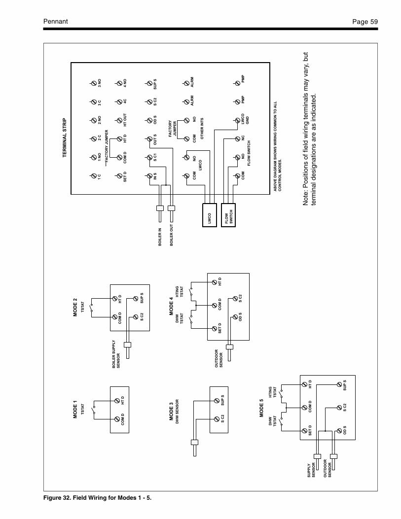
Pennant Page 59
TS
TA
TT
STA
T
-- --
--
--
--
-- --
1C
1N
O2
C2
NO
3C
3N
O
SE
TD
CO
MD
HT
DH
TO
UT
4C
4N
O
INS
SC
1O
UT
SO
DS
SC
2S
UP
S
CO
MN
ON
OC
OM
AL
RM
AL
RM
CO
MN
ON
CLW
CO
GN
D
PM
PP
MP
LW
CO
OT
HE
RIN
TS
FL
OW
SW
ITC
H
TE
RM
INA
LS
TR
IP
MO
DE
1M
OD
E2
MO
DE
3M
OD
E4
MO
DE
5
CO
MD
HT
DC
OM
DH
TD
CO
MD
HT
DS
ET
D
CO
MD
HT
DS
ET
D
SC
2S
UP
S
BO
ILE
RIN
BO
ILE
RO
UT
LW
CO
FL
OW
SW
ITC
H
AB
OV
ED
IAG
RA
MS
HO
WS
WIR
ING
CO
MM
ON
TO
AL
L
CO
NT
RO
LM
OD
ES
.
SC
2S
UP
S
OD
SS
C2
DH
W
TS
TA
T
HT
ING
TS
TA
T
OU
TD
OO
R
SE
NS
OR
BO
ILE
RS
UP
PLY
SE
NS
OR
DH
WS
EN
SO
R
DH
W
TS
TA
T
HT
ING
TS
TA
T
OD
SS
C2
SU
PS
SU
PP
LY
SE
NS
OR
OU
TD
OO
R
SE
NS
OR
FA
CT
OR
Y
JU
MP
ER
***F
AC
TO
RY
JU
MP
ER
Figure 32. Field Wiring for Modes 1 - 5.
Not
e: P
ositi
ons
of fi
eld
wiri
ng te
rmin
als
may
var
y, b
utte
rmin
al d
esig
natio
ns a
re a
s in
dica
ted.

H22
1440
0B
20 Industrial Way, Rochester, NH 03867 • 603.335.6300 • FAX 603.335.3355480 S. Service Road West, Oakville, Ontario, Canada L6K 2H4 • 905.844.8233 • FAX 905.844.2635www.laars.com Litho in U.S.A. © Laars Heating Systems 0506 Document 1176B
®
Figure 33. Field Wiring for Mode 6.
1C
1N
O
2C
2N
O
3C
3N
O
4C
4N
O4C
3C
4N
O
3N
O
2C1C
2N
O
1N
O
4sta
ge
bo
iler
usin
g4
co
ntr
olo
utp
uts
4sta
ge
bo
iler
usin
g2
co
ntr
olo
utp
uts
Jum
per
Jum
per
4C
3C
4N
O
3N
O
2C1C
2N
O
1N
O
4sta
ge
bo
iler
usin
g3
co
ntr
olo
utp
uts
Jum
per
Jum
per
4C
3C
4N
O
3N
O
4sta
ge
bo
iler
usin
g1
co
ntr
olo
utp
ut
Jum
per
2C1C
2N
O
1N
O
Jum
per
4sta
ge
3sta
ge
2sta
ge
1sta
ge
3sta
ge
bo
iler
usin
g3
co
ntr
olo
utp
uts
1C
2C
3C
3N
O
2sta
ge
3sta
ge
3N
O3C
1sta
ge
3N
O
Jum
per
3C
3sta
ge
bo
iler
usin
g1
co
ntr
olo
utp
ut
1N
O
2N
O
3sta
ge
bo
iler
usin
g2
co
ntr
olo
utp
uts
Ju
mp
er
2N
O
1N
O
2C1C
2N
O
1N
O
Ju
mp
er
2C1C
Pen
nan
t1250,1500,1750
&2000
(4-S
tag
eB
oiler)
2C1C
1sta
ge
Jum
per
2C
2N
O
2sta
ge
1N
O1C
2N
O
1N
O
2sta
ge
bo
iler
usin
g1
co
ntr
olo
utp
ut
2sta
ge
bo
iler
usin
g2
co
ntr
olo
utp
uts
Pen
nan
t1000
(3-S
tag
eB
oiler)
Pen
nan
t750
&500
(2-S
tag
eB
oiler)
Impro
per
field
wirin
gm
ay
result
infire
or
explo
sio
nw
hic
hcan
cause
pro
pert
ydam
age,severe
inju
ry,or
death
.M
ake
only
wirin
gconnections
whic
hare
inaccord
ance
with
the
Insta
llation
and
Opera
tion
manual.
AV
ER
TIS
SE
ME
NT
Un
câbla
ge
incorr
ectlo
rsde
l’insta
llation
peutcauser
un
incendie
ou
une
explo
sio
npouvantentr
aîn
er
des
dom
mages
maté
riels
,de
gra
ves
ble
ssure
sou
lam
ort
.N
efa
ire
seule
ment
que
les
connexio
ns
confo
rmes
au
Manuel
d’in
sta
llation
et
d’e
xplo
itation.
Th
en
um
ber
of
op
era
tio
nalsta
ges
req
uir
es
that
the
exte
rnalco
ntr
olre
lay
co
nta
cts
be
wir
ed
exactl
yas
sh
ow
n.
Do
no
talt
er
wir
ing
.
WA
RN
ING


![Caliper Operation Instructions[1]](https://static.fdocuments.in/doc/165x107/577cc5701a28aba7119c6424/caliper-operation-instructions1.jpg)


