Microsoft Power Point Presentacio Convencin Profesores De Comercio Es2

INSTALLATION AND OPERATION INSTRUCTIONS EN
Askoll ENERGY SAVING ES2
ES2 ADAPT ES2 SOLAR
ES2 PURE

ENERGY SAVING
2 Declaration of conformity
1 Declaration of conformity
We Askoll Sei S.r.l. declare under our sole responsibility that the family of products Askoll ENERGY SAVING to which this declaration relates are in conformity with the Council Directives on the approximations of the laws of the EC Member State relating to:
EMC Directive (2004/108/EC) Standard used: EN 61000-3-2:2006, EN 61000-3-3:2013, EN 55014-1:2006, EN 55014-2:1997 (including amendments)
LVD Directive (2006/95/EC) Standard used: EN 62233:2008, EN 60335-1:2012, EN 60335-2-51:2003 (including amendments)
ErP Directive (2009/125/EC) Commission Regulations n. 641/2009 and n. 622/2012 Applies only to circulators marked with the energy efficiency index EEI. See the pump nameplate. Standard used: EN16297-1:2012 and EN16297-2:2012
RoHS II Directive (2011/65/EU)
Person authorized to compile technical file and empowered to sign the EC declaration of
Conformity.

3
2 Contents
1 Declaration of conformity ......................................................................................................... 2
2 Contents .................................................................................................................................. 3
3 Indication of instructions .......................................................................................................... 5
4 Important safety and installation instructions ............................................................................ 6
5 Field of application ................................................................................................................... 9
5.1 Types of system ................................................................................................................ 9
5.2 Pumped liquids ................................................................................................................. 9
6 Product information ................................................................................................................ 10
6.1 Description of the product ............................................................................................... 10
6.2 Type key ......................................................................................................................... 10
6.3 Name plate ..................................................................................................................... 11
6.4 Components ................................................................................................................... 11
6.5 Supply............................................................................................................................. 11
6.6 Technical data ................................................................................................................ 12
7 Installation at Site .................................................................................................................. 14
7.1 Installation ...................................................................................................................... 14
7.2 Permissible installation positions..................................................................................... 15
7.3 Motor housing regulation................................................................................................. 15
7.4 Insulation of pump housing ............................................................................................. 16
8 Electric connection ................................................................................................................. 17
9 Commissioning ...................................................................................................................... 18
9.1 Start-up of the circulator .................................................................................................. 18
9.2 Operating elements......................................................................................................... 18
9.3 Mode of operation ........................................................................................................... 19
9.4 Automatic detection of the presence of air - Vent system. ............................................... 20
10 Circulator setting ................................................................................................................ 21
11 Performance curves ........................................................................................................... 22
11.1 Performance curves - ES2 60 ......................................................................................... 22
11.2 Performance curves - ES2 70 ......................................................................................... 22
11.3 Performance curves - ES2 C 60...................................................................................... 23
11.4 Performance curves - ES2 C 70...................................................................................... 23
11.5 Performance curves - ES2 ADAPT 60 ............................................................................ 24
11.6 Performance curves - ES2 ADAPT 70 ............................................................................ 24
11.7 Performance curves - ES2 SOLAR 60 ............................................................................ 25
11.8 Performance curves - ES2 SOLAR 70 ............................................................................ 25
11.9 Performance curves - ES2 PURE C 40 ........................................................................... 26

ENERGY SAVING
4 Contents
12 Maintenance ....................................................................................................................... 27
13 Faults, causes and remedies .............................................................................................. 27
13.1 Fault finding table ........................................................................................................... 27
13.2 Unlocking procedure ....................................................................................................... 28
14 Spare parts......................................................................................................................... 28
15 Disposal ............................................................................................................................. 28

5
These instructions include information necessary to assemble and use the product correctly. Besides respecting the general safety regulations, it is necessary to observe all points specifically and specially marked.
3 Indication of instructions
This manual contains information and prescriptions marked by the following symbols.
The inobservance of the safety provisions marked by the symbol “caution: hazard” may endanger the safety of people.
The inobservance of the safety provisions marked by the symbol “caution: electricity” may endanger the safety of people, as well as the integrity of things.
The inobservance of the safety provisions marked by the word “CAUTION” may endanger the integrity and functionality of the equipment and of the machines.
CAUTION
The Quick Guide contains following warning symbols.
The circulators are not to be used to transfer flammable liquids such as gasoline, oils, gas oil or similar liquids.
The circulators are not to be used to transfer aggressive liquids, such as acids and sea water.
CAUTION
The removal of the screws can cause the output of hot fluids under high pressure from heating system. Drain the system or close the isolating valves.
CAUTION
High temperature surface. Pay utmost care to prevent people from getting in contact with the hot surfaces of the circulator.

ENERGY SAVING
6 Important safety and installation instructions
4 Important safety and installation instructions
Prior to installation, read these installation and operating instructions. The installation and operation should also be in accordance with national regulations and accepted codes of good practice.
This appliance can be used by children aged from 8 years and above and persons with reduced physical, sensory or mental capabilities or lack of experience and knowledge, only if they have been given supervision or instruction concerning use of the appliance in a safe way and understand the hazards involved. Children shall not play with the appliance. Cleaning and user maintenance shall not be made by children without supervision.
To guard against injury, basic safety precautions should be observed, including the following:
1. Read and follow all safety instructions and all the important notices on
the appliance before installing, using and maintaining the circulator. failure to do so may cause personal injury or damage to the circulator or installation.
2. Always disconnect electrical supply before putting on or taking off parts
and whilst the equipment is being installed, maintained or handled. Never work with bare feet and/or with wet hands.
3. To avoid possible electric shock, special care should be taken since water is used with electrical equipment. Carefully examine the circulator
before and after installation. Do not operate the circulator if it has a damaged supply cord or enclosure, or if it is malfunctioning or it is dropped or damaged in any manner. Inspect the circulator periodically.
The circulator should not be electrically supplied if there is water on parts not intended to be wet.
4. Risk of scalding. To avoid injury before any servicing operation wait until the water has cooled inside the circulator. Do not touch the fluid or the circulator when temperature is higher than 60°C.

7
5. Improper use
This is a circulator to be used in heating plants and for the circulation of clean water without abrasive particles. This is not a submersible pump.
Do not use this circulator:
With liquids other than water (e.g. flammable liquids, etc.) (EN60335-2-51);
For handling drinkable water or food related liquids;
For the circulation of domestic water;
In locations where special condition prevail, such as the presence of a corrosive or explosive atmosphere (dust, vapor or gas) (EN60335-2-51);
For other than intended use. Never run the circulator dry. The circulator must be always fully filled with
water when operating.
6. Installation
The circulator must be mounted in a stable/fixed position in a dry, well ventilated, frost-free, waterproof and protected place, with sufficient ventilation around it. Make sure that the circulator is securely and correctly installed before operating it and that there is enough room around it for maintenance operations, dismantling, checking for free inspection.
The maximum ambient temperature at which the pump is to be used is 40°C (EN60335-2-51).
To avoid circulator overheating, do not place any object on the circulator itself.
7. Electric connection
IMPORTANT: Connection to the power supply must be effected by means of a fixed power cable which is fitted with a plug-type connection or an all-pole isolating switch with a minimum contact opening of 3 mm.
Electrical connection must be carried out only by a qualified electrician and in accordance with local regulations and both data on the name-plate and the appropriate diagram inside the terminal box cover.
Follow all safety standards.
Do not connect to mains supply unless circulator is fully and correctly assembled.
8. Supply cord must be selected following the requirements of EN60335-2-51 Chapter 25. Supply cord must be protected against any kind of mechanical damage (cuts, abrasion, etc.). It must not touch the pipe or the pump. (EN 60335-2-51). If the insulation of the Supply cord can come in contact with parts having a temperature exceeding 70°C the supply cord insulation must be protected, for example, by insulating sleeving having an appropriate temperature rating. (EN60335-2-51) .
9. Connect circulators only to a mains supply protected by a Residual Current Device (RCD or Ground-Fault Circuit-Interrupter) with a rated residual operating current not exceeding 30mA.
10. Any modification to the equipment must be prior agreed upon with and
authorized by the manufacturer. Original spare parts and accessories authorized by the manufacturer are integral part contributing to the safety of the equipment and of the machines. The use of not original components or

ENERGY SAVING
8 Important safety and installation instructions
accessories may endanger the safety and causes the termination of the warranty. A safe operation is assured only for the applications and conditions described in → 5 Field of application of this manual.
Non-observance of the safety instructions results in the loss of any claims to damages.
The indicated limit values are binding and cannot be exceeded for any reason whatsoever.
KEEP THESE INSTRUCTIONS FOR FUTURE REFERENCE.

9
5 Field of application
5.1 Types of system
Models Uses
ES2
ES C A
Circulation of water/liquids in hot water heating systems of all kind and in similar systems:
One-pipe systems
Two-pipe systems
Systems with constant or variable flows
Underfloor heating systems
Boiler or primary circuit
Storage tank circuit
ES2 ADAPT
ES2 SOLAR
Circulation of water/liquids in hot water heating systems and in renewable energy solar thermal systems:
Solar thermal systems
One-pipe systems
Two-pipe systems
Systems with constant or variable flows
Underfloor heating systems
Boiler or primary circuit
Storage tank circuit
ES2 PURE Domestic hot water circulation, drinking water circulation systems and similar domestic and industrial circulation systems. This circulator is suitable for drinking water only.
5.2 Pumped liquids
Clean liquids, not aggressive and not explosive, not containing solid particles, fibers or mineral oils. In heating systems: Water for heating according to VDI 2035. Mixtures of water and glycol with glycol percentages not greater than 30%. In domestic hot water circulation systems, max. 38°d water hardness. Any other use is regarded as incorrect use. For the use with other fluids, manufacturer’s authorization is required.
The circulators are not to be used to transfer flammable liquids such as gasoline, oils, gas oil or similar liquids.
The circulators must never be used in refrigeration systems, air conditioning systems and similar installations.

ENERGY SAVING
10 Product information
6 Product information
6.1 Description of the product
The Askoll ENERGY SAVING are a range of innovative wet rotor circulators with an integrated frequency converter (INVERTER). Askoll ENERGY SAVING circulators combine an advanced hydraulic system, a high efficiency motor, an intuitive electronic control and an operating software that allow to perfectly adapt to the various operating conditions and the actual needs of the system. The motor with electronic control module is mounted on the pump housing by four screws. The criteria for differential pressure control depend on the set operating mode. In all operating modes, the circulator adapts to the different loads of the system. Askoll ENERGY SAVING provides excellent benefits:
1. Energy saving 2. Compact design 3. Ideal performance 4. Easy installation and adjustment
The Askoll ENERGY SAVING circulator range is available in the following versions:
ES2 Standard version with operating modes P, C and min-max.
Pump housing available in cast iron, plastic composite material (C) and plastic composite material with air separator (C A)
ES2 ADAPT Premium version with operating modes activeADAPT, P, C and min-max.
Pump housing available in cast iron.
ES2 SOLAR Solar thermal systems version with operating modes P and min-max.
Pump housing available in cast iron.
ES2 PURE Domestic hot water circulation systems with operating mode min-max.
Pump housing available in plastic composite material (C)
6.2 Type key
11
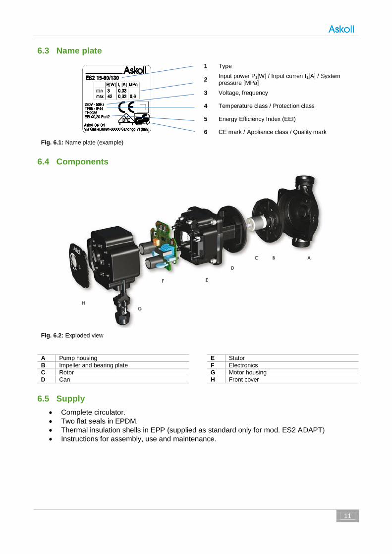
6.3 Name plate
1 Type
2 Input power P1[W] / Input curren I1[A] / System pressure [MPa]
3 Voltage, frequency
4 Temperature class / Protection class
5 Energy Efficiency Index (EEI)
6 CE mark / Appliance class / Quality mark
Fig. 6.1: Name plate (example)
6.4 Components
Fig. 6.2: Exploded view
A Pump housing E Stator
B Impeller and bearing plate F Electronics
C Rotor G Motor housing
D Can H Front cover
6.5 Supply
Complete circulator.
Two flat seals in EPDM.
Thermal insulation shells in EPP (supplied as standard only for mod. ES2 ADAPT)
Instructions for assembly, use and maintenance.
ENERGY SAVING
12 Product information
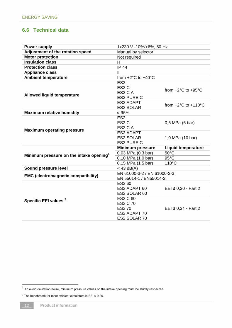
6.6 Technical data
Power supply 1x230 V -10%/+6%, 50 Hz
Adjustment of the rotation speed Manual by selector
Motor protection Not required Insulation class H
Protection class IP 44
Appliance class II
Ambient temperature from +2°C to +40°C
Allowed liquid temperature
ES2 ES2 C ES2 C A ES2 PURE C
from +2°C to +95°C
ES2 ADAPT ES2 SOLAR
from +2°C to +110°C
Maximum relative humidity ≤ 95%
Maximum operating pressure
ES2 ES2 C ES2 C A
0,6 MPa (6 bar)
ES2 ADAPT ES2 SOLAR ES2 PURE C
1,0 MPa (10 bar)
Minimum pressure on the intake opening1
Minimum pressure Liquid temperature
0.03 MPa (0.3 bar) 50°C
0.10 MPa (1.0 bar) 95°C
0.15 MPa (1.5 bar) 110°C
Sound pressure level < 43 dB(A)
EMC (electromagnetic compatibility) EN 61000-3-2 / EN 61000-3-3 EN 55014-1 / EN55014-2
Specific EEI values 2
ES2 60 ES2 ADAPT 60 ES2 SOLAR 60
EEI ≤ 0,20 - Part 2
ES2 C 60 ES2 C 70 ES2 70 ES2 ADAPT 70 ES2 SOLAR 70
EEI ≤ 0,21 - Part 2
1 To avoid cavitation noise, minimum pressure values on the intake opening must be strictly respected.
2 The benchmark for most efficient circulators is EEI ≤ 0,20.

13
To avoid condensation in the motor and the electronics the temperature of the pumped liquid must always be greater than the ambient temperature.
Ambient temperature
Liquid temperature
[°C] Min. [°C] Max. [°C]
ES2 ES2 C
0 2 95
10 10 95
20 20 95
30 30 95
35 35 90
40 40 70
ES2 ADAPT ES2 SOLAR
0 2 110
10 10 110
20 20 110
30 30 110
35 35 90
40 40 70

ENERGY SAVING
14 Installation at Site
7 Installation at Site
Installation and service by qualified personnel only!
7.1 Installation
The circulator must be mounted in a stable/fixed position in a dry, well ventilated, frost-free, waterproof and protected place, with sufficient ventilation around it. Assemble the circulator only after having ended all welding and brazing works on the hosing. Before installing the circulator, make sure that the internal part of the tubes is clean. Install the circulator in an accessible place for future checks and disassembly procedures. Foresee enough space for inspections and disassembling. Foresee isolating valves at intake and output (before and after the circulator) to allow the disassembly without emptying the plant. The assembly of the interception organs must be carried out in such a way as to prevent possible water leaks from involving the terminal board. Perform the assembly without mechanical stresses acting on the circulator.
Avoid the installation in misaligned pipe work.
Fig. 7.1: Mounting procedure.
The direction of the water flow is indicated by the arrow on the pump housing, as shown in Fig. 7.1. 1. Check that both isolating valves are closed 2. Install the circulator with the motor shaft in horizontal position. Connect the piping without
transmitting any stresses and strains. 3. Accurately insert the two gaskets supplied. 4. Establish a screwed connection between circulator and piping. 5. Tighten the screwed connection hand with an assembly tool (e.g. pipe wrench).

15
Thread Pump housing material
Tightening torque
G1 Composite PA 66 GF Max. 50 Nm
G1 Cast Iron EN-GJL-200 Max. 85 Nm
G1½ Cast Iron EN-GJL-200 Max. 125 Nm
G2 Cast Iron EN-GJL-200 Max. 165 Nm
7.2 Permissible installation positions
Install the circulator with horizontal motor shaft axis (Fig. 7.2).
Fig. 7.2: Permissible installation positions
7.3 Motor housing regulation
The motor body can be rotated in the positions shown in Fig. 7.3.
Pay utmost care to prevent people from getting in contact with the hot surfaces of the circulator. Drain the system or close the isolating valves on either side of the pump before the screws are removed. The pumped liquid may be scalding hot and under high pressure.
Pay attention not to damage the seal of the pump housing. CAUTION
Fig. 7.3: Motor housing positions

ENERGY SAVING
16 Installation at Site
Procedure (Fig. 7.4):
1. Slacken and remove the four screws M5 holding the motor. 2. Turn the motor to the desired position without extracting it from the pump housing. 3. Insert and tighten the pump housing screws (The tightening torque of the screws of the
pump housing must correspond to a value of 3.3 ± 0.5 Nm).
7.4 Insulation of pump housing
Fig. 7.5: Insulation of pump housing
The heat loss from the pump and pipework can be reduced by insulating the pump housing and the pipe with the thermal insulation shells supplied with the circulator (supplied as standard only with model ES2 ADAPT) → Fig. 7.5.
The thermal insulation shells can be ordered separately.
Do not insulate the control box or cover the control panel. CAUTION
Fig. 7.4: Changing the motor body position

17
8 Electric connection
The electric connection has to be performed by a qualified electrician in compliance with the national regulations. Follow the safety regulations and installation regulations of your country.
Connection to the power supply must be carried out in compliance with the standards via a fixed power cable which is fitted with a plug-type connection or an all-pole isolating switch with a minimum contact opening of 3 mm.
The circulator belongs to class II and therefore grounding is not necessary. The circulator does not require any external protection of the motor. Compare the frequency and the voltage of the mains with the rating data. All electric information concerning the circulator is on the signaling plate. The connection cord must be laid in such a way as it cannot come in contact with the hosing or the motor body. In case of use of the circulator with fluids at a temperature higher than 70 °C, use a connection cord resistant to high temperatures.
Fig. 8.1: Electric connection
1. Connect the power supply conductors to the terminals according to the diagram given in Fig. 8.1, from A to C.
2. Insert the terminal board in the proper seat, connecting the blue wire (neutral) with letter N and the black/brown wire (phase) with letter L. (Fig. 8.1.D).
3. Screw the two screws (Fig. 8.1.E - The tightening torque of the screws must correspond to a maximum value of 0,3 Nm).
4. Tighten the sealing nuts to the fairlead (Fig. 8.1.F - The tightening torque must correspond to a maximum value of 2 Nm).
5. The LED light, if lighted, indicates that the power supply is present. (Fig. 8.1.G).

ENERGY SAVING
18 Commissioning
9 Commissioning
9.1 Start-up of the circulator
Absolutely avoid dry operation. Start the circulator only after having completely filled the plant. CAUTION
Circulators with permanent magnets can not be driven in speed by means of phase control of the supply voltage. CAUTION
Circulators driven by an electronic frequency converter have a current peak at each activation (inrush current) greater than traditional circulators (asynchronous). The activation stage of the circulator has to be size taking into account this current peak. For further details contact the manufacturer.
CAUTION
Activation frequency: activations/deactivations through the mains voltage ≤ 20/24 h.
9.2 Operating elements
Selector
All settings are made using the selector on the housing front. The selector can be adjusted in a continuous way with a rotation angle of 270 °. The arrow on the selector indicates the operating mode chosen.
LED light
The LED light on the front advises the commissioning/fault of the circulator. Every operating mode is characterized by a fixed light of different colour. After a change of operating mode, the LED pulses 5 times. The pulse will be a change of brightness intensity of the LED light.
Fig. 9.1: Selector and LED light
19
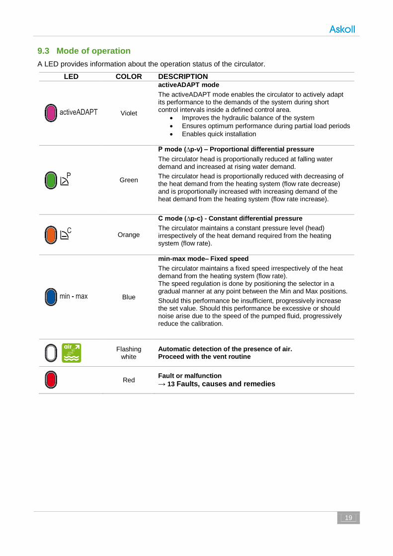
9.3 Mode of operation
A LED provides information about the operation status of the circulator.
LED COLOR DESCRIPTION
Violet
activeADAPT mode
The activeADAPT mode enables the circulator to actively adapt its performance to the demands of the system during short control intervals inside a defined control area.
Improves the hydraulic balance of the system
Ensures optimum performance during partial load periods
Enables quick installation
Green
P mode (∆p-v) – Proportional differential pressure
The circulator head is proportionally reduced at falling water demand and increased at rising water demand.
The circulator head is proportionally reduced with decreasing of the heat demand from the heating system (flow rate decrease) and is proportionally increased with increasing demand of the heat demand from the heating system (flow rate increase).
Orange
C mode (∆p-c) - Constant differential pressure
The circulator maintains a constant pressure level (head) irrespectively of the heat demand required from the heating system (flow rate).
Blue
min-max mode– Fixed speed
The circulator maintains a fixed speed irrespectively of the heat demand from the heating system (flow rate). The speed regulation is done by positioning the selector in a gradual manner at any point between the Min and Max positions.
Should this performance be insufficient, progressively increase the set value. Should this performance be excessive or should noise arise due to the speed of the pumped fluid, progressively reduce the calibration.
Flashing white
Automatic detection of the presence of air. Proceed with the vent routine
Red Fault or malfunction
→ 13 Faults, causes and remedies

ENERGY SAVING
20 Commissioning
9.4 Automatic detection of the presence of air - Vent system.
Fig. 9.2: Filling and venting of heating systems
Fill and bleed the system correctly.
The circulator can be noisy at start due to the presence of air. Such noise should stop after few minutes of operation. Usually the pump rotor chamber normally bleeds automatically after a short time in operation.
The circulator is equipped with a special software system that detects the presence of excess of air within the heating system. The LED shows the presence of air in the hydraulic circuit by flashing and performing a rapid succession of WHITE colour.
Following the light signal, it’s possible to easily vent the heating system as follows: 1. Open the air vent valve in the hydraulic circuit above the circulator or open the cap of the
air separator in the pump housing, partially unscrewing it; when unscrewing the cap of the air separator, beware of not losing the cap itself;
2. set the circulator to MAX position (maximum performance setting); 3. let the circulator run for a short period, according to the construction and the plant size; 4. once vented the system - the guide light (LED) stops blinking and the possible noise stops -
set the circulator as indicated in Par.10 Circulator setting
Repeat the procedure if necessary.
The plant cannot be drained by using the circulator. CAUTION
With solar thermal systems, fill the system with mixtures prepared for that application. The circulator cannot be used to mix the fluids in the system.
Do not touch the fluid or the circulator when the temperature is greater than 60 °C. Hazard of scalding by simple contact.
21
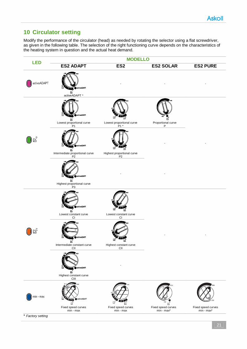
10 Circulator setting
Modify the performance of the circulator (head) as needed by rotating the selector using a flat screwdriver, as given in the following table. The selection of the right functioning curve depends on the characteristics of the heating system in question and the actual heat demand.
LED MODELLO
ES2 ADAPT ES2 ES2 SOLAR ES2 PURE
activeADAPT *
- - -
Lowest proportional curve
P1
Lowest proportional curve
P1 *
Proportional curve
P
-
Intermediate proportional curve
P2
Highest proportional curve
P2
-
Highest proportional curve
P3
- -
Lowest constant curve
CI
Lowest constant curve
CI
- -
Intermediate constant curve
CII
Highest constant curve
CII
Highest constant curve
CIII
-
Fixed speed curves
min - max
Fixed speed curves
min - max
Fixed speed curves
min - max*
Fixed speed curves
min - max*
* Factory setting

ENERGY SAVING
22 Performance curves
11 Performance curves
11.1 Performance curves - ES2 60
11.2 Performance curves - ES2 70

23
11.3 Performance curves - ES2 C 60
11.4 Performance curves - ES2 C 70

ENERGY SAVING
24 Performance curves
11.5 Performance curves - ES2 ADAPT 60
11.6 Performance curves - ES2 ADAPT 70

25
11.7 Performance curves - ES2 SOLAR 60
11.8 Performance curves - ES2 SOLAR 70

ENERGY SAVING
26 Performance curves
11.9 Performance curves - ES2 PURE C 40

27
12 Maintenance
The circulator does not require any special maintenance during operation. Motor bearings are lubricated by the pumped liquid.
Before each maintenance intervention, disconnect power supply and wait for the circulator to cool.
13 Faults, causes and remedies
13.1 Fault finding table
FAULTS CONTROL PANEL
CAUSES REMEDIES
The circulator is noisy
LED on Suction pressure is insufficient - cavitation
Increase the system suction pressure within the permissible range.
LED on Presence of foreign bodies in the impeller
Disassemble the motor and clean the impeller
Loud noises of water circulation
Flashing white LED
Air in the system Vent the system (→ 9.4 Automatic detection of the presence of air - Vent system.)
LED on The flow is too high Reduce the rotation speed (→ 10 Circulator setting)
Circulator is not running although the electrical power supply is switched on
LED off
Lack of power supply Verify voltage value of the electric plant Verify the connection of the motor
One fuse in the installation is blown
Verify the fuses of the plant
The circulator is defective Replace the pump.
Overheating
Let the pump cool down for some minutes. Then try to re-start it. Verify that the water and ambient temperature are within the indicated temperature ranges.
LED red
The rotor is blocked
Disassemble the motor and clean the impeller if the Should you fail to eliminate the cause of
the malfunction, refer to the Distributor or nearest Service Center.
doesn’t succeed (→ 13.2)
Insufficient supply voltage Verify that the power supply matches the data on the name plate.
Building does not get warm.
LED on The circulator performance is too low
Increase the suction head (→10 Circulator setting)

ENERGY SAVING
28 Spare parts
Should you fail to eliminate the cause of the malfunction, refer to the Distributor or nearest Service Center.
13.2 Unlocking procedure
A red light in the LED indicates a locking. Turn the selector to the position max, disconnect and connect power supply to start the automatic
release process. The circulator operates 100 attempts to restart (process lasts approximately 15 minutes). Every restart is signalled by a short flash of LED light. If the locking is not removed through the automatic release process after 100 attempts to restart the circulator, it goes into standby and the LED remains red. In this case follow the manual procedure described in the next steps: during any attempt, the red LED light keeps blinking; after that the circulator tries again to start. If the locking is not removed through the automatic release process (the warning light returns to be red), it is necessary to perform the manual proceeding described in the next steps: Disconnect power supply - the warning light switches off. Close the interception organs upstream and downstream of the circulator and let it cool. Disassemble the motor and clean the impeller.
1. Disconnect power supply - the warning light switches off. 2. Close both isolating valves and allow cooling. If there are no shut-off devices, drain the
system so that the fluid level is beneath that of the circulator. 3. Carefully pull the rotor/impeller 4. Remove impurities and deposits with appropriate agents. 5. Reinsert the rotor/impeller 6. Set the selector on the wished position. 7. Connect power supply.
If the circulator doesn’t run → 13 Faults, causes and remedies.
With high fluid temperatures and pressures there is the risk of burnings. Hazard of scalding by simple contact.
14 Spare parts
Spare parts are ordered via local specialist retailers. Should you need to order any spare parts, always provide all rating data of the circulator.
15 Disposal
The correct disposal and recycling of this product will prevent damage to the environment and risks to human health.
1. Use public or private disposal organisations when disposing of all or part of the product. 2. For information about proper disposal, it is necessary to ask to the city administration, the
authorized office or the retailers of the product.
Reserved right of modification

Askoll Sei S.r.l. - Via Galileo Galilei, 89/91 - 36066 Sandrigo (VI) - ITALY
Tel. +39 0444 666800 | Fax. +39 0444 666801
www.askoll.com
MK
TG
-HE
A-E
S2M
AN
-000-1
0/1
4-E
NG
-A6


![Z184 ES2 03+ZEN Support Software+OperManual[1]](https://static.fdocuments.in/doc/165x107/5571f7f549795991698c5a24/z184-es2-03zen-support-softwareopermanual1.jpg)