
Installation and Operation Guide - Cisco€¦ · indicates an infrared laser that transmits...
136
4014102 Rev C Dual SFP Gigabit QAM Modulator Installation and Operation Guide
Transcript of Installation and Operation Guide - Cisco€¦ · indicates an infrared laser that transmits...

4014102 Rev C
Dual SFP Gigabit QAM Modulator Installation and Operation Guide


Please Read
Important
Please read this entire guide. If this guide provides installation or operation instructions, give particular attention to all safety statements included in this guide.

Notices
Trademark acknowledgements
Cisco and the Cisco logo are trademarks or registered trademarks of Cisco and/or its affiliates in the U.S. and other countries. A listing of Cisco's trademarks can be found at www.cisco.com/go/trademarks.
Third party trademarks mentioned are the property of their respective owners.
The use of the word partner does not imply a partnership relationship between Cisco and any other company. (1009R)
Publication disclaimer
Cisco Systems, Inc. assumes no responsibility for errors or omissions that may appear in this publication. We reserve the right to change this publication at any time without notice. This document is not to be construed as conferring by implication, estoppel, or otherwise any license or right under any copyright or patent, whether or not the use of any information in this document employs an invention claimed in any existing or later issued patent.
Copyright
© 2007, 2012 Cisco and/or its affiliates. All rights reserved. Printed in the United States of America.
Information in this publication is subject to change without notice. No part of this publication may be reproduced or transmitted in any form, by photocopy, microfilm, xerography, or any other means, or incorporated into any information retrieval system, electronic or mechanical, for any purpose, without the express permission of Cisco Systems, Inc.

4014102 Rev C iii
Contents
Safety Precautions v
FCC Compliance ix
About This Guide xi
Introduction 1
System Overview ..................................................................................................................... 3 Input/Output Process ............................................................................................................. 6 Front Panel Overview ............................................................................................................. 7 Back Panel Overview ............................................................................................................... 9
Installing the Dual SFP GQAM 13
Installation Process Summary .............................................................................................. 14 Unpack and Inspect the GQAM .......................................................................................... 17 Record the MAC Address ..................................................................................................... 18 Stacking Guidelines ............................................................................................................... 19 Install the Modulator Into a Rack ........................................................................................ 23 Connect Power Sources ......................................................................................................... 26 Connect the DVB ASI Input Ports ....................................................................................... 28 Connect the 10/100BaseT Ethernet Port ............................................................................. 30 Connect the Gigabit Ethernet Ports ..................................................................................... 32 Connect the RF OUT Ports ................................................................................................... 34
Provisioning the Dual SFP GQAM 37
Understand the GUIs............................................................................................................. 38 Provision GQAMs on the DNCS ......................................................................................... 51 Add a Service Group ............................................................................................................. 56

Contents
iv 4014102 Rev C
Operating the Modulator 61
Understand the Boot Process ............................................................................................... 62 Change the Boot Mode .......................................................................................................... 65 Read the Default Status Screen ............................................................................................ 67 Use the Front Panel Keys to Change Configuration Settings .......................................... 68 Adjust the Frequencies of a Selected RF Channel or CH Carrier .................................... 71 Adjust the RF Output Level of a Selected Carrier ............................................................. 73 Mute the RF Output of a Selected CH Carrier ................................................................... 74 Change the Carrier Mode of a Selected CH Carrier .......................................................... 75 Monitor Setup Options .......................................................................................................... 76 Inspect the Modulator ........................................................................................................... 85 Replace the Fuse ..................................................................................................................... 86 Diagnose the Fan .................................................................................................................... 88 Replace the Fan ...................................................................................................................... 90
Troubleshooting the GQAM 93
Alarm Conditions .................................................................................................................. 94 Troubleshooting Alarm Messages ....................................................................................... 96 Troubleshooting Boot Screen Error Messages ................................................................. 104
Customer Information 109
Appendix A Technical Specifications 111
Installation and Operation Requirements ........................................................................ 112 RF Specifications .................................................................................................................. 114 ASI Input Specifications ...................................................................................................... 115 Modulation Specifications .................................................................................................. 116 Digital I/O Performance Specifications ............................................................................ 117 Connector Type .................................................................................................................... 118 Factory Default Settings ...................................................................................................... 119 Standard Output Frequencies ............................................................................................ 120
Index 121

Safety Precautions
4014102 Rev C v
Safety Precautions
Read, Retain, and Follow These Instructions Carefully read all safety and operating instructions before operating this product. Follow all operating instructions that accompany this product. Retain the instructions for future use. Give particular attention to all safety precautions.
Warning and Caution Icons
WARNING:
Avoid personal injury and product damage! Do not proceed beyond any icon until you fully understand the indicated conditions.
The following icons alert you to important information about the safe operation of this product:
You will find this icon in the literature that accompanies this product. This icon indicates important operating or maintenance instructions.
You may find this icon affixed to this product and in this document to alert you of electrical safety hazards. On this product, this icon indicates a live terminal; the arrowhead points to the terminal device.
You may find this icon affixed to this product. This icon indicates a protective earth terminal.
You may find this icon affixed to this product. This icon indicates excessive or dangerous heat.
You may find this symbol affixed to this product and in this document. This symbol indicates an infrared laser that transmits intensity-modulated light and emits invisible laser radiation and an LED that transmits intensity-modulated light.
Heed All Warnings Adhere to all warnings on the product and in the operating instructions.
Avoid Electric Shock Follow the instructions in this warning.
WARNING:
To reduce risk of electric shock, perform only the instructions that are included in the operating instructions. Refer all servicing to qualified service personnel.

Safety Precautions
vi 4014102 Rev C
Servicing
WARNING:
Avoid electric shock! Opening or removing the cover may expose you to dangerous voltages.
Do not open the cover of this product and attempt service unless instructed to do so in the operating instructions. Refer all servicing to qualified personnel only.
Cleaning, Water, Moisture, Open Flame To protect this product against damage from moisture and open flames, do the following:
Before cleaning, unplug this product from the AC outlet. Do not use liquid or aerosol cleaners. Use a dry cloth for cleaning.
Do not expose this product to moisture.
Do not place this product on a wet surface or spill liquids on or near this product.
Do not place or use candles or other open flames near or on this product.
Ventilation To protect this product against damage from overheating, do the following:
This product has openings for ventilation to protect it from overheating. To ensure product reliability, do not block or cover these openings.
Do not open this product unless otherwise instructed to do so.
Do not push objects through openings in the product or enclosure.
Placement To protect this product against damage from breakage, do the following:
Place this product close enough to a mains AC outlet to accommodate the length of the product power cord.
Route all power supply cords so that people cannot walk on, or place objects on, or lean objects against them. This can pinch or damage the cords. Pay particular attention to cords at plugs, outlets, and the points where the cords exit the product.
Make sure the mounting surface or rack is stable and can support the size and weight of this product.
WARNING:
Avoid personal injury and damage to this product! An unstable surface may cause this product to fall.

Safety Precautions
4014102 Rev C vii
When moving a cart that contains this product, check for any of the following possible hazards:
Move the cart slowly and carefully. If the cart does not move easily, this condition may indicate obstructions or cables that you may need to disconnect before moving this cart to another location.
Avoid quick stops and starts when moving the cart.
Check for uneven floor surfaces such as cracks or cables and cords.
WARNING:
Avoid personal injury and damage to this product! Move any appliance and cart combination with care. Quick stops, excessive force, and uneven surfaces may cause the appliance and cart to overturn.
Fuse When replacing a fuse, heed the following warnings.
WARNING:
Avoid electric shock! Always disconnect all power cables before you change a fuse.
WARNING:
Avoid product damage! Always use a fuse that has the correct type and rating. The correct type and rating are indicated on this product.
Grounding This Product (U.S.A. and Canada Only)
Safety Plugs
If this product is equipped with either a three-prong (grounding pin) safety plug or a two-prong (polarized) safety plug, do not defeat the safety purpose of the polarized or grounding-type plug. Follow these safety guidelines to properly ground this product:
For a 3-prong plug (consists of two blades and a third grounding prong), insert the plug into a grounded mains, 3-prong outlet.
Note: This plug fits only one way. The grounding prong is provided for your safety. If you are unable to insert this plug fully into the outlet, contact your electrician to replace your obsolete outlet.
For a 2-prong plug (consists of one wide blade and one narrow blade), insert the plug into a polarized mains, 2-prong outlet in which one socket is wider than the other.
Note: If you are unable to insert this plug fully into the outlet, try reversing the plug. The wide blade is provided for your safety. If the plug still fails to fit, contact an electrician to replace your obsolete outlet.

Safety Precautions
viii 4014102 Rev C
Grounding Terminal
If this product is equipped with an external grounding terminal, attach one end of an 18-gauge wire (or larger) to the grounding terminal; then, attach the other end of the wire to an earth ground, such as an equipment rack that is grounded.
20050727 Headend/Rack

FCC Compliance
4014102 Rev C ix
FCC Compliance Where this equipment is subject to U.S.A. FCC and/or Industry Canada rules, the following statements apply.
United States FCC Compliance This device has been tested and found to comply with the limits for a Class A digital device, pursuant to part 15 of the FCC Rules. These limits are designed to provide reasonable protection against such interference when this equipment is operated in a commercial environment.
This equipment generates, uses, and can radiate radio frequency energy, and if not installed and used in accordance with the instruction manual may cause harmful interference to radio communications. Operation of this equipment in a residential area is likely to cause harmful interference, in which case users will be required to correct the interference at their own expense.
Canada EMI Regulation This Class A digital apparatus complies with Canadian ICES-003.
Cet appareil numérique de la class A est conforme à la norme NMB-003 du Canada. 20061110 FCC HE


About This Guide
4014102 Rev C xi
About This Guide
Introduction
This guide describes the Model D9479-12 120/230 V AC Dual Small Form-Factor Pluggable (SFP) Gigabit QAM Modulator (GQAM) and the Model D9479-22 48 V DC Dual SFP GQAM. This guide provides installation, provisioning, operating, and troubleshooting procedures, as well as technical specifications.
Note: The Dual SFP GQAM is synonymous for GQAM throughout this document.
The Dual SFP GQAM features two gigabit Ethernet (GbE) ports, providing automatic or manual redundancy in the event of a signal or data loss. The second GbE port can also be used as an additional active program source.
Important: To utilize the Dual GbE ports requires System Releases (SR) 2.7/3.7 or SR 4.2. Although you can physically attach this modulator to systems running SR 4.0 Service Pack 2, you cannot provision or use the backup GbE port.
Purpose
This guide provides detailed specifications and component descriptions for the Dual SFP GQAM and it functions. This guide also includes installation, provisioning, and operational procedures needed for your cable network. Call center personnel can use this guide to assist them with common troubleshooting procedures.
Scope
This guide includes the following topics:
Descriptions of GQAM functions
Descriptions of GQAM components
Installation procedures
Operation procedures
Troubleshooting guidelines
Customer support information
GQAM technical specifications

About This Guide
xii 4014102 Rev C
Audience
This guide is written for cable network system administrators and engineers, DNCS operators, call center personnel, and system operators who are responsible for installing, operating, maintaining, and troubleshooting the GQAM.
Document Version
This is the first release of this document.

4014102 Rev C 1
The Dual SFP GQAM represents one of the most up-to-date innovations in video transmission technology. The GQAM contains six input ports and can provide up to sixteen QAM outputs for video data. The input ports include four Digital Video Broadcasting standard asynchronous serial interface inputs and dual Gigabit Ethernet (GbE) ports.
The GQAM provides automatic redundant switching between the main and backup GbE ports in response to a loss of signal or data. The data can be sent simultaneously on all four ASI inputs and one GbE port, and programs can be multiplexed to any of the sixteen outputs.
This device provides up to sixteen 6 MHz outputs while only occupying one rack unit (RU) in the equipment rack replacing the core functionality and the RF output capabilities of four Model D9477 Multi Quadrature Amplitude Modulation (MQAM) Modulators. For example, compared with the MQAM modulator, the GQAM frees up a total of seven additional RU openings, thereby making it the ideal product for mass deployment of video-on-demand, anything-On-Demand, and other interactive broadcast services. This modulator also provides four DVB ASI inputs (216 Mbps each) and a dual Small Form-Factor Pluggable (SFP) port to multiplex content from any input to any of the sixteen outputs (channels).
The Dual SFP GQAM enables a smooth transition to headend/hub architectures that can utilize the benefits of video networking using standard data network switches or routers. This is especially beneficial for on-demand applications, whether from storage or from broadcast sources. Switching (or routing) frees the architecture from the constraints of dedicated point-to-point source to edge asynchronous serial interface (ASI) interconnections, and switching permits independent optimization of source bandwidth, transport bandwidth, and edge or distribution bandwidth.
1 Chapter 1 Introduction
2 4014102 Rev C
This chapter describes how the Dual SFP GQAM functions within the Digital Broadband Delivery System (DBDS), explains how it processes and outputs data, and provides illustrations and descriptions of front and back panel components for the 120/230V AC and the 48V DC models.
In This Chapter
System Overview .................................................................................... 3
Input/Output Process ............................................................................ 6
Front Panel Overview ............................................................................ 7
Back Panel Overview.............................................................................. 9

System Overview
4014102 Rev C 3
System Overview
Diagram of Major DBDS Components
Depending on the system architecture, the GQAM can be used in either headends or hubs. The following illustration provides an example of where the GQAM can be used with the major components of the DBDS.
Features
The GQAM provides many new digital broadcast features and innovations for your system which are described in the following table.
Chapter 1 Introduction
4 4014102 Rev C
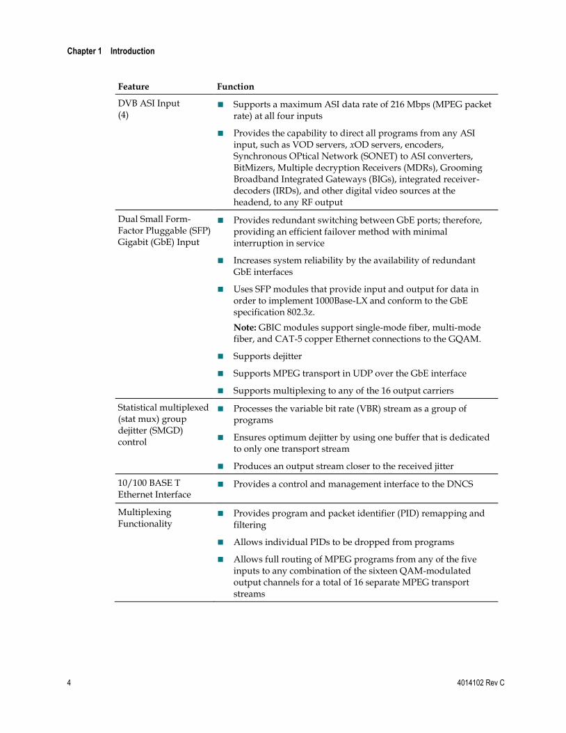
Feature Function
DVB ASI Input (4)
Supports a maximum ASI data rate of 216 Mbps (MPEG packet rate) at all four inputs
Provides the capability to direct all programs from any ASI input, such as VOD servers, xOD servers, encoders, Synchronous OPtical Network (SONET) to ASI converters, BitMizers, Multiple decryption Receivers (MDRs), Grooming Broadband Integrated Gateways (BIGs), integrated receiver-decoders (IRDs), and other digital video sources at the headend, to any RF output
Dual Small Form-Factor Pluggable (SFP) Gigabit (GbE) Input
Provides redundant switching between GbE ports; therefore, providing an efficient failover method with minimal interruption in service
Increases system reliability by the availability of redundant GbE interfaces
Uses SFP modules that provide input and output for data in order to implement 1000Base-LX and conform to the GbE specification 802.3z.
Note: GBIC modules support single-mode fiber, multi-mode fiber, and CAT-5 copper Ethernet connections to the GQAM.
Supports dejitter
Supports MPEG transport in UDP over the GbE interface
Supports multiplexing to any of the 16 output carriers
Statistical multiplexed (stat mux) group dejitter (SMGD) control
Processes the variable bit rate (VBR) stream as a group of programs
Ensures optimum dejitter by using one buffer that is dedicated to only one transport stream
Produces an output stream closer to the received jitter
10/100 BASE T Ethernet Interface
Provides a control and management interface to the DNCS
Multiplexing Functionality
Provides program and packet identifier (PID) remapping and filtering
Allows individual PIDs to be dropped from programs
Allows full routing of MPEG programs from any of the five inputs to any combination of the sixteen QAM-modulated output channels for a total of 16 separate MPEG transport streams

System Overview
4014102 Rev C 5
Feature Function
MPEG Stream Management
Provides program clock reference (PCR) timestamp correction
Provides program specific information (PSI) reconstruction
Provides transport stream monitoring
Allows adaptive insertion rate control
Stream Encryption, Conditional Access, and Management
Stream encryption modes: PowerKEY Native and the DVB Common Scrambling algorithm
Allows PowerKEY Book One ECM Handling
Provides MPEG packet insertion and entitlement control messages (ECMs)
Supports broadcast clear-to-air and interactive encrypted PowerKEY modes
64/256 QAM RF Output (4)
Provides four independently agile blocks of 6 MHz carriers for a total usable RF bandwidth of 24 MHz per output channel
Provides a separate physical connector for each block upconverter output
Allows independent level control for each QAM signal
Allows an adjustable output center frequency range of 91 MHz to 869 MHz
Allows an adjustable RF output signal level of 54 dBmV max per carrier, measured at the output F connector (+60 dBmV "equivalent" for 4 carriers)
Provides +/- 3 dB power adjustment between adjacent carriers, and 10 dB level range adjustment at each output
Provides a switched filter bank for superior broadband combined noise performance
Supports International Telecommunications Union (ITU) J.83 Annex-A, and Annex-B, and Annex-C standards
User Interface Features
Allows local setting of RF power levels and display of diagnostic and debug information through the front panel and user interface
Chapter 1 Introduction
6 4014102 Rev C
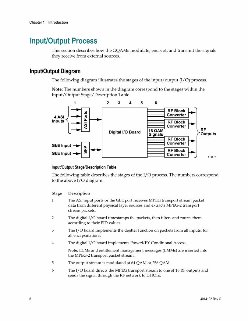
Input/Output Process This section describes how the GQAMs modulate, encrypt, and transmit the signals they receive from external sources.
Input/Output Diagram
The following diagram illustrates the stages of the input/output (I/O) process.
Note: The numbers shown in the diagram correspond to the stages within the Input/Output Stage/Description Table.
Input/Output Stage/Description Table
The following table describes the stages of the I/O process. The numbers correspond to the above I/O diagram.
Stage Description
1 The ASI input ports or the GbE port receives MPEG transport stream packet data from different physical layer sources and extracts MPEG-2 transport stream packets.
2 The digital I/O board timestamps the packets, then filters and routes them according to their PID values.
3 The I/O board implements the dejitter function on packets from all inputs, for all encapsulations.
4 The digital I/O board implements PowerKEY Conditional Access.
Note: ECMs and entitlement management messages (EMMs) are inserted into the MPEG-2 transport packet stream.
5 The output stream is modulated at 64 QAM or 256 QAM.
6 The I/O board directs the MPEG transport stream to one of 16 RF outputs and sends the signal through the RF network to DHCTs.
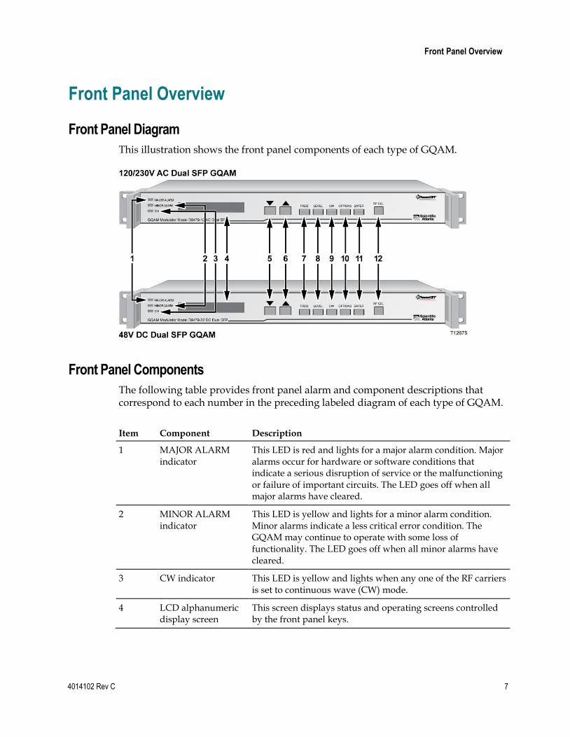
Front Panel Overview
4014102 Rev C 7
Front Panel Overview
Front Panel Diagram
This illustration shows the front panel components of each type of GQAM.
Front Panel Components
The following table provides front panel alarm and component descriptions that correspond to each number in the preceding labeled diagram of each type of GQAM.
Item Component Description
1 MAJOR ALARM indicator
This LED is red and lights for a major alarm condition. Major alarms occur for hardware or software conditions that indicate a serious disruption of service or the malfunctioning or failure of important circuits. The LED goes off when all major alarms have cleared.
2 MINOR ALARM indicator
This LED is yellow and lights for a minor alarm condition. Minor alarms indicate a less critical error condition. The GQAM may continue to operate with some loss of functionality. The LED goes off when all minor alarms have cleared.
3 CW indicator This LED is yellow and lights when any one of the RF carriers is set to continuous wave (CW) mode.
4 LCD alphanumeric display screen
This screen displays status and operating screens controlled by the front panel keys.

Chapter 1 Introduction
8 4014102 Rev C
Item Component Description
5
The Down Arrow key decrements a displayed value or navigates through a set of displayed values. This key is only active when the display has a flashing value, which indicates that the value can be changed. This key is primarily used for decreasing a displayed value such as frequency or level.
6
The Up Arrow key increments a displayed value or navigates through a set of values. This key is only active when the display has a flashing value, which indicates that the value can be changed. This key is primarily used for incrementing a displayed value such as frequency or level.
7 FREQ
The Frequency key selects the frequency display screen on which you can adjust the RF output frequency for each of the RF carriers.
8 LEVEL
The Level key selects the RF Output Level screen on which you can adjust the RF output power level and mute the RF output (42 dBmV to 56 dBmV).
9 CW
The Continuous Wave (CW) key selects the Continuous Wave Screen on which you can set the GQAM modulator to output either a modulated carrier or a continuous carrier for each of the RF carriers.
Note: CW mode is used for testing and not for normal operation.
10 OPTIONS
The Options key scrolls through status information and setup options.
11 ENTER
The Enter key saves configuration changes to nonvolatile memory.
12 RF SEL
The RF Port Selection (RF SEL) key selects one of the 16 RF outputs.
Back Panel Overview
4014102 Rev C 9
Back Panel Overview
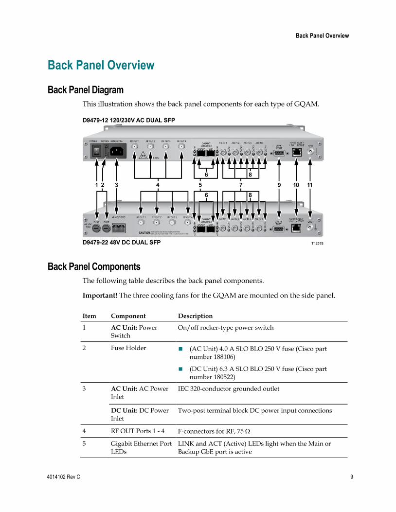
Back Panel Diagram
This illustration shows the back panel components for each type of GQAM.
Back Panel Components
The following table describes the back panel components.
Important! The three cooling fans for the GQAM are mounted on the side panel.
Item Component Description
1 AC Unit: Power Switch
On/off rocker-type power switch
2 Fuse Holder (AC Unit) 4.0 A SLO BLO 250 V fuse (Cisco part number 188106)
(DC Unit) 6.3 A SLO BLO 250 V fuse (Cisco part number 180522)
3
AC Unit: AC Power Inlet
IEC 320-conductor grounded outlet
DC Unit: DC Power Inlet
Two-post terminal block DC power input connections
4 RF OUT Ports 1 - 4 F-connectors for RF, 75
5 Gigabit Ethernet Port LEDs
LINK and ACT (Active) LEDs light when the Main or Backup GbE port is active

Chapter 1 Introduction
10 4014102 Rev C
6 Gigabit Ethernet ports
MAIN and BACKUP SFP GbE ports allow for the receipt of MPEG transport stream data in UDP over the GbE interface
7 DVB ASI INPUTS 1-4 Female BNC, 75 connector. Allows for the input of MPEG-2 transport stream data at a maximum rate of 216 Mbps
8 DVB ASI LEDs Data LEDs 1 through 4 light when the DVB ASI Input ports are receiving valid MPEG-2 transport stream packets
9 CRAFT PORT For Cisco diagnostic use only
10 10/100BASE T port Ethernet port shares data with DNCS Ethernet hub
11 GND Ground screw for grounding the modulator
Back Panel Indicator Lights
The following illustration and table show the back panel indicator lights.
Item Indicator Light Description
1
ACT/LINK (green) (BACKUP)
ACT: Lights when data traffic is on the 10/1000BaseT GbE link for the backup device
LINK: Lights when a valid GbE 10/1000BaseT link connection exists for the backup device
2
ACT/LINK (green) (MAIN)
ACT: Lights when data traffic is on the 10/1000BaseT GbE link for the primary (main) device
LINK: Lights when a valid GbE 10/1000BaseT link connection exists for the primary (main) device
3 DATA 1 (green) Lights when the DVB ASI Input 1 port is receiving valid MPEG-2 transport stream (TS) packets
4 DATA 2 (green) Lights when the DVB ASI Input 2 port is receiving valid MPEG-2 TS packets
5 DATA 3 (green) Lights when the DVB ASI Input 3 port is receiving valid MPEG-2 TS packets

Back Panel Overview
4014102 Rev C 11
6 DATA 4 (green) Lights when the DVB ASI Input 4 port is receiving valid MPEG-2 TS packets
7 LINK (yellow) Lights when a valid 10/100BaseT Ethernet link connection exists
8 ACTIVE (green) Lights when data traffic is on the 10/100BaseT Ethernet link

4014102 Rev C 13
Introduction
This chapter describes how to install the GQAM into a rack and where to connect it to the other components within the DBDS. The connections shown in this chapter may vary according to its use in your system.
Note: Refer to Technical Specifications (on page 111) for additional data and requirements to help you install and configure the GQAM in your system.
2 Chapter 2 Installing the Dual SFP GQAM
In This Chapter
Installation Process Summary ............................................................. 14
Unpack and Inspect the GQAM ......................................................... 17
Record the MAC Address .................................................................... 18
Stacking Guidelines .............................................................................. 19
Install the Modulator Into a Rack ....................................................... 23
Connect Power Sources ........................................................................ 26
Connect the DVB ASI Input Ports ...................................................... 28
Connect the 10/100BaseT Ethernet Port ............................................ 30
Connect the Gigabit Ethernet Ports .................................................... 32
Connect the RF OUT Ports .................................................................. 34
Chapter 2 Installing the Dual SFP GQAM
14 4014102 Rev C
Installation Process Summary
Introduction
This section provides the installation process and lists the detailed procedures in this guide that correspond with each process step.
Important! To ensure proper installation, read this entire guide before starting installation and then follow these processes in the order shown.
Before You Begin
This process assumes that you have already installed the GQAM software on the DNCS. Refer to the GQAM Software Version 4.0.6 Release Notes and Installation Instructions, for detailed instructions. Also be sure that you have access to the Digital Network Control System Online Help before starting installation.
Installation Processes
The following process summary provides the recommendations for installation.
Stage Process See Procedure
1 Review system requirements and technical specifications.
Installation Requirements (on page 23)
Installation and Operation Requirements (on page 112)
2 Consult your Bandwidth Management Plan and the input/output specifications to allocate your bandwidth resources properly.
Installation Requirements (on page 23)
Installation and Operation Requirements (on page 112)
3 Unpack and inspect the Dual SFP GQAM
Unpack and Inspect the GQAM (on page 17)
4 Record the MAC address from the label located on the underside of the modulator.
Record the MAC Address (on page 18)
5 Install the Dual SFP GQAM into a rack. Stacking Guidelines (on page 19)
Install the Modulator Into a Rack (on page 23)

Installation Process Summary
4014102 Rev C 15
Stage Process See Procedure
6 Connect the Dual SFP GQAM to an earth ground and then a power source.
From the 120/230 V AC port, connect the power cord.
From the 48V DC port, connect the power wires to the DC power inlet.
Connect Power Sources (on page 26)
7 Connect other network devices to the Dual SFP GQAM, except the RF out ports.
Connect the DVB ASI Input Ports (on page 28)
Connect the 10/100BaseT Ethernet Port (on page 30)
Insert the SFP modules into the GbE ports on the back panel and then connect the GbE ports
– Connecting the Gigabit Ethernet Port Using Fiber Optic Cables (on page 32)
– Connecting the Gigabit Ethernet Port Using CAT-5 Ethernet Cable (see "Connecting the Gigabit Ethernet Ports Using CAT-5 Ethernet Cables" on page 33)
8 Define the MPEG sources, add service groups (if using VOD or xOD), and provision the modulator using DNCS Element Provisioning according to your network wiring diagram.
Provision GQAMs on the DNCS (on page 51)
DNCS Online Help (PC) 4.2.0.3
9 Power on the modulator N/A
10 Ensure that the modulator boots correctly and check for alarms from the front panel.
Understand the Boot Process (on page 62)
Troubleshooting Alarm Messages (on page 96)
Troubleshooting Boot Screen Error Messages (on page 104)
11 Connect the RF output ports. Connecting the RF OUT Ports (on page 35)
12 Set the power output level in accordance with your network wiring diagram and spectrum analyzer measurements.
Adjust the RF Output Level of a Selected CH Carrier (see "Adjust the RF Output Level of a Selected Carrier" on page 73)

Chapter 2 Installing the Dual SFP GQAM
16 4014102 Rev C
Stage Process See Procedure
13 If sessions have been defined, verify the correct session count by pressing the OPTIONS button.
Viewing the Session Count (on page 77)
14 If encrypted, check the program count. Viewing the Program Count (on page 78)
15 Verify video and audio from a local DHCT.
See the post-upgrade procedures for your current System Release contained in the upgrade installation instructions.

Unpack and Inspect the GQAM
4014102 Rev C 17
Unpack and Inspect the GQAM
Carrier’s Responsibility
Cisco thoroughly inspects and carefully packs all products before shipment. The carrier is responsible for safe shipping and delivery.
If there are any missing parts or if there is damage to the product, contact Cisco Services.
Retain all boxes for future equipment shipping needs. The boxes are specifically designed for shipping the GQAM.
Unpacking and Inspecting Procedure
Complete the following steps to unpack and inspect the modulator.
1 Review the Safety Precautions.
2 Inspect the shipping carton for visible damage.
3 Open the shipping carton.
4 Remove all packing material.
5 Inspect the product for visible damage.
6 Inspect for loose items that may indicate concealed damage.
7 Inspect for missing parts using the packing slip as a guide.
8 Go to Record the MAC Address (on page 18).

Chapter 2 Installing the Dual SFP GQAM
18 4014102 Rev C
Record the MAC Address
Introduction
This section contains instructions for recording the MAC address as part of the installation process.
Recording the MAC Address 1 Unpack and inspect the modulator.
Note: Refer to Unpack and Inspect the GQAM (on page 17).
2 Locate the label containing the MAC addresses on the underside of the chassis.
Important! The GbE MAC addresses are typically the MAC address of the modulator plus 1 (one).
Examples:
GQAM MAC Address: 00:02:de:41:51:03
GbE MAC Address (Main): 00:02:de:41:51:04
GbE MAC Address (Backup): 00:02:de:41:51:05
3 Record the MAC addresses here:
- GQAM MAC Address: ______________________________________
- GbE MAC Address (Main): _______________________________________
- GbE MAC Address (Backup): _____________________________________
Important! You will need these MAC addresses for provisioning (configuring) the DNCS.
4 Go to Stacking Guidelines (on page 19).

Stacking Guidelines
4014102 Rev C 19
Stacking Guidelines
Introduction
The GQAM is a high-density, high performance device for digital broadband data delivery. One GQAM performs the services of two QAM modulators. This space-saving feature makes the GQAM the device of choice for contemporary digital broadband delivery systems.
Providing proper ventilation and cooling for the modulator is mandatory. You can stack up to 32 GQAM devices in a standard 40-rack unit (RU) equipment rack if you read and carefully follow the guidelines provided in this section and later in this chapter.
Each GQAM contains three dual fan packs that provide forced air cooling. These fan packs, located on the side of the unit, pull air across the internal circuitry to remove heat.
Important! In order for the fans to operate correctly, you must install each GQAM using the rack mount brackets included with the unit. These brackets contain notched cutout sections to allow for clearance so that air can enter and leave the unit without restriction.
When you install the GQAM in the rack using the rack mounts provided, you can install them directly above and below each other with no requirements for vented spacers. Using these rack mounts also provides support for the modulator. The GQAM is not intended to be suspended or “hung” in the rack by only mounting the front bezel support.
Controlling Operating Temperature
CAUTION:
Cisco headend equipment is designed to operate in a maximum 122°F (50°C) environment. Specifically, this means that the air temperature at the air inlet of any GQAM must never exceed 122°F (50°C).
Each GQAM draws up to 151 W of input power and a total of 515 BTU/hr. For a full rack with 32 units, the sum total is 4832 W per rack, or 16,480 BTU/hr. You should make your HVAC considerations based on these calculations.

Chapter 2 Installing the Dual SFP GQAM
20 4014102 Rev C
Controlling Exhaust Air
Exhaust air management is the key to cooling multiple modulators in a custom rack configuration. Inlet air temperature should be as cool as possible and should never exceed 122°F (50°C). Exhaust air should have little or no restrictions. Obstructions such as cabling or other devices that block airflow to the side or top of the rack should be avoided.
Considerations When Using Side by Side Equipment Racks
Often, side-by-side equipment racks will not include an internal wall between them. You should take extreme care when installing modulators in these types of systems. There is approximately an 18°F (10°C) rise from inlet air temperature to exhaust air temperature on a GQAM. This rise in temperature could have a cumulative effect on temperature from one rack to the adjacent one. You must take extreme care not to exceed the 122°F (50°C) maximum inlet air temperature requirement in these situations.
Considerations When Using Racks with a Wall on One Side
Rack installations that have the outer wall or side of the rack in place on the exhaust side of the GQAM should note that without sufficient airflow through the rack, the heated exhaust air may re-circulate back to the input side of the GQAM. Depending on the situation, this re-circulation air could eventually exceed the specified 122°F (50°C) maximum.
Measuring the Inlet Air Temperature
If you are concerned about inlet air temperature, you should measure the temperature of the inlet air in the actual rack as you plan to use it. You should have all cabling in place and all adjacent units installed and running.
Important! Opening the door on the back panel of the rack can have an adverse effect on the managed airflow. If access to the door on the back panel is not controlled, you should take the inlet air temperature with the back panel door open since, in most instances, opening the door will re-direct the airflow in an adverse manner.
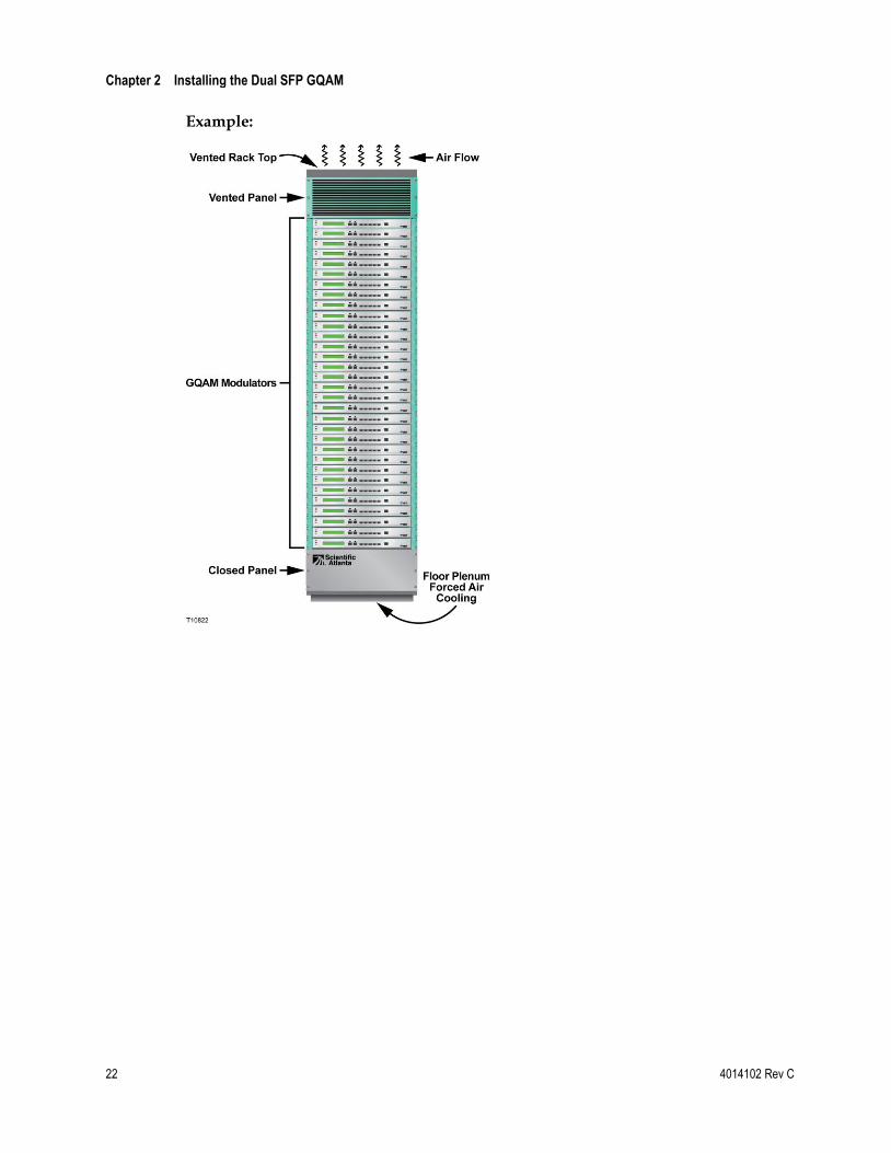
Stacking Considerations
You have two main options for stacking GQAMs in a rack. The option you choose depends on your system requirements. One option is to stack the GQAMs in a rack containing a top-mounted exhaust fan with vented panels on the front and back. The second option is to place a top-vented rack over a floor plenum forced air vent. The requirements for these two stacking options are described next in this section.
Option 1 – Using a Rack With a Top-Mounted Exhaust Fan
This stacking option uses a 40 RU configuration containing up to 32 GQAMs. The remaining 8 RUs are configured with 4 RUs at the bottom and 4 RUs at the top.

Stacking Guidelines
4014102 Rev C 21
The 4 RU space at the bottom is covered with a vented panel on both the front and the back. This panel allows air to freely enter the rack to cool the modulators.
The 4 RU space at the top is covered with a closed panel. This option uses an exhaust fan located on top of the rack to draw the heated air upward and out of the rack. The 4 RU space at the top allows the ventilation space needed for the exhaust fan to operate efficiently. The exhaust fan should be chosen so that a minimum of 600 cubic feet per minute (cfm) flows through the rack with 2000 cfm being the ideal amount.
Example:
Option 2 – Using a Rack With Floor Plenum Forced Air Cooling
This stacking option also uses a 40 RU configuration containing up to 32 GQAMs. In Option 2, however, the lower 4 RU space is covered with a solid panel instead of a vented one. The upper 4 RU space is vented along with the entire top of the rack. The floor plenum forced airflow must also be a minimum of 600 cfm with 2000 cfm being the ideal amount.
Chapter 2 Installing the Dual SFP GQAM
22 4014102 Rev C
Example:

Install the Modulator Into a Rack
4014102 Rev C 23
Install the Modulator Into a Rack
Introduction
The front bezel of the GQAM mounts to the front of the equipment rack. The GQAM fits into an EIA RS-310 rack mount.
Important! You must read the preceding section, Stacking Guidelines (on page 19), before installing the modulators into the rack.
Installation Requirements
This section lists the power, rack, and environmental conditions necessary for installation.
Power Requirements Table
Item Specification
Supply Voltage 90 V AC to 130 V AC @ 47 Hz to 63 Hz (AC unit)
180 V AC to 264 V AC @ 47 Hz to 63 Hz (AC unit)
-42 V to -57 V DC (DC unit)
Fuses 4.0 A SLO BLO 250 V (AC unit)
6.3 A SLO BLO 250 V (DC unit)
Line Frequency 47 Hz to 63 Hz (AC unit only)
Power Required 155 VA (typical)
Power Dissipated 151 Watts (typical)
In Rush Current 35 amps maximum, Vin = 130 VAC (AC unit)
75 amps maximum, Vin = 264 VAC (AC unit)
15 amps maximum, Vin = -57 VDC (DC unit)
Rack Requirements Table
Item Specification
Rack Mount Type EIA RS-310
Height 1.75 in./44.45 mm
Width 19 in./482.6 mm

Chapter 2 Installing the Dual SFP GQAM
24 4014102 Rev C
Depth 22.5 in./571.5 mm
Weight 13.5 lb./5.4 kg
Environmental Requirements Table
Item Specification
Operating Temperature 0°C (32°F) to 50°C (122°F)
CAUTION:
Avoid damage to this product! Your warranty is void if you operate this product above the maximum specified operating temperature.
Use caution when installing wiring and racks to avoid obstruction of air flow. The obstruction can occur at the side air vents of the GQAM or the vent fans at the GQAM side panel.
Important! You must use the supplied notched rack mounts (Cisco part numbers 734845 and 734846) to mount this modulator into the rack. These rack mounts allow correct air circulation through the unit.
Storage Temperature Range -10°C (14°F) to 70°C (158°F)
Operating Humidity 5% to 95%, non-condensing
Vibration Susceptibility No data errors with a chassis vibration of 0.5 Gs. No data errors with a vibration frequency of 10 Hz to 400 Hz
Electrostatic Shock Susceptibility No damage sustained from five discharges of 15 KV IEC electrostatic discharge model (150pF + 150 Ω) to all exposed connections
Installing the Modulator into a Rack
CAUTION:
Do not tangle or strain interconnecting cables.
Use caution when installing wiring and racks to avoid obstruction of airflow into the side air vents of the GQAM or out of the vent fans on the side of the GQAM.
IMPORTANT: You must use the supplied notched rack mounts to provide additional support and to allow correct air circulation through the unit.
1 Install the rack mounts.
Install the Modulator Into a Rack
4014102 Rev C 25
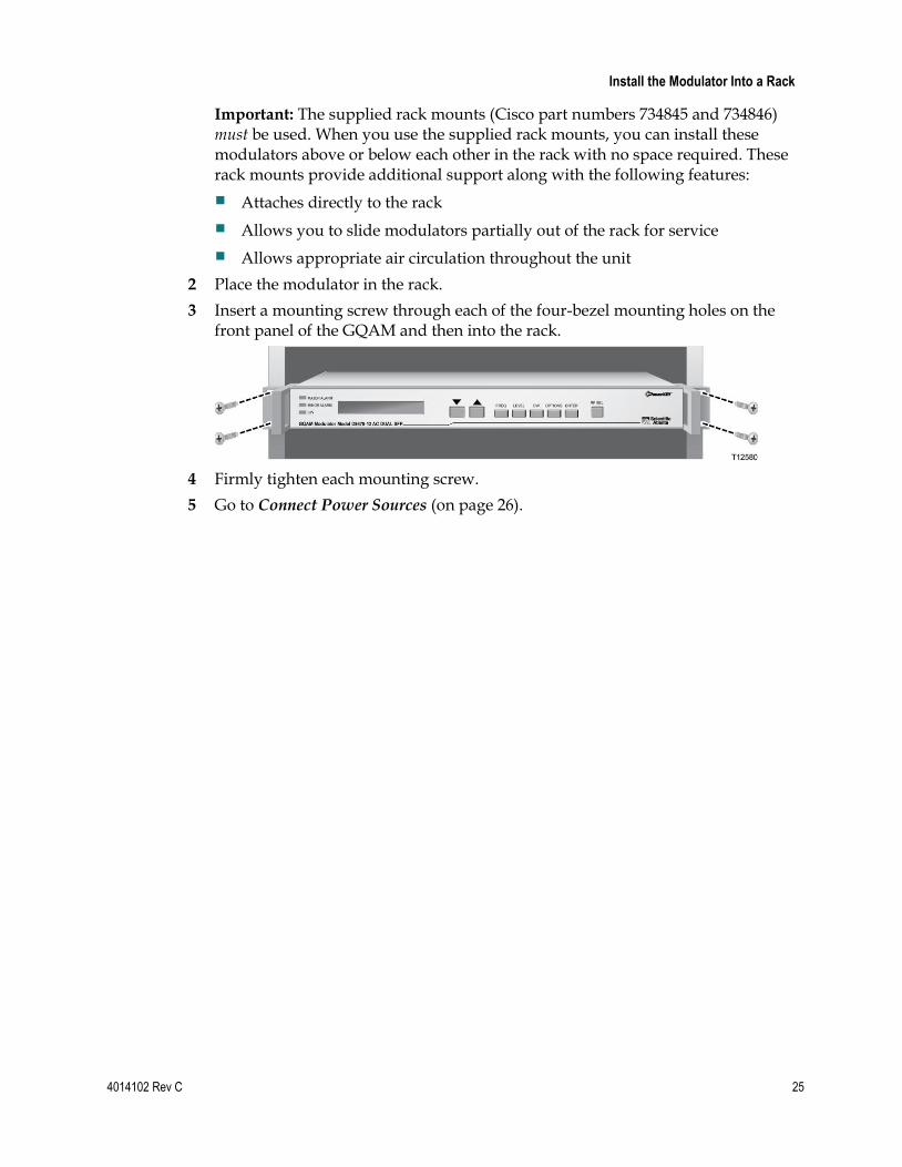
Important: The supplied rack mounts (Cisco part numbers 734845 and 734846) must be used. When you use the supplied rack mounts, you can install these modulators above or below each other in the rack with no space required. These rack mounts provide additional support along with the following features:
Attaches directly to the rack
Allows you to slide modulators partially out of the rack for service
Allows appropriate air circulation throughout the unit
2 Place the modulator in the rack.
3 Insert a mounting screw through each of the four-bezel mounting holes on the front panel of the GQAM and then into the rack.
4 Firmly tighten each mounting screw.
5 Go to Connect Power Sources (on page 26).
Chapter 2 Installing the Dual SFP GQAM
26 4014102 Rev C
Connect Power Sources
Introduction
This section contains instructions for connecting the DC and AC power sources to the modulator.
Connecting an Earth Ground
Complete the following steps to connect an earth ground to either the DC or AC versions of the GQAM.
CAUTION:
The 48 V DC GQAM must be connected to an earth ground.
1 Place a ground wire onto the ground lug (marked GND) on back of the GQAM; then, use your fingers to tighten the ground lug to secure the ground wire.
2 Connect the other end of the ground wire to the rack or earth ground.
Connecting a DC Power Source
Complete the following steps to connect a DC power source to the 48 V DC Dual SFP GQAM.
1 Verify that the DC power source is set to the Off position.
2 Insert the wires from the DC power source into the terminal block connector. Use a small flat-blade screwdriver to tighten the screws at the top of the terminal block connector to secure the wires.

Connect Power Sources
4014102 Rev C 27
3 Insert the terminal block connector into the terminal block on the back panel of the 48 V DC GQAM.
4 Keep the DC power source set to the Off position until you are ready to power on the modulator.
5 Go to Connect the DVB ASI Input Ports (on page 28).
Connecting an AC Power Source
Complete the following steps to connect an AC power source to the 120/230 V AC GQAM.
1 Verify that the power switch on the back panel is placed in the Off position.
2 Connect the power cord to the AC power inlet on the back panel of the 120/230 V AC GQAM.
3 Connect the other end of the power cord to an AC electrical outlet.
4 Keep the power switch in the Off position until you are ready to power on the device.
5 Go to Connect the DVB ASI Input Ports (on page 28).

Chapter 2 Installing the Dual SFP GQAM
28 4014102 Rev C
Connect the DVB ASI Input Ports
Description
Using ASI input pairs allows the device to receive data from ASI-compliant transmitting devices such as VOD servers, grooming BIGs, and MPEG multiplexers. These ASI inputs conform to the DVB document A010.
The DVB ASI input ports are BNC-type connectors and connect to 75 coaxial cables. Each DVB ASI Input port allows for the input of MPEG-2 transport stream (TS) data at a maximum rate of 216 Mbps.
Location of DVB ASI Input Ports
The following illustration shows an example of a GQAM connected to DVB ASI sources.
Connecting the DVB ASI Ports
Important! Refer to your network wiring diagram to cable the GQAM in accordance with your bandwidth allocation plan.
1 Locate the output on the back of an output device.

Connect the DVB ASI Input Ports
4014102 Rev C 29
2 Connect one end of a 75 ohm coaxial cable to a DVB ASI source.
Note: The maximum recommended length for the cable is 100 meters.
3 Connect the other end of the cable to one of the four DVB ASI IN ports on the GQAM.
4 Repeat steps 2 and 3 for all DVB ASI inputs according to the specifications and requirements for your system.
5 Go to Connect the 10/100BaseT Ethernet Port (on page 30).

Chapter 2 Installing the Dual SFP GQAM
30 4014102 Rev C
Connect the 10/100BaseT Ethernet Port
Description
The GQAM shares data with the DNCS through an ATM switch, a router, an Ethernet hub, and an Ethernet port. An Ethernet connection enables the DNCS to perform software downloads, provision the GQAM, set up broadcast sessions, monitor alarms, and check system performance.
Note: Connect the 10/100BaseT Ethernet port on the GQAM to an Ethernet hub as part of an Ethernet connection. Do not connect it directly to a DNCS workstation or another PC.
Location of 10/100BaseT Ethernet Port
The following illustration shows an example of a 10/100BaseT Ethernet connection.
Connecting the 10/100BaseT Ethernet Port
1 Connect the DNCS to the ATM switch using multi-mode fiber.
2 Connect the ATM switch to the router using single mode fiber.
3 Connect the router to the 10/100BaseT Ethernet hub using CAT-5 Ethernet 10/100BaseT wiring with RJ-45 connectors.
4 Connect the 10/100BaseT port on the Ethernet hub to the 10/100 BASE T port on the GQAM using CAT-5 Ethernet 10/100BaseT wiring with RJ-45 connectors.

Connect the 10/100BaseT Ethernet Port
4014102 Rev C 31
Note: Use a screened or shielded cable for this connection.
5 Go to Connect the Gigabit Ethernet Ports (on page 32).

Chapter 2 Installing the Dual SFP GQAM
32 4014102 Rev C
Connect the Gigabit Ethernet Ports
Description
The GQAM shares data with the DNCS and VOD, xOD, and SDV servers, or other devices at the main and backup GbE ports in one of the following two connection methods:
Using two single mode or multi-mode fiber type SC connectors, one for input and one for output of data
Using 8-conductor CAT-5 Ethernet 10/100BaseT wiring with RJ-45 connectors
The GbE ports also allow the GQAM to support MPEG over IP transport on the GbE interface.
The main GbE port serves as the primary connection; the backup GbE port provides redundant services in the event of a failure at the main connection port.
Connecting the Gigabit Ethernet Port Using Fiber Optic Cables
The following illustration shows an example of the GbE connections when using single mode or multi-mode fiber optic cables.
Important! You must first insert the SFP module into the Gigabit Ethernet port before connecting the cables.
Note: When you have connected the GbE ports, go to Connect the RF OUT Ports (on page 34).

Connect the Gigabit Ethernet Ports
4014102 Rev C 33
Connecting the Gigabit Ethernet Ports Using CAT-5 Ethernet Cables
The following illustration shows an example of a GbE connection when using CAT-5 Ethernet cables.
Important! You must first insert the SFP module into the GbE port before connecting the cable.
Note: When you have connected the GbE port, go to Connect the RF OUT Ports (on page 34).
Chapter 2 Installing the Dual SFP GQAM
34 4014102 Rev C
Connect the RF OUT Ports
Introduction
The RF OUT ports should be connected to a system of combiners, through the cable system, and eventually to subscribers' DHCTs. Each RF port provides for the transport of MPEG-2 transport stream (TS) data. The ports use F-connectors and 75
coaxial cable interfaces.
CAUTION:
Set the RF output frequency and RF output level before you connect any RF OUT ports to the network to avoid possible RF interference with the services of other units connected to the network.
Important! We strongly recommend that you configure and adjust frequencies from the Set Up GQAM window on the DNCS. See Provision GQAMs on the DNCS (on page 51) for details.
You can also see the Adjust the Frequencies of a Selected RF Channel or CH Carrier (on page 71) and the Adjust the RF Output Level of a Selected CH Carrier (see "Adjust the RF Output Level of a Selected Carrier" on page 73) sections for additional instructions for setting the RF output frequency and RF output level.
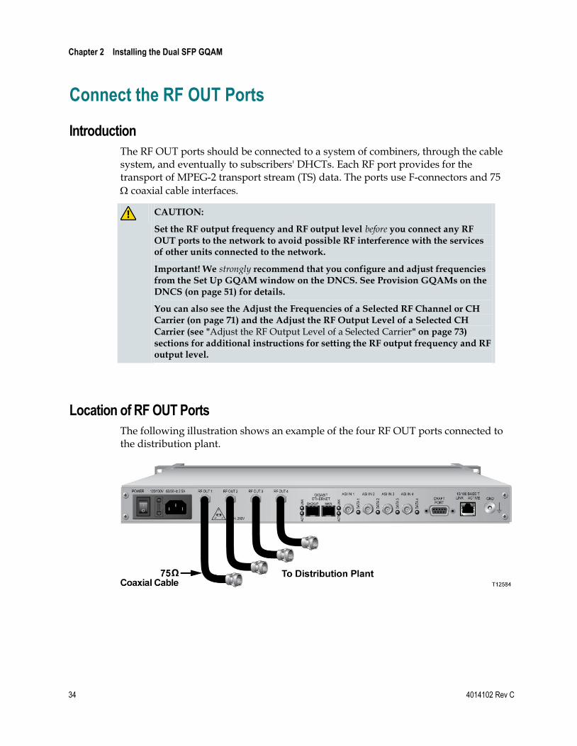
Location of RF OUT Ports
The following illustration shows an example of the four RF OUT ports connected to the distribution plant.

Connect the RF OUT Ports
4014102 Rev C 35
Connecting the RF OUT Ports
CAUTION:
Establish the RF output level before you connect the RF OUT ports to the distribution plant.
Important! We strongly recommend that you configure and adjust frequencies from the Set Up GQAM window on the DNCS. See the Provision GQAMs on the DNCS (on page 51).
You can also see the Mute the RF Output of a Selected CH Carrier (on page 74)
and the Adjust the RF Output Level of a Selected CH Carrier (see "Adjust the RF Output Level of a Selected Carrier" on page 73) sections for additional instructions for instructions on enabling the RF muting and setting the RF output level from the front panel of the GQAM.
1 Refer to your Network Wiring Diagram to connect the GQAM properly.
2 Locate the RF OUT ports on the back panel of the modulator.
3 Connect one end of a 75 coaxial cable to each RF OUT port to be used for the GQAM.
4 Verify that you have established the correct output level for the RF OUT port by completing the following steps:
a Connect one of the RF OUT ports on the GQAM to a spectrum analyzer to monitor one of the four frequencies on that port.
b Monitor the RF level for the selected frequency.
c Adjust the RF output level from the front panel of the modulator.
Important! RF plant balancing is normally done at the set-top.
d Provision the GQAM from the DNCS.
Note: Refer to Adjust the RF Output Level of a Selected CH Carrier (see "Adjust the RF Output Level of a Selected Carrier" on page 73) and to Provision GQAMs on the DNCS (on page 51) for more information.
e Connect the other end of each 75 coaxial cable to the distribution plant.


4014102 Rev C 37
Introduction
This chapter provides examples and descriptions of the DNCS graphical user interfaces (GUIs) used for provisioning (configuring) the Dual SFP GQAM as a DBDS network element from the DNCS. Provisioning the modulator allows the DNCS to recognize it and enables the modulator to operate properly. This chapter also provides procedures for adding service groups.
Important! Your system must be operating SR 2.7/3.7 or SR 4.2 (or later) to provision a Dual SFP GQAM on your system.
Note: See Technical Specifications (on page 111) and consult your network wiring diagram to ensure a proper allocation of bandwidth.
For more information about the DNCS and operating the DNCS software, refer to the Digital Network Control System Online Help.
3 Chapter 3 Provisioning the Dual SFP GQAM
In This Chapter
Understand the GUIs ........................................................................... 38
Provision GQAMs on the DNCS ........................................................ 51
Add a Service Group ............................................................................ 56

Chapter 3 Provisioning the Dual SFP GQAM
38 4014102 Rev C
Understand the GUIs
Introduction
This section provides examples and descriptions of the GUIs used for provisioning the GQAM as a DBDS network element from the DNCS.
Important! Actual GUIs may differ slightly from the GUIs presented in this guide.
Understanding the GUIs
Use the DNCS GUIs to provision the GQAM on the DNCS. The main GUI is the Set Up GQAM window which contains the following fields:
Basic Parameters
Advanced Parameters
Connectivity
Note: This section includes examples and descriptions of all of the areas within these fields.
Understanding Basic Parameters
The Basic Parameters fields allow you to identify the modulator, assign it to a headend, and specify the modulation type for each RF OUT port. If you want to view the Basic Parameters fields while reading this section, follow these steps to examine the Set Up GQAM window.
1 On the DNCS Administrative Console, select the DNCS tab, choose the Element Provisioning tab, and then click QAM. The QAM List window opens.

Understand the GUIs
4014102 Rev C 39
2 From the File menu, choose New and select GQAM. The Set Up GQAM window opens with the Basic Parameters tab to the forefront and displays the Basic Parameters fields as shown in the following example.
Basic Parameters
The following table lists the Basic Parameters fields and their descriptions.
Field Description
Headend Name Displays the name of the headend with which the modulator is associated
QAM Name Displays the name used for the modulator
IP Address Displays the IP address of the Ethernet interface through which the DNCS manages and controls the modulator
Modulation Type Allows you to specify one of the following modulation types for each of the carriers:
ITU J.83 Annex B (6 MHz)
ITU J.83 Annex C DAVIC/DVB (6 MHz)
Note: The default value is ITU J.83 Annex B (6 MHz).

Chapter 3 Provisioning the Dual SFP GQAM
40 4014102 Rev C
Administrative State Specifies whether the modulator is active within the system. The values are:
Offline: Default
Online: Active
MAC Address Displays the MAC address of the GQAM
Subnet Mask Displays the IP subnet mask assigned by the system administrator
Default Gateway Displays the network default gateway assigned by the system administrator
ASI Input Ports
The following table lists the ASI Input Ports fields and their descriptions.
Field Description
ASI 1 Transport Stream ID Displays the identifier of the MPEG transport stream generated upstream of the modulator. A unique value is assigned to the ASI IN 1 port.
Note: These modulators only accept DVB-ASI input, except at the GbE interfaces.
ASI 2 Transport Stream ID Displays the identifier of the MPEG transport stream generated upstream of the modulator. A unique value is assigned to the ASI IN 2.
Note: These modulators only accept DVB-ASI input, except at the GbE interfaces.
ASI 3 Transport Stream ID Displays the identifier for the MPEG transport stream generated upstream of the modulator. A unique value is assigned to the ASI IN 3 port.
Note: These modulators only accept DVB-ASI input, except at the GbE interfaces.
ASI 4 Transport Stream ID Displays the identifier for the MPEG transport stream generated upstream of the modulator. A unique value is assigned to the ASI IN 4 port.
Note: These modulators only accept DVB-ASI input, except at the GbE interfaces.
Gigabit Ethernet Ports
The following table lists the Gigabit Ethernet Ports fields and their descriptions.
Understand the GUIs
4014102 Rev C 41
Field Description
Dual GbE Port Allows you to enable the dual GbE port feature
Provision Dual GbE Select to turn on all options for provisioning GbE ports
Switch Mode Allows you to define how the GQAM will switch from one GbE port to the other GbE port. Select one of the following modes:
Auto: Select to switch from the active GbE port to the inactive GbE port when the modulator detects a loss of signal on the active port that meets or exceeds the Los timer.
Manual: Select to force to use a specific GbE port. This is typically used for maintenance or troubleshooting.
Initial Port Allows you to select the port to use during boot up. Select one of the following ports:
First
Second
Los Timer (Los of Signal Timer) Allows you to define the length of time (in milliseconds) that the modulator will wait before switching from the active GbE port to the inactive GbE port
Status Clicking Status displays the GbE port that is currently active, along with the current date and time. Port 5 indicates the main GbE port is active; port 6 indicates the backup GbE port is active
IP Address Displays the IP address for the main GbE port
Subnet Mask Displays the subnet mask for the main GbE port
Physical Address Displays the MAC address of the GbE port
Second Port IP Address Displays the IP address for the backup GbE port
Second Port Subnet Mask Displays the subnet mask for the backup GbE port
Second Port Physical Address
Displays the MAC address of the backup GbE port
RF OUT Parameters
The following table lists the RF OUT module (1–4) fields and their descriptions.
Field Description
Modulation Displays the modulation format of the individual carriers. The default is 256-QAM for ITU J.83 Annex B.

Chapter 3 Provisioning the Dual SFP GQAM
42 4014102 Rev C
Transport Stream ID Displays the identifier of the transport stream ID for each RF OUT module
Channel Center Frequency (MHz)
Displays the frequency assigned to each carrier (range is 91 MHz to 869 MHz). Valid frequencies use the following format, with XXX representing a number from 91 to 869.
XXX.000
XXX.25
XXX.75
Continuous Wave Mode Provides an unmodulated RF carrier
Note: Continuous wave mode may be selected for each carrier.
Mute RF Output Disables the RF output. May be selected for each carrier.
Disabled Prevents the DNCS from setting up any additional sessions on this RF output if the DNCS is choosing QAM resources. Existing sessions are not affected and continue to function as expected. May be selected for each RF output.
Interleaver Depth Allows you to select the Interleave setting based on the type of set-top you are using on your system. Interleaving is a technique to overcome correlated channel noise. Interleaving spreads out bursts of errors to remain within the error-correcting ability of a device.
Port to Hubs Allows you to define which hubs will receive program or service data from the RF output carrier
Application Support Allows you to define one of the following applications that each RF output carrier provides:
Shared: Select when the RF carrier is used for VOD, SDV, and broadcast sessions
VOD only: Select when the RF carrier is used only for VOD sessions
SDV only: Select when the RF carrier is used only for SDV sessions
Broadcast only: Select when the RF carrier is used only for broadcast sessions
Function Keys
The following function keys appear on the Set Up GQAM window.

Understand the GUIs
4014102 Rev C 43
Key Function
Save Saves changes to settings and closes the Set Up GQAM window
Apply Makes changes to settings without closing the Set Up GQAM window
Cancel Closes the Set Up GQAM window without saving changes that have not been previously applied to settings
Help Opens the DNCS Online Help
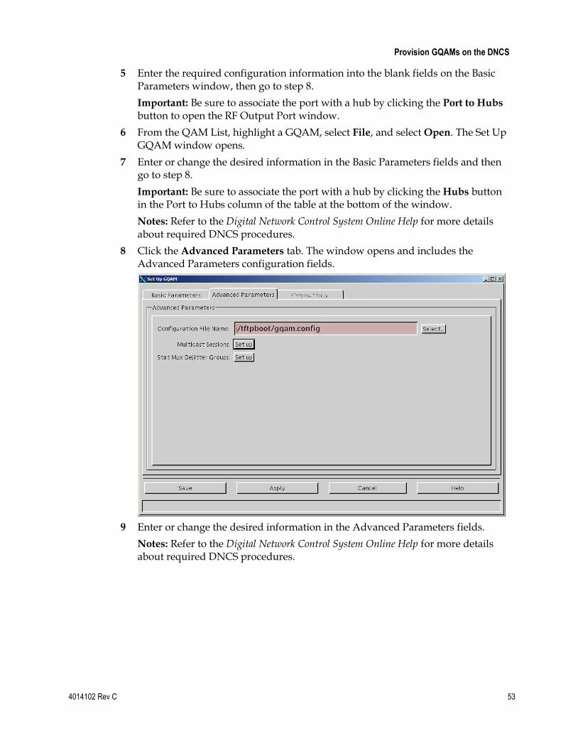
Understanding Advanced Features
The Advanced Parameters fields allow you to select the configuration file and to set up a multicast session or stat mux dejitter groups (SMDGs). To view the Advanced Parameters fields, click the Advanced Parameters tab in the Set Up GQAM window.
The following diagram shows an example of the Advanced Parameters fields.
Important! Unless you are setting up multicast sessions or setting up SMDG on this modulator, you should not use the Advanced Parameters tab because the system automatically selects the appropriate configuration file for you. This file tells the modulator which version of software to use. Unless you are setting up multicast sessions or SMDGs, do not change information in this window without direction from Cisco Service.

Chapter 3 Provisioning the Dual SFP GQAM
44 4014102 Rev C
Advanced Parameters
The following table lists Advanced Parameters field descriptions.
Field Description
Configuration File Name Displays the name of the configuration file used by the GQAM to determine whether it is running the correct version of application code
Multicast Sessions Allows you to setup multicast sessions on a GQAM modulator and on any SMDG that has been set up for a GQAM modulator
Stat Mux Dejitter Groups Allows you to set up SMDGs on modulators that receive multiplexed sources. You can set up a maximum of 16 SMDGs
Function Keys
The following additional function keys appear in the Advanced Parameters window.
Key Function
Select Opens the File Selection Dialog window so that you can specify the configuration file for the selected modulator. Refer to Understanding the File Selection Dialog Screen (on page 44) for more details.
Set up Opens the Multiple Digital Session Definition for
GQAM window or the Stat Mux Dejitter Groups For
GQAM window, respectively.
Understanding the File Selection Dialog Screen
The File Selection Dialog Screen allows you to specify the configuration file for the modulator. To view the File Selection Dialog screen, click the Select button on the Advanced Parameters tab on the DNCS GUI.
Understanding the Bootp/Tftp Process
When a modulator boots, it sends a bootp request to get an IP address. The bootp/tftp process allows the GQAM, after power on or reset, to request and receive configuration parameters, application downloads, and provisioning from the network bootp server. The DNCS, which is a bootp server, uses a bootp reply to assign an IP address to the GQAM, provided the device is provisioned in the DNCS database. The configuration file selected in the File Selection Dialog window is included in the bootp reply.
Understand the GUIs
4014102 Rev C 45
The GQAM uses the information in the configuration file to determine whether it is running the correct version of application code. If it is not running the correct version of application code, it requests the correct image file(s) from the DNCS.
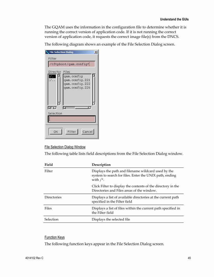
The following diagram shows an example of the File Selection Dialog screen.
File Selection Dialog Window
The following table lists field descriptions from the File Selection Dialog window.
Field Description
Filter Displays the path and filename wildcard used by the system to search for files. Enter the UNIX path, ending with /*.
Click Filter to display the contents of the directory in the Directories and Files areas of the window.
Directories Displays a list of available directories at the current path specified in the Filter field
Files Displays a list of files within the current path specified in the Filter field
Selection Displays the selected file
Function Keys
The following function keys appear in the File Selection Dialog screen.

Chapter 3 Provisioning the Dual SFP GQAM
46 4014102 Rev C
Key Function
OK Places the selected file name into the Configuration File Name field and closes the File Selection Dialog window
Filter Enables the contents of the directory to display in the Directories and Files areas
Cancel Closes the File Selection Dialog window without changing the original settings
Understanding the Multicast Digital Session Definition for GQAM Window
The Multicast Digital Session Definition window allows you to set up multicast sessions on a GQAM modulator and on any SMDGs that have been set up for the modulator. To view this window while reading this section, click the Set up button next to Multicast Sessions on the Advanced Parameters tab.
The following diagram shows an example of the Multicast Digital Session Definition for Gqam window.
Notes:
If you are using a GQAM modulator to send multicast sessions to the network and you have already added it to the DNCS and have created a source for the session, you can set up multicast sessions.
If you are using a GQAM modulator that receives input from a statistical multiplexor (stat mux) to send multicast sessions to the network, have already added SMDGs to the DNCS, and have created a source for the session, you can set up multicast sessions on the GQAM SMDGs. You can set up a maximum of 60 sessions on an SMDG.

Understand the GUIs
4014102 Rev C 47
Multicast Digital Session Definition for GQAM Window
The following table lists field descriptions on the Multicast Digital Session Definition for GQAM window.
Field Description
Select Displays whether or not a session is selected in the current window
Source ID Displays the source ID that this session is using
Session ID Displays the session ID that this session is using
Bandwidth Displays the amount of bandwidth (in Mbps) that the system should allow for this service
Program Number Displays the MPEG program number being fed into the transport stream
Source IP Address 1 Displays the IP address of the first source device
Source IP Address 2 Displays the IP address of the second source device (if used)
Source IP Address 3 Displays the IP address of the third source device (if used)
Destination Multicast IP Address
Displays the multicast IP address on the modulators where sources are input
Out RF Carrier Displays the output destination of the source
Function Keys
The following function keys appear in the Multicast Digital Session Definition for GQAM window.
Key Function
New Allows you to define a new multicast session
Tear Down Selected Session
Allows you to tear down or delete a selected multicast session
Exit Closes the Multicast Digital Session Definition for GQAM window
Help Accesses context-sensitive help

Chapter 3 Provisioning the Dual SFP GQAM
48 4014102 Rev C
Understanding the Stat Mux Dejitter Groups For GQAM Window
The Stat Mux Dejitter Groups For GQAM window allows you to set up stat mux dejitter groups (SMDGs) on GQAM modulators that receive multiplexed sources. SMDGs identify each GQAM input and output that will carry the multiplexed source and they also allow the modulator to appropriately process the multiplexed sources. After setting up SMDGs, you can set up sessions for groups to carry. To view this window while reading this section, click the Select button next to the Stat Mux Dejitter Groups button on the Advanced Parameters tab.
Important! Setting up an SMDG enables the modulator to appropriately process multiplexed sources. Failing to set up SMDGs on GQAM modulators that receive multiplexed sources may result in tiling of the video on DHCTs.
The following diagram shows an example of the Stat Mux Dejitter Groups For GQAM window.
Stat Mux Dejitter Groups For GQAM Window
The following table lists field descriptions on the Stat Mux Dejitter Groups For GQAM window.
Field Description
ID Displays an identifier (numerical value between 1 and 65535) to indicate the SMDG
Bandwidth Displays the bandwidth that the modulator will use
Input Port Displays the input port that the SMDG uses
Destination IP Address Displays the IP address for the GQAM modulator that receives the multiplexed source
Note: If an ASI port receives the source, this field will be empty.

Understand the GUIs
4014102 Rev C 49
Destination UDP Port Displays the UDP port on the GQAM modulator that receives the multiplexed source
Note: If an ASI port receives the source, this field will be empty.
Output Port Displays the output port that the SMDG is using
Function Keys
The following function keys appear in the Stat Mux Dejitter Groups For GQAM window.
Key Function
New Allows you to define a new SMDG
Delete Allows you to delete a selected SMDG session
Exit Closes the Stat Mux Dejitter For GQAM window
Help Accesses context-sensitive help
Understanding Connectivity
The Connectivity fields of the Set Up GQAM window allow you to specify the input device connected to each of the input ports on the GQAM.
Note: When you first provision the GQAM, the Connectivity fields are accessible only after you click Apply or Save from the Set Up GQAM window.
To view the Connectivity fields while reading this section, click the Connectivity tab in the Set Up GQAM window.
The following diagram shows an example of the Connectivity fields within the window.

Chapter 3 Provisioning the Dual SFP GQAM
50 4014102 Rev C
Connectivity
The following table lists the Connectivity field descriptions.
Field Description
QAM Name Identifies the name of the selected modulator and allows you to specify the input port (ASI or GbE)
Headend Name Identifies the headend in which the input device exists
Device Type Identifies the type of input device, such as an SDV server, VOD server, xOD server, SONET to ASI converter, or BIG to which the modulator is connected
Device Name Identifies the name of the input device to which the modulator is connected
Port Number Identifies the port number of the device that is connected to the GQAM. The server should be entered as the DNCS as a generic MPEG source. Create as many ports as are available for the server and connect to the modulator
Show TSIDs/IPs Displays the Transport Stream (TS) IDs and Internet Protocol addresses (IPs)
Show (slot, port) Displays the slot and port of the card connected to the modulator
Legend Displays a group of icons that represent network elements that may be displayed in the graphical drawing area

Provision GQAMs on the DNCS
4014102 Rev C 51
Provision GQAMs on the DNCS
Introduction
In order for the GQAM to operate properly as a network element within the DBDS, you must provision it on the DNCS. This section provides procedures for provisioning a GQAM on the DNCS.
Provisioning the Modulator on the DNCS 1 Verify that you have provisioned the GQAM in accordance with your network
wiring diagram, along with the Technical Specifications (on page 111) and other network devices.
To provision the GQAM on the DNCS, the system administrator must do the following.
a Enter the IP and physical (MAC) addresses of the GQAM.
b Assign a name to the GQAM.
c Associate the GQAM with a headend.
d Set the RF frequencies for each output port.
e Associate ports to hubs.
f Select a modulation type.
g Select transport stream IDs.
h Configure continuous wave mode.
i Configure the Mute RF settings.
j Define MPEG sources.
k Add Service Groups, as needed.
l Assign the GbE ports.
Note: Refer to the Digital Network Control System Online Help for more information about provisioning network elements.

Chapter 3 Provisioning the Dual SFP GQAM
52 4014102 Rev C
2 From the DNCS Administrative Console, select the DNCS tab, click the Network
Element Provisioning tab, and then click QAM. The QAM List window opens.
3 Choose one of the following options:
To provision a new modulator, go to step 4.
To change the settings for an existing modulator, go to step 6.
4 From the File menu, click New and select GQAM. The Set Up GQAM window opens.
Provision GQAMs on the DNCS
4014102 Rev C 53
5 Enter the required configuration information into the blank fields on the Basic Parameters window, then go to step 8.
Important: Be sure to associate the port with a hub by clicking the Port to Hubs button to open the RF Output Port window.
6 From the QAM List, highlight a GQAM, select File, and select Open. The Set Up GQAM window opens.
7 Enter or change the desired information in the Basic Parameters fields and then go to step 8.
Important: Be sure to associate the port with a hub by clicking the Hubs button in the Port to Hubs column of the table at the bottom of the window.
Notes: Refer to the Digital Network Control System Online Help for more details about required DNCS procedures.
8 Click the Advanced Parameters tab. The window opens and includes the Advanced Parameters configuration fields.
9 Enter or change the desired information in the Advanced Parameters fields.
Notes: Refer to the Digital Network Control System Online Help for more details about required DNCS procedures.

Chapter 3 Provisioning the Dual SFP GQAM
54 4014102 Rev C
10 To define the Configuration File Name, click Select. The File Selection Dialog window opens.
11 Enter the configuration file in the Selection field and click OK. The File Selection Dialog window closes.
12 Choose one of the following options:
To adjust the connectivity settings for an existing modulator, go to step 13.
To provision the connectivity settings for a new modulator, click Apply.
Note: When you first provision a modulator, the Connectivity tab is accessible only after you click Apply or Save.
13 Are you setting up multicast sessions?
If yes, click the Setup appropriate button and create a new Multicast Digital Session definition. Then refer to the Digital Network Control System Online Help for a step-by-step procedure.
If no, go to step 14.
14 Are you setting up Stat Mux Dejitter Groups?
If yes, click the appropriate Set up button and create a new stat mux dejitter group definition. Then refer to the Digital Network Control System Online Help for a step-by-step procedure.
If no, go to step 15.

Provision GQAMs on the DNCS
4014102 Rev C 55
15 Click the Connectivity tab. The window opens and includes the Connectivity configuration fields.
16 Select the port you want to connect to the network.
17 Select the appropriate device you want to connect to in the Connect To area and then click Save. The QAM List is updated.
Notes:
The fields available in the Connect To panel of the Connectivity tab vary according to which device is selected.
Refer to the Digital Network Control System Online Help for more details about required DNCS procedures.
18 Go to Add a Service Group (on page 56).
Chapter 3 Provisioning the Dual SFP GQAM
56 4014102 Rev C
Add a Service Group
Introduction
If you are going to provide VOD, xOD, or SDV services, you must add a service group for each VOD, xOD, or SDV server in your network, along with the associated GQAMs. A service group is a set of GQAM modulator channels that have been combined to provide narrowcast services (VOD, xOD, or SDV) to a unique group of DHCTs. Service groups enable DHCTs to distinguish which GQAM is providing which service.
You can create the following types of service groups:
Parent service groups: service groups which contain one or more child service groups
Child service groups: service groups which belong to a parent service group
Standalone service groups: service groups which are independent; they contain no child service groups nor do they belong to a parent service group
Note: Allowing one service group to belong to another enables you to more effectively manage the different types of content that a server provides.
Before You Begin
Before you begin, you must have your network map. If you cannot locate your network map, contact Cisco Services. You must also know which GQAM will be providing data for each VOD, xOD, or SDV service.
Adding a Service Group 1 From the DNCS Administrative Console, click the DNCS tab.

Add a Service Group
4014102 Rev C 57
2 Click the Network Element Provisioning tab and then click Service Group. The Service Group Data window opens.
Note: The SDV column only displays if SDV services are enabled for your system.
3 Click Add Service Group. The Add Service Group table opens.
4 Click in the ID field and enter a unique number to identify the service group.
Chapter 3 Provisioning the Dual SFP GQAM
58 4014102 Rev C
Important! Make certain that this field contains only numerical characters and that the field contains no leading spaces. Entering alphabetical characters or a leading space in this field can cause the service group and associated resources assigned to the service group to become non-editable or non-viewable.
5 Click in the Name field and enter a name for the service group.
Note: You can use numbers and letters. Cisco recommends that you establish a naming scheme that allows you to easily identify the service or modulator providing it, and which hub they serve.
Example: A name of VOD_SG_Hub1_GQ43 could represent a VOD service group associated with an GQAM modulator, whose IP address ends in 43, and that processes VOD data for Hub 1.
6 What kind of service group are you creating?
If a parent service group, select the Is Parent Group check box. Then go to step 7.
If a standalone or a child service group, go to step 9.
Note: You must create a parent group before you are create a child service group.
7 In the Available Group list, click to select a group that will be a child to this parent group and then click Add. The selected group moves from the Available Group list into the Selected Child list.
Note: You can also remove child groups by selecting the name of the group you want to remove in the Selected Child list and clicking Remove.
8 Repeat step 7 for each group that will be a child to this service group.
9 In the Available Ports list, click to select the port of the modulator that will be providing data for this service group and then click Add. The selected port moves from the Available Ports list into the Selected Ports list.
Note: You can remove ports by selecting the name of the port you want to remove in the Selected Ports list and clicking Remove.
10 Is the service group for SDV services?
If yes, select the SDV Enabled check box and then refer to Provisioning the DNCS to Support SDV Services User Guide for details on creating a service group for SDV services.
If no, go to step 11.
Note: The SDV Enabled option only displays if SDV services are enabled for your system.
11 Click Save Service Group. The system closes the Add Service Group table and displays the Service Group Data window, which now lists the service group that you just added.
12 Add the new service group to your network map as specified in the Client Configuration Management (CCM) process.

Add a Service Group
4014102 Rev C 59
Note: The CCM Process helps keep Cisco informed of network changes as you make them. This allows us to help troubleshoot your system more effectively and efficiently should the need arise. If you are not familiar with the CCM process, contact Cisco Services immediately for further assistance.
13 Do you need to add another service group?
If yes, repeat steps 3 through 12.
If no, click Exit to close the Service Group Data window and return to the DNCS Administrative Console.
14 Are you setting up your network for the first time?
If yes, go to step 15.
If no, continue making any other changes that you need to make to your network. When finished, send a copy of your updated network map to Cisco as specified in the CCM process. Then go to step 17.
15 Are you using SONET interfaces in your network?
If yes, go to Setting Up SONET topic in the DNCS help. Then return to this procedure and continue with step 16.
If no, go to step 16.
16 Does your network comply with OpenCable standards?
If yes, go to Setting up OpenCable Compliance topic in the DNCS help. Then return to this procedure and continue with step
If no, continue making any other changes that you need to make to your network. When finished, send a copy of your updated network map to Cisco as specified in the CCM process. Then go to step 17.
17 When provisioning is complete, power on the GQAM.
18 After the modulator boots, click Element Provisioning on the DNCS Administrative Console.
19 Click QAM and select the modulator you just added.
20 From the File menu, click Open. The Set Up GQAM window opens.
21 From the Basic Parameters area, verify that the Administrative State for the new GQAM is set to Online.


4014102 Rev C 61
Introduction
This chapter contains procedures for viewing and changing GQAM settings, descriptions of screens and messages, and instructions for performing routine maintenance.
Note: Actual screen settings may differ slightly from the examples presented in this guide.
4 Chapter 4 Operating the Modulator
In This Chapter
Understand the Boot Process .............................................................. 62
Change the Boot Mode ......................................................................... 65
Read the Default Status Screen ........................................................... 67
Use the Front Panel Keys to Change Configuration Settings ......... 68
Adjust the Frequencies of a Selected RF Channel or CH Carrier ..................................................................................................... 71
Adjust the RF Output Level of a Selected Carrier ............................ 73
Mute the RF Output of a Selected CH Carrier .................................. 74
Change the Carrier Mode of a Selected CH Carrier......................... 75
Monitor Setup Options ........................................................................ 76
Inspect the Modulator .......................................................................... 85
Replace the Fuse .................................................................................... 86
Diagnose the Fan ................................................................................... 88
Replace the Fan ..................................................................................... 90

Chapter 4 Operating the Modulator
62 4014102 Rev C
Understand the Boot Process
Introduction
This section describes the boot process and lists examples of the screens that appear during a normal boot process. The Bootstrap (BOOTP) protocol is used to initialize and to acquire the following configuration information:
IP address
Address mask
Location of default gateway
Addresses of important servers
Name and location of software download file(s) from the network BOOTP server
Note: The GQAM downloads software using Trivial File Transfer Protocol (TFTP), which is a simplified version of FTP.
See Change the Boot Mode (on page 65) for a description of the boot modes available and instructions for changing the boot mode.
See Troubleshooting Boot Screen Error Messages (on page 104) for troubleshooting booting conditions.
Boot Process 1 The GQAM sends a BOOTP request to the DNCS.
2 The DNCS responds to the BOOTP request, sending the IP address for the GQAM.
3 The GQAM sends a TFTP request for the configuration file.
Note: The configuration file (gqam.config) contains environment variables, download files, and server addresses.
4 The DNCS sends the TFTP gqam.config file.
5 If the files in the gqam.config file are different from those stored in the GQAM, then the GQAM requests the download files, which consist of the following:
Boot code for Host, NP1, NP2, and NP3
Application code for Host, NP1, NP2, and NP3
RF module code for RF Modules 1, 2, 3, and 4
Note: The messages that appear on the front panel of the GQAM during the boot process are described in Initial Boot Screens (on page 63) and Code Download Screens (on page 63).
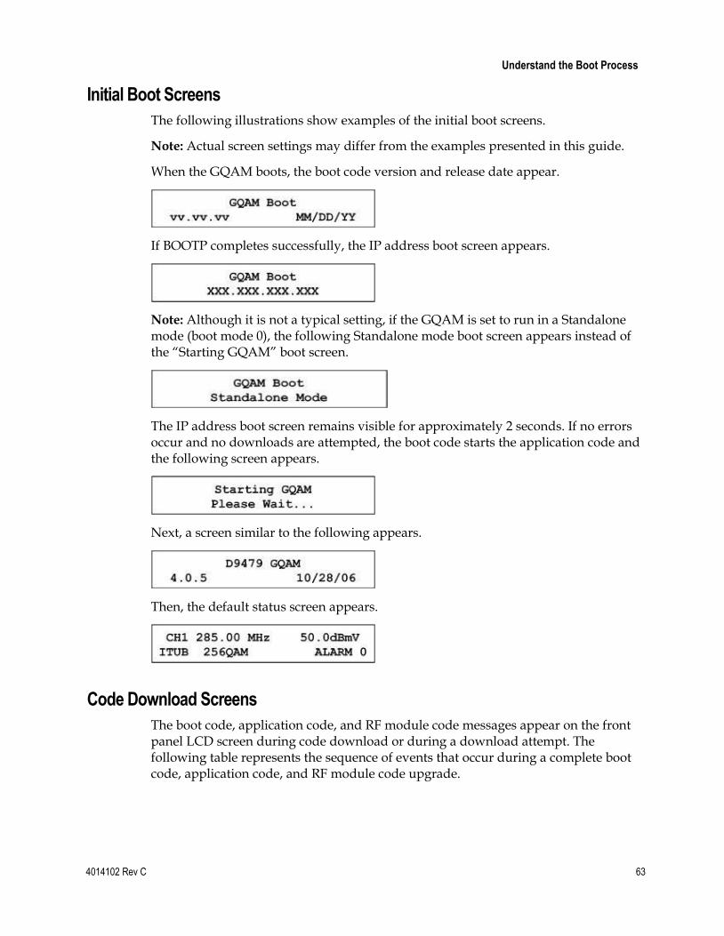
Understand the Boot Process
4014102 Rev C 63
Initial Boot Screens
The following illustrations show examples of the initial boot screens.
Note: Actual screen settings may differ from the examples presented in this guide.
When the GQAM boots, the boot code version and release date appear.
If BOOTP completes successfully, the IP address boot screen appears.
Note: Although it is not a typical setting, if the GQAM is set to run in a Standalone mode (boot mode 0), the following Standalone mode boot screen appears instead of the “Starting GQAM” boot screen.
The IP address boot screen remains visible for approximately 2 seconds. If no errors occur and no downloads are attempted, the boot code starts the application code and the following screen appears.
Next, a screen similar to the following appears.
Then, the default status screen appears.
Code Download Screens
The boot code, application code, and RF module code messages appear on the front panel LCD screen during code download or during a download attempt. The following table represents the sequence of events that occur during a complete boot code, application code, and RF module code upgrade.

Chapter 4 Operating the Modulator
64 4014102 Rev C
Code Type Front Panel Screen Message
Initial Boot
GQAM Boot vv.vv.vv MM/DD/YY
GQAM Boot xxx.xxx.xxx.xxx
Host Processor Boot Code
Downloading Host Code !!! Do Not Power Off !!!
GQAM Boot vv.vv.vv MM/DD/YY
GQAM Boot xxx.xxx.xxx.xxx
Host Processor Application Code
Downloading Host Code Please Wait ….
Writing App Code Flash Please Wait ….
RF Code Downloading RF # Code Please Wait …. (where # = 1-4)
Input Processor Boot Code Downloading NP1 Code Please Wait ….
Output Processor 1 & 2 Boot Code
Downloading NP2&3 Code Please Wait ….
GQAM Boot vv.vv.vv MM/DD/YY
GQAM Boot xxx.xxx.xxx.xxx
Input Processor Application Code Downloading NP1 Code Please Wait ….
Output Processor 1 & 2 Application Code
Downloading NP2&3 Code Please Wait ….
Starting GQAM Please Wait….
(a blank screen appears momentarily)
D9479 GQAM vv.vv.vv MM/DD/YY
When the code download is complete, the default status screen appears.
CH 1 300.00 MHz 50.0 dBmV ITUB 256QAM Alarm 0

Change the Boot Mode
4014102 Rev C 65
Change the Boot Mode
Introduction
This section describes the available boot modes available and contains instructions for changing the boot mode from the craft port using a diagnostic PC.
Boot Modes
Three boot modes (0 through 2) exist and are described in the following list:
0 - Skip BootP (Standalone mode) – This mode bypasses the boot mode when you power on the GQAM. Use the Skip BootP mode when operating in Standalone mode, when provisioning and monitoring the GQAM from the front panel or the craft port, or when operating without the control of the DNCS. This mode skips the BOOTP and TFTP processes and jumps directly to the application code.
1 - Attempt BootP One Time (Attempt Bootp Once mode) – This mode is not normally used in network operation. If used when the GQAM is connected to the network and the network connection is lost or reset, the GQAM must be rebooted. This mode attempts each BOOTP and TFTP step only once. If a failure occurs during any step, the step is skipped; the GQAM attempts the remaining steps and eventually attempts to start the application. If the BOOTP and/or configuration file TFTP steps are aborted due to errors, the GQAM may not communicate with the DNCS.
2 - Bootp Until Successful (Boot Until Successful mode) – This is the default mode. This mode continues to boot until the GQAM receives an IP address and all download images. This setting is useful when upgrading the software. Booting until successful ensures that the GQAM completes all startup procedures successfully. Use the standard mode (boot forever until successful) when a network controller such as the DNCS monitors and provisions the GQAM through the Ethernet port. This mode attempts to boot and to TFTP the configuration file and any requested boot and/or application code files until the entire process is successful. If an error occurs at any step, the GQAM restarts until a successful boot occurs.
Important! Do not select this setting when operating the GQAM outside a DNCS environment.
Changing the Boot Mode 1 Connect a diagnostic PC to the CRAFT PORT on the back panel of the GQAM.
2 Power on the diagnostic PC and activate a Procomm or Hyperterminal window using the following modem connection settings:
Chapter 4 Operating the Modulator
66 4014102 Rev C
9600 baud
1 stop bit
No parity
8 data bits
No flow control
3 Power on the GQAM; then, during the boot sequence, watch for the following message on the PC monitor screen: Type any key within 2 seconds to get shell prompt
Note: See the Connect Power Sources (on page 26) section for more details about powering on the GQAM.
4 Press any key on the PC to display the boot prompt. The following boot prompt appears: boot>
Note: If you do not press a key in time to get the boot prompt, do one of the following:
Cycle power to the GQAM, and repeat this step. See Resetting the Modulator (on page 84) for more details.
At the GQAM> prompt, type boot; then, after the Type any key message appears, press any key to display the boot prompt.
5 At the boot prompt, type setbootmode and press Enter. The current boot mode setting appears.
6 Type one of the following numbers to select the boot mode:
0 - Skip BootP
1 - Attempt BootP One Time
2 - Bootp Until Successful
Result: The system saves the new boot mode to nonvolatile memory (NVRAM) with the new setting.
7 Type exit and press Enter. The GQAM reboots using the new boot mode.
8 Disconnect the diagnostic PC.
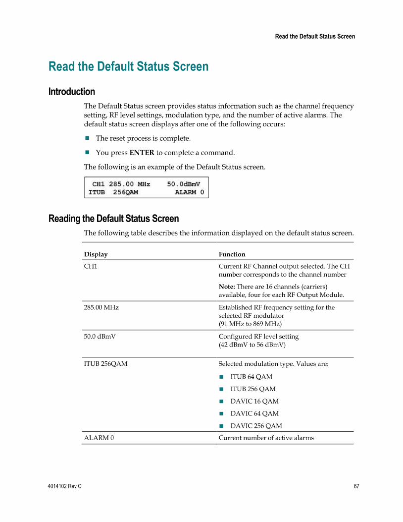
Read the Default Status Screen
4014102 Rev C 67
Read the Default Status Screen
Introduction
The Default Status screen provides status information such as the channel frequency setting, RF level settings, modulation type, and the number of active alarms. The default status screen displays after one of the following occurs:
The reset process is complete.
You press ENTER to complete a command.
The following is an example of the Default Status screen.
Reading the Default Status Screen
The following table describes the information displayed on the default status screen.
Display Function
CH1 Current RF Channel output selected. The CH number corresponds to the channel number
Note: There are 16 channels (carriers) available, four for each RF Output Module.
285.00 MHz Established RF frequency setting for the selected RF modulator (91 MHz to 869 MHz)
50.0 dBmV Configured RF level setting (42 dBmV to 56 dBmV)
ITUB 256QAM Selected modulation type. Values are:
ITUB 64 QAM
ITUB 256 QAM
DAVIC 16 QAM
DAVIC 64 QAM
DAVIC 256 QAM
ALARM 0 Current number of active alarms

Chapter 4 Operating the Modulator
68 4014102 Rev C
Use the Front Panel Keys to Change Configuration Settings
Introduction
The front panel of the GQAM contains an alphanumeric LCD screen and three alarm indicators. There are also several keys on the front panel to allow you to change parameters. See the Front Panel Overview (on page 7) section for more information on the front panel components.
Diagram of the Menu Structure
The following diagram illustrates the menu structure in sequential order.
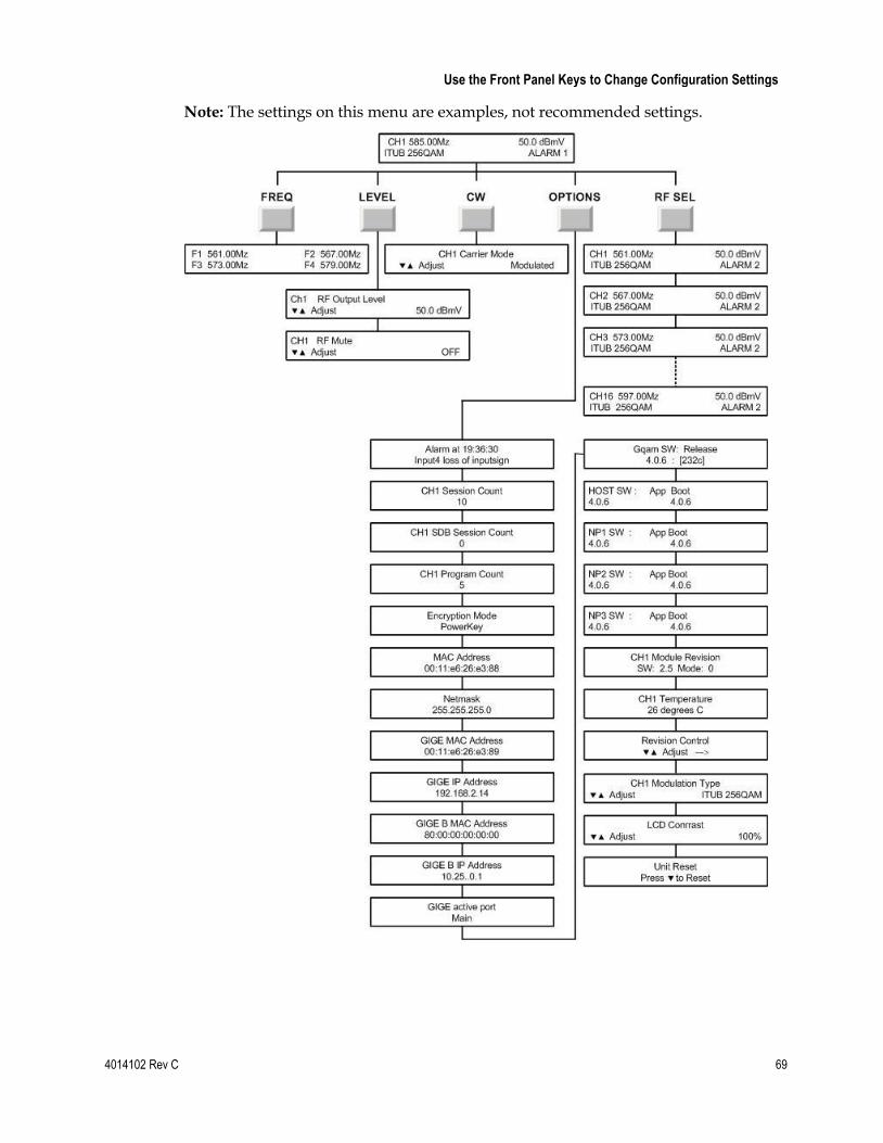
Use the Front Panel Keys to Change Configuration Settings
4014102 Rev C 69
Note: The settings on this menu are examples, not recommended settings.

Chapter 4 Operating the Modulator
70 4014102 Rev C
Accessing the Menus on the Modulator
You can access the menus and screens by pressing the FREQ, LEVEL, CW, and OPTIONS keys on the front panel of the modulator. Pressing these keys repeatedly scrolls through their respective sequential menus.
The following sections in this chapter describe the functions associated with each key:
FREQ – Adjust the Frequencies of a Selected RF Channel or CH Carrier (on page 71)
LEVEL
- Adjust the RF Output Level of a Selected CH Carrier (see "Adjust the RF Output Level of a Selected Carrier" on page 73)
- Mute the RF Output of a Selected CH Carrier (on page 74)
CW – Change the Carrier Mode of a Selected CH Carrier (on page 75)
OPTIONS – Monitor Setup Options (on page 76)
RF SEL – Adjust the Frequencies of a Selected RF Channel or CH Carrier (on page 71)
Note: See Front Panel Overview (on page 7) for detailed descriptions of these keys.
Navigating Within a Menu or Changing a Screen Value
The Up and Down arrow keys are used in conjunction with the other front panel keys to increment or decrement the values of a selected parameter within a screen or to scroll up and down through a set of selections.
Saving Changes to Configuration Settings
Pressing the Enter key saves changes to the configuration settings. You must also press the Enter key to return to the default status screen. Changes to any settings are saved into NVRAM. This memory is located on the digital board and is used to restore settings in the event of a power reset of the device.

Adjust the Frequencies of a Selected RF Channel or CH Carrier
4014102 Rev C 71
Adjust the Frequencies of a Selected RF Channel or CH Carrier
Introduction
Pressing the FREQ key allows you to access the output frequency screen, from which you can select an RF output group and adjust the individual carrier (CH) output frequency.
Important! Frequencies set from the front panel of the GQAM are not recorded by the DNCS. At the next modulator restart, the frequencies are reset to the values stored in the DNCS.
Example: A frequency setting of 285.00 Mz for F1 in the following illustration means that carrier channel 1 (CH1) has a frequency of 285.00 MHz. Each frequency setting also applies to a corresponding carrier channel.
Important! The frequencies within an RF output module group must be contiguous in 6 MHz increments, but the frequencies between groups do not have to be contiguous.
Example: RF2 can contain frequencies 309 MHz, 315 MHz, 321 MHz, and 327 MHz, and RF3 can begin at 381 MHz.
Adjusting the Output Frequency
Important! Frequencies set from the front panel of the GQAM are not recorded by the DNCS. At the next modulator restart, the frequencies are reset to the values stored in the DNCS.

Chapter 4 Operating the Modulator
72 4014102 Rev C
1 From the front panel of the modulator, press FREQ. A group of four output frequency settings appear with one of the frequency settings blinking. The setting that is blinking denotes the frequency of the selected channel.
Note: Each frequency setting (F1 through F4) reflects the channel number.
2 Press RF SEL to select a channel frequency setting.
Note: Press the RF SEL key repeatedly to view the RF output frequencies (F1 or F4).
3 Press the Up or Down Arrow keys to increase or decrease the output frequency value of a selected RF channel.
Notes:
The output frequency can be changed in 0.25 MHz increments from 91 MHz to 869 MHz. To increment or decrement the frequency value in 6 MHz steps, press and hold the Up or Down Arrow keys for about 2 seconds.
As a frequency value is incremented or decremented, the other frequencies within the RF Module are also adjusted. This is performed automatically to maintain the 6 MHz bandwidth between frequencies residing on the same RF output module.
4 Press ENTER. The system saves the output frequency changes to NVRAM and the default screen appears.
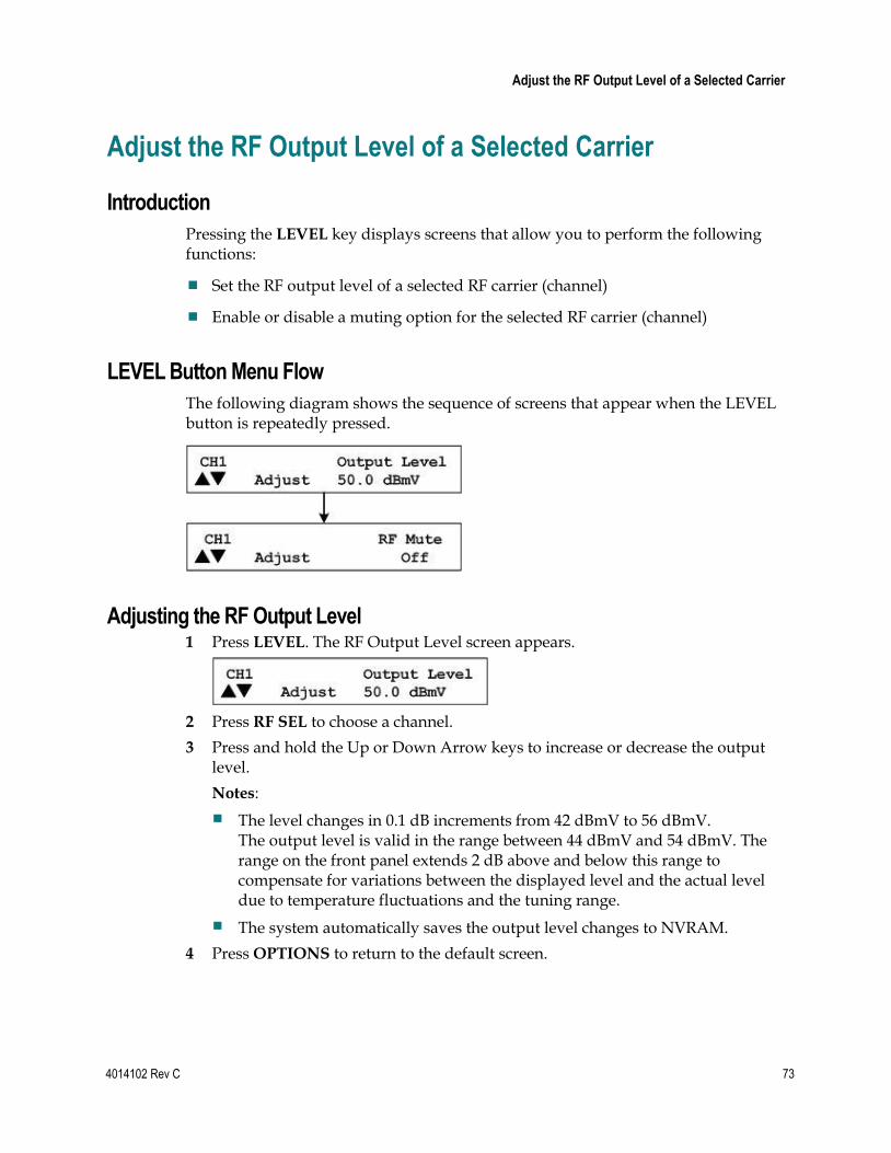
Adjust the RF Output Level of a Selected Carrier
4014102 Rev C 73
Adjust the RF Output Level of a Selected Carrier
Introduction
Pressing the LEVEL key displays screens that allow you to perform the following functions:
Set the RF output level of a selected RF carrier (channel)
Enable or disable a muting option for the selected RF carrier (channel)
LEVEL Button Menu Flow
The following diagram shows the sequence of screens that appear when the LEVEL button is repeatedly pressed.
Adjusting the RF Output Level 1 Press LEVEL. The RF Output Level screen appears.
2 Press RF SEL to choose a channel.
3 Press and hold the Up or Down Arrow keys to increase or decrease the output level.
Notes:
The level changes in 0.1 dB increments from 42 dBmV to 56 dBmV. The output level is valid in the range between 44 dBmV and 54 dBmV. The range on the front panel extends 2 dB above and below this range to compensate for variations between the displayed level and the actual level due to temperature fluctuations and the tuning range.
The system automatically saves the output level changes to NVRAM.
4 Press OPTIONS to return to the default screen.
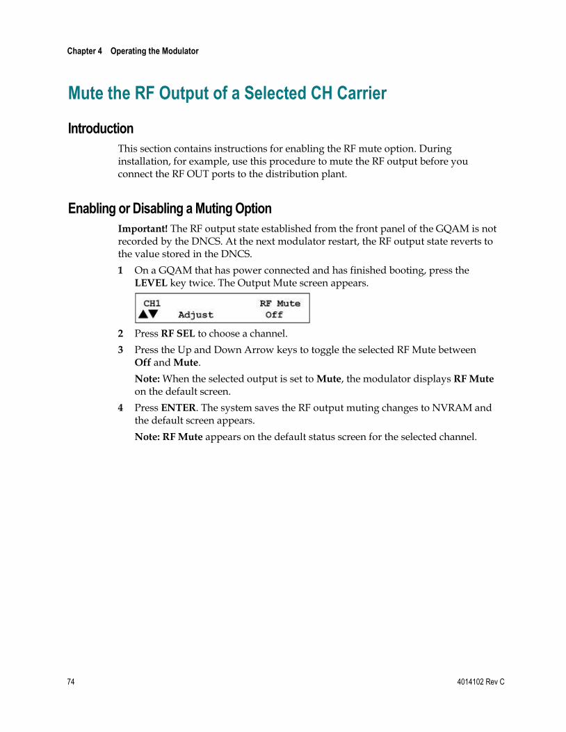
Chapter 4 Operating the Modulator
74 4014102 Rev C
Mute the RF Output of a Selected CH Carrier
Introduction
This section contains instructions for enabling the RF mute option. During installation, for example, use this procedure to mute the RF output before you connect the RF OUT ports to the distribution plant.
Enabling or Disabling a Muting Option
Important! The RF output state established from the front panel of the GQAM is not recorded by the DNCS. At the next modulator restart, the RF output state reverts to the value stored in the DNCS.
1 On a GQAM that has power connected and has finished booting, press the LEVEL key twice. The Output Mute screen appears.
2 Press RF SEL to choose a channel.
3 Press the Up and Down Arrow keys to toggle the selected RF Mute between Off and Mute.
Note: When the selected output is set to Mute, the modulator displays RF Mute on the default screen.
4 Press ENTER. The system saves the RF output muting changes to NVRAM and the default screen appears.
Note: RF Mute appears on the default status screen for the selected channel.

Change the Carrier Mode of a Selected CH Carrier
4014102 Rev C 75
Change the Carrier Mode of a Selected CH Carrier
Overview
This function allows you to toggle RF output to either a modulated (normal) carrier mode or a continuous wave (CW) carrier mode.
Important! The carrier mode established from the front panel of the modulator is not recorded by the DNCS. At the next GQAM restart, the carrier mode will revert to the value stored in the DNCS.
Selecting Modulated or Continuous Wave Carrier Mode 1 Press CW. The Carrier Mode screen appears.
2 Press RF SEL to choose a channel.
3 Press the Up and Down Arrow keys to toggle the carrier mode between Modulated (normal) and CW (not modulated or continuous wave).
Note: The factory default for the carrier mode setting is Modulated.
4 Press ENTER. The system saves the carrier mode setting changes to NVRAM and the default screen appears.
Note: When choosing CW mode, the CW LED on the front panel of the GQAM lights and CW appears on the default screen.

Chapter 4 Operating the Modulator
76 4014102 Rev C
Monitor Setup Options
OPTIONS Menu
The following setup screens appear, in sequential order, when you press the OPTIONS key repeatedly on the GQAM. These screens allow you to monitor alarms, as well as the session and program count. This section provides instructions for viewing each setting and provides explanations of screen information.
Important! The screens in the following diagram are examples, not recommended settings.

Monitor Setup Options
4014102 Rev C 77
Displaying Alarm Status 1 Press OPTIONS. The Alarm Status screen appears.
Notes:
Each alarm description appears for approximately 1 second before displaying the next alarm. If no alarms are active, a No Active Alarms message appears.
See Troubleshooting the GQAM (on page 93) for detailed descriptions of alarms.
2 Press ENTER. The default screen appears.
Viewing the Session Count
The Session Count screen displays the count of all active sessions for the selected RF output. Complete the following steps to view the total number of active sessions.
1 Press OPTIONS until the Session Count screen appears.
Note: The session count for the GQAM will differ from the session count on the DNCS if the GQAM does not find needed MPEG programs within MPEG Program Specific Information (PSI). By design, the GQAM responds positively to a session setup request even if the requested MPEG program is not present on the input transport stream.
2 Press RF SEL to view the session count for each channel.
3 Press ENTER to return to the default screen.
Viewing the SDB Session Count
The SDB Session Count screen displays the count of all active Switched Digital Video (SDV) sessions for the selected RF output. Complete the following steps to view the total number of active SDV sessions.
Note: SDB (Switched Digital Broadcast) and SDV are used interchangeably throughout this procedure.
1 Press OPTIONS until the SDB Session Count appears.
Note: If Switch Digital Video (SDV) is not configured on your system, the SDB session count will always be zero.
2 Press RF SEL to view the session count for each channel (CH1 or CH16).

Chapter 4 Operating the Modulator
78 4014102 Rev C
3 Press ENTER to return to the default screen.
Viewing the Program Count
The Program Count screen displays the encrypted programs currently running on the selected RF output. Complete the following steps to view the program count for an RF module.
1 Press OPTIONS until the Program Count screen appears.
2 Press RF SEL to view the program count for each channel.
3 Press ENTER to return to the default screen.
Viewing the Encryption Mode
The Encryption Mode screen displays the current encryption mode setting. The mode is saved in the NVRAM and is selected during the boot process. To display the current encryption mode, complete the following steps.
1 Press OPTIONS until the Encryption Mode screen appears.
2 Press ENTER to return to the default screen.
Viewing the MAC Address
To view the MAC address used for GQAM Ethernet communication, complete the following steps.
1 Press OPTIONS until the MAC Address screen appears.
2 Press ENTER to return to the default screen.
Viewing the Netmask Screen
To display the currently assigned Netmask for all Ethernet communications, complete the following steps.
1 Press OPTIONS until the Netmask screen appears.
2 Press ENTER to return to the default screen.

Monitor Setup Options
4014102 Rev C 79
Viewing the Gigabit MAC Address
To display the currently assigned Gigabit MAC address for the main port, complete the following steps.
1 Press OPTIONS until the Gigabit MAC address appears
2 Press Enter to return to the default screen.
Viewing the IP Address
To display the currently assigned IP address for all Ethernet communications, complete the following steps.
1 Press OPTIONS until the IP Address screen appears.
2 Press ENTER to return to the default screen.
Viewing the Backup MAC Address
To display the currently assigned Gigabit MAC address for the backup GbE port, complete the following steps.
1 Press OPTIONS until the GIGE B MAC Address appears.
2 Press Enter to return to the default screen.
Viewing the Backup IP Address
To display the currently assigned Gigabit IP address for the backup GbE port, complete the following steps.
1 Press OPTIONS until the GIGE B IP Address appears.
2 Press Enter to return to the default screen.

Chapter 4 Operating the Modulator
80 4014102 Rev C
Viewing the GIGE Active Port
To display the currently active GbE port, complete the following steps.
1 Press OPTIONS until the GIGE active port appears.
2 Press Enter to return to the default screen.
Viewing the GQAM Software Release
To display the current software release for the GQAM device, complete the following steps.
1 Press OPTIONS until the Gqam software release address appears:
2 Press Enter to return to the default screen.
Viewing the Host Software Revision Level
The Host Software Revision screen displays the revision level for the host processor in the GQAM. To display the Host Software Revision screen, complete the following steps.
1 Press OPTIONS until the Host Software Revision screen appears.
Notes:
In the above example, App is the application code and Boot is the boot code.
This revision number for the application code (4.0.5) and the boot code (4.0.5), represented in the above example, contains the major release number, minor release number, and the point release number.
Important! If an asterisk (*) appears after one of the code version numbers, this indicates that the code version is a mismatch to the GQAM software package version.
2 Press ENTER to return to the default screen.
Viewing the NP1 Software Revision Level
The NP1 software revision screen displays the revision level for the input processor in the GQAM. To display the NP1 software revision screen, complete the following steps.

Monitor Setup Options
4014102 Rev C 81
1 Press OPTIONS until the NP1 Software Revision screen appears.
Notes:
In the above example, App is the application code and Boot is the boot code.
This revision number for the application code (4.0.5) and the boot code (4.0.5), represented in the above example, contains the major release number, minor release number, and the point release number.
Important! If an asterisk (*) appears after one of the code version numbers, this indicates that the code version is a mismatch to the GQAM software package version.
2 Press ENTER to return to the default screen.
Viewing the NP2 Software Revision Level
The NP2 software revision screen displays the revision level for the Output 1 processor in the GQAM. To display the NP2 software revision screen, complete the following steps.
1 Press OPTIONS until the NP2 Software Revision screen appears.
Notes:
In the above example, App is the application code and Boot is the boot code.
This revision number for the application code (4.0.5) and the boot code (4.0.5), represented in the above example, contains the major release number, minor release number, and the point release number.
Important! If an asterisk (*) appears after one of the code version numbers, this indicates that the code version is a mismatch to the GQAM software package version.
2 Press ENTER to return to the default screen.
Viewing the NP3 Software Revision Level
The NP3 software revision screen displays the revision level for the Output 2 processor in the GQAM. To display the NP3 software revision screen, complete the following steps.
1 Press OPTIONS until the NP3 Software Revision screen appears.
Notes:

Chapter 4 Operating the Modulator
82 4014102 Rev C
In the above example, App is the application code and Boot is the boot code.
This revision number for the application code (4.0.5) and the boot code (4.0.5), represented in the above example, contains the major release number, minor release number, and the point release number.
Important! If an asterisk (*) appears after one of the code version numbers, this indicates that the code version is a mismatch to the GQAM software package version.
2 Press ENTER to return to the default screen.
Viewing the Module Revision Numbers
The Module Revision screen displays the revision numbers for the hardware and software of the selected RF channel. To display the Module Revision screen, complete the following steps.
1 Press OPTIONS until the Module Revision screen appears.
Notes:
SW shows the RF board microprocessor firmware revision displayed as major release and minor release.
If an asterisk (*) appears after one of the code version numbers, this indicates that the code version is a mismatch to the GQAM software package version.
Mode is the PWB assembly of configuration. The 0 indicates a Standard/Domestic Mode (Baseband to RF Output) PWB assembly.
2 Press RF SEL to display Module Revision information for each channel.
3 Press ENTER to return to the default screen.
Checking the Temperature of an RF Module 1 Press OPTIONS until the Temperature screen appears.
2 Press RF SEL to display information for each RF channel.
Note: Each channel displays the temperature of its RF output group.
3 Press ENTER to return to the default screen.
Viewing the Hardware Revision String
The Revision Control screen displays the hardware revision string of the GQAM. This string is 31 bytes long and is stored in non-volatile memory (NVM). Only eight characters of the string can be viewed at a time.

Monitor Setup Options
4014102 Rev C 83
1 Press OPTIONS until the Revision Control screen appears.
2 Press the Up or Down Arrow keys to display the next or previous eight characters of the hardware revision string.
Note: The “ ->” indicates that more characters are available.
3 Press ENTER to return to the default screen.
Viewing the Front Panel Lockout Status
The Front Panel Lockout screen displays the status of the front panel lock. Once locked, changes to the GQAM cannot be made from the front panel; however, the front panel buttons will allow you to view screens.
1 Press OPTIONS until the Front Panel Lockout screen appears.
Important! If front panel changes are prohibited, the screen displays a Locked status message. This lockout mode prevents the user from changing settings, including the RF output level, from the front panel of GQAM.
Note: Any menu that has changeable parameters displays <LLO> (denoting “local lock out”) instead of adjust, and the display will not blink if the front panel is in a locked state.
2 Press ENTER to return to the default screen.
Setting the Modulation Type
The Modulation Type screen allows you to set the modulation type for each of the RF channels.
Important! The modulation type established from the front panel of the GQAM is not recorded by the DNCS. At the next GQAM restart, the modulation type reverts to the value stored in the DNCS.
To set the modulation type, complete the following steps.
1 Press OPTIONS until the Modulation Type screen appears.
2 Press the RF SEL key to display information for each channel.
3 Press the Up or Down Arrow keys to scroll through the following available modulation types:
DAVIC 16QAM

Chapter 4 Operating the Modulator
84 4014102 Rev C
DAVIC 64QAM
DAVIC 256QAM
ITUB 64QAM
ITUB 256QAM
4 Press ENTER. The system saves the selected modulation type in NVRAM memory and the default screen appears.
Setting the ITUB Interleave Screen
The ITUB Interleave screen displays the interleave depth factor for all ITU-B modulation settings. The interleave depth factor specifies the spacing for the forward error correction (FEC) code within the MPEG transport data. Interleaving evenly disperses the data to transport it reliably over the cable channel.
Important! The recommended setting for this screen is 128,1. Only Cisco service representatives should modify this setting.
Note: The interleave value established from the front panel of the GQAM is not recorded by the DNCS. At the next GQAM reset, the interleave value reverts to the value stored in the DNCS.
1 Press OPTIONS until the ITUB Interleave screen appears.
2 Press RF SEL to choose a channel.
3 Press ENTER to return to the default screen.
Adjusting the LCD Contrast 1 Press OPTIONS until the LCD Contrast screen appears.
2 Press the Up or Down Arrow keys to decrease or increase the contrast from 0% to 100% in 5% increments.
Note: The default contrast setting is 80%.
3 Press ENTER to save the changes to NVRAM and return to the default screen.
Resetting the Modulator 1 Press OPTIONS until the Unit Reset screen appears.
2 Press the Down Arrow key. The GQAM reboots.

Inspect the Modulator
4014102 Rev C 85
Inspect the Modulator
Introduction
Performing routine maintenance helps prevent the need for troubleshooting. See Troubleshooting the GQAM (on page 93) for instructions to troubleshoot your modulator and to address alarm conditions that may occur.
Quarterly Inspection
Although, the modulator can operate unattended for extended periods. Cisco recommends that you perform a visual inspection once every 3 months.
Important! Only qualified personnel should maintain and service the GQAM.
Check the following items during a visual inspection:
Cables and connectors—Verify that all cables are mated properly and all retaining screws are tight. Inspect cables for stress and chafing.
Cover and rear panel—If necessary, clean the cover and rear panel with a soft cloth dampened with a mild detergent solution.
Fan intakes on side panel—Check the fan intakes on the side panel for excessive lint or dust buildup. Remove the lint and dust from the intakes using a damp cloth or a small hand vacuum.
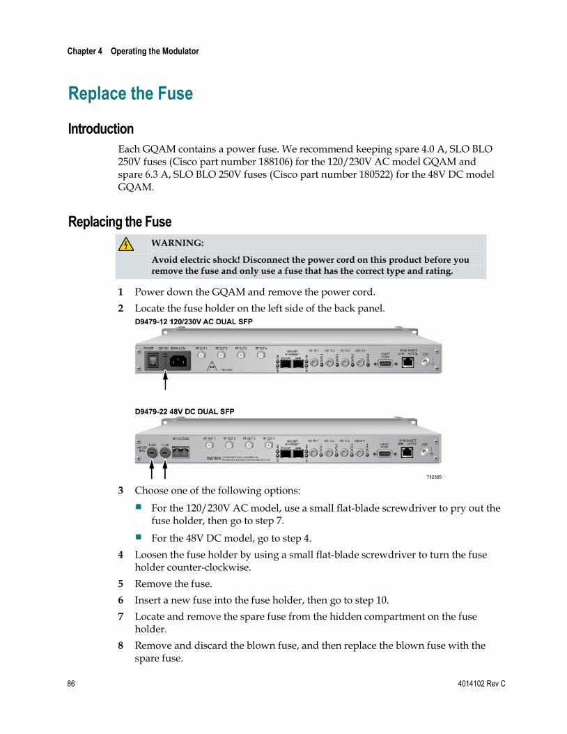
Chapter 4 Operating the Modulator
86 4014102 Rev C
Replace the Fuse
Introduction
Each GQAM contains a power fuse. We recommend keeping spare 4.0 A, SLO BLO 250V fuses (Cisco part number 188106) for the 120/230V AC model GQAM and spare 6.3 A, SLO BLO 250V fuses (Cisco part number 180522) for the 48V DC model GQAM.
Replacing the Fuse
WARNING:
Avoid electric shock! Disconnect the power cord on this product before you remove the fuse and only use a fuse that has the correct type and rating.
1 Power down the GQAM and remove the power cord.
2 Locate the fuse holder on the left side of the back panel.
3 Choose one of the following options:
For the 120/230V AC model, use a small flat-blade screwdriver to pry out the fuse holder, then go to step 7.
For the 48V DC model, go to step 4.
4 Loosen the fuse holder by using a small flat-blade screwdriver to turn the fuse holder counter-clockwise.
5 Remove the fuse.
6 Insert a new fuse into the fuse holder, then go to step 10.
7 Locate and remove the spare fuse from the hidden compartment on the fuse holder.
8 Remove and discard the blown fuse, and then replace the blown fuse with the spare fuse.

Replace the Fuse
4014102 Rev C 87
9 Place a new fuse in the hidden compartment where you removed the spare. This fuse will now be your spare fuse.
10 Insert the fuse holder into the back panel.
11 Choose one of the following options:
For the 120/230V AC model, snap the fuse holder in place.
For the 48V DC model, tighten the fuse holder by using a small flat-blade screwdriver to turn the fuse holder clockwise.
12 Replace the power cord and power on the GQAM.

Chapter 4 Operating the Modulator
88 4014102 Rev C
Diagnose the Fan
Introduction
If a fan fails or is failing, either the MAJOR LED or the MINOR LED on the front panel will light and you will see either a fan failure alarm message or an excessive temperature alarm message on the front panel LCD screen, or perhaps both.
WARNING:
Avoid electric shock and damage to this product! Replace the fan only with a genuine replacement fan from Cisco. Contact your Cisco Customer Service Representative to order replacement fans.
Diagnosing the Fan
The following illustrations are examples of the alarm displays you will see on the front panel LCD screen.
Fan Failure Alarm
Notes:
The fan failure alarm is a Major alarm.
The fan failure alarm can display for fan number 1 through fan number 6.
Excessive Temperature Alarm
Notes:
The excessive temperature alarm is a Minor alarm.
The excessive temperature alarm can display for RF module 1 through RF module 4.
Replacing the Fan
Go to Replace the Fan (on page 90) for detailed procedures on replacing a fan unit.

Diagnose the Fan
4014102 Rev C 89
Important! If a fan fails or is failing, contact your Cisco Customer Service Representative to obtain a replacement fan.
Notes:
The part number for the replacement fan unit is 4003088.
The part number for the kit that includes the replacement fan and instruction sheet is 4007620-40.

Chapter 4 Operating the Modulator
90 4014102 Rev C
Replace the Fan
Introduction
The GQAM modulator has three dual fan units on the side panel. Each of these units contains two fan rotors. You must replace the entire dual fan unit if one of the fan rotors should fail. The fan units are designed to be “hot swappable,” meaning that you do not necessarily have to power down the GQAM to replace a fan unit that has failed.
Important! In order to hot swap a dual fan unit, you must have the following:
Sufficient length in all cords and cables so you can slide the device forward in the rack far enough to fully access the dual fan units on the side panel.
The ability to externally support the GQAM with a cart or table or with the assistance of another person.
Note: If you do not have sufficient length in all cords and cables, you will have to power off the unit, disconnect all cords and cables, and completely remove the GQAM from the rack to replace a dual fan unit that has failed.
This section provides the procedure for replacing a dual fan unit on the GQAM by either hot swapping the fan unit, or by powering off, disconnecting, and removing the GQAM completely from the rack.
When Can I Perform This Procedure?
If you cannot hot swap the dual fan unit, you need to replace the fan unit during a maintenance window. This is necessary because you will have to power off and disconnect the GQAM to replace the fan unit, thereby temporarily disrupting all broadcast services configured and provisioned on this GQAM.
Important! Schedule the maintenance window to replace the fan as soon as possible to avoid damage to the GQAM.
Location of Fans
The fans are located on the GQAM side panel as follows:
Fans 1 and 2 are located nearest to the back panel.
Fans 3 and 4 are the middle fans.
Fans 5 and 6 are located nearest to the front panel.

Replace the Fan
4014102 Rev C 91
Replacing the Fan
WARNING:
Avoid damage to this product! Replace the dual fan unit only with a genuine replacement fan unit from Cisco. Contact your Cisco Customer Service Representative to order replacement fan units.
1 Are the cables connected to the back panel long enough to allow you to slide the GQAM forward into the rack to sufficiently access the side panel where the fan units are located?
If yes, carefully remove the screws that secure the GQAM in the rack, and carefully slide the GQAM forward in the rack until you can access the fan units. Then, go to step 5.
CAUTION:
You must be able to externally support the GQAM with a cart or table or with the assistance of another person when you slide the chassis forward in the rack.
If no, go to step 2.
2 If you cannot slide the GQAM forward in the rack because some or all of the cables in the rack are not long enough to access the fan, wait to replace the fan until you have a maintenance window. Then, choose one of the following options:
If some of the cables are not long enough, you must power off the GQAM and disconnect any cables that are not long enough.
If all of your cables are too short, you must power off the GQAM and disconnect all the cables, including the power cable.
3 Remove the screws that secure the GQAM in the rack. Then, remove the GQAM completely from the rack to replace the fan unit.
4 After removing the GQAM, place it carefully on a sturdy flat surface.
5 Carefully remove the screws that secure the 9-pin connector to the side panel and place them in a safe location nearby.
6 Carefully remove the screws and sleeves that secure the fan unit to the side panel and place them in a safe location nearby.

Chapter 4 Operating the Modulator
92 4014102 Rev C
Important: The sleeves are loose and are not connected to the fan. Be careful not to drop them.
7 Remove the non-functioning fan unit and carefully disconnect the 9-pin connector. Set this fan unit aside for safe disposal later.
8 Hold the new fan unit in place on the side panel of the GQAM so that the rotor with three fan blades is visible.
9 Place the sleeves in the proper location on the fan (as shown in the diagram), insert the screws through the sleeves, and then carefully tighten the screws that secure the fan to the side panel.
Important: Do not over tighten or cross thread the screws!
10 Carefully insert the 9-pin connector into the 9-pin socket, and then replace and carefully tighten the screws that secure the 9-pin connector to the side panel.
Important: Do not over tighten or cross thread the screws!
11 Did you have to remove the GQAM completely from the rack?
If yes, go to step 13.
If no, go to step 12.
12 Replace the GQAM into its original position in the rack and secure it in the rack using the original screws. Then, go to step 14.
13 Replace the GQAM into its original position in the rack, secure it in the rack using the original screws, reconnect all cables, reconnect the power cord, and then power on the GQAM.
14 Does the new fan unit operate properly?
If yes, you have completed this procedure.
If no, contact Cisco Services for assistance.
4014102 Rev C 93
Introduction
This chapter provides explanations of major, minor, and status alarm conditions and instructions for checking alarms. This chapter also includes an alarm troubleshooting table, arranged alphabetically according to the front panel LCD message, with additional information for resolving alarm conditions. In addition, this chapter provides examples of boot screen error messages that identify boot and software loading errors or failures.
5 Chapter 5 Troubleshooting the GQAM
In This Chapter
Alarm Conditions ................................................................................. 94
Troubleshooting Alarm Messages ...................................................... 96
Troubleshooting Boot Screen Error Messages ................................ 104

Chapter 5 Troubleshooting the GQAM
94 4014102 Rev C
Alarm Conditions
Introduction
This section describes major, minor, and status alarms and explains how to access and read the alarms displayed on the front panel LCD of the GQAM. Refer to Troubleshooting Alarm Messages (on page 96) for a list of alarm messages that appear on the LCD screen, their level of severity, and possible solutions.
Purpose and Severity Levels of GQAM Alarms
Alarms provide system operators with an indication of an abnormal condition. Alarm messages appear on the Alarm Status screen when hardware or software conditions occur that might cause the GQAM to operate incorrectly or fail. Examples of such conditions include temperature fluctuations, power supply failure, communication problems, or the detection of bad data. All alarms are automatically enabled after powering up the GQAM.
Alarm levels are classified as major, minor, and status alarms. Each level is described as follows:
Major Alarms – A major alarm indicates a fatal error, that is, a complete loss of functionality. Major alarms occur for hardware or software conditions that indicate a serious disruption of service or the malfunctioning or failure of important circuits. These situations require the immediate response of the technician to restore or maintain system operability. The front panel of the GQAM contains a MAJOR LED to alert the operator that a major alarm is pending.
Minor Alarms – A minor alarm indicates a non-fatal error condition. The GQAM may continue to operate with some loss of functionality. The front panel of the GQAM contains a MINOR LED to alert the operator that a minor alarm is pending.
Status Alarms – The status alarm indicates that some state in the GQAM has changed. Status alarms are provided to alert the DNCS operator that possible changes are occurring at the GQAM site by someone pressing the front panel keys or by someone using the craft port. These are generally one-time events, such as a front panel event change. In this case, the alarm is issued with the level “status” each time you press the ENTER key on the front panel of the GQAM. Status alarms might not affect GQAM functionality.

Alarm Conditions
4014102 Rev C 95
LCD Alarm Display
The front panel of the GQAM displays alarm messages in the following standard display.
The alarm message appears on the second line of the display. In this example, the message indicates a loss of signal to the ASI Input, which is a major alarm condition.
Reading the Display 1 Press OPTIONS. The Alarm Status Level screen appears.
Note: Each alarm description appears for approximately 1 second before displaying the next alarm. If no alarms are active, a NO Active Alarms message appears.
2 Press ENTER. The default screen appears.

Chapter 5 Troubleshooting the GQAM
96 4014102 Rev C
Troubleshooting Alarm Messages
Introduction
If the front panel LCD displays an alarm condition, fails a self-test, or does not work properly, refer to the table in this section to find and correct the cause. Some alarm conditions may require you to contact Cisco.
See Troubleshooting Boot Screen Error Messages (on page 104) for resolving problems encountered during the start-up process.
Front Panel LCD Alarm Messages
The following table lists Alarm Messages displayed on the front panel LCD, the default level of severity, a probable cause for the alarm, and suggestions for correcting the alarm condition.
Notes:
The LCD descriptions for each alarm are arranged in alphabetical order.
Alarm messages that occur for the 16 RF outputs or the four ASI input ports are listed only once. The numbers in parentheses indicate the range of port numbers that might be affected by the alarm.
Example: The “Input (1-5) errored MPEG packet” description corresponds to the Input port that is affected.
LCD Description
Alarm Level
Probable Cause Check and Correct
Craft event change
Status GQAM settings were viewed or changed from the craft port
Verify that all services are still functioning correctly
Fans failure (1-6)
Major Ventilation fan failure Contact Cisco Services
Front panel event change
Status GQAM settings were changed from the craft port
Verify that all services are still functioning correctly
Hardware error
Major General-purpose hardware error or failure
Contact Cisco Services
Input (1-5) errored MPEG packets
Minor Error occurred in the header of MPEG packets as they arrived at the indicated Input port
Contact Cisco Services

Troubleshooting Alarm Messages
4014102 Rev C 97
LCD Description
Alarm Level
Probable Cause Check and Correct
Input (1-5) FIFO overflow
See also Input (1-5) packets were dumped
Minor First-in first-out (FIFO) overflow occurred and packet data has been lost. This indicates one or more of the following conditions:
Too many sessions defined from the DNCS for the GQAM
The data rate as defined from the DNCS for the GQAM session is too low, which also means that the data rate of the ASI input to the GQAM is too high
Hardware problem
Incorrect modulation mode
Reduce the data rate of input to the GQAM by doing the following:
– Reducing amount of incoming data
– Reducing amount of data added to the stream
– Increasing the modulation mode
Verify and correct session rate targets and threshold values
Contact Cisco Services
Input (1-5) loss of input signal
Major No signal. This indicates one or more of the following conditions:
An upstream device that provides input to the GQAM has failed or is offline
A cable has been disconnected
Check for loose or broken DVB ASI or GbE cable connections
Check that DVB ASI and GbE outputs of upstream devices are active
Run the Doctor Report to troubleshoot network connectivity issues
Contact Cisco Services
Input (1-5) MPEG continuity error
Minor MPEG continuity error counter; one or more MPEG packets have been dropped
Check one or more upstream devices connected to the GbE ports or the DVB ASI input ports
Contact Cisco Services
Input (1-5) MPEG Transport Error
Minor MPEG transport error indicator counter; error occurred in the header of the MPEG packet
Check one or more upstream devices connected to the GbE ports or the DVB ASI input ports
Run the Doctor Report to troubleshoot network connectivity issues
Contact Cisco Services
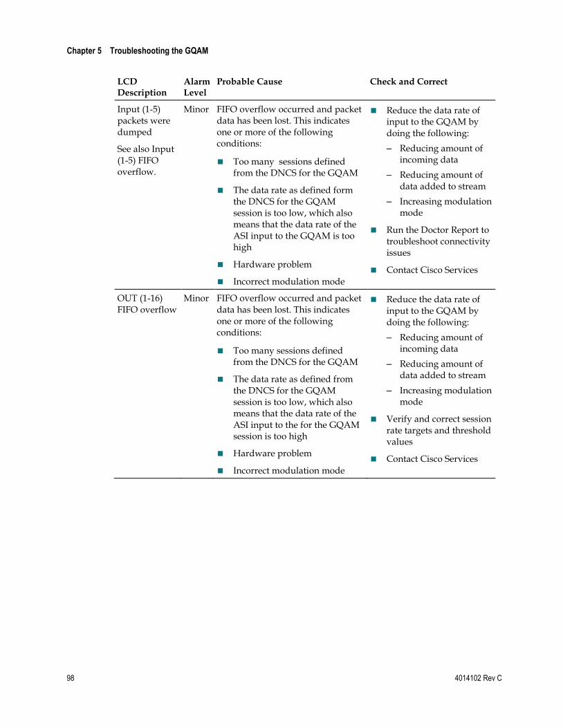
Chapter 5 Troubleshooting the GQAM
98 4014102 Rev C
LCD Description
Alarm Level
Probable Cause Check and Correct
Input (1-5) packets were dumped
See also Input (1-5) FIFO overflow.
Minor FIFO overflow occurred and packet data has been lost. This indicates one or more of the following conditions:
Too many sessions defined from the DNCS for the GQAM
The data rate as defined form the DNCS for the GQAM session is too low, which also means that the data rate of the ASI input to the GQAM is too high
Hardware problem
Incorrect modulation mode
Reduce the data rate of input to the GQAM by doing the following:
– Reducing amount of incoming data
– Reducing amount of data added to stream
– Increasing modulation mode
Run the Doctor Report to troubleshoot connectivity issues
Contact Cisco Services
OUT (1-16) FIFO overflow
Minor FIFO overflow occurred and packet data has been lost. This indicates one or more of the following conditions:
Too many sessions defined from the DNCS for the GQAM
The data rate as defined from the DNCS for the GQAM session is too low, which also means that the data rate of the ASI input to the for the GQAM session is too high
Hardware problem
Incorrect modulation mode
Reduce the data rate of input to the GQAM by doing the following:
– Reducing amount of incoming data
– Reducing amount of data added to stream
– Increasing modulation mode
Verify and correct session rate targets and threshold values
Contact Cisco Services
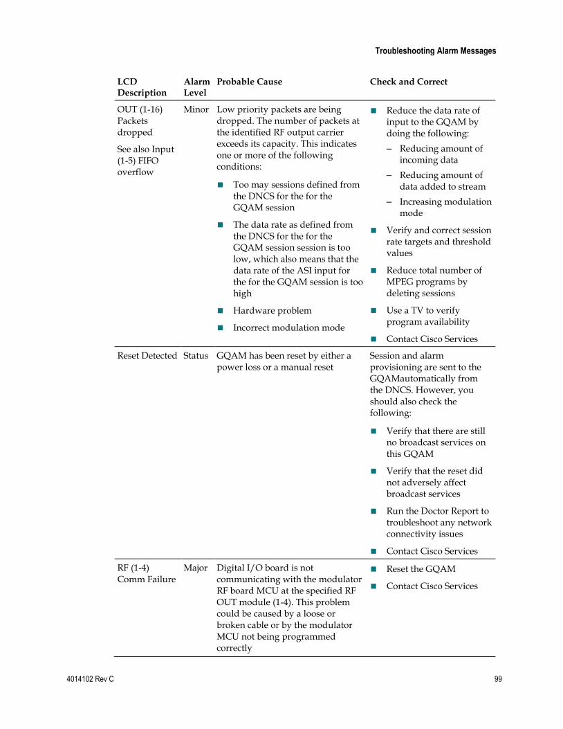
Troubleshooting Alarm Messages
4014102 Rev C 99
LCD Description
Alarm Level
Probable Cause Check and Correct
OUT (1-16) Packets dropped
See also Input (1-5) FIFO overflow
Minor Low priority packets are being dropped. The number of packets at the identified RF output carrier exceeds its capacity. This indicates one or more of the following conditions:
Too may sessions defined from the DNCS for the for the GQAM session
The data rate as defined from the DNCS for the for the GQAM session session is too low, which also means that the data rate of the ASI input for the for the GQAM session is too high
Hardware problem
Incorrect modulation mode
Reduce the data rate of input to the GQAM by doing the following:
– Reducing amount of incoming data
– Reducing amount of data added to stream
– Increasing modulation mode
Verify and correct session rate targets and threshold values
Reduce total number of MPEG programs by deleting sessions
Use a TV to verify program availability
Contact Cisco Services
Reset Detected Status GQAM has been reset by either a power loss or a manual reset
Session and alarm provisioning are sent to the GQAMautomatically from the DNCS. However, you should also check the following:
Verify that there are still no broadcast services on this GQAM
Verify that the reset did not adversely affect broadcast services
Run the Doctor Report to troubleshoot any network connectivity issues
Contact Cisco Services
RF (1-4) Comm Failure
Major Digital I/O board is not communicating with the modulator RF board MCU at the specified RF OUT module (1-4). This problem could be caused by a loose or broken cable or by the modulator MCU not being programmed correctly
Reset the GQAM
Contact Cisco Services

Chapter 5 Troubleshooting the GQAM
100 4014102 Rev C
LCD Description
Alarm Level
Probable Cause Check and Correct
RF (1-4) DC Lock detect error
See also RF (1-4) UC Lock detect error
Major Downconverter (DC) lock detect signal not functioning correctly. During Modulator MCU Power On Self Test (POST), the lock detect signal from the downconverter phase-locked loop (PLL) did not indicate an unlocked condition when one existed
Note: Since the MCU cannot correctly detect locked or unlocked status, the RF Output field displays “MUTED” when this condition occurred
The output converter synthesizer lock detect circuitry has malfunctioned
Contact Cisco Services
RF (1-4) DC PLL unlocked
Major Downconverter (DC) PLL synthesizer cannot lock. The output frequency may not be correct. The RF Output field displays “MUTED” when this condition exists
Contact Cisco Services
RF (1-4) EEPROM failure
Minor Modulator EEPROM failure. The EEPROM on the modulator board is not present or is not operational. If this alarm is set, RF calibration data is not available and the “RF (1-4) Level not calibrated” alarm is also active
Contact Cisco Services
RF (1-4) Exceeded max temp
Minor The internal temperature of the GQAM is more than 70ºC (158ºF)
Remove vent obstructions
Provide more cooling and ventilation
Check the exhaust fans
Contact Cisco Services
Important! You should check the temperature on the GQAM daily or more frequently if possible.
RF (1-4) level not calibrated
Minor One of the RF Level settings is not calibrated to the correct frequency or the EEPROM that stores the calibration data is not operational
Contact Cisco Services

Troubleshooting Alarm Messages
4014102 Rev C 101
LCD Description
Alarm Level
Probable Cause Check and Correct
RF (1-4) Power Supply failure
Minor At least one internal power regulator failed. The RF Output field displays "MUTED" when this condition exists
Contact Cisco Services
RF (1-4) UC Lock detect error
Major Upconverter (UC) PLL lock detect signal is functioning incorrectly. The RF Output field idsplays "MUTED" when this condition exists
Contact Cisco Services
RF (1-4) UC PLL unlocked
Major Modulator UC PLL is unlocked. The output frequency may not be correct. The RF Output field displays "MUTED" when this condition exists
Contact Cisco Services
Runtime error
(Operating System)
Major General purpose software error Reset the GQAM by the power switch or, if possible, by DNCS Control
Contact Cisco Services
"Session xxx ca error" where xxx is a number from 0-991
Minor An error in the conditional access (CA) encryption for a session has been detected. This could mean that an unencrypted signal is being transmitted
Delete the failed session and then restart the session
Check and correct the package setup and encryption settings on the DNCS
Check the VOD sessions for bad interactive session key (ISK) messages
Check all hardware settings
Contact Cisco Services

Chapter 5 Troubleshooting the GQAM
102 4014102 Rev C
LCD Description
Alarm Level
Probable Cause Check and Correct
"Session xxx data error" where xxx is a number from 0-991
Minor
Minor
The data flow for the session is lesser or greater than what has been defined by the DNCS for the session indicating one of the following underflow or overflow conditions:
Cause Code 1 - Underflow – This session data rate for the session drops to 0 (zero) or is less than expected
Important! The session rate dropping to 0 (zero) triggers an underflow alarm, but is not the result of a loss of signal condition. When a loss of signal occurs, the underflow alarm is not reported. This prevents the system from being overwhelmed with a large number of session data alarms. Alarms that occur as a result of higher level alarms are not reported.
Cause Code 2-Overflow – The data rate for this session exceeds the provisioned data rate
Verify and correct any session setup problems including the session rate target value. If session data is correct, data may be corrupted because of hardware problems.
Note: Select data rates that you believe the program should not exceed.
For the overflow condition, teardown, rebuild, and then restart the session using a higher bandwidth
Run the Doctor Report on the DNCS and examine the report for any network connectivity issues or indications of loss of services
Contact Cisco Services
Cause Code 3 - PID enable error –- A PID that should be enabled is not enabled on the GQAM
If this alarm occurs with this Cause Code and then quickly clears, it is not a cause for concern
Check the content of the input stream using an MPEG analyzer
Cause Code 6 - Continuity error – This alarm identifies the specific session on which the Input Port (1-5) continuity error alarm occurred
Contact Cisco Services
Cause Code 7 - PLL unlocked – The phase lock loop is unlocked for the given session
Contact Cisco Services

Troubleshooting Alarm Messages
4014102 Rev C 103
LCD Description
Alarm Level
Probable Cause Check and Correct
Cause Code 8 - Excess glue frame events – Glue frames prevent macroblocking. Excess glue frame events indicate that the associated output port is receiving too much data. When the MPEG engine in the GQAM nears full output capacity, it begins to selectively choose video PIDs on which it will issue a "freeze frame" code in the MPEG video stream for that program and will drop the video packets for that session momentarily. This will happen only for sessions in which blue framing was enabled when the sessions was created. If this alarm occurs frequently, it is a signal that the output QAM carrying that session contains to much data
Reallocate the session from the QAM that appears to contain too much data to another QAM on the same GQAM modulator or to another GQAM modulator
"Session xxx program error" where xxx is a number from 0 to 991
Minor
Cause Code 1 – A cyclic redundancy check (CRC) error was detected on a PMT
Delete the session
Cause Code 2 – A new program map table (PMT) was detected
This is for information only. No action is required
Cause Code 3 – An attempt to create a session failed
Teardown and rebuild the session
Program Specific Information (PSI) Table data for the session contains errors
Check the upstream MPEG input sources connected to the GQAM
Contact Cisco Services

Chapter 5 Troubleshooting the GQAM
104 4014102 Rev C
Troubleshooting Boot Screen Error Messages
Introduction
This section contains examples of warning screens associated with booting error conditions. Some booting error conditions may require you to contact Cisco.
Booting Error Messages
The following table lists booting error conditions sorted alphabetically by error type, and provides suggestions for correcting the error condition.
Error Condition LCD Messages Check and Correct
Application Code Download Failure Screens
Bad TFTP Checksum
The following message appears if the GQAM is unable to download application code execution files from the TFTP server due to a bad checksum.
Bad TFTP App Checksum
Restarting...
The GQAM automatically reboots.
Unable to TFTP App Code (Boot Mode=2)
The following message appears if the GQAM is unable to download application code execution files from the TFTP server during boot mode 2.
Unable to TFTP App Code
Restarting...
The GQAM automatically reboots.
Unable to TFTP App Code (Boot Mode=1)
The following message appears if the GQAM is unable to download the application code execution files from the TFTP server during boot mode 1.
Unable to TFTP App Code
Continuing Startup...
The GQAM then starts the application program.
A corrupted application file may cause this condition.
Reinstall the GQAM package on the DNCS if all GQAMs have this error condition.
Check IP connectivity.
Contact Cisco Services.
Note: Refer to Understand the Boot Process (on page 62) for detailed descriptions of the boot process.

Troubleshooting Boot Screen Error Messages
4014102 Rev C 105
Error Condition LCD Messages Check and Correct
Boot Download Failure Screens
Unable to TFTP Boot Code (Boot Mode=1)
The following message appears if the GQAM is unable to download the boot code execution file from the TFTP server during boot mode 1.
Unable to TFTP Boot Code
Continuing Startup...
The GQAM then starts the application program.
Unable to TFTP Boot Code (Boot Mode=2)
The following message appears if the GQAM is unable to download the boot code execution file from the TFTP server during boot mode 2.
Unable to TFTP Boot Code
Restarting...
The GQAM then automatically reboots.
An incorrect DNCS configuration may also cause this condition.
Reinstall the GQAM package on the DNCS if all GQAMs have this error condition.
Check IP connectivity.
Contact Cisco Services.
Default Status Screen
If an RF carrier channel cannot be accessed or is missing, the following message appears:
CH1
Info Not Available
A possible RF hardware problem occurred.
Contact Cisco Services.
Incorrect Configuration File Screens
Invalid Config File (Boot Mode 1)
The following message appears when in boot mode 1 and the configuration file type is incorrect for the GQAM. The first line of the configuration file contains GqamBootpFileType=1.0.
Invalid File format
Continuing Startup...
The GQAM then starts the application program.
Invalid Config File (Boot Mode 2)
The following message appears when in boot mode 2 and the configuration file type is incorrect for the GQAM. The first line of the configuration file contains GqamBootpFileType=2.0.
Invalid File format
Restarting...
The GQAM then automatically reboots.
Correct the configuration file.
Contact Cisco Services.
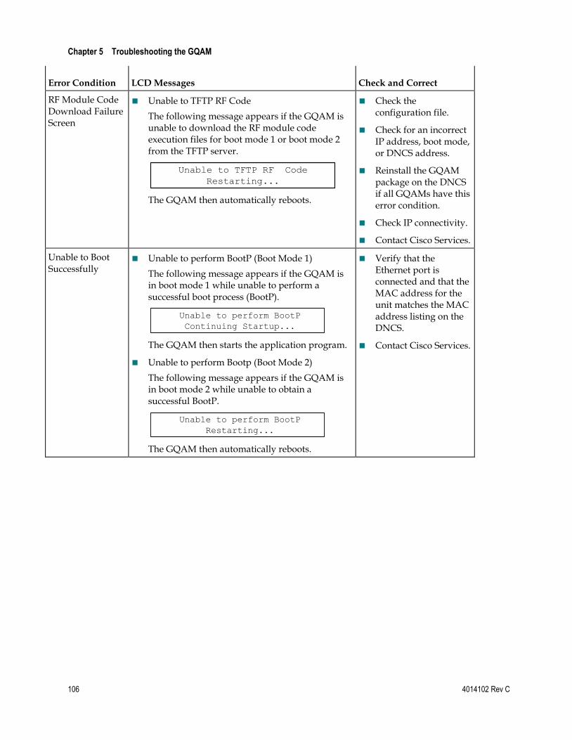
Chapter 5 Troubleshooting the GQAM
106 4014102 Rev C
Error Condition LCD Messages Check and Correct
RF Module Code Download Failure Screen
Unable to TFTP RF Code
The following message appears if the GQAM is unable to download the RF module code execution files for boot mode 1 or boot mode 2 from the TFTP server.
Unable to TFTP RF Code
Restarting...
The GQAM then automatically reboots.
Check the configuration file.
Check for an incorrect IP address, boot mode, or DNCS address.
Reinstall the GQAM package on the DNCS if all GQAMs have this error condition.
Check IP connectivity.
Contact Cisco Services.
Unable to Boot Successfully
Unable to perform BootP (Boot Mode 1)
The following message appears if the GQAM is in boot mode 1 while unable to perform a successful boot process (BootP).
Unable to perform BootP
Continuing Startup...
The GQAM then starts the application program.
Unable to perform Bootp (Boot Mode 2)
The following message appears if the GQAM is in boot mode 2 while unable to obtain a successful BootP.
Unable to perform BootP
Restarting...
The GQAM then automatically reboots.
Verify that the Ethernet port is connected and that the MAC address for the unit matches the MAC address listing on the DNCS.
Contact Cisco Services.

Troubleshooting Boot Screen Error Messages
4014102 Rev C 107
Error Condition LCD Messages Check and Correct
Unable to Download Configuration File from TFTP Server
Unable to TFTP Config File (Boot Mode 1)
The following message appears when in boot mode 1 and the GQAM is unable to download the configuration file from the TFTP server.
Problem with Config File
Continuing Startup...
The GQAM then starts the application program.
Unable to TFTP Config File (Boot Mode 2)
The following message appears when in boot mode 2 and the GQAM is unable to download the configuration file from the TFTP server.
Problem with Config File
Restarting...
The GQAM then automatically reboots.
Verify that the configuration file provisioned on the DNCS is present in the DNCS File system.
An incorrect DNCS configuration may cause this error condition.
Contact Cisco Services.


4014102 Rev C 109
If You Have Questions
If you have technical questions, call Cisco Services for assistance. Follow the menu options to speak with a service engineer.
Access your company's extranet site to view or order additional technical publications. For accessing instructions, contact the representative who handles your account. Check your extranet site often as the information is updated frequently.
6 Chapter 6 Customer Information


4014102 Rev C 111
A Appx auto letter Appendix A Technical Specifications
Introduction
This appendix lists the power, rack, and environmental requirements for installing the GQAM and provides technical specifications.
In This Appendix
Installation and Operation Requirements ....................................... 112
RF Specifications ................................................................................. 114
ASI Input Specifications ..................................................................... 115
Modulation Specifications ................................................................. 116
Digital I/O Performance Specifications ........................................... 117
Connector Type ................................................................................... 118
Factory Default Settings ..................................................................... 119
Standard Output Frequencies ........................................................... 120

Appendix A Technical Specifications
112 4014102 Rev C
Installation and Operation Requirements
Introduction
This section contains tables that define specifications specific to installing and operating the GQAM.
Power Requirements Table
Item Specification
Supply Voltage 90 V AC to 130 V AC @ 47 Hz to 63 Hz (AC unit)
180 V AC to 264 V AC @ 47 Hz to 63 Hz (AC unit)
-42 V to -57 V DC (DC unit)
Fuses 4.0 A SLO BLO 250 V (AC unit)
6.3 A SLO BLO 250 V (DC unit)
Line Frequency 47 Hz to 63 Hz (AC unit only)
Power Required 155 VA (typical)
Power Dissipated 151 Watts (typical)
In Rush Current 35 amps maximum, Vin = 130 VAC (AC unit)
75 amps maximum, Vin = 264 VAC (AC unit)
15 amps maximum, Vin = -57 VDC (DC unit)
Rack Requirements Table
Item Specification
Rack Mount Type EIA RS-310
Height 1.75 in./44.45 mm
Width 19 in./482.6 mm
Depth 22.5 in./571.5 mm
Weight 13.5 lb./5.4 kg

Installation and Operation Requirements
4014102 Rev C 113
Environmental Requirements Table
Item Specification
Operating Temperature 0°C (32°F) to 50°C (122°F)
CAUTION:
Avoid damage to this product! Your warranty is void if you operate this product above the maximum specified operating temperature.
Use caution when installing wiring and racks to avoid obstruction of air flow into the side air vents of the GQAM, or out of the vent fans at the GQAM side panel.
Important: You must use the supplied notched rack mounts (Cisco part numbers 734845 and 734846) to mount the GQAM in the rack. These rack mounts allow correct air circulation through the unit.
Storage Temperature Range -10°C (14°F) to 70°C (158°F)
Operating Humidity 5% to 95%, non-condensing
Vibration Susceptibility No data errors with a chassis vibration of 0.5 Gs. No data errors with a vibration frequency of 10 Hz to 400 Hz
Electrostatic Shock Susceptibility No damage sustained from five discharges of 15 KV IEC electrostatic discharge model (150pF + 150 Ω) to all exposed connections

Appendix A Technical Specifications
114 4014102 Rev C
RF Specifications
Specification Range
Frequency Range (center frequency) 91 MHz to 869 MHz
Minimum Tuning Step Size 250 kHz
RF Output Power Level +42 dBmV to +54 dBmV minimum range
RF Output Impedance 75 Ω
RF Output Return Loss (carrier on) > 12 dB (within output channel)
Spurious Outputs (50 MHz to 1.1 GHz) single frequency modulated output related
< -60 dB (relative to the average power of the QAM channel with the highest power level)
Noise Floor (out of band) < -136 dBc/Hz > 40 MHz from center frequency
Phase Noise -84 dBc/Hz 10 kHz from carrier -86 dBc/Hz 10 kHz from carrier (typical)
Output Power Level Change Over Tuning Range
2.0 dB
Output Frequency Error (over temperature) < 3 ppm

ASI Input Specifications
4014102 Rev C 115
ASI Input Specifications
Specification Value
Minimum Sensitivity 200 mV (p-p)
Maximum Input Voltage 880 mV (p-p)
Input Impedance 75 Ω
Input Return Loss > 17 dB (27 MHz to 270 MHz)

Appendix A Technical Specifications
116 4014102 Rev C
Modulation Specifications
6 MHz Spec
Type Alpha Interleaver Symbol Rate (Msymbols/sec)
Data Rate (megabits/sec)
Bandwidth
ITU-A DAVIC/ DVB 64
12% I=12, J=17 5.304 29.328 6 MHz
ITU-A DAVIC 256 12% I=204, J=1 5.304 39.104 6 MHz
ITU-B QAM 64 18% I=128, J=1 5.056941 26.971 Mb/s 6 MHz
ITU-B QAM 256 12% I=128, J=1 5.360537 38.811 Mb/s 6 MHz
ITU-C DAVIC/ DVB 64
13% I=12, J=17 5.274 29.162 Mb/s 6 MHz

Digital I/O Performance Specifications
4014102 Rev C 117
Digital I/O Performance Specifications The following table provides digital input and output performance specifications.
Specification Value
Maximum Input Rate 1.804 Gbps - 213 Mbps for each of the four ASI input ports, plus 952 Mbps (GbE payload rate)
Gigabit Ethernet Input Rate 952 Mbps (max)
Maximum Aggregate Output Rate (including data insertion)
620 Mbps
Maximum Total Sessions 992
Maximum Number of Sessions per Output 61 sessions per channel
Maximum Number of PIDs per Session 16
Maximum Number of PIDs per Input Transport
8192, per MPEG spec
Maximum Number of PIDs for all Input Transports
32K
Maximum Packet Insertion Rate (for externally sourced packets)
500 Kbps maximum; 1 Kbps minimum
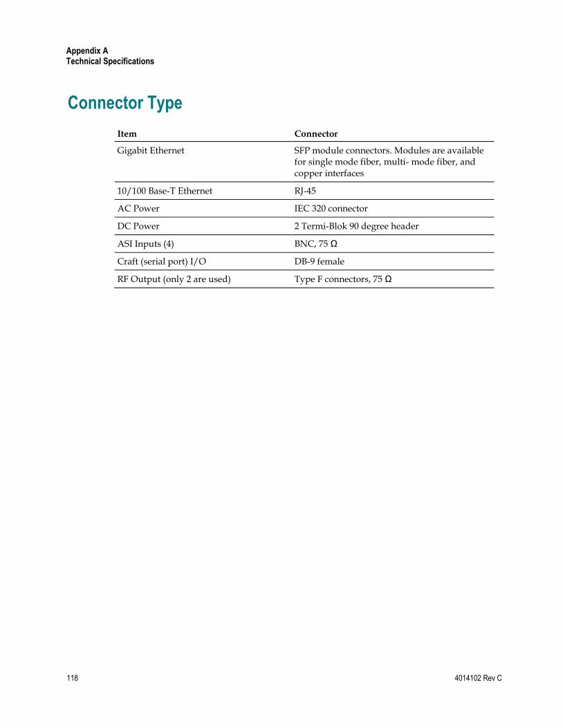
Appendix A Technical Specifications
118 4014102 Rev C
Connector Type
Item Connector
Gigabit Ethernet SFP module connectors. Modules are available for single mode fiber, multi- mode fiber, and copper interfaces
10/100 Base-T Ethernet RJ-45
AC Power IEC 320 connector
DC Power 2 Termi-Blok 90 degree header
ASI Inputs (4) BNC, 75 Ω
Craft (serial port) I/O DB-9 female
RF Output (only 2 are used) Type F connectors, 75 Ω

Factory Default Settings
4014102 Rev C 119
Factory Default Settings
Value Factory Setting
Boot Mode 2
Carrier Mode Modulated
Encryption PowerKEY
ITUB Interleave 128, 1
LCD Contrast 80%
Modulation Type ITUB 256
RF Frequency Highest Center Frequency Setting (867 MHz)
RF Mute Off (the output is not muted)
RF Output Level Midrange setting (50 dBmV)
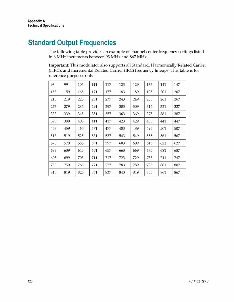
Appendix A Technical Specifications
120 4014102 Rev C
Standard Output Frequencies The following table provides an example of channel center frequency settings listed in 6 MHz increments between 93 MHz and 867 MHz.
Important: This modulator also supports all Standard, Harmonically Related Carrier (HRC), and Incremental Related Carrier (IRC) frequency lineups. This table is for reference purposes only.
93 99 105 111 117 123 129 135 141 147
153 159 165 171 177 183 189 195 201 207
213 219 225 231 237 243 249 255 261 267
273 279 285 291 297 303 309 315 321 327
333 339 345 351 357 363 369 375 381 387
393 399 405 411 417 423 429 435 441 447
453 459 465 471 477 483 489 495 501 507
513 519 525 531 537 543 549 555 561 567
573 579 585 591 597 603 609 615 621 627
633 639 645 651 657 663 669 675 681 687
693 699 705 711 717 723 729 735 741 747
753 759 765 771 777 783 789 795 801 807
813 819 825 831 837 843 849 855 861 867

4014102 Rev C 121
A
Add a Service Group • 55
Adjust the Frequencies of a Selected RF Channel
or CH Carrier • 34, 70
Adjust the RF Output Level of a Selected Carrier
• 15, 34, 35, 70
C
Change the Boot Mode • 62
Change the Carrier Mode of a Selected CH
Carrier • 70
Code Download Screens • 62
Connect Power Sources • 15, 25, 66
Connect the 10/100BaseT Ethernet Port • 15, 29
Connect the DVB ASI Input Ports • 15, 27
Connect the Gigabit Ethernet Ports • 31
Connect the RF OUT Ports • 32, 33
Connecting the Gigabit Ethernet Port Using
Fiber Optic Cables • 15
Connecting the Gigabit Ethernet Ports Using
CAT-5 Ethernet Cables • 15
Connecting the RF OUT Ports • 15
F
Front Panel Overview • 68, 70
I
Initial Boot Screens • 62
Install the Modulator Into a Rack • 14
Installation and Operation Requirements • 14
Installation Requirements • 14
M
Monitor Setup Options • 70
Mute the RF Output of a Selected CH Carrier •
35, 70
P
Provision GQAMs on the DNCS • 15, 34, 35
R
Record the MAC Address • 14, 17
Replace the Fan • 88
Resetting the Modulator • 66
S
Stacking Guidelines • 14, 18, 23
T
Troubleshooting Alarm Messages • 15, 94
Troubleshooting Boot Screen Error Messages •
15, 62, 96
Troubleshooting the GQAM • 77, 85
U
Understand the Boot Process • 15, 104
Understanding the File Selection Dialog Screen •
44
Unpack and Inspect the GQAM • 14, 18
V
Viewing the Program Count • 16
Viewing the Session Count • 16
Index

Cisco Systems, Inc. 5030 Sugarloaf Parkway, Box 465447 Lawrenceville, GA 30042
678 277-1120 800 722-2009
www.cisco.com
This document includes various trademarks of Cisco Systems, Inc. Please see the Notices section of this document for a list of the Cisco Systems, Inc. trademarks used in this document. Product and service availability are subject to change without notice.
© 2007, 2012 Cisco and/or its affiliates. All rights reserved. April 2012 Printed in USA
Part Number 4014102 Rev C


![Reversing and Malware Analysis Training Articles [2012] . cracking/Reversing... · Reversing and Malware Analysis Training Articles ... Step 1: Start with what you ... Reversing and](https://static.fdocuments.in/doc/165x107/5ab905fd7f8b9ac10d8db0ab/reversing-and-malware-analysis-training-articles-2012-crackingreversingreversing.jpg)