Installation and Operating Manual DAB Deep Well...
11
INSTALLATION AND OPERATING MANUAL FOR DAB DEEP WELL JET PUMPS
Transcript of Installation and Operating Manual DAB Deep Well...

INSTALLATION AND OPERATING MANUAL FOR DAB DEEP WELL JET PUMPS

Installation and Operating Manual DAB Deep Well Pumps.doc 28/07/2004 Page 2
GENERAL DATA Applications Self-priming centrifugal pump for suction up to 27 metres, reached by means of an ejector to be inserted in wells with a diameter of 4" or over. For use in supplying water to farmhouses and in small-scale agriculture. Constructional features of the pump Pump: Cast iron pump body and motor support. Technopolymer impeller and diffuser. Stainless steel pressure disc. Carbon/ceramic mechanical seal. Ejector: Cast iron body. Technopolymer A Venturi tube and brass nozzle. The ejector is available in three models (E20 - E25 - E30) to be chosen according to performance requirements. Constructional features of the motor Induction motor, closed and cooled with external ventilation. Rotor mounted on oversized greased sealed-for-life ball bearings. Built-in thermal and current overload protection and a capacitor permanently in circuit in the single-phase version. Three-phase motors should be protected with a suitable overload protection complying with the regulations in force. Manufactured according to CEI 61-69 standards (EN 60335-2-41). Motor protection: IP44 Terminal box protection: IP55 Insulation class: F Standard voltage: single-phase 220-240 V/50 Hz three-phase 230-400 V/50 Hz
TECHNICAL DATA - Operating range: up to 4.3 m3/h. - Liquid quality requirements: clean, free from solids or abrasive substances, non viscous,
non aggressive, non crystallized, chemically neutral, close to the characteristics of water.
- Liquid temperature range: from 0°C to +35°C for domestic use (EN 60335-2-41) from 0°C to +40°C for other uses
- Maximum ambient temperature: +40°C - Maximum operating pressure: DP 81 - DP 100 6 bar (600 kPa)
DP 151 - DP 251 8 bar (800 kPa) - Installation: fixed in a horizontal position - Special executions on request: other voltages and/or frequencies
N PARTS MATERIALS 1 PUMP BODY CAST IRON 200 UNI ISO 185 2 EJECTOR BODY CAST IRON 200 UNI ISO 185 3 SUPPORT CAST IRON 200 UNI ISO 185 4 IMPELLER TECHNOPOLYMER 6 DIFFUSER TECHNOPOLYMER 7 SHAFT WITH ROTOR STAINLESS STEEL AISI 416
X12 CrS13 UNI 6900/71 (DP 80 – DP 100) STAINLESS STEEL AISI 303
X10CrNiS 1809 UNI 6900/71 (DP 151 – DP 251) 8 VENTURI TECHNOPOLYMER 9 JET BRASS 16 MECHANICAL SEAL CARBON/CERAMIC/NBR 28 BODY O RING NBR RUBBER

Installation and Operating Manual DAB Deep Well Pumps.doc 28/07/2004 Page 3
DEEP WELL AND SHALLOW WELL CONVERTABLE 151 - 251
DP 81 – DP 100
Warning: Pumps must not operate below their minimum “Delivery Pressure” as shown in the accompanying charts, as pumps will cavitate (loss of prime, air in water, fluctuating pressure gauge and extra pump noise are indications of cavitation), causing damage to pump components including bearings. E.g.1. DP81 pump with E25 Ejector Type at Suction Depth of 9 m must not operate with a delivery pressure below 1.5 bar.E.g.2. DP100 pump with E30 Ejector Type at Suction Depth of 21 m must not operate with a delivery pressure below 2.0 bar. If cavitation persists, delivery pressure may need to be raised, as suction depth may be lower than expected.

Installation and Operating Manual DAB Deep Well Pumps.doc 28/07/2004 Page 4
DP 151 – 251
Warning: Pumps must not operate below their minimum “Delivery Pressure” as shown in the accompanying charts, as pumps will cavitate (loss of prime, air in water, fluctuating pressure gauge and extra pump noise are indications of cavitation), causing damage to pump components including bearings. E.g.1. DP151 pump with E20 Ejector Type at Suction Depth of 9 m must not operate with a delivery pressure below 3.0 bar.E.g.2. DP251 pump with E30 Ejector Type at Suction Depth of 21 m must not operate with a delivery pressure below 4.0 bar. If cavitation persists, delivery pressure may need to be raised, as suction depth may be lower than expected.

Installation and Operating Manual DAB Deep Well Pumps.doc 28/07/2004 Page 5
PRELIMINARY CONSIDERATIONS Location Pump can be located at the bore or well, or can be offset some distance away from the water source. For best performance, the pump should be located as close as possible to the water source. Ventilation, cover and drainage must be provided to prevent damage from moisture to the motor and switches if fitted. The pump must be firmly anchored and pipe work supported. The pump and all piping must be protected from freezing, and pump and piping drained when not in use if there is a danger of freezing. Bore Conditions New bores should be pumped clean of all sand and foreign matter before installing the pump to prevent damage to the pumping system. The non-return valve should be installed a minimum of 2 metres from the bottom of the bore to prevent sand, mud and other foreign matter from entering the pumping system. The well must be capable of supplying a sufficient quantity of water to satisfy the demands of the pump. The water level must draw down below the maximum rated depth of the pump, or loss of capacity and prime as well as damage to the pump will occur. Piping Old or badly scaled pipe should not be used as dislodged flakes of scale can disrupt the operation of the injector assembly and cause pumping malfunction. Use only pipe in good condition, free of rust or scale. Threads should be sharp and clean and tightened to manufacturers’ specifications. All threaded joints should be sealed appropriately either by Teflon tape or approved sealant. Note: The entire system must be air and water tight for efficient operation. Type of Pipe Plastic or galvanised steel pipe may be used in the installation of jet pumps. Plastic piping must have a minimum pressure rating of 12 bar (174 psi). Water to Pump Piping All offset piping should slope upwards from water source to pump. Avoid dips or pockets in offset piping, or air will accumulate at high points and make priming difficult. Install unions at pump and at bore head to aid in servicing. Allow enough room around pump and piping installation to allow the use of wrenches, installation and servicing.
Installation and Operating Manual DAB Deep Well Pumps.doc 28/07/2004 Page 6
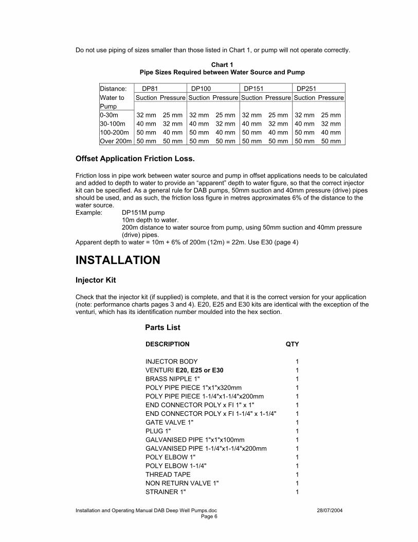
Do not use piping of sizes smaller than those listed in Chart 1, or pump will not operate correctly.
Chart 1 Pipe Sizes Required between Water Source and Pump
Distance: DP81 DP100 DP151 DP251 Water to Suction Pressure Suction Pressure Suction Pressure Suction PressurePump 0-30m 32 mm 25 mm 32 mm 25 mm 32 mm 25 mm 32 mm 25 mm 30-100m 40 mm 32 mm 40 mm 32 mm 40 mm 32 mm 40 mm 32 mm 100-200m 50 mm 40 mm 50 mm 40 mm 50 mm 40 mm 50 mm 40 mm Over 200m 50 mm 50 mm 50 mm 50 mm 50 mm 50 mm 50 mm 50 mm
Offset Application Friction Loss. Friction loss in pipe work between water source and pump in offset applications needs to be calculated and added to depth to water to provide an “apparent” depth to water figure, so that the correct injector kit can be specified. As a general rule for DAB pumps, 50mm suction and 40mm pressure (drive) pipes should be used, and as such, the friction loss figure in metres approximates 6% of the distance to the water source. Example: DP151M pump 10m depth to water.
200m distance to water source from pump, using 50mm suction and 40mm pressure (drive) pipes.
Apparent depth to water = 10m + 6% of 200m (12m) = 22m. Use E30 (page 4)
INSTALLATION Injector Kit Check that the injector kit (if supplied) is complete, and that it is the correct version for your application (note: performance charts pages 3 and 4). E20, E25 and E30 kits are identical with the exception of the venturi, which has its identification number moulded into the hex section. Parts List
DESCRIPTION QTY INJECTOR BODY 1 VENTURI E20, E25 or E30 1 BRASS NIPPLE 1" 1 POLY PIPE PIECE 1"x1"x320mm 1 POLY PIPE PIECE 1-1/4"x1-1/4"x200mm 1 END CONNECTOR POLY x FI 1" x 1" 1 END CONNECTOR POLY x FI 1-1/4" x 1-1/4" 1 GATE VALVE 1" 1 PLUG 1" 1 GALVANISED PIPE 1"x1"x100mm 1 GALVANISED PIPE 1-1/4"x1-1/4"x200mm 1 POLY ELBOW 1" 1 POLY ELBOW 1-1/4" 1 THREAD TAPE 1 NON RETURN VALVE 1" 1 STRAINER 1" 1

Installation and Operating Manual DAB Deep Well Pumps.doc 28/07/2004 Page 7
Note: Illustrated parts list at end of this manual. Injector Kit Assembly All threaded joints should be sealed appropriately either by Teflon tape or approved sealant. Note: The entire system must be air and water tight for efficient operation. Screw venturi into injector body. Assemble poly pipe pieces and poly end connectors onto injector body, Assemble galvanised pipe pieces and poly elbows. Assemble galvanised pipe pieces with poly elbows onto pump. Assemble nipple and gate valve onto pump discharge.

Installation and Operating Manual DAB Deep Well Pumps.doc 28/07/2004 Page 8
Water to Pump Piping For pipe size recommendations refer to Chart 1 on page 6. Always seal pipe ends during installation to stop debris entering the drive and suction pipes, as blockages in the injector body and jet will seriously affect performance. Add sufficient pressure (drive) pipe and suction pipe to submerge the injector 3 to 5 metres below the pumping water level, making certain that the non-return valve plus strainer (foot valve) are at least 2 metres from the bottom of the bore. Check pipes and foot valve for leaks by filling pipes with water. A continuous loss of water indicates a leak in the piping, foot valve or unions and must be corrected. If no leaks are found, connect pressure and suction pipes from bore to pump. Unions in suction and pressure piping near pump and bore will aid in servicing. Leave enough surrounding room so that wrenches can be used easily. If larger than standard diameter pipe is to be connected to the injector assembly, the use of 2 m to 3m 25 mm and 32 mm risers is suggested so that there is sufficient length to accommodate the pipe deflection (without damage) required to fit the larger poly end connector/adaptors. General Fluids
The pump has been designed and built for pumping water, free from explosive substances and solid particles and fibres, with a density of 1000 kg/m3 and a kinematic viscosity of 1 mm2/s, and chemically non-aggressive liquids and having temperature range within 0 - + 400C. Electrical Connection
Caution! Always follow the safety regulations. Scrupulously follow the wiring diagrams inside the terminal board box. A skilled and licensed electrician must carry out the electrical installation. Ensure that the voltage is the same as the value shown on the motor plate and there is the possibility of making a good earth connection. In fixed installations, international Safety standards require the use of isolating switches with a fuse carrier base. Single-phase motors are provided with built-in thermal overload protection and may be connected directly to the mains. Three phase motors must be protected with an automatic switch (e.g. circuit breaker) calibrated to the value shown on the data plate of the motor. Line fuses: Model 240V 1ph 415V 3ph Fuse size (Amps) DP81 4 2 Fuse size (Amps) DP100 6 4 Fuse size (Amps) DP151 10 4 Fuse size (Amps) DP251 16 6

Installation and Operating Manual DAB Deep Well Pumps.doc 28/07/2004 Page 9
START UP Check motor shaft rotation. Before power is connected and pump started, it must be checked that the rotating parts turn freely. For this purpose remove the fan cover from its seat in the motor end cover. Insert a screwdriver in the notch on the motor shaft from the ventilation side. If there is a blockage, turn the screwdriver, tapping it gently with a hammer. Replace the fan cover, and check free rotation again to ensure that the fan cover does not come in contact with the fan. Before starting up, check that the pump is properly primed. Fill the pump and the pipes leading to the water source fully with clean water by means of the hole provided after removal of the filling plug on the pump body. This ensures that the mechanical seal is well lubricated and that the pump immediately starts to work. Dry operation causes irreparable damage to the mechanical seal. The filling plug must then be screwed back on carefully. On deep well installations, all air must be vented from the pressure (drive) and suction pipes as well as the pump body before the pump will prime. It may be necessary to fill the pump body several times to achieve prime.
DEEP WELL START UP Ensure pump and pipe work are completely primed. In some offset applications, forced priming may be necessary from the water source using an engine powered pump. Install a pipe tee in the drive or pressure pipe with a gate valve as close to the water source as possible. Whilst priming, start the engine driven pump and deep well pump together and run until all air is expelled. Reduce speed on the engine driven pump gradually whilst maintaining minimum drive pressure at the deep well pump by adjusting the gate valve. Close the suction gate valve once the pump maintains pressure. Seal off inline tee, as it may be needed in the future. The injector kit (if supplied) is provided with a control (gate) valve. Its purpose is to provide the back-pressure on the pump required to divert some of the pumped flow down the drive (pressure) pipe to give energy to the injector assembly to raise water up the suction pipe from depths. See Pages 3 and 4 for minimum delivery pressures. Ensure that the control valve (gate valve) is fitted to the pump discharge and that it is fully closed (handle turned completely clockwise), then start the pump. If using a priming tee on the discharge, make sure the control valve is closed and pressure tank connected prior to start up. If fitted with a pressure switch, adjust the cutout pressure to maximum so that the pump does not cut out whilst adjusting the injector drive pressure. If the pump is properly primed, pressure will build quickly and register on the pressure gauge (if fitted). If not supplied with the pump, it is highly recommended that a pressure gauge be fitted to the pump body by removing the plug provided for this purpose. If pressure does not build, repeat the priming operation. Avoid running the pump against a closed discharge for more than a short time. To do so can boil the water in the pump causing hazardous pressures, risk of explosion, scalding and pump damage. Pump will not prime if there is any leakage in the “suction” piping. With the pump operating at high pressure, and all expected demands available, (for example two taps open, or solenoid valve opened to four sprinklers, etc) slowly open the control (gate) valve by turning the handle counter clockwise until the pressure gauge (if fitted) or water stream starts to flutter. Close the valve just enough to stop the flutter. Maximum flow is now obtained. The pump pressure at this point should be the same or above that shown in the chart.

Installation and Operating Manual DAB Deep Well Pumps.doc 28/07/2004 Page 10
If fitted with a pressure switch, adjust to the required pressures. Cut in pressure must not be lower that the minimum drive pressure. If the control valve is opened too far, pump damaging cavitation will occur, and will be noticeable by cavitation noise and pressure fluctuations. Opening the valve further will cause the pump to loose prime. When satisfied that the pump is operating correctly, remove the handle of the control valve and store it in a safe place to avoid tampering of the pump unit.

Installation and Operating Manual DAB Deep Well Pumps.doc 28/07/2004 Page 11
TROUBLESHOOTING
FAULT CHECKS (possible cause) REMEDY 1. The motor does not start and makes no noise.
A. Check the electric connections.
B. Check the motor is live. C. Check the protection fuses. C. If they are burnt out, change them. N.B. If the fault is
repeated immediately, this means that the motor is short cycling.
D. Check the pressure switch is live. E. Ensure that the pressure tank pre-charge pressure is not
higher than the cut in pressure of the pressure switch. E. Set the precharge pressure 3 psi (0.2 bar) below the cut in pressure of the switch.
2. The motor does not start but makes noise.
A. Ensure that the mains voltage is the same as the value on the name plate.
B. Ensure the connections have been made correctly. B. Correct any errors. C. Check that all the phases are present on the terminal board
(3ph). C. If not, restore the missing phase.
D. Look for possible blockages in the pump or motor. D. Remove the blockage. E. Check the condition of the capacitor. E. Replace the capacitor. 3. The motor turns with difficulty.
A. Check the voltage which may be insufficient.
B. Check whether any moving parts are fouling against fixed parts.
B. Eliminate the cause of the fouling.
4. The pump does not deliver.
A. The pump has not been primed properly.
B. The diameter of the intake pipe is insufficient. B. Replace the pipe with one of a larger diameter. C. Blocked foot valve or injector assembly. C. Clean the foot valve and injector assembly. 5. The pump does not prime.
A. The intake pipe or footvalve is taking in air. A. Correct the problem and prime again.
B. The downward slope of the intake pipe favours the formation of air pockets.
B. Correct the inclination of the intake pipe.
6. The pump supplies insufficient flow.
A. Blocked foot valve or injector assembly. A. Clean the foot valve and injector assembly.
B. The impeller is worn or blocked. B. Remove the obstruction orreplace the worn parts. C. The diameter if the intake pipe is insufficient. C. Replace the pipe with one of a larger diameter. 7. The pump vibrates and operates noisily.
A. Check that the pump and the pipes are firmly anchored. A. Fix the loose parts.
B. There is cavitation in the pump. B. Reduce the intake height or check for friction losses. C. The pump is running above its performance characteristics. C. Limit the flow by increasing the back pressure.
8. The motor does not stop when the demand for water has ceased.
A. Ensure that the value at which the pressure switch is set to stop the motor is not higher than the pump can generate (suction + delivery).
A. Set the pressure switch at a lower level.
B. Check the the pressure switch contacts move freely. B. If faulty, change the pressure switch. 9. The pump starts and stops frequently during normal water delivery.
A. Check that the cut out pressure is not set too low. A. Increase the cut out pressure ensuring that the pump will turn off. Do not forget to then check the cut in pressure.
B. Check that there is correct air pressure in the pressure tank.. B. Set the precharge pressure 3 psi (0.2 bar) below the cut in pressure of the switch.