INSTALLATION AND OPERATING MANUAL - Dab...
15
INSTALLATION AND OPERATING MANUAL FOR DAB 4” SUBMERSIBLE PUMPS S4A – S4B – S4C – S4D – S4E – S4F
Transcript of INSTALLATION AND OPERATING MANUAL - Dab...
INSTALLATION AND OPERATING MANUAL
FOR DAB 4” SUBMERSIBLE PUMPS
S4A – S4B – S4C – S4D – S4E – S4F

DAB Submersible Pump Installation Instructions 2013 rev 1 2
DAB 4” SUBMERSIBLE PUMP INSTALLATION
AND OPERATING INSTRUCTIONS These instructions supply the necessary information for the installation and operation of 4” submersible pumps,
and should be thoroughly read and understood before installation is attempted.
GUARANTEE
The following Guarantee conditions shall apply to borehole submersible pump installation. White International
shall not be held responsible for damage caused by improper installation, use of cable and control boxes, level
controls or magnetic starters which are not approved by White International, negligent or careless handling,
lightning, improper voltage supply, corrosion due to impure water, wear caused by sand, gravel or other
abrasives in the water being pumped.
IMPORTANT PRECAUTIONS
1. Damage to pump or motor caused by abrasive or corrosive water is not covered by the
Guarantee; however, to guard against installing a pump in aggressive water, it is suggested that an
analysis of the bore water be submitted to the Department of Agriculture prior to installation to
ensure pump suitability.
2. The bore should be clean before installation. The submersible pump must not be used to bail a
new bore. Guarantee does not cover failure or wear due to abrasives in the water.
3. Be sure voltage and frequency as shown on the nameplate of the control box and motor are the
same as the voltage and frequency on the line to which the motor is to be connected. Minimum
voltage at the motor must be 240 volts for single phase and 415 volts for three phase.
4. Do not allow pump to run single phase unless it is properly connected to the correct control box.
5. Do not allow pumps to run dry, against a closed discharge or full open discharge. Refer to table
showing minimum and maximum flow conditions.
6. In addition to the check valve built into the pump, it may be necessary to install an additional check
valve. This is mandatory for heads greater than 80 metres, or on pressure systems. This will
reduce water hammer shocks to the pump.
7. Know the total depth of the bore and ensure that the pump does not rest on the bottom or in
sand. Ensure 2 metres (6 feet) clear below the pump to the bottom of the bore.
8. Know the pumping level of the bore and ensure that the pump remains submerged at all times.
Use of level controller is recommended. If probe type is used, the probe should be located to
switch the pump off when the bore water level drops within 1 metre of the pump suction.
Alternatively a probeless control such as TESLA GUARDIAN can be used.
9. A Flow Inducer Sleeve or shroud which ensures that the water is drawn into the pump from
below the motor is required when the pump is in open water (i.e. water tank, river or dam), is in a
rock well, below casing or set in screens, or well diameter is too large.
10. Do not install borehole submersibles in a crooked bore without gauging first. Lower a gauge which
is the same diameter and length as the pump to be used into the bore. If the gauge does not bind,
it is safe to install the pump.
11. Never support the weight of the pump by the drop (power) cable or by the safety rope. Refer
instructions in section PUMP DROP PIPE.
DAB Submersible Pump Installation Instructions 2013 rev 1 3
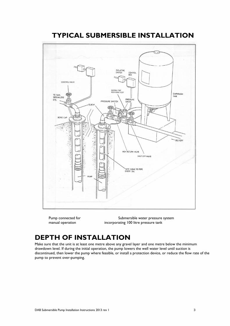
TYPICAL SUBMERSIBLE INSTALLATION
Pump connected for Submersible water pressure system
manual operation incorporating 100 litre pressure tank
DEPTH OF INSTALLATION Make sure that the unit is at least one metre above any gravel layer and one metre below the minimum
drawdown level. If during the initial operation, the pump lowers the well water level until suction is
discontinued, then lower the pump where feasible, or install a protection device, or reduce the flow rate of the
pump to prevent over-pumping.
DAB Submersible Pump Installation Instructions 2013 rev 1 4
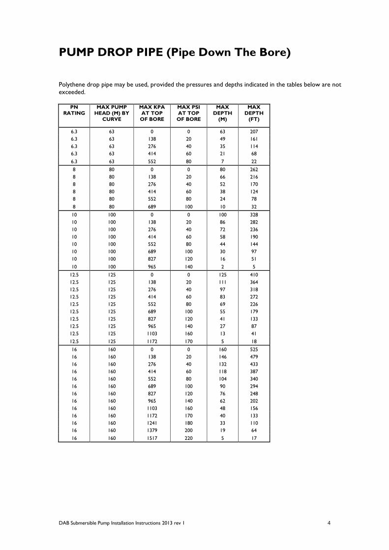
PUMP DROP PIPE (Pipe Down The Bore)
Polythene drop pipe may be used, provided the pressures and depths indicated in the tables below are not
exceeded.
PN
RATING MAX PUMP
HEAD (M) BY CURVE
MAX KPA AT TOP
OF BORE
MAX PSI AT TOP
OF BORE
MAX DEPTH
(M)
MAX DEPTH
(FT)
6.3 63 0 0 63 207
6.3 63 138 20 49 161
6.3 63 276 40 35 114
6.3 63 414 60 21 68
6.3 63 552 80 7 22
8 80 0 0 80 262
8 80 138 20 66 216
8 80 276 40 52 170
8 80 414 60 38 124
8 80 552 80 24 78
8 80 689 100 10 32
10 100 0 0 100 328
10 100 138 20 86 282
10 100 276 40 72 236
10 100 414 60 58 190
10 100 552 80 44 144
10 100 689 100 30 97
10 100 827 120 16 51
10 100 965 140 2 5
12.5 125 0 0 125 410
12.5 125 138 20 111 364
12.5 125 276 40 97 318
12.5 125 414 60 83 272
12.5 125 552 80 69 226
12.5 125 689 100 55 179
12.5 125 827 120 41 133
12.5 125 965 140 27 87
12.5 125 1103 160 13 41
12.5 125 1172 170 5 18
16 160 0 0 160 525
16 160 138 20 146 479
16 160 276 40 132 433
16 160 414 60 118 387
16 160 552 80 104 340
16 160 689 100 90 294
16 160 827 120 76 248
16 160 965 140 62 202
16 160 1103 160 48 156
16 160 1172 170 40 133
16 160 1241 180 33 110
16 160 1379 200 19 64
16 160 1517 220 5 17

DAB Submersible Pump Installation Instructions 2013 rev 1 5
PN
RATING
MAX PUMP
HEAD (M) BY CURVE
MAX KPA
AT TOP OF BORE
MAX PSI
AT TOP OF BORE
MAX
DEPTH (M)
MAX
DEPTH (FT)
20 200 0 0 200 656
20 200 138 20 186 610
20 200 276 40 172 564
20 200 414 60 158 518
20 200 552 80 144 472
20 200 689 100 130 426
20 200 827 120 116 379
20 200 965 140 102 333
20 200 1103 160 88 287
20 200 1172 170 80 264
20 200 1241 180 73 241
20 200 1379 200 59 195
20 200 1517 220 45 149
20 200 1655 240 31 103
20 200 1793 260 17 56
20 200 1931 280 3 10
Polythene drop pipe can be selected by reference to the pump curve and its suitability can be checked on site
by checking the maximum pressure read at the top of the bore reference to the maximum depth allowed.
An unstrained safety rope must be connected to all pumps suspended on polythene pipe. This line should be
fastened to the lifting hook of the pump. The other end should be fastened at the top of the bore casing or
bore cap. The safety rope should be affixed at three metre intervals by a suitable underwater tape with the rope
having some slackness between each interval to compensate for the expansion of the polythene pipe when
under load.
Care should be exercised to ensure that the polythene pipe is securely fastened to reliable fittings.
If galvanized steel drop pipe is used, it is best installed in three meter lengths to enable easy handling and all
threads should be treated against corrosion.
It may be necessary, as a safety precaution to install a non-return valve at the top of the bore. This is in addition
to the non-return valve fitted in the pump. This will assure a break down of the water hammer and
consequently a reduction of shocks on the hydraulic components (which occurs in any pump system)
immediately after each shutdown.
This non-return valve is mandatory where the pump heads (pressure at the top of the bore plus pump depth)
exceed 80 m (785 kPa or 262 ft) or where the pump is part of an automatic pressure system.
WIRING Wiring should conform to the requirements of local and national electrical codes. If in any doubt, contact your
Electricity Supply Authority.
CAUTION
The use of smaller cable than specified below may cause premature motor failure and will void the warranty.
Larger sized cables may be used.
The use of old drop cable or white flat is not recommended. Use water-proof cable only, i.e,
Aquaflex AQM rated for immersion to 100 m (500m immersion rated also available) obtainable from White
International.
The tables on the next page indicate the correct size electrical drop cable and maximum lengths to be used.

DAB Submersible Pump Installation Instructions 2013 rev 1 6
SINGLE PHASE 240 VOLT CABLE SELECTION
TESLA 3.2 4.4 5.9 8.2 10.5 15.3
240V MOTOR PSC kW (HP)
0.37 (0.5)
0.55 (0.75)
0.75 (1.0)
1.1 (1.5)
1.5 (2.0)
2.2 (3.0)
Metric
Cable
Stranding Area mm2 metres metres metres metres metres metres
7/0.50 1.5 94 67 49 36 29 19
7/0.67 2.5 174 123 91 67 53 36
7/0.85 4.0 279 197 146 106 85 58
7/1.04 6.0 417 296 218 159 126 87
7/1.35 10 701 496 366 268 213 147
7/1.70 16 1117 791 585 426 339 235
THREE PHASE 415 VOLT CABLE SELECTION
TESLA 1.5 1.8 2.3 3.3 4.2 5.7 8.0 9.6 13.5 16.8
415V MOTOR kW (HP)
0.37 (0.5)
0.55 (0.75)
0.75 (1.0)
1.1 (1.5)
1.5 (2.0)
2.2 (3.0)
3.0 (4.0)
4.0 (5.5)
5.5 (7.5)
7.5 (10.5)
Metric
Cable
Stranding Area mm2 metres metres metres metres metres metres metres metres metres metres
7/0.50 1.5 267 240 185 133 104 77 55 46 33 27
7/0.67 2.5 491 442 340 245 192 142 101 84 61 49
7/0.85 4.0 789 710 546 395 308 229 161 135 98 79
7/1.04 6.0 1180 1062 817 590 462 342 241 202 147 118
7/1.35 10 1982 1784 1372 991 775 575 405 339 246 198
7/1.70 16 3158 2843 2186 1579 1236 917 646 541 392 315

DAB Submersible Pump Installation Instructions 2013 rev 1 7
MOTOR DATA
TESLA
240V PSC MOTORS
kW HP AMPS AMPS OHMS OHMS CAPACITOR O/LOAD
Full Load Locked Rotor Run Winding Start Winding uF A
Black to Blue/Grey* Black to Brown*
0.37 0.5 3.4 9.2 8.8 18.8 16 4
0.55 0.75 4.8 15.8 5.6 13.5 20 5
0.75 1.0 6.5 20.8 3.5 6.7 25 7
1.1 1.5 8.9 32.0 2.5 5.4 35 10
1.5 2.0 11.2 41.4 1.9 5.0 40 13
2.2 3.0 16.2 50.2 1.6 3.7 60 20
TESLA
415VMOTORS
kW HP AMPS AMPS OHMS
Full Load Locked Rotor Across Any
Two Leads
0.37 0.5 1.8 6.8 35.0
0.55 0.75 2.0 8.4 25.6
0.75 1.0 2.6 13.0 17.3
1.1 1.5 3.6 14.8 13.0
1.5 2.0 4.6 19.8 8.9
2.2 3.0 6.2 27.3 6.0
3.0 4.0 8.8 40.5 4.2
4.0 5.5 10.5 58.8 3.3
5.5 7.5 14.5 79.8 2.35
7.5 10.0 18.1 86.9 2.0
* Resistances taken at motor leads.
CONNECTION TO THREE PHASE STARTERS
A direct on line starter incorporating thermal overload and fuses must be used with all three phase motors,
otherwise warranty will be void. Use of non approved fuses may not protect your motor and void warranty.
CHECK ROTATION OF BOTH SINGLE AND
THREE PHASE MOTORS
Both single and three phase motors connected to a supply for the first time may rotate in either direction. It is
therefore necessary to find out if the motor is rotating in the correct direction. Motor shaft rotates
anticlockwise viewed from the lead grommet end. Change rotation by reversing wires.
If rotation is to be checked on the surface, proceed as follows:
Pour clean water into discharge by holding the non-return valve open so that the shaft bearings and the
impellers become wet.
Turn on the power switch and check the shaft rotation is correct.
WARNING: The dry running should not exceed 2 to 3 seconds, otherwise seizing may occur due to inadequate
lubrication.
DAB Submersible Pump Installation Instructions 2013 rev 1 8
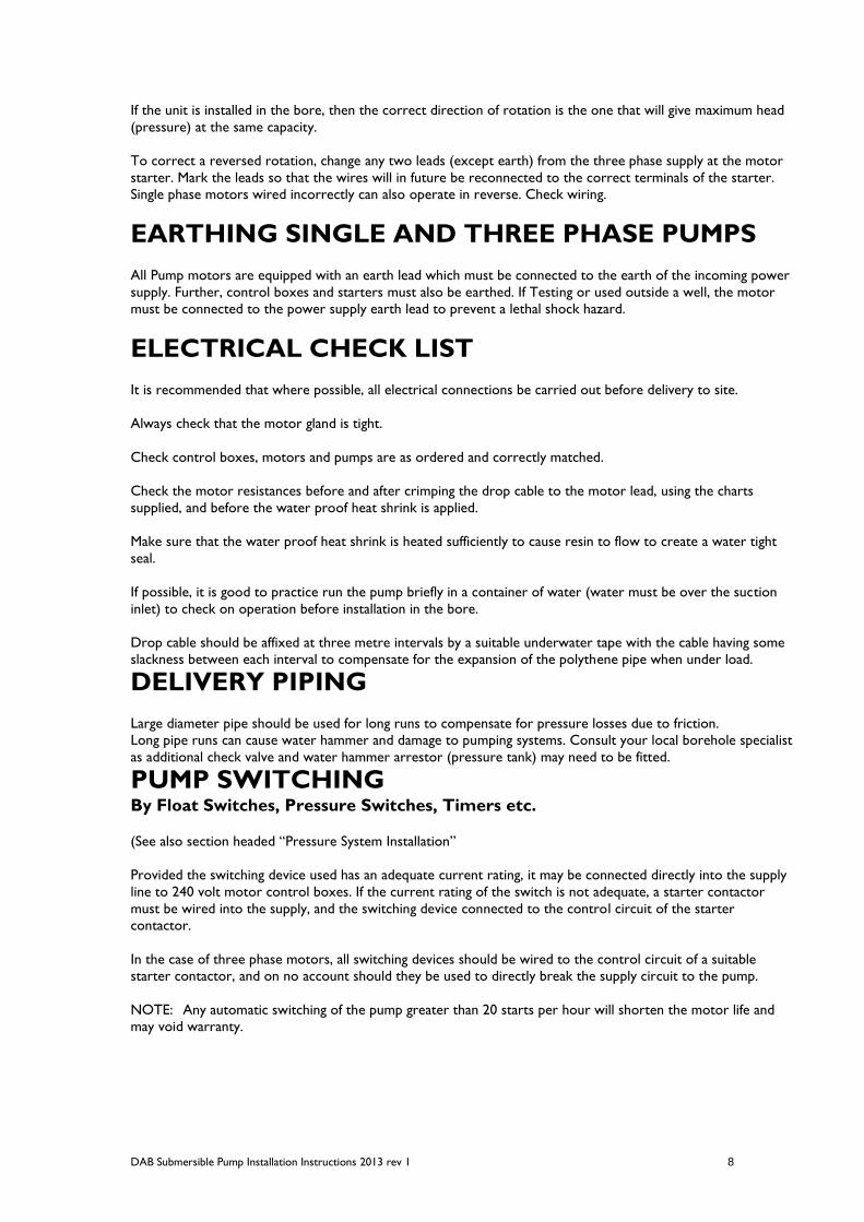
If the unit is installed in the bore, then the correct direction of rotation is the one that will give maximum head
(pressure) at the same capacity.
To correct a reversed rotation, change any two leads (except earth) from the three phase supply at the motor
starter. Mark the leads so that the wires will in future be reconnected to the correct terminals of the starter.
Single phase motors wired incorrectly can also operate in reverse. Check wiring.
EARTHING SINGLE AND THREE PHASE PUMPS
All Pump motors are equipped with an earth lead which must be connected to the earth of the incoming power
supply. Further, control boxes and starters must also be earthed. If Testing or used outside a well, the motor
must be connected to the power supply earth lead to prevent a lethal shock hazard.
ELECTRICAL CHECK LIST
It is recommended that where possible, all electrical connections be carried out before delivery to site.
Always check that the motor gland is tight.
Check control boxes, motors and pumps are as ordered and correctly matched.
Check the motor resistances before and after crimping the drop cable to the motor lead, using the charts
supplied, and before the water proof heat shrink is applied.
Make sure that the water proof heat shrink is heated sufficiently to cause resin to flow to create a water tight
seal.
If possible, it is good to practice run the pump briefly in a container of water (water must be over the suction
inlet) to check on operation before installation in the bore.
Drop cable should be affixed at three metre intervals by a suitable underwater tape with the cable having some
slackness between each interval to compensate for the expansion of the polythene pipe when under load.
DELIVERY PIPING
Large diameter pipe should be used for long runs to compensate for pressure losses due to friction.
Long pipe runs can cause water hammer and damage to pumping systems. Consult your local borehole specialist
as additional check valve and water hammer arrestor (pressure tank) may need to be fitted.
PUMP SWITCHING
By Float Switches, Pressure Switches, Timers etc.
(See also section headed “Pressure System Installation”
Provided the switching device used has an adequate current rating, it may be connected directly into the supply
line to 240 volt motor control boxes. If the current rating of the switch is not adequate, a starter contactor
must be wired into the supply, and the switching device connected to the control circuit of the starter
contactor.
In the case of three phase motors, all switching devices should be wired to the control circuit of a suitable
starter contactor, and on no account should they be used to directly break the supply circuit to the pump.
NOTE: Any automatic switching of the pump greater than 20 starts per hour will shorten the motor life and
may void warranty.
DAB Submersible Pump Installation Instructions 2013 rev 1 9
INITIAL STARTING
Before connecting the pump outlet pipe from the bore, bend and gate valve should be screwed into the top of
the bore cap as a pump valve.
With the gate valve just slightly open, start the pump.
NEVER START THE PUMP AT FULL FLOW FOR
THE FIRST TIME
Immediately the pump has been started, catch some of the discharge water in a large container and allow the
solids to settle out. If little or no sand appears, open the gate valve to 1/3 and pump until the water is clean.
For the first 10 to 20 minutes of operation, it is suggested to keep the gate valve only partially open, to maintain
a low flow which will prevent turbulence in the well near the pump and possible seizing of the pump due to
excessive sand in the water.
If excessive amounts of sand or other solids are being pumped, shut the pump down, and have the bore
attended to before restarting the pump.
Submersible pumps are not guaranteed against failure due to pumping sand. Pumping of sand of even very fine
small quantities will shorten the effective life of any pump.
NEVER OPEN THE GATE VALVE ABRUPTLY
as this may raise sand and deposits.
The pump should be run for a period of 30 minutes to check that it does not pump the bore dry.
This would be obvious by large fluctuations on the pressure gauge and the ammeter as the pump flow surges.
Continuing operation in this manner could cause serious damage to the pump and motor due to shock
pressures as the pump alternately takes up and loses the hydraulic load. This effect is generally referred to as
“snoring”.
If in doubt about the draw down level of the bore, the use of level controller is recommended. If probe type is
used, the probe should be located to switch the pump off when the bore water level drops within 1 metre of
the pump suction. The use of a high level probe to automatically turn the pump on is not desired, as a rapid
cycling of the pump could occur causing severe damage to the unit. Time clock or manual restart is
recommended. Alternatively a probeless control such as TESLA GUARDIAN can be used.
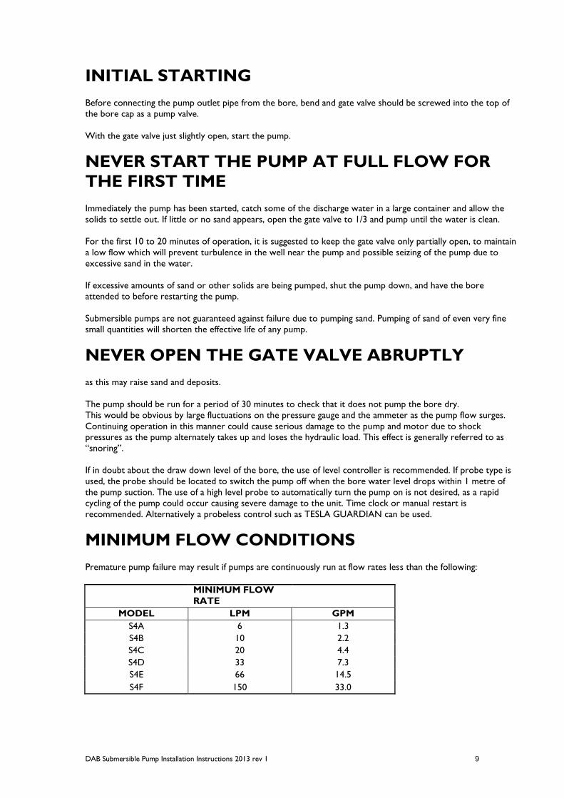
MINIMUM FLOW CONDITIONS
Premature pump failure may result if pumps are continuously run at flow rates less than the following:
MINIMUM FLOW
RATE
MODEL LPM GPM
S4A 6 1.3
S4B 10 2.2
S4C 20 4.4
S4D 33 7.3
S4E 66 14.5
S4F 150 33.0
DAB Submersible Pump Installation Instructions 2013 rev 1 10
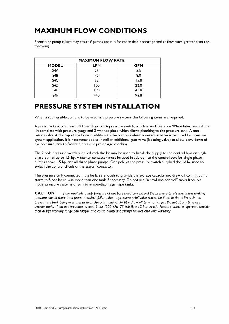
MAXIMUM FLOW CONDITIONS
Premature pump failure may result if pumps are run for more than a short period at flow rates greater than the
following:
MAXIMUM FLOW RATE
MODEL LPM GPM
S4A 25 5.5
S4B 40 8.8
S4C 72 15.8
S4D 100 22.0
S4E 190 41.8
S4F 440 96.8
PRESSURE SYSTEM INSTALLATION
When a submersible pump is to be used as a pressure system, the following items are required.
A pressure tank of at least 30 litres draw off. A pressure switch, which is available from White International in a
kit complete with pressure gauge and 3 way tee piece which allows plumbing to the pressure tank. A non-
return valve at the top of the bore in addition to the pump’s in-built non-return valve is required for pressure
system application. It is recommended to install an additional gate valve (isolating valve) to allow blow down of
the pressure tank to facilitate pressure pre-charge checking.
The 2 pole pressure switch supplied with the kit may be used to break the supply to the control box on single
phase pumps up to 1.5 hp. A starter contactor must be used in addition to the control box for single phase
pumps above 1.5 hp, and all three phase pumps. One pole of the pressure switch supplied should be used to
switch the control circuit of the starter contactor.
The pressure tank connected must be large enough to provide the storage capacity and draw off to limit pump
starts to 5 per hour. Use more than one tank if necessary. Do not use “air volume control” tanks from old
model pressure systems or primitive non-diaphragm type tanks.
CAUTION: If the available pump pressure at the bore head can exceed the pressure tank’s maximum working
pressure should there be a pressure switch failure, then a pressure relief valve should be fitted in the delivery line to
prevent the tank being over pressurised. Use only nominal 30 litre draw off tanks or larger. Do not at any time use
smaller tanks. If cut out pressures exceed 5 bar (500 kPa, 73 psi) fit a 12 bar switch. Pressure switches operated outside
their design working range can fatigue and cause pump and fittings failures and void warranty.

DAB Submersible Pump Installation Instructions 2013 rev 1 11
PUMP SERVICE CHART
THE TROUBLE IS? WHAT TO LOOK FOR
Overload protector trips Faulty pressure switch
Control box in sun or near heat source
Wrong control box being used
Defective control box
Hydraulic overload
Water logged pressure tank
Low voltage supply to motor
Excessive motor starts
No water delivered Broken pump shaft or coupling
Check valve installed backwards
Check valve stuck closed
Inlet screen clogged
Water level too low in well
Hole in delivery pipe below top of bore
Low water delivery Fittings stopping check valve opening fully
Pump rotation backwards
Water level too low in well
Discharge pipe clogged, corroded or ruptured
Pump installed too low in well and covered with
sand or other solids
Inlet screen partial clogged
Worn pump
Leak in outlet pipe below top of bore
Check valve stuck partially closed
Pump doesn't shut off Pipe ruptured
Defective or improperly adjusted pressure switch
Water level too deep for pump. Check selection
Pump is air or gas bound
Worn pump
Pipe obstruction
Pump needs adjusting
Pump starts and stops too often (i.e. more than 5
per hour)
Incorrect pressure switch, see pressure system
installation
Defective air valve or tank diaphragm
Pressure switch differential adjustment failure
Pressure tank is too small

DAB Submersible Pump Installation Instructions 2013 rev 1 12
PUMP SERVICE CHART con’t.
THE TROUBLE IS? WHAT TO LOOK FOR
Fuses blow but overload doesn't trip Supply cable too small
Hydraulic overload
Fuses too small
Fuse receptacle dirty or corroded
Power spike
Loose connection in fuse box
Defective incoming power leads
Excessive motor starts per hour
Earth wire connected to wrong control box
terminal
Cable insulation failure
Voltage too high or low
Electric shock from water pipe Defective (grounded) incoming power leads
Defective control box
Note: A motor down to earth or defective cable
will not cause a shock.
Earth wire connected to wrong control box
terminal
Pressure gauge oscillates, flow surges (snoring) Water level too low in the well. (Flow through
pump greater than flow into well)
Electrolysis on motor and pump Insufficient earth / earth leakage
Broken earth wire
NOTE: Always install borehole submersibles with ON/OFF switches and approved circuit breaker to protect
against motor damage and electrocution.
DAB Submersible Pump Installation Instructions 2013 rev 1 13
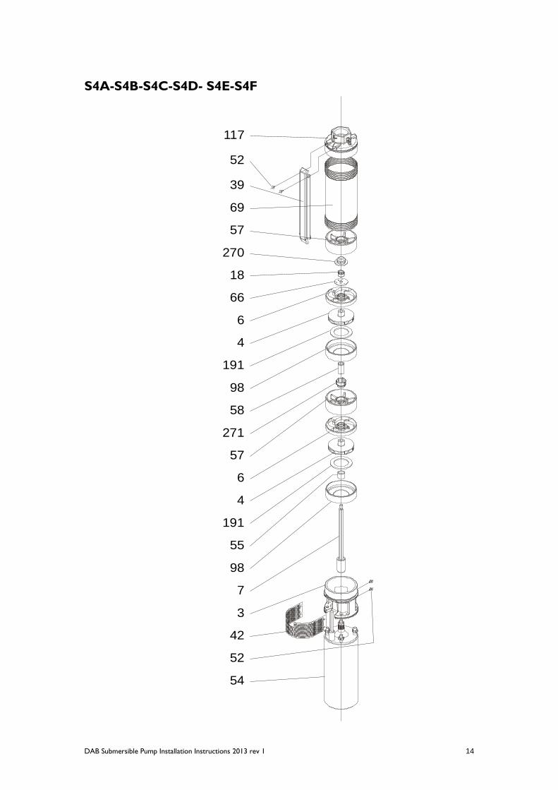
SERVICING AND MAINTENANCE INSTRUCTIONS
S4 SERIES
DISMANTLING
REMOVAL OF THE VALVE BODY (117): Unscrew the four screws (52), which hold the strainer and cable
guard. Remove the strainer (42) and cable guard (39). Loosen and remove the nuts and washers that attach the
pump to the motor and separate the pump and motor. Using an oil filter wrench grip the liner (69) and secure
the wrench in a vice. Use a spanner to unscrew the valve body (117) from the liner (69). N.B. The thread is left
hand. Take care to unscrew the components in the correct direction.
REMOVAL OF THE PUMP LINER (69): Grip the pump support (3) in a vice taking care not to damage the
support. Using an oil filter wrench, unscrew the liner (69) from the pump support (3). N.B. The thread is left
hand. Take care to unscrew the components in the correct direction.
DISMANTLING THE STAGES: Remove the upper support (57) complete with pilot bush (270), unscrew and
remove the nut (18) and the washer (66). Slide off each stage comprising of diffuser (6), impeller (4), wear ring
(191) and diffuser body (98). N.B. Some models have one or two intermediate supports (57) complete with
pilot bush (271) and shaft sleeve (58). With a texta mark these supports as the intermediate support and note
their position with respect to the pump stages. When all stages have been removed, the spacer bush (55) can
be slid from the shaft.
ASSEMBLY OF THE STAGES
Fit the pump shaft (7) onto the motor and ensure that the coupling engages fully. Fit the spacer bush (55) and
the support (3) over the shaft. Secure the support with the motor nuts and washers. Fit the first diffuser body
(98) on to the support, followed by the first wear ring (191) and the first impeller (4). Ensure that the impeller
metal neck ring fits inside the wear ring. Fit the first diffuser with the conical section of the diffuser’s internal
wear ring facing up. Repeat this for all stages taking care that impellers fit inside wear ring. Some models will
require their intermediate supports (57) complete with pilot bush (271) and shaft sleeve (58) to be fitted at the
locations that were previously marked. Fit the washer (66) and tighten the nut (18), and fit the upper support
(57) complete with pilot bush (270).
FITTING OF THE PUMP LINER (69): Grip the pump support (3) in a vice taking care not to damage the
support. Using an oil filter wrench, screw the liner (69) onto the pump support (3). N.B. The thread is left hand.
Take care to tighten the components in the correct direction.
FITTING OF THE VALVE BODY (117): Using an oil filter wrench, grip the liner (69) and secure the wrench in a
vice. Use a spanner to screw the valve body (117) into the liner (69). N.B. The thread is left hand. Take care to
tighten the components in the correct direction. Fit the strainer (42) and cable guard (39) using the four screws
(52).
DAB Submersible Pump Installation Instructions 2013 rev 1 14
S4A-S4B-S4C-S4D- S4E-S4F
117
52
39
69
57
270
18
66
6
4
191
98
58
57
6
4
191
55
98
7
3
42
52
54
271

DAB Submersible Pump Installation Instructions 2013 rev 1 15