
Installation and operating instructions for the KB-series · Read these installation and operating...
39
Installation and operating instructions for the KB-series KB 20 / 7 kW KB 40 / 13 kW Technical changes reserved 09/2013 Innovative Heating systems KB 45 / 24 kW KB 50 / 28 kW KB 75 / 38 kW SCHEER Heizsysteme & Produktionstechnik GmbH Chausseestraße 12-16 D-25797 Wöhrden Tel. +49 (0) 48 39 - 90 50 Fax +49 (0) 48 39 - 45 3 [email protected] www.scheer-heizsysteme.de
-
Upload
truongkhue -
Category
Documents
-
view
215 -
download
0
Transcript of Installation and operating instructions for the KB-series · Read these installation and operating...

Installation and operatinginstructions for the KB-series
KB 20 / 7 kW KB 40 / 13 kWTe
chni
cal c
hang
es re
serv
ed 0
9/20
13
Innovative Heating systems
KB 45 / 24 kW KB 50 / 28 kW KB 75 / 38 kW
SCHEERHeizsysteme & Produktionstechnik GmbH
Chausseestraße 12-16D-25797 WöhrdenTel. +49 (0) 48 39 - 90 50Fax +49 (0) 48 39 - 45 [email protected]
www.scheer-heizsysteme.de
Inhaltsverzeichnis
1. Warning and safety information 2. Operating principle of the KB-Series 4 2.1 Overview of the KB Series models 4 2.2 Construction of the KB Series 53. Components of the KB-Series 6 3.1 Oil filter-bleeder combination & Manometer 6 3.2 Oil pump motor 70 W with operation capacitor 7 3.3 Oil pump AL 35-C 9553-6 7 3.4 SCHEER Oil nozzles 8 3.5 Fan and controller board 8 3.6 Power-on & power-off delay timers 9 3.7 Air pressure switch 9 3.8 Ignition unit 9 3.9 Flame detector 10 3.10 Burner controller 10 3.11 Circulating pump 11 3.12 Three way valve for the version with storage tank loading 11 3.13 OPTIONAL: water heating via plate heat exchanger 114. Installation 12 4.1 KB-Series set up 13 4.2 Air supply 14 4.3 Exhaust gas routing 15 4.4 Water supply 16 4.5 Oil supply 17 4.6 Power connection 185. Commissioning 19 5.1 OPTIONAL: Service plug connector for the testing and setup of the KB series 19 5.2 Boiler temperature adjustment 21 5.3 Oil supply verification 22 5.4 Measure and adjust emission levels 236. Maintenance 24 6.1 Control the Condensate collector 25 6.2 Boiler cleaning 25 6.3 Oil filter replacement 25 6.4 Control the mixing cartridge 26 6.5 Replacement of the oil nozzle 27 6.6 Check the capacitor of the oil pump motor 28 6.7 Centrifugal fan cleaning 28 6.8 Control the exhaust emissions 297. Error diagnostics 308. Decommissioning & Storage 31 8.1 Prolonged Inactivity 329. Transport 3210. Disposal 3211. Circuit diagram of the control panel 3312. Electrical circuit diagram of the burner 3413. Exploded view & parts list 35
Table of Contents
2
Kabola Blue KB -Series

www.scheer-heizsysteme.de
2. Read and store the installation and operating instructionsRead these installation and operating instructions carefully and follow the instructions. These instructions guide contains the complete information about safety, installation, and setup and maintenance of the KB series.
Failure to follow these instructions can result in personal injury, fire or property damage. These instruction guide is part of the KB series. Store this manual near the KB-Series, so that in the future you may quickly consult it.
3. Qualified personelThe installation, commissioning and maintenance may only be performed by qualified persons.
Otherwise, damage may occur to persons or product. As part of training for you free in home SCHEER you obtain the necessary qualifications for working on the BE-KB-burner and the Handling of heating systems on ships.
4. Electrical work All electrical work must be performed by qualified personnel. Switch the system power supply OFF before wor-king on the KB series. Check the wiring when replacing components.
5. Prescribed use of the KB seriesThe KB-series will be used to produce hot water for space heating and optionally for heating fresh water. The model selection is based on a heat load calculation. The KB-series is not designed to heat the boiler room. Boiler and burner of the respective KB-series are perfectly matched for optimal performance and may not be modified. Example: Burner BE-KB 40 is matched -and should only be installed- to boiler KB 40.
6. Diesel fuel or fuel oil ELThe KB-series may only be operated with diesel or fuel oil EL (standard and low sulfur) according to DIN EN 590. It is designed solely for operation with these fuels. With other fuels there may be injuries of persons or property due to explosions or malfunctions of the burner.
7. Use genuine spare partsReplace components of the KB series only with genuine spare parts from SCHEER. The components are specially adapted to the requirements of the KB series. Should you use parts from other manufacturers, the proper func-tion can not be assured and the guarantee expires. When placing an order please indicate the type designation and serial number. Both can be found on the type plate of the boiler and the burner. This will allow us to supply you with the suitable replacement parts.
8. Annual MaintenanceHave the KB series annually cleaned and maintained by qualified staff in order to enable trouble-free and energy efficient operation of the KB series. The maintenance procedure is described in Chapter 5.
Possible material damage if ignored
possible light and medium injury if ignored
severe or life-threatening injury or possible death if ignored
probable life-threatening injury or death if ignored
ATTENTION
CAUTION
WARNING
DANGER
1. Meaning of the warning and caution signs
1. Warning and safety information
3
Kabola Blue KB -Series

www.scheer-heizsysteme.de
At initial startup, or in case of voltage drop or voltage interruption, the power-on delay delays the burner start-up by 120 s. In case of interruption during the operation the power-on delay and the post-puge period of the fan occur in parallel.
2.1 Overview of the KB Series
2. Operating principle the KB series
heat requirement or T_boiler < T_min
signal to the burner controller
oil preheater ON (preheating time) to
about 65°C
T_oil = 65°C?
no
yes
fan OFF
green indicator lamp at the burner
yes
no
no
no
yes
yes
the thermostat of the oil preheater outputs signal to
the burner controller
post-purge period (120s)
all other components turned OFF
fault shutdown
1. malfunction
ignition unit turned ON
(Pre-ignition time)
fan ON(pre-purge
period)
air pressure switch turned
ON
possibility that combustible
residues ignite and blow out
oil pumpsolenoid
valve open
oil pump motor turned ON
concentration and venting of the oil
heat the water in the boiler until
T_boiler=T_max or until the heat demand
is terminated
illuminates
reached minimalair pressure?
burningprocess
present?
oil supply ON
KB 20 KB 40 KB 45 KB 50 KB 75Operating performance kW 7 13 24 28 38Dimensions (H / W / D) cm 40 / 38 / 52 42 / 38 / 62 44 / 38 / 64 52 / 43 / 70 52 / 43 / 70Weight (standard / combi) kg 65 / - 75 / 80 80 / 85 90 / 95 115 / 120Efficiency % 92 93 93 94 94Water heating plate heat exchanger - Option (combi)
Water capacity of the boiler Liters 8.5 17.5 20.0 23.0 37.0Fuel Diesel / Heating oil according to DIN EN 590Oil flow L/h 0.69 1.27 2.35 2.75 3.73Oil nozzles 0.18 - 80° SC 0.25 - 80° SC 0.40 - 60° SC 0.50 - 60° SC 0.65 - 60° SCExhaust temperature °C
°F170 - 220 338 - 428
150 - 200 302 - 392
145 - 205 293 - 401
145 - 200 293 - 392
140 - 190 284 - 374
Exhaust pipe connections - Ø mm Ø 80Exhaust pipe - Ø mm Ø 50 Ø 80
4
Kabola Blue KB -Series

www.scheer-heizsysteme.de
2.2 Construction of the KB Series
control panel oil filter-blee-der combination
power ON delay timer
power OFF delay timer
controller board for the fan speed
two-stage fanoil pump flame detector
air pressure switch
burner controller
circulating pump
three way valve
oil pump motor
ignition unit
7-poleburner connection
mixing cartridge
connection for thefilling and emptyingof the boiler
shown is a KB 20/7 kW with storage tank connection
Pipe connection
(mountable on the connection for the filling and emptying of the boiler)
5
Kabola Blue KB -Series

www.scheer-heizsysteme.de
This chapter presents the components of KB-series and their functionality. An exploded drawing and spare parts list can be found on pages 35 and 36 .
The oil filter-bleeder combination cleans the oil and keeps it air-free.The trouble-free operation of the burner is only achieved with clean, air-free oil.
Use only oil filter and bleeder made of metal! Plastic parts are not permitted for fire safety reasons.
The KB-Series are delivered with the oil filter-bleeder combination made of metal, as shown in the figure. The oil filter contains an ultra-fine filter insert. The oil bleeder vents the oil automatically.
If you use any other oil filter or bleeder, please note the followingminimum requirements:
1. Oil filter
• completely made of metal
• suitable for single pipe systems
• an ultra-fine filter insert
2. Oil bleeder
• completely made of metal
• automatic bleeder
The underpressure manometer shows the underpressure in the supply flow to the oil pump.
The system is running optimally in the underpressurerange from 0.0 to -0.3 bar. A filter change is recommended for va-lues between -0.3 and -0.5 bar, while even greater underpressure may cause malfunctions and an increased pump wear should be expected.
3. Components of the KB-Series
3.1 Oil filter-bleeder combination
The installation of the oil filter-bleeder combination is presented in Section 4.5
Underpressure manometerArt. No. 040126
Oil filter-bleeder combination made of metal Art. No. 040513
6
Kabola Blue KB -Series

www.scheer-heizsysteme.de
Check the capacitor at every maintenance. If the capacitance deviates by more than 5 % (smaller 2.85 µF) then the capacitor has to be replaced. The maintenance procedure for the capacitor is described in section 6.4.
3.2 Oil pump motor 70 W with operation capacitor
3.3 Oil pump
Voltages below 200 V may lead to stoppage of the oil pump motor!
oil pump motorSupply voltage 220 to 250 V AC (50/60 Hz)Current consumption 0.54 APower 70 WSpeed 2810 min-1 at 50 Hz
3200 min-1 at 60 HzOperation capacitor temperature resistant up to 100 °C (212 °F)
3 µF, 420 V AC
Oil pump motorArt. No. 015138
•
Replace the oil pump motor only with a genuine spare part. This oil pump motor has a stator with a double enamelled wire, especially suitable for the marine sector.
Only use genuine spare parts!ATTENTION
Oil pumpPressure range 4 to 25 barViscosity range 2 to 12 mm²/sForward / return flow pressure respectively max. 2 barSpeed max. 3600 min-1
Operating temperature 0 to 60 °C(32 to 140 °F)
Oil pumpArt. No. 011236
• Only use genuine spare parts!
You can find the model-depen-dent oil pressure directly on the label on the burner.
ATTENTION
Under no circumstances should you replace the oil pump by another oil pump type. The oil pump is specially configured for use in the BE-KB-burner. Use only the genuine oil pump from SCHEER.
7
Kabola Blue KB -Series

www.scheer-heizsysteme.de
3.4 SCHEER oil nozzles
3.5 Centrifugal fan & Controller board
SCHEER oil nozzles
SCHEER oil nozzles Art. No.
KB 20 0.18 - 80° SC 022276KB 40 0.25 - 80° SC 022277KB 45 0.40 - 60° SC 022368KB 50 0.50 - 60° SC 022370KB 75 0.65 - 60° SC 022373
•
Use only genuine SCHEER oil nozzles! A trouble-free operation can only be ensured through the use of genuine SCHEER nozzles. They are specially configured and tested in a flow range with only 5% toleran-ce.
Only use genuine spare parts!ATTENTION
The nozzle replacement is described in section 6.2
Centrifugal fanArt. No. 015112
The centrifugal SCHEER 2-stage fan is a powerful fan that is used in all models of the KB series. The fan through its centrifugal operation is essentially prohibiting dust and dirt particles to enter the airway.
The fan is in constant communication with the controller board. Through simple use of the controller board, the speed of the fan and thus an optimum combustion quality can be adjusted.
The operation is described in Chapter 5.
Centrifugal fanSupply voltage 230 V AC (50 Hz)Power input 135 W (depending on the air flow)Speed max. 8500 min-1 (depending on the air flow)Air flow max. 190 m³/hBack pressure max. 3200 Pa and respectively 32 mbar
Controller board
Art. No.
KB 20 015374KB 40 015376KB 45 015377KB 50 015378KB 75 015379
8
Kabola Blue KB -Series

www.scheer-heizsysteme.de
3.7 Air pressure switch
3.8 Ignition unit
3.6 Power-on & power-off delay timers
power-off delay timer120 secondsArt. No. 070553 (blue)
power-on delay timer120 seconds Art. No. 070555 (yellow)
The power-on delay (marked by a yellow dot) delays the burner start-up for 120 seconds after a power interruption (switching over from on-board power to mains power).
The power-off delay (marked by a blue dot) ena-bles at the end of the heat demand a post-purge period of the fan for 120 seconds.
The air pressure switch controls the burner fan pressure and is con-nected to the solenoid valve of the oil pump.
The solenoid valve opens only when there is sufficient air pressure, so that the combustion process can start.
When the air pressure is insufficient, the air pressure switch prevents the leakage of oil into the combustion chamber.
Thus avoiding the contamination of the combustion chamber from oil and the possibility of explosions at the next start-up of the bur-ner.
air pressure switchArt. No. 015180
The SCHEER ignition unit is an electronic ignition unit for intermittent igni-tion between 2 electrodes. Low weight and small dimensions, due to the high operating frequency, makes the SCHEER ignition unit very suitable for modern compact burners. Connections with a plug on the primary side and secondary side make installation and service quick and simple.
ignition UnitArt. No. 010276
9
Kabola Blue KB -Series

www.scheer-heizsysteme.de
3.10 Burner controller
3.9 Flame detector
The flame detector evaluates the flames based on their fli-cker frequency. The SCHEER flame detector is more efficient than a simple light flame detector.
Through the integrated frequency-interference suppression neither Light-resembling radiation (e.g. glowing surround-ings) nor constant frequencies (e.g. fluorescent lamps) are recognized as a flame.
Unwanted influences of flame detection are thus avoided.
Operating status display:
LED off Flame detector inactiveLED flashes Safety testing is conducted, flame detector is active, no flame detected.LED is lit Safety testing is conducted, flame detector active, flame detected.
No adjustments are required for the SCHEER flame detector at initial commissioning or maintenance!
flame detectorArt. No. 020064
The burner controller takes over the operation/start-up and supervision of the burner. If a fault occurs during the start or burning process, the burner controller goes to a fault shutdown.
Fault ResponsePower failure RestartLoss of flame during operation RestartExternal light on burner startup Fault shutdown No flame after the safety period Fault shutdown
Control program by fault shutdown1. Triggers the fault shutdown in the burner controller2. Immediate shutdown (<1 s) of all relevant for the oil supply components
(solenoid valve, oil pump motor, oil preheater, igniter)3. Interruption of the oil supply, and termination of the burning process4. Fault indicator in shutdown reset button lights-up red
Under Troubleshooting on page 30 possible causes of fault shutdown and solutions are listed.
Low voltage detectionA separate circuit in the burner controller ensures that at voltages below 165 V AC the burnerstart-up is prevented or -without the release of oil- a fault shutdown is triggered.
burner controllerArt. No. 020100
10
Kabola Blue KB -Series

www.scheer-heizsysteme.de
3.12 Three way valve for the version with storage tank loading
3.13 OPTIONAL: water heating via plate heat exchanger
3.11 Circulating pump
three way valveArt. No. 10-J004
The three way valve is provided with an electric drive. It is used for the two-point control as a mixer or distribution in the hot water system. The three way valve is controlled either by the boiler thermostat or by a room thermostat. You can switch via a lever between automatic and manual mode (AUTO / MAN).
Switch the lever to MAN when filling, venting and draining. Through the MAN position, the valve tappet is in the centre position. The water can then flow out to both outlets.
The three-stage circulating pump is responsible for the cir-culation of the boiler water and is mounted in the return flow of the boiler water.
The venting of the water system of the circulating pumpis described in Section 4.4.
circulating pumpArt. No. 9-I053
Via the plate heat exchanger, the water in the boiler heats the cold fresh water, which is then available as heated water.
Water heating via a plate heat exchanger can be offered as an option for models KB 40, KB 45, KB 50 and KB 75.
These models have the additional Combi e.g. KB 40 Combi.
11
Kabola Blue KB -Series

www.scheer-heizsysteme.de
This chapter describes the steps required for the installation. The commissioning is described in Chapter 5.
The connections of the KB series are labelled in the following figure:
Power connection to power plug
230 V
Flow(indicated
by a red tape)Ø 22 mm
Return(indicated by a blue tape)
Ø 22 mm
Exhaust connection(Ø 80 mm)
Connection of oil line from the oil tank
4. Installation
12
Kabola Blue KB -Series

www.scheer-heizsysteme.de
• Place the KB series in a dry room.
• Watch out for a horizontal and stable surface.
• Ensure the proper ventilation of the room and burner (see section 4.2).
• Secure the KB series against slippage, for example with bolted angle profiles.
• Keep a minimum distance of 250 mm from the back wall for the exhaust system.
• Use a grounded 230 V outlet for connecting the KB series to the on-board power supply.
Use a grounded 230 V outlet for connecting the KB series to the on-board power supply.
The KB-series should be fixed on the base with four M5 screws. The spacing x is given depending on the model:
KB 20 KB 40 KB 45 (KB 50) KB 75x [mm] 147 264 285 n.v. 345
•
Do not store any flammable and / or gaseous substances in the installation of the KB series. That could lead to explosions through the flame in the burner. As a result, persons in the vicinity may be seriously injured.
Danger of explosion!
Spacing x of the fastening holes
4.1 KB-Series set up
WARNING
13
Kabola Blue KB -Series
www.scheer-heizsysteme.de
4.2 Air supply
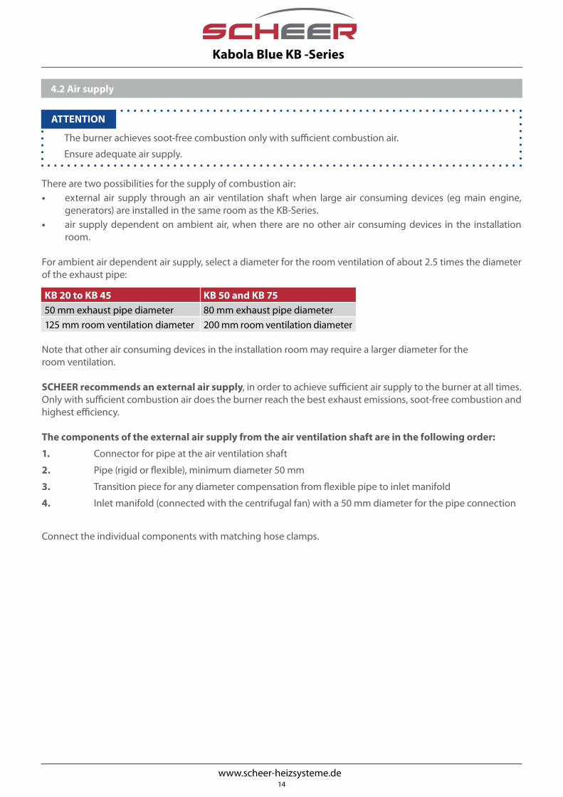
There are two possibilities for the supply of combustion air:• external air supply through an air ventilation shaft when large air consuming devices (eg main engine,
generators) are installed in the same room as the KB-Series.• air supply dependent on ambient air, when there are no other air consuming devices in the installation
room.
For ambient air dependent air supply, select a diameter for the room ventilation of about 2.5 times the diameter of the exhaust pipe:
Note that other air consuming devices in the installation room may require a larger diameter for the room ventilation.
SCHEER recommends an external air supply, in order to achieve sufficient air supply to the burner at all times. Only with sufficient combustion air does the burner reach the best exhaust emissions, soot-free combustion and highest efficiency.
The components of the external air supply from the air ventilation shaft are in the following order:
1. Connector for pipe at the air ventilation shaft
2. Pipe (rigid or flexible), minimum diameter 50 mm
3. Transition piece for any diameter compensation from flexible pipe to inlet manifold
4. Inlet manifold (connected with the centrifugal fan) with a 50 mm diameter for the pipe connection
Connect the individual components with matching hose clamps.
•
The burner achieves soot-free combustion only with sufficient combustion air.
Ensure adequate air supply.
ATTENTION
KB 20 to KB 45 KB 50 and KB 75 50 mm exhaust pipe diameter 80 mm exhaust pipe diameter 125 mm room ventilation diameter 200 mm room ventilation diameter
14
Kabola Blue KB -Series

www.scheer-heizsysteme.de
4.3 Exhaust gas routing
•
• The entire exhaust system must be made of stainless steel in order to withstand the high exhaust gastemperatures of up to 220 °C (428 °F) and corrosive ingredients of the exhaust gas.
• Outdoors the exhaust gas routing must be double-walled. Otherwise, condensate may form due to therapid cooling.
Risk of corrosion!
• Risk of burns! The exhaust gas and accordingly the exhaust system is heated up to 220 °C (428 °F)! Con-tact with skin can cause severe burns. Insulate throughout the exhaust system with heat resistant material, in areas reachable by body parts.
• Danger of explosion! If you include an blocking device in the exhaust system, it is then necessary to use a contact switch that is connected to the burner.
Emission-related information for the KB-Series KB 20 KB 40 KB 45 KB 50 KB 75
Exhaust temperature °C °F
170 - 220 338 - 428
150 - 210 302 - 410
145 - 205 293 - 401
145 - 200 293 - 392
140 - 190 284 - 374
Exhaust pipe connection-Ø at the boiler mm Ø 80Exhaust pipe-Ø mm Ø 50 Ø 80Muffler recommended no yes
ATTENTION
WARNING
HINT: Condensate may accumulate in the exhaust system when the exhaust gas temperature is low.
You can also use an existing exhaust gas routing. Should this have a larger exhaust pipe diameter than the requi-red, drag a flexible exhaust pipe with the diameter required in the existing exhaust gas routing. • The components of the exhaust gas routing are, starting from the boiler:
• Condensate collector, the lowest point of the exhaust system
• for 50 KB and 75 KB SCHEER recommends a silencer
• Exhaust pipe flexible or rigid (note the in the table specified exhaust pipe diameter)
• Through-hull and deck path, depending on the outlet direction of the exhaust gases
• for vertical outlet: double-walled chimney
The outlet of the exhaust gases can be passed vertically through a chimney or horizontally via a through-hull fitting. • Use the vertical outlet for sailing vessels and high-seas ships as large heeling and water overflow may occur.
• Connect the exhaust pipe on the deck pass with the inner tube of the double-walled chimney.
• Install a rain protection cap at the end of the chimney to prevent the entry of water into the exhaust system. • Use the horizontal outlet for motor vehicles and vessels in inland waterways. The heeling occurring here is
much smaller than in the above situations.
Connect the exhaust pipe to a double walled through-hull at a sufficient height above the water line.
Install a gooseneck in front of the through-hull of the exhaust system. In doing so, you prevent the penetration of water into the exhaust system.
15
Kabola Blue KB -Series

www.scheer-heizsysteme.de
Pay attention to the following when installing the flow and return line:
• The flow is marked with red tape and is under the return line (see the figure on page 12).
• The return is marked with blue tape and is located above the flow (see the figure page 12).
• Lay the lines so that the KB series remains accessible for maintenance.
• Ensure adequate ventilation of the boiler. Pay particular attention to areas where air can collect.
• Install a venting facility if the lines of the boiler do not go straight upwards.
• For the connection to the optional plate heat exchanger please refer to the manufacturer‘s instructions.
For the filling and venting of the heating system through the pipe connec-tion, proceed as follows:
1. Make sure that the KB series is turned off
2. Remove the cover
3. Connect the water hose with the supplied grommet
4. Loosen the connecting nut
5. Open the pipe valve
6. Fill the system slowly with water until the system‘s pressure manome-ter indicates a pressure of 2 bar.
7. Tighten the connecting nut
8. Vent the heating system
9. If the water pressure has dropped, top up with water, until 2 bar are reached again.
10. Let the circulating pump run for about 5 minutes.
11. Turn off the circulating pump.
12. Check the water pressure. If the pressure has dropped, repeat the steps from step 6.
13. Disconnect again the water hose. The system is now filled.
•
• The operating pressure must not be lower than 0.5 bar when cold or higher than 2.5 bar when warm.
• You can also fill the heating system with a suitable cooling fluid (pH 8.5) specifically designed for heating systems.
Bleed the circulating pump as follows:
1. Make sure that the circulating pump is receiving power and turned on.
2. Check that the rotor of the circulating pump is free to rotate - to do this, turn the rotor by hand.
3. Loosen the screw on the front of the circulating pump with a slotted screwdriver by 1/2 to 1 turn.
4. Wait until only water comes out of the screw opening.
5. Tighten the screw again. The circulating pump is now air-free.
Venting the circulating pump
4.4 Water supply
ATTENTION
Components of the pipe connectionA
B
C
DE
C
D
D
E
B
A
16
Kabola Blue KB -Series
www.scheer-heizsysteme.de
•
The fault-free operation of the burner can only be guaranteed with clean, air-free oil .
• Pay attention to the flow and return direction when connecting the oil pipes. The flow directions are indicated by arrows on the oil pump and the oil bleeder.
• Use oil filter and oil bleeder made of metal, only! Plastic parts are not permitted for fire safety reasons.
4.5 Oil supply
ATTENTION
Danger of explosion!
With improper installation of the oil bleeders it is possible that the explosions in the burner may result in serious injury of persons standing nearby !
• Attach the oil bleeder to the designated holder on the right side of the boiler (see illustration below). If this is not possible due to space limitations, mount the oil bleeder at least 30 cm higher than the oil pump.
• Install at least 50% of the oil line length ascending towards the oil bleeder.
WARNING
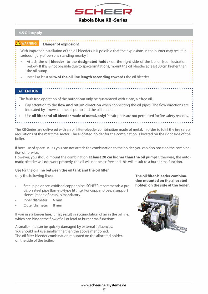
The KB-Series are delivered with an oil filter-bleeder combination made of metal, in order to fulfil the fire safety regulations of the maritime sector. The allocated holder for the combination is located on the right side of the boiler.
If because of space issues you can not attach the combination to the holder, you can also position the combina-tion otherwise.However, you should mount the combination at least 20 cm higher than the oil pump! Otherwise, the auto-matic bleeder will not work properly, the oil will not be air-free and this will result to a burner malfunction.
Use for the oil line between the oil tank and the oil filter,only the following lines:
• Steel pipe or pre-oxidised copper pipe. SCHEER recommends a pre-cision steel pipe (Ermeto-type fitting). For copper pipes, a support sleeve (made of brass) is mandatory.
• Inner diameter 6 mm• Outer diameter 8 mm
If you use a longer line, it may result in accumulation of air in the oil line,which can hinder the flow of oil or lead to burner malfunctions.
A smaller line can be quickly damaged by external influences.You should not use smaller line than the above mentioned.The oil filter-bleeder combination mounted on the allocated holder, on the side of the boiler.
The oil filter-bleeder combina-tion mounted on the allocated holder, on the side of the boiler.
17
Kabola Blue KB -Series

www.scheer-heizsysteme.de
• Electrical work on 230 V systems shall be performed only by qualified personnel!
• Make sure that the system is not live before you start connecting the KB series.
Danger of electric shock!
Check the following prerequisites for the operation of the KB-series on the on-board power supply:
• The 230 V power must have the same quality as the normal (onshore) mains-power.
• The power outlet used must be grounded.
Once these prerequisites are fulfilled, you can connect the KB series:
1. Insert the power plug of the control panel into the grounded power outlet.
2. Check with the service plug connector the correct phase polarity of the voltage (see section 5.1). Correct pha-se polarity is indicated by an illuminated indicator light.
3. If the indicator light of the service plug connector does not illuminate, turn the power plug around. Check that the indicator light is illuminated.
4.6 Power connection
DANGER
18
Kabola Blue KB -Series

www.scheer-heizsysteme.de
Danger of explosion!
Explosions in the burner may result in serious injury of persons standing nearby !
• Make sure that the burner is fixed to the boiler in order to prevent the inflow of air into the combustion chamber and thereby to hinter explosions.
• Make sure that the oil bleeder is mounted on the side of the boiler in the provided holder.
5. Commissioning
5.1 OPTIONAL: Service plug connector for the testing and setup of the KB series
WARNING
Service plug connector for the fan and controller boardArt.-Nr. 73010
Once you connect the service plug connector for the fan and controller board to the burner plug, the indicator light illuminates when the voltage in-phase is. If the indicator light does not illuminate, turn the power plug by 180°.
With a direct connection to the oil pump motor or fan motor, you can check the function of the oil pump motor and the oil pump and listen for sounds that indicate faulty bearings.
If the oil supply is disrupted (e.g. tank is empty), you can fix this through the direct access to the oil pump motor and put it back into service.Only allowed for small oil line lengths.
3
2
1
19
Kabola Blue KB -Series

www.scheer-heizsysteme.de
5.1 OPTIONAL: Service plug connector for the testing and setup of the KB series (continued)
In case the fan controller does not allow a burner start-up because of a defect or excessive deviations in fan speed (see performance data on the burner), please connect the service plug connector for the fan and controller board on the fan and the controller board.You can now correct the fan speed on the control board and can also preset a new control board.
4
ATTENTION: The pug of the service plug connector connected on the fan should ONLY be upwards connec-ted. The plug will also fit otherwise but the setup will not work and the fan (and possibly other parts) may be damaged.
Through the direct control of the ignition unit you can make the function of the transformer audible.
If you remove the mixing cartridge, and connect di-rectly the ignition cable to the transformer, you can make the ignition spark visible.
5
20
Kabola Blue KB -Series

www.scheer-heizsysteme.de
Set the boiler temperature through the control panel. The control panel ensures the power supply to the burner, the circulating pump and the 3-way valve. Furthermore, a temperature sensor is also connected to the control panel and extends into the boiler thereby measuring the boiler water temperature.
Description of the elements on the control panel:
Fuse holder with glass fuse 8A, 230V. Main switch Display for the status and temperature of boiler Adjustment knob for the boiler temperature Reset button for the limit thermostat.
The maximum boiler temperature is set using the adjustment knob D:
1. Press the adjustment knob D and turn it until the desired temperature is displayed on the display C.
2. When released, the set temperature is stored and the display returns to the current boiler temperature.
The reset button E resets the limit thermostat.
The display shows the status of the boiler next to the boiler temperature:
Status Description1 Heat demand present 3 Post-running of the circulation pump is active. 4 Boiler is kept warm (hot water comfort at your disposal) A Low voltage
Control panel Art.-No. 51-001
5.2 Boiler temperature adjustment
ABCD
E
A
B
C D E
D C
E
21
Kabola Blue KB -Series

www.scheer-heizsysteme.de
1. Open the stop valve of the oil tank.
2. Open the stop valve of the oil filter.
3. Connect the service plug connector to the oil pump motor (see section 5.1).
4. Let the oil pump run for about 5 minutes. The oil is bled through the oil bleeder, without the burner running.
5. Check the underpressure between the oil bleeder and the oil pump with the built-in underpressure manometer. The system is running optimally in the underpressure range of 0 to -0.3 bar. SCHEER recommends a filter change for values between -0.3 and -0.5 bar. Even greater underpressure may cause malfunctions and an increased pump wear should be expected.
6. The oil pressure of the oil pump has already been set by SCHEER. It is not required to check for the oil pressure of the oil pump.
7. Remove the service plug connector from the oil pump motor.
8. Re-connect the genuine oil pump connector.
•
The fault-free operation of the burner can only be guaranteed with clean, air-free oil.
ATTENTION
5.3 Ölversorgung überprüfen
Danger of explosion!
Explosions in the burner may result in serious injury of persons standing nearby !
• Make sure that the burner is fixed to the boiler in order to prevent the inflow of air into the combustion chamber and thereby to hinter explosions.
• Make sure that the oil bleeder is stably mounted in the provided holder on the boiler. If this is not pos-sible due to space limitations, mount the oil bleeder at least 30 cm higher than the oil pump. If the oil bleeder is not mounted higher than the oil pump, the oil can not bled and this can result in explosions.
WARNING
22
Kabola Blue KB -Series

www.scheer-heizsysteme.de
5.4 Abgaswerte messen und einstellen
1. Turn the burner on at the main switch of the control panel.
2. After a preheating time of the oil preheater, the burner goes into operation.
3. Turn the burner on and off, 3 times in a row. Always include the post-purge period of 120 s! By switching ON and OFF, any air is removed from the nozzle head. The air can lead to fluctuations in throughput and thus distort the measurement result.
4. Wait until the boiler has reached a minimum temperature of 60 °C (140 °F). The boiler is then in steady condition.
5. Connect the flue gas analyser to the measurement port in the exhaust system behind the boiler.
6. Adjust the fan speed using the fan controller board:
7. Close carefully the measurement port after the analysis.
The adjustment of the fan speed and thereby the adjustment of the CO2 value is also described on the controller board.
•
• It is essential to adjust the fan pressure during the initial commissioning!• The default fan pressure is only an initial setting. • The CO2 level is critical. You can find the required CO2 value on the burner.
ATTENTION
a. Hold down the + and S buttons for approximately 5 s
b. Indicator + flashes and indicator S illuminates
c. Adjustment mode can be now accessed
d. Adjust the fan speed by pressing + or -. Pay attention to the measured CO2 value. The required CO2 level is indicated on the burner.
e. Indicator S flashes fast until the speed adjustment is completed.
f. Save the set value by pressing the S key.
g. Indicator + illuminates, operating setting completed
Controller board, with the description of the fan speed adjustment
23
Kabola Blue KB -Series

www.scheer-heizsysteme.de
• Risk of slipping due to leaking or dripping oil. Wipe or collect the oil.
• Possible skin irritation from contact with oil. When working with oil wear safety gloves.
• Possible respiratory irritation due to dust inhalation while cleaning boiler. Ensure sufficient ventilation.
•
• Use only genuine spare parts. These are specially designed for the KB series. With the use of other replace-ment parts no warranty (statutory liabilities and rights) can be given and the guarantee expires.
• When placing an order please indicate the model and serial number of your KB-Series. These can be found on the right side of the boiler and the burner.
• In Chapter 13, you can find an exploded view of the KB series and the spare parts list.
6. Maintenance
ATTENTION
CAUTION
Prepare the KB-Series for the maintenance as follows:
1. If the burner is in operation, cancel the heat demand.2. Wait for the post-purge period with a 120 s duration.3. Turn off the KB-Series with the main switch on the control panel.4. Disconnect the plug from the 7-pin connector to the burner. The power supply of the burner is now inter-
rupted.5. Disconnect the plug of the control panel from the power outlet. The power supply of the boiler is now inter-
rupted.6. Dismantle the burner including the burner door from the boiler. To do this you should unscrew the door
knobs.7. The steps for cleaning the boiler and for the burner maintenance, are shown in the following sections.8. After the cleaning, mount again the burner to the boiler.9. Proceed with the recommissioning as described.
Maintenance intervalCondensate collector occasionallyBoiler cleaning every two yearsBurner maintenance every two yearsControl the exhaust emissions every two years
Oil filter replacement recommended when the underpressure manometer indicates underpressu-re greater than -0.3 bar
Fan cleaning after some years of operation
24
Kabola Blue KB -Series

www.scheer-heizsysteme.de
Change the oil filter and the filter cartridge only when the underpressure is too high. If the underpressure displayed on the underpressure manometer is greater than -0.3 bar, this means that the oil filter is clogged and needs to be renewed:
• The system is running optimally in the underpressure range of 0 to -0.3 bar.• SCHEER recommends a filter change for values between -0.3 and -0.5 bar. • Even greater underpressure may cause malfunctions and an increased pump wear should be expected.
Change the oil filter change as described in the manufacturer‘s manual.
The oil filter should be made of metal, in order to meet applicable fire safety regulations.
Dispose of the oil filter and the filter cartridge in an environmentally friendly manner.
6.2 Boiler cleaning
6.3 Oil filter replacement
Check occasionally during the heating operation the condensate collector. • Existing condensate indicates a faulty or inappropriate exhaust system (long ways, many turns) or inadequa-
te insulation. • Check the exhaust gas routing and its insulation when condensate is present in the condensate collector. Dispose of the condensate in an environmentally friendly manner.
6.1 Control the Condensate collector
A well-adjusted burner has a soot-free combustion. Because of that, the effort of cleaning the boiler is low.
A thin, clear layer can be formed in the combustion chamber. This is a sign of a good combustion.Do not remove this layer mechanically, because it acts as a preservative for the combustion chamber.
After you have removed the burner from the boiler, follow the steps for the cleaning of the boiler. Pay attention to an adequate ventilation!
1. Remove the insulation on the front side of the boiler.2. Brush the tubes with the plastic brush. Do not use a metal
brush because you will produce steel fragments that will create corrosion in the exhaust system.
3. Sweep the combustion chamber with the cleaning brush.4. Sweep the front side of the boiler with the cleaning brush or a
hand brush.5. Vacuum any loose dust with a vacuum cleaner.6. Reattach the insulation.7. Mount the burner to the boiler.
Cleaning kit (plastic brush, cleaning brush)
•
Do not use for cleaning any aggressive liquids such as thinner or gasoline! These attack the material and can lead to corrosion.
Risk of corrosion!ATTENTION
25
Kabola Blue KB -Series

www.scheer-heizsysteme.de
6.4 Control the mixing cartridge
Remove the mixing cartridge:
1. Remove the plug from the flame detector and remove the ignition cable from the ignition unit. The mixing cartridge is no longer connected to the rest of the burner.
2. Loosen the mounting screws of the mixing cartridge. Since this is a bayonet mount, you do not need to completely remove the screws.
3. Turn the mixing cartridge slightly to the left.
4. Drag the mixing cartridge towards you and out from the burner.
Ignition electrodes
Light detector tube
Mixing head with screw
Oil preheater
Ignition cable
Electrode distance of 5 mm
Mixing cartridge Art. No.KB 20 015380KB 40 015382KB 45 015383KB 50 015384KB 75 015385
Control the mixing cartridge:
1. Control the light detector tube. The flame detector monitors the flame through the light detector tube. Clean the glass surface of light detector tube, optionally with burner cleaner and a soft cloth.
2. Control the ignition electrodes. If these are burned or not properly placed in the holder, they should be replaced with genuine SCHEER ignition electrodes.
3. Check the distance of the ignition electrodes. The distance between the ignition electrodes must be 5 mm. If the distance is greater or smaller than the specified, they should be replaced with genuine SCHEER ignition electrodes. Do not turn the ignition electrodes! The electrodes could break.
4. Control the oil nozzle. If the nozzle is damaged or if deposits are present, it must be replaced. The nozzle replacement is described in the next section
5. Proceed with the installation of the mixing cartridge in the reverse order of its removal.
26
Kabola Blue KB -Series

www.scheer-heizsysteme.de
6.5 Replacement of the oil nozzle
•
The oil nozzles are specially designed for the KB burner. Therefore, only SCHEER oil nozzles are allowed. You can recognize the SCHEER oil nozzles from the designation SC. If you use other nozzles, it may result burner malfunction or burner failure.
Only use genuine spare parts!
For the right oil nozzle please refer to the opposite table.
Take the oil nozzle from the packaging only directlybefore the insertion! The nozzle may otherwise be damaged.
ATTENTION
No
axia
l rot
atio
n!
Electrode distance of 5 mm
Air bush and oil nozzle in the same level!
Flame detector
SCHEER oil nozzles Art. No.KB 20 0.18 - 80° SC 022276KB 40 0.25 - 80° SC 022277KB 45 0.40 - 60° SC 022368KB 50 0.50 - 60° SC 022370KB 75 0.65 - 60° SC 022373
Replace the oil nozzles in the following steps:
1. Loosen the screw of the mixing head. Pull the mixing head from the nozzle holder. The nozzle is now ex-posed.
2. Unscrew the old oil nozzles with a box-end wrench. If necessary, use a second box-end wrench to stabilise the nozzle holder. Do not use a open-end wrench or similar, as the oil nozzles or the nozzle holder could be damaged by the unequal stress.
3. Take the new nozzle from the packaging. Hold the oil nozzles only at the sides of the hexagon, so that they are not damaged.
4. Turn the new nozzle hand-tight with a box-end wrench. If necessary, secure the nozzle holder with a se-cond box-end wrench. If the nozzle is tightened too hard, it may jam / tilt in the nozzle holder during the burner operation and may no longer be released without damage. In that case, a new mixing cartridge is required.
5. Mount the mixing head on the nozzle holder. The oil nozzles and the air bush must be in the same level. Do not use metal for placing ! The metal may damage the nozzle. The oil nozzles must not extend from the air bush.
6. Make sure that the light detector tube and the flame detector are in a line. In case of an axial rotation there can be no flame detection and this results in a malfunction shut down.
7. Turn the screws of the the mixing head hand-tight. If you tighten the screws too tight, the nozzle holder deforms and the exact positioning of the mixing head is no longer possible.
8. Mount the mixing cartridge in the reverse order as the one described in the section „Cleaning the boiler“.
27
Kabola Blue KB -Series

www.scheer-heizsysteme.de
Accumulated dust may deteriorate the efficiency and smooth running of the centrifugal fan.
The fan should be therefore cleaned after a few years of operation:
1. Disassemble the fan
2. Clean the blades with compressed air
3. Reassemble the fan
•
Check the capacitor at every maintenance. If the capacitance deviates by more than 5 % (smaller 2.85 µF) then the capacitor has to be replaced. Otherwise, it may cause the motor to overheat, whereby its bearings may be destroyed.
6.6 Check the capacitor of the oil pump motor
6.7 Cleaning of the centrifugal fan
ATTENTION
check thecapacitor
removeprotective cap
discharge the contacts by
short-circuitingLiquid outside?
check the capacitance with the capacitor measuring
instrument
defectivecapacitor
replacethe capacitor
capacitancebelow 2.85 µF
no
yes
capacitorOK
no
yes
28
Kabola Blue KB -Series

www.scheer-heizsysteme.de
6.8 Measure and adjust emission levels
1. Turn the burner on at the main switch of the control panel.
2. After a preheating time of the oil preheater, the burner goes into operation.
3. Turn the burner on and off, 3 times in a row. Always include the post-purge period of 120 s! By switching ON and OFF, any air is removed from the nozzle head. The air can lead to fluctuations in throughput and thus distort the measurement result.
4. Wait until the boiler has reached a minimum temperature of 60 °C (140 °F). The boiler is then in steady condition.
5. Connect the flue gas analyser to the measurement port in the exhaust system behind the boiler.
6. The measured CO2 value must correspond with what is stated on the burner.
7. If the measured CO2 value deviates from the default value, set the emissions levels as described in Section 5.4 under point 6.
8. Close carefully the measurement port after the analysis.
29
Kabola Blue KB -Series

www.scheer-heizsysteme.de
Fault Possible cause Possible remedy
Burner does not start Disrupted oil supply
Bleed the oil filter Replace the clogged oil filter Fill the oil tank
Disrupted power supply Check the fusesCheck the power supply
Burner stops immediatelyBurner has gone into fault mode Press the shutdown reset button on
the burner (*) Contaminated flame detector Clean the light detector tube Defective flame detector Replace the flame detector
Burner pulsates at the start of operation
Faulty exhaust systems Check the opening of the chimney Contaminated boiler Clean the boiler Disrupted oil supply - see above Defective oil nozzle Replacement of the oil nozzle
Burner goes into fault mode
Press the shutdown reset button on the burner (*)
Low Voltage Spannung kontrollierenCheck the voltage - see above
Boiler not responding to thermostat
Bridge connected in the terminal box of the room thermostat Remove bridge between T1 and T2
Boiler thermostat incorrectly adjusted Adjust correctly (55-90°C)Room thermostat battery is empty Replace the battery
Water does not circulate (pumped)
Pump coupling is closed Open the pump coupling Pump electrically disconnected Electrically connect the pump The rotor of the pump is stuck Move the rotor by hand
(*) The reset button must be pressed only 1 time. If the burner goes again to fault after pressing the reset button, there is a permanent fault on the burner. SCHEER recommends a maintenance as specified in chapter 6. In this manner you can quickly identify and fix the problems mentioned in the table.
In the table below you will find a list of problems, their possible causes and solutions. If you are confronted with faults that are not listed in the table, please contact us.
7. Error diagnostics
30
Kabola Blue KB -Series

www.scheer-heizsysteme.de
8. Außerbetriebnahme & Lagerung
Perform the following work steps for decommissioning including storage of the KB-series:
1. Disconnect the KB-Series from power.
2. Close the valves for the oil supply on the oil filter.
3. Disassemble the oil pipes.
4. Disassemble the oil filter and the oil bleeder. Dispose of the oil filter in an environmentally friendly manner.
5. Seal the oil pump of the burner with sealing caps.
6. Disassemble the burner from the boiler.
7. Store the burner with the flame tube facing downwards. In this manner leaking oil can not enter the electrical system of the burner.
8. Clean the boiler (see cleaning the boiler).
9. Drain the boiler water.. Collect the boiler water in a suitable container. Dispose of the boiler water in an envi-ronmentally friendly manner.
10. Rinse the boiler with fresh water.
11. Fill the boiler with antifreeze The antifreeze remains in the boiler.
12. Seal the water connections of the boiler.
13. Store the boiler standing upright on a horizontal and stable surface. Store the boiler and the burner in a dry and dust-protected location.
• Risk of slipping due to leaking or dripping oil. Wipe or collect the oil.
• Possible skin irritation from contact with oil. When working with oil wear safety gloves.
• Possible respiratory irritation when working with soot. Ensure sufficient ventilation.
8. Decommissioning & Storage
CAUTION
•
• Store this manual near the KB-Series, in order to enable a secure recommissioning.
• Clean the burner and the boiler thoroughly for the decommissioning. In case of insufficient cleaning, the boiler and burner will corrode.
• Dispose of the oil filter in an environmentally friendly manner. The ultra-fine filter clogs with resinified oil and is then no longer functional. You can continue to use the oil bleeder.
• Dispose of the boiler water in an environmentally friendly manner. The boiler water is contaminated with heavy metals and chemical additives and thus consists a chemical waste.
ATTENTION
31
Kabola Blue KB -Series

www.scheer-heizsysteme.de
For the preparation of transport and the transport of the KB-Series please follow the following steps:
1. Disconnect the KB-Series from power.
2. Disconnect the oil supply.
3. Collect any leaking oil and wipe it off. Dispose of the oil and oil contaminated material in an environmentally friendly manner.
4. Disassemble the burner from the boiler.
5. Clean the burner and boiler (see see Maintenance).
6. Drain the boiler water.. Collect the boiler water in a suitable container. Dispose of the boiler water in an envi-ronmentally friendly manner.
7. Wrap the boiler and the burner with blankets (or the like) to prevent damage.
8. Transport the burner with the flame tube facing downwards.
9. Transport the boiler standing upright on a horizontal and stable surface. If an upright standing transport is not possible, you may also transport the boiler placed on its back.
10. Secure the burner and the boiler against slipping and overturning.
Note the following points when disposing of the KB-Series:
• Dispose of the parts of the combustion system in an environmentally friendly manner. All parts of the com-bustion system (oil filter, oil bleeder, oil pipes) and residual oil are chemical waste.
• Dispose of the boiler water in an environmentally friendly manner.
• Separate metal and plastic parts and dispose of them separately.
• This instruction guide should be disposed as waste-paper.
The recycling centre in your area can assist you with the environmentally friendly disposal of all material.
9. Transport
10. Disposal
8.1 Prolonged Inactivity
•
When unused for long periods (summer, winter), the KB-Series may be corroded by salt-laden air and flue gas residues.
• Clean thoroughly all parts that come in contact with exhaust gas (see Maintenance).
• By annually recurring prolonged Inactivity, the life expectancy of the KB series is significantly reduced because during every prolonged Inactivity the material corrodes.
Risk of corrosion! ATTENTION
SCHEER strongly recommends to keep the KB-Series standing upright all the year-round! Only so can the long-term operation of the KB-Series be guaranteed.
32
Kabola Blue KB -Series

www.scheer-heizsysteme.de
11. Circuit diagram of the control panel
33
Kabola Blue KB -Series

www.scheer-heizsysteme.de
12. Electrical circuit diagram of the Burner
IRDCCCblue
blackbrown
11
12
CC L1
Nignition transformer6
3
CCC L1
NM1~
oil pump motor
CCCC8
L2NL1
FTh
PTC
PTC
green/yellow
brownblueblack
CCC
32N
Lsolenoid valve
31 2 31 deflation alarm
4
2
5 CCC
C
1
10 C
C
C
L1
NT1
T2S3B4
T HSphase
protective earthneutralentrance boiler thermostat
exit boiler thermostat
disorder lampoperating hours meter
CC
CM1~
L1
N
A2
A1
blower
OmronTimer
1816
15
greybluebrownblack
board edge connector
blu.br.
blowercontrol board
max. 10 A
A2
A1OmronTimer
1816
15
34
Kabola Blue KB -Series

www.scheer-heizsysteme.de
13. Exploaded view & parts list
35
Kabola Blue KB -Series

www.scheer-heizsysteme.de
No. Description KB 20 KB 40 KB 45 KB 50 KB 751 Boiler KB complete 077980 077984 077987 077990 077993
2 Control panel 51-001
3 Combustion chamber insert not planned -
4 Boiler insulation 44-004 46-005 47-005 49-005
5 Door gasket cord 13-M084
6 Door insulation for the boiler door gasket 44-003 46-004 47-004 49-004
7 Door -
8 Flame tube 015110 015114
9 Adapter pipe Ø 80 x 1.5 x 109 mm 015179
10 Ring adaptor 015967
11 Fixing screws for the burner including washers 015365
12 Support plate for burner components 015958
13 Supporting plates for components for 17, 18, 34 015367
14 Ignition Unit 010276
15 Burner controller 020100
16 Power-on delay timer (yellow) 070555
17 Power-off delay timer (blue) 070553
18 Controller board 015374 015376 015377 015378 015379
19 Air pressure switch 015180
20 Ring seal for the air pressure switch 015181
21 Burner block module (including 16 + 22) 015966
22 Seal for nozzle holder holding plate 015172
23 Dosage ring 015413
24 Ignition electrode set with holder 015357 015358
25 Nozzle holder complete set 015471 015472 015473 015474
26 Flame detector 020064
27 Mixing device (including 23 + 24) 015380 015382 015383 015384 015385
28 SCHEER Oil nozzles 022276 022277 022368 022370 022373
29 Centrifugal fan (two-stage) 015112
30 Ring seal for the adapter pipe 015170
31 Oil line (2 pieces) 041411
32 Oil pump 011236
33 Motor clutch 010292
34 Capacitor 3μF /100°C 010294
35 Oil pump motor 70 Watt 015138
36 Support plate for the oil pump motor 015366
37 Distribution board Kabola (single-stage) 015968
38 Burner flange seal 031430
39 Door rotary knob KB-Series -
40 Bolts -
41 Circulating pump 9-I053
42 Three way valve 10-J004
36
Kabola Blue KB -Series

EG - Konformitätserklärung
Declaration of Conformity
We state in one´own responsibility that the product
Blautherm DUO BE - KB - Serie
is in conformity with the E. C. directive 89/336/E.E.C. relating to the Electromagnetic Compatibility.
This declaration is valid for all products which are produced in accordance with the technical documen-tation which is a part of this declaration.
For verification of conformity with regard to Electromagnetic Compatibility the following harmonized standards are applied:
IEC 60092-504 (2002) Electrical installations in ships. Special features. Control and instrumentation
IEC 61000-4-2 (2008) Testing and measurement techniques - Electrostatic discharge immunity test
IEC 61000-4-3 (2010) Testing and measurement techniques - Radiated, radio-frequency,
electromagnetic field immunity test
IEC 61000-4-4 (2011) Testing and measurement techniques - Electrical fast transient/burst
immunity test
IEC 61000-4-5 (2005) Testing and measurement techniques - Surge immunity test
IEC 61000-4-6 (2008) Testing and measurement techniques - Immunity to conducted disturbances,
induced by radio-frequency fields
CISPR 16-2-1 (2008) Specification for radio disturbance and immunity measuring apparatus and
methods - Part 2-1: Methods of measurement of disturbances and immunity -
Conducted disturbance measurements
CISPR 16-2-3 (2006) Specification for radio disturbance and immunity measuring apparatus and
methods - Part 2-3: Methods of measurement of disturbances and immunity -
Radiated disturbance measurements
SCHEERHeating Systems & Production Technologies
Dipl.-Kffr. Nicole Schroetermanageress

Installation and operating instructions for the KB-series

Installation and operating instructions for the KB-series