Installation and operating Instructions CS Instruments ... · Please connect the "CS Service...
15
EN - English Installation and operating Instructions CS Instruments GmbH Service Software Flow Sensors
-
Upload
truongkien -
Category
Documents
-
view
225 -
download
0
Transcript of Installation and operating Instructions CS Instruments ... · Please connect the "CS Service...

EN - English
Installation and operating
Instructions
CS Instruments GmbH
Service Software Flow
Sensors

Table of contents 1 First steps ............................................................................................................................................. 3
1.1 Installation of the CS Service Software ......................................................................................... 3
1.2 Connecting the device to the "CS Service Software Adapter" ...................................................... 3
1.3 Connecting the flow meter to the computer ................................................................................ 3
1.4 Connecting with Modbus RTU ....................................................................................................... 4
2 Description of the software .................................................................................................................. 5
2.1 Device Info ..................................................................................................................................... 6
2.1.1 VA5xx ...................................................................................................................................... 6
2.1.2 Actual Values .......................................................................................................................... 7
2.1.3 Firmware Update .................................................................................................................... 8
2.1.4 Update Language .................................................................................................................... 8
2.1.5 XML - Settings ......................................................................................................................... 8
2.2 Sensor Settings .............................................................................................................................. 9
2.2.1 General ................................................................................................................................... 9
2.2.2 Gas .......................................................................................................................................... 9
2.2.3 Units ..................................................................................................................................... 10
2.2.4 Parameter ............................................................................................................................. 10
2.2.5 Zero Point Adjustment ......................................................................................................... 10
2.3 Average Values ............................................................................................................................ 11
2.3.1 Average Time Span / Clear Min, Max ................................................................................... 11
2.4 4 - 20 mA ..................................................................................................................................... 12
2.4.1 4 - 20 mA analog outputs settings ........................................................................................ 12
2.5 Relais ........................................................................................................................................... 13
2.5.1 Pulse settings ........................................................................................................................ 13
2.5.2 Alarm settings ....................................................................................................................... 13
2.6 Interface Settings ........................................................................................................................ 14
2.6.1 Modbus Settings ................................................................................................................... 14
2.6.2 Display Settings .................................................................................................................... 14
2.7 Expert Settings ............................................................................................................................. 15
2.7.1 Calibration settings / Factory settings .................................................................................. 15

1 First steps
1.1 Installation of the CS Service Software
Please install now the "CS Instruments GmbH - Service Software Flow Sensors".
You can find the latest version on the following link:
www.cs-instruments.com --> Downloads --> Software --> Firmware Sensoren & Service Software
1.2 Connecting the device to the "CS Service Software Adapter"
Please connect the "CS Service Software Adapter" with the power grid.
Now connect the "CS Service Software Adapter" with plug A of the flow meter.
Connect the "CS Service Software Adapter" with the USB port of your computer.
1.3 Connecting the flow meter to the computer
Please open the latest version of the "CS Instruments GmbH - Service Software Flow Sensors". Be
sure, that the control window "CA5xx" is activated. Now choose the "COM-Port" and click "Connect".

1.4 Connecting with Modbus RTU
If you don't have the "CS Service Software Adapter", but your own Modbus converter, please
deactivate the control window "CA5xx".
Enter the specific values of the flow meter in the red marked area above.
ID: 1
Baud: 19200
Stop: 1
Parity: even
Databits: 8
Please have also a look at - 2.6 Interface Settings

2 Description of the software
The upper part of the window shows the current measurements. In this case the calculation of
"Flow" and "Velocity" are based on the values "Reference pressure" and "Reference temperature".
Flow: Current rate of flow volume
Consumption: The consumption meter adds the whole flow volume since the beginning of
the measurement (Please have also a look at 2.2 Sensor Settings - General -
Consumption)
Velocity: Current flow velocity
Temperature: Current gas temperature
Gas: Current kind of gas (Sensor Settings --> Gas)
Ref. Press.: Current set reference pressure (Sensor Settings --> Parameter)
Ref. Temp.: Current set reference temperature (Sensor Settings --> Parameter)

Max. Flow: The maximum flow rate which is possible with the actual settings of
reference pressure, reference temperature and kind of gas.
Device State: The "Device State" will glow green, if the device is operable. The state will
switch from green (OK) to red (ERROR), if the device is not proper connected.
2.1 Device Info
The tab "Device Info" shows different information's about the flow meter.
2.1.1 VA5xx
The menu item VA5xx shows an overview about different specific information's. For example the
serial number of the connected flow meter etc.

2.1.2 Actual Values
The section "Actual Values" shows:
Supply Voltage: The current supply voltage of the connected flow meter
Internal Temperature: The current internal temperature of the connected flow
meter
Run Time Counter: Shows the total time of operation
(Day:Hour:Minute:Second)
Device State: please have a look at section 2 Description of the Software

2.1.3 Firmware Update
At this point you can update your device with the latest software version
Please click the red marked button above and choose the right link to the latest software version.
The latest software version is available at our CS-Instruments homepage.
www.cs-instruments.de --> Downloads --> Software --> Firmware sensors & service software
2.1.4 Update Language
You can update your sensor with different language files at "Update Language".
For more information please ask our CS-Service personal.
2.1.5 XML - Settings
With a XML file you can save or restore sensor settings. You can also transfer sensor settings to
different sensors.
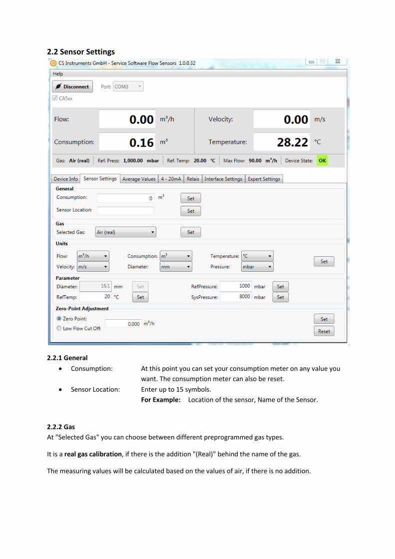
2.2 Sensor Settings
2.2.1 General
Consumption: At this point you can set your consumption meter on any value you
want. The consumption meter can also be reset.
Sensor Location: Enter up to 15 symbols.
For Example: Location of the sensor, Name of the Sensor.
2.2.2 Gas
At "Selected Gas" you can choose between different preprogrammed gas types.
It is a real gas calibration, if there is the addition "(Real)" behind the name of the gas.
The measuring values will be calculated based on the values of air, if there is no addition.

2.2.3 Units
For different measuring values you can choose different units (temperature, flow,...)
The units kW and kWh are only adjustable for the measuring values "Flow" and "Consumption", and
only for flammable gases.
2.2.4 Parameter
At the point "Parameter" you can change reference temperature and reference pressure . It is also
possible to enter your system pressure.
In case you have an immersion sensor it is possible to enter your pipe diameter at "Diameter".
The diameter don't have to be entered if you have a sensor with integrated measuring section.
2.2.5 Zero Point Adjustment
It is possible to enter a value that will used either for zero point calibration or low flow cut off.
Your entered value will be use as zero point, if you choose "Zero Point". The sensor will start
counting at this point. This adjustment is helpful if there is no flow in the pipe, but the sensor
shows some.
For example: Although there is 0,00 m3/h flow in the pipe the flow meter shows 0,08 m3/h.
Now you can raise up your zero point to 0,08 m3/h, the flow meter will show now 0,00 m3/h.
Your entered value will be use as cut off value, if you choose "Low Flow Cut Off". All
measuring values below this value won't be shown at the display of the VA5xx. The values
below your entered value also won't be calculated to the consumption meter. Even the 4 - 20
mA output will set to zero (4 mA) and there won't be impulses.
For Example: The flow meter shows about 8 m3/h. The customer set the low flow cut off at 10 m3/h.
The display and the impulse outlet now shows zero also the 4-20 mA outlet shows zero (4 mA).
0,00
10,00
20,00
30,00
40,00
50,00
60,00
70,00
9:07 9:14 9:21 9:28 9:36 9:43 9:50 9:57 10:04
Flo
w[m
3 /h
]
Uhrzeit
Low Flow Cut Off
With Low Flow Cut Off Without Low Flow Cut Off
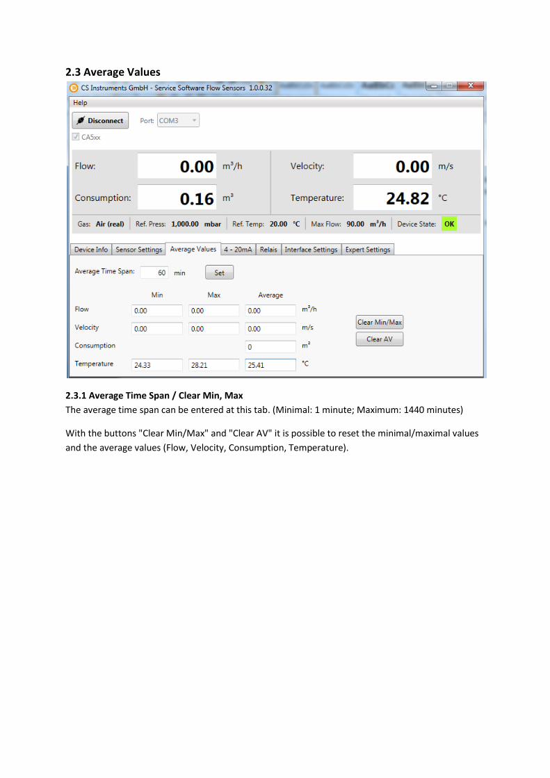
2.3 Average Values
2.3.1 Average Time Span / Clear Min, Max
The average time span can be entered at this tab. (Minimal: 1 minute; Maximum: 1440 minutes)
With the buttons "Clear Min/Max" and "Clear AV" it is possible to reset the minimal/maximal values
and the average values (Flow, Velocity, Consumption, Temperature).

2.4 4 - 20 mA
The VA5xx sensor has one (optional 2) 4 - 20 mA analog output(s). The outputs are individual
adjustable.
2.4.1 4 - 20 mA analog outputs settings
You can enter your desired measuring outputs at "Value". Please enter also the correct units for your
needs at "Unit".
Your upper limit value will be the measuring limit of the value that was set at "Value", if you choose
"Autoscale".
Please insert your specific limits at "Scale 4mA/Scale 20mA" if you want to scale manually.
You can also enter adjustments for "Channel 2", if the sensor is equipped with 2 channels.
It is possible to set different scenarios in case of an error at "Error Behaviour".
Stay at NAMUR limits: Depending on the the measuring value the output will be set 3,8 mA
or 20,5 mA.
Error = 22 mA: The output current will be set to 22 mA.
Error = 2 mA: The output current will be set to 2 mA.

2.5 Relais
The galvanic isolated output can set as puls- or alarm output.
2.5.1 Pulse settings
Please select "Pulse" with the button "Mode". You can now specify the desired settings for the pulse
output. Choose a unit for your pulse output at "Unit". You can change the pulse-value at "Value" and
the polarity at "Polarity" (pos. 0-->1; neg. 1-->0)
2.5.2 Alarm settings
Please select "Alarm" with the button "Mode". Select now your desired unit for the alarm. Specify
the alarm value. With "Direction" you can choose if you want to trigger the alarm whether by passing
the entered value or by falling below this value. You can also enter a value for the hysteresis at
"Hyst.".
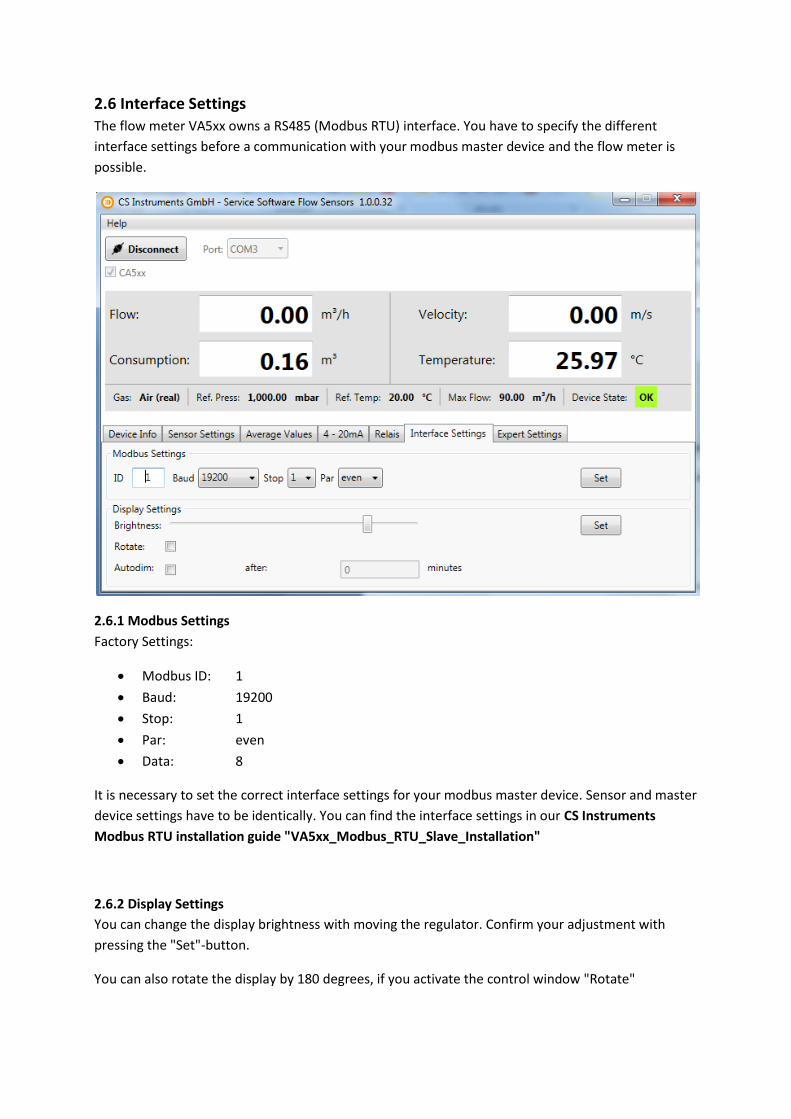
2.6 Interface Settings
The flow meter VA5xx owns a RS485 (Modbus RTU) interface. You have to specify the different
interface settings before a communication with your modbus master device and the flow meter is
possible.
2.6.1 Modbus Settings
Factory Settings:
Modbus ID: 1
Baud: 19200
Stop: 1
Par: even
Data: 8
It is necessary to set the correct interface settings for your modbus master device. Sensor and master
device settings have to be identically. You can find the interface settings in our CS Instruments
Modbus RTU installation guide "VA5xx_Modbus_RTU_Slave_Installation"
2.6.2 Display Settings
You can change the display brightness with moving the regulator. Confirm your adjustment with
pressing the "Set"-button.
You can also rotate the display by 180 degrees, if you activate the control window "Rotate"

2.7 Expert Settings
2.7.1 Calibration settings / Factory settings
You can change the next calibration date at "General"
The different parameters for calibration can be changed at "Parameter"
Offset: The measuring value will be changed by the entered value
Factor: The measuring value will be multiplied by the entered value
Temp. Offset: Correction of temperature
Filter Time: It is possible to enter a filter time to change the attenuation (0-10000 [ms])
Heat Rating: Enter a calorific value for flammable gases (0°C; 1013,25 mbar)
To reset the sensor to factory settings please press "Factory Reset".