
Installation and maintenance · terminal of the AC generator, with 277 VAC rms at 50 Hz or 60 Hz....
16
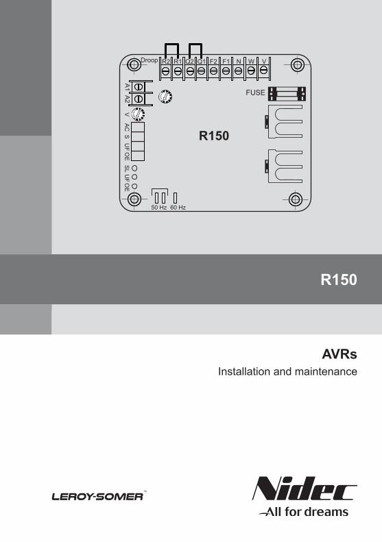
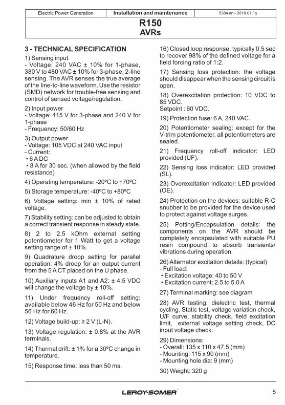
R2 Droop 50 Hz V AC S UF OE SL UF OE 60 Hz R1 A1 A2 Q2 Q1 F2 F1 N FUSE W V R150 R150 AVRs Installation and maintenance
Transcript of Installation and maintenance · terminal of the AC generator, with 277 VAC rms at 50 Hz or 60 Hz....
R2Droop
50 Hz
VA
CS
UF
OE
SL
UF
OE
60 Hz
R1
A1A2
Q2 Q1 F2 F1 N
FUSE
W V
R150
R150
AVRsInstallation and maintenance
2018.01 / g
2
Electric Power Generation Installation and maintenance
R150AVRs
5384 en -
SAFETY MEASURES
Before using your machine for the first time, it is important to read the whole of this installation and maintenance manual.
All necessary operations and interventions on this machine must be performed by a qualified technician.
Our technical support service will be pleased to provide any additional information you may require.
The various operations described in this manual are accompanied by recom-mendations or symbols to alert the user to potential risks of accidents. It is vital that you understand and take notice of the following warning symbols.
Warning symbol for an operation capable of damaging or destroying the machine or surrounding equipment.
Warning symbol for general danger to personnel.
Warning symbol for electrical danger to personnel.
All servicing or repair operations performed on the AVR should be undertaken by personnel trained in the commissioning, servicing and main-tenance of electrical and mechanical components.
When the generator is driven at a frequency below 28 Hz for more than 30 seconds with an analogue AVR, its AC power supply must be disconnected.
WARNINGThis AVR can be incorporated in a EC-marked machine.This manual is to be given to the end user.
© - We reserve the right to modify the characteristics of this product at any time in order to incorporate the latest technological developments. The information contained in this document may therefore be changed without notice.
This document may not be reproduced in any form without prior authorisation.All brands and models have been registered and patents applied for.
WARNING
This manual concerns the alternator AVR which you have just purchased.We wish to draw your attention to the contents of this maintenance manual.
2018.01 / g
3
Electric Power Generation Installation and maintenance
R150AVRs
5384 en -
CONTENTS
1 - GENERAL DESCRIPTION .................................................................................................4
2 - OPERATION OF THE AVR .................................................................................................4
3 - TECHNICAL SPECIFICATION ...........................................................................................5
4 - MAIN FUNCTION OF THE AVR .........................................................................................6
5 - AVR SETTINGS ..................................................................................................................7
5.1 - V-TRIM: V .....................................................................................................................75.2 - FRO: UF ......................................................................................................................75.3 - STAB: S .......................................................................................................................75.4 - EXC LIMIT: OE ............................................................................................................75.5 - QUADRATURE DROOP .............................................................................................75.6 - A1&A2 DC VOLTAGE INPUTS: AC .............................................................................7
6 - AVR CONTROLS ................................................................................................................7
7 - TROUBLESHOOTING CHART ..........................................................................................8
8 - MULTIMETER CHECKS ....................................................................................................9
9 - STATIC TEST PROCEDURE ...........................................................................................10
10 - DIMENSIONS ................................................................................................................. 11
11 - SPARE PARTS ...............................................................................................................12
11.1 - Designation ..............................................................................................................12
11.2 - Technical support service .........................................................................................12
Disposal and recycling instructions
2018.01 / g
4
Electric Power Generation Installation and maintenance
R150AVRs
5384 en -
1 - GENERAL DESCRIPTIONThe R150 automatic voltage regulator (AVR) is a compact, high-performance encapsulated unit. It incorporates the latest technology and efficient components to achieve a high degree of miniaturisation when applied to a 3-phase and 1-phase AC brushless generator, within its input and output limits. The unit offers excellent reliability.The AVR provides DC excitation to the exciter field of a brushless generator to keep the voltage within the approximate operating limits from NO-LOAD to FULL LOAD.The typical recovery time in the event of sudden loading is around 0.5 sec. to recover 98% of the rated voltage. Transient performance such as voltage dip and recovery time is mainly determined by the generator and exciter design parameters. Optimum AVR performance can be obtained by keeping full-load excitation to around 60 VDC.The generator uses a true average sensing circuit, dV/dt snubber and special filter circuits to manage NON-LINEAR loads such as battery chargers, DC motors, etc.Voltage regulation is only guaranteed for linear loads. Severely distorting NON-LINEAR loads can cause regulation problems.Each AVR is tested prior to dispatch as part of a quality plan, for standard voltage and frequency.The R150 AVR is provided with two accessory input terminals A1 and A2. Injecting ± 4.5 VDC into these terminals will change the generator voltage by ± 10%.The AVR allows a shunt power supply from the generator output voltage.A soft-start circuit is included which provides smooth control of the build-up of generator output voltage.A frequency roll-off circuit continuously monitors the generator underspeed protection by reducing the generator output voltage in proportion with the speed below a threshold.
The AVR has the facility for droop CT connection, which is required for equal KVAR load sharing during parallel operation.
2 - OPERATION OF THE AVRThe AVR is powered by the line-to-neutral terminal of the AC generator, with 277 VAC rms at 50 Hz or 60 Hz. The sensing voltage, which is the regulated voltage, is based on line-to-line (for 3-phase) and line-to-neutral (for 1-phase). The AVR forms an important part of the closed loop system comprising the generator field, generator armature and the AVR.The AVR first builds up the generator voltage from its residual levels. When the generator is loaded, the sensed voltage decreases and generates an error voltage, which is required in order for the closed loop system to work.The AVR contains a high gain amplifier, ramp and a pedestal circuit. Depending upon the value of the amplifier voltage (either high or low) the ramp intersects the amplified voltage at a point, which is either early or late in the half-cycle. At this intersection point a starting pulse is produced to trigger the power device.When the power device is triggered early in the half-cycle, more voltage is transmitted to the field and when triggered late in the half-cycle, less voltage is transmitted to the field.In order to reduce the generator voltage at low speed, a signal inversely proportionalto the speed is generated as an extra input. At higher speeds the voltage decreases at a faster rate than in proportion with the speed.The R150 AVR has two additional terminals A1 and A2. These inputs can be used to connect an external control signal from controllers such as APFC, Auto Synchronizer, etc.It is important that the DC power supply should be electrically isolated from the line terminals.
2018.01 / g
5
Electric Power Generation Installation and maintenance
R150AVRs
5384 en -
3 - TECHNICAL SPECIFICATION1) Sensing input- Voltage: 240 VAC ± 10% for 1-phase, 380 V to 480 VAC ± 10% for 3-phase, 2-line sensing. The AVR senses the true average of the line-to-line waveform. Use the resistor (SMD) network for trouble-free sensing and control of sensed voltage/regulation.2) Input power- Voltage: 415 V for 3-phase and 240 V for 1-phase- Frequency: 50/60 Hz3) Output power- Voltage: 105 VDC at 240 VAC input- Current: • 6 A DC • 8 A for 30 sec. (when allowed by the field resistance)4) Operating temperature: -20ºC to +70ºC5) Storage temperature: -40ºC to +80ºC6) Voltage setting: min ± 10% of rated voltage.7) Stability setting: can be adjusted to obtain a correct transient response in steady state.8) 2 to 2.5 kOhm external setting potentiometer for 1 Watt to get a voltage setting range of ± 10%.9) Quadrature droop setting for parallel operation: 4% droop for an output current from the 5 A CT placed on the U phase.
10) Auxiliary inputs A1 and A2: ± 4.5 VDC will change the voltage by ± 10%.
11) Under frequency roll-off setting: available below 46 Hz for 50 Hz and below 56 Hz for 60 Hz.
12) Voltage build-up: ≥ 2 V (L-N).
13) Voltage regulation: ± 0.8% at the AVR terminals.
14) Thermal drift: ± 1% for a 30ºC change in temperature.
15) Response time: less than 50 ms.
16) Closed loop response: typically 0.5 sec to recover 98% of the defined voltage for a field forcing ratio of 1:2.17) Sensing loss protection: the voltage should disappear when the sensing circuit is open.18) Overexcitation protection: 10 VDC to 85 VDC.Setpoint : 60 VDC.19) Protection fuse: 6 A, 240 VAC.20) Potentiometer sealing: except for the V-trim potentiometer, all potentiometers are sealed.21) Frequency roll-off indicator: LED provided (UF).22) Sensing loss indicator: LED provided (SL).23) Overexcitation indicator: LED provided (OE).
24) Protection on the devices: suitable R-C snubber to be provided for the device used to protect against voltage surges.
25) Potting/Encapsulation details: the components on the AVR should be completely encapsulated with suitable PU resin compound to absorb transients/ vibrations during operation.
26) Alternator excitation details: (typical)- Full load: • Excitation voltage: 40 to 50 V • Excitation current: 2.5 to 5.0 A
27) Terminal marking: see diagram
28) AVR testing: dielectric test, thermal cycling, Static test, voltage variation check, U/F curve, stability check, field excitation limit, external voltage setting check, DC input voltage check.
29) Dimensions:- Overall: 135 x 110 x 47.5 (mm)- Mounting: 115 x 90 (mm)- Mounting hole dia: 9 (mm)
30) Weight: 320 g
2018.01 / g
6
Electric Power Generation Installation and maintenance
R150AVRs
5384 en -
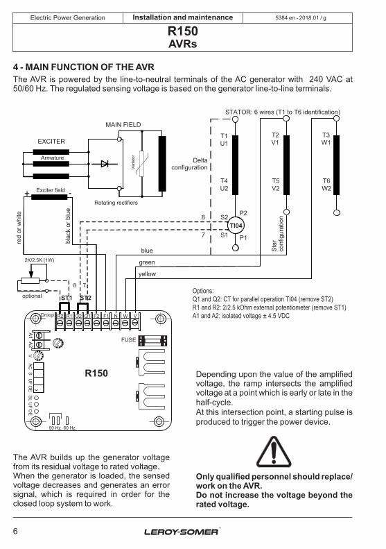
4 - MAIN FUNCTION OF THE AVRThe AVR is powered by the line-to-neutral terminals of the AC generator with 240 VAC at 50/60 Hz. The regulated sensing voltage is based on the generator line-to-line terminals.
The AVR builds up the generator voltage from its residual voltage to rated voltage. When the generator is loaded, the sensed voltage decreases and generates an error signal, which is required in order for the closed loop system to work.
Depending upon the value of the amplified voltage, the ramp intersects the amplified voltage at a point which is early or late in the half-cycle.At this intersection point, a starting pulse is produced to trigger the power device.
Only qualified personnel should replace/ work on the AVR.Do not increase the voltage beyond the rated voltage.
Options:Q1 and Q2: CT for parallel operation TI04 (remove ST2)R1 and R2: 2/2.5 kOhm external potentiometer (remove ST1)A1 and A2: isolated voltage ± 4.5 VDC
+ -+ -
2K/2.5K (1W)
78
R2Droop
50 Hz
VAC
SU
FO
ESL
UF
OE
60 Hz
R1
A1A2
Q2 Q1 F2 F1 N
FUSE
W V
ST1 ST2
T1U1
T4U2
T3W1
T6W2
P2S2
S1
8
7 P1
TI04
T2V1
T5V2
R150
EXCITER
MAIN FIELD
Armature
Exciter field
Varis
tor
Rotating rectifiers
optional
red
or w
hite
blac
k or
blu
e
STATOR: 6 wires (T1 to T6 identification)
yellow
green
blue Star
conf
igur
atio
n
Deltaconfiguration
2018.01 / g
7
Electric Power Generation Installation and maintenance
R150AVRs
5384 en -
5 - AVR SETTINGS5.1 - V-TRIM: VThis function is provided for setting the voltage up to ± 12% of rated voltage by means of a potentiometer. Turn the potentiometer clockwise to increase the voltage and vice versa, once the rated speed has been reached.It is also possible to connect an external potentiometer.
5.2 - UF - Under frequency knee point settingThis function is provided to protect the AC generator from sustained low speed operation through a potentiometer. The AVR will reduce the voltage in proportion with the speed below the defined value. The procedure for setting the UF potentiometer is as follows: First run the generator at full speed (50 Hz) and turn the UF potentiometer by a few turns clockwise, making sure that the voltage does not increase. Now turn the UF potentiometer slowly anticlockwise. At a particular point the red LED glows and the voltage will start to decrease. Stop turning the potentiometer at this point and turn the potentiometer clockwise by two turns after rated voltage is restored.The factory default setting is 46 Hz.For 60 Hz operation, the knee point position is set to 56 Hz.
5.3 - STAB: SThis function is provided to stop voltage hunting by means of a potentiometer. Turn clockwise to increase stability (to stop oscillation). Turning too far clockwise will
result in a sluggish response and possibly also oscillations.The factory default setting is slightly higher than critical damping (around halfway).
5.4 - EXC LIMIT: OEThis function is provided to protect the Exciter Field from overexciting by turning a potentiometer clockwise to increase the excitation limit. It is factory-set at 105 V. The red LED lights up when the ceiling has been reached for more than 10 s.
5.5 - QUADRATURE DROOPThis potentiometer is used to adjust the voltage droop to balance the reactive load in parallel operation. Follow the instructions for connecting the CT (current transformer) which is essential for this function, as per the AVR connection diagram.Turn the potentiometer clockwise to increase % droop and vice versa.
5.6 - A1&A2 DC VOLTAGE INPUTS: ACThese accessory terminals A1 and A2 are used to inject ± 1.0 to 4.5 VDC. The variation in terminal voltage will be ± 10% of the rated voltage.Warning: A “Vishay spectrol model 8” type screwdriver should be used to adjust the potentiometer.
6 - AVR CONTROLSNo. Control Function DirectionV VOLTS Sets the generator output voltage Turn clockwise to increase output voltage
UF UFRO Sets the Under frequency knee point Turn clockwise to reduce the knee pointS STAB Stops voltage hunting Turn clockwise to increase stability
OE OVER EXC Sets the overexcitation limit Turn clockwise to increase the limitDROOP DROOP Sets voltage droop Turn clockwise to increase the droop
AC ACC (DC i/p) Used for Auto synchronization Turn clockwise to increase the gain
2018.01 / g
8
Electric Power Generation Installation and maintenance
R150AVRs
5384 en -
7 - TROUBLESHOOTING CHART
Symptom Cause ActionNo voltagebuild-up
Fuse blown Check and replaceLow residual voltage across U and N terminals
If the generator’s residual voltage at rated speed is less than 2.5 VAC (L-N), disconnect the AVR and connect a 24 VDC battery, keeping F1 as positive and F2 as negative.Connecting a freewheel diode (BY 127) across the field with the diode cathode to F1 and the anode to F2 during field flashing will help restore the residual voltage.WARNING:Remove the diode (BY-127) after field flashing.The 24 V battery positive terminal must only be connected to F1 and the negative to F2.Swapping the connection will cause diode BY127 to explode instantly.
Incorrect wiring Check wiringRotating diodes and/or fuse failed
Check and replace
Voltmeter on the front defective
Check and correct
AVR defective(repeated fuse blowing)
Replace after performing a static test
Earthed exciter field Check and correctHigh voltagebuild-up
Loose or missing connection to AVR U terminal
Check and correct
AVR defective Perform a static test and replace if necessaryLow voltagebuild-up
Low prime mover speed Check and correctSensing loss in circuit Check and correctAVR defective Replace the AVR
Voltage oscillation Incorrect stability potentiometer sealing
Turn clockwise until hunting stops
Prime mover speed hunting Check and adjust the controllerLoad hunting, fluctuates rapidly
Check and correct
High percentage of non-linear loads
Check and reduce the non-linear load
High reactance in generator (during non-linear loading)
Consult the generator manufacturer
Incorrect regulation
The exciter field’s requirement is higher than 105 VDC
Wrong selection or very low P.F. load. Check and correct.
Prime mover speed drops too much when on load (kW load)
Adjust the controller and reduce the active load
2018.01 / g
9
Electric Power Generation Installation and maintenance
R150AVRs
5384 en -
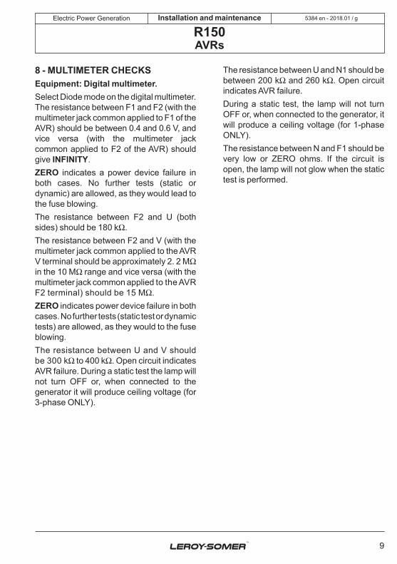
8 - MULTIMETER CHECKSEquipment: Digital multimeter.Select Diode mode on the digital multimeter. The resistance between F1 and F2 (with the multimeter jack common applied to F1 of the AVR) should be between 0.4 and 0.6 V, and vice versa (with the multimeter jack common applied to F2 of the AVR) should give INFINITY.ZERO indicates a power device failure in both cases. No further tests (static or dynamic) are allowed, as they would lead to the fuse blowing.The resistance between F2 and U (both sides) should be 180 kW.The resistance between F2 and V (with the multimeter jack common applied to the AVR V terminal should be approximately 2. 2 MW in the 10 MW range and vice versa (with the multimeter jack common applied to the AVR F2 terminal) should be 15 MW.ZERO indicates power device failure in both cases. No further tests (static test or dynamic tests) are allowed, as they would to the fuse blowing.The resistance between U and V should be 300 kW to 400 kW. Open circuit indicates AVR failure. During a static test the lamp will not turn OFF or, when connected to the generator it will produce ceiling voltage (for 3-phase ONLY).
The resistance between U and N1 should be between 200 kW and 260 kW. Open circuit indicates AVR failure.During a static test, the lamp will not turn OFF or, when connected to the generator, it will produce a ceiling voltage (for 1-phase ONLY).The resistance between N and F1 should be very low or ZERO ohms. If the circuit is open, the lamp will not glow when the static test is performed.

2018.01 / g
10
Electric Power Generation
F2 F1
F1 R
Y
B
N
F2
F3
N W V
Installation and maintenance
R150AVRs
5384 en -
9 - STATIC TEST PROCEDURE
For 3-phase circuit
This test should only be attempted after making sure that the AVR has passed all multimeter checks. Connect the AVR to the three-phase variable voltage source as shown in diagram for 3-phase installation in this manual.
1. Keep ‘V-TRIM’ in the minimum position.
2. Keep UF in the fully maximum position.
3. Increase the applied voltage. The lamp should glow increasingly brightly. At a voltage of around 360-380 V. The lamp should go out slowly. Increase the voltage again up to 415 V. The lamp should stay OFF.Decrease the voltage to below 360 V. The lamp should glow brightly again.
4. Turn the UF potentiometer anticlockwise; the lamp should go out slowly. Now turn the UF potentiometer clockwise. The lamp should glow brightly again.
5. It is difficult to prescribe a static test for checking the stability, as this is more easily detected during closed loop tests. However, a healthy AVR will behave as described below.
First keep the ‘STAB’ potentiometer in the fully anticlockwise position. Perform the static test as described in steps 1, 2 and 3. The lamp will go out fairly quickly at 360-380 V and come on again quickly when the voltage is reduced to below 360 V.Now keep the ‘STAB’ potentiometer fully clockwise, and perform the static test as in 1, 2, and 3. The lamp should go out much more slowly and come on again much more slowly. At the end of this test reset the potentiometer in the middle position.
If the AVR behaves as described above then the regulator is healthy.
AVR (3-PH)Model: R150
LAMP100 W230 V
VAC0-500 V
STATIC TEST CONNECTION DIAGRAM OF 3-PH AVR
415 V
, 3Ø,
50 H
z,W
ITH
NEUT
RAL
VARIAC8 A, 415 V
2018.01 / g
11
Electric Power Generation
135 mm
115 mm
110
mm
90 m
m
1010
R2Droop
50 Hz
VA
CS
UF
OE
SL
UF
OE
60 Hz
R1
A1A2
Q2 Q1 F2 F1 N
FUSE
W V
R150
Installation and maintenance
R150AVRs
5384 en -
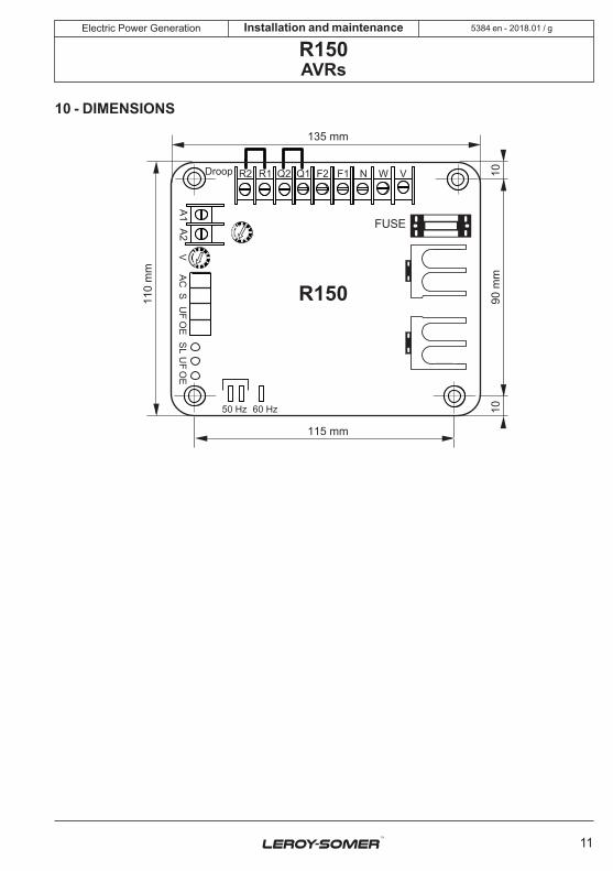
10 - DIMENSIONS

2018.01 / g
12
Electric Power Generation Installation and maintenance
R150AVRs
5384 en -
11 - SPARE PARTS11.1 - Designation
Description Type CodeAVR R150 5014127
11.2 - Technical support serviceOur technical support service will be pleased to provide any additional information you may require.
For all spare parts orders or technical support requests, send your request to [email protected] or your closest contact, whom you will find at www.lrsm.co/support indicating the type and the code number of the AVR.
To ensure that our products operate correctly and safely, we recommend the use of original manufacturer spare parts.
In the event of failure to comply with this advice, the manufacturer cannot be held responsible for any damage.
2018.01 / g
13
Electric Power Generation Installation and maintenance
R150AVRs
5384 en -
Disposal and recycling instructionsWe are committed limiting the environmental impact of our activity. We continuously monitor our production processes, material sourcing and products design to improve recyclability and minimise our environmental footprint.
These instructions are for information purposes only. It is the user’s responsibility to comply with local legislation regarding product disposal and recycling.
Waste & hazardous materials The following components and materials require special treatment and must be separated from the alternator before the recycling process:- electronic materials found in the terminal box, including the automatic voltage regulator (198), current transformers (176), interference suppression module (199) and other semi-conductors.- diode bridge (343) and surge suppressor (347), found on the alternator rotor.- major plastic components, such as the terminal box structure on some products. These components are usually marked with information concerning the type of plastic.
2018.01 / g
14
Electric Power Generation Installation and maintenance
R150AVRs
5384 en -
[email protected] www.lrsm.co/support
Design
Life Extension
Optimisation
Start-up
Operation
•Consulting & specification•Maintenance
contracts
•Reconditioning•System upgrade
•Monitoring•System audit
•Commissioning•Training
•Genuine spare parts•Repair services
Our worldwide service network of over 80 facilities is at your service.This local presence is our guarantee for fast and efficient repair, support and maintenance services.Trust your alternator maintenance and support to electric power generation experts. Our field personnel are 100% qualified and fully trained to operate in all environments and on all machine types.We have a deep understanding of alternator operation, providing the best value service to optimise your cost of ownership.
Where we can help:
Contact us:Americas: +1 (507) 625 4011Europe & Rest of the world: +33 238 609 908Asia Pacific: +65 6250 8488 China: +86 591 88373036India: +91 806 726 4867Middle East: +971 4 811 8483 Scan the code or go to:
Service & Support

- 2018.01 / g
www.leroy-somer.com/epg
5384 en
Linkedin.com/company/Leroy-SomerTwitter.com/Leroy_Somer_enFacebook.com/LeroySomer.Nidec.enYouTube.com/LeroySomerOfficiel


![High Voltage - Comar Condensatori · Network voltages Voltage systems ( belongs to IEC 60038 @50 Hz, belongs to IEC 60038 @60 Hz) Insulation level [kV] (Power freq. voltage withstand](https://static.fdocuments.in/doc/165x107/5b07063f7f8b9a56408c7527/high-voltage-comar-condensatori-voltages-voltage-systems-belongs-to-iec-60038.jpg)