Installation and Maintenance Manual Power Unit PEC · Installation and Maintenance Manual, Power...
34
Installation and Maintenance Manual Power Unit PEC EN326-6h 2005
Transcript of Installation and Maintenance Manual Power Unit PEC · Installation and Maintenance Manual, Power...

Installation and Maintenance Manual
Power Unit PEC EN326-6h 2005
2
Installation and Maintenance Manual, Power Unit PEC
PrefaceHägglunds Drives is one of the worlds leading manufacturers of large hydraulic Drive Systems. A leading position, made possible by unbeatable service spirit and of continuing development of both products and markets all over the world. Our drives are to be found in most industrial and marine segments, where there are extremely high demands for effi ciency and reliability. Our main offi ce and production plant is in Mellansel, Sweden and we have our own sales- and representation offi ces in some 40 different countries.
Our high quality Drive Systems, are based upon our unique hydraulic piston motors, developed through a wealth of experience accumulated over 30 years in marine and industrial areas.Today this ongoing development work has re-sulted in the powerful Power Unit, PEC. New, as well as established technical solutions, contribute to the creation of this product. The most desirable features and operating reliability have been designed in this Power Unit, PEC.
This manual provides necessary information for installation and maintenance of the Power Unit. In order to fi nd particular information, just search for the wanted section as listed in the table of contents. However, changes in the equipment may occur. We therefore reserve the right to introduce amendments in the manual as we deem necessary without notice or obligations.
Before starting the installation/maintenance, the manual must be read and understoud in all respects. All involved personnel shall be in agreement with the Safety precautions which is described in section 1.1.
This Installation and Maintenance Manual is valid for Power Units manufactured after 97-07-01. For older Power Units please contact your nearest Hägglunds Drives representative.
Orig
inal
EN
326-
5a, 1
999
Preface

3
Installation and Maintenance Manual, Power Unit PEC
Contents1. GENERAL ........................................................................................................................................................... 4
1.1 Safety precautions ............................................................................................................................................. 4
1.2 Operating principle .............................................................................................................................................. 6
2. TECHNICAL DATA ............................................................................................................................................. 7
2.1 Choice of hydraulic fl uid ..................................................................................................................................... 7
2.2 Requirements for hydraulic fl uid cleanliness ...................................................................................................... 8
2.3 Cooling Water ..................................................................................................................................................... 8
2.4 Power Unit monitoring ......................................................................................................................................... 9
2.5 Miscellaneous components .............................................................................................................................. 10
3. HANDLING OF THE PACKED POWER UNIT ................................................................................................. 11
3.1 Storage of the packed Power Unit .................................................................................................................... 11
3.2 Lifting the packed Power Unit ........................................................................................................................... 11
4. INSTALLATION ................................................................................................................................................ 12
4.1 Installation directions ......................................................................................................................................... 12
4.2 Lifting methods and weights .............................................................................................................................. 13
4.3 Positioning the power unit ................................................................................................................................. 14
4.4 Mounting of the cabinet feet .............................................................................................................................. 14
4.5 Mounting of the electric motor .......................................................................................................................... 15
4.6 Mounting of the top cover ................................................................................................................................. 16
4.7 Mounting of the air-oil cooler ............................................................................................................................ 16
4.8 Hydraulic connections ....................................................................................................................................... 17
4.9 Electric connections .......................................................................................................................................... 18
4.10 Water connections ............................................................................................................................................. 19
4.11 Pipework .......................................................................................................................................................... 19
4.12 Flushing before start up .................................................................................................................................... 21
4.13 Commissioning .................................................................................................................................................. 21
4.13.1 Before commissioning ................................................................................................................................... 21
4.13.2 Filling up the system with hydraulic fl uid. ...................................................................................................... 21
4.13.3 Initial start up procedure ............................................................................................................................... 23
4.14 Pump settings and adjustments ..................................................................................................................... 25
4.14.1 Hägglunds Drives pump ............................................................................................................................... 25
4.14.2 Denison pump ............................................................................................................................................... 26
4.14.3 Sauer pump .................................................................................................................................................. 27
5. PREVENTIVE MAINTENANCE ........................................................................................................................ 28
5.1 Maintenance log ............................................................................................................................................... 28
5.2 Maintenance chart ............................................................................................................................................ 28
5.3 Filter change ..................................................................................................................................................... 29
5.4 Inspection of hydraulic fl uid ............................................................................................................................... 29
5.5 Lubrication of electrical motor ........................................................................................................................... 30
5.6 Air fi lter change ................................................................................................................................................. 30
5.7 Cleaning of Water-Oil Cooler ........................................................................................................................... 31
5.8 Cleaning of Air-Oil Cooler ................................................................................................................................ 31
5.9 Power Unit out of service ................................................................................................................................. 31
6. CORRECTIVE MAINTENANCE ....................................................................................................................... 32
6.1 Common ........................................................................................................................................................... 32
6.2 Change of El-motor/Pump unit ......................................................................................................................... 32
6.3 Fault fi nding ...................................................................................................................................................... 33
7. SCRAPPING .................................................................................................................................................... 34
8. DECLARATION OF CONFORMITY ................................................................................................................. 34
Contents
4
Installation and Maintenance Manual, Power Unit PEC
1. GENERAL1.1 Safety precautionsIt is of high importance that the Safety precautions are always followed, if you are unsure about something, please don´t hesitate to contact your nearest HD-offi ce for advice.
Special Power Units
Standard Power Units are not allowed to be used beside an ambient temperature of 0°C to 50°C, or in areas with potentially explosive atmospheres.
For lower ambient temperature than 0° C and in areas with potentially explosive atmospheres, special Power Units have to be used.
Power Units intended for use in ambient temperature below 0° C, will be fi tted with special optio-nal equipment for preheating the hydraulic system before starting up.
Power Units intended for use in areas with potentially explosive atmospheres will be fi tted with suitable components for use in such areas and manufactured in accordance with valid rules and standards complying with ATEX-directives or corresponding. Power Units intended for use in such areas will be marked in a way that shows in which type of areas it can be used.
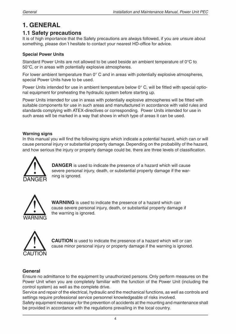
Warning signs In this manual you will fi nd the following signs which indicate a potential hazard, which can or will cause personal injury or substantial property damage. Depending on the probability of the hazard, and how serious the injury or property damage could be, there are three levels of classifi cation.
GeneralEnsure no admittance to the equipment by unauthorized persons. Only perform measures on the Power Unit when you are completely familiar with the function of the Power Unit (including the control system) as well as the complete drive.Service and repair of the electrical, hydraulic and the mechanical functions, as well as controls and settings require professional service personnel knowledgeable of risks involved.Safety equipment necessary for the prevention of accidents at the mounting and maintenance shall be provided in accordance with the regulations prevailing in the local country.
DANGER is used to indicate the presence of a hazard which will cause severe personal injury, death, or substantial property damage if the war-ning is ignored.
WARNING is used to indicate the presence of a hazard which can cause severe personal injury, death, or substantial property damage if the warning is ignored.
CAUTION is used to indicate the presence of a hazard which will or can cause minor personal injury or property damage if the warning is ignored.
General

5
Installation and Maintenance Manual, Power Unit PEC
Before any measures- Use the Order code and other attached technical documentation to identify the features of your
unique Power Unit and system.- Read the attached technical documentation (this manual included) and make yourself familiar
with the Power Unit (control system included) as well as the complete drive.- Use safety equipment like helmet, protective goggles, safety shoes and hearing protection. Always ensure that no energy is accumulated before any measures.- Ensure that all electric power is cut and locked out.- Ensure that there is no enclosed pressure in the hydraulic system (housing load). - Ensure that no pressure will enter the hydraulic system in the power unit via the hydraulic motor
eg loads on the shaft or winch drum.- If the hydraulic system is used for lift devices, these should be secured, or in the rest position
(hanging load).- Ensure that all accumulators are discharged.
Electricity supplySafety equipment necessary for the prevention of accidents shall be provided in accordance with the regulations prevailing in the local country.All electrical supply levels shall be within the limits that the equipment is constructed for, see tech-nical documentation and maximum rating plates.
Mounting Carefully follow the instructions and be aware of the high weights and forces during lifting. Incorrect mounting and setting of electrical, hydraulic and the mechanical functions, as well as controls can cause personal injury or property damage.
Before starting upBefore starting up new, rebuild or just worked on, applications. All accessories and safety arrang-ement functions, should be controlled/tested.
Maintenance and serviceNotice the special maintenance intervals for your specifi c Power Unit or the maximum intervals on the maintenance chart (section 5.2) and keep a maintenance log. Regular and correct maintenance and service are necessary conditions for reliable and safe operation.Use only spare parts recommended and supplied by the Hägglunds Drives organization.
Hydraulic fl uidNotice that most hydraulic fl uids can cause personal injury and major damage on the environment, check the caution sign on the container or consult the supplier. Used hydraulic fl uid can contain noxious contaminations. We recommend using the sevice of professional oil company for supply and disposal of fl uids used. Never dump hydraulic fl uid into drainages or water courses.
BellhousingNote that there are rotating parts inside the bellhousing during operation. Be careful during inspec-tion through the inspection hole. Put back the plug.
Hot surfacesHot surfaces locally temperatures above 70°C (158°F) can be experienced.
Emergency situationsEmergency shutdown: It must be possible to cut the electric power at emergency situations. Fire-extinguisher: Use only fi re-extinguisher adapted for use both to oil products and electric equipment.
General

6
Installation and Maintenance Manual, Power Unit PEC
1.2 Operating principleMain components
1. Hydraulic pump2. Electric motor3. Control system, Spider (option)4. Water-oil cooler (option)5. Oil fi lter (drain)6. Oil fi lter (return)7. Air breather fi lter8. Water valve (option)9. Junction box10. Suction line indicator11. Level switch12. Temperature switch13. Oil heater (option)14. Accumulator (option)15. Level indicator16. Drain cock oil tank17. Drain plug oil pan18. Charge pressure gauge19. Working pressure gauge
FunctionThe intention with the Power Unit is to provide the hydraulic motor(s) (or other hydraulic systems) with the required fl ow of oil and pressure at the right time. All included parts are assembled in one (or more) compact cabinet(s). The Power Unit has one or more pumps driven by one or more electric motors. The main pump is an axial piston pump with variable displacement for closed loop systems. The electric motor is totally enclosed. Three different control systems are available.
Control systems availableSpider: A small, compact and configurable control system. It can health monitor the Power Unit and can control one or two pumps with three pre-programmed functions:
- Basic, for most of our drives can be confi gured for speed feedback control and power limitation. - Shredder, for shredder applications. - Syncro, for friction and synchronized drives.
The Power Unit is a very fl exible product with a wide op-tion range. This makes it possible to select a standard Power Unit to fulfi ll the features needed in many different applications.This installation and maintenance manual is intended to cover all standard options.It may not cover all details on special Power Units that differs from the standard Power Unit consept.
It is of great importance to check the other attached technical docu-mentation to identify the features of your unique Power Unit.
Operating principle
DCA: Based on electronic control cards, with different cards for different pump types and functions.
MCA: For special control functions, normally based on PLC and control cards.
It is also possible to control the Power Unit from external control systems provided by the customer.
Note: Changes from the picture and main components tables above may occur.
7
Installation and Maintenance Manual, Power Unit PEC
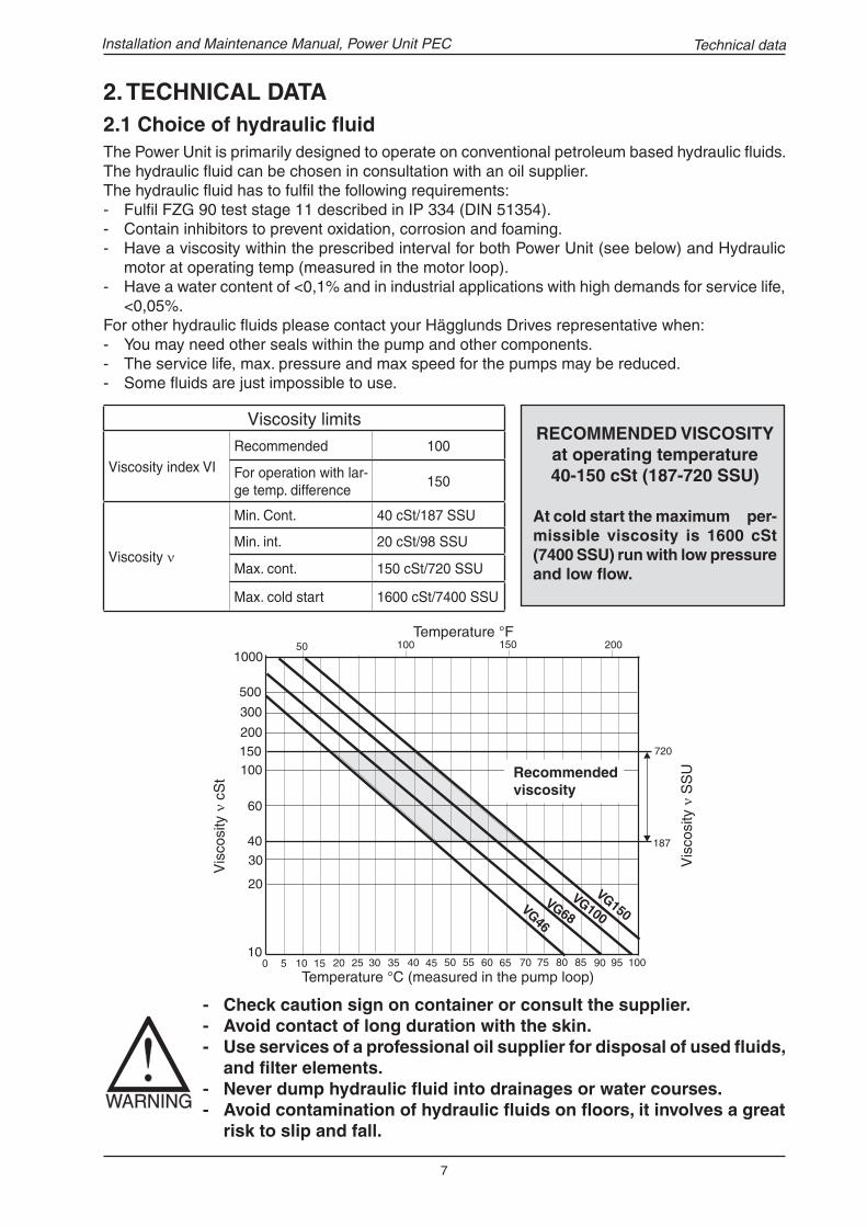
2.1 Choice of hydraulic fl uidThe Power Unit is primarily designed to operate on conventional petroleum based hydraulic fl uids. The hydraulic fl uid can be chosen in consultation with an oil supplier.The hydraulic fl uid has to fulfi l the following requirements: - Fulfi l FZG 90 test stage 11 described in IP 334 (DIN 51354).- Contain inhibitors to prevent oxidation, corrosion and foaming.- Have a viscosity within the prescribed interval for both Power Unit (see below) and Hydraulic
motor at operating temp (measured in the motor loop).- Have a water content of <0,1% and in industrial applications with high demands for service life,
<0,05%.For other hydraulic fl uids please contact your Hägglunds Drives representative when:- You may need other seals within the pump and other components.- The service life, max. pressure and max speed for the pumps may be reduced.- Some fl uids are just impossible to use.
RECOMMENDED VISCOSITY at operating temperature 40-150 cSt (187-720 SSU)
At cold start the maximum per-missible viscosity is 1600 cSt (7400 SSU) run with low pressure and low fl ow.
- Check caution sign on container or consult the supplier.- Avoid contact of long duration with the skin.- Use services of a professional oil supplier for disposal of used fl uids,
and fi lter elements. - Never dump hydraulic fl uid into drainages or water courses.- Avoid contamination of hydraulic fl uids on fl oors, it involves a great
risk to slip and fall.
Vis
cosi
ty ν
cS
t Recommended viscosity
Temperature °C (measured in the pump loop)
Technical data
2. TECHNICAL DATA
Viscosity limits
Viscosity index VIRecommended 100
For operation with lar-ge temp. difference
150
Viscosity ν
Min. Cont. 40 cSt/187 SSU
Min. int. 20 cSt/98 SSU
Max. cont. 150 cSt/720 SSU
Max. cold start 1600 cSt/7400 SSU
Temperature °F
Vis
cosi
ty ν
SS
U

8
Installation and Maintenance Manual, Power Unit PEC
2.2 Requirements for hydraulic fl uid cleanlinessThe Power Units are equiped with fi lters on the drain- & return- line(s). In order to obtain stated service life it is important to follow recommendations concerning cleanliness levels and maintenance.
Cleanliness level recommendations- The system must be fl ushed before start up, see section “ Flushing before start up “.- When fi lling the tank with hydraulic fl uid it is important to fi ll through the special oil fi ller connec-
tion, see section ” Filling up the system with hydraulic fl uid “- The solid contamination level in the system should not exceed ISO/DIS 4406, 19/16/13 (NAS
1638, class 7).- The water content shall be < 0,1% and in industrial applications with high demands for service
life, <0,05%.- Always use fi lter elements recommended and supplied by the Hägglunds Drives organization.- The hydraulic fl uid should be analyzed according to the special maintenance intervals for your
specifi c Power Unit or the maximum intervals on the maintenance chart (section "Maintenance chart"). Be particularly vigilant when removing equipment for repairs or maintenance, dirt must not be allowed to enter the system, clean prior to opening.
2.3 Cooling water
The cooling system is primarily designed to operate on clean fresh water. When there are particles in the water, larger than 0,5 mm (0,02 in), a water fi lter has to be used.It is important to : - Maintain the water fi lter (if any) in a correct way, this is to get the required fl ow of water through
the water oil cooler. - Have the required fl ow, pressure and temperature of the cooling water (see attached technical
documentation).- Check the temperature in the hydraulic system, according to the special maintenance intervals
for your specifi c Power Unit or the maximum intervals on the maintenance chart.- Clean the cooling system if the temperature in the hydraulic system is above the specifi ed limits
on account of too low cooling capacity.- Clean and empty the cooling system (water side) before periods of rest (especially if the cooling
water is not totally clean).
If cooling capacity is too low, the service life of Hydraulic motor, the main components in Power Unit and the hydraulic fl uid will be reduced.
Technical data
Do not re-use hydraulic fl uid which has leaked out.
9
Installation and Maintenance Manual, Power Unit PEC
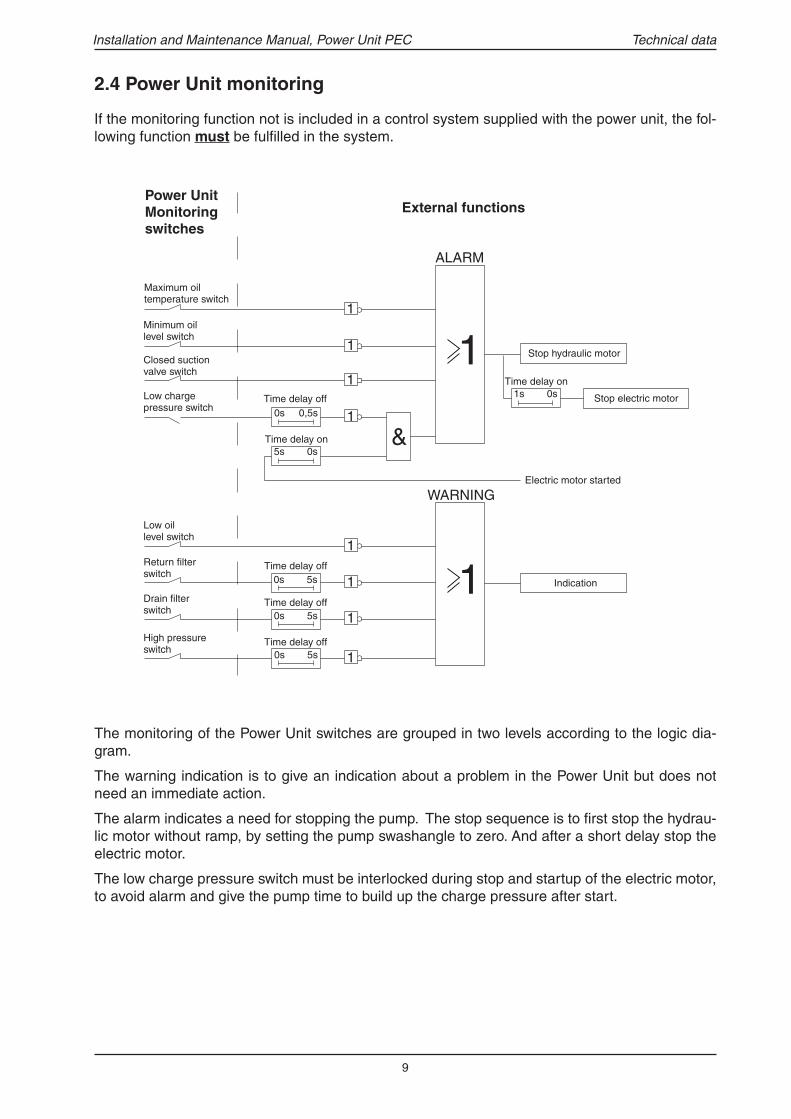
2.4 Power Unit monitoring
Technical data
If the monitoring function not is included in a control system supplied with the power unit, the fol-lowing function must be fulfi lled in the system.
The monitoring of the Power Unit switches are grouped in two levels according to the logic dia-gram.
The warning indication is to give an indication about a problem in the Power Unit but does not need an immediate action.
The alarm indicates a need for stopping the pump. The stop sequence is to fi rst stop the hydrau-lic motor without ramp, by setting the pump swashangle to zero. And after a short delay stop the electric motor.
The low charge pressure switch must be interlocked during stop and startup of the electric motor, to avoid alarm and give the pump time to build up the charge pressure after start.

10
Installation and Maintenance Manual, Power Unit PEC
Levels on level switch
Level ActionLevel from top of tank mm (in)
Low Warning 200 (7,87)
Min Alarm, stop Power Unit 256 (10,43
Technical data
2.5 Miscellaneous componentsLocation of internal scales on the Temperature Switch
Level switch
Inspection cover on tankReplace the gasket when opening the inspec-tion cover.
Isolation valve on pressure gaugesRelease isolation valves for pressure gauges when they are not used. If gauges are press-urized continuously they may be damaged.
Accumulator precharge pressure At the top of the accumulator there is a gas valve connected to the bladder. Use the char-ging set to check the precharge pressure.
Manual override on water valveIt is possible to open the water valve manually with a screw (counter clockwise), located ac-cording to picture beside.
NOTICE!The accumulator must be charged with dry nitrogen from a bottle equipped with a pressure reducing valve.
Screw
Standard location of internal scales
Operation Level
Number of internal scale
2switches
5switches
6switches
Stop Power Unit Max: > Note 1 1 2 3
Pilot light on Warning: > Note 1 - 1 2
Cooler on Start cooling: > 40°C (104°F) 2 3 5
Oilheater on Start heating: < 15°C (59°F) - - 4
Stop Power Unit Min: < 10°C (50°F) - - 1
Start of warm fl ushing
Min: < 30°C (86°F) 6
6 switches version ( 3 and 5 switches version available also)
Note 1: Temperature setting according to current documentation for PEC unit. See documentation.
Temperature Sensor Device(Alternative temperature measuring device)
Temperature levels to be set in the Spider II or other control system. Setting levels accor-ding to Temperature Switch and PEC docu-menation.

11
Installation and Maintenance Manual, Power Unit PEC
3.2 Lifting the packed Power Unit
The packed Power Unit is among other things bran-ded with centre of gravity and weight. Normally the Power Unit package is designed for forklift truck handling.
- Centre of gravity is high, see label on the goods.- Avoid rapid acceleration, deceleration and turns while
moving the goods. - Position the forks according to the instructions be-
low.
Lifting with fork lift- The absolute minimum requi red fork length is 1300 mm (51,2 in).- The minimum distance between the forks is 800 mm (31,5 in) for a 2-door Power Unit and 1100 mm (43,3 in) for a 3-door Power Unit.- Position forks about the centre of gravity.
Parts that are delivered separatelyThe package is always branded with the weight.- Packages on loading stools are only designed for forklift truck handling .- Some other packages may be lifted with a lifting crane, always check the lable on the
package.
- Do not stand under hanging load.- Use only lifting equipment adapted to
the weight on the label of the package.
Centre of gravity label
3. HANDLING OF THE PACKED POWER UNIT3.1 Storage of the packed Power UnitAt delivery, the hydraulic components are protected internally by an oil fi lm (containing rust pre-venting additives). This provides suffi cient protection for indoor storage in air conditioned premises for about 12 months. The Power Unit and belonging parts should be stored indoors, in dry, vibration free and dust free conditions. It should not be stored for more than three months in non-air conditioned premises. (the text above includes parts belonging to the Power Unit delivered separately).
The power unit must be placed where not exposed to strong sunlight or severe cooling to avoid condensation.
If storage time exceed limits, the Power Unit must be operated so that the hydraulic system is lubricated with new fl uid. (see section "Power Unit out of service")
Technical data
12
Installation and Maintenance Manual, Power Unit PEC
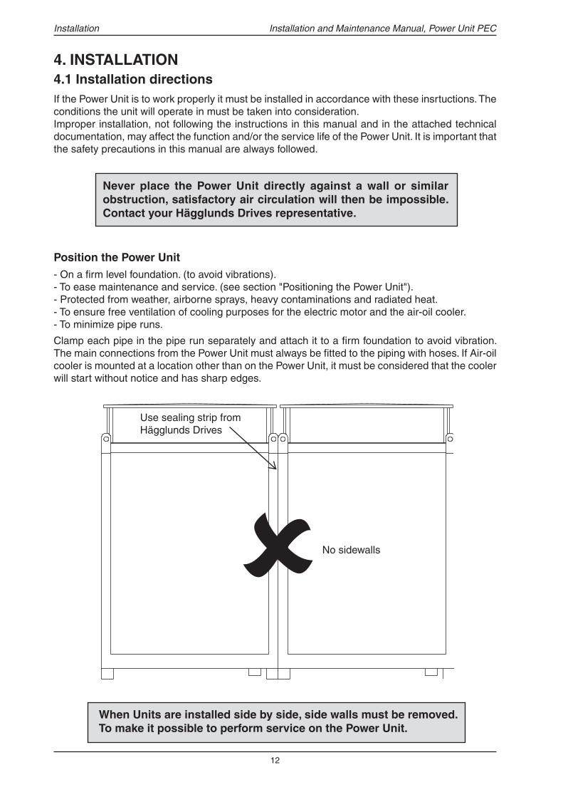
4. INSTALLATION4.1 Installation directionsIf the Power Unit is to work properly it must be installed in accordance with these insrtuctions. The conditions the unit will operate in must be taken into consideration. Improper installation, not following the instructions in this manual and in the attached technical documentation, may affect the function and/or the service life of the Power Unit. It is important that the safety precautions in this manual are always followed.
- On a fi rm level foundation. (to avoid vibrations).- To ease maintenance and service. (see section "Positioning the Power Unit"). - Protected from weather, airborne sprays, heavy contaminations and radiated heat. - To ensure free ventilation of cooling purposes for the electric motor and the air-oil cooler.- To minimize pipe runs.
Clamp each pipe in the pipe run separately and attach it to a fi rm foundation to avoid vibration. The main connections from the Power Unit must always be fi tted to the piping with hoses. If Air-oil cooler is mounted at a location other than on the Power Unit, it must be considered that the cooler will start without notice and has sharp edges.
When Units are installed side by side, side walls must be removed. To make it possible to perform service on the Power Unit.
Use sealing strip from Hägglunds Drives
Installation
Never place the Power Unit directly against a wall or similar obstruction, satisfactory air circulation will then be impossible. Contact your Hägglunds Drives representative.
Position the Power Unit
�No sidewalls

13
Installation and Maintenance Manual, Power Unit PEC
Electric motor ABB
Power kW Weight* kg (lb)
18,522303745557590110132160200250315355400500
138 (304)155 (341)195 (429)235 (517)250 (550)300 (660)450 (990)490 (1078)675 (1485)730 (1606)850 (1870)970 (2134)1350 (2970)1550 (3410)1550 (3410)1900 (4180)2400 (5280)
Pumps
Hägglunds Drives
Weight kg (lb)
SP40SP71SP125SP180SP250SP355SP500SP750
77 (170)94 (207)135 (298)150 (330)250 (550)270 (594)385 (847)540 (1188)
Dension Weight kg (lb)
P6P7P11P14P24P30
152 (335)152 (335)220 (484)220 (484)342 (753)357 (786)
Sauer Weight kg (lb)
90R 4290R 5590R 7590R 10090R 13090R 180
39 (86)47 (104)56 (123)77 (170)97 (213)145 (319)
Air-Oil Cooler
Size Weight kg (lb)
TBI 23-4TBI 33-4TBI 56-6TBI 76-6TBI 110-6
36 (79)52 (115)75 (165)140 (308)170 (374)
4.2 Lifting methods and weights
If fi tted, always use all four lifting points when lifting the Power Unit.
- Do not stand under hanging load.- Use only lifting equipment adapted to the weight of
the Power Unit (check rating plate inside the cabinet).- Centre of gravity is high, see label on cabinet.- Do not lift the Power Unit with Hydraulic fl uid in the
tank, or with the front bar disassembled.
Lifting with fork lift- The absolute minimum requi red fork length is 1300 mm
(51,2 in).- The minimum distance between the forks is 800 mm
(31,5 in) for a 2-door Power Unit and 1100 mm (43,3 in) for a 3-door Power Unit.
- Position forks about the centre of gravity.
Lifting with ropes/chains
Installation
*This is the weight for a stand-ard el-motor, more accurate weight for a specifi c motor can be found on the rating plate.
The total weight of the Power Unit, is stamped on the rating plate located on the Junction box door inside the cabinet.
Lift the Power Unit with no top cover on, max. lifting angle 90°.
Max 90°
14
Installation and Maintenance Manual, Power Unit PEC
Cabinet size
Power Unit
Adj. height
Amm (in)
Adj. screw Width
across fl ats mm (in)
1 PEC 102/20225-55
(0,98-2,17)18
(0,71)2 PEC 103/203
3 PEC 302/402/602
4 PEC 303/403/603
30-60 (1,18-2,36)
24(0,94)
5 PEC 803/1003
6 PEC 702
7 PEC 1203
Cabinet size
Power UnitMinimun Space mm (in)
A B C D E
1 PEC 102/202
700 (27,56)
1200 (47,24)
900 (35,43)
200 (7,87)
700 (27,56)
2 PEC 103/203
3 PEC 302/402/602 1300 (51,18)4 PEC 303/403/603
5 PEC 803/10031500
(59,06)
6 PEC 702 1800(70,87/7 PEC 1203
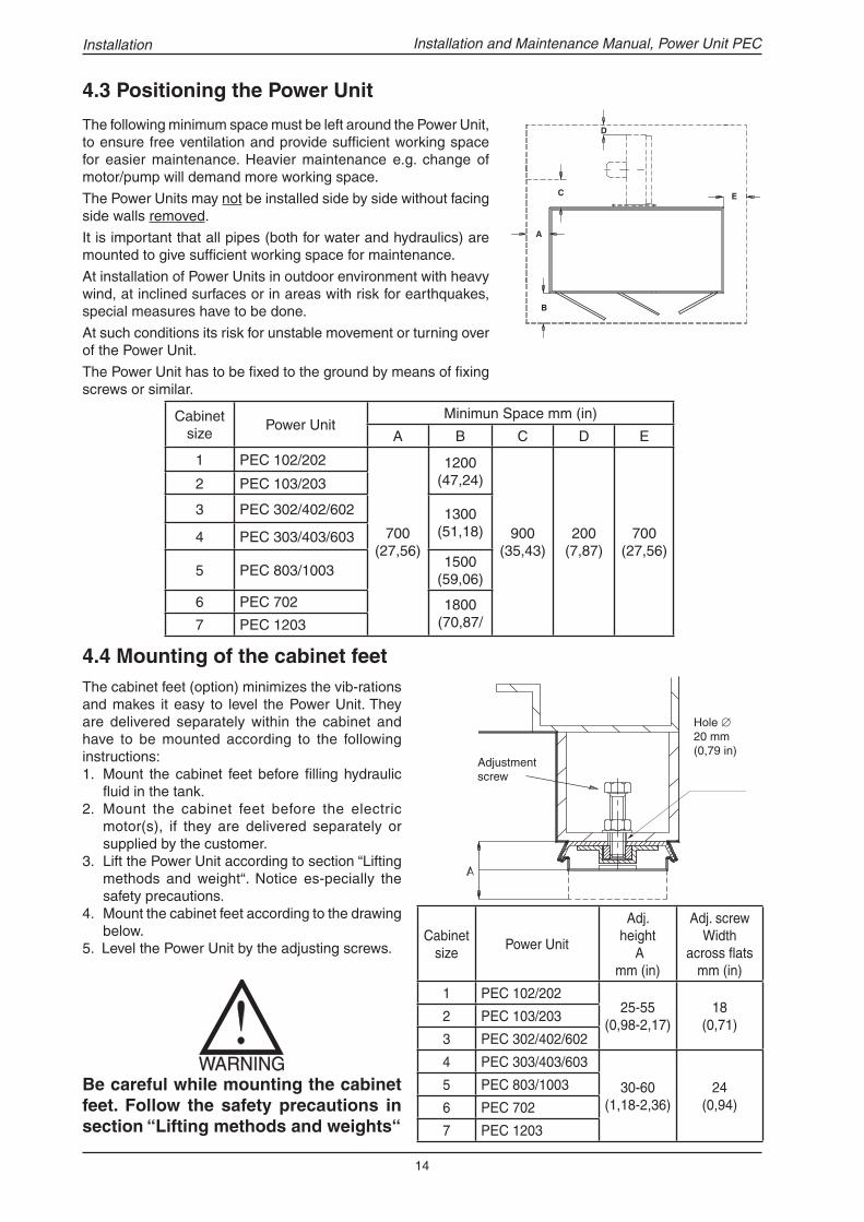
The cabinet feet (option) minimizes the vib-rations and makes it easy to level the Power Unit. They are delivered separately within the cabinet and have to be mounted according to the following instructions:1. Mount the cabinet feet before fi lling hydraulic
fl uid in the tank.2. Mount the cabinet feet before the electric
motor(s), if they are delivered separately or supplied by the customer.
3. Lift the Power Unit according to section “Lifting methods and weight“. Notice es-pecially the safety precautions.
4. Mount the cabinet feet according to the drawing below.
5. Level the Power Unit by the adjusting screws.
Be careful while mounting the cabinet feet. Follow the safety precautions in section “Lifting methods and weights“
4.3 Positioning the Power Unit
The following minimum space must be left around the Power Unit, to ensure free ventilation and provide suffi cient working space for easier maintenance. Heavier maintenance e.g. change of motor/pump will demand more working space.
The Power Units may not be installed side by side without facing side walls removed.
It is important that all pipes (both for water and hydraulics) are mounted to give suffi cient working space for maintenance.
At installation of Power Units in outdoor environment with heavy wind, at inclined surfaces or in areas with risk for earthquakes, special measures have to be done.
At such conditions its risk for unstable movement or turning over of the Power Unit.
The Power Unit has to be fi xed to the ground by means of fi xing screws or similar.
Installation
Hole ∅ 20 mm (0,79 in)
Adjustment screw
4.4 Mounting of the cabinet feet

15
Installation and Maintenance Manual, Power Unit PEC
Coupling TypeAxial clearance S
mm (in)
R 38
3 (0,12)A 42/55
A 42, R 42
A 48/60, R 48 3,5 (0,14)
A 55/70, R 55 4 (0,16)
R 65 4,5 (0,18)
A 75/90, R 755 (0,20)
A 75
A 90
R 90 5,5 (0,22)
A 90/100
A 100/110, R 100 6 (0,24)
R 110 6,5 (0,26
4.5 Mounting of electric motor
1. Remove the roof from the Power UnitUntighten the screws that keep the roof on the top cover. Mount lifting eye bolts in their holes on the corners of the roof, and lift the roof away. If range of lift is unsuffi cient, front panel and front beam of the Power Unit can be removed.
2. Remove the sound baffl eLift away the sound baffl e and put it on a place where it may not be damaged. When putting back, the insulation material must be turned upwards.
3. Unpack the electric motor(s)Unpack the electric motor. Check the electric motor for exter-nal damage and that all rating plate data are the same as in the attached technical documentation.
4. Check the shaft coupling(s)Check that the axial shaft coupling clearance is in confor-mance with the table and picture beside and that the locking
- Do not stand under hanging load.- Use all lifting ears when the electric motor is hanging free.- Use only lifting equipment adapted to the weight on the rating plate. - No hands between Electric motor and Bellhousing during assembly.
Installation
above) into the nylon star coupling without causing any damage on it. The connection box on the electric motor must be positioned as on the picture in section “Operating principle“. Lower motor to a position approximatly 5 mm (0,2 in) above bellhousing. Place greased bolts in the holes, tighten by hand.
7.Tighten bolts to the bellhousingInspect that there is an axial clearance (table above) through the inspection hole in the bellhous-ing, then tighten the attached bolts to the bellhousing.
8. Assemble unit roof and sound baffl eAssemble in reverse order acc. to point 1 and 2.When the top of the electric motor is below the sound baffl e, a piece of thin sheet aluminium must be formed to a cylinder or a hexagon and be riveted to the fan cover, to allow the electric motor to suck in cooling air from the area above the sound baffl e (where the cooling air inlet is located). The hole in the sound baffl e must be located straight above the electric motor and be slightly smaller than the cross section of the fan cover.
For connection of the electric motor see section “Electric connections“.
screw is tightened.
5. Lift the electric motorFirst use the top mounted lifting ear and lift to position the electric motor vertically. Then lift with all lifting ears. Never let the electric motor stand on the shaft coupling.
Two separate lifting equipment could be needed to lift the electric motor.
6.. Mount the electric motor in the Power Unit Lift the electric motor in to the Power Unit. It is important that it is hanging perpendicular. Fit the shaft coupling through inspection hole, (fi gure
In certain cases the electric motor(s) are delivered separately. The following instructions are applicable for these cases only.
Electric motor
Circlips
Locking screw
BellhousingPump
Adjust coupling(insp. hole)
Motor support plate
R= Rotex A= Spidex

16
Cabinet size
Power UnitDimensions mm (in) Connection
A B D C1 & C2*
1 PEC 102/202 500 (19,69)
600 (23,63)
700 (27,56)
BSP 1” female2 PEC 103*203
3 PEC 302/402/602620
(24,41)720
(28,35)BSP 1 1/4” female
4 PEC 303/403/603
5 PEC 803/1003 BSP 1 1/2” female
6 PEC 702 870 (34,25)
970(38,19)
880(34,65)
BSP 2” female7 PEC 1203
4.7 Mounting of air-oil coolerNormally the air- oil cooler is delivered separately to be mounted on the Power Unit. The following instructions are appliable for these cases only. (changes may occur from the drawing /technical doc.)- Mount brackets with attached screws (in the drilled holes) on the Power Unit according to the
installation drawing in attached technical documentation. - Lift up air-oil cooler. Never lift with the electric motor. - Mount the air-oil cooler on the brackets with the attached screws. - Check that all screws are properly tightened. Note that if an air-oil cooler becomes loose it can
cause severe personal injury. - Connect the attached hydraulic hoses. N.B. Oil in at the Power Unit shall be connected to Oil out
at the air-oil cooler and vice versa. The coupling protections must be kept on until fi nal assembly to avoid exposure of dirt.
- For electric connections, couplings and hoses, see respective section.
4.6 Mounting of top cover
Installation
If the Power Unit is placed outdoors, the Top cover should be sealed with sealing strip. Don´t glue the Top cover! The air intake shall be turned away if possible, from dusty environment.
NO GLUE
Air fl ow
Air fl ow
*Always check the technical documention
By pass valve
Oil out
Oil in
Particles may go together with the outgoing air fl ow.
Note illustration F-F:dim. 42 is 50 (1,97) for cab size 6 &7.
17
Cabinet size Power unit
Dimension connection
Drain line Flushing
1 PEC 102/202 BSP 1” female
BSP 1” female
2 PEC 103/203
3 PEC 302/402/602
BSP 1 1/4” female
4 PEC 303/403/603
5 PEC 803/1003
6 PEC 702
7 PEC 1203
Pump Size
Dim. main
conn.* A&B
Dim. thread holes**
Thickness std fl ange
conn. mm (in)Thread Depth
mm (in)
HD
SP2501 1/2" 5/8-11
UNC 29 (1,14) 30 (1,18)SP355
SP5002" 3/4 - 10
UNC 35 (1,68) 37 (1,46)SP750
Deni-son
P6/P71 1/2” 5/8-11
UNC27 (1,06)
30 (1,18)P11/P14
P24/P30 2” 3/4-10 UNC 37 (1,46)
Sauer
90R042 3/4” 3/8-16 UNC 20 (0,79) 19 (0,75)
90R055
1” 7/16-14 UNC 21 (0,83) 24 (0,94)90R075
90R100
90R1301 1/4” 1/2-13
UNC 23 (0,91) 27 (1,06)90R180
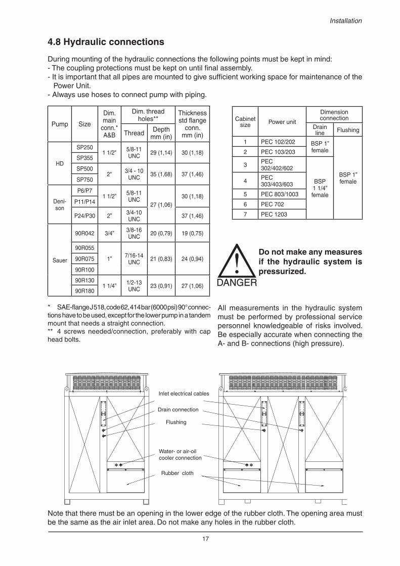
4.8 Hydraulic connections
During mounting of the hydraulic connections the following points must be kept in mind:- The coupling protections must be kept on until fi nal assembly.- It is important that all pipes are mounted to give suffi cient working space for maintenance of the
Power Unit.- Always use hoses to connect pump with piping.
Do not make any measures if the hydraulic system is pressurized.
* SAE-fl ange J 518, code 62, 414 bar (6000 psi) 90° connec-tions have to be used, except for the lower pump in a tandem mount that needs a straight connection. ** 4 screws needed/connection, preferably with cap head bolts.
Installation
All measurements in the hydraulic system must be performed by professional service personnel knowledgeable of risks involved. Be especially accurate when connecting the A- and B- connections (high pressure).
Note that there must be an opening in the lower edge of the rubber cloth. The opening area must be the same as the air inlet area. Do not make any holes in the rubber cloth.
Drain connection
Flushing
Water- or air-oil cooler connection
Rubber cloth
Inlet electrical cables
18
Installation and Maintenance Manual, Power Unit PEC
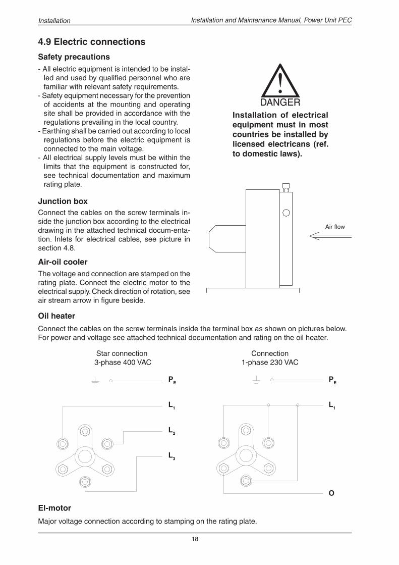
Oil heater
Connect the cables on the screw terminals inside the terminal box as shown on pictures below.For power and voltage see attached technical documentation and rating on the oil heater.
Star connection 3-phase 400 VAC
Connection 1-phase 230 VAC
4.9 Electric connections
- All electric equipment is intended to be instal-led and used by qualifi ed personnel who are familiar with relevant safety requirements.
- Safety equipment necessary for the prevention of accidents at the mounting and operating site shall be provided in accordance with the regulations prevailing in the local country.
- Earthing shall be carried out according to local regulations before the electric equipment is connected to the main voltage.
- All electrical supply levels must be within the limits that the equipment is constructed for, see technical documentation and maximum rating plate.
Safety precautions
The voltage and connection are stamped on the rating plate. Connect the electric motor to the electrical supply. Check direction of rotation, see air stream arrow in fi gure beside.
Air-oil cooler
Connect the cables on the screw terminals in-side the junction box according to the electrical drawing in the attached technical docum-enta-tion. Inlets for electrical cables, see picture in section 4.8.
Junction box
Air fl ow
Installation
L 3
2L
1L
EP
O
1L
EPPE
L1
L2
L3
PE
L1
O
El-motor
Major voltage connection according to stamping on the rating plate.
Installation of electrical equipment must in most countries be installed by licensed electricans (ref. to domestic laws).

19
Installation and Maintenance Manual, Power Unit PEC
Cooling water must fulfi l required fl ow, pressure, temperature and cleanliness level (see attached technical documentation and section “Cooling water“). Otherwise the reliability of the entire drive will be reduced. It is important that all piping on the Unit is performed so that suffi cient working space for maintenance is obtained. The water-pipes and the cooler may need to be insulated to prevent condensing water and freezing in winter condition.
Storage of included componentsThe included components shall be stored according to section “Storage of the packed Power Unit“. Notice that the packing must not be removed during storage.
4.10 Water connections
Installation
C1 in
C2 out C2 out
C1 in
4.11 Pipework
General
The Power Unit should be placed as close to the hydraulic motor as possible, taking other circum-stances (such as space, environmental conditions et cetera) into consideration.
Do not work on the pipework if the hydraulic system is pressurized. Use necessary safety equipment during installation of the pipe work.Usual safety requirements for each measure must be followed.
The main connections of the drive pump and the hydraulic motor must always be fi tted to the piping with hoses. We recommend there be shut off valves on the main lines A & B. The protections on all parts must be kept on until fi nal assembly.
Water

20
Installation and Maintenance Manual, Power Unit PEC
Handling of fi ttingsGeneral: Inspect the sealing surfaces on the couplings visually before mounting. It must be free from any damages such as scores and cracks. Handle the couplings with care. If you drop the coupling or it has nicks on it inspect it visually. Check that the sealing (if any) is in its right position, free from cracks and that it is saturated with oil .
The protections and packings on the fi ttings must be kept on until fi nal assembly.
Mounting of hosesEnsure that hoses are not stressed or twisted on installation, so as to prevent premature fail-ure. Bend radius should conform to manufac-turers recommendations.
Clamps The normal distance between clamps: D ≤ 25 mm (1 in) 1500 - 2000 mm (59 - 79 in).D ≥ 25 mm (1 in) 2000 - 2500 mm (79 - 98 in).The pipes must be clamped immediately before and after a bend and immediately before transi-tion to a hose.
Cleaning The pipes and hoses should be pre cleaned, inspected and sealed by the supplier. If the pipes are fi eld bent and installed the overall system must be oil fl ushed to reach the required clean-liness level.
Installation
Right
WrongRight
Right
Right
Right
Wrong
Wrong
Wrong
Wrong
Right
Wrong
Flange fi ttings: The screws must be tightened crosswise.
Jic-fi ttings (SAE J514, ISO 8434): Moment of tightening; by hand +1/4 - 1/2 turn.
Do not overtighten the fi ttings.
Use correct size tools, fi ttings can be damaged and diffi cult to remove.
Notice that all fi ttings may expand because of heat and vibrations and must be retightened.
Pressure testsPressure tests should always take place before fl ushing in order to release contaminations by stres-ses introduced by the pressure. The main lines must be pressure and leakage tested to a static pressure of 1,5 x max. expected system pressure (not above bursting pressure). The hydraulic motor and Power Unit must be disconnected or protected by closed valves during the pressure tests. The tests on the main lines are appr. carried out by using a hydraulic hand pump.
Welded fi ttings:Contact your Hägglunds Drives representative.

21
Installation and Maintenance Manual, Power Unit PEC
4.13.2 Filling up the system with hydraulic fl uid
- Check that the correct type and quality of hy-draulic fl uid is used. Do not mix different types of hydraulic fl uid without fi rst checking with manufacturers.
- Check that the barrel with hydraulic fl uid and tank/hoses are not contaminated with water or other substances.
4.13 Commissioning
4.13.1 Before commissioning
- Read and understand this complete manual and the other attached technical documentation. - Visually check the whole system for: signs of damage, incorrect circuitry, security of foundations,
is the degree of fi ltration for the fi lter according to the data in the technical documentation.- Check that the coupling between the electric motor and pump is properly mounted.- Check that the precharge pressure in the accumulator (option) is in accordance with the attached
technical documentation and/or check the precharge pressure on the label close to the accumu-lator. How to check precharge pressure, see page 10.
Electrics
- Check that electric motor(s), control system and other electrical components are con-nec-ted to the correct voltages.
- Check the function of electrical components and monitoring system manually. Instruments that cannot be actuated can be checked for correct wiring and possibly operated manually. Level switch and indication should be checked when fi lling up the tank.
Pipe work- Are the couplings properly tightened? - Is the pipe work properly cleaned?- Is the pipe work mounted free of stress?- Are the lines in accordance with installation
drawing/piping plan?
Cleanliness
- The hydraulic system must be fl ushed and thoroughly cleaned on the inside.
- If the slightest doubts are entertained, the cleanliness should be checked before fi lling with oil.
General
Before fi lling
Installation
4.12 Flushing before start upA pressure fi lter and checkvalve has to be connected to the main line at the Power Unit. This fi lter is connected on the return side of the drive pump.
Hoses connected together
Flow direction
Flushing fi lter
Check valve
Power Unit
Rec. fi ltration degree β10 = 75 or better.
The size of the fl ushing fi lter should be matched to that of the pump concerned, so that the pres-sure drop across the fi lter is not excessive and that the max. pressure/fl ow ratings for the fi lter is not exceeded.
The main lines should be connected together at the motor enabling the entire system to be fl ushed, see fi gure beside.
The maximum fl ow from the Power Unit should be fl ushed through the main circuit for at least 2 hours on small installations and considerably longer on large ones.
- For handling of couplings and hoses see sec-tion “Pipe work“
- Plug the drain connection Dx(motor) to pre-vent non fi ltered fl uid being fl ushed into the hydraulic motor case, when fi lling the system the fi rst time.
Use extreme caution to ensure pump is stroked in sync with free fl ow direction of check valve.
Use a check valve sized for the oil fl ow.
When using the main pump the max. pressure should be reduced.

22
Installation and Maintenance Manual, Power Unit PEC
Volume litre (US gallon)
Power UnitPEC
102/103PEC
202/203PEC
302/303PEC
402/403PEC
602/603PEC 803
PEC 1003
PEC 702
PEC 1203
Max (visual level gauge on tank)
171 (45,1)
236 (62,3)
308 (81,3)
396 (104,5)
517 (136,5)
857 (226,2)
994 (262,4)
715 (188,9)
1240 (327,6)
Between levels, max - warning
27(7,1)
32(8,4)
36(9,5)
47 (12,4)
49 (12,9)
82 (21,6)
89 (23,5)
65 (17,2)
102 (27,0)
Filling
Use an fl uid fi lling pump unit which has a fi lter with a fi lter rating of 10 microns or better.
Always pump the fl uid in through the special quick connection which is marked appropriately. The quick connection is a completely rust-proof quick release coupling, see fi gure below. The fl uid fi lled into the system will be fi ltered through the drain fi lter for better results.
The tank must be fi lled with oil to 20 mm (0,79 in) below the maximum level on the visual level gauge on tank before starting for the fi rst time.
Check the function of the level -switch and -indication during fi lling up of the tank.
femaleBSPP 1"
- Check the caution sign on the hydraulic fl uid container and the war-nings in section “Choice of hydraulic fl uid”.
- Avoid long contact with the skin and the hydraulic fl uid.- Remove any spilled oil from the fl oor, great risk to slip and fall.
Filling up the system with hydraulic fl uid
After the fl uid fi lling open up the drain line and reconnect the drain line from the hydraulic motor.
Installation
New fl uid is normally not fi ltered and will introduce dirt into the system, the fl uid must therefor always be fi lled through a fi lter. Never pour hydraulic fl uid into the tank through the air breather fi lter.
BSPP 1" female

23
Installation and Maintenance Manual, Power Unit PEC
STEP 2Start with unloaded pump at short intervalsStarting of the power unit shall be carried out with a completely unloaded pump in short intervals.
4.13.3 Initial start up procedure
- When the hydraulic fluid is cold some restarts may be needed to raise the charge pressure.
- Check the charge pressure confi rm with data and settings on attached technical documentation.
- If OK, the pump may be allowed to come on stroke and introduce fl ow into the unloaded hydraulic system. Check that the charge pressure is still OK.
- Make sure the driven system and driven machine is ready to run, warn all personel in the area that start up is imminent.
- Follow "Safety precautions" section 1.1.- Never operate the Power Unit with defective instruments or control elements.- Keep infl ammable materials away from the Power Unit.- During start-up period, the hydraulic system will be cleaned from built-in dirt particles, therefore
keep an eye on the fi lter indicator during the entire starting up procedure.
On cold start up, the fi lters may indicate bypass. After a few minutes of operating, press down the visual indicator to reset. If the indicators will not reset after system has reached operation tempe-rature, fi lter element must be changed.
STEP 1Immediately before starting- Check fl uid level in the tank and refi ll to about 20 mm (0,79 in) below max level at visual level
gauge on tank (see “fi lling up the system with hydraulic fl uid“).- Check if any components need fi lling with clean hydraulic fl uid, i.e. pump case or motor case.- Check safety equipment.- Check that the prescribed steps in section “Before starting up“ have been carried out.- Make sure that all valves on the suction, pressure and inlet side of the pump, as well as any
valves on drain lines, are open.- Check that cooling water is connected and turned on if a water- oil cooler is used. For adjustments and settings on the control system (if any) see special instruction in attached technical documentation.
Installation
Note!
Make sure immediately that the pump has the correct direction of rotation, otherwise the pump will be damaged. The correct directon of rotation is evident from a sign placed under the electric motor, see fi gure below.

24
Installation and Maintenance Manual, Power Unit PEC
STEP 3Unloaded pump at longer intervals
Run for a period at no load condition until system is stable and control is established.
Topping up may be needed due to parts of the system having been fi lled with fl uid.
- Check for unusual noises or vibrations.- Check that the specifi ed pressure levels for charge pressure and pilot* pressure at the Power Unit
are maintained in accordance with the values stated on the hydraulic diagram in the attached technical documentation. These pressure levels are preset at the factory and there is normally no need to readjust.*only on the Hägglunds Drives pump
- Check for leakage points.
Stop the electric motor
- Correct any faults discovered on the points above.- Check all connections, screws etc. and tighten if it is necessary. - Restart when fi nished .
STEP 5Checking - Check for unusual noises or vibrations.- Check the function of the safety equipments.- Check temp in tank and cloosed loop. Check also that the cooler control is stable. If not, investi-
gate water supply, controls, air blast cooler, etc.- Check for leakage points.- Check that the pump compensator pressure control and pressure switches (optional) are set at
levels appropriate to the drive. Upon delivery, these pressure levels are set at the levels specifi ed by the customer and normally no readjustment will be necessary. The values are stated in the technical documentation, data and settings. Pressure can easily be checked by closing a ball valve on the high pressure leg and stroking the pump until the pressure is showing on the gauge.
- The working pressure must be checked to ensure that they correspond to the contracted va-lues.
STEP 6Stop the electric motor- Correct any faults discovered at the points above. - Check the fi lter indicator. It is not unusual to change elements on commisioning as the system is
cleaning the dirt particles out. When changing fi lter elements carefully follow the instructions in section “Filter change“ to prevent introduction of dirt into the system.
If there is still dirt in the system, additional fl ushing is necessary in order to prevent premature failure of system components.
- Check all connections, screws etc. and tighten if it is necessary. - Tidy up inside and around the Power Unit. Remove waste fl uid, pieces of cable among other
things. Keep the inside of the Power Unit neat and clean.
STEP 4Loaded hydraulic systemThe hydraulic system can be loaded when the hydraulic system functions satisfactorily in unloa-ded running condition.
- Gradually increase load pressure until satisfactory operation is obtained.- It may be necessary at this point to make adjustments to fl ow, ramp rates, etc.- Cycle the system until normal operating temperature is reached.
Installation
Check fl uid level in the tank
Initial start up procedure

25
Installation and Maintenance Manual, Power Unit PEC Installation
4.14 Pump settings and adjustments4.14.1 Hägglunds Drives, SP-pump
Charge pressure level, control pressure level, high pressure relief valves and pressure compen-sator are set before the delivery of Power Units from the factory and there is normally no need for readjustment. Check always the pressure levels in the documentation. Setting of pressures on the pump(s) must be performed by skilled service personnel familiar with functions and risks involved with the pump. The pressures shall be set during operation and with system at operating temperature.Note that pressures will change with different viscosities.
1. Charge pressure adjustment: Stroke out the pump to more than 50 % and increase the high pressure up to Php > 100 bar by loading an actuator. Release the luck nut width size 19 and adjust the charge pres-sure to the necessary level by turning the setting screw (internal hexagon size 6). The charge pressure shall be set at 15 bar/218 psi as standard. Pressure to be measured at port MK4-port. After adjustment tighten the setting screw by means of the luck nut size 19.
2. Control pressure adjustment: The control pressure to be measured at port E2. The control pressure shall be adjusted to 30 bar/436 psi + (pn - ps) with the pump in neutral (zero stroke position).
Release the luck nut width size 19 and adjust the control pressure to the necessary level by turning the setting screw (internal hexagon size 6).To get the value pn measure the pressure in ME3-port with the pump in neutral. To get the value ps measure the pressure in ME3-port with the pump swiveled out to >50 % stroke (Secure that the fl ushing valve has moved).(pn - ps) = should be about 5-12 bar, depending on the pump size. After adjustment tighten the setting screw by means of the luck nut size 19
3. High pressure relief valves setting A and B side: Set the compensator pressure (See item 4.) to a value corresponding to the high pressure relief valve seeting. The reason for that is to be able to reach enough high pressure at the pressure relief valve setting. Release the luck nut (width size 24) and adjust the set-ting screw (internal hexagon size 6). With loaded pump (blocked or partly blocked main port or actuator) increase the high pressure relief valve setting until the pump starts to swivel out. Setting value according to documentation, maximum 390 bar. With completely blocked port the swivel angle shall be below 3º. Measure the pressure at port MA resp. MB. The setting value shall be 40 bar above the compensator pressure setting.
N.B. The high pressure relief valves must be adjusted before the compensator pressure adjust-ment.
4. Pressure compensator setting: Release the luck nut (width size 17) and adjust the setting screw (internal hexagon size 5). The pressure compensator shall be adjusted with blocked main-port or blocked actuator. Set the compensator pressure to a value according to the documentation, maximum 350 bar. Measure the pressure at port MA resp. MB
# 009839960098399697.1001.00.00097.1001.00.000GEZ AdapterGEZ Adapter-- M14x1.5 / 9/16-18UNF-2BM14x1.5 / 9/16-18UNF-2B00100120
#02417968
97.6680.32.70097.6680.32.700
GE
ZV
erstellung/CO
NT
RO
LG
EZ
Verstellung/C
ON
TR
OL
--A
4VS
G 250 E
PG
/30R-S
1269A
4VS
G 250 E
PG
/30R-S
1269002
30
Magnet A
SOLENOID A
Magnet B
SOLENOID B
Einschraubloch M8
Einschr aub loc h M8
Einschr aubloch M14
Einschra ubloch M14
M5 (x0.8)
M5 (x0.8)
Einschr aubloch M14
Ei n schraubloch M14
Einschr aubloch M8
Einschr aub loch M8
Einschr aub loch M8
Einschr aub loc h M8
M5 (x0.8)
M5 ( x0. 8)
M5 (x0.8)
M5 (x0.8)
M5 (x0.8)
M5 (x0.8)
M5 (x0.8)
M5 ( x 0.8)
M 8
M 6
Einschr aub loch M14
Ei ns c hra u bl och M14
UNC 9/16"-12UNC 9/16"-12
Schl.weite: 30 mm
S chl.weite:30 mm
M14x1.50M14x1.50M14x1.50M14x1.50
Schl.weite:30 mm
S chl .weite :30 mm
#0242292702422927
97.2020.35.74297.2020.35.742
GE
Z G
rundeinheit/BA
SE
UN
ITG
EZ
Grundeinheit/B
AS
E U
NIT
--A
4CS
G 355 O
V/3X
X-X
XB
85FX
XX
X -S
1325A
4CS
G 355 O
V/3X
X-X
XB
85FX
XX
X -S
1325001
30
R(L)
Einschraubloch 1 5/8"E inschraubloch 1 5/8"
Einschr aubloch M18
Eins chrau bloch M1 8
Einschr aubloch M18
Eins chr aub loch M18
Einschraubloch M18
Einschraubloch M18
Einschr aub loch M14
Ei nsc hr aub loch M14
Einschraubloch M14
Ei nsc hrau bl och M14
M6 (x1)
M6 (x1)
0
M39x1.50M39x1.50
M 6
Einschraubloch M14Einschraubloch M14
M 8
Einschraubloch 9/16"Einschraubloch 9/16"
Einschraubloch M14Einschraubloch M14
Einschraubloch 9/16"Einschraubloch 9/16"
Einschraubloch M14Einschraubloch M14
Einschraubloch M14Einschraubloch M14
Einschraubloch M33Einschraubloch M33
Einschraubloch M42Einschraubloch M42
Einschraubloch M42Einschraubloch M42
M12 (x1.75)M12 (x1.75)M12 (x1.75)M12 (x1.75)
M12 (x1.75)M12 (x1.75)M12 (x1.75)M12 (x1.75)
# 009212540092125490.5420.00.91690.5420.00.916VERSCHL.SCHR. WN1048VERSCHL.SCHR. WN1048---- 9/16-18UNF 2A FPM9/16-18UNF 2A FPM----2020
#026502230265022390.6421.00.00090.6421.00.000DBV MHDBV 40 K2-1x/420XYVDBV MHDBV 40 K2-1x/420XYV----0010014040
# 009212540092125490.5420.00.91690.5420.00.916VERSCHL.SCHR. WN1048VERSCHL.SCHR. WN1048---- 9/16-18UNF 2A FPM9/16-18UNF 2A FPM----2020
Einschraubloch M33Einschraubloch M33
Einschraubloch M42Einschraubloch M42
M39x1.50M39x1.50
Einschraubloch M14Einschraubloch M14
Einschraubloch 9/16"Einschraubloch 9/16"
M 12M 12
Einschraubloch 9/16"Einschraubloch 9/16"
# 024056510240565197.2124.40.70097.2124.40.700Vent.Einbaus.Vent.Einbaus.---- A4CSG 500A4CSG 500----6060 Einschraubloch M42Einschraubloch M42
#024037930240379397.6680.45.70097.6680.45.700GEZ VerstellungGEZ Verstellung---- A4VSG 750 HDA /30A4VSG 750 HDA /300010013030
R
L R#
0098491900984919
97.2020.45.74297.2020.45.742
GE
ZG
r undeinheitG
EZ
Grundeinheit
----A
4VS
G750 O
V/3X
X-X
XH
10XX
XA
4VS
G750 O
V/3X
X-X
XH
10XX
X002002
3030
15%%12715%%12715%%12715%%1270
Einschraublo ch M
2 7E
inschraubloch M27
M6 0 x 2
M60x2
M1 6 (x2 )
M16 (x2)
M1 6 ( x 2 )
M16 (x2)
M8 (x 1 .2 5 )
M8 (x1.25)
Schl.weite: 22 mmSchl.weite: 22 mmSchl.weite: 22 mmSchl.weite: 22 mm
Schl.w
eite :2 7 mm
Schl.w
eite: 27 mm
Sc h l . w
e ite :2 7 mm
Schl.w
eite: 27 mm
Sc h l.w
e i te :2 4 mm
Schl.w
eite: 24 mm
Sc h l.w
e ite :2 4 mm
Schl.w
eite: 24 mm
M 10M 10
M 6M 6
M 6M 6
M1
M10x1.00M10x1.00M8 (x1.25)M8 (x1.25)
M10x1.00M10x1.00
M10x1.00M10x1.00M8 (x1.25)M8 (x1.25)
M27x2.00M27x2.00
M8 (x1.25)M8 (x1.25)
M8 (x1.25)M8 (x1.25)
M8 (x1.25)M8 (x1.25)
SP250-SP355 SP500-SP750
# 0092240890.5440.24.060Zyl.Schr. DIN912Zyl.Schr. DIN912-- M24X60 -10.9M24X60 -10.9--20# 0092240890.5440.24.060Zyl.Schr. DIN912-- M24X60 -10.9--20
# 0092240890.5440.24.060Zyl.Schr. DIN912Zyl.Schr. DIN912-- M24X60 -10.9M24X60 -10.9--20# 0092240890.5440.24.060Zyl.Schr. DIN912-- M24X60 -10.9--20
1K
4K A
E 1
E 2
E 3
BEinschraubloch 1 5/16" (Form X)Einschraubloch 1 5/16" (Form X)
M16 (x2) M16 (x2)M16 (x2)
M16 (x2)M16 (x2)M16 (x2)
S
M20 (x2.5)
M20 (x2.5) M20 (x2.5)
M20 (x2.5)
Einschraubloch 1 5/16" (Form X)Einschraubloch 1 5/16" (Form X)Einschraubloch 1 5/16" (Form X)Einschraubloch 1 5/16" (Form X)
#00
9212
4600
9212
4690
.542
0.10
.516
VE
RS
CH
L.S
CH
R.W
N10
48V
ER
SC
HL.
SC
HR
.WN
1048
--1
5/16
-12U
NF
2A
FP
M1
5/16
-12U
NF
2A
FP
M--11
%%
132%
%u%
%o*
*%%
u%%
o%%
133
#0241825497.4148.32.700GEZ Anschlussplatte/PORT PLATE-- A4CSG 250/3XX-XXB85KXX4D -S123400120
B
Compensator pressure settingCompensator pressure setting
High pressure relief valve A
Control pressure relief valve
Charge pressure relief valve
High pressure relief valve B

26
Installation and Maintenance Manual, Power Unit PEC
View from the back View from the back Front view
Charge pressure adj.
Charge pressure adjustment
P6S, P7S, P11S & P14S P24S & P30S
4.14.2 Denison pump
Charge pressure and Pump compensator pressure level are set before the Power Units leave the factory and consequently there is normally no need for readjustment.Check always the pressure levels in technical documentation. Setting of pressures on the pump(s) must be performed by professional service personnel familiar with the functions and risks involved with the pump. The pressures shall be set during operation and with the system at operating temperature. Note that pressures can change with different viscosities.
1. Charge pressure adjustment: Remove acorn nut, loosen lock nut and adjust pressure with an allen key, size 5/32". Clockwise adjustment will increase the pressure. The charge pressure (on the charge pres-sure gauge) shall be within the following limits: 15 bar/218 psi (for P6S/ P7S & P11S/P14S & P24S) and 15 bar/261 psi (for P30S).
If other charge pressures are to be set, contact Hägglunds Drives representative for consultation.
2. When charge pressure is set: Tighten lock nut and return acorn nut. Note in the logbook or technical documentation.
Installation
Compensator valve
1. If the main pressure levels are to be increased: Make sure that the piping and machine structure can take higher pressure/higher torque delivered from the hydraulic motor.
2. Compensator pressure adjustment: Activate or move the input signal to the control so that pressure in-creases in the high pressure closed circuit to the pressure limiter setting. The pressure limiter setting is reached when the pressure stops increasing and remains steady at a given pressure level. (as shown on the gauges)
The pressure limiter setting for both A- and B-side is set on the compensator valve.
Remove acorn nut, loosen lock nut and adjust pressures with an allen key, size 5/32", until the desired pres-sure level is established. Clockwise rotation of the adjustment screw will increase the pressure.
3. When main pressures are set: Tighten lock nut and return acorn nut. Note the new pressure level in log-book or technical documentation.
Working in high pressure areas could be dangerous in case of unforeseen failures.
27
Installation and Maintenance Manual, Power Unit PEC
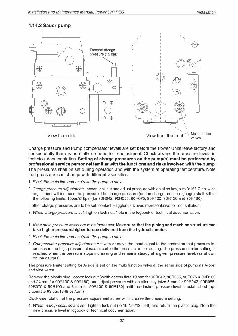
1. If the main pressure levels are to be increased: Make sure that the piping and machine structure can take higher pressure/higher torque delivered from the hydraulic motor.
2. Block the main line and onstroke the pump to max.
3. Compensator pressure adjustment: Activate or move the input signal to the control so that pressure in-creases in the high pressure closed circuit to the pressure limiter setting. The pressure limiter setting is reached when the pressure stops increasing and remains steady at a given pressure level. (as shown on the gauges)
The pressure limiter setting for A-side is set on the multi function valve at the same side of pump as A-port and vice verca.
Remove the plastic plug, loosen lock nut (width across fl ats 19 mm for 90R042, 90R055, 90R075 & 90R100 and 24 mm for 90R130 & 90R180) and adjust pressure with an allen key (size 5 mm for 90R042, 90R055, 90R075 & 90R100 and 8 mm for 90R130 & 90R180) until the desired pressure level is established (ap-proximate 93 bar/1348 psi/turn)
Clockwise rotation of the pressure adjustment screw will increase the pressure setting.
4. When main pressures are set: Tighten lock nut (to 16 Nm/12 lbf·ft) and return the plastic plug. Note the new pressure level in logbook or technical documentation.
Multi function valvesView from side View from the front
4.14.3 Sauer pump
Charge pressure and Pump compensator levels are set before the Power Units leave factory and consequently there is normally no need for readjustment. Check always the pressure levels in technical documentation. Setting of charge pressures on the pump(s) must be performed by professional service personnel familiar with the functions and risks involved with the pump. The pressures shall be set during operation and with the system at operating temperature. Note that pressures can change with different viscosities.
1. Block the main line and onstroke the pump to max.
2. Charge pressure adjustment: Loosen lock nut and adjust pressure with an allen key, size 3/16". Clockwise adjustment will increase the pressure. The charge pressure (on the charge pressure gauge) shall within the following limits: 15bar/218psi (for 90R042, 90R055, 90R075, 90R100, 90R130 and 90R180).
If other charge pressures are to be set, contact Hägglunds Drives representative for consultation.
3. When charge pressure is set: Tighten lock nut. Note in the logbook or technical documentation.
External charge pressure (15 bar)
Installation
28
Installation and Maintenance Manual, Power Unit PEC
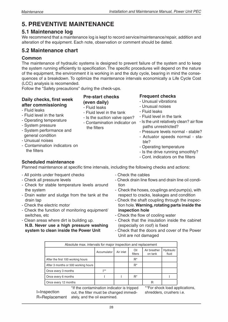
Scheduled maintenancePlanned maintenance at specifi c time intervals, including the following checks and actions:
5.2 Maintenance chartCommonThe maintenance of hydraulic systems is designed to prevent failure of the system and to keep the system running effi ciently to specifi cation. The specifi c procedures will depend on the nature of the equipment, the environment it is working in and the duty cycle, bearing in mind the conse-quences of a breakdown. To optimize the maintenance intervals economically a Life Cycle Cost (LCC) analysis is recomended.Follow the "Safety precautions" during the check-ups.
Daily checks, fi rst week after commissioning- Fluid leaks- Fluid level in the tank- Operating temperature- System pressure- System performance and general condition- Unusual noises- Contamination indicators on
the fi lters
Frequent checks- Unusual vibrations- Unusual noises- Fluid leaks- Fluid level in the tank- Is the unit relatively clean? air fl ow
paths unrestricted?- Pressure levels normal - stable?- Actuator speeds normal - sta-
ble?- Operating temperature- Is the drive running smoothly?- Cont. indicators on the fi lters
Maintenance
Pre-start checks (even daily)- Fluid leaks- Fluid level in the tank- Is the suction valve open?- Contamination indicator on
the fi lters
R=ReplacementI=Inspection
*If the contamination indicator is tripped out, the fi lter must be changed immedi-ately, and the oil examined.
- Check the cables- Check drain line fl ows and drain line oil condi-
tion- Check the hoses, couplings and pump(s), with
respect to cracks, leakages and condition- Check the shaft coupling through the inspec-
tion hole. Warning, rotating parts inside the inspection hole
- Check the fl ow of cooling water- Check that the insulation inside the cabinet
(especially on roof) is fi xed- Check that the doors and cover of the Power
Unit are not damaged
- All points under frequent checks- Check all pressure levels- Check for stable temperature levels around
the system- Drain water and sludge from the tank at the
drain tap- Check the electric motor- Check the function of monitoring equipment/
switches, etc- Clean areas where dirt is building up.
N.B. Never use a high pressure washing system to clean inside the Power Unit
5. PREVENTIVE MAINTENANCE5.1 Maintenance logWe recommend that a maintenance log is kept to record service/maintenance/repair, addition and alteration of the equipment. Each note, observation or comment should be dated.
**For shock load applications, shredders, crushers i.e.
Absolute max. intervals for major inspection and replacement
Accumulator Air inletOil
fi ltersAir breather
on tankHydraulic
fl uid
After the fi rst 100 working hours R*
After 3 months or 500 working hours R*
Once every 3 months I**
Once every 6 months I I R* I
Once every 12 months R
29
Installation and Maintenance Manual, Power Unit PEC
�
� �� ��
�
�
A B
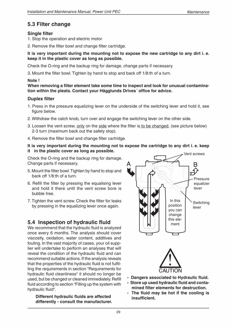
Single fi lter1. Stop the operation and electric motor
2. Remove the fi lter bowl and change fi lter cartridge.
It is very important during the mounting not to expose the new cartridge to any dirt i. e. keep it in the plastic cover as long as possible.
Check the O-ring and the backup ring for damage, change parts if ne cessary.
3. Mount the fi lter bowl. Tighten by hand to stop and back off 1/8:th of a turn.
Note !When removing a fi lter element take some time to inspect and look for unusual contamina-tion within the pleats. Contact your Hägglunds Drives´ offi ce for advice.
Duplex fi lter
1. Press in the pressure equalizing lever on the underside of the switching lever and hold it, see fi gure below.
2. Withdraw the catch knob, turn over and engage the switching lever on the other side.
3. Loosen the vent screw, only on the side where the fi lter is to be changed, (see picture below) 2-3 turn (maximum back out the safety stop).
4. Remove the fi lter bowl and change fi lter cartridge.
It is very important during the mounting not to expose the cartridge to any dirt i. e. keep it in the plastic cover as long as possible.
Check the O-ring and the backup ring for damage. Change parts if necessary.
- Dangers associated to Hydraulic fl uid.- Store up used hydraulic fl uid and conta-
mined fi lter elements for destruction.- The fl uid may be hot if the cooling is
insuffi cient.
Vent screws
5.3 Filter change
5.4 Inspection of hydraulic fl uidWe recommend that the hydraulic fl uid is analyzed once every 6 months. The analysis should cover viscosity, oxidation, water content, additives and fouling. In the vast majority of cases, your oil supp-lier will undertake to perform an analyses that will reveal the condition of the hydraulic fl uid and can recommend suitable actions. If the analysis reveals that the properties of the hydraulic fl uid is not fulfi l-ling the requirements in section “Requirements for hydraulic fl uid cleanliness“ it should no longer be used, but be changed or cleaned immediately. Refi ll fl uid according to section “Filling up the system with hydraulic fl uid“.
5. Mount the fi lter bowl. Tighten by hand to stop and back off 1/8:th of a turn.
6. Refi ll the fi lter by pressing the equalising lever and hold it there until the vent screw bore is bubble free.
7. Tighten the vent screw. Check the fi lter for leaks by pressing in the equalizing lever once again.
Different hydraulic fl uids are affected differently - consult the manufacturer.
Maintenance
Pressure equalizer lever
Switching lever
In this position you can change this ele-
ment

30
Installation and Maintenance Manual, Power Unit PEC
Lubrication intervals ABB electric motor (50Hz)
Frame size
El-motor Rated Power (kW)
Lubrication intervals in duty hours
200 30
3200225
37
45
250 55
3000280
75
90
315
110
2700132
160
200
355
250
2500315
355
400
400 500 2500
Lubricate electrical motors larger than 30 kW.1. Clean the grease nipples.2. Grease the electrical motor, use a grease gun.
GreaseWhen regreasing, use only special ball bearing grease with the following properties:- good quality lithium base or lithium complex grease- base oil viscosity 100-140 cSt at 40°C (476-667 SSU at 104°F).- consistency NLGI grade 2 or 3- temperature range -30°C - +120°C, continously (-22°F - +248°F).
Grease with the right properties are available from all the major lubricant manufacturers. If the type of grease is changed and compatability is uncertain, lubricate several times at short intervals in order to displace the old grease.
5.6 Air fi lter change1. Clean around the area where the air fi lter
is located.2. Unscrew the cap and change the fi lter.3. Mount the cap and make sure that no foreign material has entered the oil tank.
Air inlet for electrical motorCheck that the air inlets on the cabinet top cover and on the electric motor are not clog-ged by dirt and that air can easily pass.
5.5 Lubrication of electric motor (valid for ABB-motors)
Maintenance
Grease nippels
Check the warning label on the grease cartridge.
31
Installation and Maintenance Manual, Power Unit PEC
Periods out of commissioningClean and empty the cooling system (water side) before periods of rest (especially if the cooling water is not totally clean). If the Power Unit is to be out of service for more than three months, the hydraulic system must be protected internally against rust. This can be done in the following manner:Use hydraulic fl uid with rust preventing additives according to ASTM D665 class A or hydraulic fl uid similar to Shell corr. hydraul, 2% VSI-improver. This additive gives protection against rust for up to about a year. After this, the equipment should be run at intervals so as to maintain a protective fi lm on the internal surfaces of components and oil lines, thus providing protection against corrosion.If any parts of the system are disconnected, note that open fi ttings must be protected by plugs or covers to prevent ingress of any dirt particles.
Re-commissioning Before the plant is re-started after a long idle period, a check should be made as to whether the instructions supplied for the original commissioning still apply. Moreover, the following measures should be observed.-Remove preservative solution and any signs of contamination.-Follow the procedure in section “Initial start up procedure“
5.8 Cleaning of Air-Oil cooler
Cleaning of air fi ns- The easiest way to clean the air fi ns is by using
compressed air or rinsing with water.- Fouling can be dealt with using a degreasing
agent and a high-pressure washing system. When using a high pressure washing system point the jet carefully parallel to the air fi ns.
Cleaning the inside of oil cooling pipesConnect the cooler to a closed circuit and fl ush the inside with perchloroethylene. After cleaning the radiator should be fl ushed with fl uid before reconnecting to the hydraulic system.
Follow the safety precautions on the container of the cleaning agent used. Disconnect the Power Unit before disconnecting the water-oil/Air-oil cooler. Make sure that electric power is cut off before cleaning! Cleaning agent and waste water from rinsing should not be desposed in nature.
Maintenance
5.9 Power Unit out of service
5.7 Cleaning of Water-Oil cooler
- Back-fl ushing with water will remove most soft deposit.
- If fouling appears in the form of hard deposits, circulate a weak acid through the cooler in reverse direction to the normal waterfl ow. Use 5% phosphoric acid or, for frequent cleaning, 5% oxalic acid or similar weak organic acid. Afterwards rinse with a large quantity of water to fl ush all acid from the cooler before starting up the system again.
Never wait until the cooler is completely clogged before cleaning.

32
Installation and Maintenance Manual, Power Unit PEC
6. CORRECTIVE MAINTENANCE6.1 Common
Before disassembly:- Trouble-shoot the Power Unit and perform appropriate tests.- Clean all assemblies and components, take all precautions necessary to prevent dirt entering
the system.- Disassembly may only be done by professional service personnel.
Disassembly:- Label all parts, and protect precision or machined surfaces.- Inspect all parts during disassembly for wear or damage.- If hydraulic fl uid is to be drained and reused, make sure that drain containers are clean and co-
vered when not in use.- Clean all metal parts using a suitable solvent prior to reassembly, set aside on a clean and lintfree
cloth to drain.
Reassembly:- Lubricate with system hydraulic fl uid- Replace all seals, gaskets and o-rings with new items of the correct size.- Ensure complete sealing at pipe connections- Refi ll hydraulic fl uid according to section “Filling up the system with hydraulic fl uid“.
Before removing any hydraulic/electric components, disconnect the Power Unit. Ensure that no energy is accumulated in the system and the electric motor currentless. Be watchful on the section "Safety precautions".
6.2 Change of electric motor/pump unit.
The most common method to change the pump is to lift the complete electric motor/pump unit and then remove the pump. The electric motor and pump are assembled into a unit and mounted on the motor support plate attached to the frame via antivibration elements.
1. Remove roof and sound baffl e : See section “Mounting of electric motor“ item 1 and 2. 2. Release the motor support plate : Release the motor support plate from the frame.3. Adapt lifting equipment : Adapt lifting equipment in the four holes in the corners of the motor
support plate.4. Lift the el-motor/pump unit : Be careful and take the weight and centre of gravity into consi-
deration. Never let the electric motor/pump stand on the charge pump.5. Assemble : Assemble in reverse order according to point 4 to 1.
- Always use all four lifting points when lifting the electric motor/pump unit.- Never use the lifting ears on the electric motor to lift the complete electric motor/
pump unit.- Use only lifting equipment adapted to the weight (for weights see section “Lifting
methods and weights“)- Do not stand under hanging load- Take centre of gravitation into consideration during lifting
Corrective maintenance

33
Installation and Maintenance Manual, Power Unit PEC
Fault Probable cause ActionPower Unit does
not start
Main voltage to electric motor
lacking.
Look for the cause in the electric power network.
Control voltage lacking. Look for the cause in the electric power supply
network. Examine the control system in the power
unit. If the control system has tripped, determine
the reason.
Power Unit fails
to deliver oil fl ow.
No servo pressure. No control current to electro hydraulic stroker
control. Examine the control function or electronic
control card.
Coupling pump/el-motor defect. Check through the inspection hole in the bellhou-
sing.
Wrong direction of rotation
hydraulic pump.
Check direction of rotation.
Load is to big. Check that load pressure is not to high so that
pressure override reduces pump delivery.
Unwanted noise Suction line not open. Open suction line cock.
Charge pressure too low or
non-existent.
Check that charge pressure is correct.
Air leaks.
Pump caviating.
Examine the suction line to the charge pump for
air leaks. Test by pouring oil over pipe joints while
listening to changes in noise in the pump.
Air fi lter in tank clogged. Change fi lter.
Worn elastomer element in the
shaft coupling.
Change elastomer element.
Wrong direction of rotation. Reverse direction of rotation.
6.3 Fault fi nding
Fault fi nding

34
Installation and Maintenance Manual, Power Unit PEC
Fault Probable cause ActionNo pressure in
system
Power unit fails to deliver oil. Perform previously described actions.
High pressure pilot control is not
closed.
Clean and repair high pressure pilot control.
Additional valves on the pump. Check additional valves on the pump.
Excessive wear. Viscosity too low. Compare with our oil recommendations.
Check the oil temerature, and the cooling circuit.
Abrasive material circulation
throught pump with the hydraulic
fl uid.
Change fi lters and change if necessary.
Check that changing is performed at prescribed
intervals.
Air in the hydraulic system.
Pump caviating.
Locate and redemy the air system leak
Purge air from system.
Content of water in hydraulic
fl uid too high.
Inspection of hydraulic fl uid, change oil.
High oil
temerature.
Poor cooling capasity.
Internal leakage in pump.
Check fl ow of cooling water, cooler, water valve
and water fi lter or air cooler (option).
Change or repair pump.
Too small an amount of replace-
ment oil in hydraulic system.
Check that charge pump delivers suffi cient fl us-
hing oil.
High oil temp. in
closed circuit.
No oil excange out of closed
loop.
Check charge pressure + shuttle valve setting.
The Declaration of Conformity, is available on request for deliveries from Hägglunds Drives AB.
8. DECLARATION OF CONFORMITY
Fault fi nding
Fault fi nding
7. SCRAPPINGWhen the complete Power Unit or a single component is worn out, it should be scrapped as soon as possible. Used hydraulic fl uid, material exposed to hydraulic fl uid and grease may cause da-mage on the environment and should be delivered for destruction according to prevailing local regulations.The main materials for respective component is to be found in the “Engineering manual Power Unit“.
- Check that the Power Unit is completly disconnected.- The components may contain accumulated energy.- Take the fi re hazard into consideration during dismantling.- The accumulator must be empty.