INSTALLATION AND MAINTENANCE MANUAL - Ingersoll...
66
INSTALLATION AND MAINTENANCE MANUAL Transforming energy into solutions LOW AND HIGH VOLTAGE THREE PHASE INDUCTION MOTORS
Transcript of INSTALLATION AND MAINTENANCE MANUAL - Ingersoll...
INSTALLATION ANDMAINTENANCE MANUAL
Transforming energyinto solutions
LOW AND HIGH VOLTAGETHREE PHASE INDUCTION MOTORS

2
THREE-PHASE INDUCTION MOTORS
FOREWORD
The electric motor is an equipment widely used by man
in the industrial development as most of the machines
he has been inventing depend on it.
Taking into consideration the prominent role the electric motor plays on people's life,
it must be regarded as a prime power unit embodying
features that require special care including its installation
and maintenance in order to ensure perfect operation and longer life to the unit.
This means that the electric motor should receive particular attention.
The INSTALLATION AND MAINTENANCE MANUAL
FOR LOW AND HIGH VOLTAGE THREE-PHASE INDUCTION MOTORS
intends to assist those who deal with electric machines facilitating
their task to preserve the most important item of the unit:
The electric motor!
WEG INDÚSTRIAS S.A. - MÁQUINAS
---- IMPORTANT ---- READ CAREFULLY THE INSTRUCTIONS INCLUDED IN THIS MANUAL IN
ORDER TO ENSURE A SAFE AND CONTINUOUS OPERATION TO THE EQUIPMENT.
9300.0009 I/6 July 2005

3
THREE-PHASE INDUCTION MOTORS
INDEX
1. INTRODUCTION.......................................................................................................................................................................5 2. GENERAL INSTRUCTIONS.......................................................................................................................................................6
2.1. SAFETY INSTRUCTIONS................................................................................................................................................ 6 2.2. UNPACKING.................................................................................................................................................................. 6 2.3. STORAGE ..................................................................................................................................................................... 6
2.3.1. INDOOR STORAGE ......................................................................................................................................... 6 2.3.2. OUTDOOR STORAGE ...................................................................................................................................... 6 2.3.3. OTHER CARES DURING STORAGE................................................................................................................... 6 2.3.4. BEARING ....................................................................................................................................................... 7 2.3.5. SLEEVE BEARINGS ......................................................................................................................................... 7 2.3.6. INSULATION RESISTANCE.............................................................................................................................. 7
2.4. HANDLING ................................................................................................................................................................... 9 3. INSTALLATION ......................................................................................................................................................................10
3.1. MECHANICAL ASPECTS ............................................................................................................................................... 10 3.1.1. MOUNTING .................................................................................................................................................. 10 3.1.2. FOUNDATIONS ............................................................................................................................................ 10
3.1.2.1. TYPES OF BASES........................................................................................................................... 11 3.1.3. ALIGNMENT/LEVELING................................................................................................................................. 13 3.1.4. COUPLINGS ................................................................................................................................................. 14
3.1.4.1. COUPLING ARRANGEMENT FOR SLEEVE BEARING MOTORS - AXIAL CLEARANCE ............................. 15 3.2. ELECTRICAL ASPECTS................................................................................................................................................. 16
3.2.1. SUPPLY SYSTEM........................................................................................................................................... 16 3.2.2. CONNECTION .............................................................................................................................................. 16 3.2.3. GENERAL CONNECTION DIAGRAMS .............................................................................................................. 17 3.2.4. CONNECTION DIAGRAMS............................................................................................................................. 17 STATOR CONNECTION DIAGRAMS ......................................................................................................................... 18 3.2.5. ELECTRICAL MOTORS STARTING.................................................................................................................. 21
3.2.5.1. STARTING – SQUIRREL-CAGE MOTOR............................................................................................ 21 3.2.5.2. FREQUENCY OF DIRECT STARTINGS.............................................................................................. 21 3.2.5.3. LOCKED ROTOR CURRENT (Ip/In).................................................................................................. 21 3.2.5.4. STARTING OF SLIP RING MOTORS................................................................................................. 21 WITH RHEOSTAT....................................................................................................................................... 21
3.2.6. MOTOR PROTECTION................................................................................................................................... 22 3.2.6.1. TEMPERATURE LIMITS FOR WINDINGS.......................................................................................... 22 3.2.6.2. SPACE HEATERS............................................................................................................................ 24 3.2.6.3. VIBRATION LIMITS........................................................................................................................ 24 3.2.6.4. VIBRATION LIMITS FOR SLEEVE BEARINGS.................................................................................... 24
3.3. COMMISSIONING........................................................................................................................................................ 25 3.3.1. PRELIMINARY INSPECTION .......................................................................................................................... 25 3.3.2. START-UP.................................................................................................................................................... 25 3.3.3. OPERATION................................................................................................................................................. 26 3.3.4. SHUTDOWN PROCEDURE ............................................................................................................................. 26
3.4. ACOUSTICAL PROPERTIES .......................................................................................................................................... 26 3.5. MOTOR USED ON HAZARDOUS AREA EXPLOSIVE GAS ATMOSPHERES .......................................................................... 26
3.5.1. GENERAL CARE WITH HAZARDOUS LOCATION MOTORS................................................................................ 27 3.5.2. ADDITIONAL CARE RECOMMENDED FOR HAZARDOUS LOCATION MOTORS.................................................... 27
4. MAINTENANCE.......................................................................................................................................................................28 4.1. CLEANLINESS ............................................................................................................................................................. 28
4.1.1. PARTIAL CLEANLINESS................................................................................................................................. 28 4.1.2. COMPLETE CLEANLINESS ............................................................................................................................. 28
4.2. LUBRICATION............................................................................................................................................................. 29 4.2.1. GREASE LUBRICATED BEARINGS .................................................................................................................. 29
4.2.1.1. LUBRICATION INTERVALS ............................................................................................................ 29 4.2.1.2. TIYPE AND AMOUNT OF GREASE ................................................................................................... 32 4.2.1.3. QUALITY AND QUANTITY OF GREASE ............................................................................................ 32 4.2.1.4. COMPATIBILITY ............................................................................................................................ 32 4.2.1.5. LUBRICATING INSTRUCTIONS ....................................................................................................... 33 4.2.1.6. BEARING LUBRICATION STEPS ...................................................................................................... 33 4.2.1.7. SPRING DEVICE FOR GREASE REMOVAL......................................................................................... 33 4.2.1.8. REPLACEMENT OF BEARINGS......................................................................................................... 34
4.2.2. ANTIFRICTION BEARIGS LUBRICATED BY GREASE – VERTICAL MOTORS ....................................................... 34

4
THREE-PHASE INDUCTION MOTORS
4.2.2.1. CHARACTERISTICS........................................................................................................................ 34 4.2.2.2. RELUBRICATION STEPS................................................................................................................. 34 4.2.2.3. DISASSEMBLY / ASSEMBLY – OPPOSITE DRIVE -END BEARING ........................................................ 35 4.2.2.4. DISASSEMBLY / ASSEMBLY – DRIVE-END BEARING......................................................................... 36
4.2.3. ANTIFRICTION BEARING LUBRICATED BY OIL............................................................................................... 37 4.2.3.1. LUBRICATION INSTRUCTIONS....................................................................................................... 37 4.2.3.2. BEARING OPERATION.................................................................................................................... 37 4.2.3.3. THERMAL PROTECTIONS SETTING................................................................................................. 37 4.2.3.4. BEARING MAINTENANCE ............................................................................................................... 38
4.2.4. SLEEVE BEARINGS ....................................................................................................................................... 39 4.2.4.1. GENERAL INSTRUCTIONS .............................................................................................................. 40 4.2.4.2. DISASSEMBLY OF THE SLEEVE BEARING SYSTEM (TYPE "EF")......................................................... 40 4.2.4.3. SLEEVE BEARING ASSEMBLY.......................................................................................................... 41 4.2.4.4. SETTING OF THERMAL PROTECTIONS (PT100)............................................................................... 41 4.2.4.5. WATER COOLING SYSTEM............................................................................................................. 42 4.2.4.6. LUBRICATION ............................................................................................................................... 42 4.2.4.7. SHAFT SEALS ................................................................................................................................ 42 4.2.4.8. OPERATION.................................................................................................................................. 42
4.3. AIR GAP CHECKING (LARGE ODP MOTORS) .................................................................................................................... 43 4.4. SLIP RINGS (FOR SLIP RING MOTORS) ............................................................................................................................. 43 4.5. BRUSH-HOLDERS AND BRUSHES (FOR WOUND ROTOR MOTORS)......................................................................................... 43
4.5.1. SHAFT GROUNDING DEVICE......................................................................................................................... 44 4.6. LIFTABLE BRUSH HOLDERS......................................................................................................................................... 45
4.6.1. CONNECTION DIAGRAM............................................................................................................................... 45 4.6.2. PROCEDURE FOR MOTOR STARTING ............................................................................................................ 47 4.6.3. PROCEDURE AFTER MOTOR STARTING......................................................................................................... 47 4.6.4. ASSEMBLY ................................................................................................................................................... 49
4.6.4.1. BRUSH HOLDER LIFTING DEVICE................................................................................................... 49 4.6.4.2. SHORT-CIRCUIT BUSHING MOVEMENT SET.................................................................................... 50 4.6.4.3. BRUSH HOLDER OPERATION SET................................................................................................... 50 4.6.4.3. BRUSH HOLDER OPERATION SET................................................................................................... 51 4.6.4.4. RETURN PIN SET........................................................................................................................... 52 4.6.4.5. BRUSH HOLDER SET...................................................................................................................... 52
4.6.5. DISASSEMBLY.............................................................................................................................................. 53 4.6.6. ADJUSTMENT OF THE BRUSH LIFTING SYSTEM............................................................................................. 53
4.7. DRYING OF THE WINDINGS ........................................................................................................................................ 53 4.8. DESMANTLING AND REASSEMBLY ............................................................................................................................... 53
4.8.1. " MASTER" LINE........................................................................................................................................... 53 4.8.1.1. ROTOR REMOVING........................................................................................................................ 54
4.8.2. A LINE ......................................................................................................................................................... 54 4.8.3. F LINE ......................................................................................................................................................... 54 4.8.4. H LINE......................................................................................................................................................... 55 4.8.5. TIGHTENING TORQUES FOR SCREWS........................................................................................................... 56
4.9. GENERAL ADVICES ..................................................................................................................................................... 56 4.10. MAINTENANCE SCHEDULE ........................................................................................................................................ 57
5. SPARE PARTS.........................................................................................................................................................................58 5.1. HOW TO ORDER......................................................................................................................................................... 58 5.2. KEEPING STOCK ......................................................................................................................................................... 58
6. ABNORMAL SITUATIONS DURING OPERATION..................................................................................................................59 6.1. COMMON FAILURES ON INDUCTION MOTORS............................................................................................................. 59
6.1.1. SHORT-CIRCUIT BETWEEN TURNS ............................................................................................................... 59 6.1.2. WINDING FAILURES..................................................................................................................................... 59 6.1.3. ROTOR FAILURES (SQUIRREL CAGE) ........................................................................................................... 60 6.1.4. SLIP RING ROTOR FAILURES........................................................................................................................ 60 6.1.5. SHORT BETWEEN TURNS ON SLIP RING MOTORS......................................................................................... 60 6.1.6. BEARING FAILURES...................................................................................................................................... 60 6.1.7. SHAFT BREAKING ........................................................................................................................................ 61 6.1.8. DAMAGE ARISING FROM POORLY FITTED TRANSMISSION PARTS OR IMPROPER MOTOR ALIGNMENT............ 61
6.2. ABNORMAL SITUATIONS DURING OPERATION............................................................................................................. 62 6.3. ABNORMAL BEARING SITUATIONS AND FAILURES DURING OPERATION....................................................................... 64
7. WARRANTY TERMS FOR ENGINEERING PRODUCTS...........................................................................................................65

5
THREE-PHASE INDUCTION MOTORS
1. INTRODUCTION
IMPORTANT: This manual concerns all Weg three-phase asynchronous squirrel cage and slip ring motors. For motors built with high number of special
features, contact Weg Máquinas whenever an additional support is required. All standard and procedures included in this manual must be followed accordingly to ensure a proper operation to the equipment as well as to ensure safety conditions to the personnel involved in the motor operation. Following these procedures is also important for the warranty policy as explained at the end of this manual. Therefore, we strongly recommend to any user of Weg motors to read carefully this manual before motor installation and operation. In case you still have further doubts, please contact Weg Máquinas.

6
THREE-PHASE INDUCTION MOTORS
2. GENERAL INSTRUCTIONS 22..11.. SSAAFFEETTYY IINNSSTTRRUUCCTTIIOONNSS All personnel involved with electrical installations, either handling, lifting, operation and maintenance, should be well-informed and up-to-dated concerning the safety standard and principles that govern the work and furthermore, they should be advised to heed them. Before work commences, it is the responsibility of the person in charge to ascertain that these have been duly complied with and to alert his personnel of the inherent hazards of the job in hand. It is recommended that these tasks be undertaken by qualified personnel and they should be instructed to: - Avoid contact with energized circuits or
rotating parts; - Avoid by-passing or rendering inoperative any
safeguards or protective devices; - Avoid extended exposure in close proximity to
machinery with high noise levels; - Use proper care and procedures in handling,
lifting, installing, operating and maintaining the equipment, and
- Follow consistently any instructions and product documentation supplied when they do such work.
Before initiating maintenance procedures, be sure that all power sources are disconnected from the motor and accessories to avoid electric shock. 22..22.. UUNNPPAACCKKIINNGG Prior to shipment motors are factory-tested and dynamically balanced. The adjusting and sliding surfaces are protected with corrosion inhibitors. Upon receipt, we recommend to check the boxes to see if any damage has occurred during transportation. The motors are shipped with a shaft locking device to avoid any damage to the bearings. We recommended to keep this device in stock to be used on all further transportation. If any damage, contact the carrier and Weg Máquinas. The lack of notice will void the warranty. When lifting the boxes, it is important to observe the locals appropriate for this purpose as well as to check the weight of the box and the hoist capacity.
The motors shipped in wooden boxes must be always lifted by the eyebolts or by forklift machines and never by the shaft. The box never can be turned around. Lifting and lowering of such boxes must be done gently in order to avoid damage to the bearings. Make a visual inspection after the unpacking has been effected. Do not remove the protecting grease from the shaft end neither the stoppers from the terminal boxes. These protecting devices should remain at their places until the installation is finished. For motors fitted with shaft locking device, this device must be removed. For motors fitted with ball bearings, rotate manually the rotor several times. If damages are noticed, contact the carrier and Weg Máquinas immediately. 22..33.. SSTTOORRAAGGEE 2.3.1. INDOOR STORAGE When motors are not immediately unpacked, boxes should be stored in their normal upright position in a dry temperature place, free of dust dirt, gases and corrosive atmosphere. Any other objects should not be stacked over or against the boxes. Motors must be storaged in places free from vibrations in order to avoid damage to the bearings. 2.3.2. OUTDOOR STORAGE If possible choose a dry storage location safe from flooding and free from vibrations. Repair any damage to the packing before putting the equipment in storage, in so far as this necessary to ensure proper storage conditions. Position machines, devices and crates on pallets, wooden beams or foundations that guarantee protection against ground dampness. Prevent the equipment from sinking into the ground and the circulation of air underneath the equipment from being impeded. Covers or tarpaulins used to protect the equipment against the weather must not make contact with the surfaces of the equipment. Ensure adequate air circulation by positioning wooden spacer blocks between the equipment and such covers. 2.3.3. OTHER CARES DURING STORAGE For motors fitted with space heaters, these accessories must be kept switched-on.
7
THREE-PHASE INDUCTION MOTORS
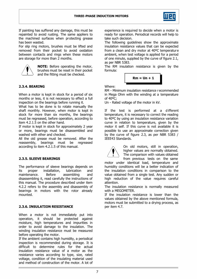
If painting has suffered any damage, this must be repainted to avoid rusting. The same appliers to the machined surfaces when protecting grease has been wasted. For slip ring motors, brushes must be lifted and removed from their pocket to avoid oxidation between contacts and rings when these motors are storage for more than 2 months.
NOTE: Before operating the motor, brushes must be reset in their pocket and the fitting must be checked.
2.3.4. BEARING When a motor is kept in stock for a period of six months or less, it is not necessary to effect a full inspection on the bearings before running it. What has to be done is to rotate manually the shaft monthly. However, when motor is kept in stock for more than six months, the bearings must be regreased, before operation, according to item 4.2.1.5 on the other hand. If motor is kept in stock for approximately 2 year or more, bearings must be disassembled and washed with ether and checked. All the old grease must be removed. After the reassembly, bearings must be regreased according to item 4.2.1.5 of this manual. 2.3.5. SLEEVE BEARINGS The performance of sleeve bearings depends on its proper installation, lubrication and maintenance. Before assembling and disassembling it, read carefully the instructions of this manual. The procedure described under item 4.2.2 refers to the assembly and disassembly of bearings in motors with the rotor already mounted. 2.3.6. INSULATION RESISTANCE When a motor is not immediately put into operation, it should be protected against moisture, high temperatures and impurities in order to avoid damage to the insulation. The winding insulation resistance must be measured before operating the motor. If the ambient contains high humidity, a periodical inspection is recommended during storage. It is difficult to determine rules for the actual insulation resistance value of a motor as the resistance varies according to type, size, rated voltage, condition of the insulating material used and method of construction of the motor. A lot of
experience is required to decide when a motor is ready for operation. Periodical records will help to take such decision. The following guidelines show the approximate insulation resistance values that can be expected from a clean and dry motor at 40ºC temperature ambient, when test voltage is applied for a period of one minute, supplied by the curve of figure 2.1, as per NBR 5383. The RM insulation resistance is given by the formula: Where: RM - Minimum insulation resistance r ecommended in Mega Ohm with the winding at a temperature of 40ºC; Un - Rated voltage of the motor in kV. If the test is performed at a d ifferent temperature, it is necessary to correct the reading to 40ºC by using an insulation resistance variation curve in relation to temperature, given by the motor it self. If this curve is not available it is possible to use an approximate correction given by the curve of figure 2.3, as per NBR 5383 / IEEE43 Standards.
On old motors, still in operation, higher values are normally obtained. The comparison with values obtained from previous tests on the same
motor under identical load, temperature and humidity conditions will be a better indication of the insulation conditions in comparison to the value obtained from a single test. Any sudden or high reduction of the value requires careful attention. The insulation resistance is normally measured with a MEGOMETER. If the insulation resistance is lower than the values obtained by the above mentioned formula, motors must be submitted to a drying process, as per item 4.7.
RM = Un + 1
Rm = Un + 1

8
THREE-PHASE INDUCTION MOTORS
Figure 2.3.
Insulation Resistance Value Insulation Level
2MΩ or smaller Bad < 50MΩ Dangerous
50...100MΩ Abnormal
100...500MΩ Good 500...1000MΩ Very good
> 1000MΩ Excellent Table 2.3a. - Reference limits for insulation resistant of electric motors.
Polarization Index Insulation Level
1 or smaller Bad
< 1,5 Dangerous 1,5 a 2,0 Abnormal
2,0 a 3,0 Good
3,0 a 4,0 Very Good > 4,0 Excellent
Table 2.3b. - Polarization index (ratio between 1 and 10 minutes).
Immediately after the measurement of the Isolation resistance, the windings must be grounded to prevent accident.

9
THREE-PHASE INDUCTION MOTORS
22..44.. HHAANNDDLLIINNGG Use only the existing eyebolts to lift the motor. Never lift the motor by the shaft. Check the motor weight. Lifting and lowering must be done gently in order to avoid damage to the bearings.
The eyebolts attached to bearing housing, heat exchanger, endbells, etc, should be used to handle these components only.
H LINE
Notes: 1) Lifting lugs on the frame are designed for
lifting machine only. Do not use for lifting coupled equipment such as pumps, compressors, gears or other equipment;
2) The chains or handles of hoisting must have on maximum angle of 30º with regard to vertical line:
3) Failure to observe these precautions may result in damage to the equipment, injury to personnel or both.
M LINE
Notes: 1) Do not the motor by the heat exchanger; 2) Lifting without heat exchanger; 3) If gravity center is not exactly in the
middle of the lifting lugs, use one of the ways as per item 3.
10
THREE-PHASE INDUCTION MOTORS
3. INSTALLATION Electric motors should be installed in locations of easy access for inspection and maintenance. If the surrounding atmosphere contains humid, corrosive or flammable substances or particles, it is essential to ensure an adequate degree of protection. The installation of motors in ambient where there are vapours, gases or dusts, flammable or combustible materials, subject to fire or explosion, should be done in accordance with ABNT NBR, NEC Art. 500 (National Electrical Code) and UL-674 (Underwriters Laboratories, Inc.) Standard. Under no circumstances, motors can be enclosed in boxes or covered with materials which may impede or reduce the free circulation of cooling air. Motors fitted with external cooling must be located at least 50mm from the ground to permit free air circulation. The air inlet and outlet should never be obstructed or reduced by conductors, pipes or other objects. The installation site should permit conditions of air renewal at a rate of 30m³ per minute for each 100kW motor output. 33..11.. MMEECCHHAANNIICCAALL AASSPPEECCTTSS 3.1.1. MOUNTING In order to ensure a smooth, vibration-free motor operation, in additional to a stable foundation, the motor must be precisely aligned and the components, which are to be mounted on the shaft end, must be suitable balanced. Notice: The relation between the natural frequency of the foundation and the speed frequency, the double speed frequency and the double line frequency must be as specified bellow after the installation of the machine set: - Foundation natural frequency of the 1st order
after installation of the machine set: ≥ +25% or ≤ -20% in relation to the above frequencies. - Foundation natural frequency of higher order
after installation of the machine set: ≥ +10% or ≤ -10% in relation to the above frequencies.
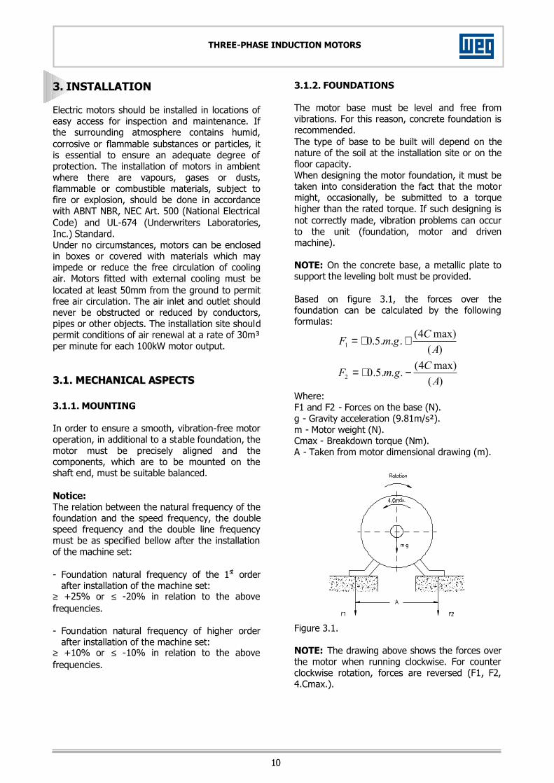
3.1.2. FOUNDATIONS The motor base must be level and free from vibrations. For this reason, concrete foundation is recommended. The type of base to be built will depend on the nature of the soil at the installation site or on the floor capacity. When designing the motor foundation, it must be taken into consideration the fact that the motor might, occasionally, be submitted to a torque higher than the rated torque. If such designing is not correctly made, vibration problems can occur to the unit (foundation, motor and driven machine). NOTE: On the concrete base, a metallic plate to support the leveling bolt must be provided. Based on figure 3.1, the forces over the foundation can be calculated by the following formulas:
)(max)4(...5.01 A
CgmF ++=
)(max)4(...5.02 A
CgmF −+=
Where: F1 and F2 - Forces on the base (N). g - Gravity acceleration (9.81m/s²). m - Motor weight (N). Cmax - Breakdown torque (Nm). A - Taken from motor dimensional drawing (m).
Figure 3.1. NOTE: The drawing above shows the forces over the motor when running clockwise. For counter clockwise rotation, forces are reversed (F1, F2, 4.Cmax.).
11
THREE-PHASE INDUCTION MOTORS
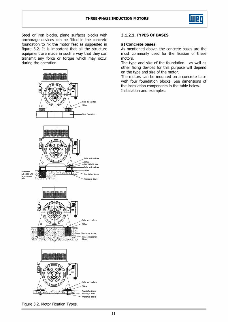
Steel or iron blocks, plane surfaces blocks with anchorage devices can be fitted in the concrete foundation to fix the motor feet as suggested in figure 3.2. It is important that all the structure equipment are made in such a way that they can transmit any force or torque which may occur during the operation. Figure 3.2. Motor Fixation Types.
3.1.2.1. TYPES OF BASES a) Concrete bases As mentioned above, the concrete bases are the most commonly used for the fixation of these motors. The type and size of the foundation - as well as other fixing devices for this purpose will depend on the type and size of the motor. The motors can be mounted on a concrete base with four foundation blocks. See dimensions of the installation components in the table below. Installation and examples:
12
THREE-PHASE INDUCTION MOTORS
Foundation block Fastening bolts (DIN 933)
Tapered pins (DIN 258) Hole diameter in the
motor feet Number Dimension Number Dimension Number Dimension
28 4 M24 4 M24 x 60 2 14 x 100
36 4 M30 4 M30 x 70 2 14 x 100
42 4 M36 4 M36 x 80 2 14 x 100
48 4 M42 4 M42 x 90 2 14 x 100
Mounting dimensions
Thread s t u v w
M26 and M30 50 450 220 265 315
M36 70 539 240 300 350
M42 70 600 270 355 400
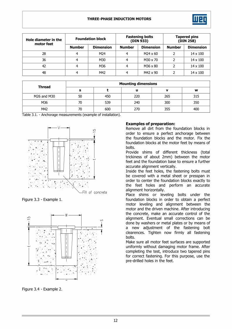
Table 3.1. - Anchorage measurements (example of installation). Figure 3.3 - Example 1. Figure 3.4 - Example 2.
Examples of preparation: Remove all dirt from the foundation blocks in order to ensure a perfect anchorage between the foundation blocks and the motor. Fix the foundation blocks at the motor feet by means of bolts. Provide shims of different thickness (total trickiness of about 2mm) between the motor feet and the foundation base to ensure a further accurate alignment vertically. Inside the feet holes, the fastening bolts must be covered with a metal sheet or presspan in order to center the foundation blocks exactly to the feet holes and perform an accurate alignment horizontally. Place shims or leveling bolts under the foundation blocks in order to obtain a perfect motor leveling and alignment between the motor and the driven machine. After introducing the concrete, make an accurate control of the alignment. Eventual small corrections can be done by washers or metal plates or by means of a new adjustment of the fastening bolt clearences. Tighten now firmly all fastening bolts. Make sure all motor feet surfaces are supported uniformly without damaging motor frame. After completing the test, introduce two tapered pins for correct fastening. For this purpose, use the pre-drilled holes in the feet.

13
THREE-PHASE INDUCTION MOTORS
b) Slide rails When drive system is done by pulleys, the motor should be mounted on slide rails and the lower part of the belt must be pulling. The rail that stays near the drive pulley is positioned in such a manner that the adjusting bolt be between the motor and the driven machine. The other rail must be positioned with the bolt in the opposite position, as shown in figure 3.5. The motor is bolted to the rails and set on the base. The drive pulley is then aligned in such a way that its center be in the same level of the driven pulley center. Motor and driven machine shafts must be in a parallel position. The belt should not be excessively stretched, see figure 3.12. After the alignment, rails are to be fixed. Figure 3.5. c) Metallic bases The metallic bases must have a flat surface under motor feet in order to avoid frame deformation. The bearing housing surface should be so determined that under the feet of the motor one can place shim plates of approximately 2mm thickness. Motor should not be removed from their common metallic bases for alignment, the metallic bases should be leveled on the actual foundation. When a metallic base is used to adjust the height of the motor shaft end with the machine shaft end, it should be leveled on the concrete base. After the base has been leveled, foundation studs tightened, and the coupling checked, the metal base and the studs are then cemented.
3.1.3. ALIGNMENT/LEVELING The electric motor must be accurately aligned with the driven machine, particularly in cases of direct coupling. An incorrect alignment can cause bearing defects, vibrations and even shaft breaking. The best way to ensure correct alignment is to use dial indicator placed on each coupling half, one reading radially and the other axially. In this way, simultaneous readings can be informed and one can check any parallel (figure 3.6a) or concentricity deviations (figure 3.6b) by rotating the shaft. The dial indicator should not exceed 0.05mm. If the operator is sufficiently skilled, he can obtain alignment with clearance gauge and a steel ruler, providing that the couplings be perfect and centered (figure 3.6c). A measurement at 4 different points of the circumference should not give a reading difference larger than 0.03mm. Figure 3.6a – Parallelism deflection. Figure 3.6b – Concentricity deflection. On the alignment/leveling it is important to take into consideration the effect of the temperature over the motor and driven machine. The different expansion levels of the coupled machines can modify the alignment/leveling during motor operation. After the set (motor and base) is perfectly aligned either at cold or at hot, motor must be bolted, as shown in figure 3.7. There are instruments which use visible laser ray added by specific computer programs that can perform and ensure high precision alignment.
14
THREE-PHASE INDUCTION MOTORS
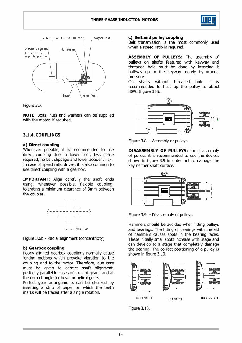
Figure 3.7. NOTE: Bolts, nuts and washers can be supplied with the motor, if required. 3.1.4. COUPLINGS a) Direct coupling Whenever possible, it is recommended to use direct coupling due to lower cost, less space required, no belt slippage and lower accident risk. In case of speed ratio drives, it is also common to use direct coupling with a gearbox. IMPORTANT: Align carefully the shaft ends using, whenever possible, flexible coupling, tolerating a minimum clearance of 3mm between the couples. Figure 3.6b - Radial alignment (concentricity). b) Gearbox coupling Poorly aligned gearbox couplings normally cause jerking motions which provoke vibration to the coupling and to the motor. Therefore, due care must be given to correct shaft alignment, perfectly parallel in cases of straight gears, and at the correct angle for bevel or helical gears. Perfect gear arrangements can be checked by inserting a strip of paper on which the teeth marks will be traced after a single rotation.
c) Belt and pulley coupling Belt transmission is the most commonly used when a speed ratio is required. ASSEMBLY OF PULLEYS: The assembly of pulleys on shafts featured with keyway and threaded hole must be done by inserting it halfway up to the keyway merely by manual pressure. On shafts without threaded hole it is recommended to heat up the pulley to about 80ºC (figure 3.8). Figure 3.8. - Assembly or pulleys. DISASSEMBLY OF PULLEYS: for disassembly of pulleys it is recommended to use the devices shown in figure 3.9 in order not to damage the key neither shaft surface. Figure 3.9. - Disassembly of pulleys. Hammers should be avoided when fitting pulleys and bearings. The fitting of bearings with the aid of hammers causes spots in the bearing races. These initially small spots increase with usage and can develop to a stage that completely damage the bearing. The correct positioning of a pulley is shown in figure 3.10. Figure 3.10.
INCORRECT CORRECT INCORRECT

15
THREE-PHASE INDUCTION MOTORS
RUNNING: Avoid unnecessary thrusts on the bearings by ensuring that the shafts are parallel and the pulleys perfectly aligned (figure 3.11). Laterally misaligned pulleys, when running, transmit alternating knocks to the rotor and can damage the bearing housing. Belt slippage can be avoided by applying a resin type material such as rosin. Figure 3.11. - Correct pulley alignment. Belt tension is only required to avoid slippage during operation (figure 3.12). Figure 3.12 - Belt tension. NOTE: A belt with excessive tension increases the force on the shaft end causing vibrations and fatigue leading to a possible shaft rupture. Excessively small pulleys should be avoided; these cause shaft flexion as belt traction increases with the decrease of pulley size. When specific pulleys are required, contact Weg Máquinas in order to insure a correct designing.
Due to the existing tensions on the belts, there is a reaction acting as radial load over the motor shaft end. The data to calculate such reaction (radial force) are: - Output transmitted [kW] (P); - Motor speed [rpm] (RPM); - Diameter of driven pulley [mm] (DPMV); - Diameter of driven pulley [mm] (DPMT); - Distance between centers [mm] (I); - Friction coefficient [-] (MI) - (normally 0.5); - Slip coefficient [-] (K); - Belt contact angle on smaller pulley [RAD] (alfa); - FR: Radial force acting over the shaft end [N] (FR).
NOTE: Always use pulleys duly machined and balance with concentric and equidistant holes. Avoid, in all cases, oversized keys as these can cause unbalancing. In case these instructions are not followed accordingly, vibration levels will occur. 3.1.4.1. COUPLING ARRANGEMENT FOR SLEEVE BEARING MOTORS - AXIAL CLEARANCE Motors fitted with sleeve bearings should be directly coupled to the driven machine or even using a gearbox. Pulley/belt coupling is not recommended. These sleeve bearing motors have three identification marks on the shaft end. The central mark (red painted) indicated the magnetic center; the other two indicate the limits for the rotor axial displacement. When coupling the motor, the following aspects must be considered: - Bearing axial clearance which is shown on the
chart below for each bearing size. - Axial displacement of the driven machine, if
any. - Maximum axial clearance allowed by the
coupling.
( )( )
[ ] ( )[ ]2
121.1(125,18836
111.1
1
2 ALFACOSxALFACOSxKx
DPMTxRPMNFR
MIxALFAMIxALFAxK
DPMTDPMVALFA
++−=
−+
=
−
−=
χ
εε
π

16
THREE-PHASE INDUCTION MOTORS
Clearances applied to sleeve bearings for motor supplied by Weg Máquinas
Bearing size Total axial clearance in mm
9 3 + 3 = 6
11 4 + 4 = 8
14 5 + 5 = 10
18 7,5 + 7,5 = 15
22 12 + 12 = 24
28 12 + 12 = 24
Table 3.3. The motor must be coupled in such a way that the arrow attached to the bearing frame be positioned exactly on the central mark (red painted) while motor is in operation. During motor starting or even under operation, rotor should move freely between the two external lots if the driven machine creates any axial force on the motor shaft. Under no circumstance, motor can operate continuously with axial force on the bearing. Sleeve bearings normally used by Weg Máquinas are not designed to withstand axial forces continuously. The figure 3.14 shows part of the drive end bearing highlighting a basic configuration of the shaft/bearing set as well as axial clearances.
Figure 3.14. The figure 3.15 shows part of the bearing frame where the arrow indicates the magnetic center and the three marks on the shaft.
Figure 3.15. 33..22.. EELLEECCTTRRIICCAALL AASSPPEECCTTSS 3.2.1. SUPPLY SYSTEM Proper electric power supply is very important. All the wires and protection system must ensure an excellent quality of electric power supply on the motor terminals within the following parameters: - Voltage: It can fluctuate within a range of
more or less 10% in relation to rated value. - Frequency: It can fluctuate within a range of -
3 and +5% in relation to rated value. 3.2.2. CONNECTION In order to connect the supply conductors, remove the covers of the rotor and stator terminal boxes (if any). Cut the sealing rings (standard motors are not supplied with cable glands) according to the diameter to be used. Insert the conductors into the rings. Cut the supply conductors to desired length, disbarkt the ends and assemble the terminals on them. Connect the metallic covering of the conductors (if any) to the common grounding. Cut the grounding terminal to size and connect it to the existing connector in the terminal box and/or frame. Fasten all connections firmly. NOTE: Do not use, for terminal fastening, eel washers or other material which do not have excellent electric conductivity characteristics.

17
THREE-PHASE INDUCTION MOTORS
It is recommended to apply a grease protection on all connections before performing the connection. Insert all sealing rings into the respective grooves. Screw the terminal box cover carefully, ensuring that the sealing rings are correctly introduced. 3.2.3. GENERAL CONNECTION DIAGRAMS We are presenting below orientative connection diagrams for squirrel cage and slip ring induction motors as well as motors supplied with lighting arrestors and surge capacitors. Figure 3.16. - General connection diagram for squirrel cage motors. Figure 3.17. - General connection diagram for slip ring motors.
Figure 3.18. - General connection diagram for motors supplied with lightning arrestors and capacitors. 3.2.4. CONNECTION DIAGRAMS The following connection diagrams show the number of terminals and how they have to be connected. There is a nameplate on the motor indicating the connection diagram code that must be used. GENERAL IDENTIFICATION OF TERMINALS, STATOR, ROTOR AND ACCESSORIES 01 to 12 = Stator. 13 to 15 = Rotor. 16 to 19 = Space heater. 20 to 27 = RTD (PT100) in winding. 36 to 43 = Thermistors (PTC) in winding. 52 to 59 = Thermostats in winding (Klixon, Compela). 68 to 71 = RTD's in the bearings. 72 to 75 = Thermistors in the bearings. 76 to 79 = Thermostats. 80 to 82 = Thermometer. 92 to 93 = Brakes. 94 to 99 = Current transformers.

18
THREE-PHASE INDUCTION MOTORS
STATOR CONNECTION DIAGRAMS 3 LEADS 6 LEADS 6 LEADS - DAHLANDER 9000
9001
㥀 Y
9002
㥀
LOWER SPEED
9003 YY
HIGHER SPEED
9004 Y
LOWER SPEED
9005
YY
LOWER SPEED
9006
㥀
HIGHER SPEED 9 LEADS 12 LEADS 9007
㥀㥀
9008
㥀
9009
YY
9010
Y
9011
㥀㥀
9012
㥀
9013
YY
9014
Y
12 LEADS - (part winding) 9015
FOR STARTING IN Y
9016
FOR STARTING IN 㥀
9017
ONLY FOR STARTING
IN Y
9018 FOR RATED SPEED
DIRECTION OF ROTATION The direction of rotation of the engine is described in the nameplate The connection of the stator terminals 1, 2 and 3 respectively in phases R, S and Tdetermines the clock-wise direction of rotation viewed on the drive-end side (main shaft-end), according to IEC60034 Standard. To invert the direction of the rotation must be inverted the connection of two phases. The motors with only one direction of rotation possess unidirectional fan and must only operate in the specified direction. If is really necessary to invert the direction of the rotation, WEG must be consulted.

19
THREE-PHASE INDUCTION MOTORS
STATOR CONNECTION DIAGRAM (SLIP-RING MOTORS)
ROTOR
9020
9019
ACCESSORIES CONNECTION DIAGRAMS
THERMOSTATS
9029 IN WINDING 1 PER PHASE
9030 IN WINDING
1 PER PHASE IN SERIES
9031 IN WINDING 2 PER PHASE
ALARM TRIPPING
9032 IN WINDING
2 PER PHASE IN SERIES
ALARM TRIPPING
9036 IN THE BEARINGS 1 PER BEARING
FRONT REAR
THERMISTORS 9025
IN WINDING 1 PER PHASE
9026 IN WINDING
1 PER PHASE IN SERIES
9027 IN WINDING 2 PER PHASE
ALARM TRIPPING
9028 IN WINDING
2 PER PHASE IN SERIES
ALARM TRIPPING
9035 IN THE BEARINGS 1 PER BEARING
FRONT REAR
TERMOSENSORS – RDT (PT-100) 9021
IN WINDING 1 PER PHASE
9022 IN WINDING
1 PER PHASE WITH 3 WIRES
9023 IN WINDING 2 PER PHASE
ALARM TRIPPING
9024 IN WINDING
2 PER PHASE WITH 3 WIRES
ALARM TRIPPING
9033 IN THE BEARINGS 1 PER BEARING
FRONT REAR
9034 IN THE BEARINGS
1 PER BEARING WITH 3 WIRES
FRONT REAR

20
THREE-PHASE INDUCTION MOTORS
SPACE HEATER (single voltage) SPACE HEATER (double voltage) 9038
9039 WITH THERMOSTAT
9410 LOWER VOLTAGE HIGHER VOLTAGE
THERMOMETER (front bearing) THERMOMETER (rear bearing) 9037
9037
SUPPLEMENTARY ACCESSORIES In motors with more than 1 bearing for support, the sensor of temperature used in the extra bearing is identified with the corresponding number to the first bearing preceded of the number 1 (for 1 extra bearing) or 2 (for 2 extra bearings) Example: Motor with rear support composed of 2 bearings - 1 PT100 with 3 wires for bearing. The first bearing is identified with numeration 70 - 70 - 71 and the second bearing with numeration 170 - 170 - 171. The same rule described above applies also for extra sensors in the stator or extra thermometers in the bearings.

21
THREE-PHASE INDUCTION MOTORS
3.2.5. ELECTRICAL MOTORS STARTING 3.2.5.1. STARTING – SQUIRREL-CAGE MOTOR Whenever possible, three-phase squirrel cage motors should be started directly at full voltage through a contactor. DOL is the easiest method of starting; only feasible, however, when the starting current does not affect the power supply. Normally, the starting current of induction motors is six to seven times the rated current. Note that high starting current can cause supply disturbances to other consumers due to voltage drops in the main power supply. This situation can be corrected with one of the following options: a) The power supply rated current is so high that
the starting current is not proportionally high; b) Motor is started under no-load conditions with
a short starting cycle and, as a consequence, a low starting current with a transient voltage drop tolerable to other consumers;
c) When duly authorized by the regional Energy Company (utility).
In the cases where the starting current of the motor is high, the following harmful consequences can occur: a) High voltage droop in the grid of the feeding
system. In function of this, it provokes interference in equipments installed in this system;
b) The protection system (lead, contactors) must be over specified, causing a high cost;
c) The imposition of the electrical energy companies who limit the voltage droop.
If direct starting is not feasible, either due to restrictions imposed by the utility or due to the installation itself, reduced voltage indirect starting methods can be used in order to reduce the starting current. These indirect starting methods (reduced voltage) are: - Wye-delta switch; - Series-parallel switch; - Compensating Switch or self-transformer; - Static starting switch or soft-start; - Frequency Inverter.
3.2.5.2. FREQUENCY OF DIRECT STARTINGS Due to high starting current value on induction motor, the time required to accelerate high inertia loads results in sudden motor temperature rise. If interval between successive starts is significantly reduced, this will result in excessive winding temperature causing damage or reduce their life time. NBR 7094 establishes a minimum starting system electric motors must be suitable to withstand: a) Two successive starts, where the fir st is made
with motor still cold, that is, with winding at ambient temperature and the second r ight after that. However, only when motor has decelerated until rest;
b) One start with motor at hot, that is, with winding at service duty temperature.
The first condition simulates a case where the first start is affected. For example, due to protection switching-off, then allowing a second try right after that one. The second condition simulates a case of a motor accidental switching-off at normal operation. For example, due to lack of power supply, then allowing a second try as soon as the power supply returns. 3.2.5.3. LOCKED ROTOR CURRENT (Ip/In) According to NBR7094 Standard, the value of Ip/In indicated on the motor nameplate is the relation between the locked rotor current and the motor rated current. 3.2.5.4. STARTING OF SLIP RING MOTORS WITH RHEOSTAT For starting of slip ring motors an external rheostat is connected to the rotor by means of a set of brushes and slip rings. The extra rotor resistance is held in the c ircuit during the starting to reduce the starting current and increase torque. Furthermore, it is possible to regulate the external resistance so as to have a starting torque equal to, or close to the motor breakdown torque. NOTE: Every time customers intend to use other than direct starting, inform WEG Máquinas in advance so we can analyze the starting torques required by the load.
22
THREE-PHASE INDUCTION MOTORS
3.2.6. MOTOR PROTECTION Motors have, in principle, two types of protection: protection against overload/locked rotor, and short circuits. Motors in continuous use should be protected from overloading by means of a device incorporated into the motor, or by independent device, usually a fixed or adjustable thermal relay equal or inferior to the value derived from multiplying the rated power supply current at full load by: - 1.25 for motors with a service factor equal or
superior to 1.15 or; - 1.15 for motors with service factor equal to
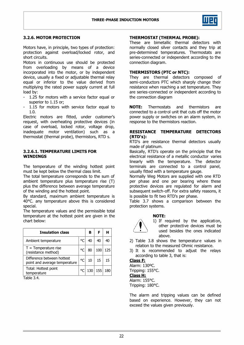
1.0. Electric motors are fitted, under customer’s request, with overheating protective devices (in case of overload, locked rotor, voltage drop, inadequate motor ventilation) such as a thermostat (thermal probe), thermistors, RTD s. 3.2.6.1. TEMPERATURE LIMITS FOR WINDINGS The temperature of the winding hottest point must be kept below the thermal class limit. The total temperature corresponds to the sum of ambient temperature plus temperature rise (T) plus the difference between average temperature of the winding and the hottest point. By standard, maximum ambient temperature is 40°C. any temperature above this is considered special. The temperature values and the permissible total temperature at the hottest point are given in the chart below:
Insulation class B F H
Ambient temperature °C 40 40 40 T = Temperature rise (resistance method) °C 80 100 125
Difference between hottest point and average temperature °C 10 15 15
Total: Hottest point temperature °C 130 155 180
Table 3.4.
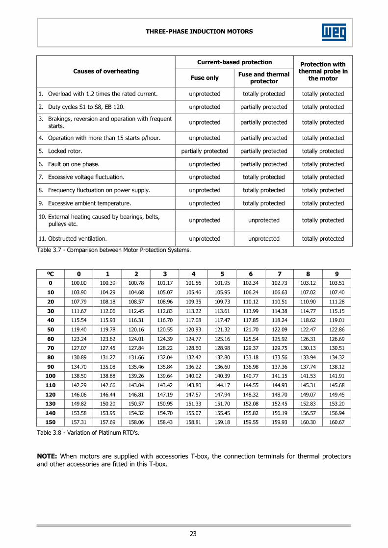
THERMOSTAT (THERMAL PROBE): These are bimetallic thermal detectors with normally closed silver contacts and they trip at pre-determined temperatures. Thermostats are series-connected or independent according to the connection diagram. THERMISTORS (PTC or NTC): They are thermal detectors composed of semi-conductors PTC which sharply change their resistance when reaching a set temperature. They are series-connected or independent according to the connection diagram NOTE: Thermostats and thermistors are connected to a control unit that cuts off the motor power supply or switches on an alarm system, in response to the thermistors reaction. RESISTANCE TEMPERATURE DETECTORS (RTD's): RTD's are resistance thermal detectors usually made of platinum. Basically, RTD's operate on the principle that the electrical resistance of a metallic conductor varies linearly with the temperature. The detector terminals are connected to a control panel, usually fitted with a temperature gauge. Normally Weg Motors are supplied with one RTD per phase and one per bearing where these protective devices are regulated for alarm and subsequent switch-off. For extra safety reasons, it is possible to fit two RTD's per phase. Table 3.7 shows a comparison between the protection systems.
NOTE: 1) If required by the application,
other protective devices must be used besides the ones indicated above.
2) Table 3.8 shows the temperature values in relation to the measured Ohmic resistance.
3) It is recommended to adjust the relays according to table 3, that is:
Class F: Alarm: 130ºC. Tripping: 155°C. Class H: Alarm: 155°C. Tripping: 180°C. The alarm and tripping values can be defined based on experience. However, they can not exceed the values given previously.
23
THREE-PHASE INDUCTION MOTORS
Current-based protection Causes of overheating
Fuse only Fuse and thermal protector
Protection with thermal probe in
the motor
1. Overload with 1.2 times the rated current. unprotected totally protected totally protected
2. Duty cycles S1 to S8, EB 120. unprotected partially protected totally protected
3. Brakings, reversion and operation with frequent starts.
unprotected partially protected totally protected
4. Operation with more than 15 starts p/hour. unprotected partially protected totally protected
5. Locked rotor. partially protected partially protected totally protected
6. Fault on one phase. unprotected partially protected totally protected
7. Excessive voltage fluctuation. unprotected totally protected totally protected
8. Frequency fluctuation on power supply. unprotected totally protected totally protected
9. Excessive ambient temperature. unprotected totally protected totally protected
10. External heating caused by bearings, belts, pulleys etc.
unprotected unprotected totally protected
11. Obstructed ventilation. unprotected unprotected totally protected
Table 3.7 - Comparison between Motor Protection Systems.
ºC 0 1 2 3 4 5 6 7 8 9 0 100.00 100.39 100.78 101.17 101.56 101.95 102.34 102.73 103.12 103.51
10 103.90 104.29 104.68 105.07 105.46 105.95 106.24 106.63 107.02 107.40
20 107.79 108.18 108.57 108.96 109.35 109.73 110.12 110.51 110.90 111.28
30 111.67 112.06 112.45 112.83 113.22 113.61 113.99 114.38 114.77 115.15
40 115.54 115.93 116.31 116.70 117.08 117.47 117.85 118.24 118.62 119.01
50 119.40 119.78 120.16 120.55 120.93 121.32 121.70 122.09 122.47 122.86
60 123.24 123.62 124.01 124.39 124.77 125.16 125.54 125.92 126.31 126.69
70 127.07 127.45 127.84 128.22 128.60 128.98 129.37 129.75 130.13 130.51
80 130.89 131.27 131.66 132.04 132.42 132.80 133.18 133.56 133.94 134.32
90 134.70 135.08 135.46 135.84 136.22 136.60 136.98 137.36 137.74 138.12
100 138.50 138.88 139.26 139.64 140.02 140.39 140.77 141.15 141.53 141.91
110 142.29 142.66 143.04 143.42 143.80 144.17 144.55 144.93 145.31 145.68
120 146.06 146.44 146.81 147.19 147.57 147.94 148.32 148.70 149.07 149.45
130 149.82 150.20 150.57 150.95 151.33 151.70 152.08 152.45 152.83 153.20
140 153.58 153.95 154.32 154.70 155.07 155.45 155.82 156.19 156.57 156.94
150 157.31 157.69 158.06 158.43 158.81 159.18 159.55 159.93 160.30 160.67
Table 3.8 - Variation of Platinum RTD's. NOTE: When motors are supplied with accessories T-box, the connection terminals for thermal protectors and other accessories are fitted in this T-box.

24
THREE-PHASE INDUCTION MOTORS
3.2.6.2. SPACE HEATERS When motors are fitted with space heaters to avoid water condensation during long periods o standstill, the space heaters must be connected so that they are energized immediately after the motor is switched-off and are energized immediately after the motor is switched-on. A dimensional drawing and a specific nameplate existing on the motor indicate the supply voltage and the characteristics of the space heaters installed. 3.2.6.3. VIBRATION LIMITS WEG motors and generators Are factory balanced and comply with vibration limits established by IEC34-14, NEMA MG1 - Part 7 and NBR 11390 Standards (except when the purchasing agreement specifies different values). Vibration measurements are performed on the non-drive and drive end bearings, vertically, horizontally and axially. When a customer supplies the coupling half sleeve to WEG, the motor in question is balanced with this half sleeve mounted to the shaft. When this is not the case, based on the above standards motor is balanced with half key (that is, the key way is fulfilled with a piece of metal of identical width, thickness and height of the keyway). The maximum allowable vibration levels recommended by WEG for motors in operation are given on the table below. These values are generic and serve as a guideline. Specific application conditions must be taken into consideration:
Vibration Levels (mm/s RMS) Rated speed
(rpm) Frame < 355355 to
630 > 630
Alarm 4.5 4.5 5.5 600 ≤ n ≤ 1800
Tripping 7.0 7.0 8.0
Alarm 3.5 4.5 5.5 1800 < n ≤ 3600
Tripping 5.5 6.5 7.5 Table 3.5. Vibration causes most frequently found on the field are: - Misalignment between motor and driven
machine;
- Incorrect motor fastening to the base, with “loose shims” underneath one or more motor feet and studs incorrectly fastened;
- Improper base, or not firmly built; - External vibrations caused by other equipment. Operate the motor with vibration values above those described above can damage its lifetime and/or its performance. 3.2.6.4. VIBRATION LIMITS FOR SLEEVE BEARINGS In motors equipped or with forecast for installation of proximity sensor (normally used in sleeve bearing) the shaft surfaces are prepared with special finishing in the adjacent areas of the bearings, so as to ensure the correct shaf t vibration measurement. The shaft vibration in these motors is measured and must comply with IEC 34-14 and NEMA MG 1 Standards. The alarm and tripping values of the table 3.6 represent values of permissible shaft vibration for coupled electric machines as norm ISO7919-3. They are generic values and serve as a guideline, where specific application conditions must be taken into consideration, mainly diametric clearance between shaft and bearing.
Shaft vibration (㯀m peak to peak) Rated speed (rpm) Frame
280 and 315
355 to
450 > 450
Alarm 110 130 150 1800
Tripping 140 160 190
Alarm 85 100 120 3600
Tripping 100 120 150 Table 3.6. Operate the motor with shaft vibration values close to alarm and tripping values can damage bearing liners.
The main reasons to cause increase of vibration are: - Unbalance coupling problems and others that
can affect the machine; - Shaft manufacturing problems, which are
minimized during the manufacturing; - Residual voltage or magnetism on the shaft
surface where measurement is made; - Scratches, knocks or vibrations when fini shing
the shaft where measurement is made.

25
THREE-PHASE INDUCTION MOTORS
33..33.. CCOOMMMMIISSSSIIOONNIINNGG 3.3.1. PRELIMINARY INSPECTION Before starting a motor for the first time, or after long period of standstill, check the following items: 1) Is the motor clean? Were all packing
materials and cleaning materials removed? 2) Make sure the supply voltage and frequency
correspond to those indicated on the nameplate.
3) Ascertain that the endbell and bearing-housing fastening bolts are firmly tightened.
4) Make sure the motor is correctly aligned (as per item 3.1.2).
5) Are the bearings correctly lubricated (as per item 4.2).
6) Are the rotor terminals connected? (Only for slip ring motors).
7) Are the thermal protector conductors, the rounding terminal and the space heaters connected?
8) Is the insulation resistance of the rotor and stator according to the prescribed value ? (as per item 2.3.3).
9) Were all objects such as tools, measuring instruments and alignment devices removed from the area of the motor?
10) Are the brush-holders in order? Are the brushes making contact? (see item 4.6).
11) Are all motor fixing bolts duly tightened? 12) When the motor is started at no load, does it
rotate freely without abnormal noise? Is the direction of rotation correct? (To reverse the rotation, invert any of two terminal leads of the power supply).
13) Is the motor ventilation OK? Note the direction of rotation of unidirectional motors.
NOTES: 1) The gap between brush holder and Slip ring
surfaces should be between 2mm to 4mm. 2) Brush pressure on the slip ring should be in
accordance with the specified value, and the brush incidence to the contact surface should be perpendicular.
3) If the load (operation rated current) applied to the motor are not in accordance with the rated characteristics of such motor (above or below), the brushes specification must be analyzed in relation to the actual load requirements. Check data given in item 4.6.
4) Before changing rotation direction of two-pole motors, contact Weg Máquinas for analysis.
5) The "H" line motors with special noise level are built with unidirectional fan (all RPM´s). To reverse rotation direction, contact Weg Máquinas in order to analyze the fan.
6) The "Master" line motors are also built with unidirectional fans. So if rotation direction has to be reversed, contact Weg Máquinas in order to analyze the fan.
WARNING: The non observation of the items described above can lead to serious problems to motor performance, causing excessive wear to brushes and slip rings (for wound rotor motors), overheating and possible damage to motor windings. These problems are not covered under the warranty terms included in this manual. 3.3.2. START-UP THREE-PHASE SQUIRREL CAGE ROTOR MOTOR After careful examination on the motor, follow the normal sequence of starting operation listed above. THREE-PHASE SLIP RING MOTORS - The starting method must follow the
manufacturer instructions for starting methods.
- On motors with permanent contact bru shes, the starting rheostat remains in the "run" position while the motor is running.
- Special speed control rheostat designed for permanent connection to resistance contacts within a given range of settings are an exception to the above.
- Brushes must be correctly set against the slip ring.
- In motor with adjustable brush-holder system, after complete motor acceleration, make sure that the brush lifting system has worked.

26
THREE-PHASE INDUCTION MOTORS
*** WARNING *** The motor connection boxes equipped capacitors do not have to be opened before the discharge time: Time of discharge of the capacitors: 5 minutes after the disconnection of the motor.
3.3.3. OPERATION Run the motor coupled to the load for a period of at least one hour to check if abnormal noises or sign of overheating occur. If there will be excessive vibrations in the unit between the initial operation condition and the condition after thermal stability, alignment and leveling must be rechecked. Compare the line current drawn with the value shown on the nameplate. Under continuous duty without load fluctuation, this should not exceed the rated current times the service factor, also shown on the nameplate. All measuring instruments and devices should be continuously checked in order to correct any abnormal operation, if required. On slip-ring motors, the real load condition of the motor in duty, must be investigated, and if necessary, specify again the set of brushes. In case of doubt consult WEG Máquinas. 3.3.4. SHUTDOWN PROCEDURE Before proceed any tasks on the motor, it is extremely important to observe the following: to touch any moving part on a running motor, even switched-off, is a danger to life. a) THREE-PHASE SQUIRREL CAGE MOTORS:
It suffices to open stator circuit switch, and with the motor stopped, reset the auto-transformer, if any, to the "start" position;
b) THREE-PHASE SLIP RING MOTORS: Open
the stator circuit switch. When the motor is stopped, reset the rheostat to the "start" position.
33..44.. AACCOOUUSSTTIICCAALL PPRROOPPEERRTTIIEESS Day by day, electrical motors are increasingly used in offices and homes. Under these circumstances, it is essential that motors operate silently and safe without contributing to ambient discomfort. The solution lies in the ever closer collaboration of the user and the motor manufacturer. The proper planning of home, office and factory acoustics requires knowledge of the sources of motor noises and how they affect the ambient noise level wherever motors are located. The following parts of a motor can generate noise within the audio-frequency range: 1) Cooling system. 2) Brushes. 3) Bearings. 4) Magnetic circuit. The part of the motor mainly responsible as noise source depends on its size, speed, degree of mechanical protection (casing) and of the driven machine design. Cooling system noise is airborne and usually affects only the noise level in the ambient where motor is installed. How ever, it is a different matter if the noise source is in the bearings or in the magnetic circuit. In this case, the noise is due to mechanical vibration of the part itself, or of the entire motor, and the sound is spreaded through the foundation, walls or ducts. This type of sound propagation, via structural components of an installation, can be reduced by installing the motor on suitable designed vibration dampers. It is important to note that improper dampers can even increase vibration. 33..55.. MMOOTTOORR UUSSEEDD OONN HHAAZZAARRDDOOUUSS AARREEAA EEXXPPLLOOSSIIVVEE GGAASS AATTMMOOSSPPHHEERREESS Motors designed for hazardous areas are fitted with additional safety features which are defined in specific standards for each type of hazardous location, based on its classification. The general requirements for electrical apparatus for hazardous locations are described in the following Brazilian and foreign standards, respectively: NBR 9815 = Electrical apparatus for explosive gas atmospheres. General requirements (specifications) IEC 79-0 = Electrical apparatus for explosive gas atmospheres. EN 50014 = Electrical apparatus for potentially explosive atmosphere. General requirements

27
THREE-PHASE INDUCTION MOTORS
3.5.1. GENERAL CARE WITH HAZARDOUS LOCATION MOTORS Before installing, operating or carrying out maintenance services on electric motors used on hazardous locations, care must be taken on the following: - The standards listed below, applied to each
case, must be studied and understood; - All requirements included in the applicable
standards must be understood accordingly. Exe – Increased Safety: IEC 79-7 / NBR 9883 / EN 50019. Exp. – Pressurized: IEC 79-2 / NBR 5420. Exn – Non sparking: IEC 7915. 3.5.2. ADDITIONAL CARE RECOMMENDED FOR HAZARDOUS LOCATION MOTORS - Before carrying out maintenance services,
inspections or repairs on the motor, make sure it is de-energized and completely stopped;
- All motor protections must be correctly installed and duly adjusted before starting the operation;
- Make sure motors are properly grounded; - Connection terminals must be properly
connected so as to avoid poor contacts which can result in overheating or sparking.
NOTE: All other recommendations referring to storage, handling, installation and maintenance included in this manual and applied to the motor in question must also
be followed accordingly.

28
THREE-PHASE INDUCTION MOTORS
4. MAINTENANCE A well-programmed maintenance of electric motors can be summed up as a periodical inspection of insulation levels, temperature rise (winding and bearings), wears, bearing lubrication and useful life, and occasional checking of fan air flow, vibration levels, brushes and slip rings wears. In case one of the above items are not followed accordingly, you might have unexpected stops of the equipment. Inspection cycles depend on the type of the motor and conditions under which it operates. Frame must be kept clean, free of dust, dirt or oil in order to make the cooling process easier. Transportation care: On any transportation, motors fitted with roller or ball bearings must have their shaft locked in order to avoid bearing damage. To lock the shaft use the shaft locking device shipped together with the motor. See item 2.2. 44..11.. CCLLEEAANNLLIINNEESSSS Motors should be kept clean, free of dust, dirt and oil. Soft brushes or clean cotton rags should be used to clean the motors. A jet of compressed air should be used to remove non-abrasive dust from the fan cover and any accumulated grime from the fan and cooling fins. The heat exchanger tubes (if any) must be kept clean and free of any obstructing object to facilitate the air circulation. For the cleanliness of the tubes, a stick with a round brush at the ends can be used which, inserted in such tubes, removed all accumulated dirt.
NOTE: To perform such cleanliness, remove the ND end bell of the heat exchanger and insert the brush into the tubes.
In order to effect this cleanliness, a stick can be used which, inserted into the tubes, remove all the accumulated dust. If motor is fitted with air-water heat exchanger, a periodical cleanliness is inside the radiator tube is required to remove any dirt condensation. On slip ring motors, brushes and brush-holders should never be cleaned with compressed air, but with vacuum cleaner or any cotton rag soaked in a suitable solvent (see item 4.5).
Oil or damp impregnated impurities can be removed with rags soaked in a suitable solvent. Terminal boxes of IP54 protection motors should also be cleaned; their terminals should be free of oxidation, in perfect mechanical condition, and all unused space dust-free. For aggressive environment, IP(W)55 protection motors are recommended. 4.1.1. PARTIAL CLEANLINESS - Drain the condensed water. - Clean the inside of the terminal boxes. - Make a visual inspection of the winding
insulation. - Clean the slip rings (see 4.4 and 4.5). - Check the condition of the brushes. - Clean the heat exchanger. 4.1.2. COMPLETE CLEANLINESS - Clean the dirty windings with a soft brush. - Grease, oil and other impurities which adhered
on the winding can be removed with a rag soaked in alcohol. Dry the windings with a jet of compressed air.
- A jet of compressed air should be used to clean the bearings and the air ducts in the stator and rotor cores.
- Drain the condensed water and clean the inside of the terminal boxes as well as the slip rings.
- Measure the insulation resistance (see table 2.3a).
- Clean the brushes/brush holders according to items 4.5.
- Clean the heat exchanger accordingly.
NOTE: When motor is fitted with air inlet and/or air outlet filters, these should be cleaned with a jet of compressed air.
If the dust is difficult to be removed with a jet of compressed air, then they should be washed in cold water with neutral detergent. After that, dry them in horizontal position.
29
THREE-PHASE INDUCTION MOTORS
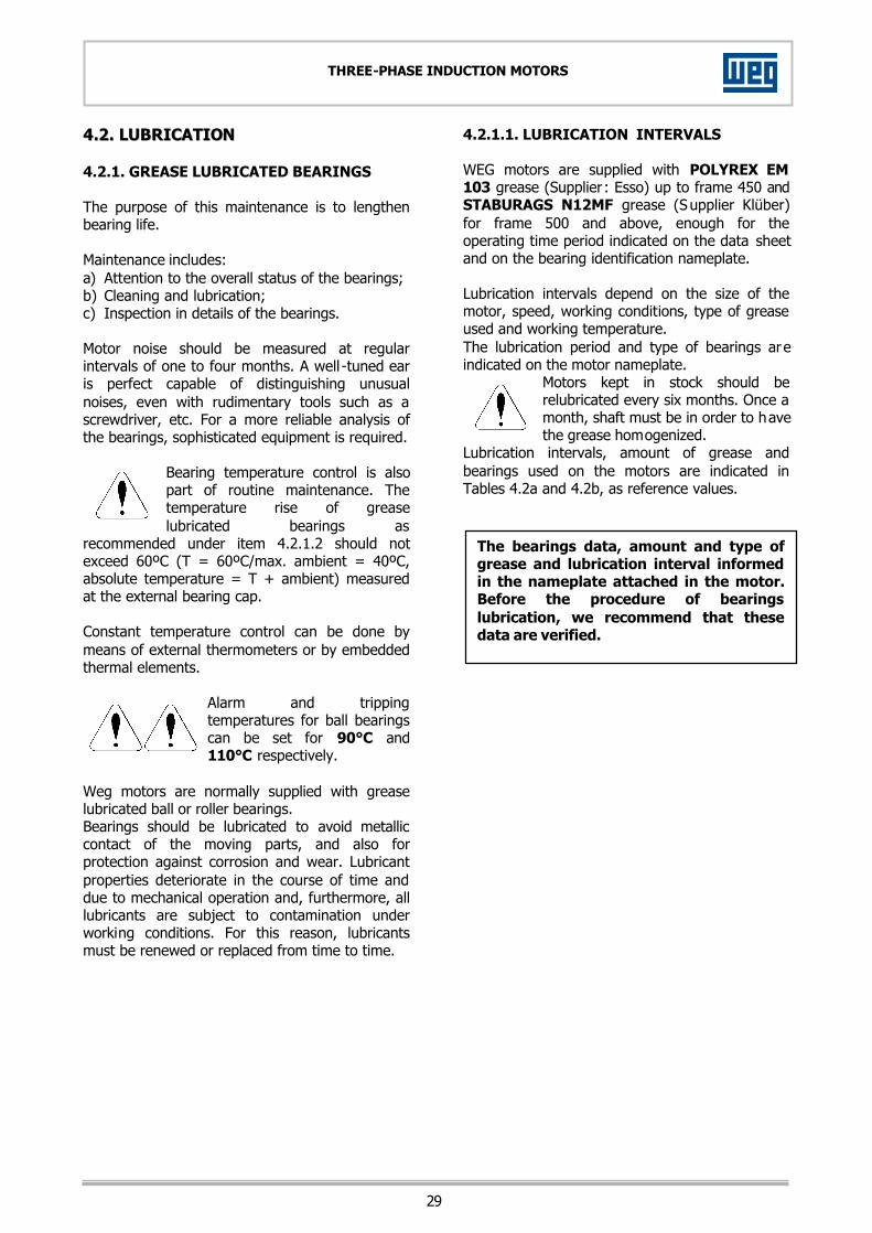
44..22.. LLUUBBRRIICCAATTIIOONN 4.2.1. GREASE LUBRICATED BEARINGS The purpose of this maintenance is to lengthen bearing life. Maintenance includes: a) Attention to the overall status of the bearings; b) Cleaning and lubrication; c) Inspection in details of the bearings. Motor noise should be measured at regular intervals of one to four months. A well -tuned ear is perfect capable of distinguishing unusual noises, even with rudimentary tools such as a screwdriver, etc. For a more reliable analysis of the bearings, sophisticated equipment is required.
Bearing temperature control is also part of routine maintenance. The temperature rise of grease lubricated bearings as
recommended under item 4.2.1.2 should not exceed 60ºC (T = 60ºC/max. ambient = 40ºC, absolute temperature = T + ambient) measured at the external bearing cap. Constant temperature control can be done by means of external thermometers or by embedded thermal elements.
Alarm and tripping temperatures for ball bearings can be set for 90°C and 110°C respectively.
Weg motors are normally supplied with grease lubricated ball or roller bearings. Bearings should be lubricated to avoid metallic contact of the moving parts, and also for protection against corrosion and wear. Lubricant properties deteriorate in the course of time and due to mechanical operation and, furthermore, all lubricants are subject to contamination under working conditions. For this reason, lubricants must be renewed or replaced from time to time.
4.2.1.1. LUBRICATION INTERVALS WEG motors are supplied with POLYREX EM 103 grease (Supplier : Esso) up to frame 450 and STABURAGS N12MF grease (Supplier Klüber) for frame 500 and above, enough for the operating time period indicated on the data sheet and on the bearing identification nameplate. Lubrication intervals depend on the size of the motor, speed, working conditions, type of grease used and working temperature. The lubrication period and type of bearings are indicated on the motor nameplate.
Motors kept in stock should be relubricated every six months. Once a month, shaft must be in order to have the grease homogenized.
Lubrication intervals, amount of grease and bearings used on the motors are indicated in Tables 4.2a and 4.2b, as reference values.
The bearings data, amount and type of grease and lubrication interval informed in the nameplate attached in the motor. Before the procedure of bearings lubrication, we recommend that these data are verified.

30
THREE-PHASE INDUCTION MOTORS
MAXIMUM LUBRICATION INTERVALS (IN HURS) FOR HORIZONTALLY MOUNTED MOTORS - 60Hz
DE Bearing DE Bearing (with pulley)
NDE Bearing (squirrel cage
rotor)
NDE Bearing slip ring motor (Fixed
brushes)
NDE Bearing slip ring rotor
(Lifting brushes) Frame Poles Bearing Relubr. Bearing Relubr. Bearing Relubr. Bearing Relubr. Bearing Relubr.
2 6314 3.400 6314 3.400 4 6.400 2.000 8.900 6.600 6.600 6 10.000 4.500 10.000 10.000 10.000
315
8 6320
10.000 NU322
6.400 6316
10.000 6222
10.000 6222
10.000 2 6314 3.400 6314 3.400 4 4.800 1.600 6.400 5.800 5.800 6 8.700 3.900 10.000 10.000 10.000
355
8 6322
10.000 NU324
5.800 6320
10.000 6224
10.000 6224
10.000 4 2.200 1.400 6.400 5.100 3.400 6 4.900 3.700 10.000 9.300 6.900 400 8
NU224 6.800
NU228 5.500
6320 10.000
6226 10.000
6230 9.800
4 2.200 4.800 3.400 6234 2.500 6 4.900 8.700 3.400 5.600 450 8
NU224 6.800
6322 10.000
6230 3.400
6234 8.400
4 1.800 4.800 3.400 2.500 6 4.300 8.700 6.900 5.600 500 8
NU226 6.200
6322 10.000
6230 9.800
6234 8.400
4 6 3.700 5.500 3.100 2.300 8
NU228 5.500 7.500 4.900 3.900
4 6 2.700 5.500 3.100 2.300
560
8 NU232
4.400
NU222
7.500
NU230
4.900
NU234
3.900 4 6 1.200 4.900 3.100 2.300 8 2.200 6.800 4.900 3.900
10 3.100 8.100 6.300 5.200 12
23032
3.800 9.000 7.300 6.200 4 6 8 1.600 6.800 4.900 3.900
10 2.400 8.100 6.300 5.200
630
12
23036
3.100
NU224
9.000
NU230
7.300
NU234
6.200 6 8 1.600 6.200 4.400 3.900
10 2.400 7.500 5.700 5.200 12
23036
3.100 8.400 6.700 6.200 6 8 1.300 6.200 4.400 3.900
10 2.000 7.500 5.700 5.200
710
12
23040
2.600
NU226
8.400
NU232
6.700
NU234
6.200
Grease: Polyrex EM 103 (Esso) Grease: Staburags N12MF (Klüber) Table 4.2a. NOTES: - Normal relubrication interval for ambient temperature of 40ºC and types of grease specified above; - For vertically mounted motors, reduce relubrication intervals by half; - Bearing operating temperature = 70ºC; - Apply correction factors given below for relubrication intervals of table above on the following cases:
- Operating temperature below 60ºC: 1.59. - Operating temperature of 70ºC to 80ºC: 0.63. - Operating temperature of 80ºC to 90ºC: 0.40.

31
THREE-PHASE INDUCTION MOTORS
MAXIMUM LUBRICATION INTERVALS (IN HURS) FOR HORIZONTALLY MOUNTED MOTORS - 50Hz
DE Bearing DE Bearing (with pulley)
NDE Bearing (squirrel cage
rotor)
NDE Bearing slip ring motor (Fixed
brushes)
NDE Bearing slip ring rotor
(Liftable brushes) Frame Poles Bearing Relubr. Bearing Relubr. Bearing Relubr. Bearing Relubr. Bearing Relubr.
2 6314 4.900 6314 4.900 4 8.300 3.000 10.000 8.500 8.500 6 10.000 5.700 10.000 10.000 10.000
315
8 6320
10.000 NU322
7.600 6316
10.000 6222
10.000 6222
10.000 2 6314 4.900 6314 4.900 4 6.500 2.500 8.300 7.700 7.700 6 10.000 5.100 10.000 10.000 10.000
355
8 6322
10.000 NU324
6.900 6320
10.000 6224
10.000 6224
10.000 2 6317 3.400 6317 3.400 4 3.300 2.300 8.300 6.900 4.800 6 6.100 4.900 10.000 10.000 8.700
400
8 NU224
7.900 NU228
6.700 6320
10.000 6226
10.000 6230
10.000 4 3.300 6.500 4.800 6234 3.700 6 6.100 10.000 8.700 7.300 450 8
NU224 7.900
6322 10.000
6230 10.000
6234 10.000
4 2.800 6.500 4.800 3.700 6 5.500 10.000 8.700 7.300 500 8
NU226 7.300
6322 10.000
6230 10.000
6234 10.000
4 2.300 3.900 1.900 1.300 6 4.900 6.800 4.300 3.300 8
NU228 6.700 8.600 6.100 5.000
4 6 3.800 6.800 4.300 3.300
560
8 NU232
5.500
NU222
8.600
NU230
6.100
NU234
5.000 4 6 1.800 6.100 4.300 3.300 8 2.900 7.900 6.100 5.000
10 3.800 9.000 7.300 6.200 12
23032
4.400 9.600 8.000 7.100 4 6 1.300 6.100 4.300 3.300 8 2.300 7.900 6.100 5.000
10 3.100 9.000 7.300 6.200
630
12
23036
3.700
NU224
9.600
NU230
8.000
NU234
7.100 6 1.300 5.500 3.800 3.300 8 2.300 7.300 5.500 5.000
10 3.100 8.400 6.700 6.200 12
23036
3.700 9.100 7.600 7.100 6 1.000 5.500 3.800 3.300 8 1.800 7.300 5.500 5.000
10 2.600 8.400 6.700 6.200
710
12
23040
3.200
NU226
9.100
NU232
7.600
NU234
7.100
Grease: Polyrex EM 103 (Esso) Grease: Staburags N12MF (Klüber) Table 4.2b. NOTES: - Normal relubrication interval for ambient temperature of 40ºC and types of grease specified above; - For vertically mounted motors, reduce relubrication intervals by half; - Bearing operating temperature = 70ºC; - Apply correction factors given below for relubrication intervals of table above on the following cases:
- Operating temperature below 60ºC: 1.59. - Operating temperature of 70ºC to 80ºC: 0.63. - Operating temperature of 80ºC to 90ºC: 0.40.
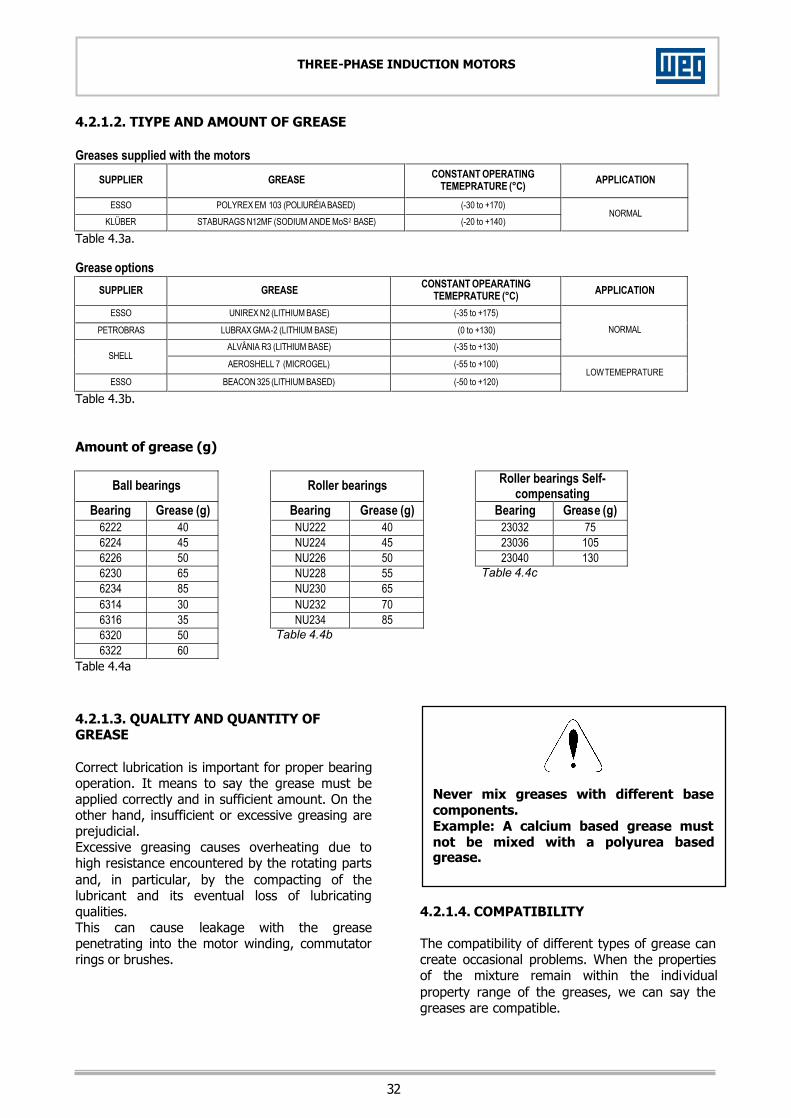
32
THREE-PHASE INDUCTION MOTORS
4.2.1.2. TIYPE AND AMOUNT OF GREASE Greases supplied with the motors
SUPPLIER GREASE CONSTANT OPERATING TEMEPRATURE (°C) APPLICATION
ESSO POLYREX EM 103 (POLIURÉIA BASED) (-30 to +170) KLÜBER STABURAGS N12MF (SODIUM ANDE MoS2 BASE) (-20 to +140)
NORMAL
Table 4.3a. Grease options
SUPPLIER GREASE CONSTANT OPEARATING TEMEPRATURE (°C) APPLICATION
ESSO UNIREX N2 (LITHIUM BASE) (-35 to +175)
PETROBRAS LUBRAX GMA-2 (LITHIUM BASE) (0 to +130) ALVÂNIA R3 (LITHIUM BASE) (-35 to +130)
NORMAL
SHELL AEROSHELL 7 (MICROGEL) (-55 to +100)
ESSO BEACON 325 (LITHIUM BASED) (-50 to +120) LOW TEMEPRATURE
Table 4.3b. Amount of grease (g)
Ball bearings Roller bearings Roller bearings Self-compensating
Bearing Grease (g) Bearing Grease (g) Bearing Grease (g) 6222 40 NU222 40 23032 75 6224 45 NU224 45 23036 105 6226 50 NU226 50 23040 130 6230 65 NU228 55 Table 4.4c 6234 85 NU230 65 6314 30 NU232 70 6316 35 NU234 85 6320 50 Table 4.4b 6322 60
Table 4.4a
4.2.1.3. QUALITY AND QUANTITY OF GREASE Correct lubrication is important for proper bearing operation. It means to say the grease must be applied correctly and in sufficient amount. On the other hand, insufficient or excessive greasing are prejudicial. Excessive greasing causes overheating due to high resistance encountered by the rotating parts and, in particular, by the compacting of the lubricant and its eventual loss of lubricating qualities. This can cause leakage with the grease penetrating into the motor winding, commutator rings or brushes.
4.2.1.4. COMPATIBILITY The compatibility of different types of grease can create occasional problems. When the properties of the mixture remain within the individual property range of the greases, we can say the greases are compatible.
Never mix greases with different base components. Example: A calcium based grease must not be mixed with a polyurea based grease.

33
THREE-PHASE INDUCTION MOTORS
To avoid any possible incompatibility grease problem we recommend performing an appropriate lubrication which can be summarized as follows: after removing the old grease and caring out a complete cleanliness of the grease cavity, new grease must be pumped in. When this procedure is not allowed, pump in new grease by pressure. This must be repeated until new grease is drained out through the grease relief. As a general rule, greases with same soap type are compatible. However depending on the mixture rate, they can then be recommended to mix different types of grease before contacting a service agent and/or WEG. Same and basic oils can not be mixed as they will not produce a homogeneous mixture. In this case, either a hardening or a softening (or drop of the resulting mixture melting point) can occur. 4.2.1.5. LUBRICATING INSTRUCTIONS The lubrication system was designed to allow, when regreasing, the removal of all grease from the bearings races through a grease relief which at the same time impedes the entry of dust or other contaminants harmful to the bearing. This grease relief also avoids injury to the bearings from the already known problem of over-greasing. It is advisable to relublicated while the motor is running so as to allow the renewal of grease in the bearings housing. If this procedure is not possible due to existing parts near to the nipple (pulleys, etc), which can be harmful to the operator, the following procedure should be followed: - Inject about half the estimated amount of
grease and run the motor at full speed for approximately one minute;
- Switch off the motor and inject the remaining grease.
The injection of all the grease with the motor stopped can cause penetration of a portion of the lubricant into the motor through the internal seal of the bearing housing. NOTE: Grease fittings must be clean before greasing the motor in order to avoid entry of any foreign bodies into the bearing.
For lubrication, use only a manual grease gun. Figure 4.2. - Bearings and lubrication system. 4.2.1.6. BEARING LUBRICATION STEPS 1. Remove the grease relief cover. 2. Clean the area around the grease fitting with a
clean cotton fabric. 3. With the motor running, add grease with a
manual grease gun until the lubricant commences to expel from the grease relief, or insert the amount of grease recommended in Tables herewith indicated.
4. Leave the motor running enough time to drain all excess of grease.
5. Check bearing temperature to make sure there has not been any major variation.
4.2.1.7. SPRING DEVICE FOR GREASE REMOVAL When grease outlet is not accessible to the operator, some motors are fitted with a spring device for grease removal during bearing relubrication. Lubrication steps: 1. Before starting bearing lubrication procedure,
clean the grease fitting with a piece of coth; 2. Remove the spring through bolt, clean the
spring and place it back; 3. With the rotor in operation, add the amount of
grease specified on the bear ing identification nameplate with the application of a manual grease gun.
4. The excess of grease will be drain it through the bottom grease relief and is dropped on the spring.
5. Keep the motor running for a time period enough to drain out all excess of grease.

34
THREE-PHASE INDUCTION MOTORS
6. This grease must be removed by pulling the spring through bolt and then cleaning the spring. This procedure must be carried out as many times as it is required up to the point no grease is on the spring.
7. Check bearing temperature to make sure there has not been any major modification.
Figure 4.3. – Example of a vertically mounted NDE bearing with grease outlet fitted with spring device. 4.2.1.8. REPLACEMENT OF BEARINGS After removing the bearing cap, avoid demage to the cores by filling the air gap between the rotor and the stator with stiff paper of a proper thickness. Providing suitable tooling is employed, disassembly of bearings is not difficult. (See bearing extractor with 3 grips in figure 4.4). Figure 4.4. - Bearing Extractor. The extractor grips must be applied to the sidewall of the inner ring to be stripped, or to an adjacent part. To ensure perfect functioning and no injury to the bearing parts, it is essential that the assembly be done under conditions of complete cleanliness and by skilled personnel. New bearings should not be removed from their packages until they are assembled. Prior to fitting a new bearing, ascertain that the shaft has no rough edges or signs of hammering.
During assembly, bearings cannot be subjected to direct blows. To make the assembly easier, it is recommended to heat up (inductive heater) the bearing. The aid used to press or strike the bearings should be applied to the inner ring. 4.2.2. ANTIFRICTION BEARIGS LUBRICATED BY GREASE – VERTICAL MOTORS 4.2.2.1. CHARACTERISTICS The bearings characteristics data, amount and type and quantity of grease and lubrication interval are informed in the nameplate attached in the motor. 4.2.2.2. RELUBRICATION STEPS 1) Before lubricating the bearing, clean the
grease fitting nipples with cotton fabric; 2) Remove the spring bolt at the grease outle t
(17), clean the spring and replace it. 3) With the motor in operation, add amount of
grease indicated on the bearing nameplate with the application of a manual grease gun.
4) Excess of grease will drain out through the bearing bottom drain and dropped in the spring.
5) Leave the motor running for a time period enough to drain out all excess of grease.
6) This grease must be removed by pulling the through bolt and cleaning the spring as many times it is required until completely drained out.
7) Check bearing temperature to make sure there has not been a significant variation.
Bearing repair and replacement If is necessary cleaning the bearing or remove it for maintenance, follows the instructions below:
Grease inlet
Grease removal spring

35
THREE-PHASE INDUCTION MOTORS
4.2.2.3. DISASSEMBLY / ASSEMBLY – OPPOSITE DRIVE-END BEARING
Before disassembly - Remove the prolongation tubes of the grease
inlet and outlet; - Remove the sun shade, cover, fan and other
components that are in the rear side as sun as the shaft end becomes free for bearing removing.
- Clean completely the outside of bearings. - Remove the temperature detectors from the
bearings and provide a prop for support the shaft and avoid damages.
Opposite drive-end bearing disassembly Care must be taken to avoid damage on the ball or roller and shaft surface. For disassemble the bearing, follows carefully the instructions below: Keeps all the parts disassembled in an insurance local. 1) Remove the fixation nut (16) 2) Remove the grease relief (17); 3) Remove the closed external ring (6); 4) Remove the screws (12) which fasten the
external bearing cap; 5) Remove the external bearing cap (2); 6) Remove the screws (11 and 13); 7) Remove the rear cover (8); 8) Remove the external bearing (14), separator
ring (4) and internal bearing (15); 9) Remove the screw which fasten the grease
valve (3) and remove it; 10) Remove the internal bearing cap (1) if
necessary.
Opposite drive-end bearing reassembly - Clean the bearings completely and inspects the
removed parts and the interior of the caps. - Certify that the bearing, shaft and bearing
caps surfaces be smooth. - Put the recommended grease
on ¾ of the external and internal bearing cap deposit and lubricate the bearing with
sufficient quantity of grease before reassemble it.
- Before place the bearing on the shaft, heat the bearing to a temperature between 50ºC and 100ºC. For reassembling the bearings, follow the instructions of disassembly in the inverse order.
Temperature detectors detail
1- Internal bearing cap 2- External bearing cap 3- Grease valve 4- Separator ring 5- Cover grease 6- Closed external ring 7- Spring cover protection 8- Rear cover 9- Pre-loading spring 10- Internal bearing cap 11- Fixation screw 12- Fixation screw 13- Fixation screw 14- External bearing 15- Internal bearing 16- Fixation nut 17- Grease relief 18- Grease relief 19- Press washer

36
THREE-PHASE INDUCTION MOTORS
4.2.2.4. DISASSEMBLY / ASSEMBLY – DRIVE-END BEARING
Before disassembly - Remove the prolongation tubes of the grease
inlet and outlet (if any); - Clean completely the outside of bearings; - Remove the temperature detectors fr om the
bearings; - Remove the grounding brush (if any); - Provide a prop for support the shaft and avoid
damages. Drive-end bearing disassembly Care must be taken to avoid damage on the ball or roller and shaft surface. For disassemble the bearing, follows carefully the instructions below: Keeps all the parts disassembled in an insurance local. 1) Remove the screws (4) which fasten the seal
disc (13). 2) Remove the ring with labyrinth (6); 3) Remove the screws (3) which fasten the
bearings cap (1 and 5); 4) Remove the external bearing cap (5); 5) Remove the screw (7) which fasten the grease
valve (8); 6) Remove the grease valve (8); 7) Remove the front cover; 8) Remove the bearing (10). 9) Remove the internal bearing cap (1), if
necessary.
Drive-end bearing reassembly - Clean the bearings completely and inspects
the removed parts and the interior of the caps. - Certify that the bearing, shaft and bearing
caps surfaces be smooth. - Put the recommended grease on
¾ of external and internal bearing cap deposit and lubricate the bearing with sufficient quantity of grease before
reassemble it. - Before places the bearing on the shaft, heat
the bearing to a temperature between 50ºC and 100ºC.
For reassembling the bearings, follow the instructions for disassembly in inverse order.
1- Internal bearing cap 2- White felt 3- Screw that fixes the bearing caps 4- Screw that fixes the seal disc 5- External bearing cap 6- Ring with labyrinth 7- Screw which fasten the grease valve 8- Grease valve 9- Drawer for waste grease 10- Bearing 11- Grease nipple 12- Thermal protective 13- Seal disc

37
THREE-PHASE INDUCTION MOTORS
4.2.3. ANTIFRICTION BEARING LUBRICATED BY OIL
4.2.3.1. LUBRICATION INSTRUCTIONS Oil removal When re-lubrication is necessary, please remove the oil outlet (3) and oil inlet (1) plugs and quit the oil completely. For oil insertion in the bearing: - Close the oil outlet (3) with the drain plug; - Remove the filter in the oil inlet (1), if any. - Add the type and amount of oil up to the level
indicated in the oil sight glass. NOTES: 1) Make sure that all the openings are closed and
that there is no indication of oil leakage in the oil reservoir or seals.
2) The proper oil level is obtained when the lubricant can be seen in the middle of the oil sight glass.
3) Excessive amount of oil will not damage the bearings, but it can cause the oil to l eak through the seals.
Oil characteristics The type of lubricant, lubrication interval and type of bearings are indicated on the motor nameplate like to the bearing. IMPORTANT: The bearings lifetime, their operating condi tions and motor operating conditions will depend on the procedures followed by the maintenance personnel. The following recommendations must be observed. - The oil selected for the application must ha ve
the adequate viscosity for the bearing operating temperature. The type of oil recommended by WEG already considers th ese criteria.
- Insufficient amount of oil can damage the bearings.
- The minimum recommended oil level is reached when the lubricant can be seen touching the bottom part of the oil sight glass, with the motor in the idle condition.
The oil level must be checked daily, being kept approximately in the middle of the oil sight glass.
4.2.3.2. BEARING OPERATION The operation of motors equipped with oil-lubricated bearings is similar to the operation of motors equipped with grease-lubricated bearings. The bearings performance during start up must be carefully checked as well as their performance during the first running hours. Before running the motor, check: - If the oil being used is the same as the oil
recommended on the bearings nameplate. - The oil characteristics; - The oil level; - The alarm and trip point for bearings
temperatures; During the first starting, pay special attention for excessive vibration or noise when the motor is running uncoupled. The motor and bearings should operate quietly and under low vibr ation. Have a copy of the factory vibration test report so you can compare the results obtained during the test with the results obtained after the installation. The motor must run for several hours until the temperature of the bearings stabilize. If abnormal bearing operating temperature is noticed, the motor must be shut down and the installation, bearings and sensors must be re-checked. Check the whole bearing system (oil reservoir, seals) to make sure there is no oil leakage. 4.2.3.3. THERMAL PROTECTIONS SETTING Each bearing is fitted with a Pt100 temperature detector installed directly in the bearing liner near the point where the load is applied. This device must be connected to a controlling panel with the purpose of detecting overheating and protect the bearing when operating under high temperature.
IMPORTANT: The following temperature must be set on the bearing protecting system:
ALARM 100ºC TRIPPING OFF 120ºC
1
2
3
1- Oil inlet 2- Oil sight glass 3- Oil outlet 4- Temperature sensor
4
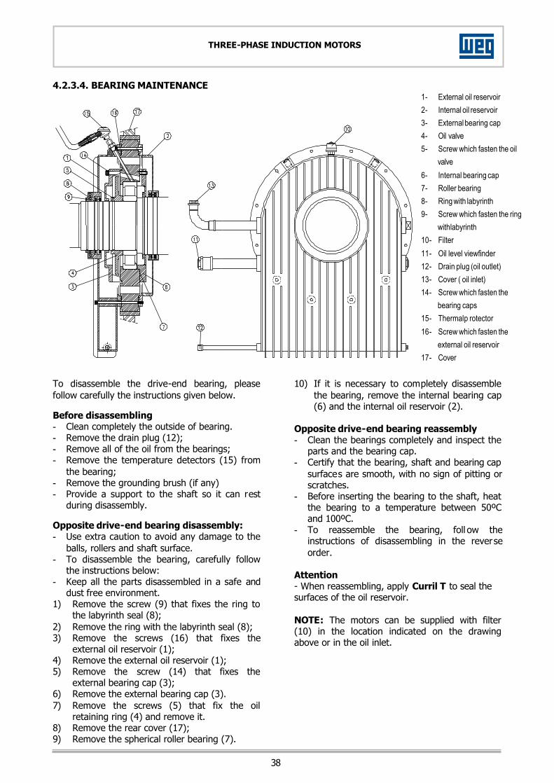
38
THREE-PHASE INDUCTION MOTORS
4.2.3.4. BEARING MAINTENANCE
To disassemble the drive-end bearing, please follow carefully the instructions given below. Before disassembling - Clean completely the outside of bearing. - Remove the drain plug (12); - Remove all of the oil from the bearings; - Remove the temperature detectors (15) from
the bearing; - Remove the grounding brush (if any) - Provide a support to the shaft so it can rest
during disassembly. Opposite drive-end bearing disassembly: - Use extra caution to avoid any damage to the
balls, rollers and shaft surface. - To disassemble the bearing, carefully follow
the instructions below: - Keep all the parts disassembled in a safe and
dust free environment. 1) Remove the screw (9) that fixes the ring to
the labyrinth seal (8); 2) Remove the ring with the labyrinth seal (8); 3) Remove the screws (16) that fixes the
external oil reservoir (1); 4) Remove the external oil reservoir (1); 5) Remove the screw (14) that fixes the
external bearing cap (3); 6) Remove the external bearing cap (3). 7) Remove the screws (5) that fix the oil
retaining ring (4) and remove it. 8) Remove the rear cover (17); 9) Remove the spherical roller bearing (7).
10) If it is necessary to completely disassemble the bearing, remove the internal bearing cap (6) and the internal oil reservoir (2).
Opposite drive-end bearing reassembly - Clean the bearings completely and inspect the
parts and the bearing cap. - Certify that the bearing, shaft and bearing cap
surfaces are smooth, with no sign of pitting or scratches.
- Before inserting the bearing to the shaft, heat the bearing to a temperature between 50ºC and 100ºC.
- To reassemble the bearing, foll ow the instructions of disassembling in the reverse order.
Attention - When reassembling, apply Curril T to seal the surfaces of the oil reservoir. NOTE: The motors can be supplied with filter (10) in the location indicated on the drawing above or in the oil inlet.
1- External oil reservoir 2- Internal oil reservoir 3- External bearing cap 4- Oil valve 5- Screw which fasten the oil
valve 6- Internal bearing cap 7- Roller bearing 8- Ring with labyrinth 9- Screw which fasten the ring
with labyrinth 10- Filter 11- Oil level viewfinder 12- Drain plug (oil outlet) 13- Cover ( oil inlet) 14- Screw which fasten the
bearing caps 15- Thermal p rotector 16- Screw which fasten the
external oil reservoir 17- Cover

39
THREE-PHASE INDUCTION MOTORS
4.2.4. SLEEVE BEARINGS
Figure 4.5. 1) Drain plug;
2) Bottom half of the bearing housing;
3) Motor frame cover;
4) Fixing bolts;
5) Top half of the bearing housing;
6) Bearing housing cap split line bolt;
7) Machine seal;
8) Machine seal bolt;
9) Lifting eyebolt;
10) External cover bolts;
11) External cover;
12) Bearing liner - bottom half;
13) Bearing liner - top half;
14) Oil ring;
15) Oil inlet;
16) Connection for temperature sensor;
17) Oil sight glass or oil outlet for lubrication
18) Tapped hole for oil sump temperature
measurement;
19) Stationary baffle bolt;
20) Labyrinth seal carrier (outboard);
21) Labyrinth seal carrier (inboard) – bearing-
housing.
22) Breathing pipe

40
THREE-PHASE INDUCTION MOTORS
4.2.4.1. GENERAL INSTRUCTIONS Sleeve bearing performance is dependent on proper installation, lubrication and maintenance. Before assembling the bearing carefully read all instructions contained herein to become familiar with the complete bearing assembly procedure. A proper maintenance of sleeve bearings include periodical checking of the level and actual condition of the lubricating oil, checking of noise level and vibration of the bearings, follow-up of the operating temperature, and fastening of the fixing and assembly bolts. The frame must be kept clean, free from dust, oil and dirt to facilitate cooling system. Threaded holes for connecting the thermometer, oil sight glass, oil inlet, and immersion heater, or cooling coil (for oil sump thermometer or circulating pump with adapter) are provided on either side, so that all connections can be made on the right or left side of the bearing housing as required. The oil drain plug is located centrally on the underside of the bearing housing. In case of circulating oil lubrication, the outlet connection should be screwed into the threaded hole of an oil sight glass. If the bearing is electrically insulated, the spherical liner seat surfaces in the housing are lined with a non-conducting material. Do not remove this lining. The antirotation pin is also insulated and the shaft seals are manufactured from a special non-conducting material. Temperature monitoring instruments with contact to the bearing liner should be insulated appropriately (i.e., insulated protection tubes, synthetic fittings, etc.) Water-cooled bearings are provided with the cooling coil installed. Care must be taken to protect the connections from damage when handling the housing prior to installation. 4.2.4.2. DISASSEMBLY OF THE SLEEVE BEARING SYSTEM (TYPE "EF") To disassemble the bearing liner and all associated parts from the bearing housing, carry out the following instructions. Carefully store all disassembled parts in a safe location (see figure 4.5). Drive end side: - Throughly clean the exterior of the bearing
housing. Loosen and remove the oil drain plug (1) at the bottom of the bearing housing. Drain the oil from the bearing housing.
- Loosen and remove the bolts (4) that connect the top half of the bearing housing (5) to the motor frame cover(3).
- Loosen and remove the bolts (6) that join the top and bottom half of the bearing housing (2 and 5).
- Use the lifting eyebolts (9) to lift (by hand or hoist) the top half of bearing housing(5) straight up, so that the cap is completel y disengaged from the lower halves of the stationary baffle (11) labyrinth seals, labyrinth seal carrier (20) , and the bearing liner (12).
- Pull the top bearing housing forward out of and away from the bearing area. Loosen and remove the bolts (19) securing the top half of the stationary baffle. Loosen and remove the bolts (10) securing the upper half of the seal carrier (20).
- Lift (by hand or hoist) the upper half of the bearing liner (13) and remove it.
- Loosen and remove the bolts at the spli t line of the oil ring (14). Carefully disengage the dowels holding the oil ring halves together and remove the oil ring.
- Remove the garter springs that encircle the labyrinth seals and remove the top half of each seal. Rotate the bottom half of each seal out of the grooves in the seal carrier and bearing housing and remove them.
- Disconnect and remove RTD's, thermocouples, or any other temperature detecting instruments that enter the lower half of the bearing liner.
- Using a hoist or jack, raise the shaft slightly so that the lower half of the bearing liner can be rolled out of the bearing housing.
IMPORTANT: To make that feasible it is necessary that bolts 4 and 6 of the other bearing half be loose. - Roll out (be careful not to use excessive force)
the lower half of the bearing liner and remove it.
- Loosen and remove the bolts (19) securing the bottom half of the stationary baffle (11) to the seal carrier. Loosen and remove the bolts (10) securing the bottom half of the seal carrier (20) to the bearing housing . Remove the seal carrier.
- Loosen and remove the bolts (4). Remove the bottom bearing housing (2).
- Remove the frame cover (3). - Loosen and remove the bolts (8) securing the
machine seal (7) to the frame cover. Remove the machine seal.
- Thoroughly clean and inspect all individual parts which have been removed. Clean the interior of the bearing housing.
- To reassemble the bearing system, follow the preceding instructions in the reverse order.
NOTE: Festening torque of the bearing fixing bolts to the motor = 10 Kgfm. Non drive end side: - Thoroughly clean the exterior of the bearing
housing. Loosen and remove the oil drain plug (1) at the bottom of the bearing housing. Drain the oil from the bearing housing.

41
THREE-PHASE INDUCTION MOTORS
- Loosen and remove the bolts (19) and remove the external cover (11).
- Loosen and remove the bolts (4) that fix the top bearing housing (5) to the motor frame cover(3).
- Loosen and remove the bolts (6) that join the top and bottom half of the bearing housing (2 and 5).
- Use the lifting eyebolts (9) to lift (by hand or hoist) the top half of the bearing housing (5) straight up, that the cap is completely disengaged from the lower halves of the bottom bearing housing (2) and the bearing liner (12).
- Lift (by hand or hoist) the top half of the bearing liner (13) and remove it.
- Loosen and remove the bolts at the split line of the oil ring (14). Carefully disengage the dowels holding the oil ring halves together and remove the oil ring.
- Remove the garter spring that encircles the labyrinth seal. Remove the top half of the seal, then rotate the bottom half of the seal out the groove in the bearing housing and remove it.
- Disconnect and remove RTD's, thermocouples, or any other temperature detecting instruments that enter the lower half of the bearing liner.
- Using a hoist or jack, raise the shaft slightly so that the lower half of the bearing liner (12) can be rolled out of the bearing housing.
- Roll out (be careful not to use excessive force) the bottom half of the bearing liner (12) and remove it.
- Loosen and remove the bolts (4) and remove the bottom bearing housing (2).
- Remove the motor frame cover (3). - Loosen and remove the bolts (8) and remove
the machine seal (7). - Thoroughly clean and inspect all individual
parts which have been removed. Clean the interior of the bearing housing.
To reassemble the Bearing System, follow he preceding instructions in the reverse order. NOTE: Fastening torque of the bearing fixing bolts to the motor = 10 Kgfm. 4.2.4.3. SLEEVE BEARING ASSEMBLY Check contact face and mounting recess of the bracket making sure it is clean and properly machined. Inspect shaft to ensure it is smooth (Ra 0.4, equivalent to 32 micro-inch finish, or better), within the dimensions and tolerances given by RENK and free of burr or any rough spots. After removing the upper part of the housing (2) and the bearing liner (12 and 13) the interior of the housing and the running surfaces of the liner are to be cleaned thoroughly and checked for any damage caused in transit. With the shaft slightly, locate the bearing base into the mounting recess of the machine end shield and bolt into position.
Apply oil to spherical seats in the housing base and the shaft and rotate the bottom liner half (12) into position. Special care must be taken so that the axial surfaces of the locating bearing are not damaged. After the split faces of the bottom liner half and the housing base are aligned, lower the shaft into place. With a slight hammer blow against the housing base settle the liner into its seating so that the liner axis and shaft axis are parallel. The slight hammer blow produces a high fr equency vibration which reduces the static friction between the liner and the housing and allows the correct adjustment of the liner. The self-alignment feature of the bearing is to compensate for normal shaft deflection during the assembling procedure only. The loose oil ring is installed next. The ring must be handled with special care as safe operation of the bearing is also dependent on the effective and safe functioning of the oil ring. The bolts must be tightly fastened. Split misalignment must be avoided and any burrs or edges carefully removed in order to ensure smooth running of the ring. In any maintenance care must be taken that the ring is not distorted and its geometrical shape is maintained. The outside of the two liner halves is stamped with identification numbers or marks near the split line. Make sure that these marks align and the split faces are clean when placing the top liner half into position. Incorrect fitting may lead to heavy damage to the bearing liners. Check to ensure that the loose oil ring can still rotate freely on the shaft. With the top liner half in place, install the seal on the flange side (see paragraph "Shaft Seals"). After coating the split faces with a non-hardening sealing compound, place the housing cap into position. Care must be taken that the seal fits properly into the groove. Ensure also that the anti-rotation pin is seated without any contact with the corresponding hole in the liner.
NOTE: Housing or liner may be interchanged as complete assemblies only. Individual halves are not interchangeable.
4.2.4.4. SETTING OF THERMAL PROTECTIONS (PT100) Each bearing is fitted with a Pt100 temperature detector installed directly in the bearing liner near the point where the load is applied. This device must be connected to a controlling panel with the purpose of detecting overheating and protect the bearing when operating under high temperature.

42
THREE-PHASE INDUCTION MOTORS
IMPORTANT: The following temperature must be set on the bearing protecting system:
ALARM 100ºC TRIPPING OFF 120ºC 4.2.4.5. WATER COOLING SYSTEM When using water cooling system, the oil reservoir at the bearing is equipped with cooling coils through which the water circulates. This circulating water must present at the bearing inlet a temperature smaller or equal to the ambient one in order to make the cooling possible. The water pressure must be 0.1 bars and the water flow must be 0.7 L/s. The pH must be neutral.
NOTE: When connecting the cooling coils, leaks in or on the bearings housing and oil reservoir must be avoided so that lubricating oil is not
contaminated. 4.2.4.6. LUBRICATION The oil change of the bearings must be effected every 8000 operating hours, or every time the oil modifies its characteristics. Viscosity and oil pH must be checked periodically.
Oil level must be checked daily which must be kept approximately at the center of the oil level sight glass.
The bearing must be filled with the prescribed type of oil through the oil port after removing the pipe plug. All holes and threads not used are to be closed by pipe plugs. Also check all connections for oil leaks. Filling the bearing with lubricant beyond the middie of the oil sight glass (II) does not impair the function of the bearing, but there is a possibility that excess oil may leak out through the shaft seals.
IMPORTANT: The cares taken with bearing lubrication will determine the life for such bearings as well as the assurance of motor operation. For
this reason, it is essential to follow these recommendations:
- The oil selected must have a viscosity suitable for the bearing operating temperature. This must be checked during eventual oil change or during periodical maintenances.
- If the bearing is filled with oil bellow the required oil level, or if the oil level is n ot checked periodically, insufficient lubrication may lead to damage to the bearing liner. The minimum oil level is reached when the oil can just be seen in the oil sight glass when the machine is not in operation.
4.2.4.7. SHAFT SEALS The two halves of the floating labyrinth seal are held together by a garter spring. They must be inserted into the groove of the carrier ring in such a way that the stop pin is always in the corresponding recess in the upper half of the housing or carrier ring. Incorrect installation destroys the seal. The seal is to be carefully cleaned and coated with a non-hardening seating compound on the faces in contact with the grooves. The drain holes in the lower part of the seal must be clean and remove obstruction. When installing the bottom half of the seal, press it lightly against the underside of the shaft. An additional sealing is installed inside the motor to prevent sucking of oil due to low pressure generated by the motor cooling system. 4.2.4.8. OPERATION The operation of motors fitted with sleeve bearings is similar to motors fitted with roller bearings. It is recommended that the oil circulating system be accompanied carefully and also the first hours of operation. Before the start-up, check the following: - If the oil used has been prescribed
accordingly. - Characteristics of the lubricating oil. - Oil level. - Alarm and tripping off temperatures set for the
bearings (100ºC for alarm and 120ºC for tripping off).
During the first start-up, check for vibrations or noises. In case bearing operation is not quiet and not uniform, motor is to be stopped at once. Motor must operate for several hours until the bearing temperature is fixed within the limits previously indicated. If a temperature overheating occurs, motor must be stopped immediately and the temperatures detectors checked.

43
THREE-PHASE INDUCTION MOTORS
When bearing operating temperature is reached check for any oil leakage by the plugs joints or by the shaft end. 44..33.. AAIIRR GGAAPP CCHHEECCKKIINNGG ((LLaarrggee OODDPP mmoottoorrss)) After disassembly and assembly of the motor it is necessary to check the air gap measurement between the stator and the rotor by using appropriate gauges. The gap variation at any two vertically opposite points must be less than 10% of the average air gap measurement. 44..44.. SSLLIIPP RRIINNGGSS ((FFoorr sslliipp rriinngg mmoottoorrss)) Rings must be accurately centered as at high speed the mechanical vibrations cause contact faults, which in turn cause sparking. Rings must also be kept clean and polished. As a general rule, cleaning should be done monthly in order to remove the dust accumulated between the rings (see item 4.10). Stained or slightly rough ring surfaces can be polished with fine sandpaper. Oval or rough surfaced rings will require machining and repolishing to avoid wear problems to brushes and brush-holders. 44..55.. BBRRUUSSHH--HHOOLLDDEERRSS AANNDD BBRRUUSSHHEESS ((ffoorr wwoouunndd rroottoorr mmoottoorrss)) Brush holders must be set radially to the slip ring and adjusted approximately 4mm away from the contact surface to avoid brush rupture or injury (figure 4.6).
CORRECT INCORRECT Figure 4.6 – Brush-holder assembly. OBS.: Brushes must be checked weekly to ensure free sliding inside the brush-holder.
Brushes There is a factory-specified brush type for each electric motor fitted with slip rings.
NOTA: In case motor is operating below its rated output (low load) or intermittent load, the set of brushes (brush type and quantity) must be
adjusted to the actual operating conditions, avoiding in this way motor damage. This adjustment must be done with the help of Weg Máquinas. Never use assorted brushes of different types on the same rings. Any change of brush type must be authotized by WEG Máquinas, as different brushes cause performance alterations to the machine in operation. Brushes should be constantly checked during operation. Any brush presenting signs of wear should be exceeding the mark indicated figure 4.7, immediately replaced. At the time of replacement and whenever feasible, all brushes should be replaced. Having replaced the first one, the second brush should be replaced after a suitable running-in-period. Replacement brushes should be sanded to set perfectly on the ring surface curvature (min. 75%). Figure 4.7 – Brush wear mark. On machines that always rotate in the same direction, the brushes should be set in a single direction only. During the backward movement of the shaft the brushes must be lifted (figure 4.8).

44
THREE-PHASE INDUCTION MOTORS
Figure 4.8 – Brush contact face. Brushes must be fitted with identical pressure on the contact surface so as to ensure regular current balance and low brush wear. It is important that all brushes have the same pressure with a tolerance of approximately 10%. Higher deviations lead to irregular current balance with consequent irregular wear. Brush pressure control is done with the application of a dynamometer. "Tired" springs must be replaced. 4.5.1. SHAFT GROUNDING DEVICE On some induction motors, specially those requiring speed control due to frequency inverter application, a set of brush holder and brushes for shaft grounding is used. This devices avoids electric current going through the bearings, which are highly harmful to their operation. The brush is put in contact with the shaft and connected to the machine frame through a cable, which must be also grounded.
Fig. 4.9 – Shaft grounding brush. To avoid shaft damage on WEG motors during transportation, shaft ends are protected with protective oil. For a correct Grounding Brush operation, this protective oil must be removed from the shaft surface before motor operation as well as any foreign materials that may be present between shaft and the brush.
Brush must be checked on permanent basis while in operation and, when getting to the end of its life time, must be replaced by another of same quality (granulation).
Shaft

45
THREE-PHASE INDUCTION MOTORS
44..66.. LLIIFFTTAABBLLEE BBRRUUSSHH HHOOLLDDEERRSS 4.6.1. CONNECTION DIAGRAM AUTOMATIC OPERATION: Operating condition with brushes at lower position and slip ring not short-circuited. To ensure brushes are kept lowered, the switches: - CCA1 - contacts 34 and 35, - CCA2 - contacts 22 and 23, - CCD - contacts 13 and 14, must be simultaneously close (logic "AND"). With this logic, motor is suitable to start.
Description of components: A - Electromechanical Actuator ATIS Type: MAI-25.B3.d9-25.10-F10-2CC-2CT-IP65 B - Three-phase induction motor FS 71 6 pole, 0.25kW, Mounting B3L, IPW55 Flange C105-DIN 42948 Voltage and frequency as per client request. C - End-of-course Type XCK-P121 – Telemecanique
Figure 4.10.

46
THREE-PHASE INDUCTION MOTORS
Condition: Lifted brushes and short circuited collector ring. In order to assure the brushes are lifted, the switches: - CCL1 - contacts 37 and 38,
- CCL2 - contacts 25 and 26, - CCE - contacts 16 and 17, must have the
contacts simultaneously closed (logic "AND"). At this condition the motor is in continuous operation.
Figure 4.11.

47
THREE-PHASE INDUCTION MOTORS
MANUAL OPERATION:
Figure 4.12. Simbology: CLD = Torque switch for overload switching off during lowering of the brushes (or phase reversion). In case of fault on the CCD.
Figure 4.13. CLE = Torque switch for overload switching off during lifting of the brushes (or phase reversion). In cause the fault on the CCE.
Figure 4.14. CCD = End-of-course switch for switching off when brushes are totally lowered. CCE = End-of-course switch for switching off when brushes are totally lifted. CLR = Selecting switch indicating manual or motorized position. Figures 4.15. ADDITIONAL END-OF-COURSE SWITCHES FOR SIGNALIZATION. CCL1 and CCL2 = End-of-course to indicate when the brushes are totally lifted. CCA1 and CCA2 = End-of-course to indicate when the brushes are totally lowered.
4.6.2. PROCEDURE FOR MOTOR STARTING Brush position or through a signal coming from the CCE switch which indicates the brush position, totally lowered. In case the signal is not indicating the brush position totally lowered, motor can not be started before adjusting the commanding switch to the position of brushes totally lowered. This can be done manually through the flywheel (7), operating the lever (8) or automatically operating the brake motor (9). If the manual system (7) is used, the lever (8) returns automatically to the previous position operating the brake motor (9). Under this condition (brushes totally lowered), the rings (5) are not short-circuited, allowing in this way a series connection of the external resistances (rheostat) with the rotor winding through the brushes (6). NOTE: Perform the commanding tests with the complete liftable brush holder system before running the motor under load. 4.6.3. PROCEDURE AFTER MOTOR STARTING At the moment motor has reached its rated speed, the short-circuit procedure of the collector rings must be started, operating the lifting and short-circuit device (1), on the reserve way, through the brake motor (9), or manually through the flywheel (7). The short-circuit is done through the slide brushing (2) which holds the silver contacts (3). Furtherly, the brush lifting mechanism (4) is operated. When brushes are totally lifted, the device is automatically switched-off through the CCE switch. OBS.: 1) The automatic brush lifting system is provided
with an overload protection system for the operation brake motor (9), through the torque switches for overload switching off during lowering (CLD) or lifting of brushes (CLE).
CLR
18 19 20 19
CLR
18 20
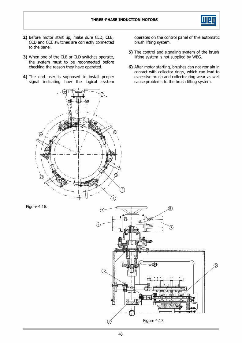
48
THREE-PHASE INDUCTION MOTORS
2) Before motor start up, make sure CLD, CLE, CCD and CCE switches are corr ectly connected to the panel.
3) When one of the CLE or CLD switches operate,
the system must to be reconnected before checking the reason they have operated.
4) The end user is supposed to install proper
signal indicating how the logical system
operates on the control panel of the automatic brush lifting system.
5) The control and signaling system of the brush
lifting system is not supplied by WEG. 6) After motor starting, brushes can not remain in
contact with collector rings, which can lead to excessive brush and collector ring wear as well cause problems to the brush lifting system.
Figure 4.16.
Figure 4.17.

49
THREE-PHASE INDUCTION MOTORS
4.6.4. ASSEMBLY 4.6.4.1. BRUSH HOLDER LIFTING DEVICE 1. Fix the pin support disc with the lifting set fixer
on the protection box of the brush holder set.
2. Mount the bearing in the support pin and fi x with a fixing pin which must be fi xed with a retaining ring.
3. Fix the bearing support pin on the support
disc. NOTE: Bearing of the support pin: 6305 2ZRS1.
Figure 4.18.

50
THREE-PHASE INDUCTION MOTORS
4.6.4.2. SHORT-CIRCUIT BUSHING MOVEMENT SET 1. Mount the roll on the roll bearing on short
bushing movement lever, and then the bearings, the spacing bushing and fix the bearing cover.
2. Fix the upper pins on one of the movement
levers.
3. Mount the support pin on the movement lever. 4. Fix the guide support on the support base and
the movement lever on the support. The rolls must be aligved with the short circuit bushing in such way that both touch the bushing simultaneously.
NOTE: Bearing of the movement levers: 6003Z.
Figure 4.19.

51
THREE-PHASE INDUCTION MOTORS
4.6.4.3. BRUSH HOLDER OPERATION SET 1. Mount the bearing on the shaft and fix it with
retaining rings. Then put a retaining ring to hold the second bearing. After that, mount it with retaining ring.
2. Mount and fix the disc on the operation shaft. 3. Insert the operation shaft in the set flange. 4. Fix the lifting disc on the operation shaft. 5. Mount the bushing on the lever operation shaft
and fix it with a retaining ring. Fix the shaft on the operation disc.
Figure 4.20.
6. Fix the locking device cover on the electromechanical device and then fix it to the device frame.
7. Fix the operation set on the brush holder
protection box. NOTE: 1) The operation shaft must be f itted between
the upper pins of the lifting lever. 2) All the parts touching mechanically must be
lubricated. After 6 months of use, check the lubrication of such parts.

52
THREE-PHASE INDUCTION MOTORS
4.6.4.4. RETURN PIN SET 1. Mount the spring shaft on the shaft support.
Mount the shaft guide washer; fit it on the shaft and lock it on the shaft and lock it with a nut.
2. Close the set with an external fixing ring and fix on the brush holder protection box.
Figure 4.21. 4.6.4.5. BRUSH HOLDER SET 1. Fix the brushes on the brush holder. Fix the
isolated pins on the support; mount the isolated discs, brush holders and contact rings on the pins.
2. Adjust the curvature ray existing on the
brushes with the collector rings and put a sandpaper between brush and ring. The sandpaper must be moved back and forth in order to make a better fitting of the brush ray with the ring ray. Unfasten the brush holder fixing bolt and turn the brush holder clockwise until the brush ray matches perfectly the ring.
Figure 4.22. – Brushes lifted.
Figure 4.23. – Position Non Short-circuited. Figure 4.24. – Position Short-circuited. Figure 4.25. – Brushes Lovered.

53
THREE-PHASE INDUCTION MOTORS
4.6.5. DISASSEMBLY For the disassembly of the liftable brush holder, proceed in the reserve way in relation to assembly procedures. 4.6.6. ADJUSTMENT OF THE BRUSH LIFTING SYSTEM 1. Turn the lifting disc up to the short-circuit
position and then turn it a bit more to release the rolls to avoid unnecessary thrusts on the roller bearings.
2. Fasten the adjusting bolt up to the backstop
disc and then lock the adjusting bolt. 3. Turn the lifting disc up to the position of non
short-circuit (brushes lowered) and repeat the same procedure carried out for the short circuit position.
44..77.. DDRRYYIINNGG OOFF TTHHEE WWIINNDDIINNGGSS It is recommended that this task be undertaken carefully and by qualified personnel. The rate of temperature rise should not exceed 5ºC per hour and the winding should not be heated up to more than 150ºC. Excessive temperature as well as too quick temperature rise can generate steams which damage the windings. During the drying process, the temperature should be controlled carefully and the insulation resistance should be measured at regular intervals. In the beginning, the insulation resistance will decrease due to the temperature increase, but it will increase during the drying process. The drying process should be continued until successive measurements of the insulation resistance show a constant insulation resistance which should be higher than the minimum value specified, as indicated in item 2.3.3. It is important to provide a good ventilation inside the motor during the drying process assuring that the moisture is removed effectively.
44..88.. DDEESSMMAANNTTLLIINNGG AANNDD RREEAASSSSEEMMBBLLYY 4.8.1. " MASTER" LINE A) SQUIRREL-CAGE ROTOR: Drive-End: 1. Remove the heat exchanger (if any). 2. Remove the temperature detectors fr om the
bearing (if any). 3. Unscrew the bolts which fasten the bearing
assembly. 4. Remove the external bearing caps (for r oller
bearing motors). 4.1. For ball bearing motors, follow the procedures described in item 4.2.2.2.
5. Unscrew the bolts of the endshield. After being removed, the bolts should be scr ewed endshields in order to force its removing. To prevent the rotor falling onto the rotor, provide a support for it.
6. Remove the bearing(s) (for roller bearing motors).
7. Remove the internal bearing cap (for r oller bearing motors).
Non Drive-End 1. Unscrew the protecting screen of the fan
(enclosed motors). 2. Remove the fan by unscrewing the bolts which
fasten it on the shaft. 3. Loosen the four nuts which fasten the fan
cover and remove it. 4. Repeat the procedures 2 to 7 of pr evious
paragraph. B) SLIP RING MOTORS: Drive-End: The procedures are the same as for squirrel cage rotor motors. Non Drive-End: 1. Remove the back protecting cover of the brush
holders. 2. Disconnect the cables from the collector ring .
Dismantle the brush holders. 3. Unscrew the brush holder protecting box from
the cooling box. 4. Remove the collector rings and the ventilating. 5. Repeat the procedures 2 to 4 of the "Non
drive-end" for squirrel cage rotor motors.

54
THREE-PHASE INDUCTION MOTORS
4.8.1.1. ROTOR REMOVING Remove the rotor from the inside of the stator by means of hoisting ropes or other devices. The device must avoid that the rotor rubs on the stator or on the coil heads. 4.8.2. A LINE Drive-End: 1. Disconnect the space heater leads from the
terminal boxes. 2. Remove the bearing temperature detectors (if
any). 3. Unscrew the bolts of the bearing assembly. 4. Remove the external bearing caps (for roller
bearing motors). 4.1. For ball bearing motors, follow the
procedures described in item 4.2.2.2. 5. Unscrew the end-shield. By using an
appropriate tool, force the end-shield to release and at the same time turn it to help the removal. Make sure that the shaft is held on a plate and so an eventual fall of the rotor on the stator is avoided.
6. Remove the bearing(s) (for roller bearing motors).
7. Remove the internal bearing cap. Non Drive-End: 1. Remove the fan cover. 2. Release the fan retaining ring. 3. Repeat the procedures from 2 to 7 of item
4.8.2 (A). NOTE: 1. For removing of rotor, observe section 4.8.1.1. 2. It is not necessary to remove the stator from
the frame to perform an eventual rewinding. 4.8.3. F LINE Drive-End: Drand A and H lines. Non Drive-End: 1. Repeat the procedures 1 to 3 of item 4.8.2 (B). 2. Remove back protecting cover of the brush
holder. 3. Disconnect the cables from the collector ring. 4. Remove the brushes and dismantle the brush-
holder.

55
THREE-PHASE INDUCTION MOTORS
4.8.4. H LINE
Figure 4.26. Pos. Description Pos Description 1 Frame 15 Internal fan 2 Grounding lug 16 Internal non drive end bearing cap 3 Shaft 17 Non drive-end space heater 4 Drive-end grease valve 18 Non drive cover 5 External drive end bearing cap 19 Non drive end bearing temperature sensor 6 Drive end bearing 20 Non drive end bearing 7 Internal drive end bearing cap 21 Non drive-end grease valve 8 Drive end bearing temperature sensor 22 External non drive end bearing cap 9 Drive end cover 23 Accessory connection box 10 Drive-end space heater 24 Stator connection box 11 Complete rotor assembly 25 External fan 12 Stator lamination core 26 Fan cover 13 Stator temperature sensor 27 Non driv e end bearing grease fitting 14 Stator fixing pin 28 Drive end bearing grease fitting Tables 4.5.
Safety! Ensure that the power cables have been switched-off.
DISASSEMBLY 1) Disconnect the temperature sensor cables (pos. 8
and 19) of the accessory connection box terminals;
2) Remove the non drive end fan cover (pos. 26); 3) Unfasten the fixing ring of the external non drive
end bearing cap and remove the fan (pos.25); 4) Unfasten the bolts that fix the external non drive
end bearing caps; 5) Remove the external drive end and non drive end
bearing caps (pos. 5 and 22); 6) Remove the drive end and non drive end grease
valve (pos. 4 and 21), unfastening the bolts that fix them to the shaft;
7) Place supports underneath the shaft to avoid that the rotor falls on the stator;
8) Unfasten and remove the drive end and non drive end covers (pos.9 and 18);
9) Remove drive end and non drive end bear ings (pos.6 and 20) with the application of proper device;
10) Remove the internal drive end and non drive end bearing caps (pos. 7 and 16);
11) Applying proper device, remove the rotor (pos. 11) from the stator through the non drive end side of the motor, and pay attention to avoid that the rotor rubs the stator or on coil heads.
ASSEMBLY 1) Applying proper device, fit the rotor (pos. 11)
into the stator, from the non drive end side of the motor, and pay attention to avoid that the rotor rubs on the stator or on the coil heads;
2) Place the internal bearing caps; 3) Fill out with grease ¾ the compartment of the
internal bearing caps and bearings (check type of grease on the bearing identification nameplate attached to motor covers);
4) Check carefully shaft and cover surfaces where bearings will be fitted so as to avoid scratches or knocks. Also check for correct mechanical dimension tolerances;
5) Heat up and mount the drive end and non drive end bearings (pos. 6 and 20);
6) Lift the rotor, place supports underneath the shaft and mount drive end and non drive end covers (pos.9 and 18);
7) Mount the drive end and non drive end grease valve (pos. 4 and 21) and fix them to the shaft;
8) Mount the external drive end and non drive end bearing caps (pos. 5 and 22), fixing them t the internal bearing caps (pos. 7 and 16);
9) Mount the external non drive end fan (pos. 25) fixing it with a retaining ring;
10) Mount the non drive end fan cover (pos. 26); 11) Connect the temperature sensor cables (pos. 8
and 19) to the accessory connection box terminals;
12) Fill in remaining grease through the drive end and non drive end grease fitting (pos. 27 and 28).

56
THREE-PHASE INDUCTION MOTORS
4.8.5. TIGHTENING TORQUES FOR SCREWS The table below presents the tightening torques of the screws recommended for assembly of the motor or its parts:
Resistance Class 4.6 5.8 8.8 12.9
Diameter Tightening torque (Nm) tolerance ±10%
M6 1.9 3.2 5.1 8.7 M8 4.6 7.7 12.5 21
M10 9.1 15 25 41 M12 16 27 42 70 M16 40 65 100 175 M20 75 125 200 340 M24 130 220 350 590
Notes: - The resistance class normally is marked in the
head of the hexagonal screws. - When do not have marking at screws,
indicates that the resistance class is 4.6. - The internal hexagonal screws (type Allen)
possess resistance class 12.9. 44..99.. GGEENNEERRAALL AADDVVIICCEESS - Any damaged part (cracked, or distorted
machined parts, damaged threads) should be replaced and never recovered.
- All services herewith described should be undertaken by qualified personnel in order not to damage the equipment. In case of further doubts, contact WEG Máquinas.

57
THREE-PHASE INDUCTION MOTORS
44..1100.. MMAAIINNTTEENNAANNCCEE SSCCHHEEDDUULLEE
COMPONENT DAILY WEEKLY EVERY 3 MONTHS
YEARLY (PARTIAL
MAINTEN.)
EVERY 3 YEARS (COMPLETE MAINTEN.)
- Complete motor. - Check the noise
and the vibration levels.
- Drain condensed water (it any).
- Retighten the bolts.
- Dismantle the motor. Check spare parts.
- Winding of the stator and rotor.
- Visual inspection. Measure insulation resistance.
- Cleanliness: check the fastenings and the slot wedges; measure the insulation resistance.
- Bearings. - Check the noise level.
- Regrease; for intervals see the greasing plate.
- Vibration control.
- Clean the bearings. Replace them, if required, check bearing liner and replace it, if required (sleeve bearing) check sleeve race (shaft) and rebuild, if required.
- Terminal boxes and grounding lugs.
- Clean the inside
area retighten the bolts.
- Clean the inside area retighten the bolts.
- Coupling: follow the maintenance instructions contained in the manual of the coupling manufacturer.
- After the first week of operation: check the alignment and fastening.
- Check alignment and fastening.
- Check alignment and fastening.
- Monitoring devices.
- Record the measurement values.
- If possible, disassemble
and check its operating condition.
- Filter. - Clean it, if required.
- Clean it, if required.
- Clean it (see section 4.1.2).
- Slip rings area. - Inspect the
cleanliness and clean it, if required.
- Check the cleanliness and clean it, if required.
- Slip rings. - Check surface and contact area.
- Brushes (slip ring motors);
- Shaft grounding brushes (if any).
- Check and replace them when 2/3 of their height is worn (check wear mark in fig. 4.5).
- Air/air heat exchanger. - Clean the pipes of the
heat exchanger.
Table 4.6.

58
THREE-PHASE INDUCTION MOTORS
5. SPARE PARTS 55..11.. HHOOWW TTOO OORRDDEERR When ordering spare parts, motor type and serial number must be always given as indicated on the nameplate or on the frame. 55..22.. KKEEEEPPIINNGG SSTTOOCCKK It is recommended to keep in stock the spare parts that, under normal use, can have some kind of wear such as: - Set of bearings; - Brushes (type and quantity according to the
specification); - Felts for filter (if any). The spare parts must be stored in clean, dry environments and aired well, if possible, with constant temperature. The bearing liners also are spare parts, however, due to the high cost, we suggest to analyze the real necessity to keep these parts in stock.

59
THREE-PHASE INDUCTION MOTORS
6. ABNORMAL SITUATIONS DURING OPERATION The majority of the abnormal situations during operation that affect the running of electric motors can be avoided by a predictive maintenance. Sufficient ventilation, cleanliness and careful maintenance are the main factors. A further essential factor is the prompt attention to any abnormal situation such as vibrations, shaft knocks, declining insulation resistance, smoke or fire, sparking or unusual slip ring or brush wear, sudden changes of bearing temperature. When failures of an electric or mechanical nature arise, the first step to be taken is to stop the motor and perform a subsequent examination of all mechanical and electrical parts of the installation. In the event of having a fire, the motor should be disconnected from the power supply, which is normally done by turning off the respective switches. In case of starting of fire inside the motor itself, steps should be taken to retrain and suffocate it by covering the ventilation openings. To extinguish a fire, dry chemical or CO² extinguishers should be used. Never use water. 66..11.. CCOOMMMMOONN FFAAIILLUURREESS OONN IINNDDUUCCTTIIOONN MMOOTTOORRSS Motors built by WEG Máquinas are normally designed for Class F insulation (155ºC) and for ambient temperatures up to 40ºC(as indicated on the motor nameplate). Most winding failures occur when temperature limits, due to current overload, are surpassed throughout the winding or even in only portions thereof. These failures are identified by the darkening or carbonizing of the wire insulation. 6.1.1. SHORT-CIRCUIT BETWEEN TURNS A short-circuit between turns can be a consequence of two coincident insulation defects, or the result of defects arising simultaneously on two adjacent wires. In some cases, the three-phase current imbalance can be so insignificant that the motor protective device fails to react. A short circuit between turns, and phases to ground due to insulation failure is rare, and even so, it normally occurs during the early stages of operation.
6.1.2. WINDING FAILURES a) ONE WINDING PHASE BURNT This failure occurs when a motor runs wired in delta and current fails in one power supply conductor. Current rises from 2 to 2.5 times in the remaining winding with a simultaneous drop of speed. If the motor stops, the current will increase from 3.5 to 4 times its rated value. In most cases, this defect is due to lack of a protective switch, or because this switch has been set too high. b) TWO WINDING PHASES BURNT This failure occurs when current fails in one power supply conductor and the motor winding is star-connected. One of the winding phases remains current less while the other absorb the voltage and carries an excessive current. The slip almost doubles. c) THREE WINDING PHASES BURNT Probable cause 1: Motor protected only by fuses. An overload on the motor will be the cause of the trouble. As a consequence, progressive carbonizing of the wires and insulation will generate a short between turns, or a short against the frame. A protective switch placed before the motor would easily solve this problem. Probable cause 2: Motor incorrectly connected. For example: a motor with windings designed for 220/380V is connected through a stat-delta switch of 380V. The drawn current will be so high that the winding will burn out in a few seconds if the fuses or a protective switch incorrectly set fail to react promptly.
60
THREE-PHASE INDUCTION MOTORS
Probable cause 3: The star-delta switch is not commutated and the motor continues to run for a certain time connected to the star under overload conditions. As it only develops 1/3 of its torque, the motor cannot reach rated speed. The increase of slip results in higher ohmic losses arising from the Joule effect. As the stator current, consistent with the load, may not exceed the rated value for delta connection, the protective switch will not react. Consequent to increased winding and motor losses the motor will overheat and the winding will burn out. Probable cause 4: Failures from this cause are caused by thermal overload, due to excessive starts under intermittent operation or to an overly long starting cycle. The perfect functioning of motors operating under these conditions is only assured when the following values are taken into account. a) Number of starts per hour; b) starting with or without load; c) Mechanical brake or current inversion; d) Acceleration of load connected to motor shaft; e) Load torque related to speed during
acceleration and braking. The continuous effort withstood by the higher rotor during intermittent starting brings about losses which provoke overheating. Under certain circumstances, there is a possibility that the stator winding be subject to damage with the motor stopped as a result of the heating on the motor. 6.1.3. ROTOR FAILURES (SQUIRREL CAGE) If a motor running under load conditions produces a noises of varied intensity and decreasing frequency while the load is increased, the reason, in most cases, will be an unsymmetrical rotor winding. In squirrel-cage motors the cause will nearly always be a break in one or more of the rotor bars; simultaneously, periodical stator current fluctuations may be recorded.
As a rule, this defect appears only in molded or die cast aluminum cages. Failures due to spot heating in one or another of the bars in the rotor care are identified by blue coloration at the affected points. If there are failures in various contiguous bars, vibrations and shuddering can occur. When the rotor core gets a blue or violet coloration, it is a sign of overloading. This can be caused by overly high slip, by too many starts or overlong starting cycles. This failure can also come from insufficient power supply voltage. 6.1.4. SLIP RING ROTOR FAILURES A break in one phase of the rotor winding is noticed by a strong noise that varies according to the slip and, in addition, stronger periodical stator current fluctuations occur. It is possible, but rarely so, that a rupture could have occurred in the connection between the winding and the slip ring. However, it is advisable to first check if there is a break in the rheostat starter connection, or even in the part itself. 6.1.5. SHORT BETWEEN TURNS ON SLIP RING MOTORS This abnormal situation occurs only under extremely rare circumstances. Depending on the magnitude of the short circuit, the start can be violent even if the rheostat is at the first tap of its starting position. In this case, heavy starting currents are not carried through the rings and so no burn marks will be noticed on them. 6.1.6. BEARING FAILURES Bearing failure are the most frequent causes for delayed breakdowns. The most common reasons for this failure are identified as excessive vibration, inc orrect operation, bad alignment, unbalanced couplings and excessive radial and/or axial loads. Check item 4.2 for bearing maintenance.

61
THREE-PHASE INDUCTION MOTORS
6.1.7. SHAFT BREAKING Although bearings traditionally constitute the weakest part and the shafts are designed with wide safety margins, it is possible that a shaft may break by fatigue from bending stress caused by excessive belt tension. In most cases, breaking occurs right behind the drive end bearing. As a consequence of alternating bending stress induced by a rotating shaft, breaking travel inwards from the outside of the shaft until the point of rupture is reached when resistance of the remaining shaft cross-section no longer suffices. At this point, avoid additional drilling on the shaft (fastening screw holes) as such operations tend to cause stress concentration. The replacement of only one or two belts of a belt drive system is frequently a cause of shaft breaking, besides being an incorrect practice. Any used and consequently stretched belts on a drive system, especially those closer to the motor, while new and unstretched belts are placed on the same drive but farther from the bearing, can cause shaft stress. 6.1.8. DAMAGE ARISING FROM POORLY FITTED TRANSMISSION PARTS OR IMPROPER MOTOR ALIGNMENT Damaged to bearing and breaking of shafts are often resulted from inadequate fitting of pulley, couplings or pinions on the shaft. These parts "knock" when rotating. The defect can be recognized by the scratches that appear on the shaft or the eventual scale like flaking of the shaft end. Keyways with edges pitted by loosely fitted keys can also cause shaft failures. Poorly aligned couplings cause knocks and radial and axial shaking to shaft and bearings. Within a short while, these bad practices cause the deterioration of the bearings and the enlargement of the bearing on the drive end side. In other cases, motor shaft can break.

62
THREE-PHASE INDUCTION MOTORS
66..22.. AABBNNOORRMMAALL SSIITTUUAATTIIOONNSS DDUURRIINNGG OOPPEERRAATTIIOONN NOTE: The following chart presents a list of abnormal situations during motor operation, the probable cause for such abnormal situations, and the corrective measures. In case of further doubts, contact Weg Máquinas.
ABNORMAL SITUATION PROBABLE CAUSE(S) CORRECTIVE MEASURE(S)
- Motor fails to start, neither coupled, nor uncoupled.
- At least two feeding conductors are broken, no voltage supply.
- The rotor is locked. - Brushes problem. - Bearing is damaged.
- Check commanding board, switch, fuses, power supply conductors, terminals and setting of brushes.
- The brushes might be worn or set incorrectly.
- Replace the bearing.
- Motor starts very slowly with load and does not reach rated speed.
- Motor starts under no load, but is fails when the load is applied .
- Too high load during start. - Supply voltage too low. - Too high voltage drop on the feeding
conductors. - Rotor bars damaged or interrupted. - One supply conductor remained
interrupted after the starting.
- Do not apply load on the machine during start.
- Measure supply voltage, set the correct value.
- Check the cross section of the feeding conductors.
- Check and repair the rotor winding (squirrel cage), test the short circuit device (slip ring).
- Check the supply conductors.
- Stator current changes with double frequency of the slip; during start humming can be heard.
- Rotor winding is interrupted. - Brushes problem.
- Check and repair rotor winding and short-circuit device.
- Clean, set correctly or replace the brushes.
- No load current too high. - Supply current too high. - Measure the supply voltage and set it to the correct value.
- Rapid overheating of the stator, there is a humming during the operation.
- Parallel or in phase connected wires of the stator winding are broken.
- Measure the resistance of all winding phases. Replace the stator core with the winding.
- Areas of heating on the stator winding
- Short between turns. - Interruption of conductors connected in
parallel or in phase of the stator winding - Poor connection.
- Rewind the motor. - Remake the connections.
- Areas of heating on the rotor. - Interruption in the rotor winding. - Repair the rotor winding, or replace it
- Abnormal noise with motor connected to load.
- Mechanical problems. - Electric problems.
- Noise decreases generally with the speed drop; see also "Noisy operation when uncoupled"
- Noise disappears when motor is switched on. Contact the manufacturer
- Noise occurs when coupled and disappears when not coupled.
- Failure in the drive components, or on the driven machine.
- Failure on the gearing. - Coupling problem. - Foundation is sunk. - Poor balancing of the parts or of the
driven machine. - Supply voltage too high. - Direction of rotation is not correct.
- Check the power transmission, coupling and alignment.
- Align the driving, check the position (coupling) of the gearing.
- Align the motor and the driven machine. - Repair the foundation. - Test the supply voltage and the noload
current. - Reverse the connections of two phases. - Rebalance the unit.

63
THREE-PHASE INDUCTION MOTORS
ABNORMAL SITUATION PROBABLE CAUSE(S) CORRECTIVE MEASURE(S)
- Overheating of the stator winding with load.
- Poor cooling due to dirty air tubes. - Load too high. - Excessive number of starts, or the
inertia is too high. - Voltage too high and consequently also
the iron losses are too high. - The voltage is too low and consequently
the current is too high. - One feeding conductor is interrupted, or
one phase of the winding is interrupted. - Rotor is rubbing on the stator. - The operation mode does not
correspond to the data on the nameplate.
- Electrical load unbalanced (blown fuse, incorrect control).
- Dirty windings. - Obstructed cooling system. - Dirty filter. - Rotation direction not compatible with
the fan used.
- Clean the air tubes of the cooling system.
- Measure the stator voltage, decrease the load, use a larger motor.
- Reduce the number of starts. - Do not exceed more than 110% the
rated voltage, unless specifications on the nameplate are different.
- Check the voltage supply and the voltage drop.
- Check the current in all phases and make correction.
- Check air gap, operation conditions, bearings, vibrations.
- Maintain the operation mode as specified on the nameplate, or reduce the load.
- Verify if there are unbalanced voltages, or if the two phases are operating.
- Clean. - Clean the felt of the filter. - Analyze the fan in relation to motor
rotation direction.
- Noisy operation when uncoupled.
- Unbalancing. - One phase of the stator winding is
interrupted. - Dirt in the air gap. - Fastening bolts are loose. - Unbalancing of the rotor increase after
the assembling of the driving components. Unbalanced rotor.
- Foundation resonance. - Motor frame is deformed. - Bent shaft. - Uneven air gap.
- Noisy operation continues during rundown time after switching off the voltage; rebalance the motor.
- Test current input of all feeding conductors.
- Remove the dirt and clean the air gap. - Tighten and block bolts. - Check balancing. - Level the foundation. - Check the alignment. - The shaft can be bent, check the
balancing and the eccentricity of the rotor.
- Check if the shaft is bent or if the bearings are damaged.
- Slip ring motor operating at low speed with external resistance disconnected.
- Control circuit conductors too light. - Open circuit on rotor circuits. - Dirt between brush and slip ring. - Brushes gripe on brush holders. - Incorrect pressure on brushes. - Rough surfaces on slip rings. - Eccentric rings. - High current density on brushes. - Brushes incorrectly set.
- Install heavier conductors on control circuit.
- Bring control closer to motor. - Test circuit with a magneto, or other
means, and undertake necessary repairs.
- Clean slip rings and insulation assembly. - Select brushes of correct size. - Check pressure on each brush and
adjust it accordingly. - Clean, sand and polish. - Machine on lathe or with portable tool
without removing from machine. - Reduce load or replace brushes. - Reset brushes correctly.
- Brush sparking.
- Poorly set brushes with insufficient pressure.
- Overload. - Slip rings in poor condition. - Oval slip rings. - Excess of vibration. Rough surfaces and
scored rings. - Low load causing damage to slip rings.
- Check brush setting, adjust for correct pressure.
- Reduce load or install motor with higher capacity.
- Clean rings and reset brushes. - Polish the slip rings and machine the
same on lathe. - Balance the rotor, check the brushes for
free movement within holders. - Check origin of vibration and correct it. - Adjust the brushes to the actual load
requirement and machine the slip rings.
Table 6.2.

64
THREE-PHASE INDUCTION MOTORS
66..33.. AABBNNOORRMMAALL BBEEAARRIINNGG SSIITTUUAATTIIOONNSS AANNDD FFAAIILLUURREESS DDUURRIINNGG OOPPEERRAATTIIOONN NOTE: The following chart presents abnormal bearing situations and failures during motor operation, the probable cause for such abnormal situation and the corrective measures. In certain cases, bearing manufacturer must be contacted to find out the cause of the failure.
ABNORMAL SITUATION POSSIBLE CAUSE(S) CORRECTIVE MEASURE(S) - The motor "snores" during operation. - Damaged bearings. - Replace the bearing.
- Bearing noisy, dull spots, grooves in the ball races. - Bearing was slanting mounted. - Align the bearing and machine the
bearing seat.
- High bearing noise and a high overheating of the bearing.
- Cage corrosion, small chips in the grease, race failure due to insufficient grease, or inadequate clearance.
- Clean and replace the grease according to the specifications. Replace the bearing.
- Overheating of bearings.
- Excessive grease. - Excessive axial or radial strain on belt. - Bent shaft. - Lack of grease. - Hardened grease cause locking on balls. - Foreign material in the grease.
- Remove the grease relief and run the motor until excess grease is expelled.
- Reduce belt tension. - Have shaft straightened and check rotor
balance. - Add grease to bearing. - Replace bearing. - Flush out housing and lubricant; regress.
- Dark spots on one side of the ball races subsequently the formation of grooves. - Excessive axial strength. - Check the condition between coupling
and driving.
- Dark lines on the ball races or very close transversal grooves. - Current on the bearings.
- Clean and replace the bearing insulation. Install an insulation if there was not any.
- Branch the current avoiding that it circulates through the bearing.
- Grooves in the races and depressions in the division of the cylindrical elements.
- External vibration, mainly when the motor stopped for a long period of time.
- Lack of maintenance during storage.
- If the motor is stopped during a long period, turn the shaft to an other position from time to time. This is mainly required for spare motors.
Table 6.3.
IMPORTANT:
The motors listed in this manual are constantly updated. For this reason, the information here with included may change without prior notice.

65
THREE-PHASE INDUCTION MOTORS
7. WARRANTY TERMS FOR ENGINEERING PRODUCTS These products, when operated under the conditions stipulated by WEG in the operating manual for such product, are warranted against defects in workmanship and materials for twelve (12) months from startup date or eighteen (18) months from manufacturer shipment date, whichever occurs first. However, this warranty does not apply to any product which has been subject to misuse, misapplication, neglect (including without limitation, inadequate maintenance, accident, improper installation, modification, adjustment, repair or any other cases originated from inadequate applications). The company will neither be responsible for any expenses incurred in installation, removal from service, consequential expenses such as financial losses nor transportation costs as well as tickets and accommodation expenses of a technician when this is requested by the customer. The repair and/or replacement of parts or components, when effectuated by WEG within the Warranty period do not give Warranty extension, unless otherwise expressed in writing by Weg. This constitutes WEG's only warranty in connection with this sale and is in lieu of all other warranties, expressed or implied, written or oral. There are no implied warranties of merchantability or fitness for a particular purpose that apply to this sale. No employee, agent, dealer, repair shop or other person is authorized to give any warranties on behalf of WEG nor to assume for WEG any other liability in connection with any of its products. In case this happens without Weg's authorization, Warranty is automatically cancelled. LIABILITY Except as specified in the foregoing paragraph entitled "Warranty Terms for Engineering Products", the company shall have no obligation or liability whatsoever to the purchaser, including, without limitation, any claims for consequential damages or labor costs, by reason of any breach of the express warranty described therein. The purchaser further hereby agrees to indemnify and hold the company harmless from any causes of action (other than cost of replacing or repairing the defective product as specified in the foregoing paragraph entitled "Warranty Terms for Engineering Products"), arising directly or indirectly from the acts, omissions or negligence of the purchaser in connection with or arising out of the testing, use, operation, replacement or repair of any product described in this quotation and sold or furnished by the company to the purchaser.
WEG INDÚSTRIAS S.A. - MÁQUINAS Av. Pref. Waldemar Grubba, 3000 89256900 Jaraguá do Sul/SC BRAZIL
Phone: (55) 047 372 4000 Fax: (55) 047 372 4030 São Paulo: Phone: (55) 011 5053 2300 Fax: (55) 011 5052 4202
www.weg.com.br
1013.02/0295