Installation and Maintenance Manual for Orbit Spring...
99
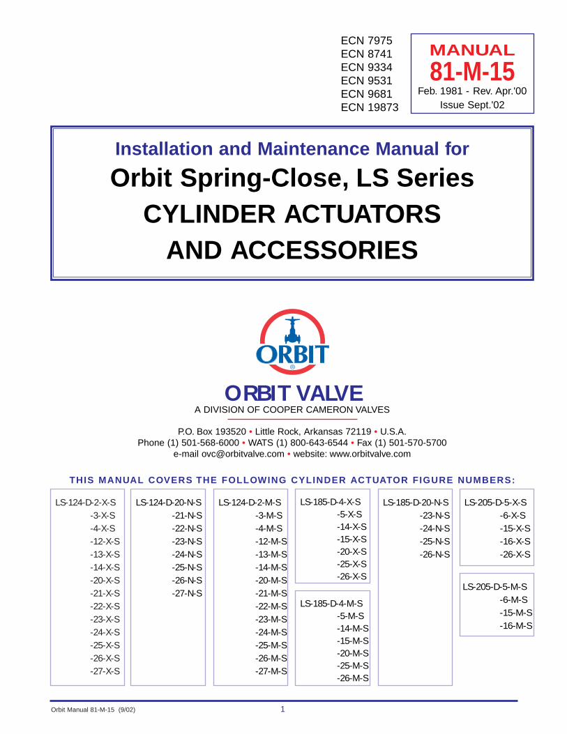
Orbit Manual 81-M-15 (9/02) 1 Installation and Maintenance Manual for Orbit Spring-Close, LS Series CYLINDER ACTUATORS AND ACCESSORIES MANUAL 81-M-15 Feb. 1981 - Rev. Apr.'00 Issue Sept.'02 ORBIT VALVE A DIVISION OF COOPER CAMERON VALVES P.O. Box 193520 • Little Rock, Arkansas 72119 • U.S.A. Phone (1) 501-568-6000 • WATS (1) 800-643-6544 • Fax (1) 501-570-5700 e-mail [email protected] • website: www.orbitvalve.com ECN 7975 ECN 8741 ECN 9334 ECN 9531 ECN 9681 ECN 19873 LS-124-D-2-X-S -3-X-S -4-X-S -12-X-S -13-X-S -14-X-S -20-X-S -21-X-S -22-X-S -23-X-S -24-X-S -25-X-S -26-X-S -27-X-S LS-124-D-20-N-S -21-N-S -22-N-S -23-N-S -24-N-S -25-N-S -26-N-S -27-N-S LS-124-D-2-M-S -3-M-S -4-M-S -12-M-S -13-M-S -14-M-S -20-M-S -21-M-S -22-M-S -23-M-S -24-M-S -25-M-S -26-M-S -27-M-S LS-185-D-4-X-S -5-X-S -14-X-S -15-X-S -20-X-S -25-X-S -26-X-S LS-185-D-20-N-S -23-N-S -24-N-S -25-N-S -26-N-S LS-205-D-5-X-S -6-X-S -15-X-S -16-X-S -26-X-S THIS MANUAL COVERS THE FOLLOWING CYLINDER ACTUATOR FIGURE NUMBERS: LS-185-D-4-M-S -5-M-S -14-M-S -15-M-S -20-M-S -25-M-S -26-M-S LS-205-D-5-M-S -6-M-S -15-M-S -16-M-S
Transcript of Installation and Maintenance Manual for Orbit Spring...
Orbit Manual 81-M-15 (9/02) 1
Installation and Maintenance Manual for
Orbit Spring-Close, LS Series CYLINDER ACTUATORS
AND ACCESSORIES
MANUAL
81-M-15Feb. 1981 - Rev. Apr.'00
Issue Sept.'02
ORBIT VALVEA DIVISION OF COOPER CAMERON VALVES
P.O. Box 193520 • Little Rock, Arkansas 72119 • U.S.A.Phone (1) 501-568-6000 • WATS (1) 800-643-6544 • Fax (1) 501-570-5700
e-mail [email protected] • website: www.orbitvalve.com
ECN 7975ECN 8741ECN 9334ECN 9531ECN 9681ECN 19873
LS-124-D-2-X-S-3-X-S-4-X-S-12-X-S-13-X-S-14-X-S-20-X-S-21-X-S-22-X-S-23-X-S-24-X-S-25-X-S-26-X-S-27-X-S
LS-124-D-20-N-S-21-N-S-22-N-S-23-N-S-24-N-S-25-N-S-26-N-S-27-N-S
LS-124-D-2-M-S-3-M-S-4-M-S-12-M-S-13-M-S-14-M-S-20-M-S-21-M-S-22-M-S-23-M-S-24-M-S-25-M-S-26-M-S-27-M-S
LS-185-D-4-X-S-5-X-S-14-X-S-15-X-S-20-X-S-25-X-S-26-X-S
LS-185-D-20-N-S-23-N-S-24-N-S-25-N-S-26-N-S
LS-205-D-5-X-S-6-X-S-15-X-S-16-X-S-26-X-S
THIS MANUAL COVERS THE FOLLOWING CYLINDER ACTUATOR FIGURE NUMBERS:
LS-185-D-4-M-S-5-M-S-14-M-S-15-M-S-20-M-S-25-M-S-26-M-S
LS-205-D-5-M-S-6-M-S-15-M-S-16-M-S

2 Orbit Manual 81-M-15 (9/02)
Cylinder Actuator Identification.......................................................................................3Operation of Spring-Close Actuators..............................................................................4Optional Two-Way Manual Mechanism ..........................................................................5
INSTALLATIONInstallation of Actuator/Valve Combination .....................................................................7Actuator Operating Parameter Chart ..............................................................................9Conversion of Handwheel Operated Valves to Actuator Operated ValvesValve Model Identification .............................................................................................11Actuator Mounting on “L” Valves Valve Model Identification .............................................................................................11Indicator Plates (Installation & Adjustment)..................................................................52Nominal Valve Stroke Chart .........................................................................................53Spring Compression Adjustment ..................................................................................54
ACTUATOR REPAIRActuator Removal From Valve .....................................................................................57Gas-Over-Oil Tank and Piping Removal & Installation ................................................59Disassembly of Spring-Close Actuator (LS-124, LS-185, LS-205) ..............................63Assembly Of Spring-Close Actuator (LS-124, LS-185, LS-205) ..................................68Disassembly of Spring-Close Actuator with Two-Way Mechanism (LS-124, LS-185) ........72Assembly Of Spring-Close Actuator with Two-Way Mechanism (LS-124, LS-185) ..........78Disassembly Of Spring-Close Actuator with Two-Way Mechanism (LS-205)...................82Assembly Of Spring-Close Actuator with Two-Way Mechanism (LS-205) .......................87Actuator Conversions ..................................................................................................90
MAINTENANCELubrication Schedule ....................................................................................................91Lubrication Points ........................................................................................................91Recommended Lubricants............................................................................................92Gas-Over-Oil Tank Fluid Level ......................................................................................92
ACCESSORIESInstrumentation Panels ................................................................................................93Pressure Reserve Tank (Accumulator) .........................................................................94Electric CX Switch
Installation ...............................................................................................................95Removal ..................................................................................................................97Adjustment .............................................................................................................97
APPENDIXActuator mounting dimensions .....................................................................................98Conversion factors ........................................................................................................98
2
1
CONTENTS
An “L” Valve is an Orbit term used to define a valve which is ready for actuator attachment.(The handwheel assembly has been removed and any adapter flanges, if required, areinstalled on the valve bonnet.) The “L” does not appear as a prefix or suffix to the valve serialnumber.
Alignment tool Z-2886 is required to reassemble the actuator. Order tool when orderingreplacement parts.
2
1NOTES:
Orbit Manual 81-M-15 (9/02) 3
CYLINDER ACTUATOR IDENTIFICATION
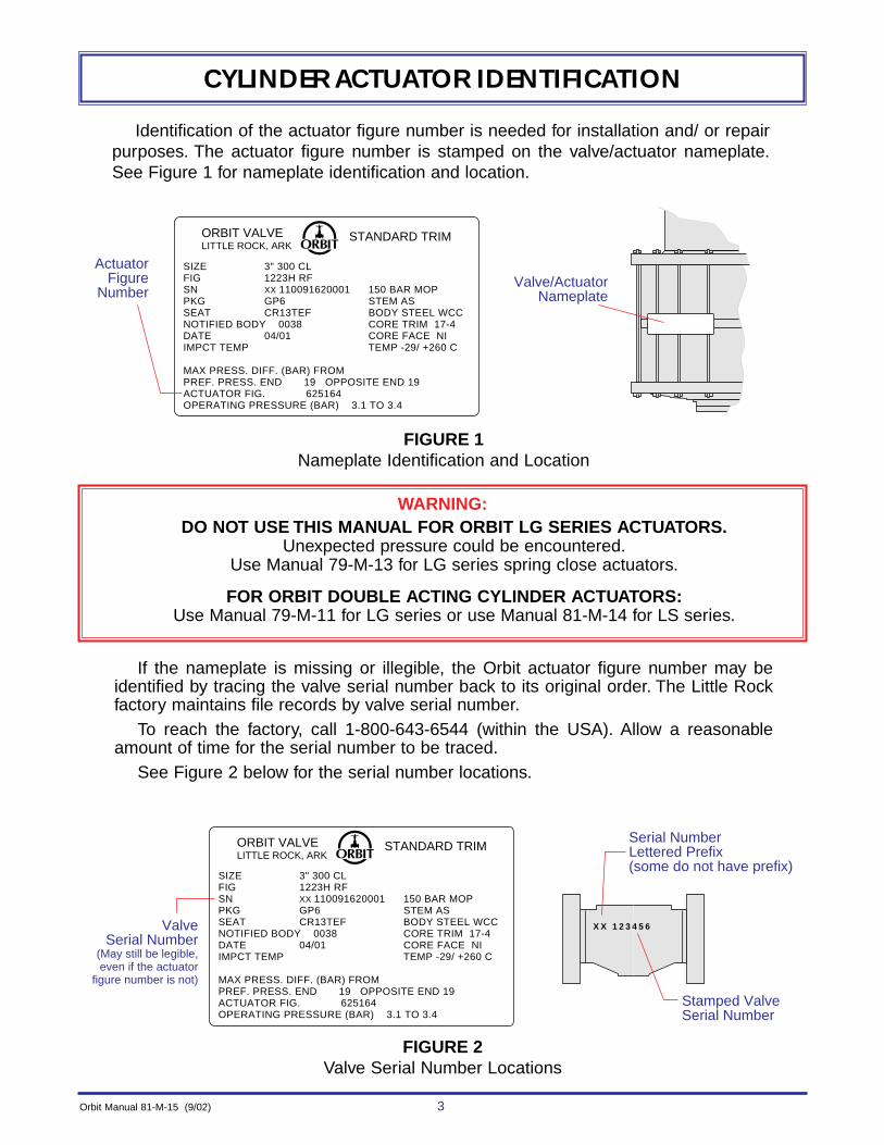
Identification of the actuator figure number is needed for installation and/ or repairpurposes. The actuator figure number is stamped on the valve/actuator nameplate.See Figure 1 for nameplate identification and location.
Valve/ActuatorNameplate
ActuatorFigure
Number
SIZE 3" 300 CLFIG 1223H RFSN XX 110091620001 150 BAR MOPPKG GP6 STEM ASSEAT CR13TEF BODY STEEL WCCNOTIFIED BODY 0038 CORE TRIM 17-4DATE 04/01 CORE FACE NIIMPCT TEMP TEMP -29/ +260 C
MAX PRESS. DIFF. (BAR) FROMPREF. PRESS. END 19 OPPOSITE END 19ACTUATOR FIG. 625164OPERATING PRESSURE (BAR) 3.1 TO 3.4
ORBIT VALVELITTLE ROCK, ARK
STANDARD TRIM
Serial Number Lettered Prefix (some do not have prefix)
Stamped ValveSerial Number
X X 1 2 3 4 5 6ValveSerial Number
(May still be legible,even if the actuator
figure number is not)
ORBIT VALVELITTLE ROCK, ARK
STANDARD TRIM
SIZE 3" 300 CLFIG 1223H RFSN XX 110091620001 150 BAR MOPPKG GP6 STEM ASSEAT CR13TEF BODY STEEL WCCNOTIFIED BODY 0038 CORE TRIM 17-4DATE 04/01 CORE FACE NIIMPCT TEMP TEMP -29/ +260 C
MAX PRESS. DIFF. (BAR) FROMPREF. PRESS. END 19 OPPOSITE END 19ACTUATOR FIG. 625164OPERATING PRESSURE (BAR) 3.1 TO 3.4
If the nameplate is missing or illegible, the Orbit actuator figure number may beidentified by tracing the valve serial number back to its original order. The Little Rockfactory maintains file records by valve serial number.
To reach the factory, call 1-800-643-6544 (within the USA). Allow a reasonableamount of time for the serial number to be traced.
See Figure 2 below for the serial number locations.
WARNING:DO NOT USE THIS MANUAL FOR ORBIT LG SERIES ACTUATORS.
Unexpected pressure could be encountered.Use Manual 79-M-13 for LG series spring close actuators.
FOR ORBIT DOUBLE ACTING CYLINDER ACTUATORS:Use Manual 79-M-11 for LG series or use Manual 81-M-14 for LS series.
FIGURE 1Nameplate Identification and Location
FIGURE 2Valve Serial Number Locations

4 Orbit Manual 81-M-15 (9/02)
OPERATION OF SPRING-CLOSE ACTUATOR
Refer to Figure 3.
The Orbit spring-close cylinder actuator is used for remote operation of Orbit valves.
Operation is accomplished by pressurizing the actuator to open the valve and de-pressurizing to close. A compression spring is used to create the force to close thevalve/actuator and gas (air) pressure working on the opening side of the actuator pistonsis used to create the force to open the valve/actuator.
WARNING:Avoid bleeding pressure from the actuator while valve is in service, unless
valve closure is desired. Loss of pressure will cause the valve to close.
Exhaust
Gas (Air) PressureTo Open
Piston
Piston
Compression SpringTo Close
Actuator Stem
Exhaust
FIGURE 3Spring-Close Cylinder Actuator Operation
OPTIONAL TWO-WAY MANUAL MECHANISM OPERATION
Refer to Figure 4.
The two-way manual mechanism is used to lock the valve in either the open or closed posi-tion, to manually open the valve if gas pressure to the actuator is lost, or to manually close thevalve if spring failure occurs.

Orbit Manual 81-M-15 (9/02) 5
OPERATION OF SPRING-CLOSE ACTUATOR, continued
LS-124 & 185 ACTUATORS (TYPE -M-)NORMAL OPERATING POSITION: Spring-to-close and gas (air) pressure to open. The bot-tom of the handwheel is adjusted so that it is just touching the top of the neutral position indi-cator gage and the jam nut is tightened against the top of the spring housing.
To MANUALLY OPEN the valve, the jam nut is loosened and the handwheel is turnedcounterclockwise until the valve is opened.To MANUALLY CLOSE the valve, the jam nut is loosened, the gas (air) pressure isbled from the actuator and the handwheel is turned clockwise , until the valve isclosed.To LOCK OPEN the valve, when the valve is open, loosen the jam nut and turn thehandwheel counterclockwise until positive resistance is met.To LOCK CLOSE the valve, when the valve is closed, loosen the jam nut and turn thehandwheel clockwise until positive resistance is met.
LS-124 & 185 ACTUATORS (TYPE -N-)
NORMAL OPERATING POSITION: Spring-to-close and gas (air) pressure to open. The lock pin isinstalled in the manual open position, as shown in the figure.
To MANUALLY OPEN the valve, the lock pin is removed and the handwheel is turnedcounterclockwise until the valve is opened.To MANUALLY CLOSE the valve, the lock pin is removed, the gas (air) pressure isbled from the actuator and the handwheel is turned clockwise until the valve isclosed.To LOCK OPEN the valve, when the valve is open, remove the lock pin and turn thehandwheel counterclockwise until positive resistance is met.To LOCK CLOSE the valve, when the valve is closed, remove the lock pin and turn thehandwheel clockwise until positive resistance is met.
LS-205 ACTUATOR
NORMAL OPERATING POSITION: Spring-to-close and gas (air) pressure to open. Thehandwheel is adjusted so the indicator rod is even with the neutral position indicator.
To MANUALLY OPEN the valve, the handwheel is turned counterclockwise until thevalve opens.To MANUALLY CLOSE the valve, the gas (air) pressure is bled from the actuator andthe handwheel is turned clockwise until the valve closes.To LOCK OPEN the valve, when the valve is open, turn the handwheel counterclock-wise until positive resistance is met.To LOCK CLOSE the valve,when the valve is closed, turn the handwheel clockwise to until positive resistance is met.
2
2
21
21
2
2
21
21
2
2
21
21
The valve is locked in this position until the actuator is returned to normal operating position.
Excessive handwheel torque is not required. DO NOT use cheater bars on the handwheel.2
1NOTES:

6 Orbit Manual 81-M-15 (9/02)
OPERATION OF SPRING-CLOSE ACTUATOR, continued
Neutral PositionIndicator Gage
(Fold gage down whenusing the manual
mechanism)
Thumb Screw CotterHair Pin
ActuatorSpring
Housing
Handwheel
Handwheel
HandwheelNeutral PositionIndicator Rod
Neutral PositionIndicator
Jam Nut
Stem
Stem Boot
Debris Cover
Lock Pin
Spring Close with Two-WayManual Mechanism
––––––––––––––LS-124 and LS-185
Spring Close with Two-WayManual Mechanism
––––––––––––––LS-205
Non-Adjustable Type NACME Threaded Stem
Adjustable Type M
11
ActuatorSpring
Housing
11
FIGURE 4Optional Two-Way Manual Mechanism Operation
Preset at factory - Do not readjust unless spring compression has been readjusted.1NOTE:

The words "Preferred Pressure End" have been abbreviated to "PREF PRES END"and are stamped on one end connection
PREFPRESEND
Lifting Lugs
PreferredPressureEnd
Higher Pressure
Valve Body
Orbit Manual 81-M-15 (9/02) 7
INSTALLATION
WARNING: Two lifting lugs are provided on the top of the actuator. These should be usedwhen handling the actuator, to prevent damage to the equipment and injury to personnel.
The spring-close cylinder actuator is normally mounted on the valveat the factory, but may be field mounted.
NOTE:The gas-over-oil tank will be attached at the factory for a horizontal pipeline with the
valve stem in the vertical position, unless otherwise specified by the customer.
INSTALLATION OF ACTUATOR / VALVE COMBINATION1. Install the valve/actuator combination in the pipeline so the PREFERRED PRESSURE
END will be exposed to the higher pressure when the valve is closed. See Figure 5.
2. Check that the gas-over-oil tank is mounted in the vertical position. See Figure 6 forillustrations of the basic tank positions.
FIGURE 5Preferred Pressure End
HORIZONTAL PIPELINEValve Stem Vertical(Standard Orientation)
VERTICAL PIPELINEValve Stem Horizontal
HORIZONTAL PIPELINEValve Stem Horizontal
TOP VIEW
FIGURE 6Basic Gas/Oil Tank Positions
8 Orbit Manual 81-M-15 (9/02)
INSTALLATION, continued
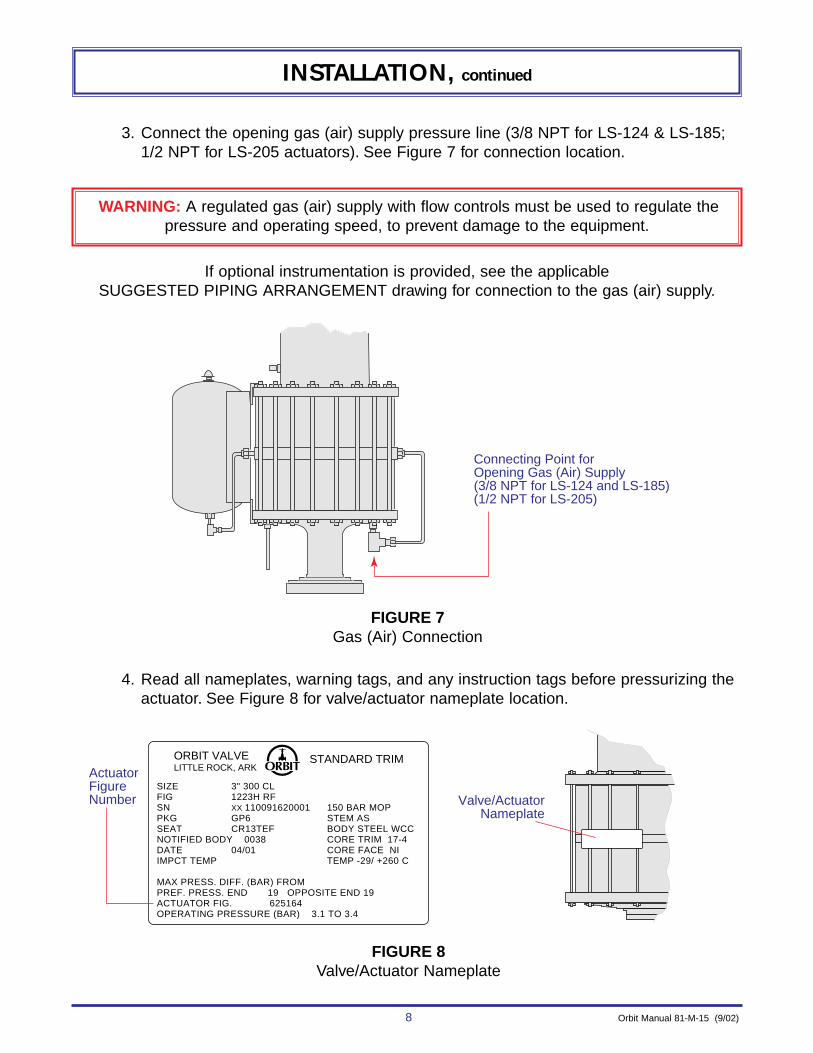
3. Connect the opening gas (air) supply pressure line (3/8 NPT for LS-124 & LS-185;1/2 NPT for LS-205 actuators). See Figure 7 for connection location.
WARNING: A regulated gas (air) supply with flow controls must be used to regulate thepressure and operating speed, to prevent damage to the equipment.
If optional instrumentation is provided, see the applicable SUGGESTED PIPING ARRANGEMENT drawing for connection to the gas (air) supply.
Connecting Point for Opening Gas (Air) Supply(3/8 NPT for LS-124 and LS-185)(1/2 NPT for LS-205)
4. Read all nameplates, warning tags, and any instruction tags before pressurizing theactuator. See Figure 8 for valve/actuator nameplate location.
Valve/ActuatorNameplate
Actuator Figure Number
ORBIT VALVELITTLE ROCK, ARK
STANDARD TRIM
SIZE 3" 300 CLFIG 1223H RFSN XX 110091620001 150 BAR MOPPKG GP6 STEM ASSEAT CR13TEF BODY STEEL WCCNOTIFIED BODY 0038 CORE TRIM 17-4DATE 04/01 CORE FACE NIIMPCT TEMP TEMP -29/ +260 C
MAX PRESS. DIFF. (BAR) FROMPREF. PRESS. END 19 OPPOSITE END 19ACTUATOR FIG. 625164OPERATING PRESSURE (BAR) 3.1 TO 3.4
FIGURE 8Valve/Actuator Nameplate
FIGURE 7Gas (Air) Connection
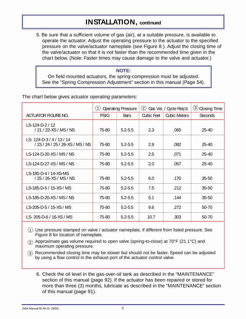
Operating Pressure Gas Vol. / Cycle Req’d. Closing TimeACTUATOR FIGURE NO. PSIG Bars Cubic Feet Cubic Meters Seconds
LS-124-D-2 / 12/ 21 / 22-XS / MS / NS 75-80 5.2-5.5 2.3 .065 25-40
LS- 124-D-3 / 4 / 13 / 14/ 23 / 24 / 25 / 26-XS / MS / NS 75-80 5.2-5.5 2.9 .082 25-40
LS-124-D-20-XS / MS / NS 75-80 5.2-5.5 2.5 .071 25-40
LS-124-D-27-XS / MS / NS 75-80 5.2-5.5 2.0 .057 25-40
LS-185-D-4 / 14-XS-MS/ 25 / 26-XS / MS / NS 75-80 5.2-5.5 6.0 .170 35-50
LS-185-D-5 / 15-XS / MS 75-80 5.2-5.5 7.5 .212 35-50
LS-185-D-20-XS / MS / NS 75-80 5.2-5.5 5.1 .144 35-50
LS-205-D-5 / 15-XS / MS 75-80 5.2-5.5 9.6 .272 50-70
LS- 205-D-6 / 16-XS / MS 75-80 5.2-5.5 10.7 .303 50-70
Use pressure stamped on valve / actuator nameplate, if different from listed pressure. See Figure 8 for location of nameplate.
Approximate gas volume required to open valve (spring-to-close) at 70°F (21.1°C) and maximum operating pressure.
Recommended closing time may be slower but should not be faster. Speed can be adjustedby using a flow control in the exhaust port of the actuator control valve.
3
2
1
321
The chart below gives actuator operating parameters:
Orbit Manual 81-M-15 (9/02) 9
INSTALLATION, continued
5. Be sure that a sufficient volume of gas (air), at a suitable pressure, is available tooperate the actuator. Adjust the operating pressure to the actuator to the specifiedpressure on the valve/actuator nameplate (see Figure 8 ). Adjust the closing time ofthe valve/actuator so that it is not faster than the recommended time given in thechart below. (Note: Faster times may cause damage to the valve and actuator.)
NOTE:On field mounted actuators, the spring-compression must be adjusted.
See the “Spring Compression Adjustment” section in this manual (Page 54).
6. Check the oil level in the gas-over-oil tank as described in the “MAINTENANCE”section of this manual (page 92). If the actuator has been repaired or stored formore than three (3) months, lubricate as described in the “MAINTENANCE” sectionof this manual (page 91).
10 Orbit Manual 81-M-15 (9/02)
INSTALLATION, continued
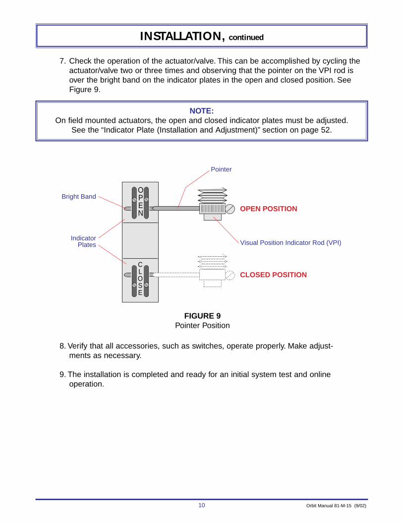
7. Check the operation of the actuator/valve. This can be accomplished by cycling theactuator/valve two or three times and observing that the pointer on the VPI rod isover the bright band on the indicator plates in the open and closed position. SeeFigure 9.
NOTE:On field mounted actuators, the open and closed indicator plates must be adjusted.
See the “Indicator Plate (Installation and Adjustment)” section on page 52.
OPEN
CLOSE
Pointer
OPEN POSITION
Bright Band
IndicatorPlates
CLOSED POSITION
Visual Position Indicator Rod (VPI)
8. Verify that all accessories, such as switches, operate properly. Make adjust-ments as necessary.
9. The installation is completed and ready for an initial system test and onlineoperation.
FIGURE 9Pointer Position

Orbit Manual 81-M-15 (9/02) 11
INSTALLATION, continued
CONVERSION OF HANDWHEEL OPERATED VALVES TO ACTUATOR OPERATED
VALVES and ACTUATOR MOUNTING PROCEDURES ON “L” VALVESThe proper procedure to follow for the conversion of handwheel valves and actuator
mounting on “L” valves is dependent upon knowing the size and pressure class of the valveand determining the valve model. The following information will determine the valve model:
1
1
WARNING: If in doubt as to the proper procedure to follow, depressurize the valve before any disassembly is started to prevent PERSONAL INJURY and/or equipment damage.
VALVE MODEL IDENTIFICATION:I. 2x2, 3x2 ANSI 1500-2500 CLASS
3x3, 4x3 ANSI 400-1500 CLASS4x4, 6x4 ANSI 150-1500 CLASS6x6, 8x6 ANSI 150-600 CLASS8x8, 10x8 ANSI 150-300 CLASS2-1/2 API 2000-3000 WOG3 & 4 API 1000-3000 WOG
The valve model for the above sizes is determined by the valve serial number lettered prefix(see Figure 10 for location of valve serial number).
1. “HA” & “HB” prefix (models “HA”& “HB”) use procedure 1B on ..............pg. 152. “JA” & “JB” prefix (models “JA” & “JB”) use procedure 2B on ................pg. 18 3. No prefix (PREVIOUS models) use procedure 3B on.............................pg. 22
SIZE 3" 900 CLFIG 1523H RFSN XX110091620001 2160 MOPPKG GP6 STEM ASSEAT CR13TEF BODY STEEL WCCMFG 6D-0073 CORE TRIM 17-4DATE 04/01 CORE FACE NI
TEMP -20/+500 F
ORBIT VALVELITTLE ROCK, ARK
STANDARD TRIM
SIZE 3" 300 CLFIG 1223H RFSN XX 110091620001 150 BAR MOPPKG GP6 STEM ASSEAT CR13TEF BODY STEEL WCC NOTIFIED BODY 0038 CORE TRIM 17-4DATE 04/01 CORE FACE NIIMPCT TEMP TEMP -29/+260 C
MAX PRESS. DIFF. (BAR) FROMPREF. PRESS. END 19 OPPOSITE END 19ACTUATOR FIG. 625164OPERATING PRESSURE (BAR) 3.1 TO 3.4
ORBIT VALVELITTLE ROCK, ARK
STANDARD TRIM
X X 1 2 3 4 5 6
Lettered Prefix
Stamped ValveSerial Number
2
Actuator/Valve or ActuatorSerial Number with Lettered Prefix 2
Valve Serial Number with Lettered Prefix
VALVE NAMEPLATE ACTUATOR / VALVE or ACTUATOR NAMEPLATE
2
NOTES:An “L” Valve is an Orbit term used to define a valve which is ready for actuator attachment.(The handwheel assembly has been removed and any adapter flanges, if required, are installedon the valve bonnet.) The “L” does not appear as a prefix or suffix to the valve serial number
Some valve models do not have a lettered prefix to the serial number.These are called “PREVIOUS” models.
2
1
FIGURE 10Valve Serial Number Location
12 Orbit Manual 81-M-15 (9/02)
INSTALLATION, continued
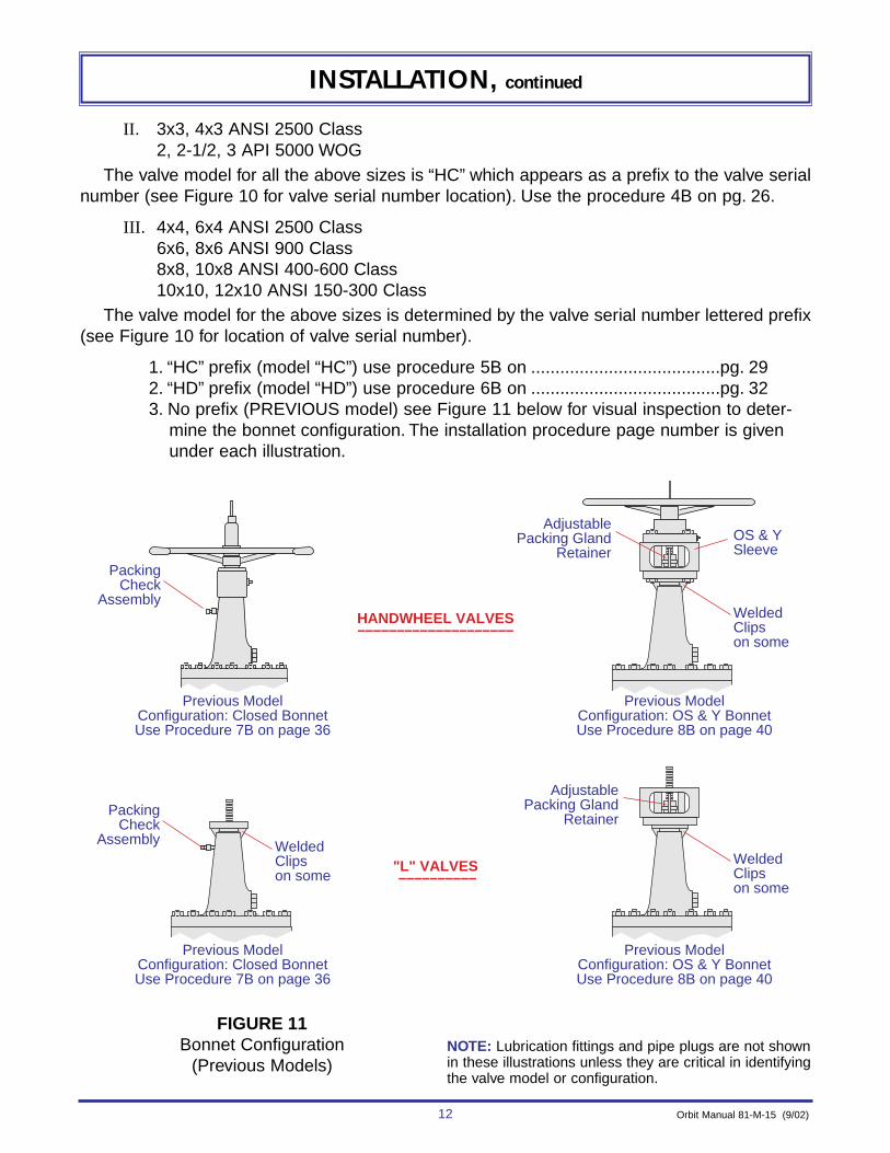
II. 3x3, 4x3 ANSI 2500 Class2, 2-1/2, 3 API 5000 WOG
The valve model for all the above sizes is “HC” which appears as a prefix to the valve serialnumber (see Figure 10 for valve serial number location). Use the procedure 4B on pg. 26.
III. 4x4, 6x4 ANSI 2500 Class6x6, 8x6 ANSI 900 Class8x8, 10x8 ANSI 400-600 Class10x10, 12x10 ANSI 150-300 Class
The valve model for the above sizes is determined by the valve serial number lettered prefix(see Figure 10 for location of valve serial number).
1. “HC” prefix (model “HC”) use procedure 5B on .......................................pg. 29 2. “HD” prefix (model “HD”) use procedure 6B on .......................................pg. 32 3. No prefix (PREVIOUS model) see Figure 11 below for visual inspection to deter-
mine the bonnet configuration. The installation procedure page number is givenunder each illustration.
NOTE: Lubrication fittings and pipe plugs are not shownin these illustrations unless they are critical in identifyingthe valve model or configuration.
OS & Y Sleeve
Welded Clipson some
HANDWHEEL VALVES––––––––––––––––––––
"L" VALVES ––––––––––
PackingCheck
Assembly
AdjustablePacking Gland
Retainer
Previous ModelConfiguration: Closed BonnetUse Procedure 7B on page 36
Previous ModelConfiguration: Closed BonnetUse Procedure 7B on page 36
Previous ModelConfiguration: OS & Y BonnetUse Procedure 8B on page 40
Previous ModelConfiguration: OS & Y BonnetUse Procedure 8B on page 40
PackingCheck
AssemblyWelded Clipson some
Welded Clipson some
AdjustablePacking Gland
Retainer
FIGURE 11Bonnet Configuration
(Previous Models)

Orbit Manual 81-M-15 (9/02) 13
INSTALLATION, continued
OS & Y Sleeve
HANDWHEEL VALVES––––––––––––––––––––
"L" VALVES ––––––––––
PackingCheckAssembly
AdjustablePacking Gland
Retainer
Previous ModelConfiguration: Closed BonnetUse Procedure 9B on page 44
Previous ModelConfiguration: Closed BonnetUse Procedure 9B on page 44
Previous ModelConfiguration: OS & Y Bonnet
Use Procedure 10B on page 48
Previous ModelConfiguration: OS & Y Bonnet
Use Procedure 10B on page 48
PackingCheckAssembly
OS & Y Sleeve
AdjustablePacking Gland
Retainer
IV. 6x6, 8x6 ANSI 1500-2500 Class8x8, 10x8 ANSI 900 Class10x10, 12x10 ANSI 400-900 Class12x12, 14x12, 16x12 ANSI 400-600 Class
The valve model for the above sizes is determined by the valve serial number lettered prefix(see figure 10 for valve serial number location).
1. “HC” prefix (model “HC”) use procedure 9B on......................................pg. 442. “HD” prefix (model “HD”) use procedure 10B on ...................................pg. 483. No prefix (PREVIOUS model) see Figure 12 below for visual inspection to deter-
mine the bonnet configuration. The installation procedure page number is givenunder each illustration.
FIGURE 12Bonnet Configuration
(Previous Models)
NOTE: Lubrication fittings and pipe plugs are not shownin these illustrations unless they are critical in identifyingthe valve model or configuration.

14 Orbit Manual 81-M-15 (9/02)
INSTALLATION, continued
OS & Y Sleeve
HANDWHEEL VALVES––––––––––––––––––––
"L" VALVES ––––––––––
PackingCheckAssembly
AdjustablePacking Gland
Retainer
Previous ModelConfiguration: Closed BonnetUse Procedure 5B on page 29
Previous ModelConfiguration: Closed BonnetUse Procedure 5B on page 29
Previous ModelConfiguration: OS & Y BonnetUse Procedure 6B on page 32
Previous ModelConfiguration: OS & Y BonnetUse Procedure 6B on page 32
PackingCheckAssembly
OS & Y Sleeve
AdjustablePacking Gland
Retainer
V. 12x12, 14x12, 16x12 ANSI 150-300 Class
The valve model for the above sizes is determined by the valve serial number lettered prefix(see Figure 10 for location of valve serial number).
1. “HC” prefix (model “HC”) use procedure 5B on.......................................pg. 292. “HD” prefix (model “HD”) use procedure 6B on.......................................pg. 323. No prefix (PREVIOUS model) see Figure 13 below for visual inspection to deter-
mine the bonnet configuration. The installation procedure page number is givenunder each illustration.
FIGURE 13Bonnet Configuration
(Previous Models)
NOTE: Lubrication fittings and pipe plugs are not shownin these illustrations unless they are critical in identifyingthe valve model or configuration.

Orbit Manual 81-M-15 (9/02) 15
INSTALLATION, continued
HANDWHEEL VALVE–––––––––––––––––––
"L" VALVE –––––––––
Ready for Actuator Attachment
Nut
Valve Stem
Bearingsand
Races
Handwheel Valve Stem
V.P.I. Rod
WasherDrive Nut
Drive NutRetainer
Nut & BoltBonnet
Hex HeadStem GuideDO NOT REMOVE
Stem Protector(Threaded)
Hex HeadStem GuideDO NOT REMOVE
ValveBonnetFlange
FIGURE 14Handwheel to “L” Valve (Procedure - 1B)
WARNING: This mounting and conversion procedure is for valve models “HA” and“HB”, size & pressures:
2x2, 3x2 ANSI 1500-2500 CLASS 8x8, 10x8 ANSI 150-300 CLASS3x3, 4x3 ANSI 400-1500 CLASS 2-1/2 API 2000-3000 WOG4x4, 6x4 ANSI 150-1500 CLASS 3 & 4 API 1000-3000 WOG6x6, 8x6 ANSI 150-600 CLASS
BEFORE converting or mounting, be certain this is the correct procedure. Failure todo this could result in PERSONAL INJURY and/or equipment damage. See pages11-14 for identifying other procedures.
Refer to Figure 14 for steps 1 through 6.(NOTE: Steps 1 through 6 are omitted if the handwheel assembly has been removed.)
1. Fully open the valve with the handwheel.2. Remove stem protector, washer, and V.P.I. rod with nut.3. Remove handwheel.4. Remove nuts & bolts holding the drive nut retainer.5. Remove drive nut retainer, drive nut (left hand threads), bearings and races.6. The valve is now an “L” valve, as shown and is ready for actuator attachment.
CONVERSION & MOUNTING PROCEDURE - 1B

16 Orbit Manual 81-M-15 (9/02)
INSTALLATION, continued
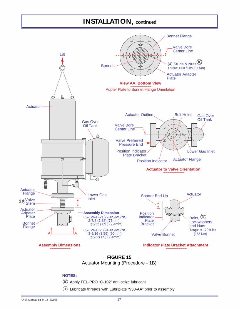
Refer to Figure 15 for steps 7 through 14. (Lubricate as noted in figure.)
7. Install and orientate the actuator plate to the valve bonnet flange using four (4) studs& nuts. Tighten to 60 ft-lbs (81 Nm) using a criss-cross pattern. See view A-A.
8. Thread the actuator unit onto the valve stem (left hand threads) until the distancebetween the actuator flange and the actuator adapter plate is equal to the assemblydimension for the appropriate actuator. (NOTE: When setting the assembly dimen-sion, the valve is in the full-open position and the actuator is in the full-closed posi-tion.)
9. Orientate the actuator to the valve by noting the relationship of the lower gas inletand the valve bore centerline.
10. Lower the actuator until the actuator flange and adapter plate contact. (NOTE: If theydo not contact due to actuator spring compression, apply gas pressure to the lowergas inlet, starting at 20 psig (1.4 bars) and increasing by 5 psig (0.35 bars) steps untilthey contact. (Do not exceed rated pressure stamped on nameplate of the actuator.)
11. Install the position indicator plate bracket, bolts, lock washers & nuts, and tighten to120 ft lbs (163 Nm) using a criss-cross pattern.
12. Install any accessories not already installed to the actuator unit or valve.
13. Lubricate the actuator and check/fill the gas-over-oil tank as described in the “MAINTENANCE” section on page 91 . Adjust the spring compression as detailed inthe “SPRING COMPRESSION ADJUSTMENT” section on page 54 . Install andadjust the visual position indicator plates as detailed in the “INDICATOR PLATES(INSTALLATION & ADJUSTMENT)” section on page 52.
14. The actuator mounting is complete.
CAUTION:Be sure hands and tools are not between the actuator flange and adapter
plate, as the actuator will move quickly to make contact with the adapter plate.
Orbit Manual 81-M-15 (9/02) 17
INSTALLATION, continued
Actuator
Bonnet Flange
Actuator AdapterPlate
Valve BoreCenter Line
(4) Studs & NutsTorque = 60 ft-lbs (81 Nm)
Bonnet
Actuator Outline Bolt Holes Gas OverOil Tank
Lower Gas Inlet
Actuator Flange
Bolts, Lockwashersand NutsTorque = 120 ft-lbs (163 Nm)
ActuatorShorter End UpLower Gas Inlet
ActuatorFlange
Gas OverOil Tank
ActuatorAdpater
Plate
Lift
ValveStem
BonnetFlange
A A
View AA, Bottom View ––––––––––
Adpter Plate to Bonnet Flange Orientation
Actuator to Valve Orientation ––––––––––
Indicator Plate Bracket Attachment ––––––––––
Assembly Dimensions ––––––––––
Valve BoreCenter Line
Valve PreferredPressure End
Position IndicatorPlate Bracket
PositionIndicator
PlateBracket
Position Indicator
Valve Bonnet
Assembly DimensionLS-124-D-21/22-XS/MS/NS 2-7/8 (2.88) (73mm) +3/32 (.09 ) (2.4mm) LS-124-D-23/24-XS/MS/NS 3-9/16 (3.56) (90mm) +3/32(.09) (2.4mm)
FIGURE 15Actuator Mounting (Procedure - 1B)
NOTES:
Apply FEL-PRO “C-102” anti-seize lubricant
Lubricate threads with Lubriplate “930-AA” prior to assembly

18 Orbit Manual 81-M-15 (9/02)
INSTALLATION, continued
HANDWHEEL VALVE–––––––––––––––––––
PRELIMINARY "L" VALVE –––––––––––––––––––––––
Valve Stem
Hex HeadStem GuideDO NOT REMOVE
Handwheel
Bonnet
Adapter Flange
Adapter Flange (REF)
2-3/4" - 12UNC Thread
Threads to beClean & Dry
PreliminaryAssembly
Dimension1/4" (.25) (6.4 mm)
+1/64" (.015) (0.4mm)
Valve Bore Center Line
Nut
Valve Stem
Bearingsand
Races
V.P.I. Rod
WasherDrive Nut
Threaded Drive NutRetainer
Set ScrewBonnet
Stem Protector(Threaded)
Hex HeadStem GuideDO NOT REMOVE
Flange BoltHoles to be on
Valve Bore Centerline View A-A
AA
FIGURE 16Handwheel to “L” Valve (Procedure - 2B)
WARNING: This mounting and conversion procedure is for valve models “JA” and “JB”, size & pressures:
2x2, 3x2 ANSI 1500-2500 CLASS 8x8, 10x8 ANSI 150-300 CLASS3x3, 4x3 ANSI 400-1500 CLASS 2-1/2 API 2000-3000 WOG4x4, 6x4 ANSI 150-1500 CLASS 3 & 4 API 1000-3000 WOG6x6, 8x6 ANSI 150-600 CLASS
BEFORE converting or mounting, be certain this is the correct procedure. Failure todo this could result in PERSONAL INJURY and/or equipment damage. See pages11-14 for identifying other procedures.
CONVERSION & MOUNTING PROCEDURE - 2B
Refer to Figure 16 for steps 1 through 8.(NOTE: Steps 1 through 8 are omitted if the handwheel assembly has been removed and theadapter assembly has previously been mounted.)
1. Fully open valve with handwheel.2. Remove stem protector, washer, and VPI rod with nut.3. Remove handwheel.4. Loosen set screw and remove drive nut retainer.5. Remove drive nut (left hand threads), bearings and races.6. Clean threads on bonnet. Do not lubricate.7. Screw adapter flange (2-3/4-12 UNC thread) onto bonnet until the preliminary assembly
dimension is achieved with two bolt holes in the adapter flange aligned with the valvebore centerline. (NOTE: Do not install set screws in the adapter flange until step 12.)
8. Valve is now a preliminary “L” valve, as shown, and is ready for the actuator adapterplate attachment.

Actuator AdapterPlate
1/4 x 3/4 x 3/4 Welding BridgeLocate between bolts
Valve BoreCenter Line
View A-A, Bottom View ––––––––––
2
2
1
Valve Stem
(4) Studs &Nuts, Torque
60 ft-lbs (81 Nm) Bonnet
Bonnet
Adapter Flange
Adapter Flange
1/4 - 20 Set Screw(2) required
ActuatorAdapter Plate
Assembly Clearance1/32" (.03) (0.8mm)
+1/64" (.015) (0.4mm)
AA
FIGURE 17Actuator Adapter Plate Installation
(Procedure - 2B)
Orbit Manual 81-M-15 (9/02) 19
INSTALLATION, continued
Refer to Figure 17 for steps 9 through 13. (NOTE: Steps 10,12 and 13 are omitted if the bon-net adapter flange has previously been welded to the valve bonnet.)
9. Install and orientate the actuator adapter plate to the bonnet adapter flange asshown in view A-A.
10. Check the assembly clearance, 1/32 (.03) (0.8 mm), between the actuator adapterplate and the bonnet adapter flange. Adjust if necessary, by rotating the bonnetadapter flange in 90° increments. Be sure orientation of the plate and adapter is stillcorrect.
11. Install the four (4) studs & nuts. Tighten to 60 ft-lbs (81 Nm) using a criss-cross pattern.
12. Place a cup-point punch in each set screw hole on the bonnet adapter flange, strikesharply with a hammer, install the two (2) set screws, and tighten securely. (NOTE:Factory mounted adapter flanges do not have set screws.)
13. Weld the bonnet adapter flange to the valve bonnet with 1/4 x 3/4 x 3/4 inch (6 x 20 x 20 mm) welding bridge as shown. (Recommended, but not required.)
NOTE: Installation of an adapter flange is intended to be permanent.If conversion back to handwheel operation is later desired,
“bolt on” type drive nut retainers can be obtained from Orbit.
NOTES:
Included with field mounted adapter flanges only.
Set assembly clearance before installing the four (4) studs & nuts, tightening the two (2) set screws, orwelding bridge to bonnet and flange.
Apply FEL-PRO “C-102” anti-seize lubricant
2
1

20 Orbit Manual 81-M-15 (9/02)
INSTALLATION, continued
Refer to Figure 18 for steps 14 through 20. (Lubricate as noted in figure.)
14. Thread the actuator unit onto the valve stem (left hand threads) until the distancebetween the actuator flange and the actuator adapter plate is equal to the assemblydimension for the appropriate actuator.(NOTE: When setting the assembly dimension, the valve is in the full-open positionand the actuator is in the full-closed position.)
15. Orientate the actuator to the valve by noting the relationship of the lower gas inletand the valve bore centerline.
16. Lower the actuator until the actuator flange and adapter plate contact.(NOTE: If they do not contact due to actuator spring compression, apply gas pres-sure to the lower gas inlet starting at 20 psig (1.4 bars) and increasing by 5 psig(0.35 bars) steps until they contact.) (Do not exceed rated pressure stamped onnameplate for actuator.)
17. Install the position indicator plate bracket, bolts, lockwashers & nuts, andtighten to 120 ft-lbs (163 Nm) using a criss-cross pattern.
18. Install any accessories not already installed to the actuator unit or valve.
19. Lubricate the actuator and check/fill the gas-over-oil tank as described in the“MAINTENANCE” section on page 91. Adjust the spring compression as detailedin the “SPRING COMPRESSION ADJUSTMENT” section on page 54. Install andadjust the visual position indicator plates as detailed in the “INDICATOR PLATES(INSTALLATION & ADJUSTMENT)” section on page 52.
20. The actuator mounting is complete.
CAUTION:Be sure hands and tools are not between the actuator flange and
the adapter plate, as the actuator will move quickly to makecontact with the adapter plate.

Orbit Manual 81-M-15 (9/02) 21
INSTALLATION, continued
Actuator
Actuator Outline Bolt Holes Gas OverOil Tank
Lower Gas Inlet
Actuator Flange
Bolts, Lockwashersand NutsTorque = 120 ft-lbs (163 Nm)
ActuatorShorter End Up
Lower Gas Inlet
ActuatorFlange
Gas OverOil Tank
ActuatorAdpater
Plate
Lift
Valve Stem
BonnetFlange
Actuator to Valve Orientation ––––––––––
Indicator Plate Bracket Attachment ––––––––––
Assembly Dimensions ––––––––––
Valve BoreCenter Line
Valve PreferredPressure End
Position IndicatorPlate Bracket
PositionIndicator
PlateBracket
Position Indicator
Valve Bonnet
Assembly DimensionLS-124-D-21/22-XS/MS/NS 2-7/8 (2.88) (73mm) +3/32 (.09) (2.4mm) LS-124-D-23/24-XS/MS/NS 3-9/16 (3.56) (90mm) +3/32(.09) (2.4mm)
FIGURE 18Actuator Mounting (Procedure - 2B)
NOTES:
Apply FEL-PRO “C-102” anti-seize lubricant
Lubricate threads with Lubriplate “930-AA” prior to assembly
22 Orbit Manual 81-M-15 (9/02)
INSTALLATION, continued
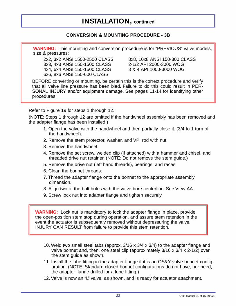
WARNING: This mounting and conversion procedure is for “PREVIOUS” valve models, size & pressures:
2x2, 3x2 ANSI 1500-2500 CLASS 8x8, 10x8 ANSI 150-300 CLASS3x3, 4x3 ANSI 150-1500 CLASS 2-1/2 API 2000-3000 WOG4x4, 6x4 ANSI 150-1500 CLASS 3 & 4 API 1000-3000 WOG6x6, 8x6 ANSI 150-600 CLASS
BEFORE converting or mounting, be certain this is the correct procedure and verifythat all valve line pressure has been bled. Failure to do this could result in PER-SONAL INJURY and/or equipment damage. See pages 11-14 for identifying otherprocedures.
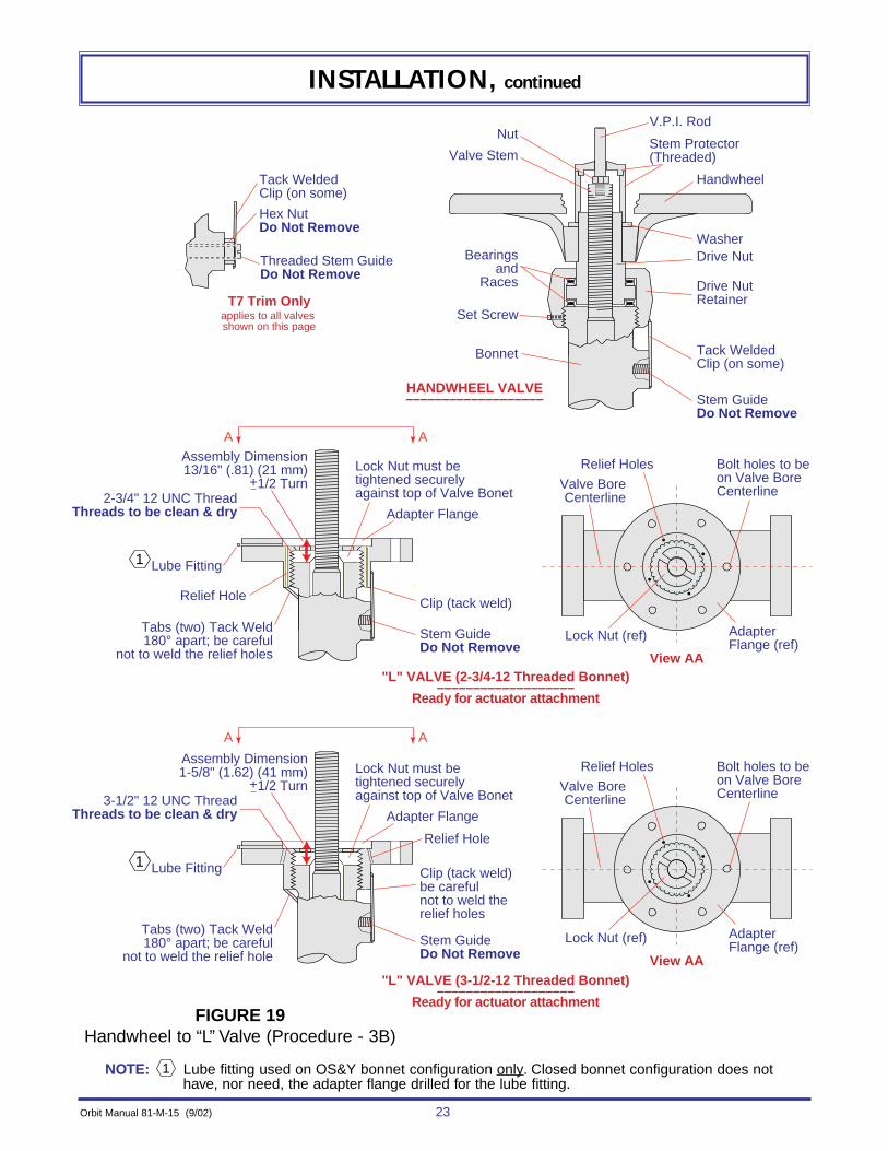
CONVERSION & MOUNTING PROCEDURE - 3B
Refer to Figure 19 for steps 1 through 12.(NOTE: Steps 1 through 12 are omitted if the handwheel assembly has been removed andthe adapter flange has been installed.)
1. Open the valve with the handwheel and then partially close it. (3/4 to 1 turn ofthe handwheel).
2. Remove the stem protector, washer, and VPI rod with nut.3. Remove the handwheel.4. Remove the set screw, welded clip (if attached) with a hammer and chisel, and
threaded drive nut retainer. (NOTE: Do not remove the stem guide.)5. Remove the drive nut (left hand threads), bearings, and races.6. Clean the bonnet threads.7. Thread the adapter flange onto the bonnet to the appropriate assembly
dimension.8. Align two of the bolt holes with the valve bore centerline. See View AA.9. Screw lock nut into adapter flange and tighten securely.
10. Weld two small steel tabs (approx. 3/16 x 3/4 x 3/4) to the adapter flange andvalve bonnet and, then, one steel clip (approximately 3/16 x 3/4 x 2-1/2) overthe stem guide as shown.
11. Install the lube fitting in the adapter flange if it is an OS&Y valve bonnet config-uration. (NOTE: Standard closed bonnet configurations do not have, nor need,the adapter flange drilled for a lube fitting.)
12. Valve is now an “L” valve, as shown, and is ready for actuator attachment.
WARNING: Lock nut is mandatory to lock the adapter flange in place, providethe open-position stem stop during operation, and assure stem retention in theevent the actuator is subsequently removed without depressuring the valve.INJURY CAN RESULT from failure to provide this stem retention.
Orbit Manual 81-M-15 (9/02) 23
INSTALLATION, continued
T7 Trim Onlyapplies to all valves shown on this page
2-3/4" 12 UNC ThreadThreads to be clean & dry
Assembly Dimension13/16" (.81) (21 mm)
+1/2 Turn
"L" VALVE (2-3/4-12 Threaded Bonnet)–––––––––––––––––––
Ready for actuator attachment
View AA
Tack WeldedClip (on some)
Hex NutDo Not Remove
Threaded Stem GuideDo Not Remove
Lock Nut must betightened securely against top of Valve Bonet
HANDWHEEL VALVE–––––––––––––––––––
Handwheel
Nut
Valve Stem
Bearingsand
Races
V.P.I. Rod
WasherDrive Nut
Tack WeldedClip (on some)
Stem GuideDo Not Remove
Drive NutRetainer
Set Screw
Bonnet
Stem Protector(Threaded)
A A
A A
1
Clip (tack weld)
Bolt holes to beon Valve Bore CenterlineValve Bore
Centerline
Lock Nut (ref) Adapter Flange (ref)
Relief Holes
Adapter Flange
Tabs (two) Tack Weld180° apart; be careful
not to weld the relief holes
Relief Hole
Lube Fitting
Stem GuideDo Not Remove
3-1/2" 12 UNC ThreadThreads to be clean & dry
Assembly Dimension1-5/8" (1.62) (41 mm)
+1/2 Turn
"L" VALVE (3-1/2-12 Threaded Bonnet)–––––––––––––––––––
Ready for actuator attachment
View AA
Lock Nut must betightened securely against top of Valve Bonet
1Clip (tack weld)be carefulnot to weld therelief holes
Bolt holes to beon Valve Bore CenterlineValve Bore
Centerline
Lock Nut (ref) Adapter Flange (ref)
Relief Holes
Adapter Flange
Tabs (two) Tack Weld180° apart; be careful
not to weld the relief hole
Lube Fitting
Stem GuideDo Not Remove
Relief Hole
FIGURE 19Handwheel to “L” Valve (Procedure - 3B)
NOTE: Lube fitting used on OS&Y bonnet configuration only. Closed bonnet configuration does nothave, nor need, the adapter flange drilled for the lube fitting.
1

24 Orbit Manual 81-M-15 (9/02)
INSTALLATION, continued
Refer to Figure 20 for steps 13 through 19. (Lubricate as noted in figure.)
13. Thread the actuator unit onto the valve stem (left hand threads) until the distancebetween the actuator flange and the adapter flange is equal to the assemblydimension for the appropriate actuator. (NOTE: When setting the assembly dimen-sion, the valve is in the full-open position and the actuator is in the full-closed posi-tion.) (NOTE: Actuator models LS-124-D-21 & D-22 include an actuator adapterplate which is not used on this application. Other applications use this platebetween the actuator flange and the valve adapter flange.)
14. Orientate the actuator to the valve by noting the position of the lower gas inlet andthe valve bore centerline.
15. Lower the actuator until the actuator flange and adapter flange contact.(NOTE: If they do not contact due to actuator spring compression, apply gas pres-sure to the lower gas inlet, starting at 20 psig (1.4 bars) and increasing by 5 psig(0.35 bars) steps until they contact.) (Do not exceed rated pressure stamped onactuator nameplate.)
16. Install position indicator plate bracket, bolts, lock washers & nuts, and tighten to120 ft-lbs (163 Nm) using a criss-cross pattern.
17. Install any accessories not already installed to the actuator unit or valve.
18. Lubricate the actuator and check/fill the gas-over-oil tank as described in the“MAINTENANCE” section on page 91. Adjust the spring compression as detailed inthe “SPRING COMPRESSION ADJUSTMENT” section on page 54. Install andadjust the visual position indicator plates as detailed in the “INDICATOR PLATES(INSTALLATION & ADJUSTMENT)” section on page 52.
19. The actuator mounting is complete.
CAUTION:Be sure hands and tools are not between the actuator flange and
valve adapter flange, as the actuator will move quickly to makecontact with the valve adapter flange.

Orbit Manual 81-M-15 (9/02) 25
INSTALLATION, continued
Actuator Outline Bolt Holes Gas OverOil Tank
Lower Gas Inlet
Actuator Flange
Bolts, Lockwashersand NutsTorque = 120 ft-lbs (163 Nm)
ActuatorShorter End Up
Lower Gas Inlet
ActuatorFlange
ActuatorAdpater
Plate
Lift
Valve Stem
BonnetFlange
Actuator to Valve Orientation ––––––––––
Indicator Plate Bracket Attachment ––––––––––
Assembly Dimensions ––––––––––
Valve BoreCenter Line
Valve PreferredPressure End
Position IndicatorPlate Bracket
PositionIndicator
PlateBracket
Position Indicator
Valve Bonnet
Assembly DimensionLS-124-D-2/12/22-XS/MS/NS 2-7/8 (2.88) (73mm) +3/32 (.09 ) (2.4mm) LS-124-D-3/13-XS/MS/NS 3-9/16 (3.56) (90mm) +3/32(.09) (2.4mm)
Actuator
Gas OverOil Tank
FIGURE 20Actuator Mounting (Procedure - 3B)
NOTES:
Apply FEL-PRO “C-102” anti-seize lubricant
Lubricate threads with Lubriplate “930-AA” prior to assembly

26 Orbit Manual 81-M-15 (9/02)
INSTALLATION, continued
WARNING: This mounting and conversion procedure is for valve model “HC” size andpressure:
3 x 3, 4 x 3 ANSI 2500 CLASS2, 2-1/2, 3 ANSI 5000 W.O.G.
BEFORE converting or mounting, be certain this is the correct procedure. Failure todo this could result in PERSONAL INJURY and/or equipment damage. See pages11-13 for identifying other procedures.
CONVERSION & MOUNTING PROCEDURE - 4B
Refer to Figure 21 for steps 1 through 6.
(NOTE: Steps 1 through 6 are omitted if the handwheel assembly has been removed.)
1. Fully open the valve with the handhweel.2. Remove stem protector, washer, and V.P.I. rod with nut.3. Remove handwheel.4. Remove nuts & bolts holding the drive nut retainer.5. Remove drive nut retainer, drive nut (left hand threads), bearings and races.6. Valve is now an “L” valve, as shown, and is ready for actuator attachment.
HANDWHEEL VALVE–––––––––––––––––––
"L" VALVE –––––––––
Ready for Actuator Attachment
Nut
Valve Stem
Bearingsand
Races
Handwheel Valve Stem
V.P.I. Rod
Washer
Drive Nut
Nut & Bolt
Bonnet
Bonnet
Stem Protector(Threaded)
Wiper Ring
Drive NutRetainer
Packing Retainer NutDO NOT REMOVE
Packing RingsDO NOT REMOVE
Packing Check
AssemblyDO NOT
REMOVE
PackingCheck
AssemblyDO NOT
REMOVE
PackingRetainer NutDO NOT REMOVE
FIGURE 21Handwheel to “L” Valve (Procedure - 4B)

Orbit Manual 81-M-15 (9/02) 27
INSTALLATION, continued
Refer to Figure 22 for steps 7 through 14. (Lubricate as noted in figure.)7. Install and orientate the actuator adapter plate to the valve bonnet flange using
four (4) studs & nuts. Tighten to 60 ft-lbs (81 Nm) using a criss-cross pattern. Seeview A-A.
8. Thread the actuator unit onto the valve stem (left hand threads) until the distancebetween the actuator flange and the actuator adapter plate is equal to the assem-bly dimension for the appropriate actuator.(NOTE: When setting the assembly dimension, the valve is in the full open posi-tion and the actuator is in the full-closed position.)
9. Orientate the actuator to the valve by noting the relationship of the lower gas inletto the valve bore centerline.
10. Lower the actuator until the actuator flange and adapter plate contact.(NOTE: If they do not contact due to actuator spring compression, apply gaspressure to the lower gas inlet starting at 20 psig (1.4 bars) and increasing bysteps of 5 psig (0.35 bars) until they contact.) (Do not exceed rated pressurestamped on nameplate for actuator.)
on nameplate for actuator.)
11. Install the position indicator plate bracket, bolts, lockwashers & nuts, and tightento 120 ft-lbs (163 Nm) using a criss-cross pattern.
12. Install any accessories, not already installed, to the actuator unit or valve.
13. Lubricate the actuator and check/fill the gas-over-oil tank as described in the“MAINTENANCE” section on page 91. Adjust the spring compression as detailedin the “SPRING COMPRESSION ADJUSTMENT” section on page 54. Install andadjust the visual position indicator plates as detailed in the “INDICATOR PLATES(INSTALLATION & ADJUSTMENT)” section on page 52 .
14. The actuator mounting is complete.
CAUTION:Be sure hands and tools are not between the actuator flange and
the adapter plate, as the actuator will move quickly to makecontact with the adapter plate.

28 Orbit Manual 81-M-15 (9/02)
INSTALLATION, continued
Assembly DimensionLS-124-D-20-XS/MSLS-185-D-20-XS/MS 3 (3.00) (76mm) +3/32 (.09 ) (2.4mm) LS-124-D-27-XS/MS 2-1/2 (2.50) (64mm) +3/32(.09) (2.4mm)
Actuator
Bonnet Flange
Actuator AdapterPlate
Valve BoreCenter Line
(4) Studs & NutsTorque = 60 ft-lbs (81 Nm)
Bonnet
Actuator Outline Bolt Holes Gas OverOil Tank
Lower Gas Inlet
Actuator Flange
Bolts, Lockwashersand NutsTorque = 120 ft-lbs (163 Nm)
ActuatorShorter End UpLower Gas Inlet
ActuatorFlange
Gas OverOil Tank
ActuatorAdapter
Plate
Lift
ValveStem
BonnetFlange
A A
View AA, Bottom View ––––––––––
Adpter Plate to Bonnet Flange Orientation
Actuator to Valve Orientation ––––––––––
Indicator Plate Bracket Attachment ––––––––––
Assembly Dimensions ––––––––––
Valve BoreCenter Line
Valve PreferredPressure End
Position IndicatorPlate Bracket
PositionIndicator
PlateBracket
Position Indicator
Valve Bonnet
FIGURE 22Actuator Mounting (Procedure - 4B)
NOTES:
Apply FEL-PRO “C-102” anti-seize lubricant
Lubricate threads with Lubriplate “930-AA” prior to assembly
Orbit Manual 81-M-15 (9/02) 29
INSTALLATION, continued
HANDWHEEL VALVE–––––––––––––––––––
"L" VALVE –––––––––
Ready for Actuator Attachment
Bearings & Races
Wiper Ring
Watertight Connector
Threaded Stem Protector
Handwheel Key
Handwheel
Bonnet
Bolts, Washers & Nuts
Internal Wrenching NutDO NOT REMOVE
Valve StemValve BonnetFlange
Packing Check
AssemblyDO NOT
REMOVE
VPI Rod
Hex Jam Nut
Valve Stem
Drive Nut
Drive NutRetainer
PackingCheck Assembly
DO NOT REMOVE
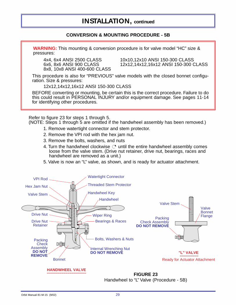
FIGURE 23Handwheel to “L” Valve (Procedure - 5B)
CONVERSION & MOUNTING PROCEDURE - 5B
Refer to figure 23 for steps 1 through 5.(NOTE: Steps 1 through 5 are omitted if the handwheel assembly has been removed.)
1. Remove watertight connector and stem protector.2. Remove the VPI rod with the hex jam nut.3. Remove the bolts, washers, and nuts4. Turn the handwheel clockwise until the entire handwheel assembly comes
loose from the valve stem. (Drive nut retainer, drive nut, bearings, races andhandwheel are removed as a unit.)
5. Valve is now an “L” valve, as shown, and is ready for actuator attachment.
WARNING: This mounting & conversion procedure is for valve model “HC” size &pressures:
4x4, 6x4 ANSI 2500 CLASS 10x10,12x10 ANSI 150-300 CLASS 6x6, 8x6 ANSI 900 CLASS 12x12,14x12,16x12 ANSI 150-300 CLASS 8x8, 10x8 ANSI 400-600 CLASS
This procedure is also for “PREVIOUS” valve models with the closed bonnet configu-ration. Size & pressures:
12x12,14x12,16x12 ANSI 150-300 CLASSBEFORE converting or mounting, be certain this is the correct procedure. Failure to dothis could result in PERSONAL INJURY and/or equipment damage. See pages 11-14for identifying other procedures.
30 Orbit Manual 81-M-15 (9/02)
INSTALLATION, continued
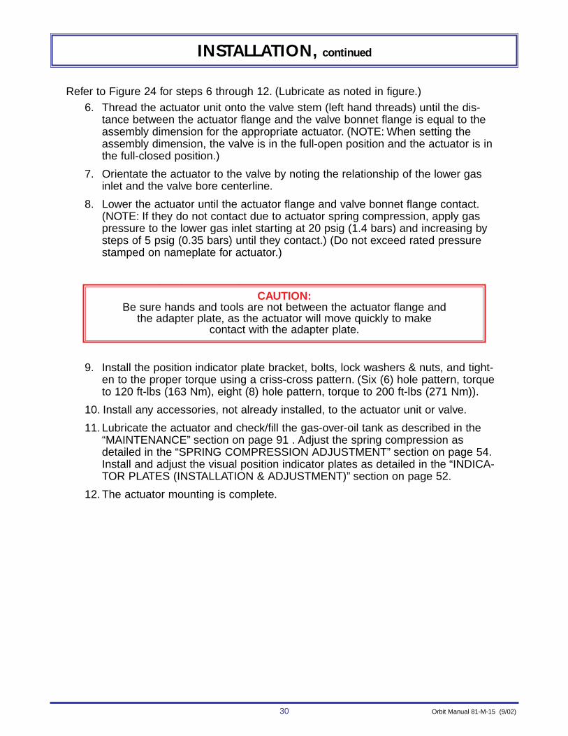
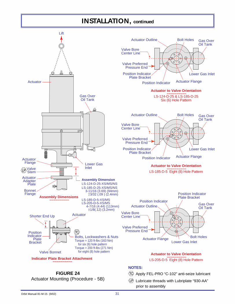
Refer to Figure 24 for steps 6 through 12. (Lubricate as noted in figure.)6. Thread the actuator unit onto the valve stem (left hand threads) until the dis-
tance between the actuator flange and the valve bonnet flange is equal to theassembly dimension for the appropriate actuator. (NOTE: When setting theassembly dimension, the valve is in the full-open position and the actuator is inthe full-closed position.)
7. Orientate the actuator to the valve by noting the relationship of the lower gasinlet and the valve bore centerline.
8. Lower the actuator until the actuator flange and valve bonnet flange contact.(NOTE: If they do not contact due to actuator spring compression, apply gaspressure to the lower gas inlet starting at 20 psig (1.4 bars) and increasing bysteps of 5 psig (0.35 bars) until they contact.) (Do not exceed rated pressurestamped on nameplate for actuator.)
on nameplate for actuator.)
9. Install the position indicator plate bracket, bolts, lock washers & nuts, and tight-en to the proper torque using a criss-cross pattern. (Six (6) hole pattern, torqueto 120 ft-lbs (163 Nm), eight (8) hole pattern, torque to 200 ft-lbs (271 Nm)).
10. Install any accessories, not already installed, to the actuator unit or valve.
11. Lubricate the actuator and check/fill the gas-over-oil tank as described in the“MAINTENANCE” section on page 91 . Adjust the spring compression asdetailed in the “SPRING COMPRESSION ADJUSTMENT” section on page 54.Install and adjust the visual position indicator plates as detailed in the “INDICA-TOR PLATES (INSTALLATION & ADJUSTMENT)” section on page 52.
12. The actuator mounting is complete.
CAUTION:Be sure hands and tools are not between the actuator flange and
the adapter plate, as the actuator will move quickly to makecontact with the adapter plate.
Orbit Manual 81-M-15 (9/02) 31
INSTALLATION, continued
Assembly DimensionLS-124-D-25-XS/MS/NSLS-185-D-25-XS/MS/NS 3-11/16 (3.69) (94mm) +3/32 (.09 ) (2.4mm) LS-185-D-5-XS/MSLS-205-D-5-XS/MS 4-7/16 (4.44) (113mm) +1/8(.12) (3.2mm)
Actuator
Actuator Outline Bolt Holes Gas OverOil Tank
Lower Gas Inlet
Actuator Flange
Bolts, Lockwashers & NutsTorque = 120 ft-lbs (163 Nm) for six (6) hole patternTorque = 200 ft-lbs (271 Nm) for eight (8) hole pattern
ActuatorShorter End Up
Lower Gas Inlet
ActuatorFlange
Gas OverOil Tank
ActuatorAdapter
Plate
Lift
ValveStem
BonnetFlange
Actuator to Valve Orientation ––––––––––
LS-124-D-25 & LS-185-D-25Six (6) Hole Pattern
Indicator Plate Bracket Attachment ––––––––––
Assembly Dimensions ––––––––––
Valve BoreCenter Line
Valve PreferredPressure End
Position IndicatorPlate Bracket
PositionIndicator
PlateBracket
Position Indicator
Valve Bonnet
Actuator Outline Bolt Holes Gas OverOil Tank
Lower Gas Inlet
Actuator Flange
Actuator to Valve Orientation ––––––––––
LS-185-D-5 Eight (8) Hole Pattern
Valve BoreCenter Line
Valve PreferredPressure End
Position IndicatorPlate Bracket
Position Indicator
Actuator Outline
Bolt Holes
Gas OverOil Tank
Lower Gas InletActuator Flange
Actuator to Valve Orientation ––––––––––
LS-205-D-5 Eight (8) Hole Pattern
Valve BoreCenter Line
Valve PreferredPressure End
Position IndicatorPlate Bracket
Position Indicator
FIGURE 24Actuator Mounting (Procedure - 5B)
NOTES:
Apply FEL-PRO “C-102” anti-seize lubricant
Lubricate threads with Lubriplate “930-AA”prior to assembly

32 Orbit Manual 81-M-15 (9/02)
INSTALLATION, continued
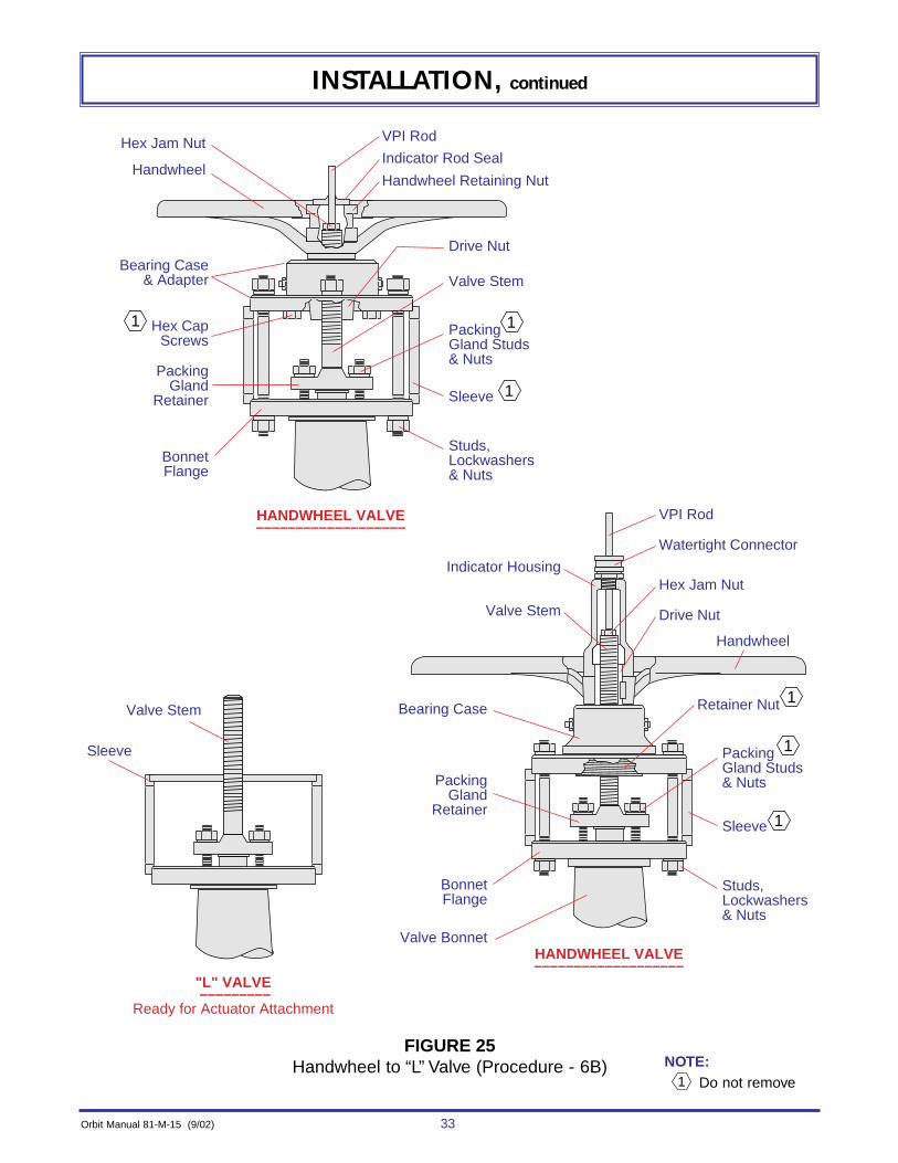
CONVERSION & MOUNTING PROCEDURE - 6B
Refer to Figure 25 for steps 1 through 5.(NOTE: Steps 1 through 5 are omitted if the handwheel assembly has been removed.)
1. Fully open valve with handwheel.
2. Remove the studs, lock-washers & nuts that hold the bearing case assembly to thesleeve.
3. Remove the entire handwheel and bearing case assembly as one unit by unscrew-ing it from the valve stem. (Left hand valve stem threads.) (NOTE: When it comesloose from the valve stem, lift it straight off the VPI rod.)
4. Remove the VPI rod with the hex jam nut.
5. The valve is now an “L” valve, as shown, and is ready for actuator attachment.
WARNING: This mounting & conversion procedure is for valve model “HD” size &pressures:
6x6, 8x6 ANSI 900 Class 10x10, 12x10, ANSI 150-300 Class 8x8, 10x8 ANSI 400-600 Class 12x12, 14x12, 16x12 ANSI 150-300 Class
This procedure is also for “PREVIOUS” valve models with the OS & Y bonnet configu-ration. Size & pressures:
12x12,14x12,16x12 ANSI 150-300 CLASSBEFORE converting or mounting, be certain this is the correct procedure. Failure to dothis could result in PERSONAL INJURY and/or equipment damage. See pages 11-14for identifying other procedures.
Orbit Manual 81-M-15 (9/02) 33
INSTALLATION, continued
HANDWHEEL VALVE–––––––––––––––––––
HANDWHEEL VALVE–––––––––––––––––––
"L" VALVE –––––––––
Ready for Actuator Attachment
Watertight Connector
Handwheel
Handwheel
Hex Jam Nut
Valve Bonnet
Sleeve
Studs, Lockwashers& Nuts
Valve Stem
Sleeve
Studs, Lockwashers& Nuts
VPI Rod
Hex Jam NutIndicator Housing
Valve Stem Drive Nut
Retainer Nut
Packing Gland Studs& NutsPacking
GlandRetainer
Bearing Case
BonnetFlange
BonnetFlange
PackingGland
Retainer
Hex CapScrews
Bearing Case& Adapter
Drive Nut
Valve Stem
1
1
Sleeve 1
1
1
Packing Gland Studs& Nuts
1
VPI Rod
Indicator Rod Seal
Handwheel Retaining Nut
FIGURE 25Handwheel to “L” Valve (Procedure - 6B) NOTE:
Do not remove1
34 Orbit Manual 81-M-15 (9/02)
INSTALLATION, continued
Refer to Figure 26 for steps 6 through 14. (Lubricate as noted in figure.)6. Orientate the valve sleeve as shown in the figure.
(NOTE: Notice the different orientations for the different actuator models.)
7. Thread the actuator unit onto the valve stem (left hand threads) until the dis-tance between the actuator flange and the valve sleeve is equal to the assem-bly dimension for the appropriate actuator.(NOTE: When setting the assembly dimension, the valve is in the full-open posi-tion and the actuator is in the full-closed position.)
8. Orientate the actuator to the valve by noting the relationship of the lower gasinlet to the valve bore centerline.(NOTE: Notice the different orientations for the different actuator models.)
9. Lower the actuator until the actuator flange and valve sleeve contact.(NOTE: If they do not contact due to actuator spring compression, apply gaspressure to the lower gas inlet starting at 20 psig (1.4 bars) and increasing bysteps of 5 psig (0.35 bars) until they contact.) (Do not exceed rated pressurestamped on the nameplate for the actuator.)
10. Check that the packing gland nuts on the valve (see Figure 25) are accessiblewith a wrench. If they are not accessible, the valve sleeve will need to be rotat-ed until they are.
11. Install the position indicator plate bracket, studs, lock washers & nuts, and tighten to the appropriate torque, using a criss-cross pattern.
12. Install any accessories, not already installed, to the actuator unit or valve. Besure the valve packing gland nuts are still accessible.
13. Lubricate the actuator and check/fill the gas-over-oil tank as described in the“MAINTENANCE” section on page 91. Adjust the spring compression asdetailed in the “SPRING COMPRESSION ADJUSTMENT” section on page 54.Install and adjust the visual position indicator plates as detailed in the “INDICA-TOR PLATES (INSTALLATION & ADJUSTMENT)” section on page 52.
14. The actuator mounting is complete.
CAUTION:Be sure hands and tools are not between the actuator flange and
the valve sleeve, as the actuator will move quickly to makecontact with the valve sleeve.

Orbit Manual 81-M-15 (9/02) 35
INSTALLATION, continued
FIGURE 26Actuator Mounting (Procedure - 6B)
NOTES:
Apply FEL-PRO “C-102” anti-seize lubricant
Lubricate threads with Lubriplate “930-AA”prior to assembly
C L
Assembly DimensionLS-185-D-15-XS/MS/NSLS-205-D-15-XS/MS 4-3/16 (4.19) (106mm) +1/8 (.12 ) (3.2mm)LS-185-D-26-XS/MS/NS 3-7/16 (3.44) (87mm) +3/32(.09) (24mm)
Actuator
Actuator Outline Bolt Holes Gas OverOil Tank
Lower Gas Inlet
Actuator Flange
Studs, Lockwashers & NutsTorque = 120 ft-lbs (163 Nm) for LS-185-D-26 ActuatorsTorque = 200 ft-lbs (271 Nm) for LS-185-D-15 Actuators LS-205-D-15 Actuators
Actuator
Sleeve
ShorterEnd UpLower Gas
Inlet
ActuatorFlange
Gas OverOil Tank
Sleeve
ValveStem
BonnetFlange
Actuator to Valve Orientation ––––––––––
LS-185-D-25 Six (6) Hole Pattern
Sleeve to Valve Orientation ––––––––––
LS-185-D-26 Actuator Six (6) Hole Pattern
Indicator Plate Bracket Attachment ––––––––––Assembly Dimensions
––––––––––
Valve BoreCenter Line
Valve PreferredPressure End
Position IndicatorPlate Bracket
PositionIndicator
PlateBracket
Position Indicator
Valve Bonnet
Valve BoreCenter Line
Sleeve
5" Window
FlangeHoles
Align edge of windowwith flange hole
Packing GlandRetainer
PreferredPressure End
Actuator Outline Bolt Holes Gas OverOil Tank
Lower Gas Inlet
Actuator Flange
Actuator to Valve Orientation ––––––––––
LS-185-D-15 Eight (8) Hole Pattern
Valve BoreCenter Line
Valve PreferredPressure End
Position IndicatorPlate Bracket
Position Indicator
Actuator Outline
Bolt Holes
Gas OverOil Tank
Lower Gas InletActuator Flange
Actuator to Valve Orientation ––––––––––
LS-205-D-15 Eight (8) Hole Pattern
Valve BoreCenter Line
Valve PreferredPressure End
Position IndicatorPlate Bracket
Position Indicator
Sleeve to Valve Orientation ––––––––––
LS-185-D-15 Actuator Eight (8) Hole Pattern
Valve BoreCenter Line
Sleeve
6" Window
FlangeHoles
Align edge of windowwith flange hole
Packing GlandRetainer
PreferredPressure End
Sleeve to Valve Orientation ––––––––––
LS-205-D-15 Actuator Eight (8) Hole Pattern
Valve BoreCenter Line
Sleeve6" Window
FlangeHoles
Align edge of window withcenterline of Packing Gland Retainer
Packing GlandRetainer
PreferredPressure End
Lift

36 Orbit Manual 81-M-15 (9/02)
INSTALLATION, continued
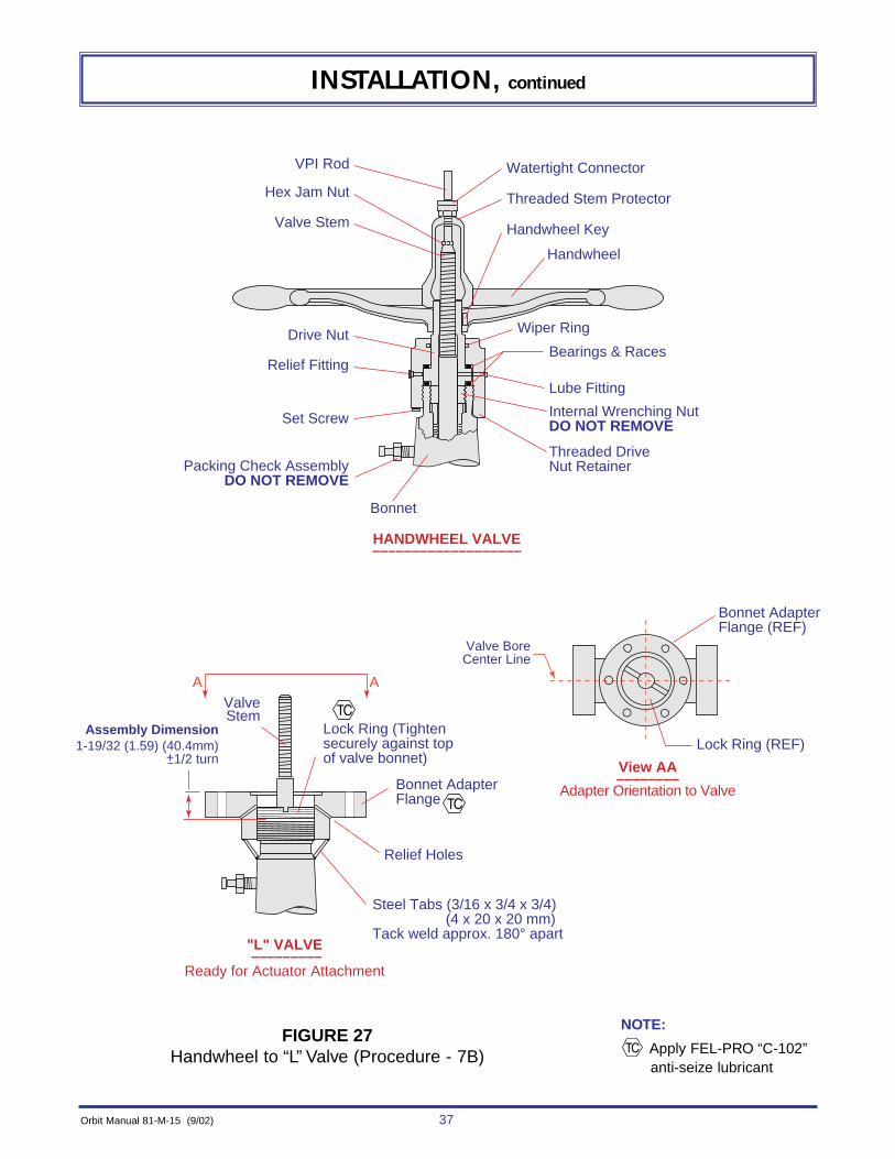
CONVERSION & MOUNTING PROCEDURE - 7B
Refer to Figure 27 for steps 1 through 10.(NOTE: Steps 1 through 10 are omitted if the handwheel assembly has been removed and theadapter assembly has been previously mounted.)
1. Fully open valve with handwheel.
2. Remove the threaded stem protector with the watertight connector.
3. Remove the VPI rod with the hex jam nut.
4. Remove the handwheel and handwheel key.
5. Loosen the set screw and remove the threaded drive nut retainer.
6. Remove the drive nut (left hand threads), bearings, and races.
7. Thread the bonnet adapter flange onto the bonnet and turn it to the specifiedassembly dimension in the figure. Align two of the bolt holes with the valve borecenterline, see view AA.
8. Thread the lock ring into the adapter flange and tighten securely against the top ofthe bonnet. (NOTE: Maintain the proper adapter flange orientation.)
9. Tack weld two user supplied mild steel tabs (approximate size 3/16 x 3/4 x 3/4) (4 x 20 x 20 mm) to the bonnet adapter flange and the valve bonnet, approximately180° apart.
10. Valve is now an “L” valve, as shown, and is ready for actuator attachment.
WARNING: This mounting & conversion procedure is for “PREVIOUS” valve modelswith the closed bonnet configuration, Size & Pressures:
6x6, 8x6 ANSI 900 Class8x8, 10x8 ANSI 400-600 Class10x10, 12x10 ANSI 150-300 Class
BEFORE converting or mounting, be certain this is the correct procedure. Failure to dothis could result in PERSONAL INJURY and/or equipment damage. See pages 11-14for identifying other procedures.
Orbit Manual 81-M-15 (9/02) 37
INSTALLATION, continued
Assembly Dimension1-19/32 (1.59) (40.4mm)
+1/2 turn
A A
HANDWHEEL VALVE–––––––––––––––––––
View AA––––––––
Adapter Orientation to Valve
"L" VALVE –––––––––
Ready for Actuator Attachment
Bearings & Races
Wiper Ring
Watertight Connector
Threaded Stem Protector
Handwheel Key
Handwheel
Bonnet
Internal Wrenching NutDO NOT REMOVE
Threaded Drive Nut Retainer
Lock Ring (Tightensecurely against topof valve bonnet)
Steel Tabs (3/16 x 3/4 x 3/4) (4 x 20 x 20 mm)Tack weld approx. 180° apart
Relief Holes
Bonnet AdapterFlange
Bonnet AdapterFlange (REF)
Lock Ring (REF)
Lube Fitting
Packing Check AssemblyDO NOT REMOVE
VPI Rod
Hex Jam Nut
Valve Stem
ValveStem
Drive Nut
Relief Fitting
Set Screw
Valve BoreCenter Line
FIGURE 27Handwheel to “L” Valve (Procedure - 7B)
NOTE:
Apply FEL-PRO “C-102”anti-seize lubricant
38 Orbit Manual 81-M-15 (9/02)
INSTALLATION, continued
Refer to Figure 28 for steps 11 through 17. (Lubricate as noted in figure.)
11. Thread the actuator unit onto the valve stem (left hand threads) until the distance between the actuator flange and the adapter flange is equal to theassembly dimension for the appropriate actuator. (NOTE: When setting theassembly dimension, the valve is in the full-open position and the actuator is in the full-closed position.)
12. Orientate the actuator to the valve by noting the relationship of the lower gasinlet to the valve bore centerline.
13. Lower the actuator until the actuator flange and adapter flange contact.(NOTE: If they do not contact due to actuator spring compression, apply gaspressure to the lower gas inlet starting at 20 psig (1.4 bars) and increasing bysteps of 5 psig (0.35 bars) until they contact.) (Do not exceed rated pressurestamped on the actuator nameplate.)
14. Install the position indicator plate bracket, bolts, lock washers & nuts, andtighten to 120 ft-lbs (64 Nm) using a criss-cross pattern.
15. Install any accessories, not already installed, to the actuator unit or valve.
16. Lubricate the actuator and check/fill the gas-over-oil tank as described in the “MAINTENANCE” section on page 91. Adjust the spring compression asdetailed in the “SPRING COMPRESSION ADJUSTMENT” section on page54. Install and adjust the visual position indicator plates as detailed in the“INDICATOR PLATES (INSTALLATION & ADJUSTMENT)” section on page 52.
17. The actuator mounting is complete.
CAUTION:Be sure hands and tools are not between the actuator flange and the valve adapter flange, as the actuator will move quickly to make
contact with the valve adapter flange.

Orbit Manual 81-M-15 (9/02) 39
INSTALLATION, continued
FIGURE 28Actuator Mounting (Procedure - 7B)
NOTES:
Apply FEL-PRO “C-102” anti-seize lubricant
Lubricate threads with Lubriplate “930-AA”prior to assembly
Assembly DimensionLS-124-D-4LS-185-D-4 3-9/16 (3.56) (90mm) +3/32 (.09 ) (2.4mm) LS-124-D-25LS-185-D-25 3-11/16 (3.69) (94mm) +3/32(.09) (2.4mm)
Actuator
Actuator Outline Bolt Holes Gas OverOil Tank
Lower Gas Inlet
Actuator Flange
Bolts, Lockwashersand NutsTorque = 120 ft-lbs (163 Nm)
ActuatorShorter End Up
Lower Gas Inlet
ActuatorFlange
Gas OverOil Tank
AdpaterFlange
Lift
ValveStem
Actuator to Valve Orientation ––––––––––
Indicator Plate Bracket Attachment ––––––––––
Assembly Dimensions ––––––––––
Valve BoreCenter Line
Valve PreferredPressure End
Position IndicatorPlate Bracket
PositionIndicator
PlateBracket
Position Indicator
Valve Bonnet

40 Orbit Manual 81-M-15 (9/02)
INSTALLATION, continued
CONVERSION & MOUNTING PROCEDURE - 8B
Refer to Figure 29 for steps 1 through 5.(NOTE: Steps 1 through 5 are omitted if the handwheel assembly has been removed.)
1. Fully open valve with handwheel.
2. Remove the studs, lock-washers & nuts that hold the bearing case & adapter tothe bonnet adapter flange.
3. Remove the entire handwheel and bearing case & adapter assembly as one unitby unscrewing it from the valve stem. (Left hand valve stem threads.) (NOTE: When it comes loose from the valve stem, lift it straight off the VPI rod.)
4. Remove the VPI rod and hex jam nut.
5. Valve is now an “L” valve, as shown, and is ready for actuator attachment.
WARNING: This mounting & conversion procedure is for “PREVIOUS” valve modelswith the O.S.&Y. bonnet configuration, Size & Pressures:
6x6, 8x6 ANSI 900 Class8x8, 10x8 ANSI 400-600 Class10x10, 12x10 ANSI 150-300 Class
BEFORE converting or mounting, be certain this is the correct procedure. Failure to dothis could result in PERSONAL INJURY and/or equipment damage. See pages 11-14for identifying other procedures.

Orbit Manual 81-M-15 (9/02) 41
INSTALLATION, continued
HANDWHEEL VALVE–––––––––––––––––––
"L" VALVE –––––––––
Ready for Actuator Attachment
Handwheel
Hex Jam Nut
Valve Stem
Sleeve
Studs, Lockwashers & Nuts
Welded Tabs
Bonnet Adapter Flange
Packing Gland Retainer
Hex Cap ScrewsDo Not Remove
Bearing Case& Adapter
Drive Nut
Valve Stem
SleeveDo Not Remove
Packing Gland Studs & NutsDo Not Remove
VPI Rod
Indicator Rod Seal
Handwheel Retaining Nut
FIGURE 29Handwheel to “L” Valve (Procedure - 8B)

42 Orbit Manual 81-M-15 (9/02)
INSTALLATION, continued
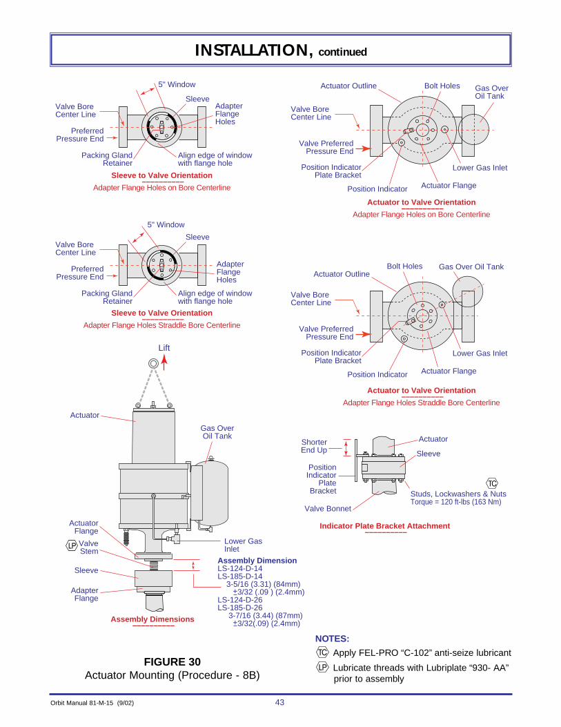
Refer to Figure 30 for steps 6 through 14. (Lubricate as noted in figure.)
6. Orientate the valve sleeve as shown in the figure.
7. Thread the actuator unit onto the valve stem (left hand threads) until the distancebetween the actuator flange and the valve sleeve is equal to the assembly dimen-sion for the appropriate actuator. (NOTE: When setting the assembly dimension,the valve is in the full-open position and the actuator is in the full-closed position.)
8. Orientate the actuator to the valve by noting the relationship of the lower gas inletto the valve bore centerline. (NOTE: Notice the two different orientations, one forvalves with the flange holes on centerline and one for valves with holes straddlingthe centerline.)
9. Lower the actuator until the actuator flange and valve sleeve contact.(NOTE: If they do not contact due to actuator spring compression, apply gaspressure to the lower gas inlet starting at 20 psig (1.4 bars) and increasing bysteps of 5 psig (0.35 bars) until they contact.) (Do not exceed rated pressurestamped on the nameplate for the actuator.)
10. Check that the packing gland nuts on the valve (see Figure 29) are accessiblewith a wrench. If they are not accessible the valve sleeve will need to be rotateduntil they are accessible.
11. Install the position indicator plate bracket, studs, lock washers & nuts, and tight-en to the torque shown in figure 30, using a crisscross pattern.
12. Install any accessories, not already installed, to the actuator unit or valve. Besure the valve packing gland nuts are still accessible.
13. Lubricate the actuator and check/fill the gas-over-oil tank as described in the“MAINTENANCE” section on page 91. Adjust the spring compression as detailedin the “SPRING COMPRESSION ADJUSTMENT” section on page 54. Install andadjust the visual position indicator plates as detailed in the “INDICATOR PLATES (INSTALLATION & ADJUSTMENT)” section on page 52.
14. The actuator mounting is complete.
CAUTION:Be sure hands and tools are not between the actuator flange and
the valve sleeve, as the actuator will move quickly to make contact with the valve sleeve.
Orbit Manual 81-M-15 (9/02) 43
INSTALLATION, continued
FIGURE 30Actuator Mounting (Procedure - 8B)
NOTES:
Apply FEL-PRO “C-102” anti-seize lubricant
Lubricate threads with Lubriplate “930- AA”prior to assembly
Assembly DimensionLS-124-D-14LS-185-D-14 3-5/16 (3.31) (84mm) +3/32 (.09 ) (2.4mm)LS-124-D-26LS-185-D-26 3-7/16 (3.44) (87mm) +3/32(.09) (2.4mm)
Actuator
Actuator Outline Bolt Holes Gas OverOil Tank
Lower Gas Inlet
Actuator Flange
Studs, Lockwashers & NutsTorque = 120 ft-lbs (163 Nm)
Actuator
Sleeve
ShorterEnd Up
Lower Gas Inlet
ActuatorFlange
Gas OverOil Tank
Sleeve
ValveStem
AdapterFlange
Actuator to Valve Orientation ––––––––––
Adapter Flange Holes on Bore Centerline
Sleeve to Valve Orientation ––––––––––
Adapter Flange Holes on Bore Centerline
Indicator Plate Bracket Attachment ––––––––––
Assembly Dimensions ––––––––––
Valve BoreCenter Line
Valve PreferredPressure End
Position IndicatorPlate Bracket
PositionIndicator
PlateBracket
Position Indicator
Valve Bonnet
Valve BoreCenter Line
Sleeve
5" Window
AdapterFlangeHoles
Align edge of windowwith flange hole
Packing GlandRetainer
PreferredPressure End
Actuator OutlineBolt Holes Gas Over Oil Tank
Lower Gas Inlet
Actuator Flange
Actuator to Valve Orientation ––––––––––
Adapter Flange Holes Straddle Bore Centerline
Valve BoreCenter Line
Valve PreferredPressure End
Position IndicatorPlate Bracket
Position Indicator
Valve BoreCenter Line
Sleeve
5" Window
AdapterFlangeHoles
Align edge of windowwith flange hole
Packing GlandRetainer
PreferredPressure End
Sleeve to Valve Orientation ––––––––––
Adapter Flange Holes Straddle Bore Centerline
Lift
44 Orbit Manual 81-M-15 (9/02)
INSTALLATION, continued
CONVERSION & MOUNTING PROCEDURE - 9B
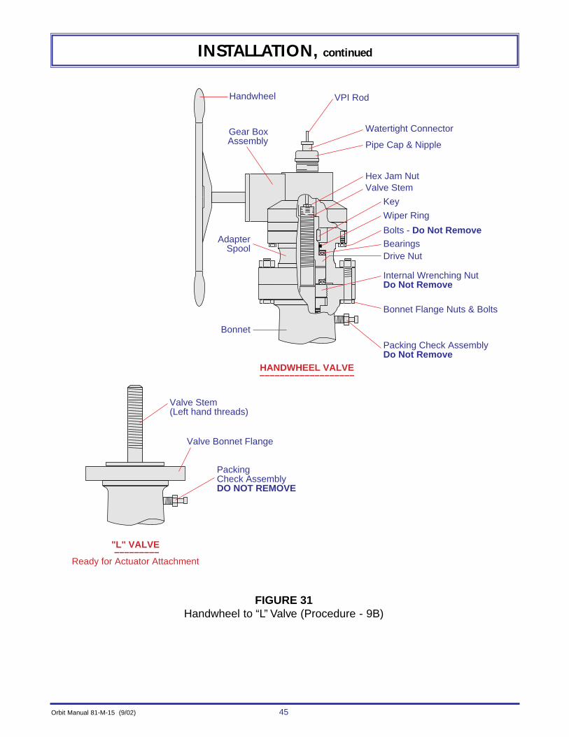
Refer to Figure 31 for steps 1 through 5.(NOTE: Steps 1 through 5 are omitted if the handwheel assembly has been removed.)
1. Fully open valve with the handwheel.
2. Remove the bonnet flange nuts & bolts.
3. Turn the entire gearbox assembly (clockwise) until the unit comes loose from thevalve stem and lift it off (gear box, adapter spool, drive nut with bearings, key andwatertight connector).
4. Remove the VPI rod with the hex jam nut.
5. Valve is now an “L” valve, as shown, and is ready for actuator attachment.
WARNING: This mounting & conversion procedure is for valve model “HC”, Sizes &Pressures:
6x6, 8x6 ANSI 1500-2500 CLASS10x10, 12x10 ANSI 400-600 CLASS12x12, 14x12, 16x12 ANSI 400-600 CLASS
This procedure is also for “PREVIOUS” valve models with the closed bonnet configu-ration, Sizes & Pressures:
10x10, 12x10 ANSI 400-600 CLASS12x12, 14x12, 16x12 ANSI 400-600 CLASS
BEFORE converting or mounting, be certain this is the correct procedure. Failure to dothis could result in PERSONAL INJURY and/or equipment damage. See pages 11-14for identifying other procedures.
Orbit Manual 81-M-15 (9/02) 45
INSTALLATION, continued
FIGURE 31Handwheel to “L” Valve (Procedure - 9B)
HANDWHEEL VALVE–––––––––––––––––––
"L" VALVE –––––––––
Ready for Actuator Attachment
Valve Stem(Left hand threads)
Gear BoxAssembly
AdapterSpool
Bonnet
Handwheel VPI Rod
Watertight Connector
Pipe Cap & Nipple
Hex Jam NutValve Stem
Key
Wiper Ring
Bearings
Bolts - Do Not Remove
Drive Nut
Internal Wrenching NutDo Not Remove
Bonnet Flange Nuts & Bolts
Packing Check AssemblyDo Not Remove
Valve Bonnet Flange
PackingCheck AssemblyDO NOT REMOVE

46 Orbit Manual 81-M-15 (9/02)
INSTALLATION, continued
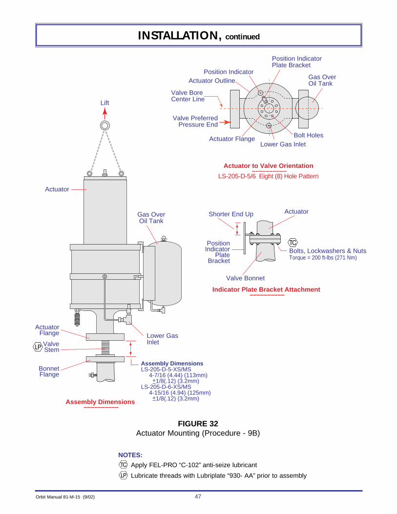
Refer to Figure 32 for steps 6 through 12. (Lubricate as noted in figure.)6. Thread the actuator unit onto the valve stem (left hand threads) until the dis-
tance between the actuator flange and the valve bonnet flange is equal to theassembly dimension for the appropriate actuator.(NOTE: When setting the assembly dimension, the valve is in the full-openposition and the actuator is in the full-closed position.)
7. Orientate the actuator to the valve by noting the relationship of the lower gasinlet to the valve bore centerline.
8. Lower the actuator until the actuator flange and valve bonnet flange contact.(NOTE: If they do not contact due to actuator spring compression, apply gaspressure to the lower gas inlet starting at 20 psig (1.4 bars) and increasing bysteps of 5 psig (0.35 bars) until they contact.) (Do not exceed rated pressurestamped on actuator nameplate.)
9. Install indicator plate bracket, bolts, lock washers & nuts, and tighten to theproper torque using a criss-cross pattern. (Torque = 200 ft-lbs (271 Nm).)
10. Install any accessories, not already installed, to the actuator unit or valve.
11. Lubricate the actuator and check/fill the gas-over-oil tank as described in the“MAINTENANCE” section on page 91. Adjust the spring compression asdetailed in the “SPRING COMPRESSION ADJUSTMENT” section on page54. Install and adjust the visual position indicator plates as detailed in the“INDICATOR PLATES (INSTALLATION & ADJUSTMENT)” section on page 52.
12. The actuator mounting is complete.
CAUTION:Be sure hands and tools are not between the actuator flange and the valve bonnet flange, as the actuator will move quickly to make
contact with the valve bonnet flange.
Orbit Manual 81-M-15 (9/02) 47
INSTALLATION, continued
FIGURE 32Actuator Mounting (Procedure - 9B)
NOTES:
Apply FEL-PRO “C-102” anti-seize lubricant
Lubricate threads with Lubriplate “930- AA” prior to assembly
Assembly DimensionsLS-205-D-5-XS/MS 4-7/16 (4.44) (113mm) +1/8(.12) (3.2mm)LS-205-D-6-XS/MS 4-15/16 (4.94) (125mm) +1/8(.12) (3.2mm)
Actuator
Bolts, Lockwashers & NutsTorque = 200 ft-lbs (271 Nm)
ActuatorShorter End Up
Lower Gas Inlet
ActuatorFlange
Gas OverOil Tank
Lift
ValveStem
BonnetFlange
Indicator Plate Bracket Attachment ––––––––––
Assembly Dimensions ––––––––––
PositionIndicator
PlateBracket
Valve Bonnet
Actuator Outline
Bolt Holes
Gas OverOil Tank
Lower Gas InletActuator Flange
Actuator to Valve Orientation ––––––––––
LS-205-D-5/6 Eight (8) Hole Pattern
Valve BoreCenter Line
Valve PreferredPressure End
Position IndicatorPlate Bracket
Position Indicator

48 Orbit Manual 81-M-15 (9/02)
INSTALLATION, continued
CONVERSION & MOUNTING PROCEDURE - 10B
Refer to Figure 33 for steps 1 through 5.(NOTE: Steps 1 through 5 are omitted if the handwheel assembly has been removed.)
1. Fully open valve with the handwheel.
2. Remove the studs, lock washers & nuts that hold the spool to the sleeve.
3. Remove the entire gear box and adapter spool assembly as one unit byunscrewing it from the valve stem. (Left hand valve stem threads.) (NOTE: When it comes loose from the valve stem, lift it straight off the VPI rod.)
4. Remove the VPI rod with the hex jam nut.
5. Valve is now an “L” valve, as shown, and is ready for actuator attachment.
WARNING: This mounting & conversion procedure is for valve model “HD”. Sizes &Pressures:
8x8, 10x8 ANSI 900 Class10x10, 12x10 ANSI 400-900 Class12x12, 14x12, 16x12 ANSI 400-600 Class
This procedure is also for “PREVIOUS” valve models with the OS&Y bonnet configu-ration. Sizes & Pressures:
8x8, 10x8 ANSI 900 Class 10x10, 12x10 ANSI 400-900 Class 12x12, 14x12, 16x12 ANSI 400-600 Class
BEFORE converting or mounting, be certain this is the correct procedure. Failure to dothis could result in PERSONAL INJURY and/or equipment damage. See pages 11-14for identifying other procedures.

Orbit Manual 81-M-15 (9/02) 49
INSTALLATION, continued
FIGURE 33Handwheel to “L” Valve (Procedure - 10B)
Valve Stem
Sleeve
HANDWHEEL VALVE–––––––––––––––––––
"L" VALVE –––––––––
Ready for Actuator Attachment
Gear BoxAssembly
Watertight Connector
Special Pipe Plug
VPI Rod
Adapter Spool
Bonnet Flange
Valve Stem
SleeveDo Not Remove
Handwheel
Hex Jam Nut
Retainer NutDo Not Remove
Packing GlandStuds & NutsDo Not Remove
Packing GlandRetainer
BoltsDo Not Remove
Studs,Lock Washers
& Nuts
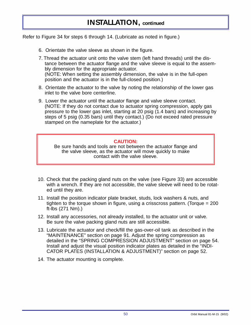
50 Orbit Manual 81-M-15 (9/02)
INSTALLATION, continued
Refer to Figure 34 for steps 6 through 14. (Lubricate as noted in figure.)
6. Orientate the valve sleeve as shown in the figure.
7. Thread the actuator unit onto the valve stem (left hand threads) until the dis-tance between the actuator flange and the valve sleeve is equal to the assem-bly dimension for the appropriate actuator.(NOTE: When setting the assembly dimension, the valve is in the full-open position and the actuator is in the full-closed position.)
8. Orientate the actuator to the valve by noting the relationship of the lower gasinlet to the valve bore centerline.
9. Lower the actuator until the actuator flange and valve sleeve contact.(NOTE: If they do not contact due to actuator spring compression, apply gaspressure to the lower gas inlet, starting at 20 psig (1.4 bars) and increasing bysteps of 5 psig (0.35 bars) until they contact.) (Do not exceed rated pressurestamped on the nameplate for the actuator.)
10. Check that the packing gland nuts on the valve (see Figure 33) are accessiblewith a wrench. If they are not accessible, the valve sleeve will need to be rotat-ed until they are.
11. Install the position indicator plate bracket, studs, lock washers & nuts, andtighten to the torque shown in figure, using a crisscross pattern. (Torque = 200ft-lbs (271 Nm).)
12. Install any accessories, not already installed, to the actuator unit or valve.Be sure the valve packing gland nuts are still accessible.
13. Lubricate the actuator and check/fill the gas-over-oil tank as described in the“MAINTENANCE” section on page 91. Adjust the spring compression asdetailed in the “SPRING COMPRESSION ADJUSTMENT” section on page 54.Install and adjust the visual position indicator plates as detailed in the “INDI-CATOR PLATES (INSTALLATION & ADJUSTMENT)” section on page 52.
14. The actuator mounting is complete.
CAUTION:Be sure hands and tools are not between the actuator flange and
the valve sleeve, as the actuator will move quickly to make contact with the valve sleeve.

Orbit Manual 81-M-15 (9/02) 51
INSTALLATION, continued
FIGURE 34Actuator Mounting (Procedure - 10B)
NOTES:
Apply FEL-PRO “C-102” anti-seize lubricant
Lubricate threads with Lubriplate “930- AA” prior to assembly
Assembly DimensionLS-205-D-15-XS/MS 4-3/16 (4.19) (106mm) +1/8 (.12 ) (3.2mm)LS-205-D-16-XS/MS 4-11/16 (4.69) (119mm) +1/8 (.12) (3.2mm)
Actuator
Studs, Lockwashers & NutsTorque = 200 ft-lbs (271 Nm)
Actuator
Sleeve
ShorterEnd Up
Lower Gas Inlet
ActuatorFlange
Gas OverOil Tank
Sleeve
ValveStem
AdapterFlange
Indicator Plate Bracket Attachment ––––––––––
Assembly Dimensions ––––––––––
PositionIndicator
PlateBracket
Valve Bonnet
C L
Actuator Outline
Bolt Holes
Gas OverOil Tank
Lower Gas InletActuator Flange
Actuator to Valve Orientation ––––––––––
Valve BoreCenter Line
Valve PreferredPressure End
Position IndicatorPlate Bracket
Position Indicator
Sleeve to Valve Orientation ––––––––––
Valve BoreCenter Line
Sleeve6" Window
FlangeHoles
Align edge of window with centerline of Packing Gland Retainer
Packing GlandRetainer
PreferredPressure End
Lift

52 Orbit Manual 81-M-15 (9/02)
INSTALLATION, continued
INDICATOR PLATES (INSTALLATION & ADJUSTMENT)
Refer to Figure 35.1. Cycle the valve to the full open or full closed position.
2. Attach the corresponding plate with self-tapping screws so the pointer isover the bright band.
3. To determine if the valve is achieving full travel, measure the stroke of thepointer on the open & closed indicator plates. See NOMINAL VALVESTROKE CHART, next page, for approximate nominal valve travel.
NOTE: During the life of the valve, the stem travel will increase, thus causing the “closed” indicator plate to require readjustment
to compensate for this additional travel.
FIGURE 35Indicator Plate Adjustment
OPEN
CLOSED
Pointer
OPEN POSITIONBright Band
Self TappingScrews
IndicatorPlate
BracketCLOSED POSITION
Visual Position Indicator Rod (VPI)
NominalValveTravel
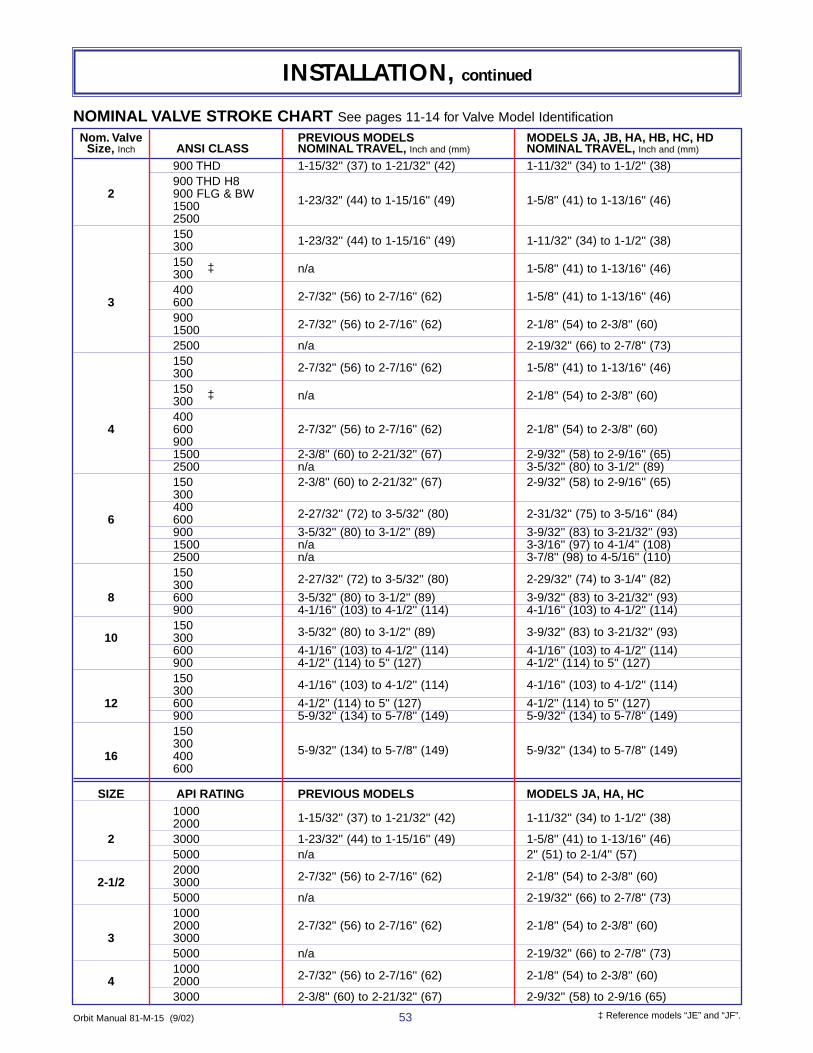
Orbit Manual 81-M-15 (9/02) 53
INSTALLATION, continued
NOMINAL VALVE STROKE CHART See pages 11-14 for Valve Model Identification
Nom. Valve PREVIOUS MODELS MODELS JA, JB, HA, HB, HC, HDSize, Inch ANSI CLASS NOMINAL TRAVEL, Inch and (mm) NOMINAL TRAVEL, Inch and (mm)
900 THD 1-15/32'' (37) to 1-21/32'' (42) 1-11/32'' (34) to 1-1/2'' (38)900 THD H8
2 900 FLG & BW 1-23/32" (44) to 1-15/16'' (49) 1-5/8'' (41) to 1-13/16'' (46)15002500150 1-23/32'' (44) to 1-15/16'' (49) 1-11/32'' (34) to 1-1/2'' (38)300 150 n/a 1-5/8'' (41) to 1-13/16'' (46)300 ‡
400 2-7/32'' (56) to 2-7/16'' (62) 1-5/8'' (41) to 1-13/16'' (46)3 600900 2-7/32'' (56) to 2-7/16'' (62) 2-1/8'' (54) to 2-3/8'' (60)15002500 n/a 2-19/32'' (66) to 2-7/8'' (73)150 2-7/32'' (56) to 2-7/16'' (62) 1-5/8'' (41) to 1-13/16'' (46)300150 n/a 2-1/8'' (54) to 2-3/8'' (60)300 ‡
4004 600 2-7/32'' (56) to 2-7/16'' (62) 2-1/8'' (54) to 2-3/8'' (60)
9001500 2-3/8'' (60) to 2-21/32'' (67) 2-9/32'' (58) to 2-9/16'' (65)2500 n/a 3-5/32'' (80) to 3-1/2'' (89)150 2-3/8'' (60) to 2-21/32'' (67) 2-9/32'' (58) to 2-9/16'' (65)300400 2-27/32'' (72) to 3-5/32'' (80) 2-31/32'' (75) to 3-5/16'' (84)6 600900 3-5/32'' (80) to 3-1/2'' (89) 3-9/32'' (83) to 3-21/32'' (93)1500 n/a 3-3/16'' (97) to 4-1/4'' (108)2500 n/a 3-7/8'' (98) to 4-5/16'' (110)150 2-27/32'' (72) to 3-5/32'' (80) 2-29/32'' (74) to 3-1/4'' (82)300
8 600 3-5/32'' (80) to 3-1/2'' (89) 3-9/32'' (83) to 3-21/32'' (93)900 4-1/16'' (103) to 4-1/2'' (114) 4-1/16'' (103) to 4-1/2'' (114)150 3-5/32'' (80) to 3-1/2'' (89) 3-9/32'' (83) to 3-21/32'' (93)10 300600 4-1/16'' (103) to 4-1/2'' (114) 4-1/16'' (103) to 4-1/2'' (114)900 4-1/2'' (114) to 5'' (127) 4-1/2'' (114) to 5'' (127)150 4-1/16'' (103) to 4-1/2'' (114) 4-1/16'' (103) to 4-1/2'' (114)300
12 600 4-1/2'' (114) to 5'' (127) 4-1/2'' (114) to 5'' (127)900 5-9/32'' (134) to 5-7/8'' (149) 5-9/32'' (134) to 5-7/8'' (149)150300 5-9/32'' (134) to 5-7/8'' (149) 5-9/32'' (134) to 5-7/8'' (149)16 400600
SIZE API RATING PREVIOUS MODELS MODELS JA, HA, HC1000 1-15/32'' (37) to 1-21/32'' (42) 1-11/32'' (34) to 1-1/2'' (38)2000
2 3000 1-23/32'' (44) to 1-15/16'' (49) 1-5/8'' (41) to 1-13/16'' (46)5000 n/a 2'' (51) to 2-1/4'' (57)2000 2-7/32'' (56) to 2-7/16'' (62) 2-1/8'' (54) to 2-3/8'' (60)2-1/2 30005000 n/a 2-19/32'' (66) to 2-7/8'' (73)10002000 2-7/32'' (56) to 2-7/16'' (62) 2-1/8'' (54) to 2-3/8'' (60)
3 30005000 n/a 2-19/32'' (66) to 2-7/8'' (73)1000 2-7/32'' (56) to 2-7/16'' (62) 2-1/8'' (54) to 2-3/8'' (60)4 20003000 2-3/8'' (60) to 2-21/32'' (67) 2-9/32'' (58) to 2-9/16 (65)
‡ Reference models “JE” and “JF”.

54 Orbit Manual 81-M-15 (9/02)
INSTALLATION, continued
SPRING COMPRESSION ADJUSTMENTAdjustment of the spring compression is critical for the proper operation of a valve with a
spring-close actuator. The spring adjustment is done with the actuator attached to the valve,with the valve de-pressurized, and an accurate pressure gauge (0-100 psig, 0-10 bars). Theadjustment is done as follows:
I. NON-ADJUSTABLE TYPE SPRING ADJUSTMENT (ACME THREADED STEM) TYPE NProper adjustment of the spring is achieved by turning the handwheel until the hole in the
stem lines up with the thru hole in the debris cover. The lock pin is then inserted and cotter hairpin installed. Refer to figure 36.
II. ADJUSTABLE TYPE SPRING ADJUSTMENT Refer to figure 36.
1. Loosen jam nut. (LS-205 with manual two-way mechanism does not have a jam nut).2. Be sure spring compression is released by turning the spring adjusting screw or
handwheel counter clockwise to at least the dimension shown in the table below:
3. Open the valve using the gas (air) pressure indicated on the valve/actuator name-plate. Usually 75-80 psig (5.1 - 5.5 bars).
4. Mark the position of the pointer on the visual position indicator plate bracket.(NOTE: If the open indicator plate is attached, it can be adjusted to show this posi-tion.) This gives the fulI open position of the valve.
5. Bleed the gas (air) pressure from actuator.6. Make a rough spring setting by turning the spring adjustment screw or handwheel
clockwise to the direction shown in the “Rough Spring Setting Chart” below:
Actuator Size “A” “B”Inch (mm) Inch (mm)
LS-124 7'' (178) 11'' (279)LS-185 9'' (229) 14'' (356) LS-205 10'' (254) 4'' (102)
ROUGH SETTING CHART - Set Dimension +1/4 (.25) (6 mm)
Actuator Size “A’’ “B’’Inch (decimal) (mm) Inch (decimal) (mm)
LS-124 D-2/12/21/22 4-9/16'' (4.56) (116) 8-9/16'' (8.56) (217)D-3/4/13/14/23/24/25/26 5-1/4'' (5.25) (133) 9-1/4'' (9.25) (235 mm)D-20 4-11/16'' (4.69 (119) 8-11/16'' (8.69) (221)D-27 4-3/16'' (4.19)(106) 9-3/16'' (8.19) (208)l
LS-185-D-4/25 6'' (6.00) (152) 11-7/16'' (11.44) (291)D-14/26 5-3/4'' (5.75) (146) 11-3/16'' (11.19) (284)D-5 6-7/8'' (6.88) (175) 12-5/16'' (12.31) (313)D15 6-5/8'' (6.62) (168) 12-1/16'' (12.06) (306)D-20 5-7/16'' (5.44) (138) 10-7/8''(10.88) (276)
LS-205-D-5 6-1/8'' (6.12) (155) 1/2'' (.50) (13)D-6 6-5/8'' (6.62) (168) 1'' (1.00) (25)D-15 5-7/8'' (5.88) (149) 1/4'' (.25) (6)D-16 6-3/8'' (6.38) (162) 3/4'' (.75) (19)D-26 7-1/4'' (7.25) (184)

Orbit Manual 81-M-15 (9/02) 55
INSTALLATION, continued
OPEN
CLOSED
CotterHair Pin
Handwheel
Handwheel
Handwheel
Visual PositionIndicator Plate(Mark on bracket
if plate is notattached)
Neutral PositionIndicator Rod
"B" Dimension
NeutralPositionIndicator(Bend to
adjust)
Jam Nut
Stem
Stem Boot
Debris Cover
Lock Pin
Spring Close with Two-WayManual Mechanism Type M
––––––––––––––(except LS-205)
Visual Position Indicator––––––––––––––
Spring Close with Two-WayManual Mechanism
––––––––––––––(LS-205 only)
Non-Adjustable Type NACME Threaded Stem
Spring Close w/ Two-Way Manual Mechanism––––––––––––––
(except LS-205)
Spring Close––––––––––––––
(all sizes)
ActuatorSpring
Housing
"B" Dimension
Jam Nut
SpringAdjusting Screw
"A" Dimension
Neutral PositionIndicator
GaugeAdjust so that the
gauge just touches the bottom of the
handwheel when in neutral position
(The gauge is folded down when
the manual mechanism is
used)
Pointer
VisualPositionIndicatorBracket
FIGURE 36Spring Compression Adjustment
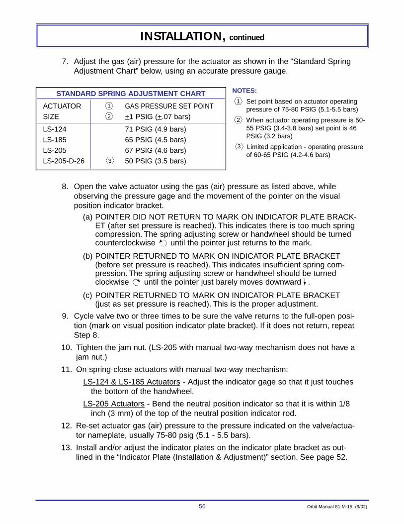
56 Orbit Manual 81-M-15 (9/02)
INSTALLATION, continued
7. Adjust the gas (air) pressure for the actuator as shown in the “Standard SpringAdjustment Chart” below, using an accurate pressure gauge.
STANDARD SPRING ADJUSTMENT CHART
ACTUATOR GAS PRESSURE SET POINT
SIZE +1 PSIG (+.07 bars)
LS-124 71 PSIG (4.9 bars)
LS-185 65 PSIG (4.5 bars)
LS-205 67 PSIG (4.6 bars)
LS-205-D-26 50 PSIG (3.5 bars)3
2
1
NOTES:
Set point based on actuator operatingpressure of 75-80 PSIG (5.1-5.5 bars)
When actuator operating pressure is 50-55 PSIG (3.4-3.8 bars) set point is 46PSIG (3.2 bars)
Limited application - operating pressureof 60-65 PSIG (4.2-4.6 bars)
3
2
1
8. Open the valve actuator using the gas (air) pressure as listed above, whileobserving the pressure gage and the movement of the pointer on the visualposition indicator bracket.
(a) POINTER DID NOT RETURN TO MARK ON INDICATOR PLATE BRACK-ET (after set pressure is reached). This indicates there is too much springcompression. The spring adjusting screw or handwheel should be turnedcounterclockwise until the pointer just returns to the mark.
(b) POINTER RETURNED TO MARK ON INDICATOR PLATE BRACKET(before set pressure is reached). This indicates insufficient spring com-pression. The spring adjusting screw or handwheel should be turnedclockwise until the pointer just barely moves downward .
(c) POINTER RETURNED TO MARK ON INDICATOR PLATE BRACKET(just as set pressure is reached). This is the proper adjustment.
9. Cycle valve two or three times to be sure the valve returns to the full-open posi-tion (mark on visual position indicator plate bracket). If it does not return, repeatStep 8.
10. Tighten the jam nut. (LS-205 with manual two-way mechanism does not have ajam nut.)
11. On spring-close actuators with manual two-way mechanism:
LS-124 & LS-185 Actuators - Adjust the indicator gage so that it just touchesthe bottom of the handwheel.
LS-205 Actuators - Bend the neutral position indicator so that it is within 1/8inch (3 mm) of the top of the neutral position indicator rod.
12. Re-set actuator gas (air) pressure to the pressure indicated on the valve/actua-tor nameplate, usually 75-80 psig (5.1 - 5.5 bars).
13. Install and/or adjust the indicator plates on the indicator plate bracket as out-lined in the “Indicator Plate (Installation & Adjustment)” section. See page 52.
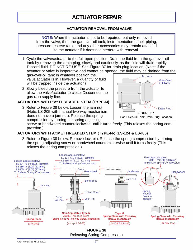
Orbit Manual 81-M-15 (9/02) 57
ACTUATOR REPAIR
ACTUATOR REMOVAL FROM VALVE
1. Cycle the valve/actuator to the full-open position. Drain the fluid from the gas-over-oiltank by removing the drain plug, slowly and cautiously, as the fluid will drain rapidly.Discard fluid. DO NOT RE-USE. See Figure 37 for drain plug location. (Note: If the actuator or valve is inoperative and cannot be opened, the fluid may be drained from thegas-over-oil tank in whatever position thevalve/actuator is in. However, a quantity of fluid will be trapped inside the actuator.)
2. Slowly bleed the pressure from the actuator toallow the valve/actuator to close. Disconnect thegas (air) supply line.
ACTUATORS WITH “V”THREADED STEM (TYPE-M)3. Refer to Figure 38 below. Loosen the jam nut
(Note: LS-205 with manual two-way mechanismdoes not have a jam nut). Release the springcompression by turning the spring adjustingscrew or handwheel counterclockwise until it turns freely. (This relaxes the spring com-pression.)
ACTUATORS WITH ACME THREADED STEM (TYPE-N-) (LS-124 & LS-I85)3. Refer to Figure 38 below. Remove lock pin. Release the spring compression by turning
the spring adjusting screw or handwheel counterclockwise until it turns freely. (Thisrelaxes the spring compression.)
NOTE: When the actuator is not to be repaired, but only removed from the valve, then the gas-over-oil tank, instrumentation panel, piping,pressure reserve tank, and any other accessories may remain attached
to the actuator if it does not interfere with removal.
Gas-OverOil Tank
Drain Plug
Actuator
CotterHair Pin
HandwheelHandwheel Handwheel
SpringNeutralPositionIndicator
Jam Nut
Stem
Stem Boot
Debris Cover
Lock Pin
Type MSpring Close with Two-Way
Manual Mechanism––––––––––––––
(LS-124 & LS-185)
Spring Close with Two-WayManual Mechanism
––––––––––––––(LS-205 only)
Non-Adjustable Type NACME Threaded Stem
Spring Close w/ Two-Way Manual Mechanism––––––––––––––(except LS-205)
Spring Close––––––––––––––
(all sizes)
Jam Nut
Loosen approximately:LS-124 6-1/4" (6.25) (159 mm)LS-185 8" (8.00) (203 mm)LS-205 8" (8.00) (203 mm)
To Relieve Spring Compression
Loosen approximately:LS-124 6-1/4" (6.25) (159 mm)LS-185 8" (8.00) (203 mm)
To Relieve Spring Compression
Rises approximately:LS-205 8" (8.00) (203 mm)
To Relieve Spring Compression
FIGURE 37Gas-Over-Oil Tank Drain Plug Location
FIGURE 38Releasing Spring Compression
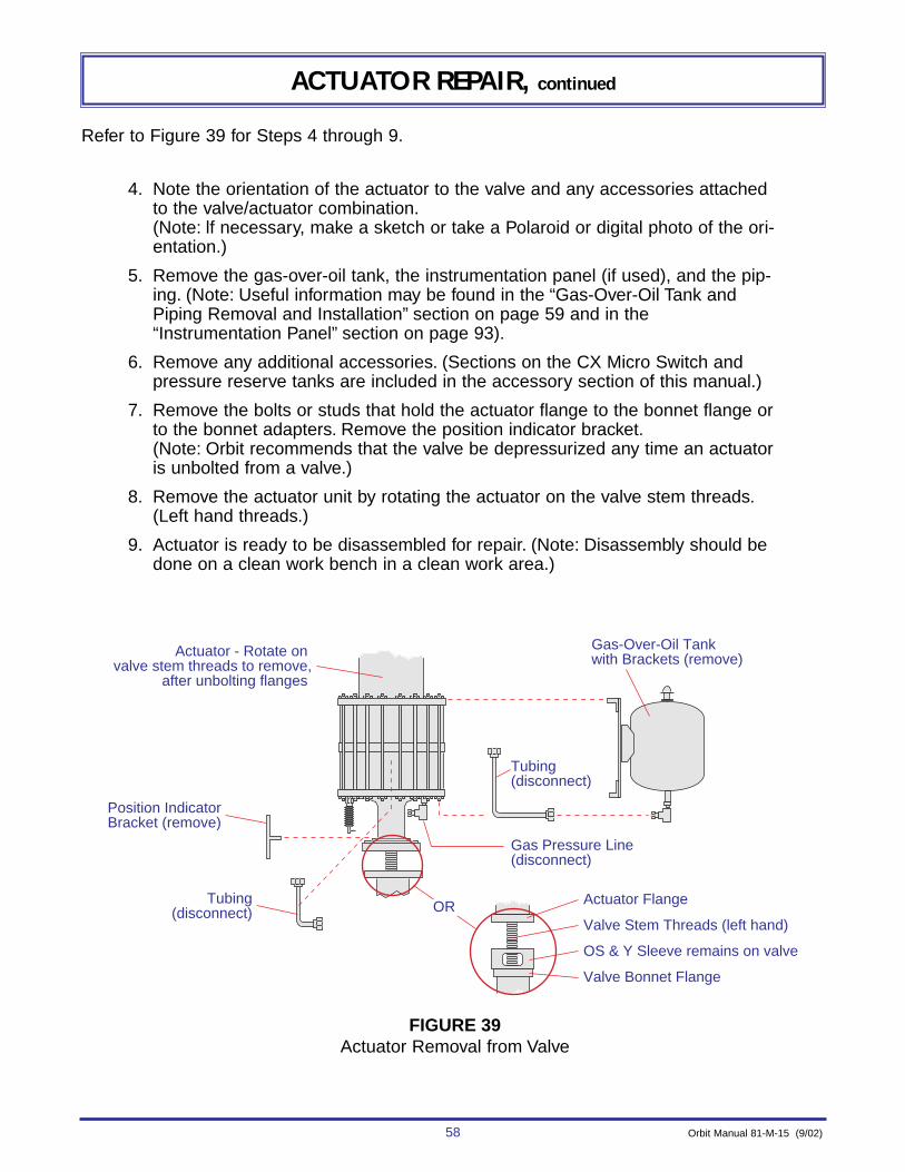
58 Orbit Manual 81-M-15 (9/02)
ACTUATOR REPAIR, continued
Refer to Figure 39 for Steps 4 through 9.
4. Note the orientation of the actuator to the valve and any accessories attachedto the valve/actuator combination.(Note: lf necessary, make a sketch or take a Polaroid or digital photo of the ori-entation.)
5. Remove the gas-over-oil tank, the instrumentation panel (if used), and the pip-ing. (Note: Useful information may be found in the “Gas-Over-Oil Tank andPiping Removal and Installation” section on page 59 and in the“Instrumentation Panel” section on page 93).
6. Remove any additional accessories. (Sections on the CX Micro Switch andpressure reserve tanks are included in the accessory section of this manual.)
7. Remove the bolts or studs that hold the actuator flange to the bonnet flange orto the bonnet adapters. Remove the position indicator bracket.(Note: Orbit recommends that the valve be depressurized any time an actuatoris unbolted from a valve.)
8. Remove the actuator unit by rotating the actuator on the valve stem threads.(Left hand threads.)
9. Actuator is ready to be disassembled for repair. (Note: Disassembly should bedone on a clean work bench in a clean work area.)
Actuator - Rotate on valve stem threads to remove,
after unbolting flanges
Gas-Over-Oil Tankwith Brackets (remove)
Position IndicatorBracket (remove)
Tubing(disconnect)
Tubing(disconnect)
Gas Pressure Line(disconnect)
Actuator Flange
Valve Stem Threads (left hand)
OS & Y Sleeve remains on valve
Valve Bonnet Flange
OR
FIGURE 39Actuator Removal from Valve
Orbit Manual 81-M-15 (9/02) 59
ACTUATOR REPAIR
GAS-OVER-OIL TANK AND PIPING REMOVAL & INSTALLATION
For removal and installation refer to:
Figure 40 for size “LS-124” - page 60
Figure 41 for size “LS-185” - page 61
Figure 42 for size “LS-205” - page 62
REMOVAL1. Drain the fluid from the gas-over-oil tank. (Note: To drain, cycle the valve/actuator to the
full open position. Drain the fluid from the tank by removing the drain plug slowly andcautiously, as the fluid will drain rapidly. Discard fluid. DO NOT REUSE. See figures forthe drain plug location. If the actuator or valve is inoperative, the fluid may be drained inwhatever position the valve/actuator is in, but a quantity of fluid will be trapped insidethe actuator.)
2. Slowly bleed the pressure from the actuator to allow the valve/actuator to close.Disconnect the gas (air) supply line.
3. Remove the piping and tubing. A sketch, Polaroid or digital photo may be helpful forreassembly. (Note: Generally, only the tubing needs to be disconnected. The pipe fittingsand tubing fittings may remain installed, unless damaged or leaking. If optional instru-mentation panel is installed, remove panel as an assembly. See page 93 for panelremoval.)
4. Note the position of the gas-over-oil tank in relation to the lower gas inlet. Remove tank.(NOTE: The figures show the standard tank orientation; however, some tanks may havedifferent orientations to meet special requirements of some customers.)
INSTALLATION
1. Install gas-over-oil tank to actuator. Be sure the orientation to the lower gas inlet is correct.
2. Install tubing and piping. (Install instrumentation panel, if so equipped.)
3. Check that all the bolts, tubing. and pipe fittings are tight.4. Fill the gas-over-oil tank as described in the “MAINTENANCE” section on page 92.
(Note: If the actuator is not mounted to a valve, wait until it is mounted, to fill the tank.)
WARNING:NEVER use thread tape on pipe or tubing fittings.
Use Loctite pipe compound or equivalent.Tape particles can cause internal damage to the actuator instrumentation,
requiring a complete disassembly of the actuator to repair.
NOTE: The tank must be mounted in a vertical and upright position, regardless of the orientation of the valve/actuator. This may require
different brackets and additional fittings for some valve/ actuator orientations.

60 Orbit Manual 81-M-15 (9/02)
ACTUATOR REPAIR, continued
���������������� ���
��
�
�
����
�
�
���
�����
Bottom View ––––––––––
Fluid Level Plug
SpringHousing(Top Hat)
Optional ManualTwo-Way Mechanism
PC1
PC 15
PC 1
L
L
L
1722
2321
17
19
18
18
View AA ––––––––––
Detail C ––––––––––
Detail D ––––––––––
6 16
24
14
11
ASMEData Plate
Drain Plug
PC4PC 8
PC 9
PC 12PC 13
PC 11 PC 3
View BB ––––––––––
20
25
2
5
PC1
PC10
TC7
D
C
B
A
ATop View
––––––––––
TC
B
7
FIGURE 40“LS-124” Standard Gas/Oil
Tank and Piping
ITEM QTY DESCRIPTION1 .........3 ...............3/8" NPT x 1-1/2" Nipple2 .........1 ...............1/2" OD x 3/8" NPT Female Tubing Elbow3 .........1 ...............1/2" OD x 1/2" NPT Male Tubing Connector4 .........1 ...............3/8" NPT Plug, Steel (for shipping)5 .........1 ...............1/2" Tee6 .........1 ...............3/8" NPT Plastic Thread Protector (shipping)7 .........1 ...............1/4" NPT Filter Breather8 .........1 ...............3/8" NPT Breather Cap9 .........1 ...............1" NPT x 3/8" NPT Hex Bushing10 .......1 ...............3/8" NPT Plug11 .......2 ...............1/2" NPT Plug12 .......1 ...............1" NPT x 1/2" NPT Hex Bushing13 .......1 ...............1/2" NPT Oil Deflector14 .......1 ...............3/8" OD x 3/8" NPT Female Tubing Elbow15 .......1 ...............3/8" OD x 3/8" NPT Male Tubing Connector16 .......1 ...............3/8" NPT Tee17 .......8 ...............1/2 x 1-1/4" Hex Head Cap Screw18 .......8 ...............1/2" Heavy Hex Nut19 .......4 ...............1/2" Flat Washer20 .......1 ...............Gas Over Oil Tank (3 Gallon)21 .......2 ...............Angle22 .......1 ..............Plate23 .......2 ..............Spacer24 .......As Req'd...3/8" OD Stainless Steel Tubing25 .......As Req'd...1/2" OD Stainless Steel Tubing
NOTES: Apply Loctite pipe compound to pipe threads only
Apply Loctite No. 262 to threads
Apply FEL-PRO “C-102” anti-seize compound to threads

Orbit Manual 81-M-15 (9/02) 61
ACTUATOR REPAIR, continued
��������
C
�������� ��������
Fluid Level Plug
SpringHousing(Top Hat)
Optional ManualTwo-Way Mechanism
PC13
PC3
PC 1
PC 1
L
L
19
2322
20
View AA ––––––––––
View BB ––––––––––
Detail C ––––––––––
B
B
A
ATop View
––––––––––
TC 6
24
223 Ref.
ASMEData Plate
PC 8
PC 14
PC 9
PC 11PC15
PC7
21
25 5
18
17
12
PC4
PC1
PC10
TC6
Bottom View ––––––––––
16PC
7PC
FIGURE 41“LS-185” Standard Gas/Oil
Tank and Piping
ITEM QTY DESCRIPTION1 .........3 ...............3/8" NPT x 1-1/2" Nipple2 .........1 ...............1/2" OD x 3/8" NPT Female Tubing Elbow3 .........1 ...............1/2" OD x 3/8" NPT Male Tubing Connector4 .........1 ...............3/4" NPT Plug, Steel (for shipping)5 .........1 ...............3/8" NPT Plastic Thread Protector (shipping)6 .........1 ...............1/4" NPT Filter Breather7 .........2 ...............3/4" OD x 1/2" NPT Male Tubing Connector8 .........1 ...............3/8" NPT Breather Cap9 .........1 ...............1" NPT Oil Deflector10 .......1 ...............3/8" NPT Plug11 .......1 ...............1" NPT Plug12 .......1 ...............1" NPT Tee13 .......2 ...............1/2" NPT Plug14 .......1 ...............1" NPT x 3/4" NPT Hex Bushing15 .......1 ...............1" NPT x 1/2" NPT Hex Bushing16 .......1 ...............1/2" NPT x 3/8" NPT Hex Bushing17 .......1 ...............1/2" NPT Elbow18 .......1 ...............3/8" NPT Tee19 .......4 ...............1/2" x 1-1/4" Hex Cap Screw20 .......4 ...............1/2" Hex Nut21 .......1 ...............Gas-Over-Oil Tank (8 Gallon)22 .......2 ..............Angle23 .......2 ..............Spacer24 .......As Req'd...1/2" OD Stainless Steel Tubing25 .......As Req'd...3/4" OD Stainless Steel Tubing
NOTES: Apply Loctite pipe compound to pipe threads only
Apply Loctite No. 262 to threads
Apply FEL-PRO “C-102” anti-seize compound to threads

62 Orbit Manual 81-M-15 (9/02)
ACTUATOR REPAIR, continued
C
�������������� ����
����
Fluid Level Plug
SpringHousing(Top Hat)
Optional Two-WayManual Mechanism
PC10
PC1
PC1PC 2
PC 2
TC 5
TC 5
12 3
View AA ––––––––––
View BB ––––––––––
20
13
ASMEData Plate
PC 7
PC 6
PC 1
PC 9
PC 11
17
8
13
PC4
PC10
PC2
PC14
PC2
20
Bottom View ––––––––––
L
L
15
19
17 Ref
18
16
Detail C ––––––––––
B
B
A
ATop View
––––––––––
FIGURE 42“LS-205” Standard Gas/Oil
Tank and Piping
ITEM QTY DESCRIPTION1 .........3 ...............1/2" NPT x 1-1/2" Nipple2 .........4 ...............3/4" OD x 1/2" NPT Male Tubing Connector3 .........1 ...............1/2" NPT Tee4 .........1 ...............3/4" NPT Plug, Steel (for shipping)5 .........1 ...............1/4" NPT Filter Breather6 .........1 ...............1" NPT x 3/4" NPT Hex Bushing7 .........1 ...............3/4" NPT Breather Cap8 .........1 ...............1" NPT Tee9 .........1 ...............1" NPT Oil Deflector10 .......1 ...............1/2" NPT Plug11 .......1 ...............1" NPT Plug12 .......1 ...............1/2" NPT Plastic Thread Protector (shipping)13 .......2 ...............1/2" NPT Elbow14 .......1 ...............1" NPT x 1/2" NPT Hex Bushing15 .......4 ...............1/2" x 1-1/4" Hex Cap Screw16 .......4 ...............1/2" Heavy Hex Nut17 .......1 ...............Gas-Over-Oil Tank (8 Gallon)18 .......2 ...............Angle19 .......2 ...............Spacer20 .......As Req'd...3/4" OD Stainless Steel Tubing
NOTES: Apply Loctite pipe compound to pipe threads only
Apply Loctite No. 262 to threads
Apply FEL-PRO “C-102” anti-seize compound to threads

Orbit Manual 81-M-15 (9/02) 63
ACTUATOR REPAIR, continued
DISASSEMBLY OF SPRING-CLOSE ACTUATOR (LS-124/185/205)
The following procedure describes the complete disassembly of the actuator. Orbit recom-mends removing the actuator from the valve for any internal repairs. However, some internalrepairs may be done while the actuator is attached to the valve. Extra safety precautions mustbe observed to prevent the spring from unexpectedly expanding, causing personal injury andequipment damage. These precautions are: (to be done in order),
a) Close valve. (Note: The valve may tend to open due to pressure in the valve bodyas the spring compression is released or as the actuator is removed.)
b) Be sure the gas (air) pressure to the actuator has been reduced to atmospheric andis maintained there. (Note: It is recommended that the pressure supply line be dis-connected.)
c) Loosen the jam nut and turn the spring adjusting screw counterclockwise until itturns freely or the dimension shown in Figure 43 below is reached.(Note: On LS-124 models, the screw may come loose from the spring case.)
d) Refer to Figure 43. Remove four (4) studs and install new, longer all-thread studswith nuts, (3 inches (76 mm) minimum longer than existing studs.) Remove theremaining shorter studs. Evenly loosen the nuts on the new longer studs so anyremaining spring compression will be released.
Jam Nut
Minimum additionalThreaded Stud Length3 Inches (76 mm)
Spring CaseStud
Nut
Loosen approximately:LS-124 6-1/4" (6.25) (159 mm) (Screw may come loose
from spring case)LS-185 8" (8.00) (203 mm)LS-205 8" (8.00) (203 mm)
To Reduce Spring Compression
Remove these (4) Studs and install new, longer all-thread studs with nuts, as shown. Remove other studs; then evenly loosen the nuts on the new longer studs
Spring Adjusting Screw. Turn counterclockwise to remove spring compression, after loosening the jam nut.
FIGURE 43Removing Spring Case When Actuator is Attached to the Valve.
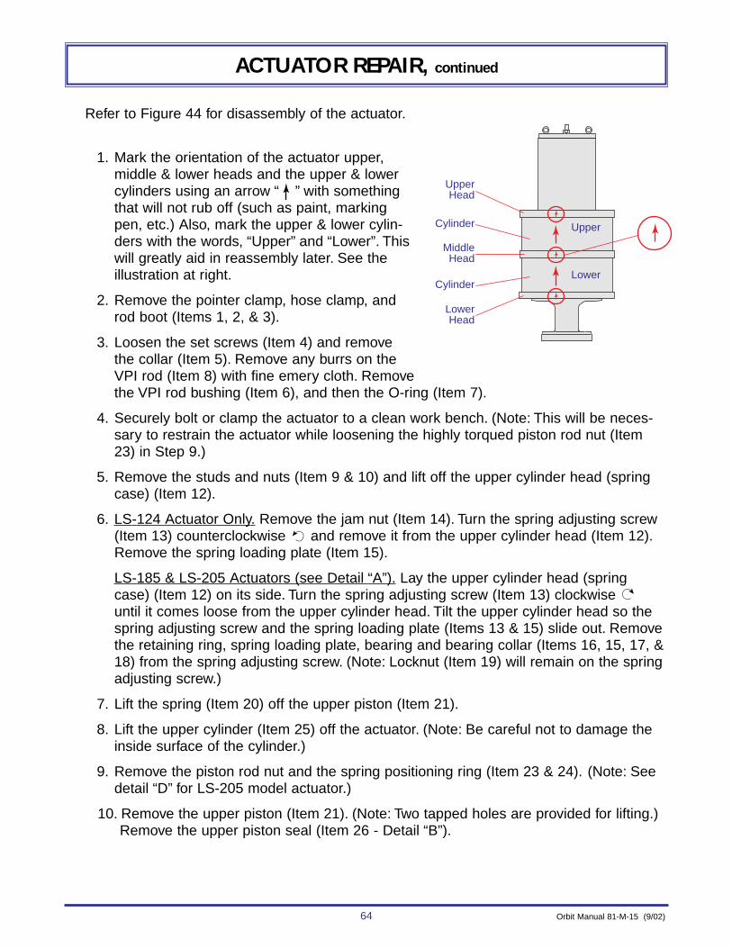
64 Orbit Manual 81-M-15 (9/02)
ACTUATOR REPAIR, continued
Refer to Figure 44 for disassembly of the actuator.
1. Mark the orientation of the actuator upper,middle & lower heads and the upper & lowercylinders using an arrow “ ” with somethingthat will not rub off (such as paint, markingpen, etc.) Also, mark the upper & lower cylin-ders with the words, “Upper” and “Lower”. Thiswill greatly aid in reassembly later. See theillustration at right.
2. Remove the pointer clamp, hose clamp, androd boot (Items 1, 2, & 3).
3. Loosen the set screws (Item 4) and removethe collar (Item 5). Remove any burrs on theVPI rod (Item 8) with fine emery cloth. Removethe VPI rod bushing (Item 6), and then the O-ring (Item 7).
4. Securely bolt or clamp the actuator to a clean work bench. (Note: This will be neces-sary to restrain the actuator while loosening the highly torqued piston rod nut (Item23) in Step 9.)
5. Remove the studs and nuts (Item 9 & 10) and lift off the upper cylinder head (springcase) (Item 12).
6. LS-124 Actuator Only. Remove the jam nut (Item 14). Turn the spring adjusting screw(Item 13) counterclockwise and remove it from the upper cylinder head (Item 12).Remove the spring loading plate (Item 15).
LS-185 & LS-205 Actuators (see Detail “A”). Lay the upper cylinder head (springcase) (Item 12) on its side. Turn the spring adjusting screw (Item 13) clockwise until it comes loose from the upper cylinder head. Tilt the upper cylinder head so thespring adjusting screw and the spring loading plate (Items 13 & 15) slide out. Removethe retaining ring, spring loading plate, bearing and bearing collar (Items 16, 15, 17, &18) from the spring adjusting screw. (Note: Locknut (Item 19) will remain on the springadjusting screw.)
7. Lift the spring (Item 20) off the upper piston (Item 21).
8. Lift the upper cylinder (Item 25) off the actuator. (Note: Be careful not to damage theinside surface of the cylinder.)
9. Remove the piston rod nut and the spring positioning ring (Item 23 & 24). (Note: Seedetail “D” for LS-205 model actuator.)
10. Remove the upper piston (Item 21). (Note: Two tapped holes are provided for lifting.) Remove the upper piston seal (Item 26 - Detail “B”).
UpperHead
Upper
Lower
MiddleHead
LowerHead
Cylinder
Cylinder
Orbit Manual 81-M-15 (9/02) 65
ACTUATOR REPAIR, continued
11. Lift the middle cylinder head off and remove the piston rod sleeve (Items 27 &28). (Note: If the middle cylinder head and sleeve come off together, separatethem after removal from the actuator. Two tapped holes in the middle cylinderhead are provided for lifting. The pipe and tubing fittings may remain in placeunless damaged.) Remove the O-rings (Items 29, 30 & 44).
12. Remove the lower piston with the VPI rod assembly (Items 31 & 8). Remove thelower cylinder (Item 32). Remove the lower piston seal (Item 26 - see detail “B”).and the cylinder O-ring (Item 29 - see detail “C”). Unscrew the VPI rod from thelower piston.
NOTES:(a) Two tapped holes in the lower piston are provided for lifting.
(b) Be careful not to damage the inside surface of the cylinder.
(c) If the lower piston and the lower cylinder come off together, separatethem after removing from the actuator.
(d) The VPI rod may require heating with a propane torch to 350°F(177°C) for a few minutes to degrade the Loctite on the threads.
13. Remove the retaining ring (Item 33).
14. Using the piston rod (Item 22), pop out the sealing gland (Item 34). Slide thesealing gland over the top of the piston rod. Remove the inner and outer O-rings(Items 35 & 36), then remove the key (Item 37).
15. Remove, only if damaged, the lifting lugs and the filter/ breather (Items 38 & 39)from the upper cylinder head (spring case).
16. Remove, only if damaged, the lube (and relief) fitting (Item 41) from the lowercylinder head (Item 40). (Note: Pipe and tubing fittings may remain in the lowercylinder head, unless damaged.)
17. Remove two (2) drive screws and nameplate (Items 42 & 43) only if (a) dam-aged, (b) replacing middle cylinder head, or (c) making changes to the name-plate. See detail “E”.
18. Clean and inspect parts. (Note: Orbit recommends replacing all O-rings andseals, any time an actuator is disassembled, to prevent future unscheduledrepairs because of an O-ring that appeared good.)
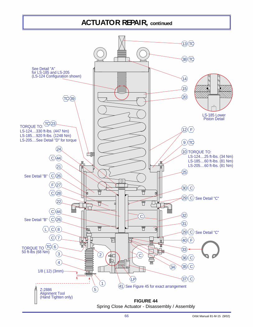
See Detail "A"for LS-185 and LS-205(LS-124 Configuration shown)
TORQUE TO:LS-124....330 ft-lbs. (447 Nm)LS-185....920 ft-lbs. (1248 Nm)LS-205....See Detail "D" for torque
TORQUE TO:LS-124....25 ft-lbs. (34 Nm)LS-185....60 ft-lbs. (81 Nm)LS-205....60 ft-lbs. (81 Nm)
See Detail "B"
TC13
TC38
TC 39
C 44
C 26
F 27
TC 23
24
21
14
15
20
22
3
51
4
See Detail "B"
TORQUE TO50 ft-lbs (68 Nm)
Z-2886Alignment Tool(Hand Tighten only)
See Figure 45 for exact arrangement
See Detail "C"
1/8 (.12) (3mm)
C 26
CL 8
C 28
C 44
C 7
TC 6
41
34
2
LP C
C
C
37
C35
C36
F40
C29
See Detail "C"
LS-185 LowerPiston Detail
C29
C30
TC9
F12
25
10
33
31
32
66 Orbit Manual 81-M-15 (9/02)
ACTUATOR REPAIR, continued
FIGURE 44Spring Close Actuator - Disassembly / Assembly
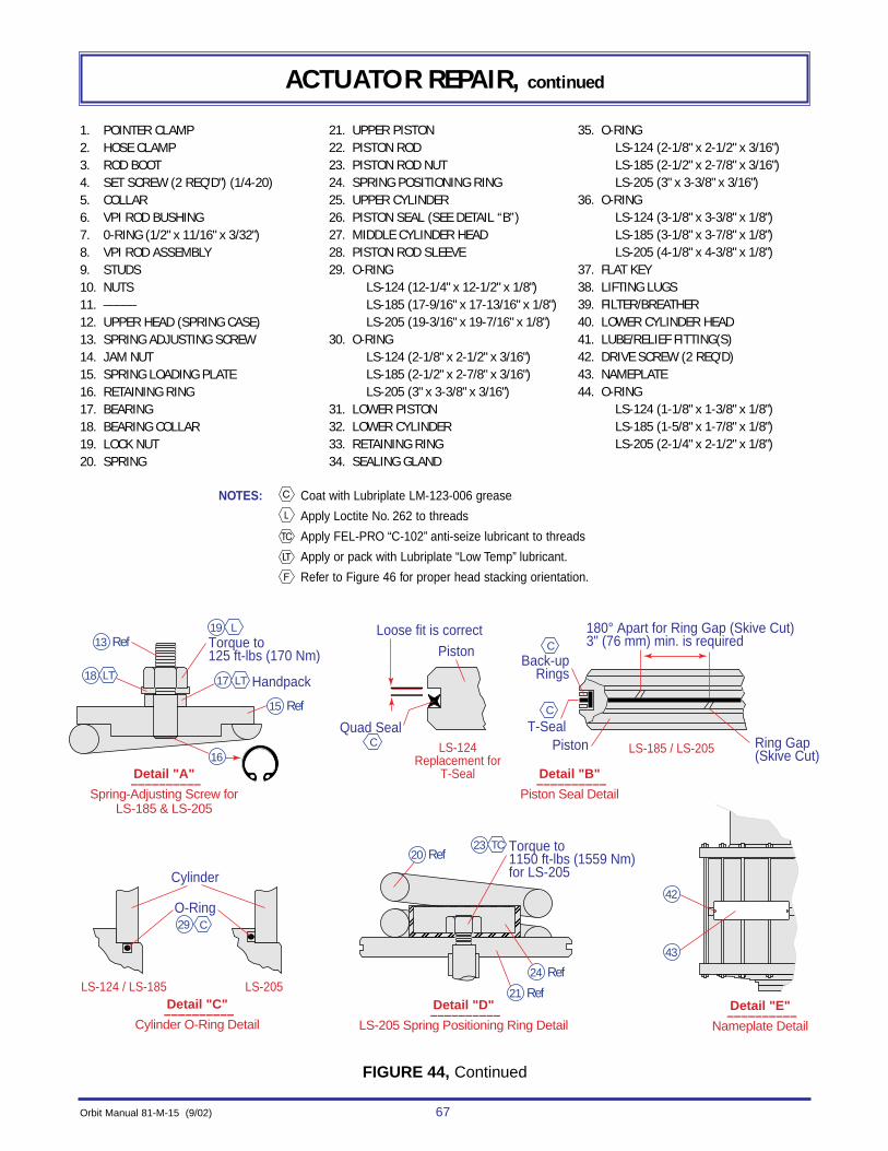
Orbit Manual 81-M-15 (9/02) 67
ACTUATOR REPAIR, continued
1. POINTER CLAMP2. HOSE CLAMP3. ROD BOOT4. SET SCREW (2 REQ’D") (1/4-20)5. COLLAR6. VPI ROD BUSHING7. 0-RING (1/2" x 11/16" x 3/32")8. VPI ROD ASSEMBLY9. STUDS10. NUTS11. –––––12. UPPER HEAD (SPRING CASE)13. SPRING ADJUSTING SCREW14. JAM NUT15. SPRING LOADING PLATE16. RETAINING RING17. BEARING18. BEARING COLLAR19. LOCK NUT20. SPRING
21. UPPER PISTON22. PISTON ROD23. PISTON ROD NUT24. SPRING POSITIONING RING25. UPPER CYLINDER26. PISTON SEAL (SEE DETAIL “B”)27. MIDDLE CYLINDER HEAD28. PISTON ROD SLEEVE29. O-RING
LS-124 (12-1/4" x 12-1/2" x 1/8")LS-185 (17-9/16" x 17-13/16" x 1/8")LS-205 (19-3/16" x 19-7/16" x 1/8")
30. O-RINGLS-124 (2-1/8" x 2-1/2" x 3/16")LS-185 (2-1/2" x 2-7/8" x 3/16")LS-205 (3" x 3-3/8" x 3/16")
31. LOWER PISTON32. LOWER CYLINDER33. RETAINING RING34. SEALING GLAND
35. O-RINGLS-124 (2-1/8" x 2-1/2" x 3/16")LS-185 (2-1/2" x 2-7/8" x 3/16")LS-205 (3" x 3-3/8" x 3/16")
36. O-RINGLS-124 (3-1/8" x 3-3/8" x 1/8")LS-185 (3-1/8" x 3-7/8" x 1/8")LS-205 (4-1/8" x 4-3/8" x 1/8")
37. FLAT KEY38. LIFTING LUGS39. FILTER/BREATHER40. LOWER CYLINDER HEAD41. LUBE/RELIEF FITTING(S)42. DRIVE SCREW (2 REQ’D)43. NAMEPLATE44. O-RING
LS-124 (1-1/8" x 1-3/8" x 1/8")LS-185 (1-5/8" x 1-7/8" x 1/8")LS-205 (2-1/4" x 2-1/2" x 1/8")
NOTES: Coat with Lubriplate LM-123-006 grease
Apply Loctite No. 262 to threads
Apply FEL-PRO “C-102” anti-seize lubricant to threads
Apply or pack with Lubriplate “Low Temp” lubricant.
Refer to Figure 46 for proper head stacking orientation.
���
���
���
����
Detail "D" ––––––––––
LS-205 Spring Positioning Ring Detail
Detail "B" ––––––––––
Piston Seal Detail
Detail "E" ––––––––––
Nameplate Detail
Cylinder
Piston
PistonT-Seal
Back-upRings
O-RingC
C
C
C
LS-185 / LS-205
Loose fit is correct 180° Apart for Ring Gap (Skive Cut)3" (76 mm) min. is required
Quad Seal
Torque to 1150 ft-lbs (1559 Nm)for LS-205
LS-124Replacement for
T-Seal
20 Ref
24 Ref
21 Ref
15 Ref
13 Ref
16
29
Detail "C" ––––––––––
Cylinder O-Ring Detail
LS-124 / LS-185 LS-205
Detail "A" ––––––––––
Spring-Adjusting Screw forLS-185 & LS-205
TC23
Handpack
Torque to125 ft-lbs (170 Nm)
LT17LT18
L19
42
43
Ring Gap(Skive Cut)
FIGURE 44, Continued

68 Orbit Manual 81-M-15 (9/02)
ACTUATOR REPAIR, continued
ASSEMBLY OF SPRING-CLOSE ACTUATOR (LS-124/185/205)
Refer to Figure 44 for assembly of the actuator. (Lubricate at the points noted in the figureduring assembly.)
1. If removed, attach the nameplate (Item 43) with two (2) drive screws (Item 42).(See detail “E”.)
2. Install the lube/relief fittings (Item 41) if they were removed or missing. SeeFigure 45 below for exact arrangement of fittings. (Note: Failure to install thelube and relief fittings in the proper hole could cause the valve/ actuator tolock-up.)
Lube Fitting
Relief Fitting (Button head type)used ONLY on LS-124 and LS-185-D-4/14actuators manufacturedafter December 1982.
For Actuators:LS-124-D-2/3/4/12/13/14
LS-185-D-4/5/14/15LS-205-D-5/6/15/16
Lube Fitting
Relief Fitting (Button head type)
For Actuators:LS-124-D-20/21/23/25/26/27
LS-185-D-20/25/26
Lube Fitting
Lube Fitting
For Actuators:LS-124-D-22/24
3. If removed, install the lifting lugs and the filter/breather (Items 38 & 39).
4. Securely bolt or clamp the lower cylinder head (Item 40) to a clean workbench. This will be necessary later in the assembly, to restrain the actuatorwhile tightening the highly torqued piston rod nut (Item 23).
5. Install the flat key (Item 37) into the piston rod (Item 22). Slide the piston rodand flat key into the lower cylinder head (Item 40).
6. Install the inner and outer O-rings (Items 35 & 36) on the sealing gland (Item34). Slip the sealing gland with O-rings over the piston rod (Item 22) and intothe recess in the lower cylinder head (Item 40). (Note: It may be necessary totap it into place using a soft face hammer and block of wood.) Install the retain-ing ring (Item 33) in the ring groove in the lower cylinder head. (Note: checkthat the ring fully seats into the ring groove.)
7. Screw alignment tool Z-2886 hand tight into the threaded hole in the lower pis-ton (Item 31). Install the piston seal (Item 26 - see detail “B”) on the lower pis-ton. Install the piston so that the alignment tool drops through the hole for theVPI rod bushing (Item 6). (Note: Two tapped holes are provided in the top ofthe piston, for lifting.)
8. Install the lower cylinder head O-ring (Item 29 - see detail “C” ) on the lowercylinder head (Item 40). Install the lower cylinder (Item 32). (Note: Match upthe alignment marks “ ” on the cylinder and the lower cylinder head if theywere marked at disassembly. Be careful not to damage the inside surface ofthe lower cylinder.)
FIGURE 45Lube / Relief Fitting Arrangement
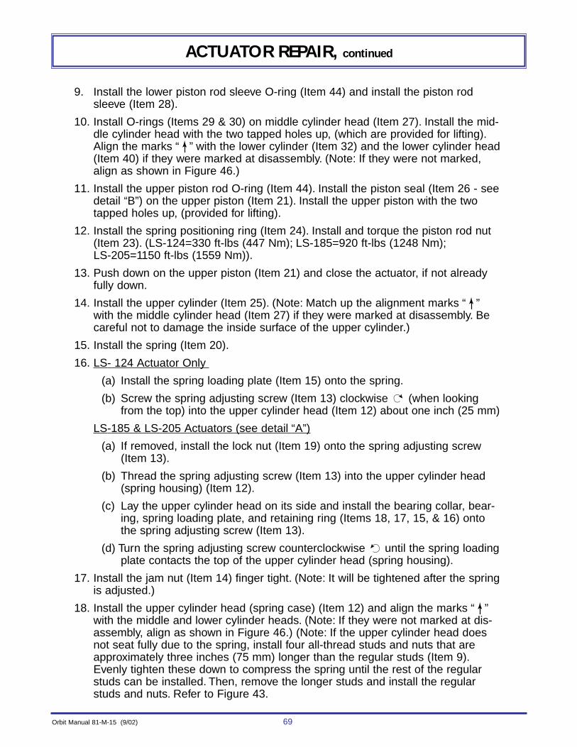
Orbit Manual 81-M-15 (9/02) 69
ACTUATOR REPAIR, continued
9. Install the lower piston rod sleeve O-ring (Item 44) and install the piston rodsleeve (Item 28).
10. Install O-rings (Items 29 & 30) on middle cylinder head (Item 27). Install the mid-dle cylinder head with the two tapped holes up, (which are provided for lifting).Align the marks “ ” with the lower cylinder (Item 32) and the lower cylinder head(Item 40) if they were marked at disassembly. (Note: If they were not marked,align as shown in Figure 46.)
11. Install the upper piston rod O-ring (Item 44). Install the piston seal (Item 26 - seedetail “B”) on the upper piston (Item 21). Install the upper piston with the twotapped holes up, (provided for lifting).
12. Install the spring positioning ring (Item 24). Install and torque the piston rod nut(Item 23). (LS-124=330 ft-lbs (447 Nm); LS-185=920 ft-lbs (1248 Nm);LS-205=1150 ft-lbs (1559 Nm)).
13. Push down on the upper piston (Item 21) and close the actuator, if not alreadyfully down.
14. Install the upper cylinder (Item 25). (Note: Match up the alignment marks “ ”with the middle cylinder head (Item 27) if they were marked at disassembly. Becareful not to damage the inside surface of the upper cylinder.)
15. Install the spring (Item 20).
16. LS- 124 Actuator Only
(a) Install the spring loading plate (Item 15) onto the spring.
(b) Screw the spring adjusting screw (Item 13) clockwise (when lookingfrom the top) into the upper cylinder head (Item 12) about one inch (25 mm)
LS-185 & LS-205 Actuators (see detail “A”)
(a) If removed, install the lock nut (Item 19) onto the spring adjusting screw(Item 13).
(b) Thread the spring adjusting screw (Item 13) into the upper cylinder head(spring housing) (Item 12).
(c) Lay the upper cylinder head on its side and install the bearing collar, bear-ing, spring loading plate, and retaining ring (Items 18, 17, 15, & 16) ontothe spring adjusting screw (Item 13).
(d) Turn the spring adjusting screw counterclockwise until the spring loadingplate contacts the top of the upper cylinder head (spring housing).
17. Install the jam nut (Item 14) finger tight. (Note: It will be tightened after the springis adjusted.)
18. Install the upper cylinder head (spring case) (Item 12) and align the marks “ ”with the middle and lower cylinder heads. (Note: If they were not marked at dis-assembly, align as shown in Figure 46.) (Note: If the upper cylinder head doesnot seat fully due to the spring, install four all-thread studs and nuts that areapproximately three inches (75 mm) longer than the regular studs (Item 9).Evenly tighten these down to compress the spring until the rest of the regularstuds can be installed. Then, remove the longer studs and install the regularstuds and nuts. Refer to Figure 43.

70 Orbit Manual 81-M-15 (9/02)
ACTUATOR REPAIR, continued
���
��
��
��
����
��
����
���
���
��
��
Threaded LifitingLug Holes
Install (2) Longer Studs(15-1/8 (15.12) (384 mm) long)for Gas-Over-Oil Tankin the Holes Shown
3/8 NPT LowerGas (Air) Port
1/2 - 13 UNC ThreadedLifting Holes
UpperCylinder
Head
MiddleCylinder
Head
LowerCylinder
Head
1"-12 UNFVPI Rod
Hole
UpperCylinder
LowerCylinder
Opening Gas(Air) Port
Threaded LifitingLug Holes
Install (2) Longer Studs(19-1/4 (19.25) (489 mm) long)for Gas-Over-Oil Tank in the Holes Shown
3/8 NPT LowerGas (Air) Port
3/4 - 10 UNC ThreadedLifting Holes
UpperCylinder
Head
MiddleCylinder
Head
LowerCylinder
Head
1"-12 UNFVPI Rod
Hole
UpperCylinder
LowerCylinder
Opening Gas(Air) Port
Threaded LifitingLug Holes
Install (2) Longer Studs(21-3/4 (21.75) (552 mm) long)for Gas-Over-Oil Tank inStud Hole Location Shown
1/2 NPT LowerGas (Air) Port
3/4 - 10 UNC ThreadedLifting Holes
UpperCylinder
Head
MiddleCylinder
Head
LowerCylinder
Head
1"-12 UNFVPI Rod
Hole
UpperCylinder
LowerCylinder
Opening Gas(Air) Port
LS-124-D-XS Actuator
––––––––––
LS-185-D-XS Actuator
––––––––––
LS-205-D-XS Actuator
––––––––––
FIGURE 46Cylinder Head Stacking (Alignment)
Orbit Manual 81-M-15 (9/02) 71
ACTUATOR REPAIR, continued
19. Install the studs and nuts (Items 9 & 10) using a criss-cross pattern to tighten.(Note: There are two longer studs and these should be installed as shown inFigure 46 for the gas-over-oil tank.)
20. Remove the alignment tool Z-2886 and install the VPI rod assembly (Item 8)using the slot in the end of the rod to tighten. (Note: Remove all burrs on the rodwith fine emery cloth.)
21. Install the O-ring (Item 7) into the VPI rod bushing (Item 6). Slip the bushing ontothe VPI rod assembly (Item 8) and tighten securely into the lower cylinder head.
22. Slip the hose clamp (Item 2) over one end of the rod boot (Item 3) and the pointerclamp (Item 1) over the other end. Install and tighten the hose clamp and rod bootover the VPI rod bushing (Item 6).
23. Install the collar (Item 5) onto the end of the VPI rod assembly (Item 8) with theset screws (Item 4). Slip the rod boot (Item 3) over the collar so that it is abouteven with the bottom of the collar, and the bottom of the pointer clamp (Item 1) is1/8 (.12) inch (3 mm) from the bottom of the collar. Then tighten the pointerclamp.
24. Install the gas-over-oil tank as described on page 59. The actuator is now readyto mount to a valve. (See page 11 for the various mounting procedures.)

72 Orbit Manual 81-M-15 (9/02)
ACTUATOR REPAIR, continued
DISASSEMBLY OF SPRING-CLOSE ACTUATOR WITH TWO-WAY MECHANISM (LS-124 & LS185)
The following procedure describes a complete disassembly of the actuator. Orbit recom-mends removing the actuator from the valve for any internal repairs. However, some internalrepairs may be done while the actuator is attached to the valve. Extra safety precautions mustbe observed to prevent the spring from unexpectedly expanding, causing personal injury andequipment damage. These precautions are; (to be done in order),
a) Close valve. (Note: The valve may tend to open due to pressure in the valve body asthe spring compression is released or as the actuator is removed.)
b) Be sure the gas (air) pressure to the actuator has been reduced to atmospheric andis maintained there. (Note: It is recommended that the pressure supply line be discon-nected.)
(TYPE-M-) (LS-124 & LS-185) c) Loosen the jam nut and turn the handwheel counterclockwise until it turns freely or
until the dimension shown in Figure 47 below is reached.
(TYPE-N-) (LS-124 & LS-185)c) Remove the lock pin and turn the handwheel counterclockwise until it turns freely
or until the dimension shown in Figure 47 below is reached.d) Refer to Figure 47. Remove four (4) studs and install new, longer all-thread studs and
nuts (3 inches (76 mm) minimum longer than existing studs). Remove the remainingshorter studs. Evenly loosen the nuts on the new longer studs so any remainingspring compression will be released.
CotterHair Pin
HandwheelStem
Stem Boot
Debris Cover
Lock Pin
Non-Adjustable Type NACME Threaded Stem
Spring Close w/Two-Way Manual Mechanism––––––––––––––(except LS-205)
Type M––––––––––––––
Loosen approximately:LS-124 6-1/4" (6.25) (159 mm)LS-185 8" (8.00) (203 mm)
To Relieve Spring Compression
Jam Nut
Additional3" (76 mm)of Threaded Stud
Spring Close
StudNut
Remove (4) Studs and install new longer all thread studs and nuts as shown. Remove other studs; then evenly loosen the nuts on the new longer studs
Turn handwheel counterclockwise until it turns freely to release spring compression
FIGURE 47Removing Spring Case when Actuator is Attached to Valve

Orbit Manual 81-M-15 (9/02) 73
ACTUATOR REPAIR, continued
Refer to Figure 48 for disassembly of the actuator.1. Mark the orientation of the actuator upper, middle &
lower heads and the upper & lower cylinders, usingan arrow “ ”, with something that will not rub off(such as paint, marking pen, etc.). Also, mark theupper & lower cylinders with the words, “Upper” and“Lower”. This will greatly aid in reassembly later. Seeillustration at right.
2. Remove the pointer clamp, hose clamp, and rod boot(Items 1, 2, & 3).
3. Loosen the set screws (Item 4) and remove the collar(Item 5). Remove any burrs on the VPI rod (Item 8)with fine emery cloth. Remove the VPI rod bushing(Item 6), and then the O-ring (Item 7).
4. Securely bolt or clamp the actuator to a clean workbench. (Note: This will be necessary to restrain theactuator while loosening the highly torqued piston rod nut (Item 32) later in the disassembly.)
(Type -M-) (LS-124 & LS-185)5. Remove the cotter pin, handwheel, and the jam nut (Items 9, 10 & 11) (Fig. 48).(TYPE -N-) (LS-124 & LS-185)5. Remove the cotter pin, handwheel, hose clamps, stem boot, and collar (Items 9, 10, 53,
56 and 55) (Fig. 48a).6. Remove the studs and nuts (Items 12 & 13).7. Lift the upper head (spring case) (Item 14) until it clears the upper cylinder (Item 15).Then,
turn the upper head counterclockwise (when viewed from the top) while holding themanual operator stem (Item 16), until the threaded portion of the stem disengages theupper head or stem nut. Do not remove the stem nut (Item 62) or debris cover (Item 59)from upper head. Lift off upper head.
8. Remove, only if damaged, the lifting lugs (Item 17), the folding spring position gage (Item18 - Detail “A”), and the filter/breather (Item 19).
9. LS-124 Actuator Only a. Remove the retaining ring (Item 20) with spanner wrenches.b. Remove the spring (Item 21) and upper cylinder (item 15). (Note: Be careful not to
damage the inside surface of the cylinder.) c. Remove the cap screws (Item 22).d. Lift off the manual operator stem (Item 16) with the bearing housing (Item 23) and
all items attached to it.e. Remove the nut, lower bearing collar, and lower bearing (Items 24, 25 & 26). Then
remove the bearing housing (Item 23) from the stem.f. Remove the hub (Item 27). Then remove the upper bearing and upper collar (Items
28 & 29) from the stem.LS-185 Actuator Only (see Detail “B”)
a. Remove the jam nut, upper bearing collar, and upper bearing (Items 30, 29 & 28).b. Lift off the spring loading plate (Item 31), the spring (Item 21), and the upper cylin-
der (Item 15). (Note: Be careful not to damage the inside surface of the cylinder.) c. Remove the cap screws (Item 22).
UpperHead
Upper
Lower
MiddleHead
LowerHead
Cylinder
Cylinder

74 Orbit Manual 81-M-15 (9/02)
ACTUATOR REPAIR, continued
LS-185 LowerPiston Detail
See Detail "B"for LS-185 actuator
(LS-124 configuration shown)
TORQUE TO:LS-124....330 ft-lbs. (447 Nm)LS-185....920 ft-lbs. (1248 Nm)
LS-124....155 ft-lbs. (210 Nm)LS-185....440 ft-lbs. (597 Nm)
TC17
TC11
1427
21
15
33
42
43
41
45
4915
243
TC20
Torque to:50 ft-lbs (68 Nm)
Z-2886Alignment Tool(Hand Tighten only)
See Figure 49 for exact arrangement
1/8 (.12) (3mm)
TC 6
C
C
C
7
C 35
C 38
44
CL 8
LP29
LT
LT Hand Pack28
LP Hand Pack26
TC Torque to:60 ft-lbs. (81 Nm)
22
TC Torque to:LS-124....25 ft-lbs. (34 Nm)LS-185....60 ft-lbs. (81 Nm)
1312
L Apply Loctite to threethreads only; Torque to:24
LP25
C39
C40
C40
C
LP
C46
C48
C47
F50
TC
C 35
C 38
TC 32 TC 19
C 37
F 36
34
23
16
189
10
C
See Detail "C"
See Detail "C"
FIGURE 48, Type -M-,LS-124/LS-185 Spring Close with Two-Way Mechanism - Disassembly/Assembly
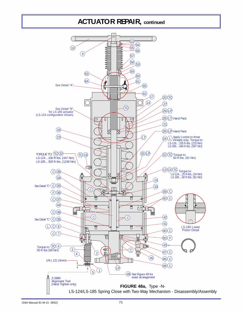
Orbit Manual 81-M-15 (9/02) 75
ACTUATOR REPAIR, continued
LS-185 LowerPiston Detail
See Detail "B"for LS-185 actuator
(LS-124 configuration shown)
See Detail "A"
TORQUE TO:LS-124....330 ft-lbs. (447 Nm)LS-185....920 ft-lbs. (1248 Nm)
LS-124....155 ft-lbs. (210 Nm)LS-185....440 ft-lbs. (597 Nm)
14
53
55
27
21
15
33
42
43
41
45
4915
243
TC20
Torque to:50 ft-lbs (68 Nm)
Z-2886Alignment Tool(Hand Tighten only)
See Figure 49 for exact arrangement
1/8 (.12) (3mm)
TC 6
C
C
C
7
C 35
C 38
44
CL 8
LP29
LT
LT Hand Pack28
LP Hand Pack26
TC Torque to:60 ft-lbs. (81 Nm)
22
TC Torque to:LS-124....25 ft-lbs. (34 Nm)LS-185....60 ft-lbs. (81 Nm)
1312
L Apply Loctite to threethreads only; Torque to:24
LP25
C39
C40
C40
C
LP
C46
C48
C47
F50
TC
C 35
C 38
TC 32 TC 19
C 37
F 36
34
23
16
9
10
C
See Detail "C"
See Detail "C"
17
53
60
61
54
56
65
62
63
64
57
58
59
FIGURE 48a, Type -N-LS-124/LS-185 Spring Close with Two-Way Mechanism - Disassembly/Assembly

76 Orbit Manual 81-M-15 (9/02)
Detail "C" ––––––––––
Piston Seal Detail
Detail "D" ––––––––––
Nameplate Detail
Piston
PistonT-Seal
Back-upRings
C
C
C
LS-185
Spring Position GaugeType M, Figure 48
Loose fit is correct 180° Apart for Ring Gap (Skive Cut)3" (76 mm) min. is required
Quad SealLS-124
Replacement forT-Seal
21 RefRef16
Detail "B" ––––––––––
Spring Loading Plate LS-185 ActuatorDetail "A"
––––––––––Non-Adjustable Type N
w/Acme Threaded Stem, Figure 48-a
Handpack
Indicating Plate
Apply afterinstalling jam nut
(item 30)
Apply Loctite toThree threads only.Torque to125 ft-lbs (170 Nm)
LT28
TC
TC
L30
31
51
52
Ring Gap(Skive Cut)
LT29
Screw (2 req'd.)
Thumb Screw
Pivot Arm
Self TappingScrews
Bracket BaseUpper Head (Spring Case)
CotterHair Pin
(item 63)One thru hole
in Debris CoverLock Pinw/Chain & Ring(item 64, 60, 61)
ACTUATOR REPAIR, continued
1. POINTER CLAMP2. HOSE CLAMP3. ROD B00T4. SET SCREW (2 REQ'D)(1/4-20)5. COLLAR6. VPI ROD BUSHING7. O-RING (1/2 x 11/16 x 3/32)8. VPI ROD ASSY9. COTTER PIN10. HANDWHEEL11. JAM NUT12. STUDS13. NUTS14. UPPER HEAD (SPRING CLOSE)15. UPPER CYLINDER16. MANUAL OPERATOR STEM17. LIFTING LUGS18. SPRING POSITION GAGE19. FILTER/BREATHER20. RETAINING RING21. SPRING22. CAPSCREWS 23. BEARING HOUSING24. NUT25. LOWER BEARING COLLAR
26. LOWER BEARING27. HUB28. UPPER BEARING29. UPPER BEARING COLLAR30. JAM NUT31. SPRING LOADING PLATE32. PISTON ROD NUT33. SPRING POSITIONING RING34. UPPER PISTON35. PISTON SEAL (SEE DETAIL "C" )36. MIDDLE CYLINDER HEAD37. PISTON ROD SLEEVE38. O-RING (2 REQ'D)
LS-124 (1-1/8 x 1-3/8 x 1/8)LS-185 (1-5/8 x 1-7/8 x 1/8)
39. 0-R1NGLS-124 (2-1/8 x 2-1/2 x 3/16)LS-185 (2-1/2 x 2-7/8 x 3/16)
40. O-RING (3 REQ'D)LS-124 (12-1/4 x 12-1/2 x 1/8)LS-185 (17-9/16 x 17-13/16 x 1/8)
41. LOWER PISTON42. LOWER CYLINDER43. RETAINING RING44. PISTON ROD
45. SEALING GLAND46. O-RING (INNER)
LS-124 (2-1/8 x 2-1/2 x 3/16)LS-185 (2-1/2 x 2-7/8 x 3/16)
47. O-RING (OUTER)LS-124 (3-1/8 x 3-3/8 x 1/8)LS-185 (3-5/8 x 3-7/8 x 1/8)
48. KEY49. LUBE RELIEF FITTING(S)50. LOWER CYLINDER HEAD51. DRIVE SCREWS (2 REQ'D)52. NAMEPLATE53. HOSE CLAMP54. O-RING55. COLLAR56. STEM BOOT57. RETAINING RING58. COLLAR59. DEBRIS COVER (DO NOT REMOVE )60. CHAIN-LOCK PIN61. SPLIT RING-LOCK PIN62. STEM NUT (DO NOT REMOVE )63. COTTER HAIR PIN64. LOCK PIN65. LUBE FITTING
NOTES: Coat with Lubriplate LM-123-006 grease
Apply Loctite No. 262 to thread
Apply FEL-PRO “C-102” anti-seize lubricant to threads
Apply or pack with Lubriplate “930-AA” lubricant.
Refer to Figure 50 for proper head stacking orientation.
FIGURE 48, continued

Orbit Manual 81-M-15 (9/02) 77
ACTUATOR REPAIR, continued
d. Lift off the manual operator stem (Item 16) with the bearing housing (Item 23)and all items attached to it.
e. Remove the stem (Item 16) from the bearing housing (Item 23).
f. Remove the nut, lower bearing collar and lower bearing (Item 24, 25 & 26).
10. Remove the piston rod nut (Item 32) and spring positioning ring (Item 33).
11. Remove the upper piston (Item 34). (Note: Two tapped holes are provided for lifting.)Remove the upper piston seal (Item 35 - see Detail “C”).
12. Lift off the middle cylinder head and remove the piston rod sleeve (Items 36 & 37).(Note: If the middle cylinder head and sleeve come off together, separate them afterremoval from the actuator. Two tapped holes in the middle cylinder head are providedfor lifting. The pipe and tubing fittings may remain in place unless damaged.) Removethe O-rings (Items 38, 39 & 40).
13. Remove the lower piston with the VPI rod assembly (Items 41 & 8). Remove the lowercylinder (Item 42). Remove the lower piston seal (Item 35 see detail “C”) and thecylinder O-ring (Item 40). Unscrew the VPI rod from the lower piston.
NOTES:(a) Two tapped holes in the lower piston are provided for lifting.
(b) Be careful not to damage the inside surface of the cylinder.
(c) If the lower piston and the lower cylinder come off together, separatethem after removing from the actuator.
(d) The VPI rod may require heating with a propane torch to 350°F (177°C)for a few minutes to degrade the Loctite on the threads.
14. Remove the retaining ring (Item 43).
15. Pulling quickly upwards on the piston rod (Item 44), pop out the sealing gland (Item45). Slide the sealing gland over the top of the piston rod. Remove the inner andouter O-rings (Items 46 & 47), then remove the key (Item 48).
16. Remove, only if damaged, the lifting lugs and the filter/breather (Items 17 & 19) fromthe upper cylinder head (spring case).
17. Remove, only if damaged, the lube and relief fitting (Item 49) from the lower cylinderhead (Item 50). (Note: Pipe and tubing fittings may remain in the lower cylinder headunless damaged.)
18. Remove two (2) drive screws and nameplate (Items 51 & 52) only if (a) damaged,
(b) replacing middle cylinder head, or
(c) making changes to the nameplate. See detail “D”.19. Clean and inspect parts. (Note: Orbit recommends replacing all O-rings and seals any
time an actuator is disassembled, to prevent future unscheduled repairs because ofan O-ring that appeared good.)

78 Orbit Manual 81-M-15 (9/02)
ACTUATOR REPAIR, continued
ASSEMBLY OF SPRING CLOSE ACTUATOR WITH TWO-WAY MECHANISM(LS-124 and LS-185)
Refer to figures 48 and 48a for assembly of the actuator. (Lubricate at the points noted in thefigure during assembly.)
1. If removed, attach the nameplate (Item 52) with two (2) drive screws (Item 51). (Seedetail “D”.)
2. Install the lube/relief fittings (Item 49) if they were removed or missing. See Figure 49below for exact arrangement of fittings. (Note: Failure to install the lube and relief fit-tings in the proper hole could cause the valve/actuator to lock-up.)
3. If removed, install the lifting lugs and the filter/breather (Items 17 & 19).4. Securely bolt or clamp the lower cylinder head (Item 50) to a clean work bench. This
will be necessary later in the assembly to restrain the actuator while tightening thehighly torqued piston rod nut (Item 32).
5. Install the flat key (Item 48) into the piston rod (Item 44). Slide the piston rod and flatkey into the lower cylinder head (Item 50).
6. Install the inner and outer O-rings (Items 46 & 47) on the sealing gland (Item 45). Slipthe sealing gland with O-rings over the piston rod (Item 44) and into the recess in thelower cylinder head (Item 50). (Note: It may be necessary to tap it into place using asoft face hammer and block of wood.) Install the retaining ring (Item 43) in the ringgroove in the lower cylinder head. (Note: Check carefully that the ring fully seats intothe ring groove.)
7. Screw the alignment tool Z-2886 hand tight into the threaded hole in the lower piston(Item 41). Install the piston seal (Item 35 - see detail “C”) on the lower piston. Installthe piston so that the alignment tool drops through the hole for the VPI rod bushing(Item 6). (Note: Two tapped holes are provided in the top of the piston for lifting.)
8. Install the lower cylinder head O-ring (Item 40) on the lower cylinder head (Item 50).Install the lower cylinder (Item 42). (Note: Match up the alignment marks “ ” on thecylinder and the lower cylinder head if they were marked at disassembly. Be carefulnot to damage the inside surface of the lower cylinder.)
Lube Fitting
Relief Fitting (Button head type)used on all LS-124 actuatorsand LS-185-D-4/14actuators manufacturedafter December 1982.
For Actuators:LS-124-D-2/3/4/12/13/14
LS-185-D-4/5/14/15
Lube Fitting
Relief Fitting (Button head type)
For Actuators:LS-124-D-20/21/23/25/26/27
LS-185-D-20/25/26
Lube Fitting
Lube Fitting
For Actuators:LS-124-D-22/24
FIGURE 49Lube/Relief Fitting Arrangement
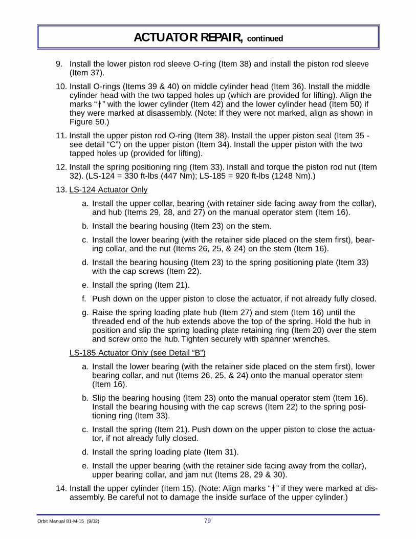
Orbit Manual 81-M-15 (9/02) 79
ACTUATOR REPAIR, continued
9. Install the lower piston rod sleeve O-ring (Item 38) and install the piston rod sleeve(Item 37).
10. Install O-rings (Items 39 & 40) on middle cylinder head (Item 36). Install the middlecylinder head with the two tapped holes up (which are provided for lifting). Align themarks “ ” with the lower cylinder (Item 42) and the lower cylinder head (Item 50) ifthey were marked at disassembly. (Note: If they were not marked, align as shown inFigure 50.)
11. Install the upper piston rod O-ring (Item 38). Install the upper piston seal (Item 35 -see detail “C”) on the upper piston (Item 34). Install the upper piston with the twotapped holes up (provided for lifting).
12. Install the spring positioning ring (Item 33). Install and torque the piston rod nut (Item32). (LS-124 = 330 ft-lbs (447 Nm); LS-185 = 920 ft-lbs (1248 Nm).)
13. LS-124 Actuator Only
a. Install the upper collar, bearing (with retainer side facing away from the collar),and hub (Items 29, 28, and 27) on the manual operator stem (Item 16).
b. Install the bearing housing (Item 23) on the stem.
c. Install the lower bearing (with the retainer side placed on the stem first), bear-ing collar, and the nut (Items 26, 25, & 24) on the stem (Item 16).
d. Install the bearing housing (Item 23) to the spring positioning plate (Item 33)with the cap screws (Item 22).
e. Install the spring (Item 21).
f. Push down on the upper piston to close the actuator, if not already fully closed.
g. Raise the spring loading plate hub (Item 27) and stem (Item 16) until thethreaded end of the hub extends above the top of the spring. Hold the hub inposition and slip the spring loading plate retaining ring (Item 20) over the stemand screw onto the hub. Tighten securely with spanner wrenches.
LS-185 Actuator Only (see Detail “B”)
a. Install the lower bearing (with the retainer side placed on the stem first), lowerbearing collar, and nut (Items 26, 25, & 24) onto the manual operator stem(Item 16).
b. Slip the bearing housing (Item 23) onto the manual operator stem (Item 16).Install the bearing housing with the cap screws (Item 22) to the spring posi-tioning ring (Item 33).
c. Install the spring (Item 21). Push down on the upper piston to close the actua-tor, if not already fully closed.
d. Install the spring loading plate (Item 31).
e. Install the upper bearing (with the retainer side facing away from the collar),upper bearing collar, and jam nut (Items 28, 29 & 30).
14. Install the upper cylinder (Item 15). (Note: Align marks “ ” if they were marked at dis-assembly. Be careful not to damage the inside surface of the upper cylinder.)
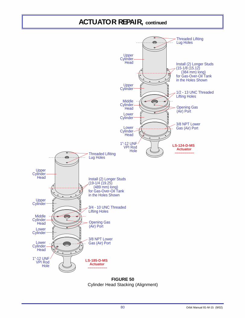
80 Orbit Manual 81-M-15 (9/02)
ACTUATOR REPAIR, continued
���
���
��
���
���
�
��
���
Threaded LifitingLug Holes
Install (2) Longer Studs(15-1/8 (15.12) (384 mm) long)for Gas-Over-Oil Tankin the Holes Shown
3/8 NPT LowerGas (Air) Port
1/2 - 13 UNC ThreadedLifting Holes
UpperCylinder
Head
MiddleCylinder
Head
LowerCylinder
Head
1"-12 UNFVPI Rod
Hole
UpperCylinder
LowerCylinder
Opening Gas(Air) Port
Threaded LifitingLug Holes
Install (2) Longer Studs(19-1/4 (19.25) (489 mm) long)for Gas-Over-Oil Tank in the Holes Shown
3/8 NPT LowerGas (Air) Port
3/4 - 10 UNC ThreadedLifting Holes
UpperCylinder
Head
MiddleCylinder
Head
LowerCylinder
Head
1"-12 UNFVPI Rod
Hole
UpperCylinder
LowerCylinder
Opening Gas(Air) Port
LS-124-D-MS Actuator
––––––––––
LS-185-D-MS Actuator
––––––––––
FIGURE 50Cylinder Head Stacking (Alignment)
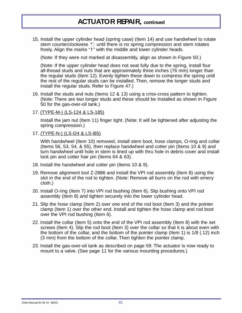
Orbit Manual 81-M-15 (9/02) 81
ACTUATOR REPAIR, continued
15. Install the upper cylinder head (spring case) (Item 14) and use handwheel to rotatestem counterclockwise until there is no spring compression and stem rotatesfreely. Align the marks “ ” with the middle and lower cylinder heads.
(Note: If they were not marked at disassembly, align as shown in Figure 50.)
(Note: If the upper cylinder head does not seat fully due to the spring, install fourall-thread studs and nuts that are approximately three inches (76 mm) longer thanthe regular studs (Item 12). Evenly tighten these down to compress the spring untilthe rest of the regular studs can be installed. Then, remove the longer studs andinstall the regular studs. Refer to Figure 47.)
16. Install the studs and nuts (Items 12 & 13) using a criss-cross pattern to tighten.(Note: There are two longer studs and these should be Installed as shown in Figure50 for the gas-over-oil tank.)
17. (TYPE-M-) (LS-124 & LS-185)
Install the jam nut (Item 11) finger tight. (Note: It will be tightened after adjusting thespring compression.)
17. (TYPE-N-) (LS-l24 & LS-l85)
With handwheel (Item 10) removed, install stem boot, hose clamps, O-ring and collar(Items 56, 53, 54, & 55), then replace handwheel and cotter pin (Items 10 & 9) andturn handwheel until hole in stem is lined up with thru hole in debris cover and installlock pin and cotter hair pin (Items 64 & 63).
18. Install the handwheel and cotter pin (Items 10 & 9).
19. Remove alignment tool Z-2886 and install the VPI rod assembly (Item 8) using theslot in the end of the rod to tighten. (Note: Remove all burrs on the rod with emerycloth.)
20. Install O-ring (Item 7) into VPI rod bushing (Item 6). Slip bushing onto VPI rodassembly (Item 8) and tighten securely into the lower cylinder head.
21. Slip the hose clamp (Item 2) over one end of the rod boot (Item 3) and the pointerclamp (Item 1) over the other end. Install and tighten the hose clamp and rod bootover the VPI rod bushing (Item 6).
22. Install the collar (Item 5) onto the end of the VPI rod assembly (Item 8) with the setscrews (Item 4). Slip the rod boot (Item 3) over the collar so that it is about even withthe bottom of the collar, and the bottom of the pointer clamp (Item 1) is 1/8 (.12) inch(3 mm) from the bottom of the collar. Then tighten the pointer clamp.
23. Install the gas-over-oil tank as described on page 59. The actuator is now ready tomount to a valve. (See page 11 for the various mounting procedures.)
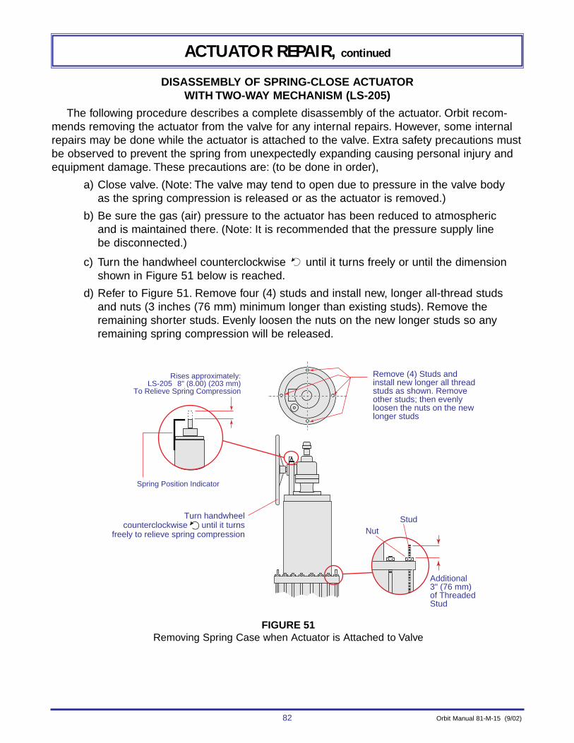
82 Orbit Manual 81-M-15 (9/02)
ACTUATOR REPAIR, continued
DISASSEMBLY OF SPRING-CLOSE ACTUATOR WITH TWO-WAY MECHANISM (LS-205)
The following procedure describes a complete disassembly of the actuator. Orbit recom-mends removing the actuator from the valve for any internal repairs. However, some internalrepairs may be done while the actuator is attached to the valve. Extra safety precautions mustbe observed to prevent the spring from unexpectedly expanding causing personal injury andequipment damage. These precautions are: (to be done in order),
a) Close valve. (Note: The valve may tend to open due to pressure in the valve bodyas the spring compression is released or as the actuator is removed.)
b) Be sure the gas (air) pressure to the actuator has been reduced to atmosphericand is maintained there. (Note: It is recommended that the pressure supply linebe disconnected.)
c) Turn the handwheel counterclockwise until it turns freely or until the dimensionshown in Figure 51 below is reached.
d) Refer to Figure 51. Remove four (4) studs and install new, longer all-thread studsand nuts (3 inches (76 mm) minimum longer than existing studs). Remove theremaining shorter studs. Evenly loosen the nuts on the new longer studs so anyremaining spring compression will be released.
Additional3" (76 mm)of Threaded Stud
StudNut
Remove (4) Studs and install new longer all thread studs as shown. Remove other studs; then evenly loosen the nuts on the new longer studs
Spring Position Indicator
Rises approximately:LS-205 8" (8.00) (203 mm)
To Relieve Spring Compression
Turn handwheelcounterclockwise until it turns
freely to relieve spring compression
FIGURE 51Removing Spring Case when Actuator is Attached to Valve
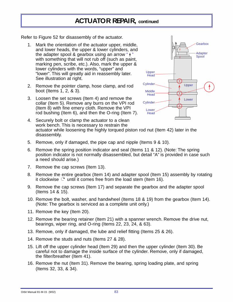
Orbit Manual 81-M-15 (9/02) 83
ACTUATOR REPAIR, continued
Refer to Figure 52 for disassembly of the actuator.
1. Mark the orientation of the actuator upper, middle,and lower heads, the upper & lower cylinders, andthe adapter spool & gearbox using an arrow “ ”with something that will not rub off (such as paint,marking pen, scribe, etc.). Also, mark the upper &lower cylinders with the words, “upper” and“lower”. This will greatly aid in reassembly later.See illustration at right.
2. Remove the pointer clamp, hose clamp, and rodboot (Items 1, 2, & 3).
3. Loosen the set screws (Item 4) and remove thecollar (Item 5). Remove any burrs on the VPI rod(Item 8) with fine emery cloth. Remove the VPIrod bushing (Item 6), and then the O-ring (Item 7).
4. Securely bolt or clamp the actuator to a cleanwork bench. This is necessary to restrain theactuator while loosening the highly torqued piston rod nut (Item 42) later in the disassembly.
5. Remove, only if damaged, the pipe cap and nipple (Items 9 & 10).
6. Remove the spring position indicator and seal (Items 11 & 12). (Note: The spring position indicator is not normally disassembled, but detail “A” is provided in case sucha need should arise.)
7. Remove the cap screws (Item 13).
8. Remove the entire gearbox (Item 14) and adapter spool (Item 15) assembly by rotatingit clockwise until it comes free from the load stem (Item 16).
9. Remove the cap screws (Item 17) and separate the gearbox and the adapter spool(Items 14 & 15).
10. Remove the bolt, washer, and handwheel (Items 18 & 19) from the gearbox (Item 14).(Note: The gearbox is serviced as a complete unit only.)
11. Remove the key (Item 20).
12. Remove the bearing retainer (Item 21) with a spanner wrench. Remove the drive nut,bearings, wiper ring, and O-ring (Items 22, 23, 24, & 63).
13. Remove, only if damaged, the lube and relief fitting (Items 25 & 26).
14. Remove the studs and nuts (Items 27 & 28).
15. Lift off the upper cylinder head (Item 29) and then the upper cylinder (Item 30). Becareful not to damage the inside surface of the cylinder. Remove, only if damaged, the filter/breather (Item 41).
16. Remove the nut (Item 31). Remove the bearing, spring loading plate, and spring(Items 32, 33, & 34).
UpperHead
Gearbox
AdapterSpool
Upper
Lower
MiddleHead
LowerHead
Cylinder
Cylinder
84 Orbit Manual 81-M-15 (9/02)
ACTUATOR REPAIR, continued
17. Remove the retainer and stem guide (Items 35 & 36).
18. Remove cap screws (Item 37) and lift off the puller housing and load stem (Items 38& 16) together.
19. Allow the load stem (Item 16) to drop thru the puller housing (Item 38). The nut andload stem collar (Items 39 & 40) are to remain attached to the load stem.
20. Remove the piston rod nut (Item 42) and the attachment plate (Item 43).
21. Remove the upper piston (Item 44). (Note: Two tapped holes are provided for lifting.)Remove the upper piston seal (Item 45 - see detail “C”).
22. Lift off the middle cylinder head and remove the piston rod sleeve (Items 46 & 47).(Note: If the middle cylinder head and sleeve come off together, separate them afterremoval from the actuator. Two tapped holes in the middle cylinder head are provid-ed for lifting. The pipe and tubing fittings may remain in place unless damaged.)Remove the O-rings (Items 48, 49 & 50).
23. Remove the lower piston with the VPI rod assembly (Items 51 & 8). Remove thelower cylinder (Item 52). Remove the lower piston seal (Item 45 see detail “C”) andthe cylinder O-ring (Item 48). Unscrew the VPI rod from the lower piston.NOTES:
(a) Two tapped holes in the lower piston are provided for lifting.
(b) Be careful not to damage the inside surface of the cylinder.
(c) If the lower piston and the lower cylinder come off together, separate themafter removing from the actuator.
(d) The VPI rod may require heating with a propane torch to 350°F (177°C) for afew minutes to degrade the Loctite on the threads.
24. Remove the retaining ring (Item 53).
25. Pulling quickly upwards on the piston rod (Item 54), pop out the sealing gland (Item55). Slide the sealing gland over the top of the piston rod. Remove the inner andouter O-rings (Items 56 & 57), then remove the key (Item 58).
26. Remove, only if damaged, the lube fitting (Item 59) from the lower cylinder head(Item 60). (Note: Pipe and tubing fittings may remain in the lower cylinder headunless damaged.)
27. Remove two (2) drive screws and nameplate (Items 61 & 62) only if
(a) damaged,
(b) replacing middle cylinder head, or
(c) making changes to the nameplate. See detail “D”.
28. Clean and inspect parts. (Note: Orbit recommends replacing all O-rings and sealsany time an actuator is disassembled to prevent future unscheduled repairs becauseof an O-ring that appeared good.)

Orbit Manual 81-M-15 (9/02) 85
ACTUATOR REPAIR, continued
TORQUE TO:1150 ft-lbs. (1559 Nm)
TORQUE TO:60 ft-lbs. (81 Nm)
TORQUE TO:100 ft-lbs. (136 Nm)
TORQUE TO:60 ft-lbs. (81 Nm)
TORQUE TO:150 ft-lbs. (203 Nm)
TORQUE TO:120 ft-lbs. (163 Nm)
TC10
C63
TC17
C24TC21
L31
L39
F29
TC28
C50
C48
M32
M40
53
Z-2886Alignment Tool(Hand Tighten only)
1/8 (.12) (3mm)
C 45C 49
Apply Loctite to top three (3) threads only
Hand pack & install with stamped name & number toward loading plate
Tighten Securely
F60
LP
C57
See Detail "C"
SeeDetail "C"
SeeDetail "C"
C56
C
C C
C58
55
591
24
3
54
5
M
Torque to:50 ft-lbs (68 Nm) TC 6
C 7
CL 8
F 46
C 45
43
38
36
19
47
C 49
TC 37
TC 42
M
M
C
TC
35
C 12
M 23
M 23
TC 13
TC 18
11
26
15
9
22
20
25
33
34
16
27
44
52
51
30
14
TC 41
1/16" (1.6 mm)
C
Hand Pack
See Detail "A"
See Detail "B"
Gear Box is serviced asa complete unit only
Hand Pack
FIGURE 52LS-205 Spring-Close with Two-Way Mechanism - Disassembly/Assembly
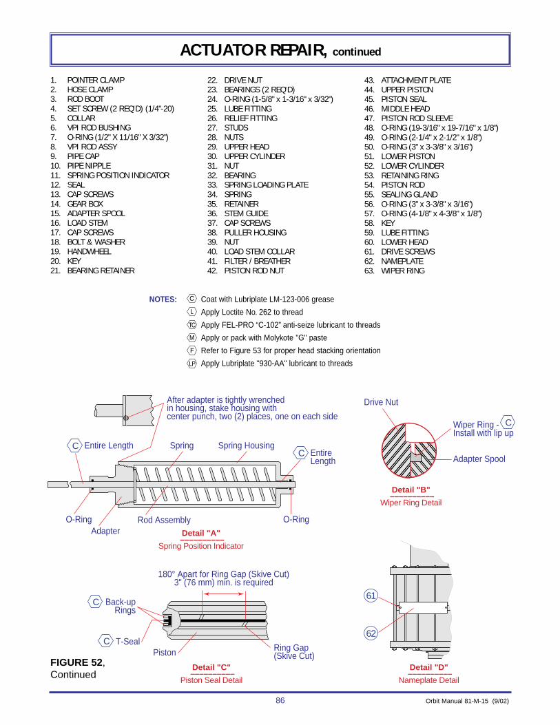
86 Orbit Manual 81-M-15 (9/02)
ACTUATOR REPAIR, continued
����
�
�
���
Detail "C" ––––––––––
Piston Seal Detail
Detail "D" ––––––––––
Nameplate Detail
PistonT-Seal
Adapter Spool
Drive Nut
Wiper Ring - Install with lip up
Back-upRings
Entire Length
O-Ring O-RingAdapter
Rod Assembly
Spring Spring Housing
��
�� ����
C
CEntire Length
C
C
C
61
62
180° Apart for Ring Gap (Skive Cut)3" (76 mm) min. is required
After adapter is tightly wrenchedin housing, stake housing withcenter punch, two (2) places, one on each side
Detail "B" ––––––––––
Wiper Ring Detail
Detail "A" ––––––––––
Spring Position Indicator
Ring Gap(Skive Cut)
1. POINTER CLAMP2. HOSE CLAMP3. ROD BOOT4. SET SCREW (2 REQ'D) (1/4"-20)5. COLLAR6. VPI ROD BUSHING7. O-RING (1/2" X 11/16" X 3/32")8. VPI ROD ASSY9. PIPE CAP10. PIPE NIPPLE11. SPRING POSITION INDICATOR12. SEAL13. CAP SCREWS14. GEAR BOX15. ADAPTER SPOOL16. LOAD STEM17. CAP SCREWS18. BOLT & WASHER19. HANDWHEEL20. KEY21. BEARING RETAINER
22. DRIVE NUT23. BEARINGS (2 REQ'D)24. O-RING (1-5/8" x 1-3/16" x 3/32")25. LUBE FITTING26. RELIEF FITTING27. STUDS28. NUTS29. UPPER HEAD30. UPPER CYLINDER31. NUT32. BEARING33. SPRING LOADING PLATE34. SPRING35. RETAINER36. STEM GUIDE37. CAP SCREWS38. PULLER HOUSING39. NUT40. LOAD STEM COLLAR41. FILTER / BREATHER42. PISTON ROD NUT
43. ATTACHMENT PLATE44. UPPER PISTON45. PISTON SEAL46. MIDDLE HEAD47. PISTON ROD SLEEVE48. O-RING (19-3/16" x 19-7/16" x 1/8")49. O-RING (2-1/4" x 2-1/2" x 1/8")50. O-RING (3" x 3-3/8" x 3/16")51. LOWER PISTON52. LOWER CYLINDER53. RETAINING RING54. PISTON ROD55. SEALING GLAND56. O-RING (3" x 3-3/8" x 3/16")57. O-RING (4-1/8" x 4-3/8" x 1/8")58. KEY59. LUBE FITTING60. LOWER HEAD61. DRIVE SCREWS62. NAMEPLATE63. WIPER RING
NOTES: Coat with Lubriplate LM-123-006 grease
Apply Loctite No. 262 to thread
Apply FEL-PRO “C-102” anti-seize lubricant to threads
Apply or pack with Molykote "G" paste
Refer to Figure 53 for proper head stacking orientation
Apply Lubriplate "930-AA" lubricant to threads
FIGURE 52, Continued

Orbit Manual 81-M-15 (9/02) 87
ACTUATOR REPAIR, continued
ASSEMBLY OF SPRING-CLOSE ACTUATOR WITH TWO-WAY MECHANISM (LS-205)Refer to Figure 52 for assembly of the actuator (lubricate at the points noted in the figure, dur-ing assembly.)
1. If removed, attach the nameplate (Item 62) with two (2) drive screws (Item 61). (Seedetail “D”.)
2. If removed, install the lube fitting (Item 59).
3. Securely bolt or clamp the lower cylinder head (Item 60) to a clean work bench. Thiswill be necessary later in the assembly to restrain the actuator while tightening thehighly torqued piston rod nut (Item 42).
4. Install the flat key (Item 58) into the piston rod (Item 54). Slide the piston rod and flatkey into the lower cylinder head (Item 60).
5. Install the inner and outer O-rings (Items 56 & 57) on the sealing gland (Item 55).Slip the sealing gland with O-rings over the piston rod (Item 54) and into the recessin the lower cylinder head (Item 60). (Note: It may be necessary to tap it into placeusing a soft faced hammer and a block of wood.) Install the retaining ring (Item 53)in the ring groove in the lower cylinder head. (Note: Check carefully that the ring fullyseats into the ring groove.)
6. Screw the alignment tool Z-2886 hand tight into the threaded hole in the lower pis-ton (Item 51). Install the piston seal (Item 45 - see detail “C”) on the lower piston.Install piston so that the alignment tool drops through the hole for the VPI rod bush-ing (Item 6). (Note: Two tapped holes are provided in the top of the piston for lifting.)
7. Install the lower cylinder head O-ring (Item 48) on the lower cylinder head (Item 60).Install the lower cylinder (Item 52). Be careful not to damage the inside surface ofthe cylinder. (Note: Match up the alignment marks “ ” on the cylinder and lowercylinder head if they were marked at disassembly.)
8. Install the lower piston rod sleeve O-ring (Item 49) and install the piston rod sleeve(Item 54).
9. Install O-rings (Items 50 & 48) on middle cylinder head (Item 46). Install the middlecylinder head with the two tapped holes on the top (which are provided for lifting).Align the marks “ ” with the lower cylinder (Item 52) and the lower cylinder head(Item 60) if they were marked at disassembly. (Note: If they were not marked, alignas shown in Figure 51. )
10. Install the upper piston rod O-ring (Item 49). Install the piston seal (Item 45 - seedetail “C”) on the upper piston (Item 44). Install the upper piston with the two tappedholes on the top (which are provided for lifting.)
11. Install the attachment plate (Item 43). Install and torque the piston rod nut (Item 42).Torque = 1150 ft-lbs (1559 Nm).
12. If removed, or when installing a new load stem (Item 16), install the load stem collarand nut (Items 40 & 39). Remove any burrs on the load stem, caused by tighteningthe nut, with a small file and fine emery cloth. Be sure to use Loctite on the nut.

88 Orbit Manual 81-M-15 (9/02)
ACTUATOR REPAIR, continued
���
��
���
�� 1/2 NPT Lower
Gas (Air) Port
Align Opening Gas (Air)Port half-way between the1st & 2nd stud holeclockwise from the centerline ( )
Install (2) longer studs(21 - 3/4" (21.75) (552 mm) long)for Gas-Over-Oil tank in studhole location shown
Welded Lifting Lugs
Spring Position Indicator HousingHole (1" - 12 UNF)
Gearbox (be sure the relationshipbetween the gearbox & spring positionindicator housing hole is as shown)
Upper Cylinder Head
CL
Upper Cylinder
Middle Cylinder Head
LS-205-D-M-S Actuator
––––––––––
CL
CLLower Cylinder Head
1" - 12 UNF VPI Rod Hole
3/4" - 10 UNC ThreadedLifting Holes
Lower Cylinder
FIGURE 53Cylinder Head Stacking (Alignment)

Orbit Manual 81-M-15 (9/02) 89
ACTUATOR REPAIR, continued
13. Install the puller housing (Item 38) on the load stem (Item 16). Attach the pullerhousing to the attachment plate (Item 43) with the cap screws (Item 37).
14. Install the stem guide (Item 36) in the groove on the load stem (Item 16). Seat firmlyand then back off 1/2 turn. Install the retainer (Item 35).
15. Push down on the upper piston (Item 44) to close the actuator, if not already fullyclosed. Install spring (Item 34).
16. Lift the load stem (Item 16). Install the spring loading plate, bearing and nut (Items33, 32 & 31). (Note: Be sure to hand pack the bearing and install with stampedname and number toward loading plate.) Tighten nut until 1/16 inch (1.6 mm) threadis exposed at top.
17. Install the upper cylinder (Item 30). (Note: Align marks “ ” if they were marked atdisassembly.)
18. Install the upper cylinder head (spring case) (Item 29) and align the marks “ ” withthe middle and lower cylinder heads. (Note: If they were not marked at disassembly,align as shown in Figure 53.) (Note: If the cylinder head does not seat fully due tothe spring, install four all-thread studs and nuts that are approximately three inches(76 mm) longer than the regular studs (Item 27). Evenly tighten these down to com-press the spring until the rest of the regular studs can be installed. Then remove thelonger studs and install the regular studs. Refer to Figure 51.)
19. Install the studs and nuts (Items 27 & 28) using a criss-cross pattern to tighten.(Note: There are two longer studs and these should be installed as shown in Figure53 for the gas-over-oil tank.)
20. Install, if removed, the lube and relief fittings (Items 25 & 26) into the adapter spool(Item 15).
21. Install the O-ring (Item 24) onto the drive nut (item 22). Install the wiper ring (Item63 - detail “B”) into the adapter spool (Item 15). Install into the adapter spool thebearings, drive nut, and bearing retainer (Items 23, 22, & 21). (Note: Be sure tohand pack the bearings and to properly install the wiper ring as shown in detail “B”).
22. Install the key (Item 20) into the drive nut (Item 22) on the adapter spool assembly.Install the gear box (Item 14) onto the adapter spool assembly using the cap screws(Item 17). (Note: Align marks “ ” if they were made at disassembly.) Install thehandwheel, washer, and bolt (Items 19 & 18).
23. Install the gearbox and adapter spool assembly onto the actuator by rotating itcounterclockwise on the load stem (Item 16). Align the marks “ ”. (Note: If nomarks were made at disassembly, align as in Figure 53.)
24. Install, if removed, the pipe cap and nipple (Items 9 & 10).
25. Install the spring position indicator (Item 11 - detail “A”) using a new seal (Item 12).
90 Orbit Manual 81-M-15 (9/02)
ACTUATOR REPAIR, continued
26. Remove alignment tool Z-2886 and install the VPI rod assembly (Item 8) usingthe slot in the end of the rod to tighten. (Note: Remove all burrs on the rod withemery cloth.)
27. Install O-ring (Item 7) into VPI rod bushing (Item 6). Slip bushing onto VPI rodassembly (Item 8) and tighten securely into the lower cylinder head.
28. Slip the hose clamp (Item 2) over one end of the rod boot (Item 3) and the point-er clamp (Item 1) over the other end. Install the rod boot onto the VPI rod bush-ing (Item 6).Tighten the hose clamp.
29. Install the collar (Item 5) onto the end of the VPI rod assembly (Item 8) with theset screws (Item 4). Slip the rod boot (Item 3) over the collar so that it is abouteven with the bottom of the collar, and the bottom of the pointer clamp (Item 1)is 1/8 (.12) inch (3 mm) from the bottom of the collar. Then tighten the pointerclamp.
30. Install the gas-over-oil tank as described on page 59. The actuator is now readyto mount to a valve. (See page 11 for the various mounting procedures.)
ACTUATOR CONVERSIONS
Conversion of a spring-close actuator to one with a manual two-way mechanism may bedone. Disassembly of a large portion of the actuator is required. The sections in this manual ondisassembly of the spring-close actuator and assembly of a spring-close with a manual two-waymechanism will aid in the conversion.
Conversion of a spring-close design actuator to a double-acting design actuator may bedone. Disassembly of a large portion of the actuator is required. The sections in this manual ondisassembly and the sections on assembly in manual 81-M-14 will aid in the conversion.
Due to extensive part differences on some conversions, it is recommended to consider thecost of a complete new assembled unit versus the cost of a conversion kit and the manpowertime involved in making the conversion.
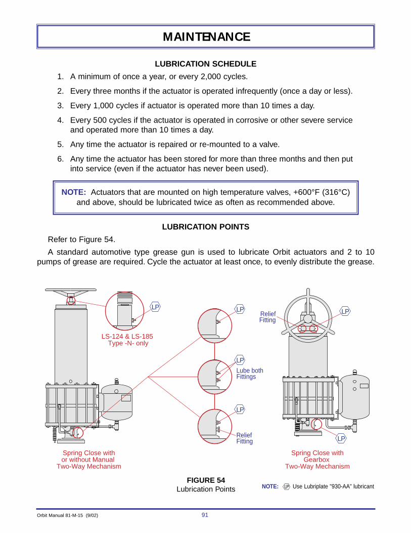
Orbit Manual 81-M-15 (9/02) 91
MAINTENANCE
LUBRICATION SCHEDULE
1. A minimum of once a year, or every 2,000 cycles.
2. Every three months if the actuator is operated infrequently (once a day or less).
3. Every 1,000 cycles if actuator is operated more than 10 times a day.
4. Every 500 cycles if the actuator is operated in corrosive or other severe serviceand operated more than 10 times a day.
5. Any time the actuator is repaired or re-mounted to a valve.
6. Any time the actuator has been stored for more than three months and then putinto service (even if the actuator has never been used).
LUBRICATION POINTS
Refer to Figure 54.
A standard automotive type grease gun is used to lubricate Orbit actuators and 2 to 10pumps of grease are required. Cycle the actuator at least once, to evenly distribute the grease.
NOTE: Actuators that are mounted on high temperature valves, +600°F (316°C)and above, should be lubricated twice as often as recommended above.
LP LP LP
LP
LP
LP
Lube bothFittings
Spring Close withor without Manual
Two-Way Mechanism
LS-124 & LS-185 Type -N- only
Spring Close withGearbox
Two-Way Mechanism
ReliefFitting
ReliefFitting
FIGURE 54Lubrication Points NOTE: Use Lubriplate "930-AA" lubricant
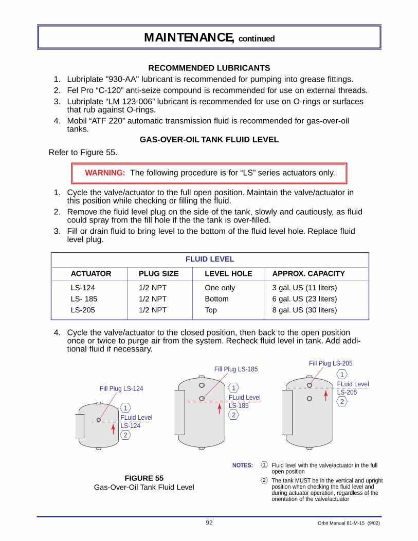
92 Orbit Manual 81-M-15 (9/02)
Fill Plug LS-124
FLuid LevelLS-124
Fill Plug LS-185Fill Plug LS-205
1
2
FLuid LevelLS-185
1
2
FLuid LevelLS-205
1
2
MAINTENANCE, continued
RECOMMENDED LUBRICANTS1. Lubriplate "930-AA" lubricant is recommended for pumping into grease fittings.2. Fel Pro “C-120” anti-seize compound is recommended for use on external threads.3. Lubriplate “LM 123-006” lubricant is recommended for use on O-rings or surfaces
that rub against O-rings.4. Mobil “ATF 220” automatic transmission fluid is recommended for gas-over-oil
tanks.GAS-OVER-OIL TANK FLUID LEVEL
Refer to Figure 55.
1. Cycle the valve/actuator to the full open position. Maintain the valve/actuator inthis position while checking or filling the fluid.
2. Remove the fluid level plug on the side of the tank, slowly and cautiously, as fluidcould spray from the fill hole if the the tank is over-filled.
3. Fill or drain fluid to bring level to the bottom of the fluid level hole. Replace fluidlevel plug.
4. Cycle the valve/actuator to the closed position, then back to the open positiononce or twice to purge air from the system. Recheck fluid level in tank. Add addi-tional fluid if necessary.
WARNING: The following procedure is for “LS” series actuators only.
NOTES: Fluid level with the valve/actuator in the fullopen position
The tank MUST be in the vertical and uprightposition when checking the fluid level andduring actuator operation, regardless of theorientation of the valve/actuator
2
1
FIGURE 55Gas-Over-Oil Tank Fluid Level
FLUID LEVEL
ACTUATOR PLUG SIZE LEVEL HOLE APPROX. CAPACITY
LS-124 1/2 NPT One only 3 gal. US (11 liters)
LS- 185 1/2 NPT Bottom 6 gal. US (23 liters)
LS-205 1/2 NPT Top 8 gal. US (30 liters)
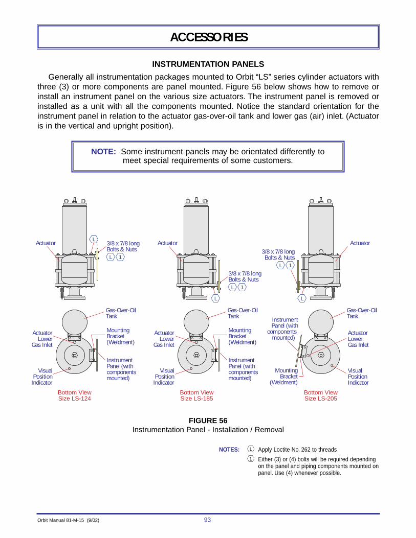
Orbit Manual 81-M-15 (9/02) 93
ACCESSORIES
INSTRUMENTATION PANELS
Generally all instrumentation packages mounted to Orbit “LS” series cylinder actuators withthree (3) or more components are panel mounted. Figure 56 below shows how to remove orinstall an instrument panel on the various size actuators. The instrument panel is removed orinstalled as a unit with all the components mounted. Notice the standard orientation for theinstrument panel in relation to the actuator gas-over-oil tank and lower gas (air) inlet. (Actuatoris in the vertical and upright position).
NOTE: Some instrument panels may be orientated differently to meet special requirements of some customers.
Actuator
ActuatorLower
Gas Inlet
Gas-Over-OilTank
VisualPosition
Indicator
Instrument Panel (with componentsmounted)
3/8 x 7/8 longBolts & Nuts
MountingBracket(Weldment)
L
L
1
ActuatorLowerGas Inlet
Gas-Over-OilTank
VisualPositionIndicator
Instrument Panel (with
components mounted)
MountingBracket
(Weldment)
Actuator
ActuatorLower
Gas Inlet
Gas-Over-OilTank
VisualPosition
Indicator
Instrument Panel (with componentsmounted)
3/8 x 7/8 longBolts & Nuts
MountingBracket(Weldment)
L
L
1
Actuator
Bottom ViewSize LS-124
Bottom ViewSize LS-185
Bottom ViewSize LS-205
3/8 x 7/8 longBolts & Nuts
L
L
1
NOTES: Apply Loctite No. 262 to threads
Either (3) or (4) bolts will be required dependingon the panel and piping components mounted onpanel. Use (4) whenever possible.
1
FIGURE 56Instrumentation Panel - Installation / Removal
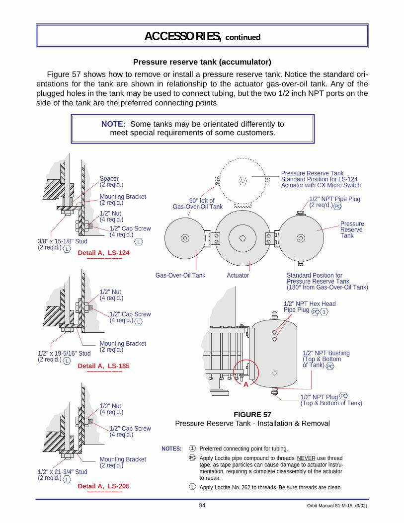
94 Orbit Manual 81-M-15 (9/02)
ACCESSORIES, continued
Pressure reserve tank (accumulator)
Figure 57 shows how to remove or install a pressure reserve tank. Notice the standard ori-entations for the tank are shown in relationship to the actuator gas-over-oil tank. Any of theplugged holes in the tank may be used to connect tubing, but the two 1/2 inch NPT ports on theside of the tank are the preferred connecting points.
NOTE: Some tanks may be orientated differently to meet special requirements of some customers.
������ �
���������
�
�
��
�
�
��
���
�����������������
�
�
���
�������
����������
�
�
����
��
�������
�
�������
Spacer(2 req'd.)
Pressure Reserve TankStandard Position for LS-124Actuator with CX Micro Switch
90° left of Gas-Over-Oil Tank
Gas-Over-Oil Tank Actuator Standard Position forPressure Reserve Tank(180° from Gas-Over-Oil Tank)
Mounting Bracket(2 req'd.) 1/2" NPT Pipe Plug
(2 req'd.)
PressureReserveTank
1/2" Nut(4 req'd.)
1/2" Cap Screw(4 req'd.)
3/8" x 15-1/8" Stud(2 req'd.)
L
L
PC
Detail A, LS-205––––––––––
Detail A, LS-185 ––––––––––
Detail A, LS-124 ––––––––––
A
Mounting Bracket(2 req'd.)
1/2" Nut(4 req'd.)
1/2" Cap Screw(4 req'd.)
1/2" x 19-5/16" Stud(2 req'd.) L
L
Mounting Bracket(2 req'd.)
1/2" Nut(4 req'd.)
1/2" Cap Screw(4 req'd.)
1/2" x 21-3/4" Stud(2 req'd.) L
1/2" NPT Hex HeadPipe Plug
1/2" NPT Bushing(Top & Bottomof Tank)
PC 1
PC
1/2" NPT Plug(Top & Bottom of Tank)
PC
NOTES: Preferred connecting point for tubing.
Apply Loctite pipe compound to threads. NEVER use threadtape, as tape particles can cause damage to actuator instru-mentation, requiring a complete disassembly of the actuatorto repair.
Apply Loctite No. 262 to threads. Be sure threads are clean.
1
FIGURE 57Pressure Reserve Tank - Installation & Removal

Orbit Manual 81-M-15 (9/02) 95
ACCESSORIES, continued
ELECTRIC CX MICRO SWITCH
The standard type CX micro switch is a weather-tight, explosion proof limit switch availablein two (2) or four (4) circuit models.
INSTALLATION (CX MICRO SWITCH)
Refer to Figure 58.
1. Attach micro switch (Item 1) on mounting bracket (Item 2) with four (4) nuts & bolts(Item 3).
2. Slip actuator arm (Item 4) into arm clamp (Item 5) to micro switch shaft with socketset screw (Item 6).
3. Attach arm clamp (Item 5) and actuator arm (Item 4) to micro switch shaft withsocket set screw (Item 6).
4. Notice the position of the switch assembly in the figure, and remove the two (2)studs & nuts or bolts & nuts (Item 7). Install the mounting bracket with the switchand re-install the studs & nuts or bolts & nuts. (NOTE: Be sure bolts or studs havesufficient thread length. If necessary replace them with longer ones.)
5. Loosen pointer clamp (Item 8) and bottom of rod boot (Item 14).
6. Remove two (2) set screws (Item 9) and collar (Item 10).
7. Attach actuating arm guide (Item 11) to lower threaded hole of actuating clamp(Item 10) with shoulder screw (Item 12). (NOTE: Collar (Item 10) without threadedhole, will not be re-used.)
8. Slip actuator arm (Item 4) thru actuating arm guide (Item 11).
9. Attach and align actuating clamp (Item 10) and actuating arm guide (Item 11) toVPI rod (Item 13) by tightening set screw (Item 9).
10. Slip the end of the rod boot (Item 14) over the actuating clamp (Item 10) so thatthe distance from the bottom of the actuating clamp to the bottom of the rod bootis 1-5/8 (1.62) inch (41 mm) and the bottom of the rod boot to the bottom of thepointer clamp (Item 8) is 1/8 (.12) inch (3 mm). Then tighten the pointer clamp.
11. Remove switch cover and attach conduit to one or both 3/4 NPT holes in switchhousing as required. Refer to applicable wiring diagram for wiring connections.(NOTE: Pipe plug (Item 15) is used to plug 3/4 NPT hole in switch housing if bothholes are not used.)
12. Assembly is now ready to have switches adjusted.

96 Orbit Manual 81-M-15 (9/02)
ACCESSORIES, continued
Actuator
AdapterPlate Mounting
Bracket
Bonnnet
AdapterFlange
(Threadedor cast to
bonnet)
A
C
7
L6
TC15
L3
5
1
14
13
L 9
8
10
11
2
Actuator
MountingBracket
MountingBracket
Bonnnet
1/8 (.12)(3mm)
1-5/8 (1.62) (41mm)Adapter
Flange(Threadedor cast to
bonnet)
A7
2
CylinderActuator
3/4 NPT -Remove to connect Conduit
Actuator
SleeveMountingBracket
IndicatorPlate
Bracket
Bonnnet
AdapterFlange
(Threadedor cast to
bonnet)
A7
L 122
4
8(Ref)
2 (Ref)
Lower Gas Inlet
Bottom ViewMounting Bracket Attachmentsto Various Style Valve Bonnets
1. CX MICRO SWITCH2. MOUNTING BRACKET3. HEX NUT & BOLT (4 REQ'D) (1/4-20)4. ACTUATOR ARM5. ARM CLAMP6 SOCKET SET SCREW (2 REQ'D) (NO. 10-32)7. STUD & NUTS OR BOLT & NUTS8. POINTER CLAMP
9. SET SCREWS (2 REQ'D) (1/4-20)10. ACTUATING CLAMP (COLLAR)11. ACTUATING ARM GUIDE12. SHOULDER SCREW (NO. 10-24)13. VISUAL POSITION INDICATOR ROD14. ROD BOOT15. SHIPPING PLUG (2 REQ'D) (3/4 NPT)
NOTES: TORQUE TO:120 ft-lbs (163 Nm) for 5/8" bolt or stud200 ft-lbs (271 Nm) for 3/4" bolt or stud
Apply Fel-Pro “C-102” Anti-seize compound
Apply Loctite No. 262 to threads
Coat with Lubriplate No. LM123-006
FIGURE 58CX Switch Installation and Removal
PARTS REFERENCE
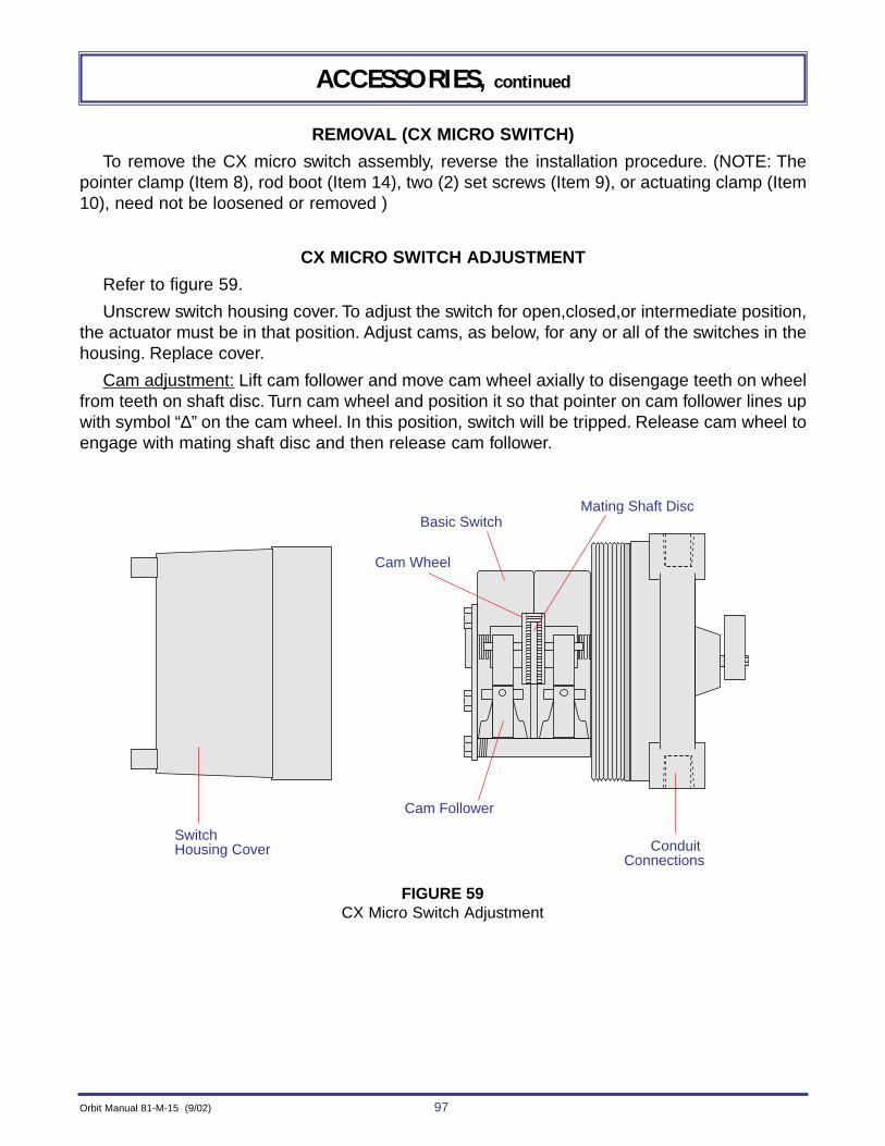
Orbit Manual 81-M-15 (9/02) 97
Mating Shaft Disc
Switch Housing Cover
Basic Switch
Cam Wheel
Cam Follower
Conduit Connections
ACCESSORIES, continued
REMOVAL (CX MICRO SWITCH)
To remove the CX micro switch assembly, reverse the installation procedure. (NOTE: Thepointer clamp (Item 8), rod boot (Item 14), two (2) set screws (Item 9), or actuating clamp (Item10), need not be loosened or removed )
CX MICRO SWITCH ADJUSTMENT
Refer to figure 59.
Unscrew switch housing cover. To adjust the switch for open,closed,or intermediate position,the actuator must be in that position. Adjust cams, as below, for any or all of the switches in thehousing. Replace cover.
Cam adjustment: Lift cam follower and move cam wheel axially to disengage teeth on wheelfrom teeth on shaft disc. Turn cam wheel and position it so that pointer on cam follower lines upwith symbol “∆” on the cam wheel. In this position, switch will be tripped. Release cam wheel toengage with mating shaft disc and then release cam follower.
FIGURE 59CX Micro Switch Adjustment
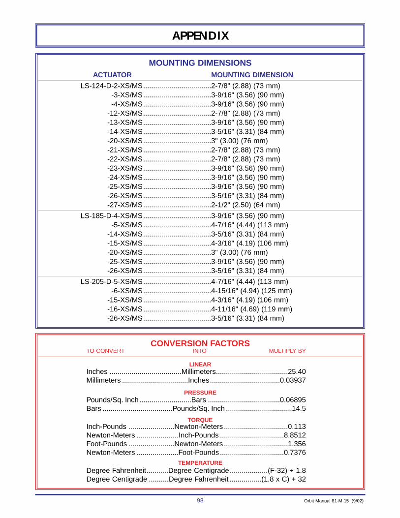
98 Orbit Manual 81-M-15 (9/02)
APPENDIX
MOUNTING DIMENSIONSACTUATOR ..................................MOUNTING DIMENSION
LS-124-D-2-XS/MS..................................2-7/8" (2.88) (73 mm)-3-XS/MS..................................3-9/16" (3.56) (90 mm)-4-XS/MS..................................3-9/16" (3.56) (90 mm)
-12-XS/MS..................................2-7/8" (2.88) (73 mm)-13-XS/MS..................................3-9/16" (3.56) (90 mm)-14-XS/MS..................................3-5/16" (3.31) (84 mm)-20-XS/MS..................................3" (3.00) (76 mm)-21-XS/MS..................................2-7/8" (2.88) (73 mm)-22-XS/MS..................................2-7/8" (2.88) (73 mm)-23-XS/MS..................................3-9/16" (3.56) (90 mm)-24-XS/MS..................................3-9/16" (3.56) (90 mm)-25-XS/MS..................................3-9/16" (3.56) (90 mm)-26-XS/MS..................................3-5/16" (3.31) (84 mm)-27-XS/MS..................................2-1/2" (2.50) (64 mm)
LS-185-D-4-XS/MS..................................3-9/16" (3.56) (90 mm)-5-XS/MS..................................4-7/16" (4.44) (113 mm)
-14-XS/MS..................................3-5/16" (3.31) (84 mm)-15-XS/MS..................................4-3/16" (4.19) (106 mm)-20-XS/MS..................................3" (3.00) (76 mm)-25-XS/MS..................................3-9/16" (3.56) (90 mm)-26-XS/MS..................................3-5/16" (3.31) (84 mm)
LS-205-D-5-XS/MS..................................4-7/16" (4.44) (113 mm)-6-XS/MS..................................4-15/16" (4.94) (125 mm)
-15-XS/MS..................................4-3/16" (4.19) (106 mm)-16-XS/MS..................................4-11/16" (4.69) (119 mm)-26-XS/MS..................................3-5/16" (3.31) (84 mm)
CONVERSION FACTORSTO CONVERT INTO MULTIPLY BY
LINEARInches ....................................Millimeters....................................25.40Millimeters .................................Inches...................................0.03937
PRESSUREPounds/Sq. Inch..........................Bars ....................................0.06895Bars ...................................Pounds/Sq. Inch .................................14.5
TORQUEInch-Pounds .......................Newton-Meters ................................0.113Newton-Meters .....................Inch-Pounds ................................8.8512Foot-Pounds .......................Newton-Meters ................................1.356Newton-Meters .....................Foot-Pounds ................................0.7376
TEMPERATUREDegree Fahrenheit...........Degree Centigrade...................(F-32) ÷ 1.8Degree Centigrade ..........Degree Fahrenheit ................(1.8 x C) + 32

Orbit Manual 81-M-15 (9/02) 99
ASIA, FAR EAST, INDIAN
SUB-CONTINENTCOOPER CAMERON VALVES
2 Gul Circle, Jurong Industrial EstateSingapore 629560
Telephone (65) 6861-3355Facsimile (65) 6861-7109
AUSTRALIA AND NEW ZEALAND
COOPER CAMERON VALVES283 Burbridge Road
Suite 43Brooklyn Park 5032
South AustraliaTelephone (61) 8 8352-3077Facsimile (61) 8 8352-3066
ORBIT VALVE Division of Cooper Cameron Valves
7200 Interstate 30 • Little Rock,Arkansas,72209 U.S.A.Telephone (1) 501-568-6000 • Wats (1) 800 643-6544 • Facsimile (1) 501-570-5700
e-mail:[email protected]
ORBIT VALVE UNITED STATES FACILITIES
SALES REPRESENTATIVES IN THESE U.S. LOCATIONS:
ARKANSASP.O. Box 193520
Little Rock, Arkansas 72219 U.S.A.Telephone (1) 501-568-6000
WATS (1) 800-643-6544Facsimile (1) 501-570-5700
TEXAS16500 South Main
Missouri City, Texas 77489 U.S.A.Telephone (1) 281-261-3742
WATS (1) 800-252-4618Facsimile (1) 281-261-3749
MOBILE, ALABAMALITTLE ROCK, ARKANSAS
BAKERSFIELD, CALIFORNIALOS ANGELES, CALIFORNIA
SAN FRANCISCO, CALIFORNIADENVER, COLORADO
ATLANTA, GEORGIALAFAYETTE, LOUISIANA
NEW ORLEANS, LOUISIANATRAVERSE CITY, MICHIGAN
ST. LOUIS, MISSOURICOLUMBUS, OHIO
TULSA, OKLAHOMA
PHILADELPHIA, PENNSYLVANIACORPUS CHRISTI, TEXAS
HOUSTON, TEXASODESSA, TEXASTYLER, TEXAS
CASPER, WYOMING
CENTRAL AMERICASOUTH AMERICA
AND MEXICOORBIT VALVE 16500 South Main
Missouri City, Texas 77489 U.S.A.Telephone (1) 281-261-3742
WATS (1) 800-252-4618Facsimile (1) 281-261-3749
EUROPE, AFRICAAND MIDDLE EAST
COOPER CAMERON VALVESHoustoun Road, Livingston,
West Lothian, EH54 5BZScotland
Telephone: (44) 01506 832000Facsimile: (44) 01506 441320
CANADAORBIT VALVE
#600, 715 7th Avenue S.W.Calgary, Alberta, Canada
T2P2X6Telephone (1) 403-398-9930Facsimile (1) 403-398-9936
–––––––––––––––––
ORBIT VALVEDIVISION OF
COOPERCAMERON
VALVESOrbit is a Trademark of Cooper Cameron Corporation, Cooper Cameron Valves Division © Copyright 2002,
Cooper Cameron Corporation, Cooper Cameron Valves Division