Installation and maintenance instructions - bosch … · 13.2 Testing the flue system, including...
80
6304 0308 – 04/2005 US For heating engineers Please read carefully prior to installation and maintenance. Installation and maintenance instructions Gas boiler Logano G124X II/SP CAUTION! Observe the safety instructions of this installation and maintenance manual before placing the boiler in operation. WARNING! If installation, adjustment, modification, operation or maintenance of the heating system is carried out by an unqualified person, this may result in danger to life and limb or property damage. The directions of this installation and maintenance manual must be followed precisely. Contact a qualified service company, service provider or the gas company if support or additional information is required. CAUTION! The operating manual is a component of the technical documentation handed over to the operator of the heating system. Discuss the instruction in this manual with the owner or operator of the heating system to ensure that they are familiar with all information required for operation of the heating system. Note: Keep this installation and maintenance manual available for future reference.
Transcript of Installation and maintenance instructions - bosch … · 13.2 Testing the flue system, including...

6304 0308 – 04/2005 US For heating engineers
Please read carefully prior to installation and maintenance.
Installation and maintenance instructions
Gas boilerLogano G124X II/SP
CAUTION!Observe the safety instructions of this installation and maintenance manual before placing the boiler in operation.
WARNING!If installation, adjustment, modification, operation or maintenance of the heating system is carried out by an unqualified person, this may result in danger to life and limb or property damage. The directions of this installation and maintenance manual must be followed precisely. Contact a qualified service company, service provider or the gas company if support or additional information is required.
CAUTION!The operating manual is a component of the technical documentation handed over to the operator of the heating system. Discuss the instruction in this manual with the owner or operator of the heating system to ensure that they are familiar with all information required for operation of the heating system.
Note: Keep this installation and maintenance manual available for future reference.

Contents
1 Safety. . . . . . . . . . . . . . . . . . . . . . . . . . . . . . . . . . . . . . . . . . . . . . . . . . . . . 4
1.1 Correct use . . . . . . . . . . . . . . . . . . . . . . . . . . . . . . . . . . . . . . . . . . . . . . . 4
1.2 Observe the following symbols . . . . . . . . . . . . . . . . . . . . . . . . . . . . . . . . . . . 4
1.3 Please observe these notes . . . . . . . . . . . . . . . . . . . . . . . . . . . . . . . . . . . . . . 4
1.4 Tools, materials and accessories . . . . . . . . . . . . . . . . . . . . . . . . . . . . . . . . . 6
1.5 Disposal . . . . . . . . . . . . . . . . . . . . . . . . . . . . . . . . . . . . . . . . . . . . . . . . . 6
2 Product description . . . . . . . . . . . . . . . . . . . . . . . . . . . . . . . . . . . . . . . . . . 7
3 Dimensions and connections . . . . . . . . . . . . . . . . . . . . . . . . . . . . . . . . . . 8
4 Scope of delivery . . . . . . . . . . . . . . . . . . . . . . . . . . . . . . . . . . . . . . . . . . . . 9
5 Moving the boiler . . . . . . . . . . . . . . . . . . . . . . . . . . . . . . . . . . . . . . . . . . . 10
5.1 Moving the boiler with boiler cart . . . . . . . . . . . . . . . . . . . . . . . . . . . . . . . . . 10
5.2 Lifting and carrying the boiler . . . . . . . . . . . . . . . . . . . . . . . . . . . . . . . . . . . 11
6 Placing the boiler . . . . . . . . . . . . . . . . . . . . . . . . . . . . . . . . . . . . . . . . . . . 12
6.1 Clearances . . . . . . . . . . . . . . . . . . . . . . . . . . . . . . . . . . . . . . . . . . . . . . 12
6.2 Leveling the boiler . . . . . . . . . . . . . . . . . . . . . . . . . . . . . . . . . . . . . . . . . . 12
7 Boiler installation. . . . . . . . . . . . . . . . . . . . . . . . . . . . . . . . . . . . . . . . . . . 13
7.1 Preparing for installation . . . . . . . . . . . . . . . . . . . . . . . . . . . . . . . . . . . . . . 13
7.2 Connecting the heating system. . . . . . . . . . . . . . . . . . . . . . . . . . . . . . . . . . 14
7.3 Electrical connection . . . . . . . . . . . . . . . . . . . . . . . . . . . . . . . . . . . . . . . . 16
7.4 Installation of Logamatic 2107 control (accessory) . . . . . . . . . . . . . . . . . . . . . . 17
7.5 Fuel supply connection. . . . . . . . . . . . . . . . . . . . . . . . . . . . . . . . . . . . . . . 21
7.6 Filling heating system and checking for leaks . . . . . . . . . . . . . . . . . . . . . . . . . 23
8 Check openings for combustion air supply and venting . . . . . . . . . . . . . 24
9 Requirements for connection to chimneys or venting systems . . . . . . . 25
10 Flue pipe installation . . . . . . . . . . . . . . . . . . . . . . . . . . . . . . . . . . . . . . . . 26
11 Placing the heating system in operation . . . . . . . . . . . . . . . . . . . . . . . . . 28
11.1 Start-up instructions. . . . . . . . . . . . . . . . . . . . . . . . . . . . . . . . . . . . . . . . . 30
11.2 Making G124X II and G124X SP boilers ready for operation . . . . . . . . . . . . . . . 31
11.3 Conducting final commissioning for G124X II boiler . . . . . . . . . . . . . . . . . . . . . 32
11.4 Conducting final commissioning for G124X SP boiler . . . . . . . . . . . . . . . . . . . . 36
11.5 Shutting off gas supply to boiler . . . . . . . . . . . . . . . . . . . . . . . . . . . . . . . . . 40
11.6 Instruct owner/operator and hand over technical documentation . . . . . . . . . . . . . 41
11.7 Start-up protocol . . . . . . . . . . . . . . . . . . . . . . . . . . . . . . . . . . . . . . . . . . . 42
12 Taking the boiler out of operation . . . . . . . . . . . . . . . . . . . . . . . . . . . . . . 43
12.1 Normal boiler shut-down . . . . . . . . . . . . . . . . . . . . . . . . . . . . . . . . . . . . . . 43
12.2 Emergency shut-down . . . . . . . . . . . . . . . . . . . . . . . . . . . . . . . . . . . . . . . 43
2 Installation and maintenance instructions Logano G124X II/SP special gas-fired boiler • Issue 04/2005
We reserve the right to make any changes due to technical modifications.

Contents
13 Boiler inspection and maintenance. . . . . . . . . . . . . . . . . . . . . . . . . . . . . . 44
13.1 Why is regular maintenance important? . . . . . . . . . . . . . . . . . . . . . . . . . . . . . 44
13.2 Testing the flue system, including combustion air, air inlets and ventilation openings . 44
13.3 Inspection of the boiler and burner . . . . . . . . . . . . . . . . . . . . . . . . . . . . . . . . 44
13.4 Preparing boiler for cleaning . . . . . . . . . . . . . . . . . . . . . . . . . . . . . . . . . . . . 44
13.5 Cleaning the boiler . . . . . . . . . . . . . . . . . . . . . . . . . . . . . . . . . . . . . . . . . . 45
13.6 Cleaning the burner . . . . . . . . . . . . . . . . . . . . . . . . . . . . . . . . . . . . . . . . . 48
13.7 Troubleshooting on the G124X II . . . . . . . . . . . . . . . . . . . . . . . . . . . . . . . . . 49
13.8 Troubleshooting on the G124X SP . . . . . . . . . . . . . . . . . . . . . . . . . . . . . . . . 51
13.9 Maintenance protocol . . . . . . . . . . . . . . . . . . . . . . . . . . . . . . . . . . . . . . . . 53
14 Parts lists . . . . . . . . . . . . . . . . . . . . . . . . . . . . . . . . . . . . . . . . . . . . . . . . . 55
15 Specifications . . . . . . . . . . . . . . . . . . . . . . . . . . . . . . . . . . . . . . . . . . . . . . 73
16 Wiring diagrams . . . . . . . . . . . . . . . . . . . . . . . . . . . . . . . . . . . . . . . . . . . . 74
3
We reserve the right to make any changes due to technical modifications.
Installation and maintenance instructions Logano G124X II/SP special gas-fired boiler • Issue 04/2005
Safety1
1 Safety
Observe these instructions for your safety.
The burner and control must be correctly installed and adjusted to ensure safe and economical operation of the special gas-fired boiler.
Read this installation and maintenance manual carefully and note the details on the boiler nameplate before placing the boiler in operation.
1.1 Correct use
The Logano G124X II/SP special gas-fired boiler is designed to heat water for a hot water heating system for heating single or multiple occupancy buildings.
1.2 Observe the following symbols
Two levels of danger are identified and signified by the following terms:
Additional symbols for identification of dangers and user instructions:.
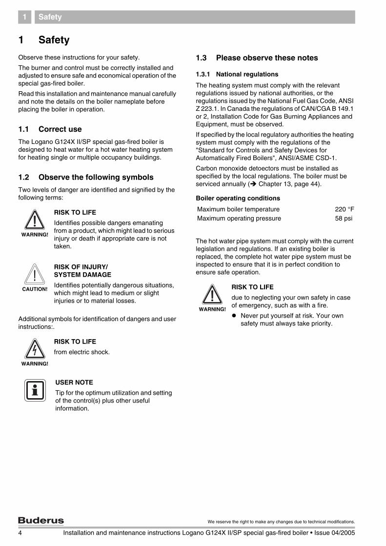
1.3 Please observe these notes
1.3.1 National regulations
The heating system must comply with the relevant regulations issued by national authorities, or the regulations issued by the National Fuel Gas Code, ANSI Z 223.1. In Canada the regulations of CAN/CGA B 149.1 or 2, Installation Code for Gas Burning Appliances and Equipment, must be observed.
If specified by the local regulatory authorities the heating system must comply with the regulations of the "Standard for Controls and Safety Devices for Automatically Fired Boilers", ANSI/ASME CSD-1.
Carbon monoxide detoectors must be installed as specified by the local regulations. The boiler must be serviced annually ( Chapter 13, page 44).
Boiler operating conditions
The hot water pipe system must comply with the current legislation and regulations. If an existing boiler is replaced, the complete hot water pipe system must be inspected to ensure that it is in perfect condition to ensure safe operation.
WARNING!
RISK TO LIFE
Identifies possible dangers emanating from a product, which might lead to serious injury or death if appropriate care is not taken.
CAUTION!
RISK OF INJURY/ SYSTEM DAMAGE
Identifies potentially dangerous situations, which might lead to medium or slight injuries or to material losses.
WARNING!
RISK TO LIFE
from electric shock.
USER NOTE
Tip for the optimum utilization and setting of the control(s) plus other useful information.
Maximum boiler temperature 220 °FMaximum operating pressure 58 psi
WARNING!
RISK TO LIFE
due to neglecting your own safety in case of emergency, such as with a fire.
Never put yourself at risk. Your own safety must always take priority.
4 Installation and maintenance instructions Logano G124X II/SP special gas-fired boiler • Issue 04/2005
We reserve the right to make any changes due to technical modifications.
Safety 1
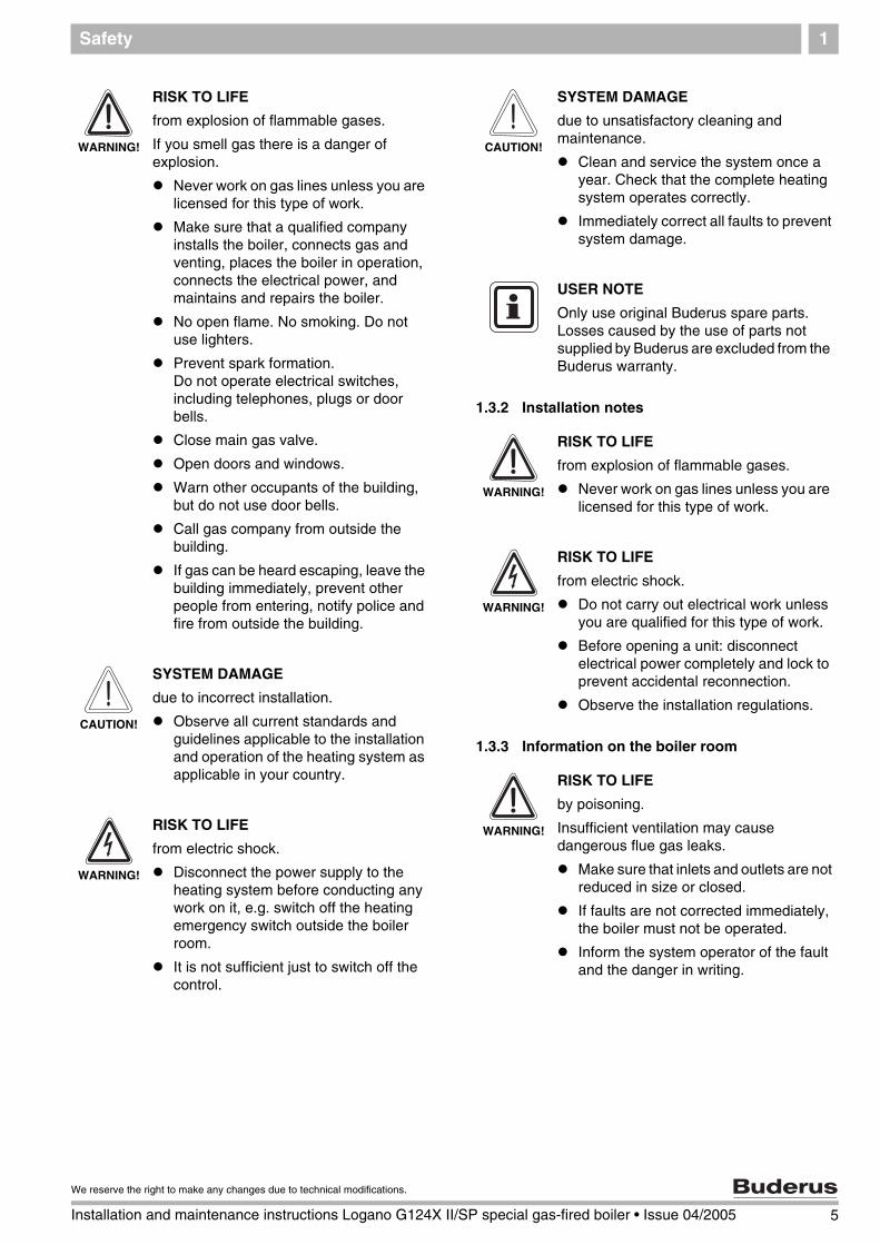
1.3.2 Installation notes
1.3.3 Information on the boiler room
WARNING!
RISK TO LIFE
from explosion of flammable gases.
If you smell gas there is a danger of explosion.
Never work on gas lines unless you are licensed for this type of work.Make sure that a qualified company installs the boiler, connects gas and venting, places the boiler in operation, connects the electrical power, and maintains and repairs the boiler.
No open flame. No smoking. Do not use lighters.
Prevent spark formation.Do not operate electrical switches, including telephones, plugs or door bells.
Close main gas valve.
Open doors and windows.
Warn other occupants of the building, but do not use door bells.
Call gas company from outside the building.
If gas can be heard escaping, leave the building immediately, prevent other people from entering, notify police and fire from outside the building.
CAUTION!
SYSTEM DAMAGE
due to incorrect installation.
Observe all current standards and guidelines applicable to the installation and operation of the heating system as applicable in your country.
WARNING!
RISK TO LIFE
from electric shock.
Disconnect the power supply to the heating system before conducting any work on it, e.g. switch off the heating emergency switch outside the boiler room.
It is not sufficient just to switch off the control.
CAUTION!
SYSTEM DAMAGE
due to unsatisfactory cleaning and maintenance.
Clean and service the system once a year. Check that the complete heating system operates correctly.
Immediately correct all faults to prevent system damage.
USER NOTE
Only use original Buderus spare parts. Losses caused by the use of parts not supplied by Buderus are excluded from the Buderus warranty.
WARNING!
RISK TO LIFE
from explosion of flammable gases.
Never work on gas lines unless you are licensed for this type of work.
WARNING!
RISK TO LIFE
from electric shock.
Do not carry out electrical work unless you are qualified for this type of work.
Before opening a unit: disconnect electrical power completely and lock to prevent accidental reconnection.
Observe the installation regulations.
WARNING!
RISK TO LIFE
by poisoning.
Insufficient ventilation may cause dangerous flue gas leaks.
Make sure that inlets and outlets are not reduced in size or closed.
If faults are not corrected immediately, the boiler must not be operated.
Inform the system operator of the fault and the danger in writing.
5
We reserve the right to make any changes due to technical modifications.
Installation and maintenance instructions Logano G124X II/SP special gas-fired boiler • Issue 04/2005
Safety1
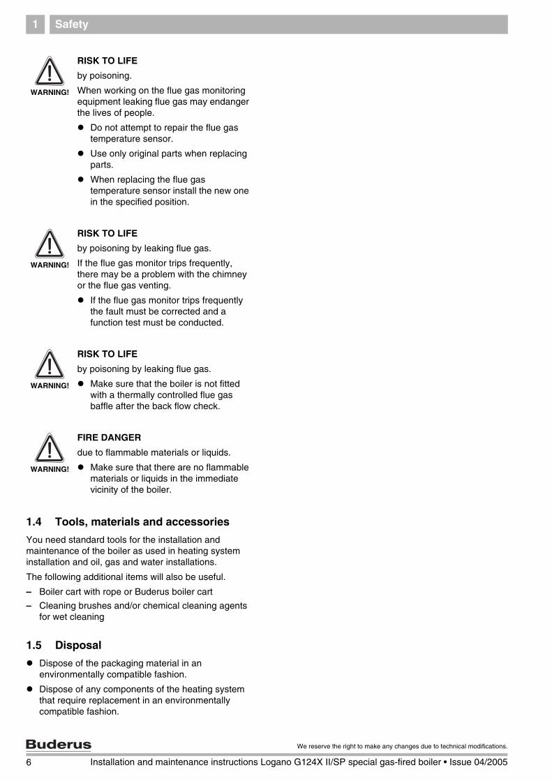
1.4 Tools, materials and accessories
You need standard tools for the installation and maintenance of the boiler as used in heating system installation and oil, gas and water installations.
The following additional items will also be useful.
– Boiler cart with rope or Buderus boiler cart
– Cleaning brushes and/or chemical cleaning agents for wet cleaning
1.5 Disposal
Dispose of the packaging material in an environmentally compatible fashion.
Dispose of any components of the heating system that require replacement in an environmentally compatible fashion.
WARNING!
RISK TO LIFE
by poisoning.
When working on the flue gas monitoring equipment leaking flue gas may endanger the lives of people.
Do not attempt to repair the flue gas temperature sensor.
Use only original parts when replacing parts.
When replacing the flue gas temperature sensor install the new one in the specified position.
WARNING!
RISK TO LIFE
by poisoning by leaking flue gas.
If the flue gas monitor trips frequently, there may be a problem with the chimney or the flue gas venting.
If the flue gas monitor trips frequently the fault must be corrected and a function test must be conducted.
WARNING!
RISK TO LIFE
by poisoning by leaking flue gas.
Make sure that the boiler is not fitted with a thermally controlled flue gas baffle after the back flow check.
WARNING!
FIRE DANGER
due to flammable materials or liquids.
Make sure that there are no flammable materials or liquids in the immediate vicinity of the boiler.
6 Installation and maintenance instructions Logano G124X II/SP special gas-fired boiler • Issue 04/2005
We reserve the right to make any changes due to technical modifications.
Product description 2
7
We reserve the right to make any changes due to technical modifications.
Installation and maintenance instructions Logano G124X II/SP special gas-fired boiler • Issue 04/2005
2 Product description
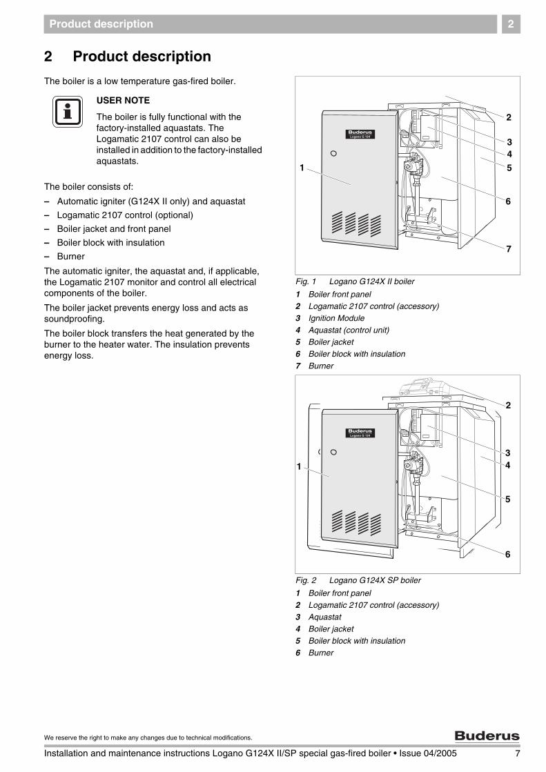
The boiler is a low temperature gas-fired boiler.
The boiler consists of:
– Automatic igniter (G124X II only) and aquastat
– Logamatic 2107 control (optional)
– Boiler jacket and front panel
– Boiler block with insulation
– Burner
The automatic igniter, the aquastat and, if applicable, the Logamatic 2107 monitor and control all electrical components of the boiler.
The boiler jacket prevents energy loss and acts as soundproofing.
The boiler block transfers the heat generated by the burner to the heater water. The insulation prevents energy loss.
Fig. 1 Logano G124X II boiler
1 Boiler front panel2 Logamatic 2107 control (accessory)
3 Ignition Module
4 Aquastat (control unit)5 Boiler jacket
6 Boiler block with insulation
7 Burner
7
1
6
4
5
3
2
USER NOTE
The boiler is fully functional with the factory-installed aquastats. The Logamatic 2107 control can also be installed in addition to the factory-installed aquastats.
Fig. 2 Logano G124X SP boiler
1 Boiler front panel2 Logamatic 2107 control (accessory)
3 Aquastat
4 Boiler jacket5 Boiler block with insulation
6 Burner
134
5
6
2

8 Installation and maintenance instructions Logano G124X II/SP special gas-fired boiler • Issue 04/2005
We reserve the right to make any changes due to technical modifications.
Dimensions and connections3
3 Dimensions and connections
Tab. 1 Dimensions
Fig. 3 Back, side and front view, measurements in inches
RK 1"
VK 1" GAS ½"
EL ¾"
A
1 2/5"
10 7/8"10 7/8"
23 7/8"
Vent
2/3" - 1 2/5"22"
23 2/3"
33 1/3"
38 1/2"
37"
Connections (measurements see the following tables):VK = Boiler supplyRK = Boiler return EL = Drain GAS = Gas connection
Boiler size Boiler output A Flue connection II/SP
Min. overflow valve capacity
Number ofNozzles
Watervolume
Empty weight
MBtu/hr Inches Inches lb/hr Qty US gal. lbs
18 74 29 2/5" 5" 62 2 2.4 229
25 103 30 1/5" 5" 86 3 2.9 240
32 132,5 30 7/8" 6" 110 4 3.4 337
Fig. 4 Pressure drop
pres
sure
dro
p
flow rate in GPM
USER NOTE
For the size and dimensions of the main gas orifices see Chapter 15, page 73.

Scope of delivery 4
9
We reserve the right to make any changes due to technical modifications.
Installation and maintenance instructions Logano G124X II/SP special gas-fired boiler • Issue 04/2005
4 Scope of delivery
Check packaging on delivery for damage.
Check delivery for completeness.
Component Qty Packaging
Boiler, complete 1 1 pallet
B-kit components:- supply manifold- 30 psi relief valve- boiler drain (¾")- pressure/temperature gauge- 90° elbow (1" NPT)- 90° elbow (¾" NPT)- screw-in feet (4)
1 1 foil package1
Technical documents 1 foil package
Tab. 2 Scope of delivery
1 On pallet
Accessories1 Unit
Logamatic 2107 control 1
Heat circulation pump 1
Cleaning brush 1
Vertical flue system 1
Tab. 3 Scope of delivery
1 Accessories available by separate order
Moving the boiler5
5 Moving the boiler
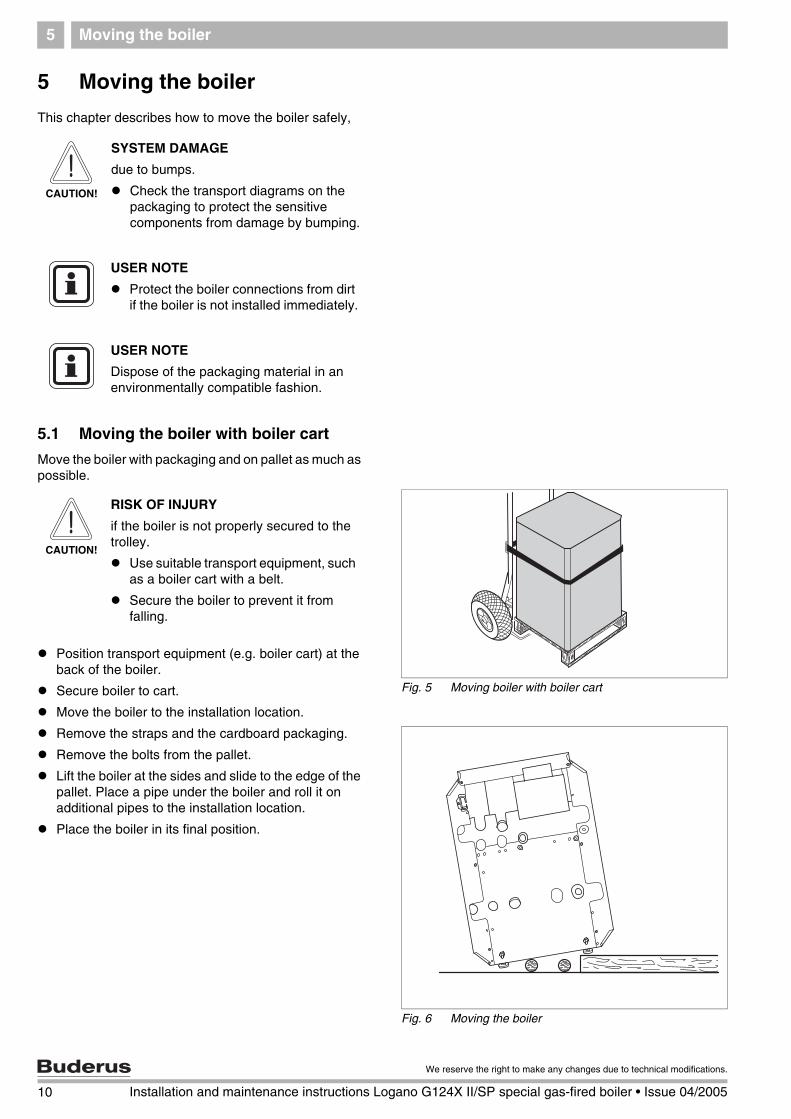
This chapter describes how to move the boiler safely,
5.1 Moving the boiler with boiler cart
Move the boiler with packaging and on pallet as much as possible.
Position transport equipment (e.g. boiler cart) at the back of the boiler.
Secure boiler to cart.
Move the boiler to the installation location.
Remove the straps and the cardboard packaging.
Remove the bolts from the pallet.
Lift the boiler at the sides and slide to the edge of the pallet. Place a pipe under the boiler and roll it on additional pipes to the installation location.
Place the boiler in its final position.
CAUTION!
SYSTEM DAMAGE
due to bumps.
Check the transport diagrams on the packaging to protect the sensitive components from damage by bumping.
USER NOTE
Protect the boiler connections from dirt if the boiler is not installed immediately.
USER NOTE
Dispose of the packaging material in an environmentally compatible fashion.
Fig. 5 Moving boiler with boiler cart
CAUTION!
RISK OF INJURY
if the boiler is not properly secured to the trolley.
Use suitable transport equipment, such as a boiler cart with a belt.
Secure the boiler to prevent it from falling.
Fig. 6 Moving the boiler
10 Installation and maintenance instructions Logano G124X II/SP special gas-fired boiler • Issue 04/2005
We reserve the right to make any changes due to technical modifications.
Moving the boiler 5
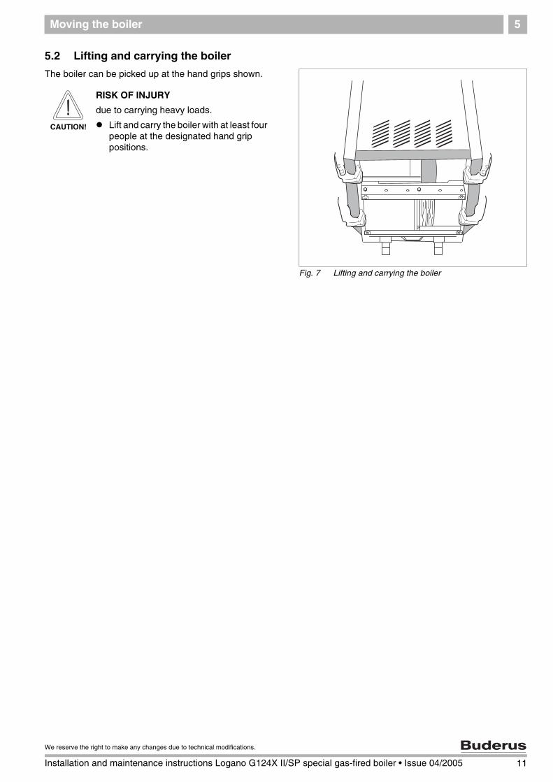
5.2 Lifting and carrying the boiler
The boiler can be picked up at the hand grips shown.
Fig. 7 Lifting and carrying the boiler
CAUTION!
RISK OF INJURY
due to carrying heavy loads.
Lift and carry the boiler with at least four people at the designated hand grip positions.
11
We reserve the right to make any changes due to technical modifications.
Installation and maintenance instructions Logano G124X II/SP special gas-fired boiler • Issue 04/2005

12 Installation and maintenance instructions Logano G124X II/SP special gas-fired boiler • Issue 04/2005
We reserve the right to make any changes due to technical modifications.
Placing the boiler6
6 Placing the boiler
This chapter explains how to place the boiler and position it in the boiler room.
The boiler is very heavy when full. Check that the floor can bear the weight before installation.
6.1 Clearances
A space of at least 33 inches is required in front of the boiler with the door open to allow sufficient access space for operation and maintenance. When the door is closed, a minimum clearance of 2 inches is required at the front and sides, 2 inches clearance is also required for the flue pipe and 30 inches clearance to the ceiling. The installation location and the base must be smooth and horizontal. The boiler may be installed on a flammable base, but not on carpet.
6.2 Leveling the boiler
Screw the four rubber feet 0.25 to 1.0 inches into the bottom rails.
Place boiler on the feet.
Level boiler horizontally and vertically by screwing the feet in and out.
CAUTION!
SYSTEM DAMAGE
through frost.
Place the boiler in a frost-free room.
Fig. 8 Required clearances in the boiler room
1 Door closed2 Door open
3 Flue pipe
min. 2"
min. 2"
min. 2"
1
2
33"
min. 6"
3
Fig. 9 Unscrewing screw-in feet
Boiler installation 7
7 Boiler installation
This chapter describes how to install the boiler. This includes the following tasks:
– Connecting the heating system
– Electrical connection
– Fuel supply connection
7.1 Preparing for installation
Unpack all boxes and containers and check all parts against the packing lists to make sure that everything has been supplied.
USER NOTE
Every boiler is carefully inspected and tested before it leaves the factory. However, if you discover any damage or missing parts, please inform the supplier immediately. Before disposing of packing material, make sure that no parts are still in it.
13
We reserve the right to make any changes due to technical modifications.
Installation and maintenance instructions Logano G124X II/SP special gas-fired boiler • Issue 04/2005

Boiler installation7
7.2 Connecting the heating system
Fig. 10 Low-water alarm
1 Boiler
2 Radiator
3 Heating system with low-water cutoff4 Heating system without low-water cutoff
1
2
2
12
2
2
2
3
4
CAUTION!
BOILER DAMAGE
through moisture.
Protect the components of the gas ignition system from moisture (dripping, spray, rain) during installation of the boiler, during operation and during maintenance work (such as replacing the pump, replacing the control, etc.).
CAUTION!
SYSTEM DAMAGE
due to overheating as a result of low water.
Note that a boiler installed above the level of the heating system must be fitted with a low-water cutoff. The low-water cutoff must be installed during installation of the boiler ( Fig. 10).
CAUTION!
SYSTEM DAMAGE
due to high temperature variations in the heating system.
If the boiler is operated in connection with a refrigeration system, make sure that the pipes for the refrigerated liquid are connected in parallel to the boiler system with suitable valves to prevent the refrigerated liquid from entering the boiler.
The pipe system of a boiler connected to the heating coils of hot-air heating systems that may be exposed to the circulation of cooled air must be fitted with a flow-control valve or some other automatic system for preventing the boiler water from circulating by gravity during the cooling cycle.
14 Installation and maintenance instructions Logano G124X II/SP special gas-fired boiler • Issue 04/2005
We reserve the right to make any changes due to technical modifications.

Boiler installation 7
Installation of B-kit
The relief valve and the pressure/temperature gauge are mounted on the boiler supply VK over the supply manifold (included in B-kit).
Seal 90° 1" NPT elbow on VK.
Seal supply manifold on 90° 1" NPT elbow. The supply manifold can be mounted vertically or rotated 90° to the right.
Seal temperature/pressure gauge on supply manifold.
Fig. 11 Installation of B-kit
1 Pressure/temperature gauge2 Supply manifold
3 Relief valve 3/4"
4 90° 3/4" elbow5 90° 1" NPT elbow
6 Boiler supply VK
7 B-kit rotated 90° right
1
2 3
4
5
6 7
USER NOTE
Install the relief valve after the leak test ( Chapter 7.6, page 23).
The relief valve must be installed in a vertical position.
The relief valve must also be installed in accordance with the requirements of the ANSI/ASME Boiler and Pressure Vessel Code, Section IV.
USER NOTE
We recommend installing a dirt filter (accessory) in the heater return connection to reduce build-up of debris on the water side.
USER NOTE
Observe the local regulations for connection of boiler systems.
CAUTION!
FIRE DANGER
through frost.
Note that a minimum clearance of two inches is required between pipes carrying hot water and flammable walls in the boiler room.
15
We reserve the right to make any changes due to technical modifications.
Installation and maintenance instructions Logano G124X II/SP special gas-fired boiler • Issue 04/2005
Boiler installation7
7.3 Electrical connection
The electrical connections of the boiler must be manufactured as specified by the local codes and the current regulations of the National Electrical Code, ANSI/NFPA–70.
In Canada the regulations of CSA C 22.1 Canadian Electrical Code, Part 1, must be observed.
The boiler must be grounded as specified by the regulations of the relevant local authorities; otherwise follow the regulations of the National Electrical Code, ANSI/NFPA–70.
Install an ON/OFF switch near the boiler.
Check that the heating system functions correctly after any maintenance work.
USER NOTE
When making the electrical connections follow the circuit diagrams on page 74 to page 78.
WARNING!
RISK TO LIFE
from electric shock.
When conducting maintenance work label all cables before disconnecting them.
If cables are connected incorrectly the system may not operate correctly with possibly dangerous consequences.
16 Installation and maintenance instructions Logano G124X II/SP special gas-fired boiler • Issue 04/2005
We reserve the right to make any changes due to technical modifications.

Boiler installation 7
7.4 Installation of Logamatic 2107 control (accessory)
The boiler is fully functional with the factory-installed aquastats. The Logamatic 2107 control can also be installed in addition to the factory-installed aquastats.
1. Unscrew left and right screws in the side panels, lift front panel up, pull down and remove to the front.
2. Unscrew the two fastening screws on the back boiler jacket. Lift the back boiler jacket and remove to the back.
USER NOTE
Note the following when making electrical connections:
Lay out cables and capillaries carefully.
Do not bend the capillaries during installation.
Never carry out any electrical work on the heating system unless you are licensed for this type of work. If you are not a licensed electrician, have a specialist electrical company make the electrical connections.
Observe the local regulations.
Fig. 12 Removing front panel of boiler
Fig. 13 Removing boiler jacket
17
We reserve the right to make any changes due to technical modifications.
Installation and maintenance instructions Logano G124X II/SP special gas-fired boiler • Issue 04/2005

Boiler installation7
3. Slide the insertion tabs of the control into the oval openings.
4. Slide control toward the boiler front panel.
5. Push to snap plastic tabs of the control into the knock-outs.
6. Remove top cover of control Remove screws from the top cover.
7. Fasten control with sheet-metal screws.
8. Route boiler water sensor cable through the cable opening and unroll to the required length.
Fig. 14 Removing terminal cover
Fig. 15 Installation of Logamatic 2000 control system
1 Screws
1
18 Installation and maintenance instructions Logano G124X II/SP special gas-fired boiler • Issue 04/2005
We reserve the right to make any changes due to technical modifications.
Boiler installation 7
Installation of Logamatic boiler water sensor
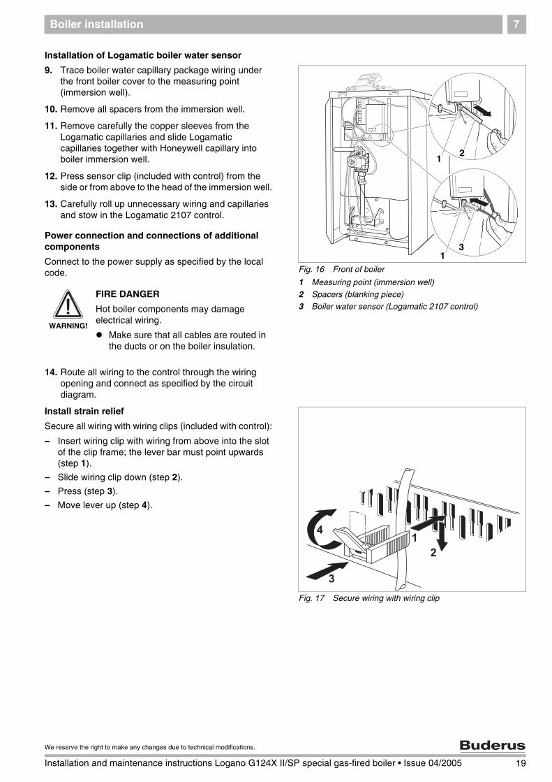
9. Trace boiler water capillary package wiring under the front boiler cover to the measuring point (immersion well).
10. Remove all spacers from the immersion well.
11. Remove carefully the copper sleeves from the Logamatic capillaries and slide Logamatic capillaries together with Honeywell capillary into boiler immersion well.
12. Press sensor clip (included with control) from the side or from above to the head of the immersion well.
13. Carefully roll up unnecessary wiring and capillaries and stow in the Logamatic 2107 control.
Power connection and connections of additional components
Connect to the power supply as specified by the local code.
14. Route all wiring to the control through the wiring opening and connect as specified by the circuit diagram.
Install strain relief
Secure all wiring with wiring clips (included with control):
– Insert wiring clip with wiring from above into the slot of the clip frame; the lever bar must point upwards (step 1).
– Slide wiring clip down (step 2).
– Press (step 3).
– Move lever up (step 4).
Fig. 16 Front of boiler
1 Measuring point (immersion well)
2 Spacers (blanking piece)
3 Boiler water sensor (Logamatic 2107 control)
12
31
WARNING!
FIRE DANGER
Hot boiler components may damage electrical wiring.
Make sure that all cables are routed in the ducts or on the boiler insulation.
Fig. 17 Secure wiring with wiring clip
1
19
We reserve the right to make any changes due to technical modifications.
Installation and maintenance instructions Logano G124X II/SP special gas-fired boiler • Issue 04/2005

Boiler installation7
Install panel components
15. Swivel display unit to the desired position.
16. Position terminal cover and screw to control.
17. Slide tabs of rear boiler cover under the front boiler cover and press down at back.
18. Screw rear boiler cover to rear panel of boiler.
Fig. 18 Swivel display unit
USER NOTE
We recommend positioning the display unit straight on combinations with an L-tank.
Fig. 19 Positioning terminal cover
Fig. 20 Installing rear boiler cover
CAUTION!
SYSTEM DAMAGE
due to dirt.
If the boiler is assembled and not in use, note the following:
Protect the boiler connections from dirt by closing the connections.
20 Installation and maintenance instructions Logano G124X II/SP special gas-fired boiler • Issue 04/2005
We reserve the right to make any changes due to technical modifications.
Boiler installation 7
7.5 Fuel supply connection
7.5.1 Gas connections
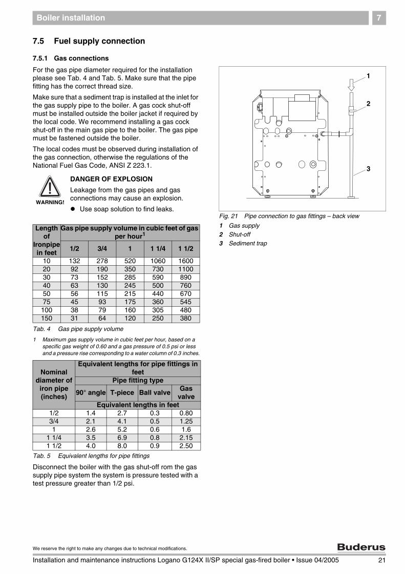
For the gas pipe diameter required for the installation please see Tab. 4 and Tab. 5. Make sure that the pipe fitting has the correct thread size.
Make sure that a sediment trap is installed at the inlet for the gas supply pipe to the boiler. A gas cock shut-off must be installed outside the boiler jacket if required by the local code. We recommend installing a gas cock shut-off in the main gas pipe to the boiler. The gas pipe must be fastened outside the boiler.
The local codes must be observed during installation of the gas connection, otherwise the regulations of the National Fuel Gas Code, ANSI Z 223.1.
Tab. 4 Gas pipe supply volume
1 Maximum gas supply volume in cubic feet per hour, based on a specific gas weight of 0.60 and a gas pressure of 0.5 psi or less and a pressure rise corresponding to a water column of 0.3 inches.
Tab. 5 Equivalent lengths for pipe fittings
Disconnect the boiler with the gas shut-off rom the gas supply pipe system the system is pressure tested with a test pressure greater than 1/2 psi.
Fig. 21 Pipe connection to gas fittings – back view
1 Gas supply
2 Shut-off
3 Sediment trap
1
2
3
WARNING!
DANGER OF EXPLOSION
Leakage from the gas pipes and gas connections may cause an explosion.
Use soap solution to find leaks.
Length of
Ironpipe in feet
Gas pipe supply volume in cubic feet of gas per hour1
1/2 3/4 1 1 1/4 1 1/2
10 132 278 520 1060 160020 92 190 350 730 110030 73 152 285 590 89040 63 130 245 500 76050 56 115 215 440 67075 45 93 175 360 545
100 38 79 160 305 480150 31 64 120 250 380
Nominal diameter of
iron pipe (inches)
Equivalent lengths for pipe fittings in feet
Pipe fitting type
90° angle T-piece Ball valveGas
valveEquivalent lengths in feet
1/2 1.4 2.7 0.3 0.803/4 2.1 4.1 0.5 1.251 2.6 5.2 0.6 1.6
1 1/4 3.5 6.9 0.8 2.151 1/2 4.0 8.0 0.9 2.50
21
We reserve the right to make any changes due to technical modifications.
Installation and maintenance instructions Logano G124X II/SP special gas-fired boiler • Issue 04/2005
Boiler installation7
If the gas supply pipe system is pressure tested at a test pressure of 1/2 psi or less, it is sufficient to disconnect the boiler from the pipe system by closing the stop valve.
The boiler and its gas connections must be tested for leaks before placing it into operation, ( page 29).
Use only sealant that is resistant to corrosion by LPG for pipe connection. Only a small amount of sealant must be applied to the external thread of the pipe connections.
If you wish to convert the boiler to propane, please contact Buderus for the required conversion components. Do not attempt to convert the boiler without the approved Buderus parts and the relevant technical documentation. The technical documentation is included with the conversion parts.
7.5.2 Installation at high altitudes
The boiler is designed for installation at altitudes below 8500 feet above sea level. The boiler must be converted appropriately for installation above altitudes of 8500 feet. The conversion consists of replacing the main gas nozzles.
The technical documentation is included with the conversion parts (accessory).
USER NOTE
If the installation location is over 8500 feet above sea level, please contact Buderus for the required conversion components.
Do not attempt to convert the boiler without the approved Buderus parts and the relevant technical documentation.
22 Installation and maintenance instructions Logano G124X II/SP special gas-fired boiler • Issue 04/2005
We reserve the right to make any changes due to technical modifications.

Boiler installation 7
7.6 Filling heating system and checking for leaks
The boiler is tested for leaks at the factory. Before placing the heating system tank into use, check it for soundness to avoid leaks occurring during operation.
Water treatment
Carry out the leak test at 1.5 times the normal operating pressure and as specified by the local codes as follows:
Close connection for relief valve ( Fig. 11, page 15) and all other open connections with plugs.
Disconnect the expansion tank from the system by closing the cap valve.
Open mixing and stop valves on hot water side.
Fill boiler slowly with water from the building connection.
Turn cap of automatic vent one revolution to allow the air to escape.
Slowly fill heating system. Observe pressure display on pressure gauge during this process.
Check connections and pipes for leaks.
Bleed heating system through the bleed valves on the radiators.
If the pressure falls while bleeding, water must be added.
Install relief valve ( Fig. 11, page 15).
Fig. 22 Temperature/pressure gauge
USER NOTE
Have the water analyzed before filling the heating system. The water may require treatment as a result of the analysis.
Please consult the local water supply company if the water is extremely hard or has a pH level below 7.0.
CAUTION!
SYSTEM DAMAGE
due to overpressure during the leak test. Pressure, control or safety components may be damaged by high pressure.
Before conducting the leak test make sure that no pressure, control or safety components that cannot be disconnected from the water compartment of the boiler are installed.
Maximum operating pressure
Maximum construction site test pressure
30 psi (with the included relief valve)
45 psi
58 psi (with a different relief valve)
75 psi
Tab. 6 Test pressures
23
We reserve the right to make any changes due to technical modifications.
Installation and maintenance instructions Logano G124X II/SP special gas-fired boiler • Issue 04/2005
Check openings for combustion air supply and venting8
24 Installation and maintenance instructions Logano G124X II/SP special gas-fired boiler • Issue 04/2005
We reserve the right to make any changes due to technical modifications.
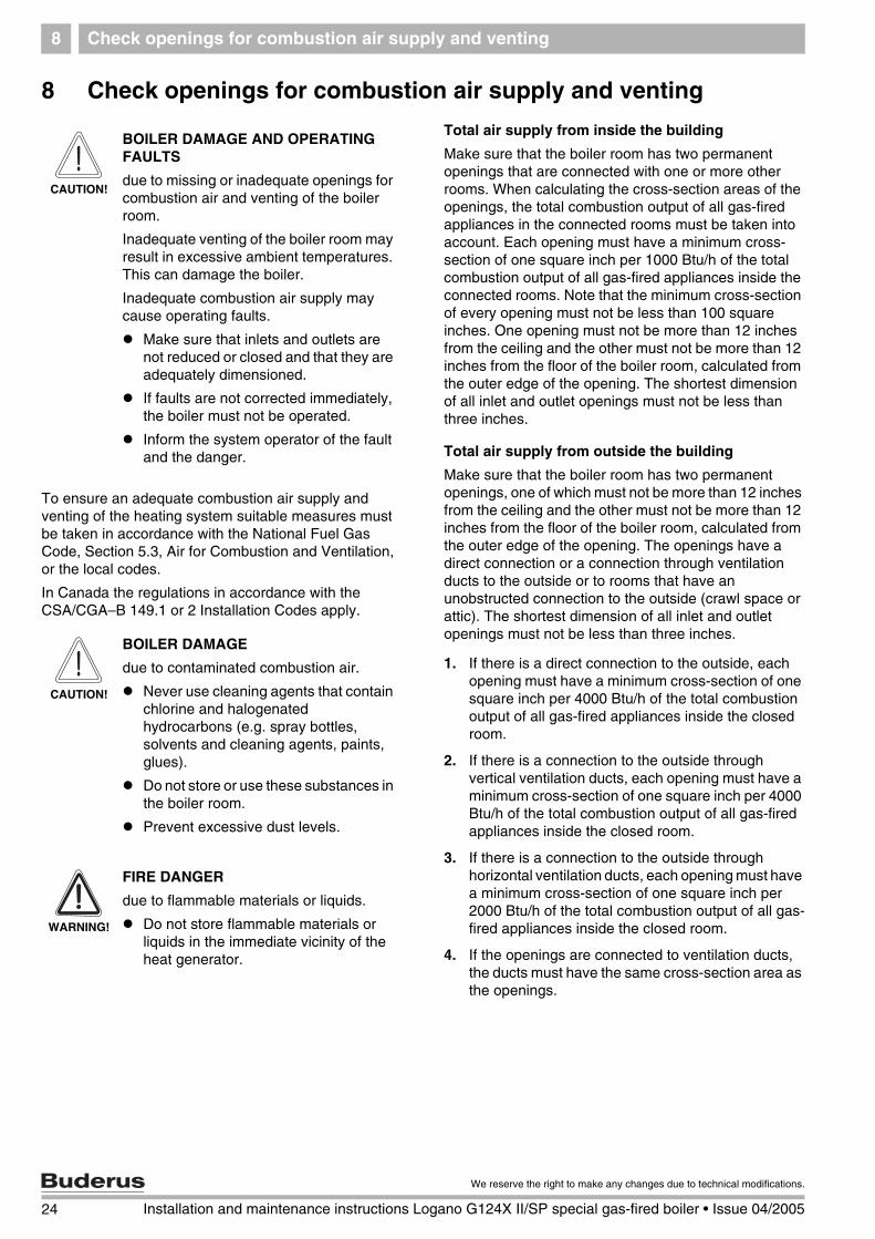
8 Check openings for combustion air supply and venting
To ensure an adequate combustion air supply and venting of the heating system suitable measures must be taken in accordance with the National Fuel Gas Code, Section 5.3, Air for Combustion and Ventilation, or the local codes.
In Canada the regulations in accordance with the CSA/CGA–B 149.1 or 2 Installation Codes apply.
Total air supply from inside the building
Make sure that the boiler room has two permanent openings that are connected with one or more other rooms. When calculating the cross-section areas of the openings, the total combustion output of all gas-fired appliances in the connected rooms must be taken into account. Each opening must have a minimum cross-section of one square inch per 1000 Btu/h of the total combustion output of all gas-fired appliances inside the connected rooms. Note that the minimum cross-section of every opening must not be less than 100 square inches. One opening must not be more than 12 inches from the ceiling and the other must not be more than 12 inches from the floor of the boiler room, calculated from the outer edge of the opening. The shortest dimension of all inlet and outlet openings must not be less than three inches.
Total air supply from outside the building
Make sure that the boiler room has two permanent openings, one of which must not be more than 12 inches from the ceiling and the other must not be more than 12 inches from the floor of the boiler room, calculated from the outer edge of the opening. The openings have a direct connection or a connection through ventilation ducts to the outside or to rooms that have an unobstructed connection to the outside (crawl space or attic). The shortest dimension of all inlet and outlet openings must not be less than three inches.
1. If there is a direct connection to the outside, each opening must have a minimum cross-section of one square inch per 4000 Btu/h of the total combustion output of all gas-fired appliances inside the closed room.
2. If there is a connection to the outside through vertical ventilation ducts, each opening must have a minimum cross-section of one square inch per 4000 Btu/h of the total combustion output of all gas-fired appliances inside the closed room.
3. If there is a connection to the outside through horizontal ventilation ducts, each opening must have a minimum cross-section of one square inch per 2000 Btu/h of the total combustion output of all gas-fired appliances inside the closed room.
4. If the openings are connected to ventilation ducts, the ducts must have the same cross-section area as the openings.
CAUTION!
BOILER DAMAGE AND OPERATING FAULTS
due to missing or inadequate openings for combustion air and venting of the boiler room.
Inadequate venting of the boiler room may result in excessive ambient temperatures. This can damage the boiler.
Inadequate combustion air supply may cause operating faults.
Make sure that inlets and outlets are not reduced or closed and that they are adequately dimensioned.
If faults are not corrected immediately, the boiler must not be operated.
Inform the system operator of the fault and the danger.
CAUTION!
BOILER DAMAGE
due to contaminated combustion air.
Never use cleaning agents that contain chlorine and halogenated hydrocarbons (e.g. spray bottles, solvents and cleaning agents, paints, glues).
Do not store or use these substances in the boiler room.
Prevent excessive dust levels.
WARNING!
FIRE DANGER
due to flammable materials or liquids.
Do not store flammable materials or liquids in the immediate vicinity of the heat generator.

Requirements for connection to chimneys or venting systems 9
25
We reserve the right to make any changes due to technical modifications.
Installation and maintenance instructions Logano G124X II/SP special gas-fired boiler • Issue 04/2005
9 Requirements for connection to chimneys or venting systems
The flue connection must comply with the regulations of the National Fuel Gas Code, Part 7, Venting of Equipment, and the local construction codes. In Canada the regulations in accordance with the CSA/CGA–B 149.1 or 2 Installation Codes apply.
Flue connections of heating systems with natural venting must not be connected with any component of a mechanically operated venting system that operates with overpressure.
The cross-section of the flue connection must not be less than that specified in the table.
If the boiler is to be connected to a brick chimney, the chnimney must be thoroughly inspected before use. The chimney must be clean, in compliance with construction codes and of sufficient dimensions.
Chimnneys with an internal liner are preferred and are only permitted if the liner complies with all national, state and local construction codes. Liners of fire-glazed brick with moisture-proof joints and liners of corrosion-resistant material are recommended. Contact the local gas supply company for advice and recommendations for flue connection and chimney liners. A flue pipe of single-walled sheet metal is required for flue connections for type II models.
An adequate chimney height in compliance with the tables of the National Fuel Gas Code, ANSI Z 223.1, is required.
Separation of a boiler from a common flue system
If an existing boiler is separated from a common venting system, the venting system will then be too large to guarantee correct venting for the heating systems that remain connected to the system.
Test the venting system by the following procedure:
Carry out these steps with every heating system that remains connected to the venting system when the boiler is separated from a common venting system. Every heating system must be started in operation and the other heating systems must remain switched off.
A All unused openings of the common system must be sealed.
B Inspect the venting system to ensure that it has the correct dimensions and longitudinal inclination. Make sure that the system is not blocked, leaking, corroded or has any other faults that cause it to operate improperly.
C If necessary, close all doors and windows in the building and all doors between the space in which the heating systems that remain connected to the venting system are installed and the other rooms of the building. Switch off washing machines and dryers and all appliances that are not connected to the venting system. Run all venting fans
and bathroom exhaust fans at maximum speed. Fans in use in summer must remain in operation and oven exhaust system flaps must be closed.
D Now start the heating system that is to be tested. Follow the instructions for starting. Set the thermostat for continuous operation.
E After the main gas burner has been operating for five minutes, check the opening at the back flow check for drafts with a match flame or a candle, or with the smoke of a cigarette, cigar or pipe.
F When all heating systems that remain connected to the venting system have been checked as above to ensure that the venting operates properly, return all doors, windows, exhaust fans, oven exhaust flaps and all other gas-fired appliances to their original position.
G Any incorrect status of the common venting system must be corrected to ensure that the heating system complies with the regulations of the National Fuel Gas Code, ANSI Z 223.1. If the size of any component of the common venting system is changed, the complete venting system must be resized to comply with the relevant tables in Part 11 of the National Fuel Gas Code, ANSI Z 223.1. In Canada the regulations in accordance with the CSA/CGA–B 149.1 or 2 Installation Codes apply.
Flue pipe installation10
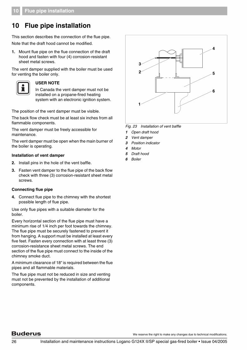
10 Flue pipe installation
This section describes the connection of the flue pipe.
Note that the draft hood cannot be modified.
1. Mount flue pipe on the flue connection of the draft hood and fasten with four (4) corrosion-resistant sheet metal screws.
The vent damper supplied with the boiler must be used for venting the boiler only.
The position of the vent damper must be visible.
The back flow check must be at least six inches from all flammable components.
The vent damper must be freely accessible for maintenance.
The vent damper must be open when the main burner of the boiler is operating.
Installation of vent damper
2. Install pins in the hole of the vent baffle.
3. Fasten vent damper to the flue pipe of the back flow check with three (3) corrosion-resistant sheet metal screws.
Connecting flue pipe
4. Connect flue pipe to the chimney with the shortest possible length of flue pipe.
Use only flue pipes with a suitable diameter for the boiler.
Every horizontal section of the flue pipe must have a minimum rise of 1/4 inch per foot towards the chimney. The flue pipe must be securely fastened to prevent it from hanging. A support must be installed at least every five feet. Fasten every connection with at least three (3) corrosion-resistance sheet metal screws. The end section of the flue pipe must connect to the inside of the chimney smoke duct.
A minimum clearance of 18“ is required between the flue pipes and all flammable materials.
The flue pipe must not be reduced in size and venting must not be prevented by the installation of additional components.
Fig. 23 Installation of vent baffle
1 Open draft hood2 Vent damper
3 Position indicator
4 Motor5 Draft hood
6 Boiler
4
5
6
3
2
1
USER NOTE
In Canada the vent damper must not be installed on a propane-fired heating system with an electronic ignition system.
26 Installation and maintenance instructions Logano G124X II/SP special gas-fired boiler • Issue 04/2005
We reserve the right to make any changes due to technical modifications.

Flue pipe installation 10
Installing electrical connection of vent damper
5. Disconnect your heating system from the mains electricity supply.
6. Route the connection wiring of the vent baffle through the wiring retainer behind the boiler and between the insulation and the jacket to the aquastat on the front of the boiler.
7. Connect vent damper to the terminal plug on aquastat as shown in the circuit diagram.
Fig. 24 Connecting vent damper (G124X II left, G124X SP right)
1 Terminal plug on aquastat
2 Aquastat
1 2 1 2
USER NOTE
All connection points on the complete venting system must be checked for correct installation and sealing immediately after carrying out one of the installation steps. The seams and connections must be checked for gas leaks. Regulations require the complete flue system to be checked at least once a year by a qualified technician after installation and initial operation.
27
We reserve the right to make any changes due to technical modifications.
Installation and maintenance instructions Logano G124X II/SP special gas-fired boiler • Issue 04/2005

Placing the heating system in operation11
11 Placing the heating system in operation
The burner and gas fittings unit integrated in the boiler have been tested in the factory as described in detail in ANSI Z 21.13 and CGA 4.9 to ensure safe operation of the heating system and to test specific performance indicators.
1. Set the room thermostats to the lowest setting.
2. Inspect flue and combustion air piping and the openings for combustion air supply and ventilation.
3. Fill heating system with water and bleed the complete system including the radiators.
4. Unscrew left and right screws in the side panels, lift front panel up, pull down and remove to the front.
WARNING!
RISK TO LIFE
due to electrical current when the unit is open.
Before opening the unit: To prevent electrical shock, isolate the heating system with the heating system emergency stop switch or by shutting off the main fuse.
Lock the heating system to prevent accidental reactivation.
Fig. 25 Removing front panel of boiler
1
2
28 Installation and maintenance instructions Logano G124X II/SP special gas-fired boiler • Issue 04/2005
We reserve the right to make any changes due to technical modifications.
Placing the heating system in operation 11
Carrying out leak test
5. Open gas shut-off in the gas line.
6. Check the gas connection line to the gas valve for leaks with soap solution. If no leaks are found, continue with step 8. If any leaks are found, close gas valve.
7. Seal leaks and repeat step 6.
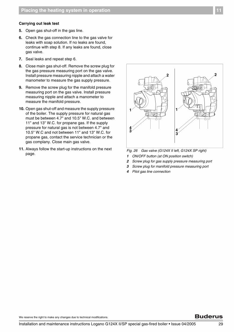
8. Close main gas shut-off. Remove the screw plug for the gas pressure measuring port on the gas valve. Install pressure measuring nipple and attach a water manometer to measure the gas supply pressure.
9. Remove the screw plug for the manifold pressure measuring port on the gas valve. Install pressure measuring nipple and attach a manometer to measure the manifold pressure.
10. Open gas shut-off and measure the supply pressure of the boiler. The supply pressure for natural gas must be between 4.7" and 10.5" W.C. and between 11" and 13" W.C. for propane gas. If the supply pressure for natural gas is not between 4.7" and 10.5" W.C and not between 11" and 13" W.C. for propane gas, contact the service technician or the gas complany. Close main gas valve.
11. Always follow the start-up instructions on the next page.
Fig. 26 Gas valve (G124X II left, G124X SP right)
1 ON/OFF button (at ON position switch)2 Screw plug for gas supply pressure measuring port
3 Screw plug for manifold pressure measuring port
4 Pilot gas line connection
1
2
34
1
2
34
29
We reserve the right to make any changes due to technical modifications.
Installation and maintenance instructions Logano G124X II/SP special gas-fired boiler • Issue 04/2005

Placing the heating system in operation11
11.1 Start-up instructions
Read the instructions before start-up for your safety.
A G124X II only: This unit is fitted with an ignition module that automatically starts the burner. Do not attempt to ignite it manually. G124X SP only: This unit is fitted with a burner that must be ignited manually. Follow the instructions below to ignite the burner.
B Check for an odor of gas around the heating system. This test must also be conducted at floor level, because some types of gas are heavier than air and may accumulate at floor level.
C Switch on the ON/OFF switch on the gas valve by hand only. Never use a tool as assistance. If you cannot actuate the ON/OFF switch on the gas valve by hand, do not attempt to repair it. Contact a qualified technician. Any attempt to use force or to repair the switch may cause a fire or explosion.
D Do not operate the unit if any part is under water. Contact a qualified customer service technician immediately to have the unit checked and to replace the parts of the control and gas valve that were under water.
WARNING!
RISK TO LIFE
due to not observing the start-up instructions and resulting incorrect operation.
If these instructions are not followed exactly, a fire or explosion may be caused with serious property damage or loss of life or serious injury.
Observe the installation instructions.
WARNING!
DANGER OF EXPLOSION
If you smell gas there is a danger of explosion.
No open flame. No smoking.
Prevent spark formation. Do not operate electrical switches, including telephones, plugs or door bells.
Close main gas valve.
Open doors and windows.
Warn other occupants of the building.
Evacuate the building.
Call gas company, heating service company or fire department from outside the building.
30 Installation and maintenance instructions Logano G124X II/SP special gas-fired boiler • Issue 04/2005
We reserve the right to make any changes due to technical modifications.
Placing the heating system in operation 11
11.2 Making G124X II and G124X SP boilers ready for operation
STOP! First read the safety instructions on page 8 of this manual.
1. Carry out leak test ( page 7). Wait five (5) minutes until all gas residues have dissipated. Finally check whether there is any smell of gas, including at floor level. If there is a gas odor: STOP! Follow instructions in section "B" of the safety instructions on page 28 of this manual. If there is no sign of a gas odor, continue with the next step.
2. Open main gas shut-off.
11.2.1 Placing heating system with aquastat control in operation
The boiler is fully functional with the factory-installed aquastat.
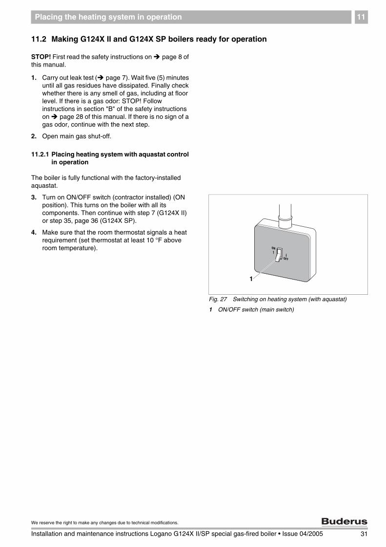
3. Turn on ON/OFF switch (contractor installed) (ON position). This turns on the boiler with all its components. Then continue with step 7 (G124X II) or step 35, page 36 (G124X SP).
4. Make sure that the room thermostat signals a heat requirement (set thermostat at least 10 °F above room temperature).
Fig. 27 Switching on heating system (with aquastat)
1 ON/OFF switch (main switch)
1
31
We reserve the right to make any changes due to technical modifications.
Installation and maintenance instructions Logano G124X II/SP special gas-fired boiler • Issue 04/2005

Placing the heating system in operation11
11.2.2 Placing heating system with Logamatic 2107 (accessory) in operation
The boiler is fully functional with the factory-installed aquastat. The Logamatic 2107 control can also be installed in addition to the factory-installed aquastat.
Turn on the heating system with the ON/OFF switch on the control. The burner starts operating if heat is required ( observe control service manual).
5. Make sure that heat is required at the control. Select "Manual operation" (hand symbol) with the mode selector switch.
6. Turn on ON/OFF switch ("I" position). Then continue with step 7 (G124X II) or step 35, page 36 (G124X SP).
11.3 Conducting final commissioning for G124X II boiler
The final commissioning for the G124X SP boiler is described in ( Chapter 11.4, page 36).
The following start-up procedures must be carried out regardless of the control type.
7. Look at the pilot burner through the sight glass in the burner housing.
Fig. 28 Turning on heating system (with Logamatic 2107 control)
1 Mode selection switch
2 ON/OFF switch
21
USER NOTE
After carrying out the instructions for starting described below, the control must be set to "AUT" mode (automatic operation) with the mode selector.
Fig. 29 G124X II boiler
1 Sight glass
1
32 Installation and maintenance instructions Logano G124X II/SP special gas-fired boiler • Issue 04/2005
We reserve the right to make any changes due to technical modifications.

Placing the heating system in operation 11
8. Turn gas valve ON/OFF switch counterclockwise to ON position.
9. The ignition module must generate sparks towards the pilot burner. The pilot flame must appear and then ignite the main burner. If the main burner does not ignite, close the gas shut-off. Disconnect heating system from the power supply and inform your customer service technician or LP gas company.
10. If the main burner has ignited, the gas valve must be checked for leaks with soap solution. If no leaks are found, continue with step 12. If leaks have been found, switch ON/OFF switch on gas valve clockwise to the OFF position. Disconnect heating system from the power supply and set the thermostat to the lowest setting.
11. Seal leaks. Repeat steps 1 and 2 (regardless of the control in use). Caution: With aquastat control continue with steps 3 and 4, with the Logamatic 2107 continue with steps 5 and 6. Then repeat steps 7 to 10 regardless of the control in use.
12. Check the supply gas pressure while the boiler is operating. The supply pressure must be between 4.7" and 10.5" W.C. for natural gas and between 11" and 13" W.C. for propane gas. Record the measured values in the commissioning protocol in the installation and maintenance instructions.
12b.Shut-off main gas supply. Install manometer on manifold to measure manifold pressure. Open shut-off valve, turn on boiler an measure manifold pressure.
13. Check manifold pressure. The manifold pressure must be set in accordance with the values in
Tab. 7. To set the manifold pressure the cover ( Fig. 30) on the gas valve must be removed. Turn the adjustment screw clockwise to increase the pressure and counterclockwise to reduce the pressure. This setting must be adjusted while the boiler is operating.
14. Record the set value in the commissioning protocol of the installation and maintenance instructions and screw the safety screw ( Fig. 30, page 33) into the gas valve again.
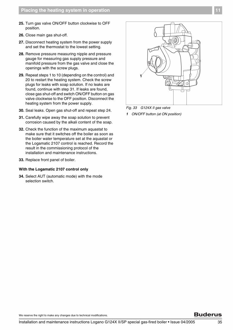
Fig. 30 G124X II gas valve
1 ON/OFF button (at ON position)
2 Screw plug for gas supply pressure measuring port
3 Safety screw for manifold pressure setting
4 Screw plug for manifold measuring port
5 Safety screw for pilot ignition pressure setting
1
2
45
3
G124X IINatural gas[inch W.C.]
Propane[inch W.C.]
18 3.6 9.8
25 3.5 10.3
32 3.6 10.0
Tab. 7 Manifold pressure
33
We reserve the right to make any changes due to technical modifications.
Installation and maintenance instructions Logano G124X II/SP special gas-fired boiler • Issue 04/2005

Placing the heating system in operation11
15. Observe pilot flame through the sight glass ( Fig. 29, page 32) in the burner housing.
16. The flame must envelope the flame guard 1/2 to 1 1/2 inches. If this is the case continue with step 20.
17. If the pilot flame is too small or too large, the pressure for the pilot burner must be adjusted with the corresponding adjustment screw.
18. Remove safety screw for igniter orifice pressure setting ( Fig. 30, page 33). Turn the inner adjustment screw clockwise to reduce the pilot flame and counterclockwise to enlarge the pilot flame.
19. After adjustment tighten the pilot gas pressure adjustment safety screw ( Fig. 30, page 33) again.
20. Observe main burner flame through the sight glass ( Fig. 29, page 32) in the burner housing. The flame must have a steady and fixed contour and generally has a bluish color. If the main burner flame meets the requirements, proceed with step 21. If the main burner flame is too weak or is yellow or goes out, turn the ON/OFF switch ( Fig. 30, page 33) on the gas fitting clockwise to OFF. Close the gas valve and disconnect the heating system from the power supply and contact the customer service technician or the gas company.
Checking flame sensor
21. Test the safety switch by closing the gas shut-off. The main burner flame ( Fig. 32) and the ignition flame ( Fig. 31) are extinguished. After six (6) seconds at the most the main gas solenoid valve on the gas fitting must close with an audible noise.
22. After 90 seconds the ignition module must switch to lock status and stop generating sparks.
23. Disconnect the heating system from the power supply. Open main gas valve. Switch on unit power supply. A normal operating cycle must follow.
24. If the gas fitting operates correctly, proceed to step 25. If the gas fitting does not operate correctly, switch ON/OFF switch ( Fig. 33) on the gas fitting clockwise to the OFF position immediately. Close main gas shut-off. Disconnect heating system from the power supply and inform the customer service technician or LP gas company.
Fig. 31 Correct pilot flame setting
1 1/2 to 1 1/2 inches
2 Pilot flame
1
2USER NOTE
The adjustment screw is behind the pilot burner pressure adjustment safety screw ( Fig. 30, page 33).
Fig. 32 Main burner
1 Main burner flame
1
34 Installation and maintenance instructions Logano G124X II/SP special gas-fired boiler • Issue 04/2005
We reserve the right to make any changes due to technical modifications.
Placing the heating system in operation 11
25. Turn gas valve ON/OFF button clockwise to OFF position.
26. Close main gas shut-off.
27. Disconnect heating system from the power supply and set the thermostat to the lowest setting.
28. Remove pressure measuring nipple and pressure gauge for measuring gas supply pressure and manifold pressure from the gas valve and close the openings with the screw plugs.
29. Repeat steps 1 to 10 (depending on the control) and 20 to restart the heating system. Check the screw plugs for leaks with soap solution. If no leaks are found, continue with step 31. If leaks are found, close gas shut-off and switch ON/OFF button on gas valve clockwise to the OFF position. Disconnect the heating system from the power supply.
30. Seal leaks. Open gas shut-off and repeat step 24.
31. Carefully wipe away the soap solution to prevent corrosion caused by the alkali content of the soap.
32. Check the function of the maximum aquastat to make sure that it switches off the boiler as soon as the boiler water temperature set at the aquastat or the Logamatic 2107 control is reached. Record the result in the commissioning protocol of the installation and maintenance instructions.
33. Replace front panel of boiler.
With the Logamatic 2107 control only
34. Select AUT (automatic mode) with the mode selection switch.
Fig. 33 G124X II gas valve
1 ON/OFF button (at ON position)
1
35
We reserve the right to make any changes due to technical modifications.
Installation and maintenance instructions Logano G124X II/SP special gas-fired boiler • Issue 04/2005

Placing the heating system in operation11
11.4 Conducting final commissioning for G124X SP boiler
The final commissioning for the G124X II boiler is described in ( Chapter 11.3, page 32).
The following start-up procedures must be carried out regardless of the control type.
35. Look at the igniter through the sight glass in the burner housing.
36. Turn gas valve ON/OFF switch counterclockwise to PILOT position.
37. Press reset button in completely and hold.
38. Ignite the pilot burner with the supplied match holder and a burning match through the sight glass in the burner housing.
39. When the pilot burner is burning, continue to hold the red reset button for about a minute.
40. Release red reset button. The red reset button must pop up and the pilot burner must continue burning. If the pilot burner goes out, switch ON/OFF switch on gas valve clockwise to OFF and repeat steps 1 and 2 (regardless of the control). Caution: With aquastat control continue with steps 3 and 4, with the Logamatic 2107 continue with steps 5 and 6. Then repeat steps 35 to 39 regardless of the control in use.
Fig. 34 G124X SP boiler
1 Sight glass
1
Fig. 35 G124X SP gas valve
1 Safety screw for pilot burner pressure setting
2 ON/OFF button (at ON position)
3 Reset button
4 Screw plug for gas supply pressure measuring port
5 Safety screw for manifold pressure setting
6 Screw plug for manifold measuring port
2
4
6
1
5
3
36 Installation and maintenance instructions Logano G124X II/SP special gas-fired boiler • Issue 04/2005
We reserve the right to make any changes due to technical modifications.

Placing the heating system in operation 11
41. Check pilot gas line for leaks with soap solution. If no leaks are found, continue with step 43. If leaks have been found, switch ON/OFF switch on gas valve ( Fig. 35, page 36) clockwise to the OFF position.
42. Seal leaks. Repeat steps 1 and 2 (regardless of the control in use). Caution: With aquastat control continue with steps 3 and 4, with the Logamatic 2107 continue with steps 5 and 6. Then repeat steps 35 to 41 regardless of the control in use.
43. Observe pilot flame through the sight glass ( Fig. 36) in the burner housing.
44. The pilot flame must surround the thermal element 3/8 to 1/2 inch. If this is the case continue with step 48.
45. If the pilot flame is too small or too large, the pressure for the pilot burner must be adjusted with the corresponding adjustment screw.
46. Remove safety screw for pilot burner pressure setting ( Fig. 37, page 38). Turn the inner adjustment screw clockwise to reduce the pilot flame and counterclockwise to enlarge the pilot flame.
WARNING!
RISK TO LIFE
due to poisoning by leaking gas.
If the red reset button does not pop up when you release it, STOP.
Close gas shut-off immediately to prevent gas from leaking.
Contact your service technician or LP gas supplier immediately and have the fault repaired.
If the pilot burner continues to go out after several attempts, turn the ON/OFF button on the gas valve to OFF immediately to prevent gas from leaking.
Fig. 36 Correct pilot flame setting
1 Pilot flame
2
1
USER NOTE
The adjustment screw is behind the pilot burner pressure adjustment safety screw ( Fig. 35, page 36).
37
We reserve the right to make any changes due to technical modifications.
Installation and maintenance instructions Logano G124X II/SP special gas-fired boiler • Issue 04/2005

Placing the heating system in operation11
47. After adjustment tighten the pilot burner pressure adjustment safety screw ( Fig. 37) again.
48. Turn gas valve ON/OFF switch ( Fig. 37) counterclockwise to ON position. The gas valve ON/OFF switch can only be set to ON if the red reset button is out.
49. Place the heating system electrically in operation
50. Make sure that the thermal element responds to heat.
51. The pilot flame must ignite the main burner. If the main burner does not ignite, close the gas valve. Disconnect heating system from the power supply and inform your customer service technician or LP gas company.
52. If the main burner has ignited, the gas valve must be checked for leaks with soap solution. If no leaks are found, continue with step 54. If leaks have been found, switch ON/OFF switch on gas valve ( Fig. 37) clockwise to the OFF position. Disconnect the heating system from the power supply.
53. Seal leaks. Repeat steps 35 to 52.
54. Check manifold pressure. The manifold pressure must be set in accordance with the values in
Tab. 8. To set the manifold pressure the safety screw for setting the manifold pressure on the gas valve must be removed. Turn the adjustment screw clockwise to increase the pressure and counterclockwise to reduce the pressure. This setting must be adjusted while the boiler is operating.
55. Record the set value in the commissioning protocol of the installation and maintenance instructions and screw the safety screw into the gas valve again.
Fig. 37 G124X SP gas valve
1 Safety screw for pilot burner pressure setting
2 ON/OFF button (at ON position)
3 Reset button
4 Screw plug for gas supply pressure measuring port
5 Safety screw for manifold pressure setting
6 Screw plug for manifold measuring port
2
4
6
1
5
3
G124X SPNatural gas[inch W.C.]
Propane[inch W.C.]
18 3.6 9.8
25 3.5 10.3
32 3.6 10.0
Tab. 8 Manifold pressure
38 Installation and maintenance instructions Logano G124X II/SP special gas-fired boiler • Issue 04/2005
We reserve the right to make any changes due to technical modifications.

Placing the heating system in operation 11
Check flame sensor
56. Turn gas valve ON/OFF button ( Fig. 37) clockwise to OFF position. The main burner flame and the pilot flame are extinguished.
57. Turn gas valve ON/OFF switch ( Fig. 38) counterclockwise to PILOT position.
58. Wait three (3) minutes and turn gas valve ON/OFF switch ( Fig. 38) counterclockwise to ON position. Gas must not flow into the main burner.
59. Use a pressure gauge to check that the manifold pressure (output pressure) is 0.
60. If gas flows turn gas valve ON/OFF switch ( Fig. 38) to OFF position immediately and close the gas shut-off.
61. Disconnect heating system from the power supply and inform your customer service technician or LP gas company. If no gas flows continue with step 62.
62. Turn gas valve ON/OFF button clockwise to OFF position.
63. Close main gas shut-off.
64. Disconnect the heating system from the power supply.
65. Remove pressure measuring nipple and pressure gauge for measuring gas supply pressure and manifold pressure from the gas valve and close the openings with the screw plugs.
66. Repeat steps 1 to 6 and 35 to 52 to place the heating system in operation again. Check the screw plugs for leaks with soap solution. If no leaks are found, continue with step 68. If leaks are found, close gas shut-off and switch ON/OFF button on gas valve clockwise to the OFF position. Disconnect the heating system from the power supply.
67. Seal leaks. Open gas shut-off and repeat step 66.
68. Carefully wipe away the soap solution to prevent corrosion caused by the alkali content of the soap.
69. Replace front panel of boiler.
With the Logamatic 2107 control only
70. Select AUT (automatic mode) with the mode selection switch.
Fig. 38 G124X SP gas valve
1 ON/OFF button (at ON position)
1
39
We reserve the right to make any changes due to technical modifications.
Installation and maintenance instructions Logano G124X II/SP special gas-fired boiler • Issue 04/2005
Placing the heating system in operation11
11.5 Shutting off gas supply to boiler
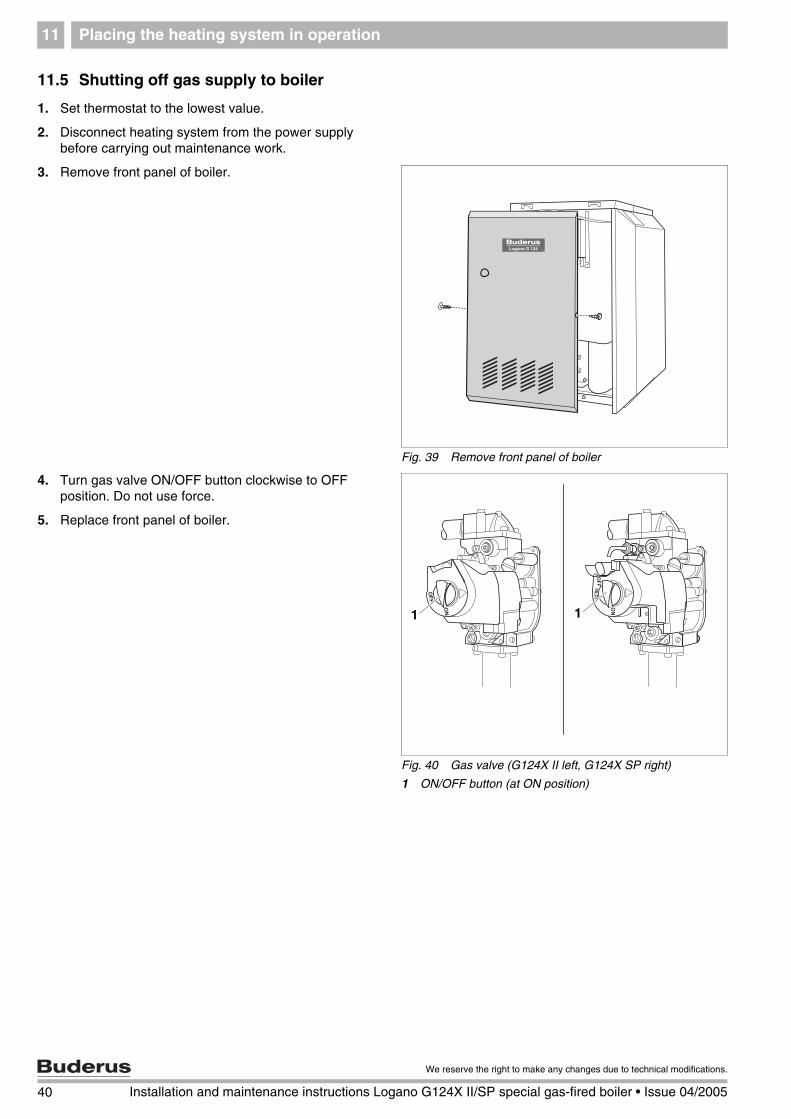
1. Set thermostat to the lowest value.
2. Disconnect heating system from the power supply before carrying out maintenance work.
3. Remove front panel of boiler.
4. Turn gas valve ON/OFF button clockwise to OFF position. Do not use force.
5. Replace front panel of boiler.
Fig. 39 Remove front panel of boiler
Fig. 40 Gas valve (G124X II left, G124X SP right)
1 ON/OFF button (at ON position)
1 1
40 Installation and maintenance instructions Logano G124X II/SP special gas-fired boiler • Issue 04/2005
We reserve the right to make any changes due to technical modifications.

Placing the heating system in operation 11
11.6 Instruct owner/operator and hand over technical documentation
Inform the owner/operator of the operation of the complete heating system and the operating instructions for the boiler. Together with the owner sign the protocol on page 42 and hand over the technical documentation.
CAUTION!
SYSTEM DAMAGE
due to frost. The heating system may freeze in frosty weather if it is not switched on with the main switch or control.
Protect the heating system from freezing when there is a danger of frost.
If the main switch or control is switched off, drain the water from the boiler, the tank and the pipe of the heating system.
41
We reserve the right to make any changes due to technical modifications.
Installation and maintenance instructions Logano G124X II/SP special gas-fired boiler • Issue 04/2005

Placing the heating system in operation11
11.7 Start-up protocol
Please check off the start-up work as it is completed and record the measured values in the table.
Start-up work Remarks or measured values
1. Type of gas Natural gas Propane
2. Check combustion air, inlet and outlet openings and flue gas connection
3. Check the unit orifices (correct orfices? See Tab. 9 below) and convert gas type if necessary
4. Fill boiler with water and bleed complete heating system
5. Measure gas supply pressure (flow pressure) ––––––––––––––––––– inches W. C.
6. Measure manifold pressure and adjust if necessary ––––––––––––––––––– inches W. C.
7. Leak check in operating status, check ignition and main burner flame and correct functioning of the venting system
8. Check maximum aquastat
9. Install front boiler panel
10. Inform operator, hand over technical documentation
11. Installer
Operator:
Signature:__________________ Signature:__________________
Main orifice identificationBoiler size 18 25 32
Natural gas 265 250 250Propane gas 175 160 160
Tab. 9 Main gas orfice identification
USER NOTE
Inform the customer of the correct fuel and enter it in the table ( operating manual of boiler).
42 Installation and maintenance instructions Logano G124X II/SP special gas-fired boiler • Issue 04/2005
We reserve the right to make any changes due to technical modifications.

Taking the boiler out of operation 12
43
We reserve the right to make any changes due to technical modifications.
Installation and maintenance instructions Logano G124X II/SP special gas-fired boiler • Issue 04/2005
12 Taking the boiler out of operation
12.1 Normal boiler shut-down
1. With the aquastat: Switch off ON/OFF switch ("OFF" position). This shuts down the boiler with all components (e.g. burner).
2. Additional shut-down procedure follow the directions for the aquastat.
3. Logamatic 2107 control (accessory): Switch off ON/OFF switch on control ("0" position). This shuts down the boiler with all components (e.g. burner).
4. Shut off main fuel supply.
12.2 Emergency shut-down
Inform your customer of the procedure in case of emergency, such as a fire.
1. Never put yourself at risk. Your own safety must always take priority.
2. Shut off main fuel supply valve.
3. Shut down the heating system with the heater emergency switch or the corresponding circuit-breaker.
Fig. 41 Shutting down heating system (with aquastat)
1 ON/OFF switch (main switch)
1
Fig. 42 Shutting down heating system (with Logamatic 2107 control)
1 ON/OFF switch
� �
1CAUTION!
SYSTEM DAMAGE
through frost.
The heating system can freeze up in cold weather if it is shut down.
Leave the heating system switched ON constantly as much as possible.
Protect the heating system from freezing by draining the heater and water pipes at the lowest point.
Boiler inspection and maintenance13
13 Boiler inspection and maintenance
13.1 Why is regular maintenance important?
Heating systems require regular maintenance for the following reasons:
– To maintain high efficiency operation and to operate the heating system economically (low fuel consumption).
– To sustain safe operation.
– To maintain combustion at an environmentally friendly level.
All maintenance work must be carried out by a qualified service technician only. When replacing components use only parts approved by Buderus. Maintenance is required once a year. Record the results of the inspection in the protocol at page 53.
13.2 Testing the flue system, including combustion air, air inlets and ventilation openings
Check the venting system, including the combustion air, inlet and outlet openings. All faults must be repaired immediately. Make sure that the combustion air feed and the inlets and outlets are not blocked at any point.
13.3 Inspection of the boiler and burner
1. Visually check the boiler and burner for external dirt.
2. If dirt is found, clean boiler and burner.
13.4 Preparing boiler for cleaning
1. Take the boiler out of operation ( Chapter 12.1, page 43).
2. Remove front panel of boiler ( Fig. 25, page 28).
USER NOTE
Spare parts can be ordered from the spare parts catalog.
WARNING!
RISK TO LIFE
from electric shock.
Before opening a unit: disconnect electrical power completely and lock to prevent accidental reconnection.
WARNING!
RISK TO LIFE
from explosion of flammable gases.
Never work on gas lines unless you are certified or licensed for this type of work.
44 Installation and maintenance instructions Logano G124X II/SP special gas-fired boiler • Issue 04/2005
We reserve the right to make any changes due to technical modifications.
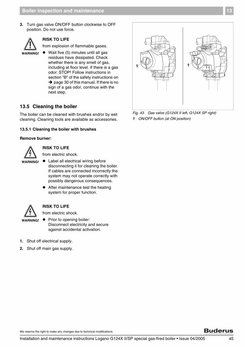
Boiler inspection and maintenance 13
3. Turn gas valve ON/OFF button clockwise to OFF position. Do not use force.
13.5 Cleaning the boiler
The boiler can be cleaned with brushes and/or by wet cleaning. Cleaning tools are available as accessories.
13.5.1 Cleaning the boiler with brushes
Remove burner:
1. Shut off electrical supply.
2. Shut off main gas supply.
Fig. 43 Gas valve (G124X II left, G124X SP right)
1 ON/OFF button (at ON position)
1 1
WARNING!
RISK TO LIFE
from explosion of flammable gases.
Wait five (5) minutes until all gas residues have dissipated. Check whether there is any smell of gas, including at floor level. If there is a gas odor: STOP! Follow instructions in section "B" of the safety instructions on
page 30 of this manual. If there is no sign of a gas odor, continue with the next step.
WARNING!
RISK TO LIFE
from electric shock.
Label all electrical wiring before disconnecting it for cleaning the boiler. If cables are connected incorrectly the system may not operate correctly with possibly dangerous consequences.
After maintenance test the heating system for proper function.
WARNING!
RISK TO LIFE
from electric shock.
Prior to opening boiler: Disconnect electricity and secure against accidental activation.
45
We reserve the right to make any changes due to technical modifications.
Installation and maintenance instructions Logano G124X II/SP special gas-fired boiler • Issue 04/2005
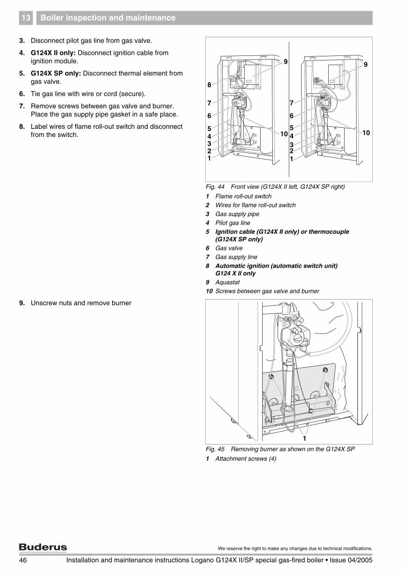
Boiler inspection and maintenance13
3. Disconnect pilot gas line from gas valve.
4. G124X II only: Disconnect ignition cable from ignition module.
5. G124X SP only: Disconnect thermal element from gas valve.
6. Tie gas line with wire or cord (secure).
7. Remove screws between gas valve and burner. Place the gas supply pipe gasket in a safe place.
8. Label wires of flame roll-out switch and disconnect from the switch.
9. Unscrew nuts and remove burner
Fig. 44 Front view (G124X II left, G124X SP right)
1 Flame roll-out switch2 Wires for flame roll-out switch
3 Gas supply pipe
4 Pilot gas line5 Ignition cable (G124X II only) or thermocouple
(G124X SP only)6 Gas valve
7 Gas supply line
8 Automatic ignition (automatic switch unit) G124 X II only
9 Aquastat10 Screws between gas valve and burner
1
43
5
8
6
9
2
7
10
1234
6
7
9
105
Fig. 45 Removing burner as shown on the G124X SP
1 Attachment screws (4)
1
46 Installation and maintenance instructions Logano G124X II/SP special gas-fired boiler • Issue 04/2005
We reserve the right to make any changes due to technical modifications.

Boiler inspection and maintenance 13
10. Remove boiler jacket.
11. Fold insulation to the side.
12. Unscrew cleaning cover from the venting manifold.
13. Cover control with foil to prevent entry of metal dust into the control.
14. Use boiler brush to clean out flue gas passages.
15. Clean combustion chamber and bottom insulation.
16. Screw cleaning cover into place and replace insulation.
13.5.2 Wet cleaning (chemical cleaning)
For the wet cleaning use a suitable cleaning agent for the degree of build-up of dirt (soot or scale).
Use the same procedure as described for cleaning with brushes ( Chapter 13.5.1, page 45).
17. Cover control with foil to prevent entry of spray into the control.
18. Ventilate boiler room well.
19. Spray flue gas vents evenly with the cleaning agent.
20. Replace and install the burner in reverse order of removal and disassembly ( page 45).
21. Place the heating system in operation.
22. Heat the boiler water to a temperature of at least 122 °F.
23. Take the boiler out of operation.
24. Allow boiler to cool.
25. Remove burner ( page 45).
26. Brush out flue gas passages.
27. Clean combustion chamber and bottom insulation.
28. Ventilate boiler room well again.
29. Install burner.
30. Attach boiler jacket.
Fig. 46 Cleaning the hot flue passages
1 Cleaning brush
2 Insulation
1 2
3
2
12
USER NOTE
Observe the directions for use of the cleaning agent. In some case you may need use a different procedure from that described here.
Fig. 47 Wet-cleaning the boiler
47
We reserve the right to make any changes due to technical modifications.
Installation and maintenance instructions Logano G124X II/SP special gas-fired boiler • Issue 04/2005
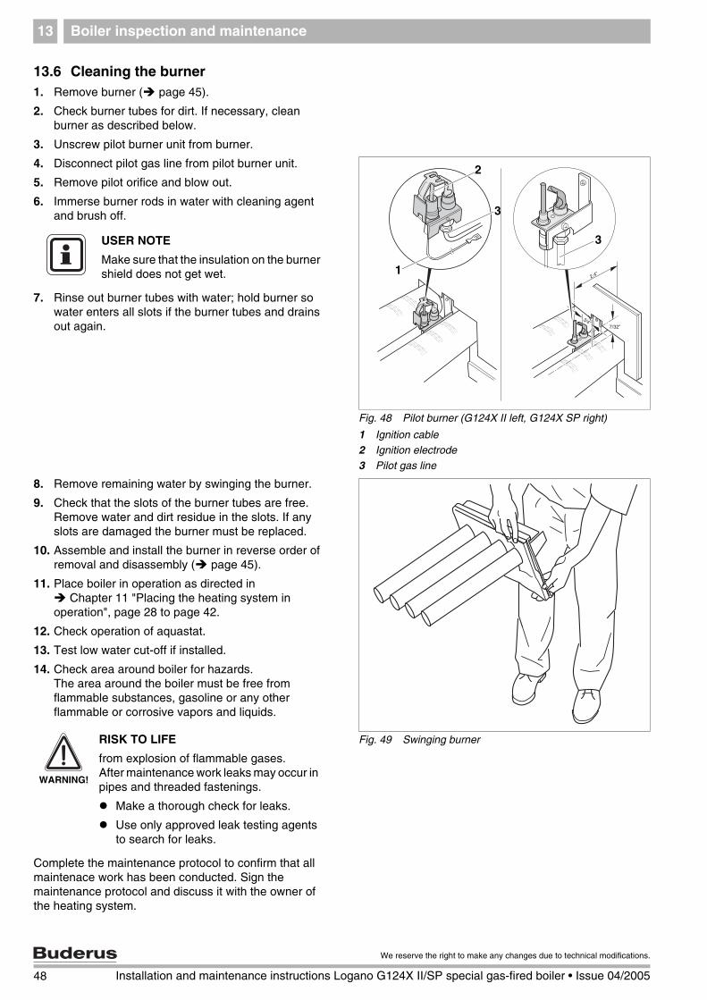
Boiler inspection and maintenance13
13.6 Cleaning the burner1. Remove burner ( page 45).
2. Check burner tubes for dirt. If necessary, clean burner as described below.
3. Unscrew pilot burner unit from burner.
4. Disconnect pilot gas line from pilot burner unit.
5. Remove pilot orifice and blow out.
6. Immerse burner rods in water with cleaning agent and brush off.
7. Rinse out burner tubes with water; hold burner so water enters all slots if the burner tubes and drains out again.
8. Remove remaining water by swinging the burner.
9. Check that the slots of the burner tubes are free. Remove water and dirt residue in the slots. If any slots are damaged the burner must be replaced.
10. Assemble and install the burner in reverse order of removal and disassembly ( page 45).
11. Place boiler in operation as directed in Chapter 11 "Placing the heating system in
operation", page 28 to page 42.
12. Check operation of aquastat.
13. Test low water cut-off if installed.
14. Check area around boiler for hazards. The area around the boiler must be free from flammable substances, gasoline or any other flammable or corrosive vapors and liquids.
Complete the maintenance protocol to confirm that all maintenace work has been conducted. Sign the maintenance protocol and discuss it with the owner of the heating system.
Fig. 48 Pilot burner (G124X II left, G124X SP right)
1 Ignition cable2 Ignition electrode
3 Pilot gas line
1
3
3
2
USER NOTE
Make sure that the insulation on the burner shield does not get wet.
Fig. 49 Swinging burner
WARNING!
RISK TO LIFE
from explosion of flammable gases. After maintenance work leaks may occur in pipes and threaded fastenings.
Make a thorough check for leaks.
Use only approved leak testing agents to search for leaks.
48 Installation and maintenance instructions Logano G124X II/SP special gas-fired boiler • Issue 04/2005
We reserve the right to make any changes due to technical modifications.

Boiler inspection and maintenance 13
13.7 Troubleshooting on the G124X II
Equipment required: Wiring diagrams ( Chapter 16, page 74) and voltage detectors for 120 VAC and 24 VAC.
Start
Close gas valve. Set thermostat (control) to require heat (flue baffle open).Switch on power.
Observe ignition sparks in gap between electrode and sensor through sight glass.
• Check electrical power supply, low-voltage transformer, thermostat (control) and wiring. Check that the Vent Damper (if installed) is open and the limit switch is present.
No
No
NoOpen main gas valve. Ignition flame is burning.
• Check that all manually operated vent dampers are open; check that gas connections and pressures are correct and that main orifices are not blocked.
• Check electrical connection between ignition module and connection on the gas valve.
• Use MV-MV/PV terminals to check 24 V alternating current at the automatic ignition. If the voltage is correct replace gas valve, otherwise replace automatic ignition.
NoSystem operates until the heat requirement ends.
• Check ignition wiring and ground for continuity. Note: If the ground is weak or faulty, the system may switch off at random, even if the heating system operates correctly when checked.
• Check that the ignition flame surrounds the electrode and burns evenly with a bluish flame. If OK replace pilot assembly.
• If everything is OK replace ignition module.
NoHeat requirement ended, system switches off, vent damper closes.
End of troubleshooting Repeat procedure until heating system operates correctly.
• On models with vent damper check that it operates and Limit switches are present. If necessary, replace vent damper.
• Check ignition wiring, ceramic insulator of ignition electrode and ignition gap, adjust if necessary.
• Check the ignition cable contact for signs of scorching or kinking.
• Replace ignition control unit.
NoIgnition spark stops as soon as ignition flame burns.
• Check ignition wiring and ground for continuity.
• Check ignition electrode.
• Check electrical connections between ignition electrode and ignition module.
• Check whether the ceramic insulator in the ignition electrode is broken.
• Check that the ignition flame surrounds the electrode and burns steadily with a bluish flame.
• Adjust pilot flame.
• If this does not correct the fault, replace the ignition module.
NoMain burner ignites.
• Use MV-MV/PV terminals to check 24 V alternating current, closed current circuit at the automatic ignition. If there is no voltage, replace ignition control.
• Check electrical connection between ignition module and gas valve. If OK, replace gas valve.
• Check operation of thermostat (control).
• Disconnect 24-V connection to gas valve. If gas valve closes, check thermostat and connection line again.
• If the gas valve does not close, replace gas valve.
49
We reserve the right to make any changes due to technical modifications.
Installation and maintenance instructions Logano G124X II/SP special gas-fired boiler • Issue 04/2005

Boiler inspection and maintenance13
STARTRoom thermostat (control) signals heat requirement
Vent Damper (if installed) opens.
Ignition spark generator operates• ignition gas valve opens.
With steady pilot flame• ignition spark generator stops. • main gas solenoid valve opens.
Main burner operation• ignition module monitors pilot flame.
Specified thermostat value (control) reachedMain and ignition gas valves close, gas burners extinguished, Vent Damper (if installed) closes.
Pilot burner operationPilot flame burns, ignition module
signals steady pilot flame.or ignition flame does not burn,
ignition module starts ignition attempt,
switches off after 90 seconds.
END
PHASE 1
Ignition attempt
PHASE 2
Main burneroperating
Power interruptionSystem switches off. Does the system restart when power is restored?
Pilot flame faultMain gas valve closes,ignition module starts new ignition attempt.
50 Installation and maintenance instructions Logano G124X II/SP special gas-fired boiler • Issue 04/2005
We reserve the right to make any changes due to technical modifications.

Boiler inspection and maintenance 13
13.8 Troubleshooting on the G124X SP
Equipment required: Wiring diagrams ( Chapter 16, page 74) and voltage detectors for 120 VAC and 24 VAC.
• Check connections to gas fitting.
• If the ignition flame goes out, check that the thermal element is firmly screwed to the gas valves; if yes, replace thermal element.
• If the ignition flame continues to go out, replace gas valves.
• Check that all manually operated baffles are open; check that gas connections and pressures are correct and that ignition gas nozzles are not blocked.
• Check connections to gas valve.
• If the ignition flame goes out, check that the thermal element is firmly screwed to the gas valve; if yes, replace pilot assembly.
• If the ignition flame continues to go out, replace gas valves.
• Check that all manually operated baffles are open; check that gas connections and pressures are correct and that main orifices are not blocked.
Start
Set gas valve ON/OFF button clockwise to OFF position. Close main gas valve. Set thermostat (control) to heat requirement (vent damper opens).Switch on power.
Set gas valve ON/OFF button counterclockwise to PILOT position. Open main gas valve. Press red reset button and ignite ignition flame. Hold down red reset button for one minute and then release. Ignition flame is burning.
• Check electrical power supply, low-voltage transformer, thermostat (control) and wiring. Check that the vent damper (if installed) is open and the limit switch is present.
No
No
NoSet gas valve ON/OFF button counterclockwise to ON. Main burner ignites.
• Check 24-V voltage at the gas valve.
• Check electrical connections to gas valve. If OK replace gas valve.
NoSystem operates until the heat requirement ends.
• Check that the ignition flame surrounds the thermocouple and burns evenly with a bluish flame. If OK replace thermocouple.
NoHeat requirement ended, system switches off, vent damper closes. Ignition flame continues to burn.
• Check operation of thermostat (control).
• Disconnect 24-V connection to gas fitting. If gas valve closes, check thermostat and connection line again.
• If the gas valve does not close, replace gas valve.
End of troubleshooting Repeat procedure until heating system operates correctly.
51
We reserve the right to make any changes due to technical modifications.
Installation and maintenance instructions Logano G124X II/SP special gas-fired boiler • Issue 04/2005
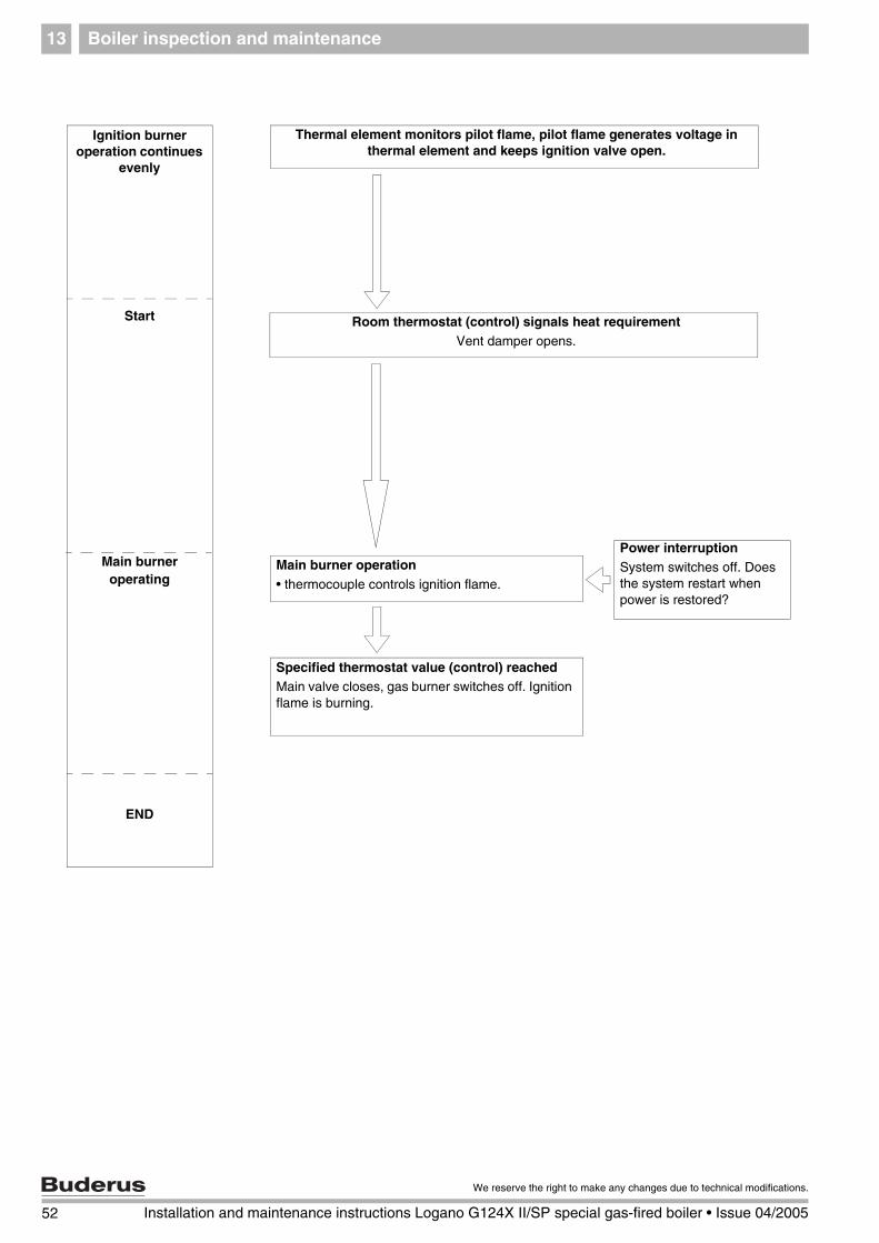
Boiler inspection and maintenance13
Ignition burner operation continues
evenly
Thermal element monitors pilot flame, pilot flame generates voltage in thermal element and keeps ignition valve open.
Main burner operation• thermocouple controls ignition flame.
Specified thermostat value (control) reachedMain valve closes, gas burner switches off. Ignition flame is burning.
END
Start
Main burneroperating
Power interruptionSystem switches off. Does the system restart when power is restored?
Room thermostat (control) signals heat requirementVent damper opens.
52 Installation and maintenance instructions Logano G124X II/SP special gas-fired boiler • Issue 04/2005
We reserve the right to make any changes due to technical modifications.

Boiler inspection and maintenance 13
13.9 Maintenance protocol
Please check off the maintenance work as it is completed and record the measured values. Follow the instructions on the following pages.
Maintenance work Page Date: Date:
1. Inspection of the flue system including combustion air, inlet and outlet openings
page 44
2. Inspection of boiler page 44
3. Inspection of burner page 44
4. Cleaning boiler page 45
5. Cleaning burner page 48
6. Measuring gas supply pressure page 29 –––––––inches W. C. –––––––inches W. C.
7 Measuring manifold pressure page 33/page 38 –––––––inches W. C. –––––––inches W. C.
8. Checking for leaks in operating condition page 29
9. Checking pilot and main burner flame page 34/page 37 ff.
10. Check maximum aquastat setting page 48
11. Check the area around the boiler for flammable materials, gasoline or other corrosive liquids.
page 48
12. Confirm maintenance
Confirmation of correct maintenance
(company stamp, signature)
53
We reserve the right to make any changes due to technical modifications.
Installation and maintenance instructions Logano G124X II/SP special gas-fired boiler • Issue 04/2005

Boiler inspection and maintenance13
Date: Date: Date: Date: Date:
–––––––inches W. C. –––––––inches W. C. –––––––inches W. C. –––––––inches W. C. –––––––inches W. C.
–––––––inches W. C. –––––––inches W. C. –––––––inches W. C. –––––––inches W. C. –––––––inches W. C.
54 Installation and maintenance instructions Logano G124X II/SP special gas-fired boiler • Issue 04/2005
We reserve the right to make any changes due to technical modifications.
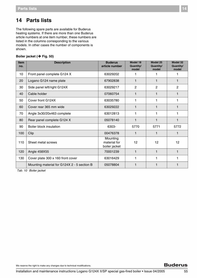
Parts lists 14
14 Parts lists
The following spare parts are available for Buderus heating systems. If there are more than one Buderus article numbers at one item number, these numbers are listed in the columns corresponding to the various models. In other cases the number of components is shown.
Boiler jacket ( Fig. 50)
Item no.
Description Buderus article number
Model 18Quantity/
model
Model 25Quantity/
model
Model 32Quantity/
model
10 Front panel complete G124 X 63029202 1 1 1
20 Logano G124 name plate 67902838 1 1 1
30 Side panel left/right G124X 63029217 2 2 2
40 Cable holder 07060754 1 1 1
50 Cover front G124X 63035780 1 1 1
60 Cover rear 365 mm wide 63029222 1 1 1
70 Angle 3x30/20x463 complete 63012813 1 1 1
80 Rear panel complete G124 X 05078140 1 1 1
90 Boiler block insulation 6303- 5770 5771 5772
100 Clip 00476378 1 1 1
110 Sheet metal screwsMounting
material for boiler jacket
12 12 12
120 Angle 458X55 70001239 1 1 1
130 Cover plate 300 x 160 front cover 63016429 1 1 1
Mounting material for G124X 2 - 5 section B 05078804 1 1 1
Tab. 10 Boiler jacket
55
We reserve the right to make any changes due to technical modifications.
Installation and maintenance instructions Logano G124X II/SP special gas-fired boiler • Issue 04/2005
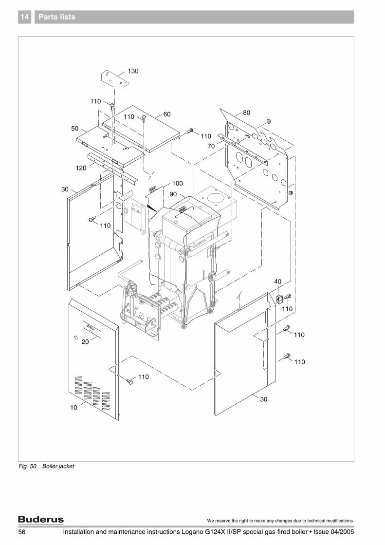
Parts lists14
Fig. 50 Boiler jacket
G 124 X
Buderus
110
90
120
60 80
100
70
20
10
50
30
110
110
110
110
110
40
110
30
110
130
56 Installation and maintenance instructions Logano G124X II/SP special gas-fired boiler • Issue 04/2005
We reserve the right to make any changes due to technical modifications.

Parts lists 14
Tab. 11 Boiler
Boiler block – attachment parts ( Fig. 51)Item no.
Description Buderus article number
Model 18Quantity/
model
Model 25Quantity/
model
Model 32Quantity/
model
10 Boiler block 08197- 252 254 256
11 Threaded stud M8x30see Mounting material boiler
block4 4 4
12 Hex head nut M8see Mounting material boiler
block5 5 5
13 Immersion well 05446065 1 11 1
14 Gasket 86159710 4 4 4
15 Plug 06073304 2 2 2
20 Boiler rail complete G124X 05078130 1 1 1
30 Boiler rail rear 63039580 1 1 1
50 Washersee Mounting material boiler
block2 2 2
60 Hex screw M8x16see Mounting material boiler
block4 4 4
70 Leveling legs M10x51mm 05871596 4 4 4
80 Insulation for base group 05078- 302 304 306
90 Spacer 05176794 4 4 4
100 Distance pin M8x63.5 00475485 1 1 1
110 Hex nut M10see Mounting material boiler
block2 2 2
120 Snap nut 4.8-SNU2012see Mounting material boiler
block4 4 4
130 Sheet metal screw ST4.8x22see Mounting material boiler
block2 2 2
140 Flue collar 05521- 240 240 242
150 Elbow 05407350 1 1 1
160 Back flow check 05181- 710 712 714
161 Cleaning cover 05371- 974 976 978
162 Sheet metal screw ST4.8x13see Mounting material boiler
block2 2 2
170 Elbow 05407352 1 1 1
180 Vent Damper 9990- 6864 6864 6865
200 B-kit G/GA124"US/CA" 63037069 1 1 1
Mounting material for boiler block G124X 05078806 1 1 1
57
We reserve the right to make any changes due to technical modifications.
Installation and maintenance instructions Logano G124X II/SP special gas-fired boiler • Issue 04/2005

Parts lists14
Fig. 51 Boiler block – attachment parts
180
162
130
160
161130
1410
120
140
15
14
1415
150200
12100 220
210
110
110
30 5060
120
170
70
14
80
70
5060
2090
12
12
13
11
58 Installation and maintenance instructions Logano G124X II/SP special gas-fired boiler • Issue 04/2005
We reserve the right to make any changes due to technical modifications.
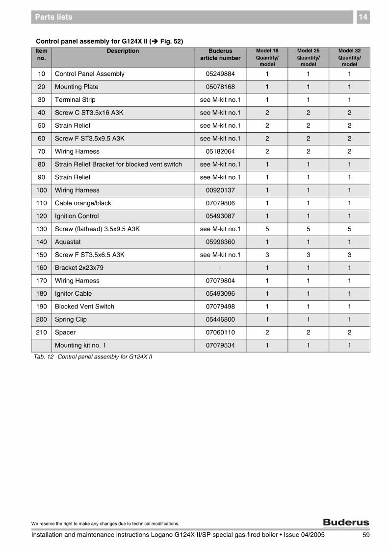
Parts lists 14
Control panel assembly for G124X II ( Fig. 52)Item no.
Description Buderus article number
Model 18Quantity/
model
Model 25Quantity/
model
Model 32Quantity/
model
10 Control Panel Assembly 05249884 1 1 1
20 Mounting Plate 05078168 1 1 1
30 Terminal Strip see M-kit no.1 1 1 1
40 Screw C ST3.5x16 A3K see M-kit no.1 2 2 2
50 Strain Relief see M-kit no.1 2 2 2
60 Screw F ST3.5x9.5 A3K see M-kit no.1 2 2 2
70 Wiring Harness 05182064 2 2 2
80 Strain Relief Bracket for blocked vent switch see M-kit no.1 1 1 1
90 Strain Relief see M-kit no.1 1 1 1
100 Wiring Harness 00920137 1 1 1
110 Cable orange/black 07079806 1 1 1
120 Ignition Control 05493087 1 1 1
130 Screw (flathead) 3.5x9.5 A3K see M-kit no.1 5 5 5
140 Aquastat 05996360 1 1 1
150 Screw F ST3.5x6.5 A3K see M-kit no.1 3 3 3
160 Bracket 2x23x79 - 1 1 1
170 Wiring Harness 07079804 1 1 1
180 Igniter Cable 05493096 1 1 1
190 Blocked Vent Switch 07079498 1 1 1
200 Spring Clip 05446800 1 1 1
210 Spacer 07060110 2 2 2
Mounting kit no. 1 07079534 1 1 1
Tab. 12 Control panel assembly for G124X II
59
We reserve the right to make any changes due to technical modifications.
Installation and maintenance instructions Logano G124X II/SP special gas-fired boiler • Issue 04/2005

Parts lists14
Fig. 52 Control panel assembly for G124X II
Honeywell
190
90
40
60
50
30
80
20
70
70
10
150
160
130
150
170
130
140
120110
180
100
200
210
210
60 Installation and maintenance instructions Logano G124X II/SP special gas-fired boiler • Issue 04/2005
We reserve the right to make any changes due to technical modifications.

Parts lists 14
Control panel assembly for G124X SP ( Fig. 53)Item no.
Description Buderus article number
Model 18Quantity/
model
Model 25Quantity/
model
Model 32Quantity/
model
10 Control Panel Assembly GAW 021 05249885 1 1 1
20 Mounting Plate 05078168 1 1 1
30 Terminal Strip see M-kit no.1 1 1 1
40 Screw C ST3.5x16 A3K see M-kit no.1 2 2 2
50 Strain Relief see M-kit no.1 2 2 2
60 Screw F ST3.5x9.5 A3K see M-kit no.1 2 2 2
70 Wiring Harness 05182064 2 2 2
80 Strain Relief Bracket for blocked vent switch see M-kit no.1 1 1 1
90 Strain Relief see M-kit no.1 1 1 1
100 Cable Harness 63015948 1 1 1
110 Aquastat 05996360 1 1 1
120 Screw F ST3.5x6.5 A3K see M-kit no.1 3 3 3
130 Screw (flathead) 3.5x9.5 A3K see M-kit no.1 3 3 3
140 Bracket 2x23x79 - 1 1 1
150 Blocked Vent Switch 07079498 1 1 1
160 Spring Clip 05446800 1 1 1
170 Spacer 07060110 2 2 2
Mounting kit no. 1 07079534 1 1 1
Tab. 13 Control panel assembly for G124X SP
61
We reserve the right to make any changes due to technical modifications.
Installation and maintenance instructions Logano G124X II/SP special gas-fired boiler • Issue 04/2005

Parts lists14
Fig. 53 Control panel assembly for G124X SP
Honeywell
80
150
70
70
12010
90
40
30
120
160
170
130
140100
50
60
110
20
62 Installation and maintenance instructions Logano G124X II/SP special gas-fired boiler • Issue 04/2005
We reserve the right to make any changes due to technical modifications.

Parts lists 14
Tab. 14 Manifold - component parts
Manifold - component parts ( Fig. 54)Item no.
Description Buderus article number
Model 18Quantity/
model
Model 25Quantity/
model
Model 32Quantity/
model
10 Bracket 70000- 463 464 465
20 Screw, M5x8-A3K see M-kit no. 2 4 4 4
30 Insulation including adhesive 05181396 1 1 1
31 Adhesive for insulation 02037312 1 1 1
40 Roll-out switch 00471336 1 1 1
50 Screw, M4x16-ST see M-kit no. 2 2 2 2
60 Manifold 05176- 979 980 981
61 Gasket for union 05959280 1 1 1
All orifices are for 0-8500 feet elevation. Contact Buderus Hydronic Systems for high altitude conversions
62 Gasket 05883094 2 3 4
70 Nozzle Kit NG-0-8500 ft 5484 408 400 396
80 Match Bracket (only for G124X SP) 05176863 1 1 1
Mounting kit no. 2 for G124X II: 05181 883 1 1 1
Mounting kit no. 2 for G124X SP 05176 996 1 1 1
90 Manifold Assembly NG 8500 ft. AE124X II 05272- 514 516 518
100 Manifold Assembly NG 8500 ft. AE124X SP 05272- 570 572 574
USER NOTE
The complete burner is supplied only in the model for natural gas G20 for 0-8500 feet. If a different model of burner is wanted, the corresponding gas conversion parts must be included in the order. The replaced parts must remain with the heating system for a possible future reconversion.
Gas type conversion partsItem no.
Description Buderus article number
Model 18Quantity/
model
Model 25Quantity/
model
Model 32Quantity/
model
NG kit G124X 0-8500 ft "US/CA" 6303- 8348 8349 8350
NG kit G124X 8501 - 12000 ft "US/CA" 6303- 7801 7802 7803
LP kit G124X II 0-8500 ft "US/CA" 6303- 7780 7781 7782
LP kit G124X II 8501 - 12000 ft "US/CA" 6303- 7783 7784 7785
LP kit G124X SP 0-8500 ft "US/CA" 6303- 7786 7788 7790
LP kit G124X SP 8501 - 12000 ft "US/CA" 6303- 7794 7797 7800
Tab. 15 Gas-type conversion parts for G124 X II and G124X SP
63
We reserve the right to make any changes due to technical modifications.
Installation and maintenance instructions Logano G124X II/SP special gas-fired boiler • Issue 04/2005

Parts lists14
Fig. 54 Manifold - component parts
10
10
80
3040
50
20
62
61
60
70
90100
A
A
31
64 Installation and maintenance instructions Logano G124X II/SP special gas-fired boiler • Issue 04/2005
We reserve the right to make any changes due to technical modifications.

Parts lists 14
Tab. 16 Gas union for G124X II
Gas union for G124X II ( Fig. 55)Item no.
Description Buderus article number
Model 18Quantity/
model
Model 25Quantity/
model
Model 32Quantity/
model
10 Gas Supply Pipe Assy 151 mm incl. O-ring 05176736 1 1 -
10 Gas Supply Pipe Assy 241 mm incl. O-ring 05176737 - - 1
20 Gas Control for Natural Gas 00475825 1 1 1
30 Gas Pipe for union 00905239 1 1 1
65
We reserve the right to make any changes due to technical modifications.
Installation and maintenance instructions Logano G124X II/SP special gas-fired boiler • Issue 04/2005
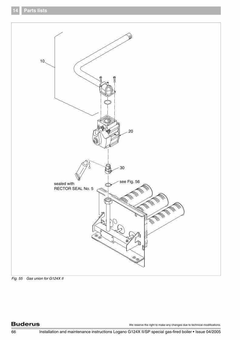
Parts lists14
Fig. 55 Gas union for G124X II
��
��
��������
��
���������������������������
66 Installation and maintenance instructions Logano G124X II/SP special gas-fired boiler • Issue 04/2005
We reserve the right to make any changes due to technical modifications.
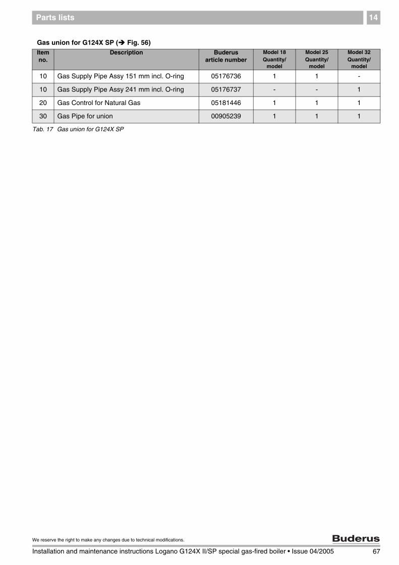
Parts lists 14
Gas union for G124X SP ( Fig. 56)Item no.
Description Buderus article number
Model 18Quantity/
model
Model 25Quantity/
model
Model 32Quantity/
model
10 Gas Supply Pipe Assy 151 mm incl. O-ring 05176736 1 1 -
10 Gas Supply Pipe Assy 241 mm incl. O-ring 05176737 - - 1
20 Gas Control for Natural Gas 05181446 1 1 1
30 Gas Pipe for union 00905239 1 1 1
Tab. 17 Gas union for G124X SP
67
We reserve the right to make any changes due to technical modifications.
Installation and maintenance instructions Logano G124X II/SP special gas-fired boiler • Issue 04/2005
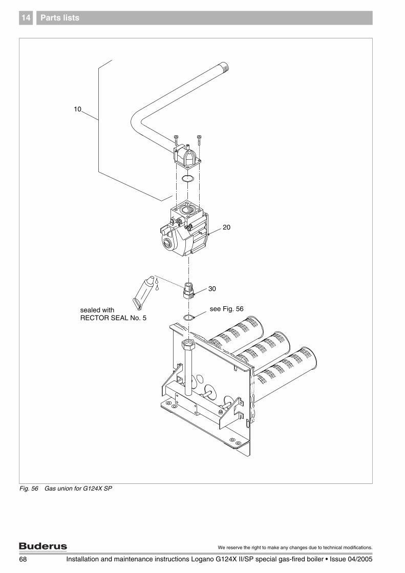
Parts lists14
Fig. 56 Gas union for G124X SP
��
��
�������� ���������������������������
��
68 Installation and maintenance instructions Logano G124X II/SP special gas-fired boiler • Issue 04/2005
We reserve the right to make any changes due to technical modifications.

Parts lists 14
Pilot burner for G124X II ( Fig. 57)Item no.
Description Buderus article number
Model 18Quantity/
model
Model 25Quantity/
model
Model 32Quantity/
model
10 Hex screw, 10x32x3/16-ST see M-kit no. 2 1 1 1
20 Pilot burner, Q3451E 05181443 1 1 1
30 Pilot orifice, natural gas, BCR20 05181648 1 1 1
30 Pilot orifice, propane gas, BCR12 05176998 1 1 1
40 Mounting for pilot line 05181672 1 1 1
50 Pilot bracket see M-kit no. 2 1 1 1
60 Pilot line 05181- 920 920 922
70 Screw, M5x8-A3K see M-kit no. 2 1 1 1
80 Screw, M4x12-A3K see M-kit no. 2 1 1 1
Mounting kit no. 2 05181883 1 1 1
Tab. 18 Pilot burner for G124X II
69
We reserve the right to make any changes due to technical modifications.
Installation and maintenance instructions Logano G124X II/SP special gas-fired boiler • Issue 04/2005
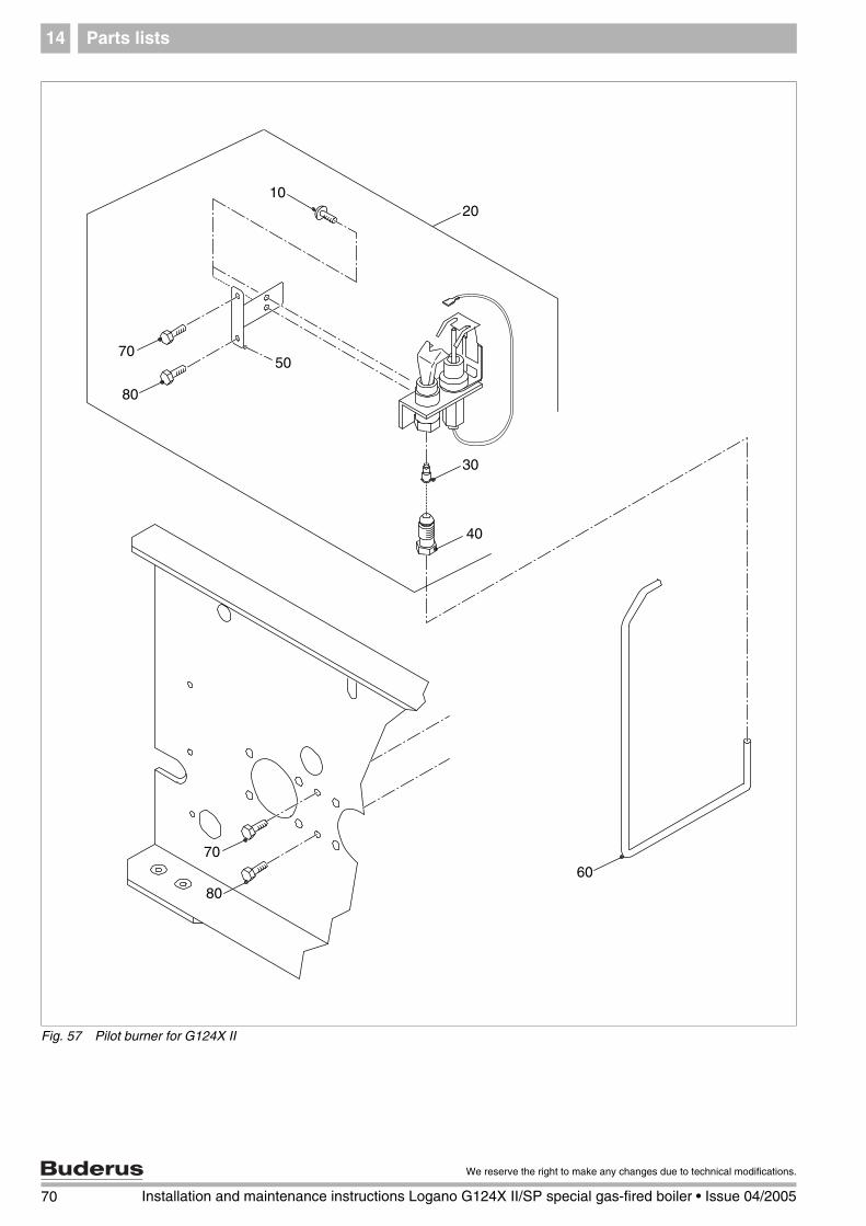
Parts lists14
Fig. 57 Pilot burner for G124X II
10
50
6070
80
30
40
70
80
20
70 Installation and maintenance instructions Logano G124X II/SP special gas-fired boiler • Issue 04/2005
We reserve the right to make any changes due to technical modifications.
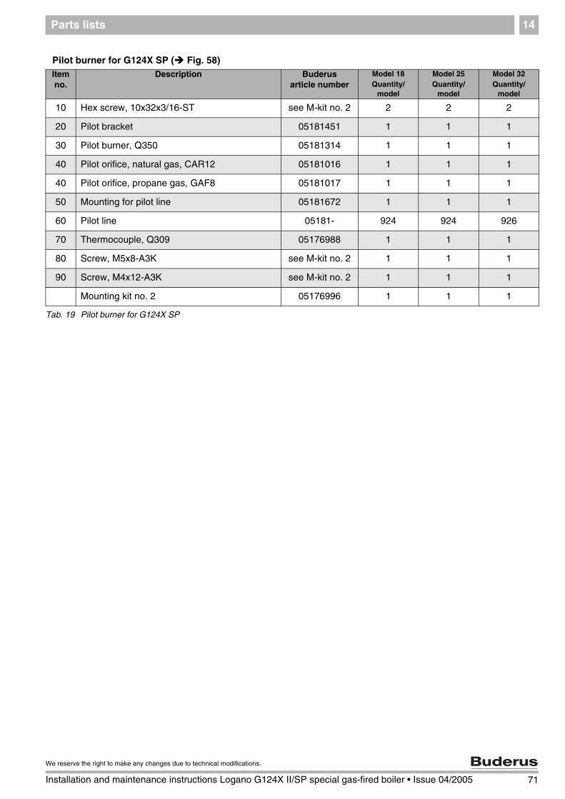
Parts lists 14
Pilot burner for G124X SP ( Fig. 58)Item no.
Description Buderus article number
Model 18Quantity/
model
Model 25Quantity/
model
Model 32Quantity/
model
10 Hex screw, 10x32x3/16-ST see M-kit no. 2 2 2 2
20 Pilot bracket 05181451 1 1 1
30 Pilot burner, Q350 05181314 1 1 1
40 Pilot orifice, natural gas, CAR12 05181016 1 1 1
40 Pilot orifice, propane gas, GAF8 05181017 1 1 1
50 Mounting for pilot line 05181672 1 1 1
60 Pilot line 05181- 924 924 926
70 Thermocouple, Q309 05176988 1 1 1
80 Screw, M5x8-A3K see M-kit no. 2 1 1 1
90 Screw, M4x12-A3K see M-kit no. 2 1 1 1
Mounting kit no. 2 05176996 1 1 1
Tab. 19 Pilot burner for G124X SP
71
We reserve the right to make any changes due to technical modifications.
Installation and maintenance instructions Logano G124X II/SP special gas-fired boiler • Issue 04/2005

Parts lists14
Fig. 58 Pilot burner for G124X SP
80
90
10
3040
50
60
70
20
72 Installation and maintenance instructions Logano G124X II/SP special gas-fired boiler • Issue 04/2005
We reserve the right to make any changes due to technical modifications.

Specifications 15
15 Specifications
Main gas orifice identification and rated manifold pressure for natural gas orifice
Main gas orifice identification and rated manifold pressure for LP gas orifice
1) factory setting
2) use conversion parts only as directed by the technical documentation
The technical documentation is included with the conversion parts (accessories).
Boiler size Number of orifices Main gas orifice identificationfor altitudes [feet]
Rated manifold pressure[in. W.C.]
0–8500 ft1) 8501–12000 ft2)
18 2 285 280 3.6
25 3 275 270 3.5
32 4 270 265 3.6
Tab. 20 Main gas orifice identification and rated manifold pressure for natural gas orifice
Boiler size Number of nozzles Main gas orifice identificationfor altitudes [feet]
Rated manifold pressure[in. W.C.]
0–8500 ft1) 8501–12000 ft2)
18 2 180 175 9.825 3 175 170 10.3
32 4 170 165 10.0
Tab. 21 Main gas orifice identification and rated manifold pressure for LP gas orifice
USER NOTE
If the installation location is over 8500 feet above sea level, please contact Buderus for the required conversion components.
Do not attempt to convert the boiler without the approved Buderus parts and the relevant technical documentation.
73
We reserve the right to make any changes due to technical modifications.
Installation and maintenance instructions Logano G124X II/SP special gas-fired boiler • Issue 04/2005
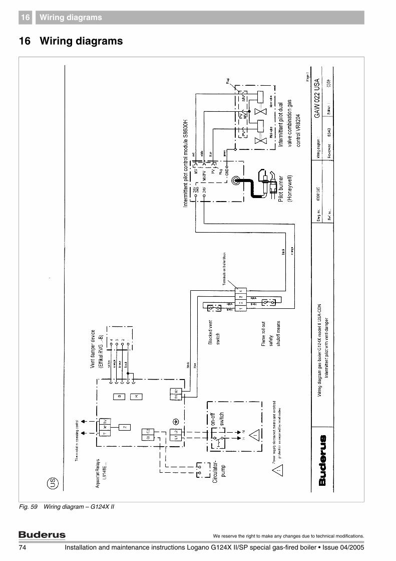
Wiring diagrams16
16 Wiring diagrams
Fig. 59 Wiring diagram – G124X II
74 Installation and maintenance instructions Logano G124X II/SP special gas-fired boiler • Issue 04/2005
We reserve the right to make any changes due to technical modifications.

Wiring diagrams 16
Fig. 60 Wiring diagram – G124X SP
75
We reserve the right to make any changes due to technical modifications.
Installation and maintenance instructions Logano G124X II/SP special gas-fired boiler • Issue 04/2005

Wiring diagrams16
Fig. 61 Wiring diagram – G124X II with vent damper
Fig. 62 Wiring diagram – G124X SP with vent damper
76 Installation and maintenance instructions Logano G124X II/SP special gas-fired boiler • Issue 04/2005
We reserve the right to make any changes due to technical modifications.

Wiring diagrams 16
Fig. 63 Wiring diagram – G124X II/SP with Logamatic control
77
We reserve the right to make any changes due to technical modifications.
Installation and maintenance instructions Logano G124X II/SP special gas-fired boiler • Issue 04/2005
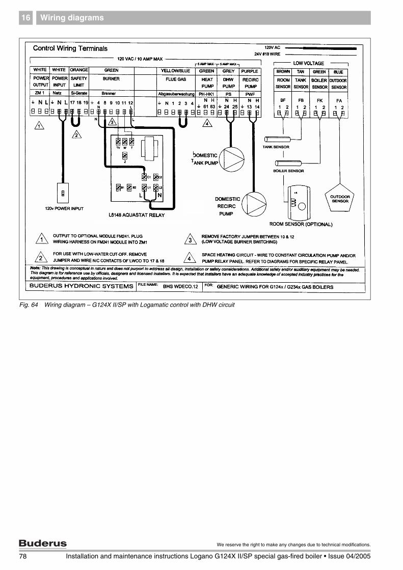
Wiring diagrams16
Fig. 64 Wiring diagram – G124X II/SP with Logamatic control with DHW circuit
78 Installation and maintenance instructions Logano G124X II/SP special gas-fired boiler • Issue 04/2005
We reserve the right to make any changes due to technical modifications.

Note
79
We reserve the right to make any changes due to technical modifications.
Installation and maintenance instructions Logano G124X II/SP special gas-fired boiler • Issue 04/2005

Your local heating contractor:
BBT North America Inc.50 Wentwort Avenue
NH 03053 LondonderryTel: 603-552-1100Fax: 603-421-2719
Toll Free: 1-800-BUDERUSwww.buderus.net