
Installation and Maintenance Helical and Bevel Helical ... and... · 6 Gearbox Design ... 7 Gearbox...
40
Installation and Maintenance KUMERA POWER TRANSMISSION GROUP Helical and Bevel Helical Gearboxes
Transcript of Installation and Maintenance Helical and Bevel Helical ... and... · 6 Gearbox Design ... 7 Gearbox...

Installation and Maintenance
KUMERA POWER TRANSMISSION GROUP
Helical and Bevel Helical Gearboxes

Gearbox installation and maintenance 84 80 27C_EN
Helical and bevel helical gearboxes
© Kumera Drives 2015 2/39
Gearbox installation and maintenance 84 80 27C_EN
Helical and bevel helical gearboxes
© Kumera Drives 2015 3/39
KUMERA DRIVES OY Kumerankatu 2 FIN-11100 Riihimäki FINLAND Tel. +358 20 755 4200 Fax +358 20 755 4220 E-mail [email protected] [email protected] 24h service +358 400 300 644 KUMERA AS P.O. Box 2043 N-3202 Sandefjord NORWAY Tel. +47 33 48 54 54 Fax +47 33 48 54 55 E-mail [email protected]
KUMERA ANTRIEBSTECHNIK GMBH Raiffeisenstrasse 38-40 A-8010 Graz AUSTRIA Tel. +43 316 471 524 0 Fax +43 316 462 550 E-mail [email protected] KUMERA (CHINA) CO, LTD. 168 Meifeng Road, Kunshan 215300, Jiangsu CHINA Tel. +86 512 503 61701 Fax +86 512 503 61710 E-mail [email protected]
Gearbox installation and maintenance 84 80 27C_EN
Helical and bevel helical gearboxes
© Kumera Drives 2015 4/39
Introduction These are general instructions for persons installing, operating or maintaining helical and bevel helical gearboxes made by Kumera Drives Oy. They should read and understand the contents of these instructions. Kumera Drives Oy is not liable for any damages caused by not following these instructions. The gearboxes described in the instructions are similar to the gearboxes being manufactured at the time of writing.
Symbols To be observed during operation and maintenance. An important issue to be observed during installation, operation, and maintenance.
Translation of the original instructions Copyright: These instructions are © Kumera Drives Oy. The instructions must not be used for commercial or competitive purposes without the permission of Kumera Drives Oy.
Gearbox installation and maintenance 84 80 27C_EN
Helical and bevel helical gearboxes
© Kumera Drives 2015 5/39
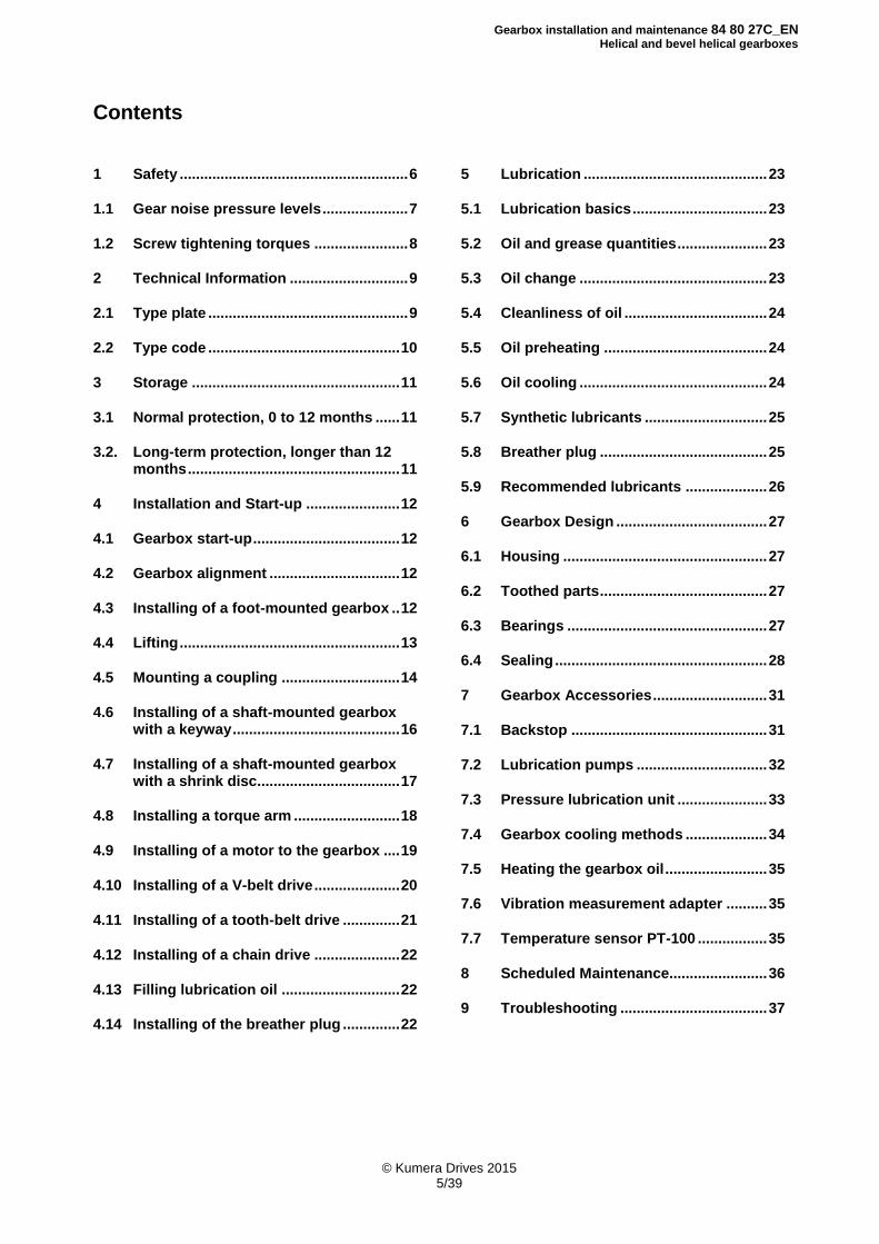
Contents
1 Safety ........................................................ 6
1.1 Gear noise pressure levels ..................... 7
1.2 Screw tightening torques ....................... 8
2 Technical Information ............................. 9
2.1 Type plate ................................................. 9
2.2 Type code ............................................... 10
3 Storage ................................................... 11
3.1 Normal protection, 0 to 12 months ...... 11
3.2. Long-term protection, longer than 12 months .................................................... 11
4 Installation and Start-up ....................... 12
4.1 Gearbox start-up .................................... 12
4.2 Gearbox alignment ................................ 12
4.3 Installing of a foot-mounted gearbox .. 12
4.4 Lifting ...................................................... 13
4.5 Mounting a coupling ............................. 14
4.6 Installing of a shaft-mounted gearbox with a keyway ......................................... 16
4.7 Installing of a shaft-mounted gearbox with a shrink disc................................... 17
4.8 Installing a torque arm .......................... 18
4.9 Installing of a motor to the gearbox .... 19
4.10 Installing of a V-belt drive ..................... 20
4.11 Installing of a tooth-belt drive .............. 21
4.12 Installing of a chain drive ..................... 22
4.13 Filling lubrication oil ............................. 22
4.14 Installing of the breather plug .............. 22
5 Lubrication ............................................. 23
5.1 Lubrication basics ................................. 23
5.2 Oil and grease quantities ...................... 23
5.3 Oil change .............................................. 23
5.4 Cleanliness of oil ................................... 24
5.5 Oil preheating ........................................ 24
5.6 Oil cooling .............................................. 24
5.7 Synthetic lubricants .............................. 25
5.8 Breather plug ......................................... 25
5.9 Recommended lubricants .................... 26
6 Gearbox Design ..................................... 27
6.1 Housing .................................................. 27
6.2 Toothed parts ......................................... 27
6.3 Bearings ................................................. 27
6.4 Sealing .................................................... 28
7 Gearbox Accessories ............................ 31
7.1 Backstop ................................................ 31
7.2 Lubrication pumps ................................ 32
7.3 Pressure lubrication unit ...................... 33
7.4 Gearbox cooling methods .................... 34
7.5 Heating the gearbox oil ......................... 35
7.6 Vibration measurement adapter .......... 35
7.7 Temperature sensor PT-100 ................. 35
8 Scheduled Maintenance........................ 36
9 Troubleshooting .................................... 37
Gearbox installation and maintenance 84 80 27C_EN
Helical and bevel helical gearboxes
© Kumera Drives 2015 6/39
1 Safety In order to prevent any damages, transportation, unpacking, installation and setup shall be performed by professional personnel in accordance with the instructions of Kumera Drives Oy. A gearbox must not be installed in a place or used in a way it was not designed for. Gearboxes are delivered to the customer in accordance with the information supplied to Kumera Drives Oy, and this information must not be deviated from when installing the gearbox. Gearboxes must not be subjected to extra application of load due to installation. Pay attention to safe operation when installing the gearbox. Protect places dangerous to the operator. Do not make any changes to the structure and guards of our gearboxes. Kumera Drives Oy is not liable for structural changes or changes to the guards made by another party. Do not remove the safety devices while the gearbox is in use. Perform any maintenance operations while the gearbox is standing still. When opening inspection covers, make sure that no foreign objects or impurities can enter the gearbox.
Helical and bevel helical gearboxes may generate noise pressure levels in excess of the permissible noise pressure level, depending on the output power level of the gearbox. Persons working near the gearbox must use the appropriate protection. The gearboxes may warm up to the extent that their surface becomes hot. Avoid touching the gear surface during operation. The gearbox was packed at the Kumera Drives Oy factory according to the terms of delivery, in such a way that it withstands normal transportation. When lifting the gearbox, use its lifting eyes. See the machine plate for the weight of the gear. The gear lifting eyes are only for lifting the gearbox, not for accessories such as an electric motor. Do not use the shafts when lifting. Report any damage during transportation immediately to Kumera Drives Oy.
Gearbox installation and maintenance 84 80 27C_EN
Helical and bevel helical gearboxes
© Kumera Drives 2015 7/39
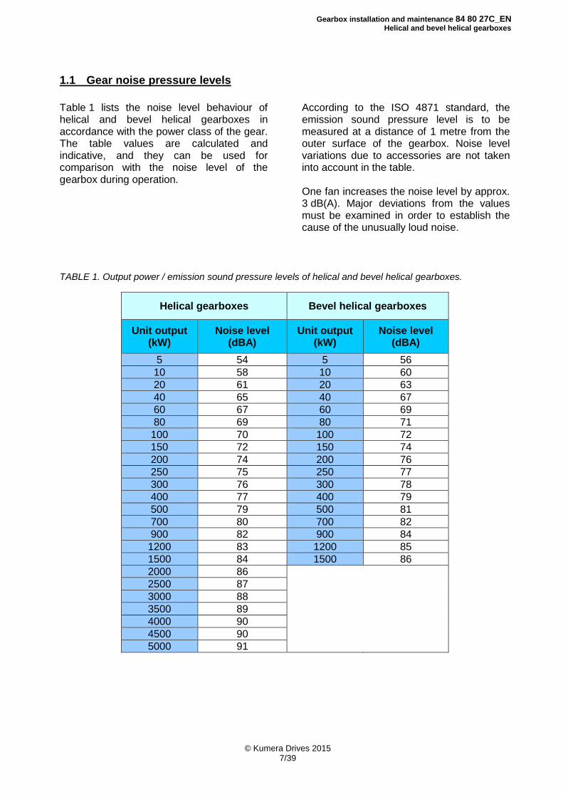
1.1 Gear noise pressure levels
Table 1 lists the noise level behaviour of helical and bevel helical gearboxes in accordance with the power class of the gear. The table values are calculated and indicative, and they can be used for comparison with the noise level of the gearbox during operation.
According to the ISO 4871 standard, the emission sound pressure level is to be measured at a distance of 1 metre from the outer surface of the gearbox. Noise level variations due to accessories are not taken into account in the table. One fan increases the noise level by approx. 3 dB(A). Major deviations from the values must be examined in order to establish the cause of the unusually loud noise.
TABLE 1. Output power / emission sound pressure levels of helical and bevel helical gearboxes.
Helical gearboxes Bevel helical gearboxes
Unit output (kW)
Noise level (dBA)
Unit output (kW)
Noise level (dBA)
5 54 5 56
10 58 10 60
20 61 20 63
40 65 40 67
60 67 60 69
80 69 80 71
100 70 100 72
150 72 150 74
200 74 200 76
250 75 250 77
300 76 300 78
400 77 400 79
500 79 500 81
700 80 700 82
900 82 900 84
1200 83 1200 85
1500 84 1500 86
2000 86
2500 87
3000 88
3500 89
4000 90
4500 90
5000 91
Gearbox installation and maintenance 84 80 27C_EN
Helical and bevel helical gearboxes
© Kumera Drives 2015 8/39
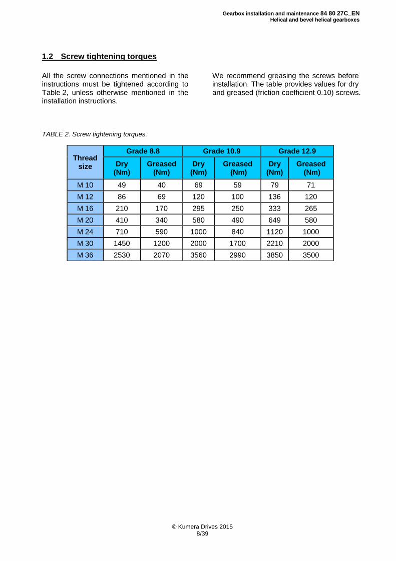
1.2 Screw tightening torques
All the screw connections mentioned in the instructions must be tightened according to Table 2, unless otherwise mentioned in the installation instructions.
We recommend greasing the screws before installation. The table provides values for dry and greased (friction coefficient 0.10) screws.
TABLE 2. Screw tightening torques.
Thread size
Grade 8.8 Grade 10.9 Grade 12.9
Dry (Nm)
Greased (Nm)
Dry (Nm)
Greased (Nm)
Dry (Nm)
Greased (Nm)
M 10 49 40 69 59 79 71
M 12 86 69 120 100 136 120
M 16 210 170 295 250 333 265
M 20 410 340 580 490 649 580
M 24 710 590 1000 840 1120 1000
M 30 1450 1200 2000 1700 2210 2000
M 36 2530 2070 3560 2990 3850 3500

Gearbox installation and maintenance 84 80 27C_EN
Helical and bevel helical gearboxes
© Kumera Drives 2015 9/39
2 Technical Information
2.1 Type plate
A type plate is installed during packing onto all the gearboxes supplied by us. The plate contains the required identification information and lubrication recommendations of the gearbox. Example of the gearbox type plate:
Type: Gearbox type (see page 10)
Serial No. Gearbox serial number
Year Manufacturing year
Gear ratio Exact gear ratio
Weight: Weight without oil
Lubricant Recommended viscosity of lubrication oil
Oil qty Indicative oil capacity, to be checked using the oil sight glass or dipstick
P1N (n1) Nominal power of the gearbox
Ksf : Selection factor
ATEX Note: If the gearbox is ATEX certified, the ATEX mark and class are marked
in the bottom left corner
Gearbox installation and maintenance 84 80 27C_EN
Helical and bevel helical gearboxes
© Kumera Drives 2015 10/39
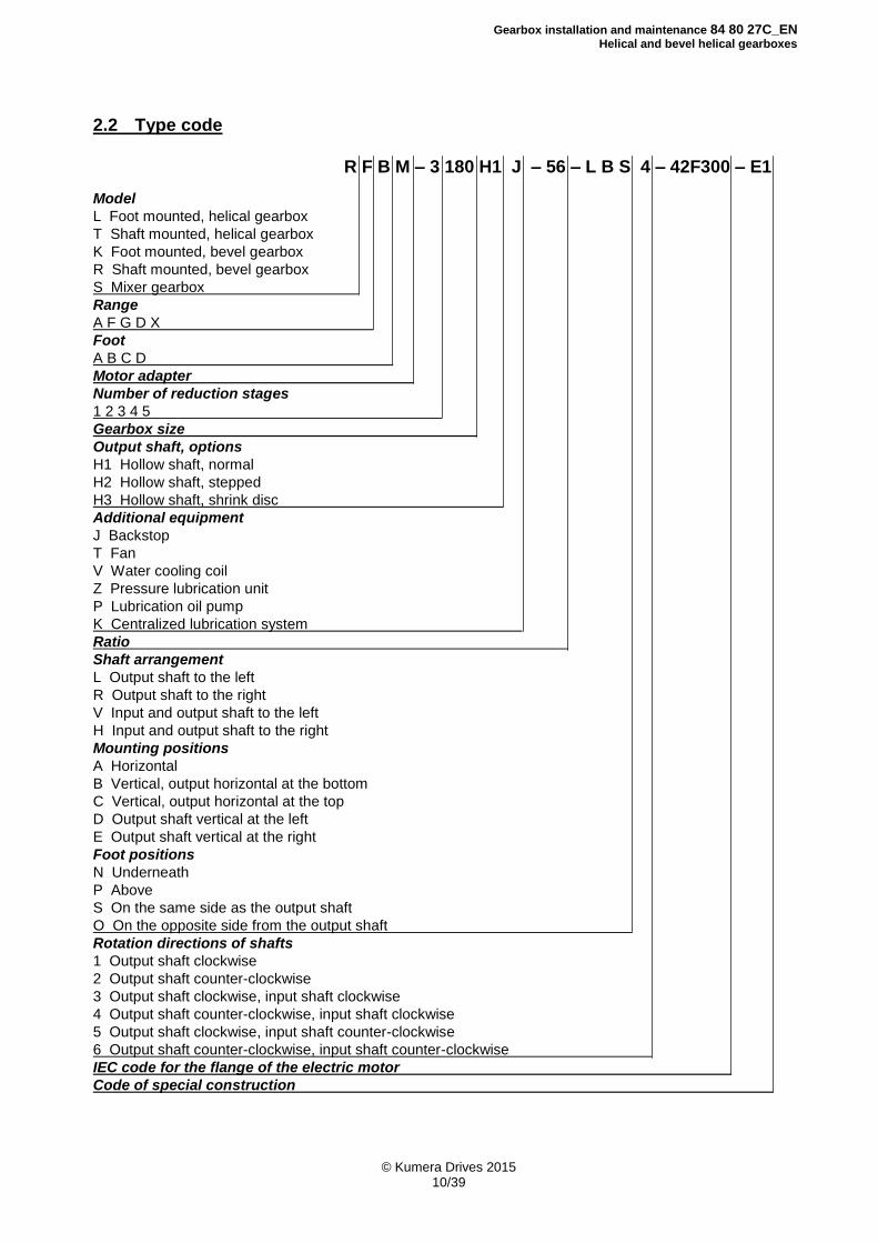
2.2 Type code
R F B M – 3 180 H1 J – 56 – L B S 4 – 42F300 – E1 Model
L Foot mounted, helical gearbox
T Shaft mounted, helical gearbox
K Foot mounted, bevel gearbox
R Shaft mounted, bevel gearbox
S Mixer gearbox
Range
A F G D X
Foot
A B C D
Motor adapter
Number of reduction stages
1 2 3 4 5
Gearbox size
Output shaft, options
H1 Hollow shaft, normal
H2 Hollow shaft, stepped
H3 Hollow shaft, shrink disc
Additional equipment
J Backstop
T Fan
V Water cooling coil
Z Pressure lubrication unit
P Lubrication oil pump
K Centralized lubrication system
Ratio
Shaft arrangement
L Output shaft to the left
R Output shaft to the right
V Input and output shaft to the left
H Input and output shaft to the right
Mounting positions
A Horizontal
B Vertical, output horizontal at the bottom
C Vertical, output horizontal at the top
D Output shaft vertical at the left
E Output shaft vertical at the right
Foot positions
N Underneath
P Above
S On the same side as the output shaft
O On the opposite side from the output shaft
Rotation directions of shafts
1 Output shaft clockwise
2 Output shaft counter-clockwise
3 Output shaft clockwise, input shaft clockwise
4 Output shaft counter-clockwise, input shaft clockwise
5 Output shaft clockwise, input shaft counter-clockwise
6 Output shaft counter-clockwise, input shaft counter-clockwise
IEC code for the flange of the electric motor
Code of special construction
Gearbox installation and maintenance 84 80 27C_EN
Helical and bevel helical gearboxes
© Kumera Drives 2015 11/39
3 Storage
3.1 Normal protection, 0 to 12 months
The gearboxes have been treated as follows before delivery: The internal parts of the gearbox are protected by oil that spreads to their surfaces during the test run. Gear oil is used in the test run. THE GEARBOX IS DELIVERED WITHOUT OIL! The shaft ends and other machined surfaces outside the gearboxes are treated with anti-corrosive agent. Remove the anti-corrosive agent with solvent before start-up. Anti-corrosive agent is sprayed inside the gearbox. The gearbox is made airtight by replacing the breather plug with a pipe plug. The effect of the agent is based on slow evaporation and accumulation on the metal surfaces. An invisible layer is formed on the metal surfaces and prevents corrosion by passivating the metal. This provides protection for storage for up to 12 months in dry indoor spaces with an even temperature. In gearboxes with a labyrinth sealing, the gas can escape, in which case the gearbox is enclosed in airtight plastic that prevents the agent from escaping.
3.2. Long-term protection, longer than 12 months
The long-term protection is to be agreed separately when ordering. Repeat rust proofing of the gearbox every 12 months using protective agent. You need not remove the protective agent during start-up. Alternatively, you can fill the gearbox with oil. When filling the gearbox with oil, use the quantity indicated in the type plate. At the same time, replace the breather with a pipe plug. In addition to rust proofing, the oil protects the bearings from pitting during transportation. During storage, use the gearbox every 2 months manually so that all the shafts rotate at least half a turn. This spreads the oil onto the gear surfaces. Replace the pipe plug with the breather before start-up. In case it is not possible to operate the gearbox or rotate the shafts during storage, fill the gearbox completely with oil. Change the oil during start-up. This provides protection for long-term storage in dry indoor spaces with an even temperature. THE NORMAL PROTECTION OR LONG-TERM PROTECTION TREATMENT DOES NOT PROTECT THE GEARBOX DURING TRANSPORT BY SEA.
Gearbox installation and maintenance 84 80 27C_EN
Helical and bevel helical gearboxes
© Kumera Drives 2015 12/39
4 Installation and Start-up
THE GEARBOX IS DELIVERED WITHOUT OIL!
4.1 Gearbox start-up
All gearboxes are test-run prior to delivery from the factory. However, the test run does not correspond to actual load conditions: for this reason, you should at first operate the gearbox at a partial load. During the running-in, monitor the operating sound, running smoothness, temperature, lubrication and oil tightness of the gearbox. If you notice something abnormal during running-in, detect and eliminate the cause of the problem before the final start-up. During operation, pay attention to the operating sound, warm-up, vibration and oil circulation. Overheating, for example, is often caused by an excessive amount of oil in the gearbox. For gearbox operation, the recommended maximum temperature is +90°C. In higher temperatures, use special lubricants and/or additional cooling. The oil change interval is shorter in high temperatures.
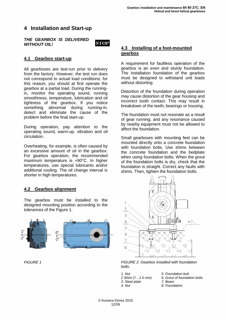
4.2 Gearbox alignment
The gearbox must be installed to the designed mounting position according to the tolerances of the Figure 1.
FIGURE 1
4.3 Installing of a foot-mounted gearbox
A requirement for faultless operation of the gearbox is an even and sturdy foundation. The installation foundation of the gearbox must be designed to withstand unit loads without distorting.
Distortion of the foundation during operation may cause distortion of the gear housing and incorrect tooth contact. This may result in breakdown of the teeth, bearings or housing.
The foundation must not resonate as a result of gear running, and any resonance caused by nearby equipment must not be allowed to affect the foundation.
Small gearboxes with mounting feet can be mounted directly onto a concrete foundation with foundation bolts. Use shims between the concrete foundation and the bedplate when using foundation bolts. When the grout of the foundation bolts is dry, check that the foundation is straight. Correct any faults with shims. Then, tighten the foundation bolts.
FIGURE 2. Gearbox installed with foundation bolts.
1. Nut 5. Foundation bolt 2 Shim (1…1.5 mm) 6. Grout of foundation bolts 3. Steel plate 7. Beam 4. Nut 8. Foundation
Gearbox installation and maintenance 84 80 27C_EN
Helical and bevel helical gearboxes
© Kumera Drives 2015 13/39
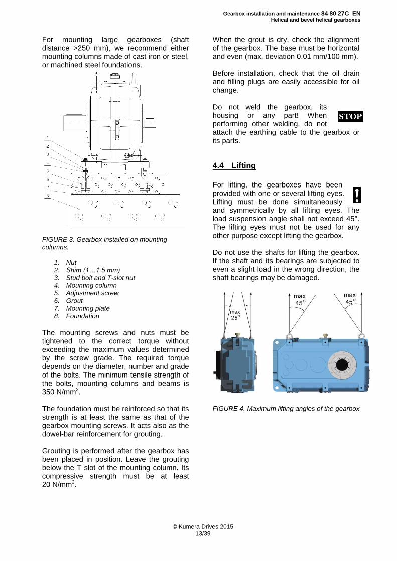
For mounting large gearboxes (shaft distance >250 mm), we recommend either mounting columns made of cast iron or steel, or machined steel foundations.
FIGURE 3. Gearbox installed on mounting columns.
1. Nut 2. Shim (1…1.5 mm) 3. Stud bolt and T-slot nut 4. Mounting column 5. Adjustment screw 6. Grout 7. Mounting plate 8. Foundation
The mounting screws and nuts must be tightened to the correct torque without exceeding the maximum values determined by the screw grade. The required torque depends on the diameter, number and grade of the bolts. The minimum tensile strength of the bolts, mounting columns and beams is 350 N/mm2. The foundation must be reinforced so that its strength is at least the same as that of the gearbox mounting screws. It acts also as the dowel-bar reinforcement for grouting. Grouting is performed after the gearbox has been placed in position. Leave the grouting below the T slot of the mounting column. Its compressive strength must be at least 20 N/mm2.
When the grout is dry, check the alignment of the gearbox. The base must be horizontal and even (max. deviation 0.01 mm/100 mm). Before installation, check that the oil drain and filling plugs are easily accessible for oil change. Do not weld the gearbox, its housing or any part! When performing other welding, do not attach the earthing cable to the gearbox or its parts.
4.4 Lifting
For lifting, the gearboxes have been provided with one or several lifting eyes. Lifting must be done simultaneously and symmetrically by all lifting eyes. The load suspension angle shall not exceed 45°. The lifting eyes must not be used for any other purpose except lifting the gearbox. Do not use the shafts for lifting the gearbox. If the shaft and its bearings are subjected to even a slight load in the wrong direction, the shaft bearings may be damaged.
FIGURE 4. Maximum lifting angles of the gearbox
Gearbox installation and maintenance 84 80 27C_EN
Helical and bevel helical gearboxes
© Kumera Drives 2015 14/39
4.5 Mounting a coupling
To mount a coupling onto the shaft, heat the coupling halves to approximately +100°C or draw them onto the shaft using the tapped holes at the ends of the shafts.
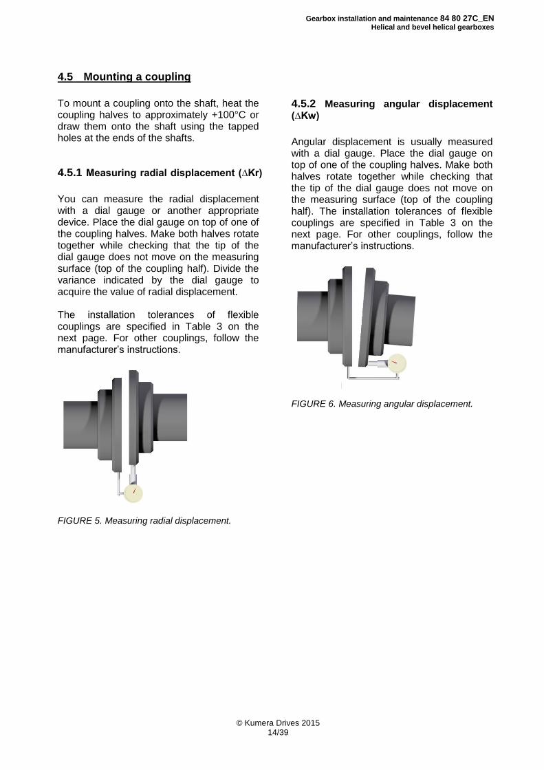
4.5.1 Measuring radial displacement (∆Kr)
You can measure the radial displacement with a dial gauge or another appropriate device. Place the dial gauge on top of one of the coupling halves. Make both halves rotate together while checking that the tip of the dial gauge does not move on the measuring surface (top of the coupling half). Divide the variance indicated by the dial gauge to acquire the value of radial displacement. The installation tolerances of flexible couplings are specified in Table 3 on the next page. For other couplings, follow the manufacturer’s instructions.
FIGURE 5. Measuring radial displacement.
4.5.2 Measuring angular displacement (∆Kw)
Angular displacement is usually measured with a dial gauge. Place the dial gauge on top of one of the coupling halves. Make both halves rotate together while checking that the tip of the dial gauge does not move on the measuring surface (top of the coupling half). The installation tolerances of flexible couplings are specified in Table 3 on the next page. For other couplings, follow the manufacturer’s instructions.
FIGURE 6. Measuring angular displacement.
Gearbox installation and maintenance 84 80 27C_EN
Helical and bevel helical gearboxes
© Kumera Drives 2015 15/39
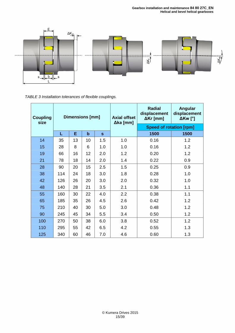
TABLE 3 Installation tolerances of flexible couplings.
Coupling size
Dimensions [mm] Axial offset Δka [mm]
Radial displacement
ΔKr [mm]
Angular displacement
ΔKw [°]
Speed of rotation [rpm]
L E b s 1500 1500
14 35 13 10 1.5 1.0 0.16 1.2
15 28 8 6 1.0 1.0 0.16 1.2
19 66 16 12 2.0 1.2 0.20 1.2
21 78 18 14 2.0 1.4 0.22 0.9
28 90 20 15 2.5 1.5 0.25 0.9
38 114 24 18 3.0 1.8 0.28 1.0
42 126 26 20 3.0 2.0 0.32 1.0
48 140 28 21 3.5 2.1 0.36 1.1
55 160 30 22 4.0 2.2 0.38 1.1
65 185 35 26 4.5 2.6 0.42 1.2
75 210 40 30 5.0 3.0 0.48 1.2
90 245 45 34 5.5 3.4 0.50 1.2
100 270 50 38 6.0 3.8 0.52 1.2
110 295 55 42 6.5 4.2 0.55 1.3
125 340 60 46 7.0 4.6 0.60 1.3
Gearbox installation and maintenance 84 80 27C_EN
Helical and bevel helical gearboxes
© Kumera Drives 2015 16/39
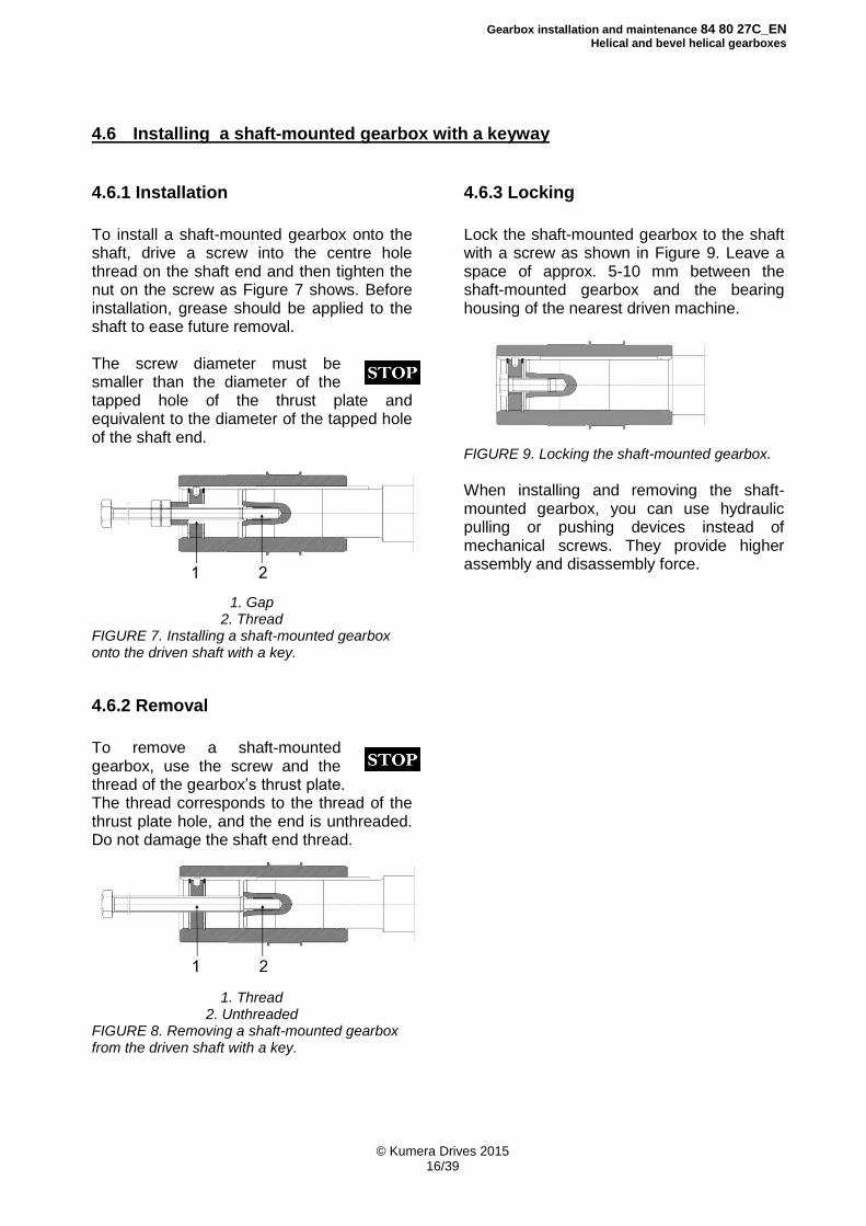
4.6 Installing a shaft-mounted gearbox with a keyway
4.6.1 Installation
To install a shaft-mounted gearbox onto the shaft, drive a screw into the centre hole thread on the shaft end and then tighten the nut on the screw as Figure 7 shows. Before installation, grease should be applied to the shaft to ease future removal. The screw diameter must be smaller than the diameter of the tapped hole of the thrust plate and equivalent to the diameter of the tapped hole of the shaft end.
1. Gap
2. Thread FIGURE 7. Installing a shaft-mounted gearbox onto the driven shaft with a key.
4.6.2 Removal
To remove a shaft-mounted gearbox, use the screw and the thread of the gearbox’s thrust plate. The thread corresponds to the thread of the thrust plate hole, and the end is unthreaded. Do not damage the shaft end thread.
1. Thread
2. Unthreaded FIGURE 8. Removing a shaft-mounted gearbox from the driven shaft with a key.
4.6.3 Locking
Lock the shaft-mounted gearbox to the shaft with a screw as shown in Figure 9. Leave a space of approx. 5-10 mm between the shaft-mounted gearbox and the bearing housing of the nearest driven machine.
FIGURE 9. Locking the shaft-mounted gearbox.
When installing and removing the shaft-mounted gearbox, you can use hydraulic pulling or pushing devices instead of mechanical screws. They provide higher assembly and disassembly force.
Gearbox installation and maintenance 84 80 27C_EN
Helical and bevel helical gearboxes
© Kumera Drives 2015 17/39
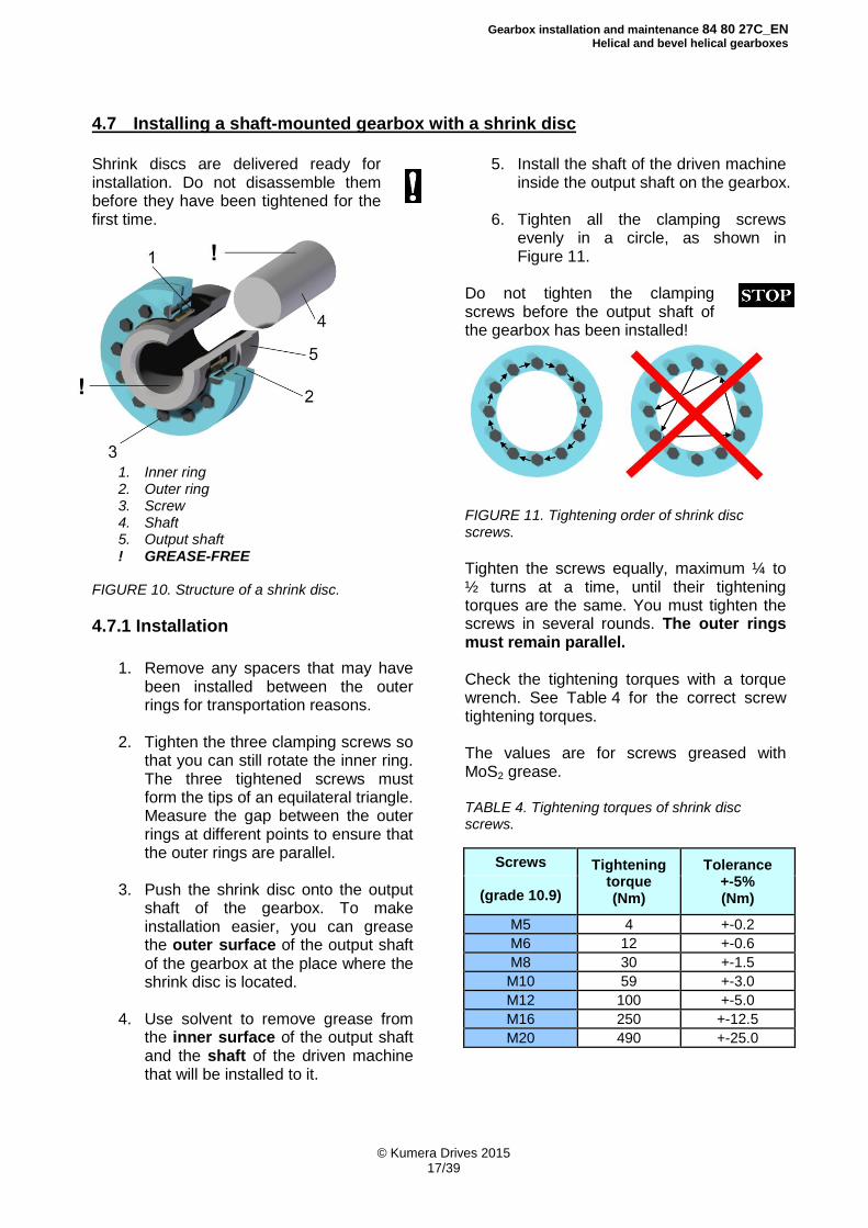
4.7 Installing a shaft-mounted gearbox with a shrink disc
Shrink discs are delivered ready for installation. Do not disassemble them before they have been tightened for the first time.
1. Inner ring 2. Outer ring 3. Screw 4. Shaft 5. Output shaft ! GREASE-FREE
FIGURE 10. Structure of a shrink disc.
4.7.1 Installation
1. Remove any spacers that may have
been installed between the outer rings for transportation reasons.
2. Tighten the three clamping screws so
that you can still rotate the inner ring. The three tightened screws must form the tips of an equilateral triangle. Measure the gap between the outer rings at different points to ensure that the outer rings are parallel.
3. Push the shrink disc onto the output
shaft of the gearbox. To make installation easier, you can grease the outer surface of the output shaft of the gearbox at the place where the shrink disc is located.
4. Use solvent to remove grease from
the inner surface of the output shaft and the shaft of the driven machine that will be installed to it.
5. Install the shaft of the driven machine inside the output shaft on the gearbox.
6. Tighten all the clamping screws
evenly in a circle, as shown in Figure 11.
Do not tighten the clamping screws before the output shaft of the gearbox has been installed!
FIGURE 11. Tightening order of shrink disc screws.
Tighten the screws equally, maximum ¼ to ½ turns at a time, until their tightening torques are the same. You must tighten the screws in several rounds. The outer rings must remain parallel. Check the tightening torques with a torque wrench. See Table 4 for the correct screw tightening torques. The values are for screws greased with MoS2 grease. TABLE 4. Tightening torques of shrink disc screws.
Screws Tightening torque (Nm)
Tolerance +-5% (Nm) (grade 10.9)
M5 4 +-0.2
M6 12 +-0.6
M8 30 +-1.5
M10 59 +-3.0
M12 100 +-5.0
M16 250 +-12.5
M20 490 +-25.0
Gearbox installation and maintenance 84 80 27C_EN
Helical and bevel helical gearboxes
© Kumera Drives 2015 18/39
4.7.2 Removal
1. Remove the clamping screws evenly,
by loosening them in the opposite order to that of tightening. Initially, loosen each clamping screw only ¼ of a round. In this way, you can avoid distortion of the outer ring. Never unscrew the clamping screws.
2. Remove the shaft of the driven
machine from the output shaft of the gearbox. Remove any corrosion that has formed between the shafts.
3. Remove the shrink disc from the
output shaft of the gearbox.
4.7.3 Cleaning and lubrication
You need not detach the removed shrink discs from each other or lubricate them again before tightening them again. However, clean and lubricate dirty shrink discs. Grease the clamping screws with multi-purpose grease and replace damaged seal rings. When replacing the inner ring, the bevel surfaces must be greased (e.g. MoS2).
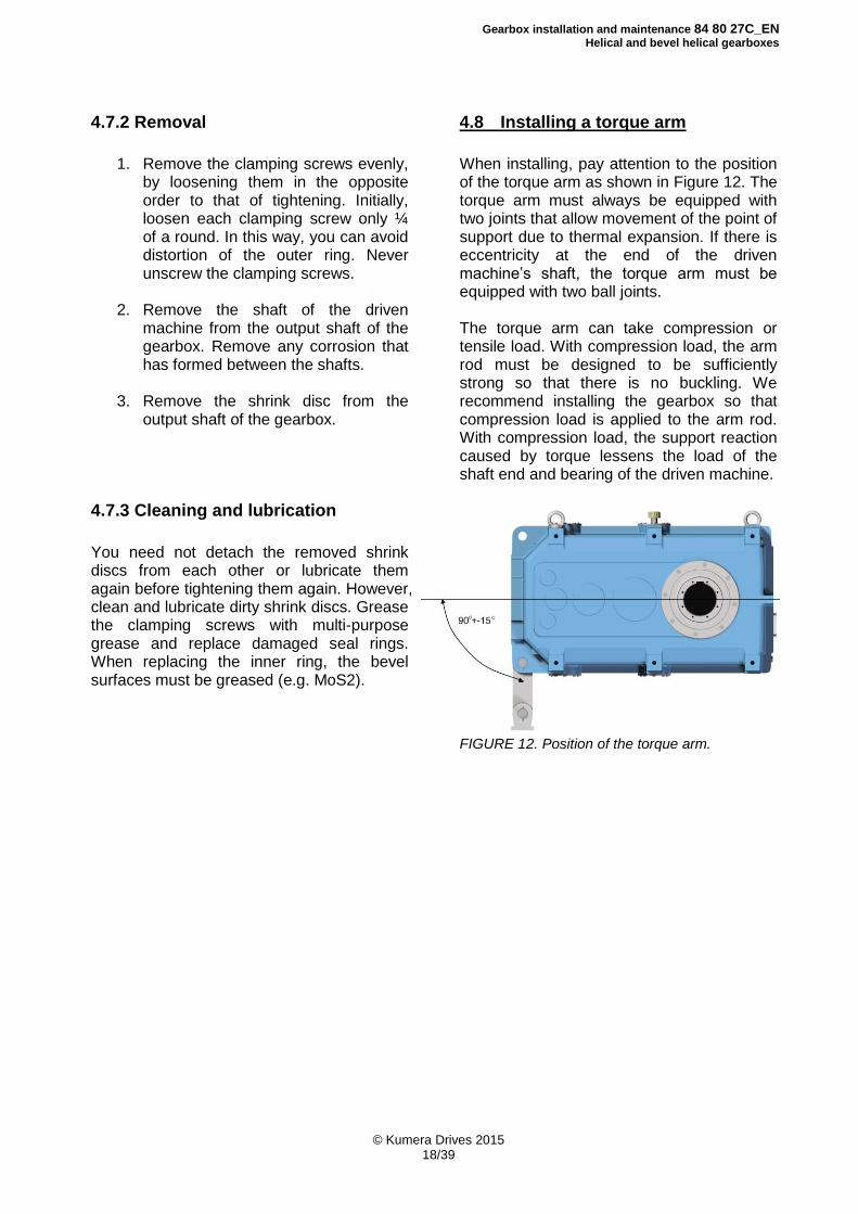
4.8 Installing a torque arm
When installing, pay attention to the position of the torque arm as shown in Figure 12. The torque arm must always be equipped with two joints that allow movement of the point of support due to thermal expansion. If there is eccentricity at the end of the driven machine’s shaft, the torque arm must be equipped with two ball joints. The torque arm can take compression or tensile load. With compression load, the arm rod must be designed to be sufficiently strong so that there is no buckling. We recommend installing the gearbox so that compression load is applied to the arm rod. With compression load, the support reaction caused by torque lessens the load of the shaft end and bearing of the driven machine.
FIGURE 12. Position of the torque arm.
Gearbox installation and maintenance 84 80 27C_EN
Helical and bevel helical gearboxes
© Kumera Drives 2015 19/39
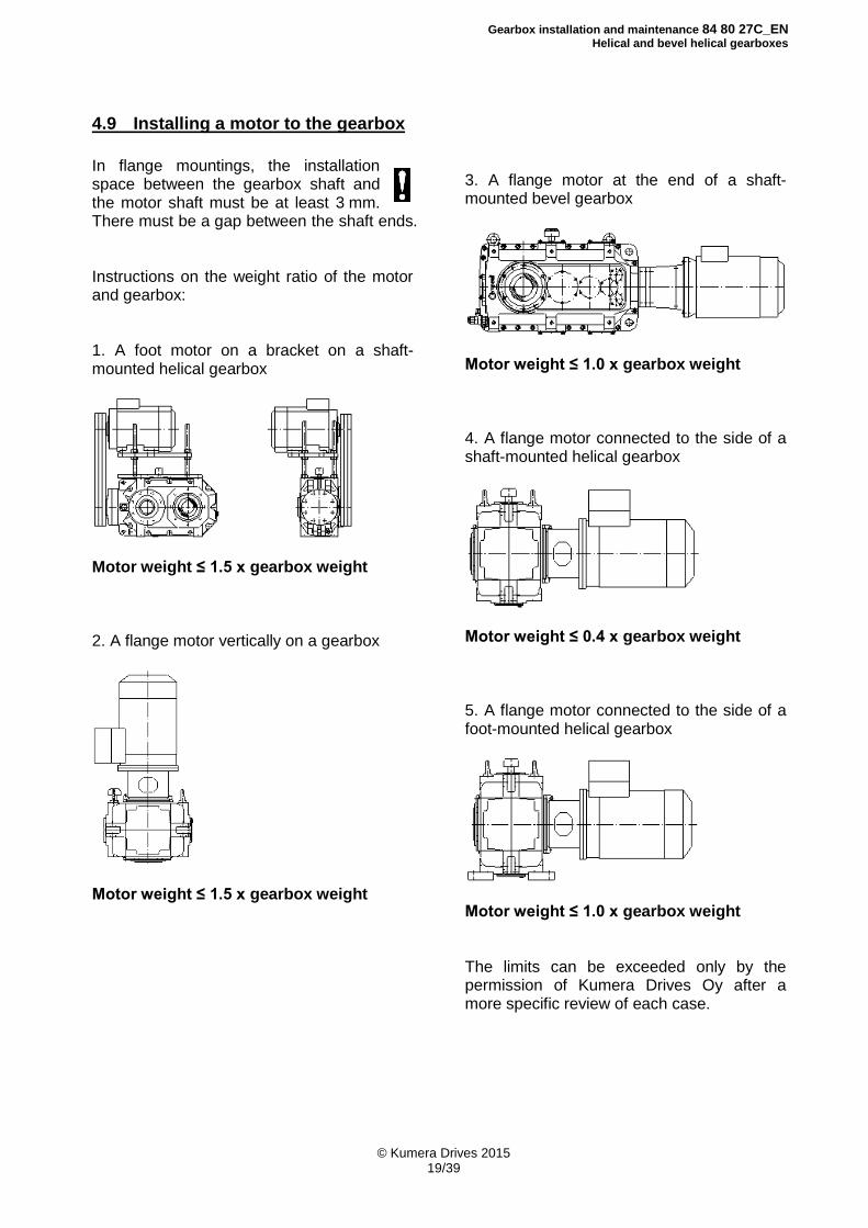
4.9 Installing a motor to the gearbox
In flange mountings, the installation space between the gearbox shaft and the motor shaft must be at least 3 mm. There must be a gap between the shaft ends. Instructions on the weight ratio of the motor and gearbox: 1. A foot motor on a bracket on a shaft-mounted helical gearbox
Motor weight ≤ 1.5 x gearbox weight 2. A flange motor vertically on a gearbox
Motor weight ≤ 1.5 x gearbox weight
3. A flange motor at the end of a shaft-mounted bevel gearbox
Motor weight ≤ 1.0 x gearbox weight 4. A flange motor connected to the side of a shaft-mounted helical gearbox
Motor weight ≤ 0.4 x gearbox weight 5. A flange motor connected to the side of a foot-mounted helical gearbox
Motor weight ≤ 1.0 x gearbox weight The limits can be exceeded only by the permission of Kumera Drives Oy after a more specific review of each case.
Gearbox installation and maintenance 84 80 27C_EN
Helical and bevel helical gearboxes
© Kumera Drives 2015 20/39
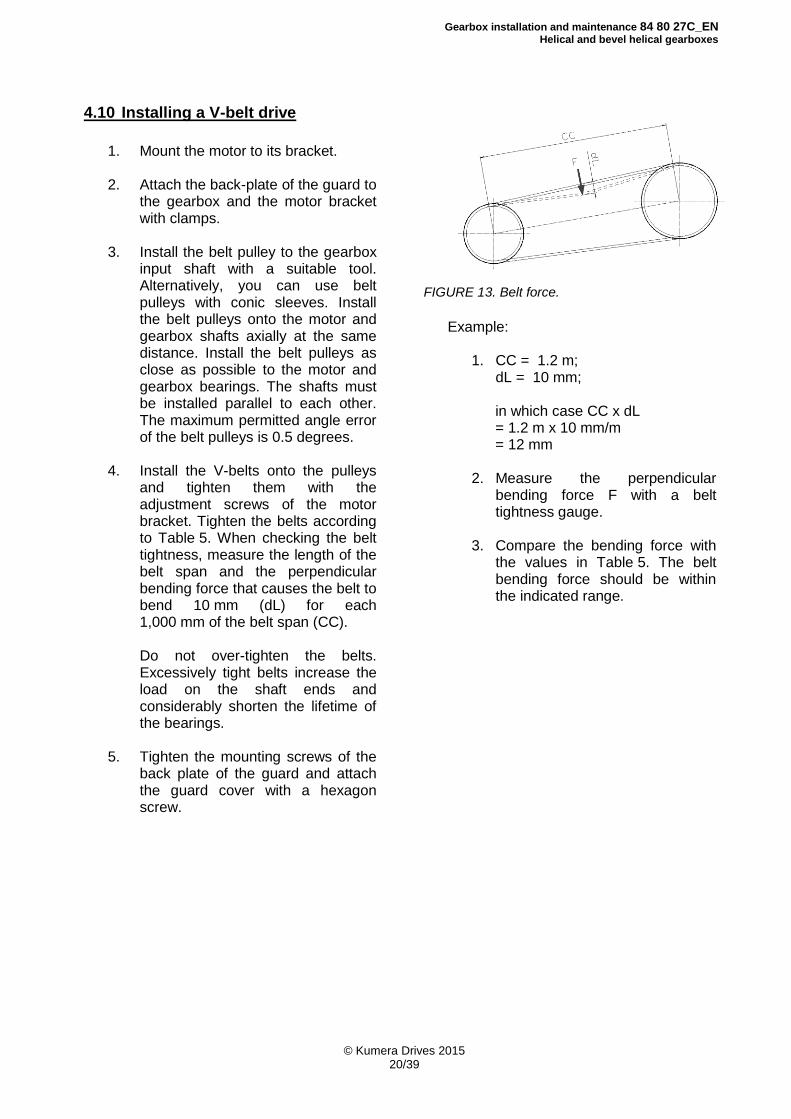
4.10 Installing a V-belt drive
1. Mount the motor to its bracket. 2. Attach the back-plate of the guard to
the gearbox and the motor bracket with clamps.
3. Install the belt pulley to the gearbox
input shaft with a suitable tool. Alternatively, you can use belt pulleys with conic sleeves. Install the belt pulleys onto the motor and gearbox shafts axially at the same distance. Install the belt pulleys as close as possible to the motor and gearbox bearings. The shafts must be installed parallel to each other. The maximum permitted angle error of the belt pulleys is 0.5 degrees.
4. Install the V-belts onto the pulleys
and tighten them with the adjustment screws of the motor bracket. Tighten the belts according to Table 5. When checking the belt tightness, measure the length of the belt span and the perpendicular bending force that causes the belt to bend 10 mm (dL) for each 1,000 mm of the belt span (CC).
Do not over-tighten the belts. Excessively tight belts increase the load on the shaft ends and considerably shorten the lifetime of the bearings.
5. Tighten the mounting screws of the
back plate of the guard and attach the guard cover with a hexagon screw.
FIGURE 13. Belt force.
Example:
1. CC = 1.2 m; dL = 10 mm;
in which case CC x dL = 1.2 m x 10 mm/m = 12 mm 2. Measure the perpendicular
bending force F with a belt tightness gauge.
3. Compare the bending force with
the values in Table 5. The belt bending force should be within the indicated range.
Gearbox installation and maintenance 84 80 27C_EN
Helical and bevel helical gearboxes
© Kumera Drives 2015 21/39
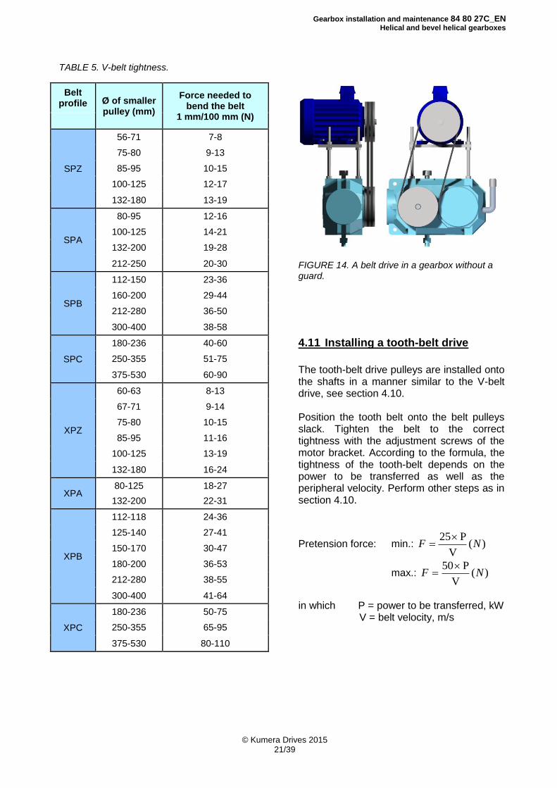
TABLE 5. V-belt tightness.
Belt profile Ø of smaller
pulley (mm)
Force needed to bend the belt
1 mm/100 mm (N)
SPZ
56-71 7-8
75-80 9-13
85-95 10-15
100-125 12-17
132-180 13-19
SPA
80-95 12-16
100-125 14-21
132-200 19-28
212-250 20-30
SPB
112-150 23-36
160-200 29-44
212-280 36-50
300-400 38-58
SPC
180-236 40-60
250-355 51-75
375-530 60-90
XPZ
60-63 8-13
67-71 9-14
75-80 10-15
85-95 11-16
100-125 13-19
132-180 16-24
XPA 80-125 18-27
132-200 22-31
XPB
112-118 24-36
125-140 27-41
150-170 30-47
180-200 36-53
212-280 38-55
300-400 41-64
XPC
180-236 50-75
250-355 65-95
375-530 80-110
FIGURE 14. A belt drive in a gearbox without a guard.
4.11 Installing a tooth-belt drive
The tooth-belt drive pulleys are installed onto the shafts in a manner similar to the V-belt drive, see section 4.10. Position the tooth belt onto the belt pulleys slack. Tighten the belt to the correct tightness with the adjustment screws of the motor bracket. According to the formula, the tightness of the tooth-belt depends on the power to be transferred as well as the peripheral velocity. Perform other steps as in section 4.10.
Pretension force: min.: )(V
P 25NF
max.: )(V
P 50NF
in which P = power to be transferred, kW
V = belt velocity, m/s
Gearbox installation and maintenance 84 80 27C_EN
Helical and bevel helical gearboxes
© Kumera Drives 2015 22/39
4.12 Installing of a chain drive
A chain wheel is normally installed to the slow shaft of the gearbox by heating it to a temperature of +80 - +120°C. Small chain wheels can be installed with a suitable pulling tool, using the threaded centre holes of the shaft ends. Install the chain wheels onto the gearbox and driven machine shafts axially at the same distance. Install the chain as close as possible to the bearings, so that the bending moment at the shaft ends remains as low as possible. This also minimizes the bearing loads. Install the shafts parallel to each other in order to balance the load on the chain and chain wheels. The maximum angular and parallel misalignment error is ±1/300. The allowed angle error between the shafts depends on the distance between the shafts. At a distance of less than 1 metre, the allowed error is ±1 mm. At 1-10 m, the error is calculated with the formula (distance between shafts [mm])/1,000. At a distance of more than 10 metres, the allowed error is ±10 mm. When selecting chain drives, make sure that the allowed loads of the gearbox shaft ends are not exceeded.
4.13 Filling lubrication oil
THE GEARBOX IS DELIVERED WITHOUT OIL! 1. Before start-up, the gearbox must be
filled with oil specified in the type plate of the gearbox or according to the included lubrication recommendation.
2. To check the correct oil level:
With the oil sight glass: fill the gearbox with oil up to the middle of the oil sight glass.
With the oil level sight glass: fill the gearbox with oil up to between the marks.
With the oil plug: add oil to the gearbox until it leaks out of the opened overflow hole.
With the dipstick: fill the gearbox with oil up to the area between the dipstick marks.
3. Check the oil level when the gearbox is
at a standstill and the oil has cooled. Avoid overfilling when adding oil. Too much oil may cause the gearbox to heat up above the allowed limit.
For more information on lubrication and lubricating oils, see Chapter 5.
4.14 Installing the breather plug
Before starting up the gearbox, make sure that the breather plug is in place and operational.
Gearbox installation and maintenance 84 80 27C_EN
Helical and bevel helical gearboxes
© Kumera Drives 2015 23/39
5 Lubrication THE GEARBOX IS DELIVERED WITHOUT OIL!
5.1 Lubrication basics
Depending on the gearbox and operating conditions, four different lubrication methods are used.
5.1.1. Splash lubrication
Splash lubrication is used for gearboxes with peripheral velocities of 2-14 m/s. In this case, it is essential to ensure that the amount of oil in the gearbox is correct. Too low an amount causes insufficient lubrication of the gearbox, and too high an amount may cause the gearbox to overheat over the allowed limit.
5.1.2 Pressure lubrication Pressure lubrication is used for gearboxes with peripheral velocities higher than 14 m/s. Utmost care should be taken to ensure a continuous flow of oil onto the mesh point of the gear. Pressure lubrication can also be used for gearboxes with slower velocities, if required by the gearbox.
5.1.3 Oil bath lubrication Oil bath lubrication can be used in slow speed gearboxes with peripheral velocities slower than 4 m/s. This method provides efficient lubrication of the bearings and gears. Due to the low peripheral velocity, no harmful warming of the lubricant occurs in the gearbox.
5.1.4 Grease lubrication Grease lubrication is used in gearboxes with peripheral velocities slower than 5 m/s. Grease lubrication is especially suitable for gearboxes in occasional operation undergoing frequent starts. The grease remains on the tooth surface and in the bearings during stoppages.
5.2 Oil and grease quantities
An indicative quantity of oil is specified in the gearbox type plate. The amount is always indicative. Check the exact amount of oil with an oil sight glass, oil level sight glass, oil level plug or dipstick In a grease-lubricated gearbox, the amount of grease is specified in the type plate.
5.3 Oil change
5.3.1 First oil change The first oil change must be performed after approx. 300 to 500 operating hours after the gearbox’s start-up.
5.3.2 Oil change interval The gearbox oil must be changed every 12 months when using mineral oil, and every 24 months when using synthetic oil. In grease lubrication, the change must be performed approx. every 8,000 operating hours. In special cases and when using special oils, please discuss the change intervals with a representative of the oil company or our factory. The breather plug must be replaced when the oil is changed. A clogged breather plug generates pressure that causes oil leaks in the seals. If the system has a filter, it must always be replaced when the oil is changed.
5.3.3. Bearing lubrication If the gearbox is equipped with grease nipples to lubricate the bearings, add approx. 10-20 g of new bearing grease into each bearing nipple every 6 months.
Gearbox installation and maintenance 84 80 27C_EN
Helical and bevel helical gearboxes
© Kumera Drives 2015 24/39
5.4 Cleanliness of oil
The cleanliness of oil is crucial for the service life of the bearings and gears of the gearbox. There are two kinds of impurities: solid and liquid. Solid impurities are dust entering the gearbox from its surroundings, metal particles caused by wear in the gearbox, carbon from possible overheating and dirt caused by external factors in the lubrication system (e.g. a container used for oil change). Liquid impurities are water and chemicals that have ended up in the gearbox due to processes, washing of the gearbox or condensation. The mechanical cleanliness of oil is determined by the standard ISO 4406. The standard divides the oil cleanliness grade into three parts. The cleanliness grade of a 100 ml oil sample is calculated in three parts: particles over 4 µm, over 6 µm and over 14 µm, the amounts of which are always included in the preceding one. The customer is responsible for the cleanliness of the oil. With long oil change intervals, inspect the cleanliness of the oil with an oil sample in order to ensure proper lubrication. Required cleanliness level ISO 4406
splash and oil bath lubrication -/19/16
pressure lubrication -/17/14
5.5 Oil preheating If the gearbox is installed in a cold environment and is equipped with pressure lubrication, oil preheating is often required. The oil is heated with a heating element installed in the oil sump of the gearbox. A separate thermostat is installed for controlling the heating element.
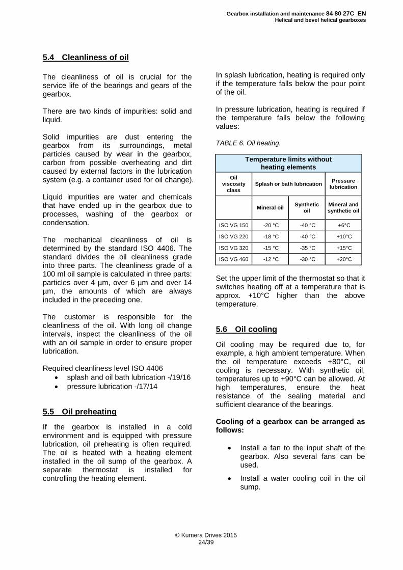
In splash lubrication, heating is required only if the temperature falls below the pour point of the oil. In pressure lubrication, heating is required if the temperature falls below the following values: TABLE 6. Oil heating.
Temperature limits without heating elements
Oil viscosity
class Splash or bath lubrication
Pressure lubrication
Mineral oil Synthetic
oil Mineral and synthetic oil
ISO VG 150 -20 °C -40 °C +6°C
ISO VG 220 -18 °C -40 °C +10°C
ISO VG 320 -15 °C -35 °C +15°C
ISO VG 460 -12 °C -30 °C +20°C
Set the upper limit of the thermostat so that it switches heating off at a temperature that is approx. +10°C higher than the above temperature.
5.6 Oil cooling Oil cooling may be required due to, for example, a high ambient temperature. When the oil temperature exceeds +80°C, oil cooling is necessary. With synthetic oil, temperatures up to +90°C can be allowed. At high temperatures, ensure the heat resistance of the sealing material and sufficient clearance of the bearings. Cooling of a gearbox can be arranged as follows:
Install a fan to the input shaft of the gearbox. Also several fans can be used.
Install a water cooling coil in the oil
sump.
Gearbox installation and maintenance 84 80 27C_EN
Helical and bevel helical gearboxes
© Kumera Drives 2015 25/39
Gearboxes with pressure lubrication can be cooled as follows:
Install a water-cooled heat exchanger into the oil circulating system.
Install an air-cooled heat exchanger into the oil circulating system.
For more details, see section 7.3.
5.7 Synthetic lubricants Synthetic lubricants can be used in gearboxes that are operating in very low or high temperatures and when the oil change interval should be extended. When using other than the synthetic lubricants specified below, check the suitability of the sealing materials.
5.8 Breather plug The breather plug is supplied detached. Install it when filling with oil. The breather plug must be replaced when the oil is changed. A clogged air filter generates pressure that causes oil leaks in the seals.
Gearbox installation and maintenance 84 80 27C_EN
Helical and bevel helical gearboxes
© Kumera Drives 2015 26/39
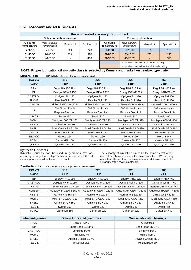
5.9 Recommended lubricants
Recommended viscosity for lubricant
Splash or bath lubrication Pressure lubrication
Oil sump temperature
Max. ambient temperature
Mineral oil Synthetic oil Oil sump
temperature Max. ambient temperature
Mineral oil Synthetic oil
< 60 °C < 25 °C 220 220 < 60 °C < 25 °C 150 150
61-80 °C 26-45 °C 320 320 61-80 °C 26-45 °C 220 220
81-95 °C 46-60 °C - 460 81-95 °C 46-60 °C - 320
Lubrication unit with additional cooling
Lubrication unit without additional cooling
NOTE. Proper lubrication oil viscosity class is selected by Kumera and marked on gearbox type plate.
Mineral oils DIN 51517-CLP, EP (extreme pressure) oil ISO VG 150 220 320 460
AGMA 4 EP 5 EP 6 EP 7 EP
ARAL Degol BG 150 Plus Degol BG 220 Plus Degol BG 320 Plus Degol BG 460 Plus
BP Energol GR-XP 150 Energol GR-XP 220 EnergolGR-XP 320 Energol GR-XP 460
CASTROL Optigear BM 150 Optigear BM 220 Optigear BM 320 Optigear BM 460
FUCHS Renolin CLP 150 Renolin CLP 220 Renolin CLP 320 Renolin CLP 460
KLÜBER Klüberoil GEM 1-150 N Klüberoi lGEM 1-220 N Klüberoil GEM 1-320 N Klüberoil GEM 1-460 N
LE 604 Almasol Vari- 607 Almasol Vari- 605 Almasol Vari- 608 Almasol Vari-
Purpose Gear Lub Purpose Gear Lub Purpose Gear Lub Purpose Gear Lub
LUKOIL Steelo 150 Steelo 220 Steelo 320 Steelo 460
MOBIL Mobilgear 600 XP 150 Mobilgear 600 XP 220 Mobilgear 600 XP 320 Mobilgear 600 XP 460
NESTE Vaihteisto 150 EP Vaihteisto 220 EP Vaihteisto 320 EP Vaihteisto 460 EP
SHELL Shell Omala S2 G 150 Shell Omala S2 G 220 Shell Omala S2 G 320 Shell Omala S2 G 460
TEBOIL Pressure Oil 150 Pressure Oil 220 Pressure Oil 320 Pressure Oil 460
TEXACO Meropa 150 Meropa 220 Meropa 320 Meropa 460
TOTAL Carter XEP 150 Carter XEP 220 Carter XEP 320 Carter XEP 460
Q8 OILS Q8 Goya NT 150 Q8 Goya NT 220 Q8 Goya NT 320 Q8 Goya NT 460 Synthetic lubricants Synthetic lubricants can be used in gearboxes that are operating in very low or high temperatures or when the oil change period should be longer than usual.
The viscosity of synthetic oil must be the same as that of the mineral oil otherwise used in the same conditions. When using other than the synthetic lubricants specified below, check the suitability of the sealing materials.
Synthetic oils DIN 51517-CLP, EP (extreme pressure) oil
ISO VG 150 220 320 460
AGMA 4 EP 5 EP 6 EP 7 EP
BP Enersyn HTX-150 Enersyn HTX-220 Enersyn HTX-320 Enersyn HTX-460
CASTROL Optigear synth X 150 Optigear synth X 220 Optigear synth X 320 Optigear synth X 460
FUCHS Renolin Unisyn CLP 150 Renolin Unisyn CLP 220 Renolin Unisyn CLP 320 Renolin Unisyn CLP 460
KLÜBER Klübersynth GEM 4-150 N Klübersynth GEM 4-220 N Klübersynth GEM 4-320 N Klübersynth GEM 4-460 N
NESTE Vaihteisto S 150 EP Vaihteisto S 220 EP Vaihteisto S 320 EP Vaihteisto S 460 EP
MOBIL Mobil SHC GEAR 150 Mobil SHC GEAR 220 Mobil SHC GEAR 320 Mobil SHC GEAR 460
SHELL Omala S4 GX 150 Omala S4 GX 220 Omala S4 GX 320 Omala S4 GX 460
TEBOIL Sypres 150 Sypres 220 Sypres 320 Sypres 460
TOTAL Carter SH 150 Carter SH 220 Carter SH 320 Carter SH 460
Lubricant greases Grease lubricated gearboxes Grease lubricated bearings
ARAL Aralub FDP 0 Aralub HL2
BP Energrease LS EP 0 Energrease LS EP 2
CASTROL Longtime PD 0 Longtime PD 2
MOBIL Mobilux EP 0 Mobilux EP 2
SHELL Alvania Grease GC 00 Alvania Grease RL 2
TEBOIL Universal CLS Multipurpose EP
Gearbox installation and maintenance 84 80 27C_EN
Helical and bevel helical gearboxes
© Kumera Drives 2015 27/39
6 Gearbox Design
6.1 Housing
The housings are made of grey cast iron. If necessary, nodular cast iron or a welded steel structure is used. The division planes of the housings are sealed with elastic compound.
6.2 Toothed parts
The helical teeth are case-hardened and ground, and calculated according to the standard ISO 6336. The bevel gears are case- hardened and lapped, and calculated according to the standard AGMA 2003-B97.
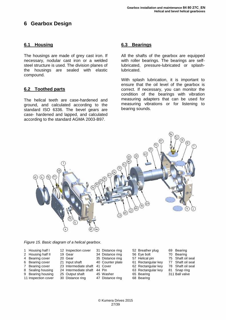
6.3 Bearings
All the shafts of the gearbox are equipped with roller bearings. The bearings are self-lubricated, pressure-lubricated or splash-lubricated. With splash lubrication, it is important to ensure that the oil level of the gearbox is correct. If necessary, you can monitor the condition of the bearings with vibration measuring adapters that can be used for measuring vibrations or for listening to bearing sounds.
Figure 15. Basic diagram of a helical gearbox. 1 Housing half I 2 Housing half II 4 Bearing cover 6 Bearing cover 7 Bearing cover 8 Sealing housing 9 Bearing housing 11 Inspection cover
12 Inspection cover 19 Gear 20 Gear 21 Input shaft 23 Intermediate shaft 24 Intermediate shaft 25 Output shaft 30 Distance ring
31 Distance ring 34 Distance ring 35 Distance ring 40 Counter plate 41 Cover 44 Pin 45 Washer 47 Distance ring
52 Breather plug 56 Eye bolt 57 Helical pin 61 Rectangular key 62 Rectangular key 63 Rectangular key 65 Bearing 68 Bearing
69 Bearing 70 Bearing 75 Shaft oil seal 77 Shaft oil seal 78 Shaft oil seal 81 Snap ring 311 Ball valve
Gearbox installation and maintenance 84 80 27C_EN
Helical and bevel helical gearboxes
© Kumera Drives 2015 28/39
6.4 Sealing
Ensure that the oil seals of the shafts are in good condition in order to prevent impurities from entering the bearing housing and lubricant. At the same time, this prevents lubricant from leaking from the gearbox. Try to prevent dirt from entering the seal. The shaft seals do not tolerate pressure washing.
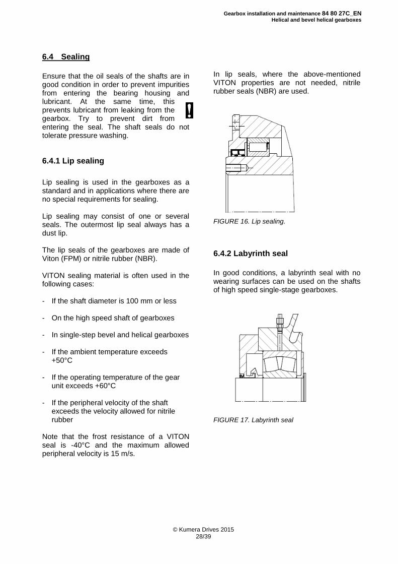
6.4.1 Lip sealing
Lip sealing is used in the gearboxes as a standard and in applications where there are no special requirements for sealing. Lip sealing may consist of one or several seals. The outermost lip seal always has a dust lip. The lip seals of the gearboxes are made of Viton (FPM) or nitrile rubber (NBR). VITON sealing material is often used in the following cases: - If the shaft diameter is 100 mm or less - On the high speed shaft of gearboxes - In single-step bevel and helical gearboxes - If the ambient temperature exceeds +50°C - If the operating temperature of the gear unit exceeds +60°C - If the peripheral velocity of the shaft exceeds the velocity allowed for nitrile rubber Note that the frost resistance of a VITON seal is -40°C and the maximum allowed peripheral velocity is 15 m/s.
In lip seals, where the above-mentioned VITON properties are not needed, nitrile rubber seals (NBR) are used.
FIGURE 16. Lip sealing.
6.4.2 Labyrinth seal
In good conditions, a labyrinth seal with no wearing surfaces can be used on the shafts of high speed single-stage gearboxes.
FIGURE 17. Labyrinth seal
Gearbox installation and maintenance 84 80 27C_EN
Helical and bevel helical gearboxes
© Kumera Drives 2015 29/39
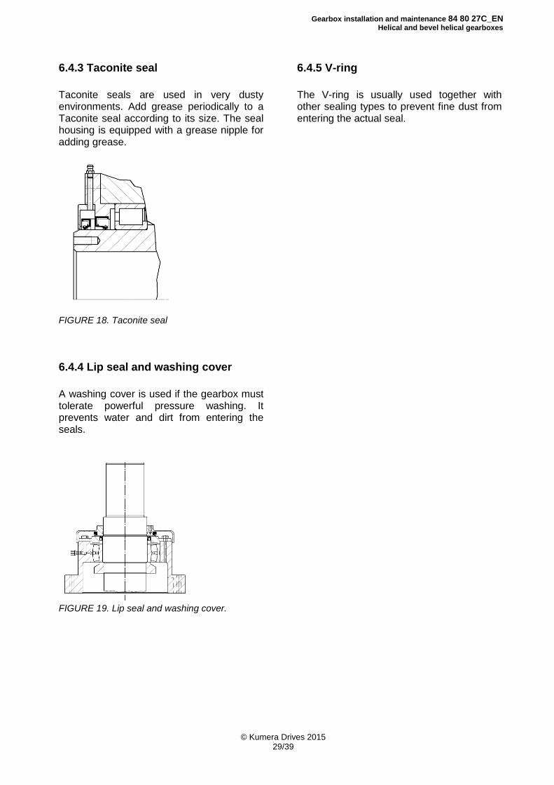
6.4.3 Taconite seal
Taconite seals are used in very dusty environments. Add grease periodically to a Taconite seal according to its size. The seal housing is equipped with a grease nipple for adding grease.
FIGURE 18. Taconite seal
6.4.4 Lip seal and washing cover
A washing cover is used if the gearbox must tolerate powerful pressure washing. It prevents water and dirt from entering the seals.
FIGURE 19. Lip seal and washing cover.
6.4.5 V-ring
The V-ring is usually used together with other sealing types to prevent fine dust from entering the actual seal.
Gearbox installation and maintenance 84 80 27C_EN
Helical and bevel helical gearboxes
© Kumera Drives 2015 30/39
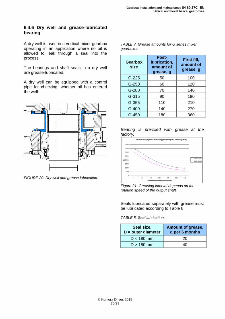
6.4.6 Dry well and grease-lubricated bearing
A dry well is used in a vertical-mixer gearbox operating in an application where no oil is allowed to leak through a seal into the process. The bearings and shaft seals in a dry well are grease-lubricated. A dry well can be equipped with a control pipe for checking, whether oil has entered the well.
FIGURE 20. Dry well and grease lubrication.
TABLE 7. Grease amounts for G series mixer gearboxes
Gearbox size
Post-lubrication, amount of grease, g
First fill, amount of grease, g
G-225 50 100
G-250 60 120
G-280 70 140
G-315 90 180
G-355 110 210
G-400 140 270
G-450 180 360
Bearing is pre-filled with grease at the factory.
Rasvausväli [h] / Toisioakselin pyörimisnopeus nopeus [r/min]
0
500
1000
1500
2000
2500
3000
3500
4000
5 50 100 150 200 250 300
Toisioakselin pyörimisnopeus [r/min]
[h] G225..G315
G355..G450
Figure 21. Greasing interval depends on the rotation speed of the output shaft.
Seals lubricated separately with grease must be lubricated according to Table 8. TABLE 8. Seal lubrication.
Seal size, D = outer diameter
Amount of grease, g per 6 months
D < 180 mm 20
D > 180 mm 40
Gearbox installation and maintenance 84 80 27C_EN
Helical and bevel helical gearboxes
© Kumera Drives 2015 31/39
7 Gearbox Accessories
7.1 Backstop
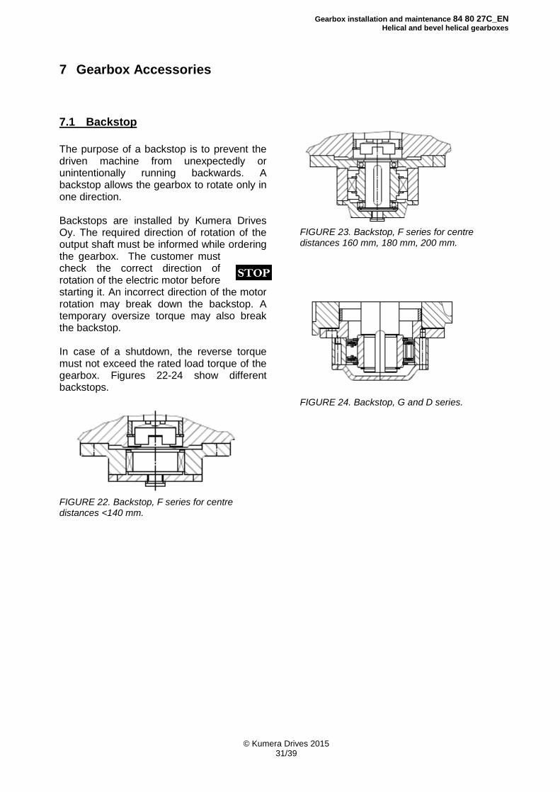
The purpose of a backstop is to prevent the driven machine from unexpectedly or unintentionally running backwards. A backstop allows the gearbox to rotate only in one direction. Backstops are installed by Kumera Drives Oy. The required direction of rotation of the output shaft must be informed while ordering the gearbox. The customer must check the correct direction of rotation of the electric motor before starting it. An incorrect direction of the motor rotation may break down the backstop. A temporary oversize torque may also break the backstop. In case of a shutdown, the reverse torque must not exceed the rated load torque of the gearbox. Figures 22-24 show different backstops.
FIGURE 22. Backstop, F series for centre distances <140 mm.
FIGURE 23. Backstop, F series for centre distances 160 mm, 180 mm, 200 mm.
FIGURE 24. Backstop, G and D series.
Gearbox installation and maintenance 84 80 27C_EN
Helical and bevel helical gearboxes
© Kumera Drives 2015 32/39
7.2 Lubrication pumps
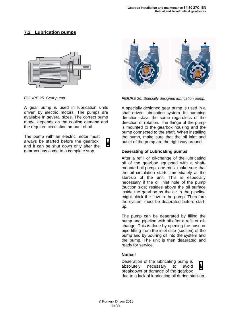
FIGURE 25. Gear pump.
A gear pump is used in lubrication units driven by electric motors. The pumps are available in several sizes. The correct pump model depends on the cooling demand and the required circulation amount of oil. The pump with an electric motor must always be started before the gearbox, and it can be shut down only after the gearbox has come to a complete stop.
FIGURE 26. Specially designed lubrication pump.
A specially designed gear pump is used in a shaft-driven lubrication system. Its pumping direction stays the same regardless of the direction of rotation. The flange of the pump is mounted to the gearbox housing and the pump connected to the shaft. When installing the pump, make sure that the oil inlet and outlet of the pump are the right way around. Deaerating of Lubricating pumps
After a refill or oil-change of the lubricating oil of the gearbox equipped with a shaft-mounted oil pump, one must make sure that the oil circulation starts immediately at the start-up of the unit. This is especially necessary if the oil inlet hole of the pump (suction side) resides above the oil surface inside the gearbox as the air in the pipeline might block the flow to the pump. Therefore the system must be deaerated before start-up. The pump can be deaerated by filling the pump and pipeline with oil after a refill or oil-change. This is done by opening the hose or pipe fitting from the inlet side (suction) of the pump and by pouring oil into the system and the pump. The unit is then deaerated and ready for service. Notice!
Deaeration of the lubricating pump is absolutely necessary to avoid breakdown or damage of the gearbox due to a lack of lubricating oil during start-up.
Gearbox installation and maintenance 84 80 27C_EN
Helical and bevel helical gearboxes
© Kumera Drives 2015 33/39
7.3 Pressure lubrication unit
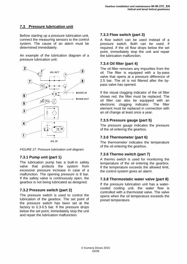
Before starting up a pressure lubrication unit, connect the measuring sensors to the control system. The cause of an alarm must be determined immediately. An example of the lubrication diagram of a pressure lubrication unit:
FIGURE 27. Pressure lubrication unit diagram.
7.3.1 Pump unit (part 1)
The lubrication pump has a built-in safety valve that protects the system from excessive pressure increase in case of a malfunction. The opening pressure is 8 bar. If the safety valve is continuously open, the gearbox is not being lubricated as designed.
7.3.2 Pressure switch (part 2)
The pressure switch is used to control the lubrication of the gearbox. The set point of the pressure switch has been set at the factory to 0.3-0.5 bar. If the pressure drops below the set point, immediately stop the unit and repair the lubrication malfunction.
7.3.3 Flow switch (part 3)
A flow switch can be used instead of a pressure switch. Both can be used, if required. If the oil flow drops below the set point, immediately stop the unit and repair the lubrication malfunction.
7.3.4 Oil filter (part 4)
The oil filter removes any impurities from the oil. The filter is equipped with a by-pass valve that opens at a pressure difference of 2.5 bar. The oil is not filtered after the by-pass valve has opened. If the visual clogging indicator of the oil filter shows red, the filter must be replaced. The oil filter can also be equipped with an electronic clogging indicator. The filter element must be replaced in connection with an oil change at least once a year.
7.3.5 Pressure gauge (part 5)
The pressure gauge indicates the pressure of the oil entering the gearbox.
7.3.6 Thermometer (part 6)
The thermometer indicates the temperature of the oil entering the gearbox.
7.3.6 Thermo switch (part 7)
A thermo switch is used for monitoring the temperature of the oil entering the gearbox. If the temperature exceeds the allowed limit, the control system gives an alarm.
7.3.8 Thermostatic water valve (part 8)
If the pressure lubrication unit has a water-cooled cooling unit, the water flow is controlled with a thermostat valve. The valve opens when the oil temperature exceeds the preset temperature.
Gearbox installation and maintenance 84 80 27C_EN
Helical and bevel helical gearboxes
© Kumera Drives 2015 34/39
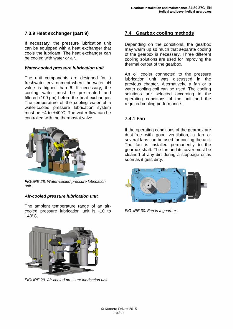
7.3.9 Heat exchanger (part 9)
If necessary, the pressure lubrication unit can be equipped with a heat exchanger that cools the lubricant. The heat exchanger can be cooled with water or air. Water-cooled pressure lubrication unit The unit components are designed for a freshwater environment where the water pH value is higher than 6. If necessary, the cooling water must be pre-treated and filtered (100 µm) before the heat exchanger. The temperature of the cooling water of a water-cooled pressure lubrication system
must be +4 to +40°C. The water flow can be
controlled with the thermostat valve.
FIGURE 28. Water-cooled pressure lubrication unit.
Air-cooled pressure lubrication unit The ambient temperature range of an air-cooled pressure lubrication unit is -10 to +40°C.
FIGURE 29. Air-cooled pressure lubrication unit.
7.4 Gearbox cooling methods
Depending on the conditions, the gearbox may warm up so much that separate cooling of the gearbox is necessary. Three different cooling solutions are used for improving the thermal output of the gearbox. An oil cooler connected to the pressure lubrication unit was discussed in the previous chapter. Alternatively, a fan or a water cooling coil can be used. The cooling solutions are selected according to the operating conditions of the unit and the required cooling performance.
7.4.1 Fan
If the operating conditions of the gearbox are dust-free with good ventilation, a fan or several fans can be used for cooling the unit. The fan is installed permanently to the gearbox shaft. The fan and its cover must be cleaned of any dirt during a stoppage or as soon as it gets dirty.
FIGURE 30. Fan in a gearbox.
Gearbox installation and maintenance 84 80 27C_EN
Helical and bevel helical gearboxes
© Kumera Drives 2015 35/39
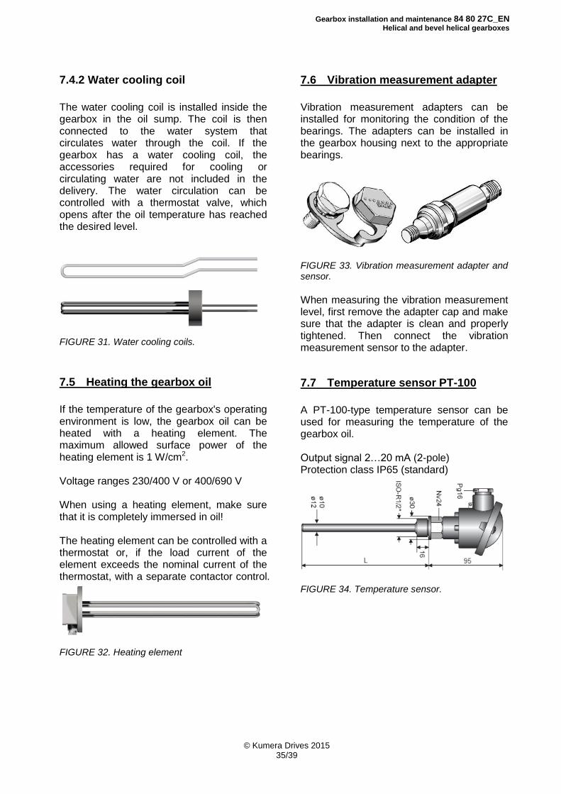
7.4.2 Water cooling coil
The water cooling coil is installed inside the gearbox in the oil sump. The coil is then connected to the water system that circulates water through the coil. If the gearbox has a water cooling coil, the accessories required for cooling or circulating water are not included in the delivery. The water circulation can be controlled with a thermostat valve, which opens after the oil temperature has reached the desired level.
FIGURE 31. Water cooling coils.
7.5 Heating the gearbox oil
If the temperature of the gearbox's operating environment is low, the gearbox oil can be heated with a heating element. The maximum allowed surface power of the heating element is 1 W/cm2. Voltage ranges 230/400 V or 400/690 V When using a heating element, make sure that it is completely immersed in oil! The heating element can be controlled with a thermostat or, if the load current of the element exceeds the nominal current of the thermostat, with a separate contactor control.
FIGURE 32. Heating element
7.6 Vibration measurement adapter
Vibration measurement adapters can be installed for monitoring the condition of the bearings. The adapters can be installed in the gearbox housing next to the appropriate bearings.
FIGURE 33. Vibration measurement adapter and sensor.
When measuring the vibration measurement level, first remove the adapter cap and make sure that the adapter is clean and properly tightened. Then connect the vibration measurement sensor to the adapter.
7.7 Temperature sensor PT-100
A PT-100-type temperature sensor can be used for measuring the temperature of the gearbox oil. Output signal 2…20 mA (2-pole) Protection class IP65 (standard)
FIGURE 34. Temperature sensor.
Gearbox installation and maintenance 84 80 27C_EN
Helical and bevel helical gearboxes
© Kumera Drives 2015 36/39
8 Scheduled Maintenance During an annual maintenance stop, the following maintenance and inspection procedures should be performed on the gearbox for determining its condition. In addition to the annual inspection, the gearbox’s operating sound, temperature and any leaks should be monitored daily. Any abnormalities must be corrected immediately.
Annual maintenance operations: 1. Oil change and inspection
Oil must be changed every year (mineral oil) or every two years (synthetic oil).
When changing the oil, check its condition to see whether the change interval is suitable for the application.
The condition of the oil can be checked visually and based on the smell. Deteriorated oil has become dark and smells pungent.
The condition of the oil can also be determined with a laboratory test, based on which a suitable change interval can be determined.
When opening the inspection covers of the gearbox clean the sealing surfaces carefully and spread new sealing compound on the sealing surfaces before closing the covers.
2. Replacing the breather plug
The breather plug must be replaced when the oil is changed
3. Inspecting the teeth
Visually via the inspection cover
4. Inspecting possible leakages and lubrication equipment
Inspect the shaft seals
Check the tightness of the joint surfaces and, if required, the tightness of the screws and pipe connections
Inspect the oil tightness of the pump
Inspect the tightness of the oil cooler
Replace the oil filter
5. Cleaning the fan
If the gearbox has a fan, it must be cleaned.
Gearbox installation and maintenance 84 80 27C_EN
Helical and bevel helical gearboxes
© Kumera Drives 2015 37/39
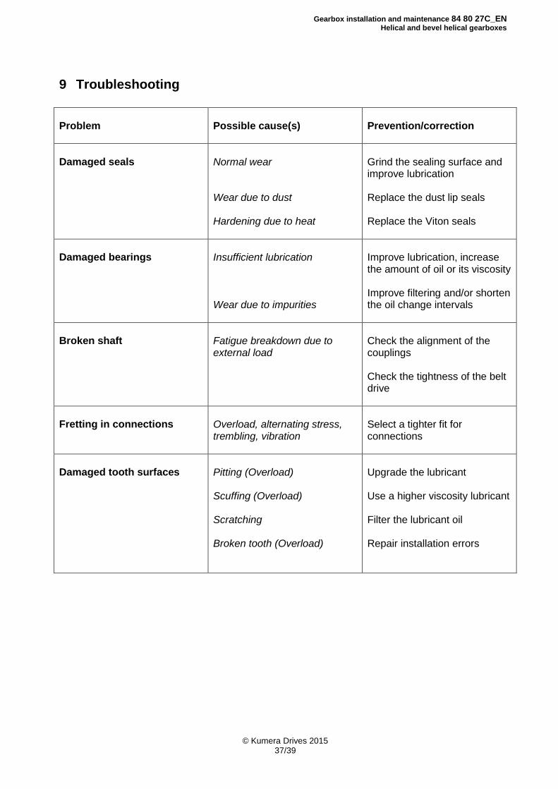
9 Troubleshooting
Problem
Possible cause(s)
Prevention/correction
Damaged seals
Normal wear Wear due to dust Hardening due to heat
Grind the sealing surface and improve lubrication Replace the dust lip seals Replace the Viton seals
Damaged bearings
Insufficient lubrication Wear due to impurities
Improve lubrication, increase the amount of oil or its viscosity Improve filtering and/or shorten the oil change intervals
Broken shaft
Fatigue breakdown due to external load
Check the alignment of the couplings Check the tightness of the belt drive
Fretting in connections
Overload, alternating stress, trembling, vibration
Select a tighter fit for connections
Damaged tooth surfaces
Pitting (Overload) Scuffing (Overload) Scratching Broken tooth (Overload)
Upgrade the lubricant Use a higher viscosity lubricant Filter the lubricant oil Repair installation errors

Gearbox installation and maintenance 84 80 27C_EN
Helical and bevel helical gearboxes
© Kumera Drives 2015 38/39
NOTES

Gearbox installation and maintenance 84 80 27C_EN
Helical and bevel helical gearboxes
© Kumera Drives 2015 39/39
NOTES

KUMERA DRIVES OY Kumerankatu 2
FI-11100 RIIHIMÄKI, FINLAND Tel. +358 20 755 4200 Fax: +358 20 755 4220
E-mail: [email protected]
www.kumera.com www.power-plaza.com