INSTALLATION AND HANDLING INSTRUCTIONS - … INC. LANCER EVOLUTION X SUPER TRACTION REAR L.S.D....
14
RALLIART INC. LANCER EVOLUTION X SUPER TRACTION REAR L.S.D. ASSEMBLY RA166619K1 INSTALLATION AND HANDLING INSTRUCTIONS R023-0279-0803 Thank you for purchasing the RALLIART product. Read this publication carefully to ensure correct installation and use of the product with proper knowledge of it. Keep this publication near at hand for reference when maintenance is required. Attention ● The following symbols are used in this publication for your particular attention. ● Failure to follow instructions given in this publication during installation not only prevents the product from working as it should but may lead to trouble with the vehicle. Be sure to follow all given instructions and install the product properly. ● RALLIART is not responsible for any defects or difficulties caused by or resulting from the installation of this product. ● Defects that may be directly or indirectly caused to the vehicle equipped with this product are NOT covered in any way by Mitsubishi Motors Corporation’s warranty for its product. To the dealer ● Be sure that the customer receives this publication. To the customer ● Read handling instructions carefully before use. ● Keep this publication neat at hand (in the glove compartment, for example) for reference in case of need. are particularly important precautions to ensure safety in the installation and handling of the product. Warning · · · Precautions to be observed for safety. Failure to follow given instructions could lead to serious injury or death. Caution · · · Precautions to be observed for safety. Failure to follow given instructions could lead to injury or accident. Advice · · · Instructions to be followed for proper installation. Warning Caution and
Transcript of INSTALLATION AND HANDLING INSTRUCTIONS - … INC. LANCER EVOLUTION X SUPER TRACTION REAR L.S.D....

RALLIART INC.
LANCER EVOLUTION X SUPER TRACTION REAR L.S.D.
ASSEMBLY RA166619K1
INSTALLATION AND HANDLING INSTRUCTIONS
R023-0279-0803
Thank you for purchasing the RALLIART product. Read this publication carefully to ensure correct installation and use of the product with proper knowledge of it. Keep this publication near at hand for reference when maintenance is required.
Attention ● The following symbols are used in this publication for your particular attention. ● Failure to follow instructions given in this publication during installation not only prevents the product
from working as it should but may lead to trouble with the vehicle. Be sure to follow all given instructions and install the product properly.
● RALLIART is not responsible for any defects or difficulties caused by or resulting from the installation
of this product. ● Defects that may be directly or indirectly caused to the vehicle equipped with this product are NOT
covered in any way by Mitsubishi Motors Corporation’s warranty for its product.
To the dealer ● Be sure that the customer receives this publication.
To the customer ● Read handling instructions carefully before use. ● Keep this publication neat at hand (in the glove compartment, for
example) for reference in case of need.
are particularly important precautions to ensure safety in the installation and handling of the product.
Warning · · · Precautions to be observed for safety. Failure to follow given instructions could lead to serious injury or death.
Caution · · · Precautions to be observed for safety. Failure to follow given instructions could lead to injury or accident.
Advice · · · Instructions to be followed for proper installation.
Warning Caution and

RALLIART INC.
Precautions for Installation
Special Tools (Make the following tools ready for use.)
R023-0279-08031
To the Customer
Handling Instructions
Applicable Model Model name Type Classification T/M Part No.
LANCER EVOLUTION X (RS) CZ4A SNDFZ 5FM/T RA166619K1 * This product cannot be installed to the vehicle with S-AYC.
1. Do not use this product for any other purposes than intended. 2. Do not modify this product in any way. 3. Never use or install this product on any other vehicle than specified. Otherwise, damage or accident could be
caused. 4. This product cannot be installed in combination with any other product. Be sure to use it in the kit. 5. Check the vehicle as required to ensure that this product is always in normal condition including the installed
state. 6. After this product is installed, when the vehicle develops any abnormality during driving, stop it immediately
and have it checked, and repaired as necessary, at an appropriate service shop. Otherwise damage to the vehicle or accident may result.
7. If this product fails to function as it should due to deterioration, damage or for any other reason, replace it without delay.
8. Being a mechanical (multi-disc) type L.S.D., this product may cause squeals of driving wheels and chattering noises of gears in the differential during normal cornering.
9. Depending on measuring conditions, data shown in this publication may be found different from measured values.
10. This product is designed for competition use. This product may deteriorate sooner than its standard counterpart.
11. When participating in a competition with this product installed, it is the entrant’s responsibility to confirm that the installation of this product conforms to the technical rules of the competition.
Caution
1. To ensure safety, always turn the ignition switch to OFF and apply the parking brake securely. 2. When jacking up, make sure that the vehicle is firmly supported with rigid racks. 3. To avoid possible deformation, be sure to apply rigid racks to the vehicle at designated places. 4. Be careful not to damage the front under cover and rear differential carrier assembly.
Bearing puller Bearing inner race installer (MB990728 or equivalent)
5. This publication only describes the main points in installation work. For specific installation procedures,
backlash adjustment, etc., refer to the relevant workshop manual issued by Mitsubishi Motors Corporation. 6. Be sure to tighten the fasteners to their specified torques.
Advice
Caution

RALLIART INC.
Components (Make sure that all of the following components were included in the kit.)
Required Parts (Necessary for installation)
R023-0279-08032
(1) Super traction rear L.S.D.: 1
Mitsubishi genuine parts
Differential side bearing (MB393957): 2 Spacer set (MR357058): 1 set
RALLIART INC.
Installation Procedures
R023-0279-08033
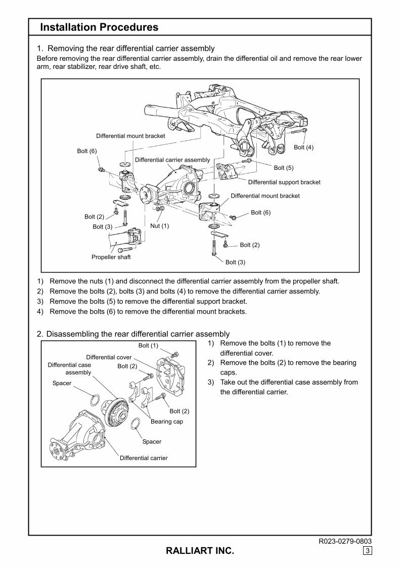
1. Removing the rear differential carrier assembly Before removing the rear differential carrier assembly, drain the differential oil and remove the rear lower arm, rear stabilizer, rear drive shaft, etc. 1) Remove the nuts (1) and disconnect the differential carrier assembly from the propeller shaft. 2) Remove the bolts (2), bolts (3) and bolts (4) to remove the differential carrier assembly. 3) Remove the bolts (5) to remove the differential support bracket. 4) Remove the bolts (6) to remove the differential mount brackets.
1) Remove the bolts (1) to remove the differential cover.
2) Remove the bolts (2) to remove the bearing caps.
3) Take out the differential case assembly from the differential carrier.
Differential mount bracket
Bolt (4)
Bolt (5)
Bolt (6) Differential carrier assembly
Differential support bracket
Bolt (2) Bolt (3) Nut (1)
Differential mount bracket
Bolt (6)
Propeller shaft
Bolt (2)
Bolt (3)
Differential cover
Bolt (1)
Bolt (2)
Bolt (2)
Spacer
Bearing cap
Differential carrier
Spacer
Differential case assembly
2. Disassembling the rear differential carrier assembly

RALLIART INC.
Installation Procedures
R023-0279-08034
4) Remove the bolts (3). Remove the drive gear from the differential case assembly by tapping the gear with a plastic hammer.
1) Remove residual adhesive from the bolt holes
in the drive gear using a tap, then clear the holes with compressed air.
2) Apply anaerobic adhesive into the bolt holes in the drive gear and install the drive gear to the L.S.D. assembly by tightening the bolts (3) to the specified torque.
3) Using the special tool, press-fit the differential
side bearing inner race to the L.S.D. assembly.
Keep the removed drive gear and bolts (3) as they will be reused.
Advice
Drive gear
Bolt (3)
3. Installing the drive gear to the super traction rear L.S.D. assembly
Drive gear
Bolt (3)
L.S.D. assembly
Metal plate
Metal plate
MB990728 or equivalent
● Tightening torque
Bolt (3): 84 ± 4 N·m ● Anaerobic adhesive
Three Bond 1303, Loctite 648, or equivalent
Advice

RALLIART INC.
Installation Procedures
R023-0279-08035
1) Fit the side bearing outer race to the L.S.D.
assembly. Select appropriate backlash adjusting spacers in accordance with the procedure in the workshop manual issued by Mitsubishi Motors and fit them to the L.S.D. assembly. Then, install the L.S.D. assembly in the differential carrier.
2) Align the alignment marks on the bearing
caps and the differential carrier, secure them with the bolts (1).
3) With an uniform bead of semi-dry sealant
applied to its entire periphery as shown, attach the differential cover to the carrier case and secure them together with the bolts (2).
5. Reinstalling the rear differential carrier assembly
1) Reinstall the rear differential carrier assembly to the vehicle in the reverse sequence of removal.
4. Assembling the rear differential carrier assembly
2 - 3 mm (bead width) Bolt (2)
Bolt (1)
Differential cover
Bearing cap
Spacer
Spacer
L.S.D. assembly Carrier case
Bolt (6)
Differential mount bracket
Bolt (4)
Differential carrier assembly
Differential support bracket
Bolt (5)
Bolt (2) Bolt (3)
Bolt (6)
Differential mount bracket
Bolt (2)
Bolt (3) Propeller shaft
Nut (1)
● Tightening torque
Bolt (1): 37 ± 2 N·m Bolt (2): 48 ± 6 N·m
● Recommended sealant: ThreeBond 1216 or equivalent
Advice
● Tightening torque Nut (1): 54 ± 5 N·m Bolt (3): 110 ± 11 N·m Bolt (5): 95 ± 14 N·m Bolt (2): 11 ± 3 N·m Bolt (4): 110 ± 11 N·m Bolt (6): 95 ± 14 N·m Bolt (4) is applied with friction factor stabilizer. Check the bolt for scratches, remove dust and dirt from its bearing surface and threads, and tighten it firmly to the specified torque.
Advice

RALLIART INC.
Installation Procedures
Supplementary Instructions
R023-0279-08036
2) Fill the specified gear oil up to the lower edge of the filler plug hole of the differential carrier assembly as shown. Install the filler plug and tighten it to the specified torque.
Oil Replacement Interval after Installing This Product
Item Interval Quantity (dm3) Specified Oil Differential oil Every 20,000 km 0.55 Mitsubishi genuine DiaQueen LSD gear oil
Gear oil
● Specified gear oil:
Mitsubishi genuine DiaQueen LSD gear oil
● Tightening torque Filler plug: 49 ± 9 N·m (5.0 kgfm)
Advice
MEMO
● This oil replacement interval is a rough estimate. Depending on the operating condition, the oil
may deteriorate more quickly. To be on the safe side, earlier change is recommended.
Advice

RALLIART INC.
LANCER EVOLUTION X SUPER TRACTION REAR L.S.D.
ASSEMBLY
OVERHAUL INSTRUCTIONS
Thank you for purchasing the RALLIART product. Read this publication carefully to ensure correct overhauling of the product with proper knowledge of it. Keep this publication near at hand for reference when maintenance is required.
Attention ● The following symbols are used in this publication for your particular attention. ● Failure to follow instructions given in this publication during installation not only prevents the product
from working as it should but may lead to trouble with the vehicle. Be sure to follow all given instructions and install the product properly.
● RALLIART is not responsible for any defects or difficulties caused by or resulting from the installation
of this product. ● Defects that may be directly or indirectly caused to the vehicle equipped with this product are NOT
covered in any way by Mitsubishi Motors Corporation’s warranty for its product.
To the dealer ● Be sure that the customer receives this publication.
To the customer ● Read handling instructions carefully before use. ● Keep this publication neat at hand (in the glove compartment, for
example) for reference in case of need.
Warning · · · Precautions to be observed for safety. Failure to follow given instructions could lead to serious injury or death.
Caution · · · Precautions to be observed for safety. Failure to follow given instructions could lead to injury or accident.
Advice · · · Instructions to be followed for proper installation.
are particularly important precautions to ensure safety in the installation and handling of the product.
Warning Caution and

RALLIART INC. 1
To the Customer
Handling Instructions
Applicable Model Model name Type Classification T/M Part No.
LANCER EVOLUTION X (RS) CZ4A SNDFZ 5FM/T RA166619K1
1. Do not use this product for any other purposes than intended. 2. Do not modify this product in any way. 3. Never use or install this product on any other vehicle than specified. Otherwise, damage or accident could be
caused. 4. This product cannot be installed in combination with any other product. Be sure to use it in the kit. 5. Check the vehicle as required to ensure that this product is always in normal condition including the installed
state. 6. After this product is installed, when the vehicle develops any abnormality during driving, stop it immediately
and have it checked, and repaired as necessary, at an appropriate service shop. Otherwise damage to the vehicle or accident may result.
7. If this product fails to function as it should due to deterioration, damage or for any other reason, replace it without delay.
8. Being a mechanical (multi-disc) type L.S.D., this product may cause squeals of driving wheels and chattering noises of gears in the differential during normal cornering.
9. Depending on measuring conditions, data shown in this publication may be found different from measured values.
10. This product is designed for competition use. This product may deteriorate sooner than its standard counterpart.
11. When participating in a competition with this product installed, it is the entrant’s responsibility to confirm that the installation of this product conforms to the technical rules of the competition.
Caution

RALLIART INC.
Information
2
[Component Parts of Rear L.S.D. Assembly]
[Installation Condition of Rear L.S.D Assembly] 1. Assembling sequence and direction of friction discs and plates
No. Part name Q’ty Service parts availability
Remarks
1 Case A 1 ——
2 Case B 1 ——
3 Side gear 2 ——
4 Pinion gear 4 ——
5 Pinion shaft 1 ——
6 Friction plate 10 Ο Outer pawl
7 Friction disc 10 Ο Inner pawl
8 Cam ring set 1 Ο 55°/35° – 55°/55°
9 Cone spring 2 Ο T=1.8 mm
10 Bolt 4 —— Tightening torque: 14.7 N·m
Case A (1)
Cone spring (9)
Case B (2) Bolt (10)
Friction disc (7)
Pinion gear (4)
Friction disc (7)
Friction plate (6)
Friction plate (6)
Side gear (3)
Cam ring (8)
Pinion shaft (5) Side gear (3)
Cam ring (8)
Case A Friction plate Case B
Driving side
Cam ring Friction disc
Cone spring Cone spring
Coasting side
● Subsequent explanations are based on the assembling sequence and direction shown above.
Advice
RALLIART INC.
Information
3
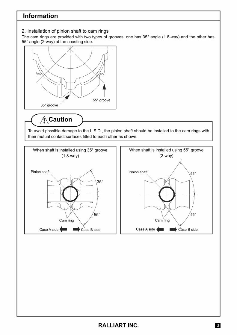
2. Installation of pinion shaft to cam rings The cam rings are provided with two types of grooves: one has 35° angle (1.8-way) and the other has 55° angle (2-way) at the coasting side.
When shaft is installed using 35° groove (1.8-way)
When shaft is installed using 55° groove (2-way)
55° groove 35° groove
To avoid possible damage to the L.S.D., the pinion shaft should be installed to the cam rings with their mutual contact surfaces fitted to each other as shown.
Caution
Pinion shaft
Cam ring
Case A side Case B side
35°
55°
Case A side Case B side
Cam ring
Pinion shaft 55°
55°
RALLIART INC.
Information
4
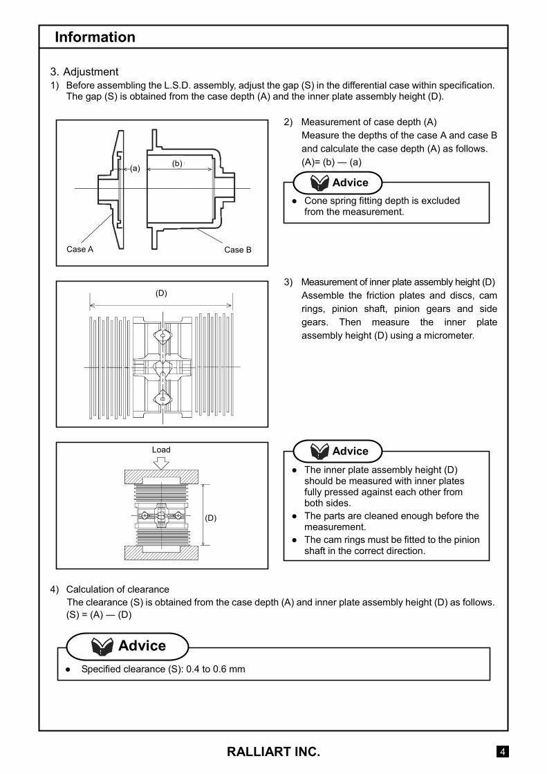
3. Adjustment 1) Before assembling the L.S.D. assembly, adjust the gap (S) in the differential case within specification.
The gap (S) is obtained from the case depth (A) and the inner plate assembly height (D).
2) Measurement of case depth (A) Measure the depths of the case A and case B and calculate the case depth (A) as follows. (A)= (b) ― (a)
3) Measurement of inner plate assembly height (D)
Assemble the friction plates and discs, cam rings, pinion shaft, pinion gears and side gears. Then measure the inner plate assembly height (D) using a micrometer.
4) Calculation of clearance The clearance (S) is obtained from the case depth (A) and inner plate assembly height (D) as follows. (S) = (A) ― (D)
Case A Case B
● Cone spring fitting depth is excluded
from the measurement.
Advice
● The inner plate assembly height (D)
should be measured with inner plates fully pressed against each other from both sides.
● The parts are cleaned enough before the measurement.
● The cam rings must be fitted to the pinion shaft in the correct direction.
Advice
● Specified clearance (S): 0.4 to 0.6 mm
Advice
(a) (b)
(D)
Load
(D)

RALLIART INC.
Information
5
5) Adjustment of clearance If the clearance is out of specification, select the friction plates of appropriate thicknesses and adjust the clearance within the standard value.
4. Reassembling the l.s.d. assembly
Reassemble the L.S.D. assembly.
5. Cam angle and initial torque at the time of delivery
Cam angle Initial torque 55°/55°
(Driving side/coasting side) Approx. 120 N·m
Friction plate Friction disc
* The initial torque given above is the value when mounted on the vehicle. If measured as shown in the drawing, the value should be a half of the above.
● Friction plate thickness
RACZ4203K1: 1.6 mm RACZ4203K2: 1.8 mm
● Friction disc thickness RACZ4202K1: 1.6 mm
Advice
● Bolt tightening torque: 14.7 N·m
Advice

RALLIART INC.
Information
6
[Service Parts]
No. Part name RALLIART part No. Remarks 1 Rear L.S.D. assembly RA166619K1 55°/55° – 55°/35° 2 Cam ring set (set of LH and RH cam rings) RACZ4205S1 55°/55° – 55°/35° 3 Friction disc RACZ4202K1 Inner pawl (T = 1.6 mm)
RACZ4203K1 Outer pawl (T = 1.6 mm) 4 Friction plate
RACZ4203K2 Outer pawl (T = 1.8 mm) 5 Cone spring RACZ4204K1 T = 1.8 mm
Rear L.S.D. assembly (1)
Friction plate (4)
Cone spring (5)
Cam ring set (2)
Friction disc (3) Cone spring (5)