INSTALLATION MANUAL...installation manual ekcbx008bbv3 ekcbh008bbv3

InstallatIon and EngInEErIng Manual

Pre-Construction Details ............................... 3Safety ...................................................................................................3.Drainage ............................................................................................3.Base Pad ............................................................................................3.Disclaimer .........................................................................................3.
Block Specifications....................................... 3Block Specifications ...................................................................4
Lifting Methods ............................................. 6Lifting Loops ...................................................................................6Lift Anchors .....................................................................................6Rebar ...................................................................................................6
Installation Basics .......................................... 7Wall Stability ...................................................................................7Setting Into Hills ...........................................................................7
Corners ........................................................... 8Outside Corner ..............................................................................8Inside Corner ..................................................................................8
Key Blocks ...................................................... 9Straight Walls ...............................................10
Inside-Outside ............................................................................10Outside-Outside ........................................................................10Inside-Inside ................................................................................11
Full Circles ....................................................12Curves ...........................................................13Inside Curves ................................................14
Inside-Outside ............................................................................14Outside –Outside .....................................................................14Inside-Inside ................................................................................15
Outside Curves .............................................16Inside-Outside ............................................................................16Outside-Outside ........................................................................16Inside-Inside ................................................................................17
Geogrid .........................................................18Installation ....................................................................................18Corners ............................................................................................18Curves ..............................................................................................19
Base Blocks ...................................................20Steps .............................................................21Fencing .........................................................22Terracing.......................................................23Seawalls ........................................................23Finishing off your wall .................................24
Recess Blocks ..............................................................................24Top Caps ........................................................................................25
Product Specification Guide .......................26Part 1: General .............................................26
1.1 Section Includes ................................................................261.2 Related Requirements ...................................................261.3. Reference Standards .......................................................261.4 Preinstallation Meetings ...............................................271.5 Submittals .............................................................................281.6 Quality Assurance .............................................................281.7 Delivery, Storage, and Handling ..............................28
Part 2: Products ...........................................292.1 Design Criteria ....................................................................292.2 Concrete Landscape Blocks .......................................292.3. Soil .............................................................................................3.12.4 Geogrid Soil Reinforcement ......................................3.12.5 Geotextile Filter Fabric ...................................................3.3.2.6 Drainage collection Pipe ..............................................3.4
Part 3: Execution ..........................................343..1 Examination .........................................................................3.43..2 General ....................................................................................3.43..3. Excavation .............................................................................3.43..4 Base Leveling Pad .............................................................3.53..5 Concrete Landscape Block Installation ...............3.53..6 Geotextile Filter Fabric ...................................................3.53..7 Geogrid Soil Reinforcement Installation ............3.53..8 Reinforced Backfill Placement ..................................3.63..9 Tolerances..............................................................................3.63..10 Field Quality Control ....................................................3.73..11 Protection ...........................................................................3.7
Table of ConTenTs
2 W O R L D B L O C k
InSTALLATIOn AnD EnGInEERInG MAnuAL

Before construction, a few details must be planned to ensure safe construction.
SafetyWorld Block’s number one goal is always user safety both during construction and thereafter. Always fol-low all local, state and federal building codes during installation. In addition, a Professional Engineer (P.E.) must be placed in charge of design for every World Block project. Follow all site specific considerations your engineer specifies.
DrainageThe presence of water around a retaining wall can dramatically reduce the abilities of your wall. It is crucial to take into account the presence of any water behind your wall, and provide adequate drainage for it. This is the job for your Professional Engineer. Reference the Product Specification Guide, Section 2.6 on page 3.4.
BaSe PaDA solid wall starts with a solid foundation. Building your wall on an unsuitable base will likely have drastic consequences. See sections 2.3. and 3..4 of the Product Specification Guide on pages 3.1 and 3.5 respec-tively.
DiSclaimerThese drawings have been prepared by World Block, Inc. The design is for internal stability of World Block structures only. External stability, including, but not limited to, foundation and slope stability is the respon-sibility of the owner. These designs are based on the assumption of proper installation by World Block specifications.
To the best of our knowledge, these drawings accurately represent product use in the applications shown. These drawings are to be used for conceptual, instructional, and estimating purposes only. Anyone using these drawings does so at their own risk and assumes all liability for such use. Final construction design must be performed by a registered Professional Engineer who is familiar with the product and who has taken into account the specific site conditions.
Pre-ConsTruCTion DeTails
3W W W . W O R L D B L O C k . C O M

bloCk sPeCifiCaTions
4 W O R L D B L O C k
InSTALLATIOn AnD EnGInEERInG MAnuAL

bloCk sPeCifiCaTions
5W W W . W O R L D B L O C k . C O M

lifting looPSLifting Loops are made of 3./8” stranded cable and make for an excellent way to lift your blocks. The Lifting Loop Block-out, made of urethane, creates a recessed void where your Loop will stick out. Before pouring your block, insert a Loop into the Blockout securely. After pouring, keep your Block-out bolted to the form while stripping. Remaining will be a recessed void containing your liftpoint.
lift anchorSAnother option for lifting your blocks is to use Lift Anchors. Landscape Lift Anchors are 9 ¾” and zinc plated. Lift Anchors are used with Lift Anchor Blockouts. Before pouring, place a Lift Anchor into the Blockout securely. When you’re ready to strip the form, keep the Blockout bolted into the form. Your block will then have a recessed void containing your Lift An-chor. For Anchors, you’ll need to have a Lift Clutch on hand to move your blocks.
reBarOne more option for moving your blocks is to use rebar. Be-fore pouring your block, bend a piece of rebar and place the radius into a Rebar Liftpoint Blockout. When you’re ready to strip your form, be certain to unbolt the Blockout before you strip the form. If not, the Blockout will be ruined.
lifting methoDSWorld Block offers three systems for lifting your blocks and putting them into place- loops, anchors and rebar.
6 W O R L D B L O C k
InSTALLATIOn AnD EnGInEERInG MAnuAL

inStallation BaSicS
Wall StaBilityTo protect against tipping, World Block walls require each course to step back 2 inches. World Blocks are designed with this in mind having the bottom trough offset two inches from the top knobs. This 2 inch step back is a critical design feature that must be featured in every World Block project.
Setting into hillSWhen setting your blocks into a hill, remember to keep a good base underneath all your blocks. A few blocks will barely be visible, but are critical to the wall’s stability.
7W W W . W O R L D B L O C k . C O M

cornerSThere are two different types of corners you can build with World Blocks- inside corners and out-side corners. Each is made differently, using different blocks.
outSiDe cornerThe outside corner is made by alternating Left and Right Outside Corner Blocks on each successive course. Remem-ber that each Corner Block will be placed back 2 inches in both directions to account for the wall’s setback.
inSiDe cornerTo make an inside corner, you’ll need an Inside Corner Blockout, and a Rubber knob Blockout. Because of the geometry of inside corners, the inside knob of each corner block must be blocked out (except on the top course). To compensate, use construction ad-hesive to lock the block in place. Overlap one Left or Right Inside Corner Block successively on each course to make the corner.
8 W O R L D B L O C k
InSTALLATIOn AnD EnGInEERInG MAnuAL

Key BlocKSkey Blocks are 44 inches long- 4 inches shorter than the standard Landscape Block. These are used to account for a change in course length due to your wall’s features, i.e. corners and curves. The amount and placement of key Blocks you need depends on what features your wall has. Each situation is different, and is explained in detail throughout this manual.
notes:
9W W W . W O R L D B L O C k . C O M

Straight WallSA straight wall is built differently based upon what corner pairings you use- two inside corners, two outside corners, or one of each.
inSiDe-outSiDeThe inside-outside is the easiest corner pairing to build, because there is no need to use key Blocks in the wall. Simply use your standard Landscape Blocks, combined with Inside and Outside Corner Blocks, to create your wall. Remember that each course must step back 2 inches.
outSiDe-outSiDeThe outside corner on either side of the outside-outside corner pairing steps in 2 inches to adjust for the wall running in the other direction. As a result your wall gets squeezed in 4 inches on every course going up. Correcting this problem requires the use of key Blocks. The bottom layer does not require a key Block; however, as you build up, each successive course will require one additional key Block. Your second row will require 1 key Block, your third row 2, and so on. At 12 courses the wall is squeezed 48 inches and does not require a key Block- then simply start the pattern over again.
10 W O R L D B L O C k
InSTALLATIOn AnD EnGInEERInG MAnuAL

inSiDe-inSiDeThe inside-inside corner pairing is similar to the outside-outside, but is, in a way, opposite. The inside corner on either side steps out 2 inches to adjust for the wall running in the other direction. As a result, your wall gets squeezed in 4 inches on every course going down. This problem, again, requires the use of key Blocks. The top layer of your wall will not require a key Block. However, each successive layer down will require one additional key Block. For this reason, a precise plan of the wall must be fashioned before construction.
notes:
11W W W . W O R L D B L O C k . C O M

full circleSUsing Tapered End Inserts allows your World Blocks to create a perfect circle. The tightest circle you can make with standard Landscape Blocks will have an outside radius of 16 feet, and an inside radius of 14 feet. Notice that if you’re stacking several courses of full circles, the top course must be designed with the smallest diameter. Of course, larger diameters can be made by simply using more blocks in your circle.
12 W O R L D B L O C k
InSTALLATIOn AnD EnGInEERInG MAnuAL

curveSCurves present design challenges not found in straight walls. This is because of the changing ra-dius of curves, regardless of the corner pairing. The easiest way to prevent problems is to have one or two free ends on your curve to allow the change in length of each course.
notes:
13W W W . W O R L D B L O C k . C O M

inSiDe curveSBecause each course steps back 2 inches, the radius of an inside curve becomes larger. This makes the length of each successive course slightly larger. This will leave a gap at the end of the course. Due to the nature of curves, this change in length is very unpredictable.
inSiDe-outSiDeFor straight walls, inside-outside corner pairings do not require the use of key Blocks. However, when building a curve, the wall length changes because of the change in radius. This means key Blocks will have to be introduced into the wall. The bottom of the wall will have the most key Blocks, and less will be required moving up. Exactly how many key Blocks will be needed is unpredictable and is different for every wall.
outSiDe-outSiDeThe outside-outside corner pairing is built quite differently than the inside-outside. Since both corners are outside corners, there is a need for key Blocks as you proceed up a wall. However, because of the changing radius of each successive layer, there is unpredictability in how many key Blocks will be needed.
14 W O R L D B L O C k
InSTALLATIOn AnD EnGInEERInG MAnuAL

inSiDe-inSiDeThe inside-inside corner pairing is similar to the inside-outside corner pairing, as it requires more key Blocks as you go down the wall. The inside-inside corner pairing is different, however, in that both the curvature of the wall and the corner insteps squeeze the wall in. Therefore, many key Blocks will be used in the curve. For this reason a precise plan of the wall must be fashioned before construction.
notes:
15W W W . W O R L D B L O C k . C O M

outSiDe curveSSimilar to inside curves, outside curves have the potential for many design problems. This is be-cause of the changing radius of curves, regardless of the corner pairing. Dissimilar to inside curves, when each course steps back 2 inches the radius of your curve becomes smaller. This makes the length of each successive course slightly smaller. Due to the nature of curves, this change in length is very unpredictable.
inSiDe-outSiDeThe bottom course of an inside-outside outside curve will require no key Blocks. However, as the wall is built higher it begins to get squeezed, so key Block must be introduced. Due to the nature of changing radii, exactly how many key Blocks is unpre-dictable and differs on a case to case basis.
outSiDe-outSiDeThe outside-outside corner pairing uses the most key Blocks of any outside curve corner pairing. Since the courses are squeezed both by changing radii and the corners, the wall will require many key Blocks. The bottom layer will not require any key Blocks, but you’ll have to use more as the wall goes up. The exact number is unpredictable because of the changing radii.
16 W O R L D B L O C k
InSTALLATIOn AnD EnGInEERInG MAnuAL
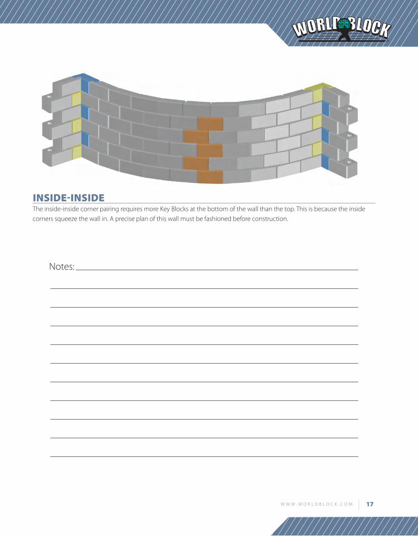
inSiDe-inSiDeThe inside-inside corner pairing requires more key Blocks at the bottom of the wall than the top. This is because the inside corners squeeze the wall in. A precise plan of this wall must be fashioned before construction.
notes:
17W W W . W O R L D B L O C k . C O M

geogriDinStallationusing no adhesives, geogrid is held in place solely by the weight of the block above it. Place the geogrid directly on the top of a block, making sure to cover the knobs. Remember to stop your geogrid 2 inches short of the front of the block because the wall will be step-ping back on the next course. Be sure to follow any specific manufacturer’s instructions when placing geogrid.
cornerSOutside corners are simply made by overlapping the geogrid around the corner. Do not cut any of the geogrid. Inside corners by convention would have no overlapping of the geogrid. To make the wall secure, leave a small amount of geogrid going through the cor-ner. This extra length should be 25% of the wall height. On the next course, do the same on the opposite side of the wall.
18 W O R L D B L O C k
InSTALLATIOn AnD EnGInEERInG MAnuAL

curveSOutside curves use standard, rectangular pieces of geogrid. Do not cut the geogrid, rather overlap each piece. Placing geogrid on inside curves will not cover the entire landscape behind it. To prevent problems, be sure to have geogrid covering these gaps on the next course.
19W W W . W O R L D B L O C k . C O M

BaSe BlocKSIn some situations you may want to create a taller wall without soil reinforcement. Using Base Blocks allows you to build 10 feet high with no geogrid.
Base Block walls are constructed very similarly to standard Landscape Block walls. However, there is no need for Base corner blocks. Our standard Landscape Corner Blocks do the job.
20 W O R L D B L O C k
InSTALLATIOn AnD EnGInEERInG MAnuAL

StePSUsing the Step Block forms allows you to create a stairwell for your project. The most important thing to notice before building a stairwell is that after every four courses of steps, your stairwell will be 4 inches wider. This is because the wall is stepping back 2 inches on each side. You’ll have to make your steps also 4 inches wider to account for this change in width.
notes:
21W W W . W O R L D B L O C k . C O M

fencingThe World Block Fence Post Blockout holds a 6 inch concrete forming tube. This creates a void where a fence post can be set and anchored with concrete. Now you can create any type of fence that fits your needs. This fence uses 4x4’s as posts, 2x4’s and a 2x8 as railings, and 2x2’s as slats.
22 W O R L D B L O C k
InSTALLATIOn AnD EnGInEERInG MAnuAL

terracingWhen terracing a wall, always begin installation where the running bond pattern is intact; trying to join terraced courses to create a running bond can be very difficult. During installation, be sure to use Recess Blocks only when completely separated from the main wall.
SeaWallSThere are many ways to build a wall into water, and it is a job that is very site-specific. Before build-ing any seawall, consult with a site engineer to ensure a safe design. Shown below, is a sample seawall. Included in its design is rip-rap, compacted aggregate, and filter fabric.
23W W W . W O R L D B L O C k . C O M

finiShing off your WallreceSS BlocKSRecess Blockouts create Recess Blocks which finish off your wall. Recess blocks are installed just like standard Landscape Blocks, and allow you to finish off your wall right to the block edge.
24 W O R L D B L O C k
InSTALLATIOn AnD EnGInEERInG MAnuAL

toP caPSAlthough top caps give your wall a clean, finished look, many challenges can arise during installation. Top Caps are 48 inches on one side, and 42 inches on the other. For a straight wall every Cap must be rotated 180˚. This breaks your running bond pattern as every other Cap has its short face to the front. You may need to cut the last Cap on your wall as it will likely hang off the edge.
using Top Caps to complete a curved wall requires more labor than Recess Blocks. It is very likely that Top Caps will not match the curvature of your wall. This means you will have to cut the ends of every Top Cap to match the wall’s curvature.
notes:
25W W W . W O R L D B L O C k . C O M

ProDuct SPecification guiDeSpecifier notes: This product guide specification is written according to the Construction Specifications Institute (CSI) 3.-Part Format, including MasterFormat, SectionFormat, and PageFormat, as described in The Project Resource Manual—CSI Manual of Practice, Fifth Edition.
This section must be carefully reviewed and edited by the Architect or Engineer to meet the requirements of the project and local building code. Coordinate this section with other specification sections and the Drawings. Delete all “Specifier notes” after editing this section.
Section numbers are from MasterFormat 2010 Update.
Section 32 32 17concrete lanDScaPe BlocK retaining WallS
Specifier notes: This section covers retaining walls made from concrete landscape blocks. The landscape block forms are manufactured by World Block, Inc. Consult World Block, Inc. for assistance in editing this section for the specific application.
Part 1 general1.1 Section incluDeS
a. Concrete landscape block retaining walls.
1.2 relateD reQuirementS
Specifier notes: Edit the following list of related sections as required. Limit the list to sections with specific information that the reader might expect to find in this section, but is specified elsewhere.
a. Section 03. 40 00 – Precast Concrete: Concrete for landscape blocks.
B. Section 3.3. 46 3.3. – Retaining Wall Drainage.
1.3 reference StanDarDS
Specifier notes: List standards referenced in this section, complete with designations and titles. Delete standards not included in the edited section. Including a standard in this list does not require compliance with that standard.
a. AASHTO M288 – Standard Specification for Geotextile Specification for Highway Applications.
26 W O R L D B L O C k
InSTALLATIOn AnD EnGInEERInG MAnuAL

B. ASTM D 422 – Standard Test Method for Particle-Size Analysis of Soils.
c. ASTM D 698 – Standard Test Methods for Laboratory Compaction Characteristics of Soil using Standard Effort (12 400 ft-lbf/ft3. (600 kn-m/m3.)).
D. ASTM D 1248 – Standard Specification for Polyethylene Plastics Extrusion Materials For Wire and Cable.
e. ASTM D 3.03.4 – Standard Specification for Type PSM Poly(Vinyl Chloride) (PVC) Sewer Pipe and Fittings.
f. ASTM D 43.55 – Standard Test Method for Deterioration of Geotextiles by Exposure to Light, Moisture and Heat in a Xenon Arc Type Apparatus.
g. ASTM D 4491 – Standard Test Methods for Water Permeability of Geotextiles by Permittivity.
h. ASTM D 453.3. – Standard Test Method for Trapezoid Tearing Strength of Geotextiles.
i. ASTM D 463.2 – Standard Test Method for Grab Breaking Load and Elongation of Geotextiles.
J. ASTM D 4751 – Standard Test Method for Determining Apparent Opening Size of a Geotextile.
K. ASTM D 5199 – Standard Test Method for Measuring the nominal Thickness of Geosynthetics.
l. ASTM D 5261 – Standard Test Method for Measuring Mass per unit Area of Geotextiles.
m. ASTM D 5262 – Standard Test Method for Evaluating the unconfined Tension Creep and Creep Rupture Behavior of Geosynthetics.
n. ASTM D 6241 – Standard Test Method for the Static Puncture Strength of Geotextiles and Geotextile-Related Products using a 50-mm Probe.
o. ASTM D 663.7 – Standard Test Method for Determining Tensile Properties of Geogrids by the Single or Multi-Rib Ten sile Method.
P. Geosynthetic Research Institute (GRI) GG4(b) – Standard Practice for Determination of the Long-Term Design Strength of Flexible Geogrids.
1.4 PreinStallation meetingS
Specifier notes: Edit preinstallation meetings as necessary. Delete if not required.
a. Convene preinstallation meeting 2 weeks before start of installation of concrete landscape block retaining walls.
B. Require attendance of parties directly affecting work of this section, including Contractor, Architect, Engineer, and installer.
c. Review the following:
1. Materials.
2. Excavation.
3. Installation.
4. Tolerances.
5. Field quality control.
6. Protection.
7. Coordination with other work.
27W W W . W O R L D B L O C k . C O M

1.5 SuBmittalS
Specifier notes: Edit submittal requirements as necessary. Delete submittals not required.
a. Comply with Section 01 3.3. 00 – Submittal Procedures.
B. Product Data: Submit manufacturer’s product data for the following:
1. Concrete landscape blocks.
2. Concrete landscape block forms.
3. Geogrid soil reinforcement.
4. Drainage collection pipe.
5. Geotextile filter fabric.
c. Reinforced Backfill: Submit reinforced backfill sample and laboratory test results to Engineer for approval before use of proposed reinforced backfill material.
D. Installer’s Project References: Submit installer’s list of successfully completed retaining wall projects, including project name and location, names of architect and engineer, and type and size of retaining walls installed.
1.6 Quality aSSurancea. Installer’s Qualifications:
1. Installer regularly engaged, for past 5 years, in installation of retaining walls of similar type and size to that specified.
2. Employ persons trained for installation of retaining walls.
1.7 Delivery, Storage, anD hanDling
a. Delivery and Acceptance Requirements: Deliver materials to site in manufacturer’s original, unopened containers and packaging, with labels clearly identifying product name and manufacturer.
B. Storage and Handling Requirements:
1. Store and handle materials in accordance with manufacturer’s instructions.
2. keep materials in manufacturer’s original, unopened containers and packaging until installation.
3. Protect materials during storage, handling, and installation to prevent damage.
28 W O R L D B L O C k
InSTALLATIOn AnD EnGInEERInG MAnuAL

Part 2 ProDuctS2.1 DeSign criteria
Specifier notes: Backfill soil and base soil properties vary greatly from site to site. An engineering analysis of soil proper-ties should be performed for each retaining wall installation. The Engineer should edit the following paragraph for the specific application.
a. Assumed Soil Properties:
1. Backfill Soil:
a. Soil Type: Poorly graded sand and gravel, well drained, Class SP.
b. Soil unit Weight: 110 pcf.
c. Internal Soil Friction Angle: 3.0 degrees.
d. Wall-Soil Friction Angle: 20.1 degrees.
2. Base Soil:
a. Soil Type: Gravel well drained and compacted.
b. Soil unit Weight: 125 pcf.
c. Internal Soil Friction Angle: 3.8 degrees.
B. Concrete Landscape Blocks:
1. Concrete unit Weight: 150 pcf.
2. Average Compressive Strength: 3.,000 psi.
3. Concrete-Soil Friction Factor: 0.67.
c. Factor of Safety Assumptions:
1. Retaining Wall Sliding: 1.5.
2. Retaining Wall Overturning: 2.0.
3. Soil Bearing Capacity: 3..0.
2.2 concrete lanDScaPe BlocKSa. Concrete Landscape Blocks:
1. Interlocking, concrete landscape blocks in shapes and sizes as indicated on the Drawings to create complete con-crete landscape block retaining walls.
2. Exposed stone face.
3. Step back 2 inches on every course.
B. Concrete Landscape Block Forms:
29W W W . W O R L D B L O C k . C O M

Specifier notes: Concrete landscape block forms manufactured by World Block, Inc. may contribute in achieving LEED certification by providing points in the following categories:
Materials and Resources:
Credit 3.: Materials Reuse
Credit 4: Recycled Content
Credit 5: Regional Materials
Consult World Block, Inc. for additional information.
1. Manufacturer: World Block, Inc., 3.964 East Calvary Road, Duluth, Minnesota 55803.. Toll Free 888-728-9481. Phone 218-728-9481. Fax 218-728-173.0. www.worldblock.com. [email protected].
2. Form Material: Steel.
3. nominal Dimensions of Basic Full Block: 24 inches by 24 inches by 48 inches.
4. Complete selection of concrete landscape block form categories, including:
a. Basic block forms.
b. Corner block forms.
c. Recess blockout forms.
d. Cap forms.
e. Step forms.
f. key block forms.
g. Base block forms.
h. Form Liners: Creates exposed stone face.
c. Concrete for Landscape Blocks:
1. Minimum Compressive Strength: 3.,000 psi at 28 days.
Specifier notes: When the retaining wall project is at a location with freeze/thaw cycles, the Engineer will determine the air content of the concrete.
2. Air Content: [ _______ percent] [Determined by Engineer].
3. Precast Concrete: Specified in Section 03. 40 00.
30 W O R L D B L O C k
InSTALLATIOn AnD EnGInEERInG MAnuAL

2.3 Soila. Base Leveling Pad Material: Compacted crushed stone base or nonreinforced concrete as indicated on the Drawings.
B. Drainage Fill:
1. Clean, 1-inch-minus crushed stone or crushed gravel.
2. Gradation, ASTM D 422:
a. 1-inch Sieve Size: 100 percent passing.
b. 3./4-inch Sieve Size: 75 to 100 percent passing.
c. no. 4 Sieve Size: 0 to 10 percent passing.
d. no. 50 Sieve Size: 0 to 5 percent passing.
3. use minimum of 1 cubic foot of drainage fill for each square foot of retaining wall face.
4. Place drainage fill between and behind concrete landscape blocks.
c. Reinforced Backfill:
1. Clean.
2. Gradation, ASTM D 422:
a. 2-inch Sieve Size: 75 to 100 percent passing.
b. 3./4-inch Sieve Size: 75 to 100 percent passing.
c. no. 40 Sieve Size: 0 to 60 percent passing.
d. no. 200 Sieve Size: 0 to 3.5 percent passing.
3. Maximum Aggregate Size: 3./4 inch, unless field tests performed to evaluate potential strength reductions to geogrid soil reinforcement design due to damage during construction.
4. Site Excavated Soils: Acceptable when specified requirements can be met.
5. Do not use unsuitable soils, including high-plastic clays or organic soils, for backfill or in reinforced soil mass.
2.4 geogriD Soil reinforcement
Specifier notes: The Engineer should specify the geogrid soil reinforcement for the specific application. Specify one of the following three types of geogrid.
a. Geogrid Soil Reinforcement: TenCate Mirafi “Miragrid 5XT”.
1. Description:
a. High-molecular-weight, high-tenacity polyester multifilament yarns woven in tension and finished with PVC coating.
b. Inert to biological degradation.
c. Resistant to naturally encountered chemicals, alkalis, and acids.
31W W W . W O R L D B L O C k . C O M

2. Mechanical Properties, Minimum Average Roll Value, Machine Direction:
a. Tensile Strength at ultimate, ASTM D 663.7: 4,700 lbs/ft (68.6 kn/m).
b. Tensile Strength at 5 Percent Strain, ASTM D 663.7: 1,740 lbs/ft (25.4 kn/m).
c. Creep Reduced Strength, ASTM D 5262: 2,975 lbs/ft (43..4 kn/m).
d. Long-Term Allowable Design Load, GRI GG4(b): 2,575 lbs/ft (3.7.6 kn/m).
3. Physical Properties:
a. Grid Aperture Size:
1) Machine Direction: 1.2 inch (3.0.5 mm).
2) Cross-Machine Direction: 1.0 inch (25.4 mm).
b. Mass/unit Area, ASTM D 5261: 9.0 oz/sq yd (3.05.1 g/m2).
c. Roll Dimensions, Width by Length: 12 feet by 150 feet (3..6 m by 45.7 m).
B. Geogrid Soil Reinforcement: TenCate Mirafi “Miragrid 8XT”.
1. Description:
a. High-molecular-weight, high-tenacity polyester multifilament yarns woven in tension and finished with PVC coating.
b. Inert to biological degradation.
c. Resistant to naturally encountered chemicals, alkalis, and acids.
2. Mechanical Properties, Minimum Average Roll Value, Machine Direction:
a. Tensile Strength at ultimate, ASTM D 663.7: 7,400 lbs/ft (108.0 kn/m).
b. Tensile Strength at 5 Percent Strain, ASTM D 663.7: 2,520 lbs/ft (3.6.8 kn/m).
c. Creep Reduced Strength, ASTM D 5262: 4,684 lbs/ft (68.3. kn/m).
d. Long-Term Allowable Design Load, GRI GG4(b): 4,055 lbs/ft (59.2 kn/m).
3. Physical Properties:
a. Grid Aperture Size:
1) Machine Direction: 1.3. inches (3.3..0 mm).
2) Cross-Machine Direction: 0.9 inch (21.8 mm).
b. Mass/unit Area, ASTM D 5261: 10.8 oz/sq yd (3.66 g/m2).
c. Roll Dimensions, Width by Length: 12 feet by 200 feet (3..6 m by 61 m).
c. Geogrid Soil Reinforcement: TenCate Mirafi “Miragrid 10XT”.
1. Description:
a. High-molecular-weight, high-tenacity polyester multifilament yarns woven in tension and finished with PVC coating.
b. Inert to biological degradation.
c. Resistant to naturally encountered chemicals, alkalis, and acids.
32 W O R L D B L O C k
InSTALLATIOn AnD EnGInEERInG MAnuAL

2. Mechanical Properties, Minimum Average Roll Value, Machine Direction:
a. Tensile Strength at ultimate, ASTM D 663.7: 9,500 lbs/ft (13.8.6 kn/m).
b. Tensile Strength at 5 Percent Strain, ASTM D 663.7: 3.,120 lbs/ft (45.5 kn/m).
c. Creep Reduced Strength, ASTM D 5262: 6,013. lbs/ft (87.7 kn/m).
d. Long-Term Allowable Design Load, GRI GG4(b): 5,206 lbs/ft (76.0 kn/m).
3. Physical Properties:
a. Grid Aperture Size:
1) Machine Direction: 1.3. inches (3.3..3. mm).
2) Cross-Machine Direction: 0.8 inch (20.8 mm).
b. Mass/unit Area, ASTM D 5261: 13..3. oz/sq yd (451 g/m2).
c. Roll Dimensions, Width by Length: 12 feet by 200 feet (3..6 m by 61 m).
2.5 geoteXtile filter faBric
Specifier notes: The Engineer should specify the geotextile filter fabric for the specific application.
a. Geotextile Filter Fabric: TenCate Mirafi “Mirafi 140n”.
1. Description:
a. needlepunched, nonwoven geotextile with polypropylene fibers formed into stable network such that fibers retain relative position.
b. Inert to biological degradation.
c. Resistant to naturally encountered chemicals, alkalis, and acids.
2. Compliance: AASHTO M288, Class 3. for elongation greater than 50 percent.
3. Mechanical Properties, Minimum Average Roll Value:
a. Grab Tensile Strength, ASTM D 463.2:
1) Machine Direction: 120 lbs (53.4 n).
2) Cross-Machine Direction: 120 lbs (53.4 n).
b. Grab Tensile Elongation, ASTM D 463.2:
1) Machine Direction: 50 percent.
2) Cross-Machine Direction: 50 percent.
c. Trapezoid Tear Strength, ASTM D 453.3.:
1) Machine Direction: 50 lbs (223. n).
2) Cross-Machine Direction: 50 lbs (223. n).
33W W W . W O R L D B L O C k . C O M

d. CBR Puncture Strength, ASTM D 6241: 3.00 lbs (1,3.3.5 n).
e. Apparent Opening Size (AOS), ASTM D 4751: 70 uS Sieve (0.212 mm).
f. Permittivity, ASTM D 4491: 1.7 sec-1.
g. Flow Rate, ASTM D 4491: 13.5 gal/min/sq ft (5,500 L/min/m2).
h. uV Resistance, 500 Hours, ASTM D 43.55: 70 percent strength retained.
4. Physical Properties:
a. Weight, ASTM D 5261: 4.8 oz/sq yd (163. g/m2).
b. Thickness, ASTM D 5199: 40 mils (1.0 mm).
c. Roll Dimensions, Width by Length:
1) 12.5 feet by 3.60 feet (3..8 m by 110 m).
2) 15 feet by 3.60 feet (4.5 m by 110 m).
2.6 Drainage collection PiPea. Drainage Collection Pipe:
1. PVC, ASTM D 3.03.4 or corrugated HDPE, ASTM D 1248 pipe.
2. Perforated or slotted.
Part 3 eXecution3.1 eXamination
a. Examine areas to receive concrete landscape block retaining walls.
B. notify Architect of conditions that would adversely affect excavation or installation.
c. Do not begin excavation or installation until unacceptable conditions are corrected.
3.2 generala. Construct concrete landscape block retaining walls to lines, grades, dimensions, design, and pattern indicated on the Drawings.
3.3 eXcavationa. Excavate to lines and grades indicated on the Drawings.
B. Owner’s representative will inspect excavation and approve before placement of leveling material or backfill.
c. Proofroll foundation area as directed to determine if remedial work is required.
D. Following excavation for leveling pad and reinforced soil zone, soil will be examined by Engineer to assure actual foun-dation soil strength meets or exceeds assumed design bearing strength.
e. Remove and replace soils not meeting required strength with soil meeting design criteria, as directed by Engineer.
34 W O R L D B L O C k
InSTALLATIOn AnD EnGInEERInG MAnuAL

3.4 BaSe leveling PaDa. Place Leveling Pad Material to:
1. Lines and grades indicated on the Drawings.
2. Minimum thickness of 6 inches.
3. Extend laterally a minimum of 6 inches in front and behind concrete landscape blocks.
B. Compact soil leveling pad material to a minimum of 95 percent of maximum Standard Proctor density in accordance with ASTM D 698.
c. Prepare leveling pad to ensure full contact with base surface of concrete landscape blocks.
3.5 concrete lanDScaPe BlocK inStallationa. Install concrete landscape blocks in accordance with concrete landscape block manufacturer’s instructions.
B. Place first course of concrete landscape blocks on leveling pad at proper line and grade.
c. Check alignment and level in all directions.
D. Ensure concrete landscape blocks are in full contact with base and properly seated.
e. Place front of concrete landscape blocks side-by-side.
f. Do not leave gaps between adjacent blocks.
g. Layout corners and curves in accordance with concrete landscape block manufacturer’s instructions.
h. Place and compact drainage fill within and behind concrete landscape blocks.
i. Place and compact backfill soil behind drainage fill.
J. Follow retaining wall erection and drainage fill closely with structure backfill.
K. Do not exceed 1 course of stacked vertical height of concrete landscape blocks, before drainage fill and backfill place-ment and compaction.
3.6 geoteXtile filter faBrica. Install geotextile filter fabric in accordance with geotextile filter fabric manufacturer’s instructions.
B. Wrap drainage collection pipe and drainage aggregate with geotextile filter fabric.
3.7 geogriD Soil reinforcement inStallationa. Install geogrid soil reinforcement in accordance with geogrid soil reinforcement manufacturer’s instructions.
B. Install geogrid soil reinforcement at location, elevation, length, and orientation as indicated on the Drawings or as directed by Engineer.
c. Orient geogrid soil reinforcement with highest strength axis perpendicular to retaining wall alignment.
D. Lay geogrid soil reinforcement horizontally on compacted backfill and attach to concrete landscape blocks.
35W W W . W O R L D B L O C k . C O M

e. Place next course of concrete landscape blocks over geogrid soil reinforcement.
f. Pull geogrid soil reinforcement taut, free of wrinkles and anchor before backfill placement on geogrid soil reinforcement.
g. Ensure geogrid soil reinforcement is continuous throughout embedment length and is placed side-by-side to provide 100 percent coverage at each level.
h. Do not splice connections between shorter pieces of geogrid soil reinforcement.
i. Do not allow gaps between adjacent pieces of geogrid soil reinforcement.
3.8 reinforceD BacKfill Placementa. Place, spread, and compact reinforced backfill to minimize slack in geogrid soil reinforcement and installation damage.
B. Place and compact reinforced backfill in maximum 6-inch lifts where hand compaction is used or maximum 8 to 10- inch lifts where heavy compaction equipment is used.
c. Decrease lift thickness to achieve required density, if necessary.
D. Compact reinforced backfill to 95 percent of maximum density in accordance with ASTM D 698.
e. Ensure moisture content of reinforced backfill before and during compaction is uniformly distributed throughout each layer and is dry of optimum, plus 0 percent, minus 3. percent.
f. Construction Equipment:
1. Allow only lightweight hand-operated equipment within 3. feet from soil side of concrete landscape blocks.
2. Do not operate tracked construction equipment directly on geogrid soil reinforcement.
3. Provide minimum backfill thickness of 6 inches before operation of tracked vehicles over geogrid soil reinforce-ment.
4. keep tracked vehicle turning to a minimum to prevent tracks from displacing backfill and damaging geogrid soil reinforcement.
5. Do not allow rubber-tired equipment to pass over geogrid soil reinforcement at speeds greater than 10 mph.
6. Avoid sudden braking and sharp turning with rubber-tired equipment.
g. Slope last lift of reinforced backfill away from concrete landscape blocks to direct runoff away from retaining wall face, at end of each day’s operation.
h. Do not allow surface runoff from adjacent areas to enter retaining wall construction site.
3.9 toleranceSa. Retaining Wall Vertical Alignment: Plus or minus 1.5 inches over any 10-foot distance.
1. Retaining Wall Batter: Plus or minus 2 degrees of design batter.
B. Retaining Wall Horizontal Alignment: Plus or minus 1.5 inches over any 10-foot distance.
1. Corners, Bends, and Curves: Plus or minus 1 foot to theoretical location.
36 W O R L D B L O C k
InSTALLATIOn AnD EnGInEERInG MAnuAL

c. Maximum Horizontal Gap Between Concrete Landscape Blocks: 1/2 inch.
3.10 fielD Quality control
Specifier notes: Specify field quality control to be performed by the Owner and the Contractor. Edit the following as required.
a. Owner’s Field Quality Control: Owner will engage inspection and testing services, including independent laboratories, to provide quality assurance and testing services during construction.
B. Contractor’s Field Quality Control:
1. Perform necessary field quality control testing during construction using qualified and experienced personnel.
2. Include the following as a minimum:
a. Foundation soil inspection.
b. Soil and backfill testing.
c. Verification of design parameters.
d. Observation of construction for general compliance with the Drawings and specifications.
3.11 Protectiona. Protect installed concrete landscape block retaining walls to ensure that, except for normal weathering, retaining walls will be without damage or deterioration at time of Substantial Completion.
notes:
37W W W . W O R L D B L O C k . C O M

notes:
38 W O R L D B L O C k
InSTALLATIOn AnD EnGInEERInG MAnuAL

notes:
39W W W . W O R L D B L O C k . C O M

3964 East Calvary roadduluth, MN 55803
www.worldblock.comthE World’sBloCK ForMCoMPaNy
#1