Installation and demonstration of - Seljemoseljemo.com/espen/master/master_thesis/Project report...
84
Installation and demonstration of ABB Industrial IT 800xA system at Narvik University College 20.10.2006 Project report By Kristian Knudsen and Espen Seljemo Master of Science students at Narvik university college, department of Industrial Engineering
Transcript of Installation and demonstration of - Seljemoseljemo.com/espen/master/master_thesis/Project report...

Installation and demonstration of
ABB IndustrialIT 800xA system
at Narvik University College
20.10.2006
Project report
By
Kristian Knudsen and Espen Seljemo
Master of Science students at
Narvik university college, department of Industrial Engineering

Installation and demonstration of
ABB IndustrialIT 800xA system
Master of Science in Technology
NARVIK UNIVERSITY COLLEGE
Telephone: 76 96 60 00
Title Installation and demonstration of ABB IndustrialIT 800xA SYSTEM at Narvik University College
Date 20.10.2006
Gradation: Open
Authors Kristian Knudsen Espen Seljemo
Amount of pages
33 Appendices
6
Department for
IBDK Major subject
Industrial Engineering
Supervisor Bjørn Solvang
Enterprise PL/HIN
Contact person
Bjørn Solvang
Abstract
This project is an introduction to the IndustrialIT 800xA system made by the firm Asea Brown Boveri (ABB). It is a very large, modern automation- and control system and it is installed at many oil and gas facilities world wide. The 800xA system is not a plug and play equipment. There are many options that must be taken before system installation and during the installation to create exactly the environment you want. The different communication forms and the width of possibilities with the I/O modules make the 800xA hardware very scaleable against existing systems that already exist on the market. Keywords
Asea Brown Boveri, ABB, IndustrialIT, AC 800M controller, Automation, Network topology, software, hardware, I/O modules, analogue input and output, digital input and output, 800xA system, interface, cable connection, communication

1
Preface The problem with most automation control systems is that they are seldom more than a control system. This is where IndustrialIT system shows its true colors as a complete system including control, analysis and maintenance in only one package. This report is written by two master degree students at Narvik University College (NUC), and is a part of the course Prosjektfag. We both have a Bachelor degree in Automation from Høgskolen i Tromsø. The object of this project is to set up a simple system using IndustrialIT 800xA system from ABB. This is also an introduction project to our Master thesis. The duration of this project is 15 days. The main sources of this report are the research we have done and the documentation by ABB. The documentation made by ABB is very thorough and extensive, this makes it both good and hard to use. The total size of the documentation is approximately 16.000 pages which is renders it difficult to get trough it all. The project main goal is to make us comfortable with IndustrialIT. This could have been done by sending us on the courses held by ABB. But as NUC has a “no course” policy, we are learning this by ourselves doing the trail and fail method. It actually makes us understand the system better. Our journey trough the installation, configuration, and finally, testing our system will give us the insight needed to show why IndustrialIT is such a success. We would like to thank our supervisor Bjørn Solvang for the help he has given us during this project and our laboratory chief Tony Inge Ludvigsen. We would also like to thank ABB by Ståle Stenberg and Arne- Ivar Iversen for their outstanding support on IndustrialIT system. Narvik 20.10.2006 _______________________ _______________________ Kristian Knudsen Espen Seljemo

2
Abstract This project is an introduction to the IndustrialIT 800xA system made by the firm Asea Brown Boveri (ABB). It is a very large, modern automation- and control system and it is installed at many oil and gas facilities world wide, onshore and offshore and at other industrial facilities. For example Statoil`s LNG facility Snehvit located at Hammerfest. IndustrialIT 800xA is a huge and flexible system with many communication opportunities to already exciting technology like Fieldbus, profibus and Hart. This makes it easy to communicate with other systems and at the same time give the users the benefits that IndustrialIT system gives. It is equipped with powerful hardware and software which have many opportunities to design and implement the system exactly after the given requirements. We created a small system which consists of: One computer, one AC 800M controller and I/O modules. Made a short program where we simulated the movement on sliding doors in a shop when customers arrive. This program gave us an opportunity to test data communication between computer and 800xA hardware equipment. The 800xA system is not a plug and play equipment. There are many options that must be taken before system installation and during the installation to create exactly the environment you want. This makes the system very flexible and it can be installed or implemented in almost any industrial environment. In this project we had to read the following installation manuals for the 800xA system and installed hardware and software systems separately before trying to communicate with both parts. When installing this system we got a few but solid problems. We discovered that the 800xA system is not just a Plug and Play package. There are many opportunities and choices that must be made in planning the system and during the installation. We used the trail and fail method to solve different problems that was not explained in the manuals. Some problems that occurred in the installation process where very strange and we could not find a solution to it so we needed to contact ABB for support. The different communication forms and the width of possibilities with the I/O modules make the 800xA hardware very scaleable against existing systems that already exist on the market. Future work with 800xA system is to install a bigger solution which includes 3 nodes in a network. One server node connected to a main controller with analogue or digital equipment attached. On the other two nodes in this network we will create one operator workplace and one engineering workplace.

3
Vocabulary
AC Alternating current, where current direction vary cyclically.
AC 800M Controller A controller which handles the signals from I/O modules.
AluRack A homemade rack for using in school experiments. These are equipped with DIN rail for connecting electrical components.
Aspect Server “A server that runs the central functions of the Aspect Object
architecture, such as Aspect Directory, Structure and Name Server, Cross Referencing, File Set Distribution, and so on. The Aspect Server is normally used as the Windows domain controller for the control and client/server networks.” [9]
Aspect System A software system, which implements one or several aspect
types by providing one or several Aspect System Objects. [9]
Connectivity Server A server that provides access to controllers and other sources for real-time data, historical data, and alarm and event data. A node containing this is in our case connected to the AC 800M controller. [9]
Control system A system used to automate a facility or process. Example; controlling the air and heat in a building.
DC Direct current, constant flow of electrons in one direction.
DIN rail Standardized 35mm wide metal rail where electronic equipment easily can be mounted on.
Foundation Fieldbus Fieldbuses are a type of industrial communication standard. You can use several forms of transmitting data such as copper cable, fiber optics or wireless. [8]
Hardware Physically equipment.
IndustrialIT ABB’s vision for enterprise automation. [10]
I/O Module Blocks that are connected to the AC 800M controller. These can be either analog or digital, and handle input or output signals.
IP Internet protocol standard for communication between nodes in a network
LED Light Emitting Diode.
MAC Media access control is a unique ID address on the network card. This address determines who is allowed to connect physically to the media or node.
Node A computer communicating on a network e.g. the Internet, Plant, Control or I/O network. Each node typically has a unique node address with a format depending on the network it is connected to.
4
Profibus A type of Fieldbus communication standard. This is one of the most universal Fieldbuses.[8]
RJ 45 Connection plug on Ethernet communication cable
Software Computer programs for different use.
Topology The method or specific way computers and other network devices are put together in network.

5
Figure list Figure 1 Historical review .................................................................................................. 9 Figure 2 View over different aspects in IndustrialIT 800xA system ................................. 10 Figure 3 AC 800M controller ........................................................................................... 12 Figure 4 MTU Bracket...................................................................................................... 13 Figure 5 I/O Module ......................................................................................................... 13 Figure 6 AC 800M with two I/O modules ........................................................................ 14 Figure 7 Power Supply SD 821 ........................................................................................ 15 Figure 8 Own designed AluRack...................................................................................... 16 Figure 9 Connection example [5] ..................................................................................... 17 Figure 10 Internet protocol TCP/IP settings on PC .......................................................... 18 Figure 11 Topology tree of computer, controller and I/O [3]........................................... 19 Figure 12 Interference between interfaces in the 800xA system [7] page 43................... 22 Figure 13 Process portal and OPC server placing ............................................................ 23 Figure 14 Hardware tree in program Control Builder M Professional ............................. 23 Figure 15 Plant explorer workplace layout window......................................................... 24 Figure 16 Program editor window .................................................................................... 25 Figure 17 Real object, Process window and Aspect objects [4] ....................................... 27 Figure 18 System connections on our 800xA system....................................................... 29 Figure 19 Future topology with tree nodes ....................................................................... 30 Figure 20 Command prompt window............................................................................... 36 Figure 21 Setup wizard for OPC server account .............................................................. 37 Figure 22 Configuration Wizard start ............................................................................... 82 Figure 23 Configuration Wizard....................................................................................... 82
Table list Table 1 Contents of 800xA system.................................................................................. 11 Table 2 Hardware requirement ......................................................................................... 11 Table 3 I/O modules information...................................................................................... 13 Table 4 Connection table 220V ........................................................................................ 15 Table 5 Connection table 24V .......................................................................................... 15 Table 6 Example of IP adresses ........................................................................................ 18 Table 7 Scheme over diagnostic LED’s on AC 800M [1]................................................ 36

6
Contents 1. Introduction..................................................................................................................... 7 2. Asea Brown Boveri (ABB)............................................................................................. 8 3. Historical review of automation systems........................................................................ 9 4. IndustrialIT 800xA system............................................................................................. 10 5. Hardware....................................................................................................................... 11
5.1 Computer requirements..................................................................................... 11 5.2 AC 800M Controller ............................................................................................... 12 5.3 I/O modules....................................................................................................... 13 5.4 Power supply..................................................................................................... 15 5.5 AluRack ............................................................................................................ 16
6 Communication......................................................................................................... 17 6.1 Cabling and Connections .................................................................................. 17
6.1.1 Switch or a hub ................................................................................................ 18 6.1.2 Directly to AC 800M controller....................................................................... 18
6.2 Network addresses ............................................................................................ 18 6.3 Firmware communication ....................................................................................... 19 6.4 Network topology ............................................................................................. 19
7 Software .................................................................................................................... 20 7.1 Software license ................................................................................................ 20 7.2 Software requirements ...................................................................................... 21 7.3 How to use the IndustrialITSoftware ................................................................. 21 7.4 Project explorer...................................................................................................... 23 7.5 Creating a new project ............................................................................................ 23 7.6 Plant Explorer ......................................................................................................... 24
7.6.1 Make a program ............................................................................................... 25 7.7 Offline programming .............................................................................................. 26 7.8 Draw network topology of a system ....................................................................... 26 7.9 Aspect object technology........................................................................................ 27
8. Result of the project ...................................................................................................... 28 8.1 Our 800 xA system ........................................................................................... 29 8.2 Future system configuration ............................................................................. 30
9 Capabilities of the 800xA system ............................................................................. 31 10 Discussion ............................................................................................................. 32 11 Conclusion ............................................................................................................ 33 12 References.................................................................................................................... 34 Appendix I. Documents attached on project CD .............................................................. 35 Appendix II. Troubleshooting........................................................................................... 36 Appendix III. Task description for IndustrialIT 800xA system project............................. 38 Appendix IV. Activity schedule for this project ............................................................... 40 Appendix V. System installation ...................................................................................... 41 Appendix VI. Post installation.......................................................................................... 82

7
1. Introduction This project ultimately started when NUC got sponsored the IndustrialIT 800xA system from ABB. A package which contained of 4 sets with one AC 800M controller and several analogue and digital modules. Since this is a completely new system there was no one to set it up in the lab at NUC. We took upon us this task in May 2006, but we really got the project going when the course Prosjektfag started. As mentioned before there where no one but us who could set up the IndustrialIT system at NUC. This was the beginning of our task. Usually persons with background knowledge on the system would set it up. There are different courses varying from beginner to expert and they are lasting up to three days. It was not an alternative for us to go on these courses since we are under the impression that we would learn more by figuring it out on our own, and some help from the instruction manuals. The report is built up in the following manner: First explaining what IndustrialIT is, then we will present a short historical review on automation systems before we explain what the system consist of. The Industrial IT 800xA can be divided in two parts, one hardware part and one software part, this will be reflected in our report. The two main chapters will describe these parts and a final part will explain the communication between software and hardware. Our activity schedule and description on this project task can be seen in Appendix III and IV. This project is the evaluation form in the course Prosjektfag and it will also make the introduction to our Master thesis and other future school projects. We restrict our work to just install a small single node system with enough options to make a presentation and introduction of this powerful software and hardware package.

8
2. Asea Brown Boveri (ABB) The company which has produced the IndustrialIT is called Asea Brown Bovery (ABB). Here is a little background on the firm. In the late 1880`s the start of today’s firm ABB was created by Asea in Sweden and BBC in Switzerland.
Asea was established back in year 1883. They where manufacturing electrical lightning and generators in Sweden. Eight years later in Switzerland the firm Brown, Boveri and Cie (BBC) was established in year 1891. They where working with high voltage AC power equipment.
In year 1988 the two companies Asea and BBC merged into one company Asea Brown Bovery. Today ABB is a world leading firm within electrical power, automation technology and robotics. Within the firm there are different divisions who are focusing on their core strengths: Power products and systems, automation products, process automation and robotics. ABB is located all over the world. This gives them a short distance to their markets within power and automation. Their vision is to provide leading power and automation technology to customers around the whole world. A broad application know- how gives their customers fast and reliable support which is some of their qualities. For more information, please see www.abb.com

9
3. Historical review of automation systems If we look back in time and see with a historical perspective on which control, and automation systems we got. An illustration on when the different automation system was created is shown in Figure 1.
Figure 1 Historical review
Early forms of automation were driven by clock type mechanisms or similar devices using some form of artificial power source, a wound-up spring, channeled flowing water, or steam. In 1801, the patent was issued for the automated loom using punched cards. In 1835 the relay was invented and was used up to late 1960 in automation, and it is still used today in small and less complicated systems. Programmable Logic Controller (PLC) was invented 1968 and replaced the relay automation. The PLC is still one of the most used controllers in automation, but it has its lacks. In 2004 the IndustrialIT 800xA system was released by ABB, and it soon became a success in the world of industry.

10
4. IndustrialIT 800xA system IndustrialIT 800xA system is a control system developed by ABB and was launched in January year 2004. It is based on the principle of a PLC with the thought of a “brain” controlling several I/O modules, but it is far more advanced. You might say that it is the next generation of automation and control system. The 800xA system includes many automation processes in one environment. It collects many process controls and windows that can be presented on one system platform. With this system there is no need for many different software packages and different hardware solutions to make your process system speak together. IndustrialIT 800xA has everything implemented and it can be connected to almost any old hardware communication systems and new devices. For example (PLC, profibus, Fieldbus or HART) Every control, maintenance and other important processes are collected and integrated into one environment. Such as: Supervision of devices (motors, valves, etc), maintenance data and documents, device and system drawings, control values, process values, and other important information can be presented into one interface. System 800xA gathers information from all these different sources in the process and presents this data in an interface which is being used by: Technicians, production managers, operators or engineers. Different aspects of what IndustrialIT 800xA system contains of is illustrated in Figure 2
Figure 2 View over different aspects in Industrial
IT 800xA system

11
.
5. Hardware The IndustrialIT 800xA hardware used in this project is delivered by ABB. Other equipment and materials is delivered by NUC. This chapter will describe the different parts used in this project. In Table 1 there is a list over the hardware that NUC got sponsored from ABB. This hardware can be assembled into a big system or it can be divided into max four small systems. All hardware can be mounted onto standardized DIN rails. We decided to create only one small system, which is described in part 8.1 in this report. A hardware system consist of a main unit, the AC 800M controller and some analogue or digital I/O modules attached. Numbers of modules that can be used depends on your process and what it requires.
Table 1 Contents of 800xA system
800xA system modules
Module type Total units
AC 800M 4
AO810 4
AI810 4
DI810 4
DO810 4
MTU bracket 16
Power Supply 4
5.1 Computer requirements
Since the 800xA system has a powerful software package it demands a lot of resources from the hardware on the computer. Many sub programs from 800xA are processed while Windows is running. A fast computer is recommended. See Table 2 for more details about hardware requirements on different computer installations.
Table 2 Hardware requirement
Server node Workstation node
(Operator)
Single node
(Operator/Engineer)
CPU At least 2,0 GHz CPU
At least 2,0 GHz CPU
At least 2,0 GHz CPU
RAM 2GB RAM Minimum 1GB RAM
2GB RAM
Hard drive 7200 rpm or higher 7200 rpm or higher 7200 rpm or higher
Operating system Windows XP Pro English version
Windows XP Pro English version
Windows XP Pro English version

12
5.2 AC 800M Controller
AC 800M controller, shown in Figure 3, is the main unit in hardware system. This unit contains of a 24 MHz CPU and 8MB of internal memory. Up to 12 I/O modules can directly be connected to the controller via the electrical Modulebus and 84 I/O modules can be connected to I/O clusters via the optical Modulebus. The controller is also equipped with a backup battery and a compact flash memory slot which can be used to store programs or be a safety device to prevent data loss when power failures interfere.
Figure 3 AC 800M controller
Main task of the controller is to send and receive I/O module signals from/to a computer. Controller is equipped with two Ethernet ports for communication with other subsystems, in a network such as operators or engineers. It also has two RS-232 ports for 3rd party devices or for communication with program/debugging tools. There is also connection for the usage of fiber optics communication which is recommended in areas with high electromagnetic interference. The mounting bracket on the AC 800M controller is made of metal. Because of this the entire system will be grounded when you mount it to a DIN rail, if the DIN rail is grounded. This means that the I/O modules that are attached to AC 800M controller are also are grounded from this connection. Grounding is done to prevent interference from surrounding systems that can interfere with the internal logic. AC 800M controller is very flexible to communicate with other existing systems like: RS-232, Profibus, Foundation Fieldbus, HART, TCP/IP Network or Fiber optics.

13
5.3 I/O modules
To open up for communication with equipments in the field it is necessary with a link between the AC 800M controller and the equipments. This is where the I/O modules enter. Equipment out in the field is connected directly to the modules. There are 4 main groups of modules: Analogue in (AI), analog out (AO), digital in (DI) and digital out (DO). What type of modules that are being used depends on if there is an analogue or digital signal that is being sent out from the equipment. See Table 3 I/O modules informationfor details about analogue and digital modules.
Table 3 I/O modules information
Module Type Channels Signal Type
Analog In 8 0..20mA, 0..10V
Analog Out 8 0..20mA
Digital In 2x8 24V
Digital Out 2x8 24V
I/O modules are attached to a MTU bracket. This must be done manually by pressing the I/O module into the MTU bracket. There are some switches that must cohere before this can be done. MTU bracket is shown in Figure 4 and the I/O module is shown in Figure 5. Switches on the I/O module is not shown in the picture since it is on the backside of the module.
Figure 4 MTU Bracket
Figure 5 I/O Module

14
Different I/O modules that can be attached to the AC 800M controller by sliding them into the controller. This is shown in Figure 6 where you have a control unit and two I/O units. These are clipped on a DIN rail which is mounted on the AluRack. For more information about installing the modules please see [2] page 76.
Figure 6 AC 800M with two I/O modules
I/O modules can be switched and replace when system is running and powered on. Only the devices that are connected to this module will not work properly when failure interfere In oil and gas business a total shut down of entire system can cost a lot of money. Application data can be stored at compact flash memory at every AC 800M controller so it will be no data loss after a power failure or during module replacements. In case there should be an error on the modules a LED on the front of the module will light up.

15
5.4 Power supply
A power supply is used to serve the 800xA hardware system with power. The power supply converts 220V AC (input current) into 24V DC (output current), the power supply is shown in Figure 7.
Figure 7 Power Supply SD 821
Power supply has a LED in upper left corner witch can tell if the power signal is OK or not. The input current (220V AC) is placed underneath the power supply and the output (24V DC) is placed on top. The connections are described in Table 4 and Table 5. 24V DC is coming out pins L+ and L-. When handling direct current it is very important to connect positive (+) to positive and negative(-) to negative. These must not be crossed.
Table 4 Connection table 220V
N L1
L L2
PE Earth
Table 5 Connection table 24V
L+ +24V
L- 0V
Power cables from L+ and L- on the controller must also be connected on L+ and L- on the MTU bracket.
16
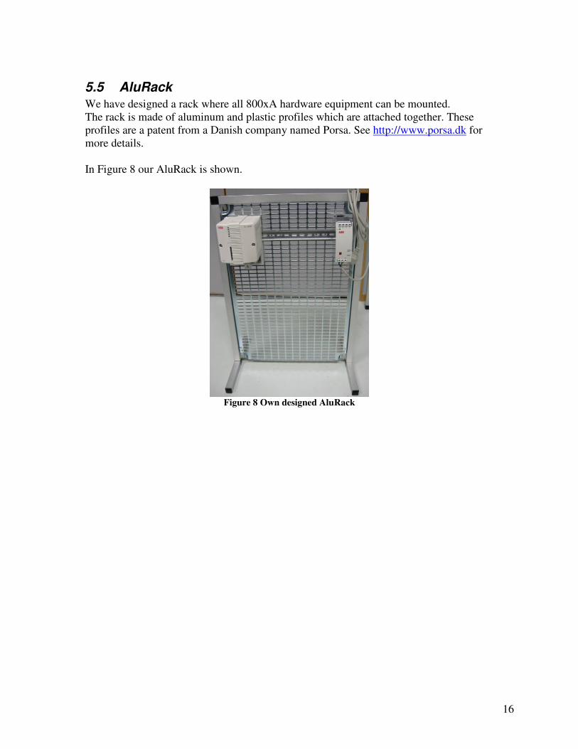
5.5 AluRack
We have designed a rack where all 800xA hardware equipment can be mounted. The rack is made of aluminum and plastic profiles which are attached together. These profiles are a patent from a Danish company named Porsa. See http://www.porsa.dk for more details. In Figure 8 our AluRack is shown.
Figure 8 Own designed AluRack

17
6 Communication This chapter will describe different forms of communication between computer and controller in the 800xA system.
6.1 Cabling and Connections
There are mainly two ways to do the communication between a computer and controller, it is optical or using twisted pair Ethernet cable. Signal and communication cables must not be routed nearby power cables with high voltage. This can interfere with the signals. Choose shielded twisted pair cable to minimize the interference, or fiber optic cable to remove all interference.
AC 800M controller has fiber optic as a connection option. With use of the fiber optic port a 800xA system can be placed at any extreme electromagnetic conditions and still be unaffected by it. In Figure 9 we see an example on how the connection should be done and what type of cable that should be used.
Figure 9 Connection example [5]

18
There are to ways of connections that can be used between the computer and AC 800M controller, it is directly or using a switch or hub in a network.
6.1.1 Switch or a hub Plug an shielded twisted pair Ethernet cable with RJ 45 connection plug into CN 1 port on AC 800M controller and the other end into a switch or a hub.
6.1.2 Directly to AC 800M controller
If you are connecting directly from a computer to a controller it is important to use a crossed shielded twisted pair Ethernet cable. The cable must be plugged into CN1 port on the controller.
6.2 Network addresses
It is important to set up right addresses on the computer and AC 800M controller. The IP address on the computer must in the same address area as the controller. See Table 6 for an example. The IP address of the computer can be shown by selecting properties on the networkcard in Windows XP. This is shown in Figure 10Figure 10.
Table 6 Example of IP adresses
PC IP: 172.16.0.100
AC 800M IP: 172.16.0.201
Figure 10 Internet protocol TCP/IP settings on PC
19
6.3 Firmware communication
Program Control builder M professional and AC 800M controller must have the same version of firmware. If they do not have same version the system will not work properly. See [6] for more details on how to check the firmware versions.
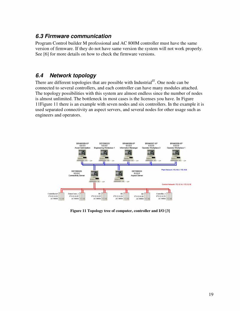
6.4 Network topology
There are different topologies that are possible with IndustrialIT. One node can be connected to several controllers, and each controller can have many modules attached. The topology possibilities with this system are almost endless since the number of nodes is almost unlimited. The bottleneck in most cases is the licenses you have. In Figure 11Figure 11 there is an example with seven nodes and six controllers. In the example it is used separated connectivity an aspect servers, and several nodes for other usage such as engineers and operators.
Figure 11 Topology tree of computer, controller and I/O [3]

20
7 Software The software we use in this project is a package named IndustrialIT developed by ABB. It is a multi-usage package for automating and analyzing processes and activities in a facility. To make the IndustrialIT software pack work there are some necessary steps that needs to be taken.
1. Install system shell, described in Appendix V 2. Plan the system using System Planning tool, described in Appendix V 3. Do a post installation on the system, described in [6] 4. Configure users/user groups and connection, described in [7] 5. Set up your automation system, described in [7]
The software is integrated in Windows platform enabling the IndustrialIT to take full control over the computer. An operator logs on to Windows and gain the user rights an operator should have. When an engineer logs on the user rights will change to what an engineer needs.
7.1 Software license
A license file is needed on every computer that is connected to an AC 800M controller. This file is made ABB and contains information from the computer. NUC got license on: One Core system, one operator workplace and one engineer workplace. Every network card in a computer has a unique identification address called Media Access Control, or better know as MAC. This address is found by using command prompt window and typing in the command ipconfig /all Recognize the name on the network card that you are connecting to the AC 800M controller. Under this network card the correct MAC address is listed. This MAC address is implemented into the license file.

21
7.2 Software requirements
The IndustrialIT 800xA system has some software requirements. These are important when installing the IndustrialIT system. Required assets for installation:
- Windows XP Professional English version - CD/DVD Package from ABB - Administrator rights on the computer - Microsoft Word and Excel 2003 or newer - Diskette with a system created in System Planner - Turn off Windows Firewall and other firewalls that are included in some virus
programs. - Download all hot fixes for your Windows XP from Windows update on the
Internet. This must be done to have a stable and safe system before you do anymore installation. Note: This can only be done if you are using computers with pre-installed Windows. If you are using a blank computer you will be prompted to install hot-fixes during the installation.
7.3 How to use the IndustrialITSoftware
This part will explain different programs that are included in the IndustrialIT and how to create a new automation system. When all pre- and post installation is done to the system it is ready to make an automation system on the computer. To make such a system there are two important programs that are being used, it is Project explorer and Plant Explorer. See Figure 12Figure 12 for interference between these to software interfaces and the AC 800M controller. More details on how to do the post installation is described in appendix VI From now on there are different windows and possibilities in the computer system because of the different user rights between an engineer and operator.

22
Figure 12 Interference between interfaces in the 800xA system [7] page 43

23
7.4 Project explorer
The program Control Builder M Professional is also called Project Explorer after all installation and configuration is done to the system. In project explorer it is possible to make and set up a new project for your system.
7.5 Creating a new project
A new project can be started from program Control Builder M Professional. Choose New project and AC 800M controller in this program. 800xA hardware system with controller and I/O modules must be connected to the computer. The process portal and OPC server must be running. This can be seen by a green icon (process portal) and a grey icon (OPC server) which are placed in the right corner on the desktop. See Figure 13Figure 13 Process portal and OPC server for more details.
Figure 13 Process portal and OPC server placing
The same 800xa hardware system that is mounted together must be remade in a hardware tree in the program Control Builder M Professional. All I/O modules in the system must are placed under ModuleBus in the hardware tree. After creating this tree the next step is to download this setup to the AC 800M controller. This is done in the same program where the hardware tree is made. See Figure 14 Figure 14 Hardware tree in program Control Builder M Professionalfor more details on the placing of the hardware tree.
Figure 14 Hardware tree in program Control Builder M Professional

24
7.6 Plant Explorer
The Plant Explorer is the heart of all IndustrialIT programs. This is where all configurations and calibrations to the 800xA system are done. In Plant Explorer it is possible to make automation programs. See Figure 15 for Plant explorer workplace layout. Here the same hardware tree that was made in Control Builder M Professional is reproduced. There is also created a new Control project called HiN. In Plant explorer alarms and events for the whole system is calibrated and configured. Every changes made in Plant explorer are automatically updated in the program Control Builder M Professional.
Figure 15 Plant explorer workplace layout window

25
7.6.1 Make a program
A control program is made by starting Program editor in Program1, 2 or 3 under Programs in the hardware tree. In the program editor it is possible to use different kinds of programming languages like: Structured text, structured function chart etc. See Figure 16 for layout on Program editor. In this example there is made a program of simulation sliding doors in a shop.
Figure 16 Program editor window
26
7.7 Offline programming
Test a program in offline mode is important to do before sending it to a controller. A offline test is a safe way to check for errors and malfunctions in a program Instructions on how to go in offline mode can seen in [7] at page 82.
7.8 Draw network topology of a system
In Plant explorer it is possible to draw the network topology in program Topology
designer. There are different templates to draw network connections or internal hardware connections between controller and I/O modules. The finished network topology drawing can be imported to the process window so that an operator or engineer can see how things are connected together.

27
7.9 Aspect object technology
In a process window ABB uses aspect object technology to present and sort all information about a process in an interface. The Aspect Server collects all information about real time process and devices are present in one graphical interface. In this interface there is collected many types of information on a device like: Trend graphics, alarms, engine data, controls, maintenance objects and other graphic elements. See Figure 17 for more details on aspect technology.
Figure 17 Real object, Process window and Aspect objects [4]
All field devices that are connected to AC 800M and I/O modules can be configured, monitored and controlled by an operator. Aspect object technology is both time and money savings if there are any failure at a device or processes. The operator has all information collected on this device or processes just a few mouse clicks away, instead of spread at different locations or other peoples. This reduces downtime, and highly efficiency maintenance of the different devices and processes.

28
8. Result of the project The goal of this project was to explore the possibilities with the IndustrialIT 800xA system. To do this we created a small system with a simple automation program. When we started this project we only knew that IndustrialIT 800xA system was the next generation automation system. So we soon realized this was a comprehensive system with lots of possibilities for creating control and analysis systems. This made it impossible to get trough it all in the given time we had available in this project. We decided to concentrate our effort on the creation of a small system which consists of:
− Computer with single node installation
− Network topology and communication
− AC 800M controller and I/O modules
We also created a system installation guide on how to plan and install a single node system on a computer. This project has given us the big picture on how the IndustrialIT 800xA system works and how to install it on a computer. To emphasize that the installation is not just like installing plug and play software like Microsoft Office on a home computer. The IndustrialIT 800xA system requires a full day to just plan and install the core system on one computer alone. After that all configurations on the installed system must be done before the user can take advantage this automation system. When we first started installing the core system on the computer we realized that it did not has the necessary software and hardware for the IndustrialIT 800xA system. This delayed the project substantially. Throughout the project there have been lots of obstacles that we had to conquer. One of the biggest problems has been the network topology and network communication. Since we are on NUCs local area network we did not have all the possibilities we needed. This meant that we had to come up with different kind of solutions. We still have the problem of running Internet on the single node computer.

29
8.1 Our 800 xA system
The IndustrialIT system on NUC has 4 licenses with one core system, one operator and one engineer. The core system can be divided on several nodes and the other nodes can be used as workplaces for operators and engineers. In our case we installed a single node system, having all servers on one node. This is best on small systems and where the persons acquired for the system can use the same computer. Our 800xA system consists of: One AC 800M controller, one digital input module (DI 810) and one digital output module (DO 810). This was the only hardware we needed to simulate our digital program. Network topology for our system is shown in Figure 18.
Figure 18 System connections on our 800xA system
Since NUC did not have any analogue equipment to put in our system so we could control it, the only option we got left was to use a digital solution. We wanted to simulate customers who are going through sliding doors by activating a photo cell in a shop. This program we are going to simulate digitally on the 800xA system. The programming will be done in structured text where we implement these variables:
- Doors opening - Doors closing - Photo cell - Motor for sliding door 1 - Motor for sliding door 2 - Opening frequency - Total openings

30
Our finished program will first be tested in offline mode. This is done to discover and prevent any failures in our program that can damage the 800xA hardware. When testing program in offline mode we see that every variable in the program changes its value when they are being activated by simulation. In online mode with the AC 800M controller we are going to test the same program but now LED on each channel on the module will light up when a channel is activated.
8.2 Future system configuration
In the future we have planned a system with tree nodes as shown in Figure 19. Here we have used one node as connectivity and aspect server, one engineering node and one operator node. We use a hub as the link between the nodes and the controller. This network topology makes the system more flexible with placing of the nodes. For instance the engineer can sit on his or hers office and do changes in the program while the hardware system is located another place.
Figure 19 Future topology with tree nodes
Server node
Workstation node Operator
Workstation node Engineer
AC800M
With I/O
modules
Network link
Equipment

31
9 Capabilities of the 800xA system The main capabilities of the IndustrialIT 800xA system is flexibility, personalized workplace and security.
Flexibility is strength
Flexibility in creating a small system with few I/O modules, or create a big system with multiple of main controllers and I/O modules. With different communication types like: Profibus, HART, and Fieldbus. The 800xA system can easily be connected to almost any existing systems that are in today’s market.
Personalize workplace
An operator or engineer workplace in the 800xA system is behind various computerized interfaces which can control an entire process or just a valve in the process. There are many opportunities to personalize a workplace with graphics windows and different colors and layouts.
Security
Different users have different needs in their access level. An operator does not need to make changes in the program. The engineer on the other hand has to have rights to change both the program and the external equipment settings. These user rifts definitions is easily done in IndustrialIT.

32
10 Discussion To really understand the capabilities of the IndustrialIT system you have to ask yourself three questions.
Why should I use the system? Where should I use it? What can it do in my project?
You should use IndustrialIT because:
- Its flexible - It gives you control over your facility - It gives you security on who have access to the program code - It is a all-in-one system
You should use it at:
- Any facility that requires automation - Can use “old” forms for communication such as Fieldbus
It gives you:
- With all the packages it gives you one program to control and analyze the whole process
- A future orientated control system - Both local and centralized supervision
When this system is installed in the process it will start to improve the facilities results. The new changes will be seen in controlling the processes, maintenance work and calibrating equipments in the process. All data will be presented in a centralized interface (process window) where logging trends, data sheets and documentation can be arranged after the operator or engineer’s choices. All documentation from ABB is very detailed and it explains every aspect on the 800xA system. Every document and equipment got its own part number which makes it easy to use. Since the documents contain so much information about different aspects we created our own installation guide. This will help the user to easily installation and create a new system. It is not necessary to read and understand all the following documentation from ABB to create a small system.

33
11 Conclusion Our result on this project is both the physical system that we have created and installed, and also the knowledge we have learned us about the IndustrialIT 800xA system. This knowledge about the system will be a background basis for future work on our Master thesis that starts late of October 2006.
This project was a great opportunity for us to get more knowledge about this new automation system from ABB. Since we both have a bachelor degree in Automation we already have some background knowledge on automation systems and hardware. It is recommended to have background knowledge about these objects for installing 800xA system:
- Electronic - Network and computer communications - Windows platform and program installations - Production and operation control interfaces - Programming languages
The physical system we created was a single node installation of the 800xA system where it is possible to communicate with one controller and its attached I/O modules. This system can attach analogue or digital equipments that can be controlled with the IndustrialIT environment. With this systems flexibilities there are almost no limits of what this system can do. Future work with 800xA system is to install a bigger solution which includes 3 nodes in a network. One server node connected to a main controller with analogue or digital equipment attached. On the other two nodes in this network we will create one operator workplace and one engineering workplace. In the future this system can be used in other school projects or in education. Overall, the IndustrialIT 800xA system extends the scope of traditional control systems to include all automation functions in a single operation and engineering environment so that plants/mills can run smarter and better at substantial cost savings.

34
12 References All internet addresses worked 20.10.06
[1] ABB documentation DVD Release Notes, Documentation, 3AFE68237432RevC_AC800M_CI858.pdf
[2] ABB documentation DVD Release Notes, Documentation, 3BSE020923R4101_CIO_General.pdf
[3] ABB documentation DVD Release Notes, Documentation, 3BDS011225R4001_Sys_Topology Designer.pdf
[4] ABB documentation DVD Release Notes, Documentation, 3BSE036903R4101_Sys_BasicOperation.pdf
[5] ABB documentation DVD Release Notes, Documentation, 3BSE036351R4101_AC800M_HWOp.pdf
[6] ABB documentation DVD Release Notes, Documentation, 3BUA000156R4101_Sys_PostInstall.pdf
[7] ABB documentation DVD Release Notes, Documentation, 3BSE035980R4101_CIO_BasicSW.pdf
[8] Homesite of Profibus, http://www.profibus.com/pb/technology/description/#index_5
[9] ABB documentation DVD Release Notes, Documentation, 3BDS011222R4101_Sys_Configuration.pdf
[10] ABB documentation DVD Release Notes, Documentation, 3BSE034463R4101_Sys_AutomationSystemNetwork.pdf

35
Appendix I. Documents attached on project CD ABB@HiN:
− Project report, word format
− Project report, pdf format
− ABB@HiN System installation guide ABB documents:
(These documents are in property of ABB)
− 3AFE68237432RevC_AC800M_CI858.pdf
− 3BSE020923R4101_CIO_General.pdf
− 3BDS011225R4001_Sys_Topology Designer.pdf
− 3BSE036903R4101_Sys_BasicOperation.pdf
− 3BSE036351R4101_AC800M_HWOp.pdf
− 3BUA000156R4101_Sys_PostInstall.pdf
− 3BSE035980R4101_CIO_BasicSW.pdf
− 3BDS011222R4101_Sys_Configuration.pdf
− BSE034463R4101_Sys_AutomationSystemNetwork.pdf

36
Appendix II. Troubleshooting
IP communication trouble with AC 800M controller
Remove power supply cable from outlet. Unscrew two front panel screws on AC 800M. Remove the whole module and let the back plate still be attached on the DIN rail. This will reset AC 800M controller, it will still have the same IP settings that has been made earlier in the IP Configuration program. Wait 15 seconds and reattach module. Try to ping AC 800M IP address in command prompt window (cmd). Write ping followed by the IP address of the controller. See Figure 20 for more details on this ping command.
Figure 20 Command prompt window
AC 800M controller diagnostic LED’s
In the front panel of the AC 800M controller there are several LED’s for diagnostics. These are described in Table 7.
Table 7 Scheme over diagnostic LED’s on AC 800M [1]
Status LED AC 800M controller
F Unit error or unit initializing.
R Unit running
P Power on
Tx Indicates transmitting data
Rx Indicates receiving data

37
Account in OPC server
When entering service username and password in this window it is important to type in exactly the same username and password as the windows user account. Example: SINGLENODE1\800xAServiceAccount See Figure 21 for details on setting up an OPC account
Figure 21 Setup wizard for OPC server account

38
Appendix III. Task description for IndustrialIT 800xA system project
Installation and demonstration of
Industrial IT
800xA system
at Høgskolen i Narvik
By Kristian Knudsen and Espen Seljemo
(Industrial Engineering)
Project name: ABB 800xA@HiN
What is Industrial
IT 800xA
The 800xA system is a big and flexible groundbreaking “all-in-one” control system developed by ABB. It is a universal industrial IT system which contains of different packages such as: Logistics, process control, surveillance, economics, etc. The system contains two parts, one software part and a hardware part that are working and communicating together. 800xA can be implemented in different environments or laboratories, both for industrial and educational needs. ABB 800xA@HiN
Department of industrial engineering at HiN got sponsored 4 complete Industrial IT
800xA systems from ABB in year 2005. We are going to install and demonstrate this system in a laboratory at HiN. Because of the systems magnitude it is not just inserting a CD in the computer and install. There are several pre-requisites that have to be considered before installing such as server/network settings and topology. This system can be used in future teaching or courses at industrial engineering. Give students an introduction in high technological control system which are being installed and used at almost every on- and offshore installation here in Norway. (Example: Statoil`s LNG fabric Snehvit at Hammerfest.) For future student work this system can be a platform to do research and development for ABB or other companies who use this system. .

39
Main tasks of the project work are:
1. Study software installation guides on ABB Industrial IT 800xA SYSTEM. Decide server topology and network settings.
2. Install software and control system on ABB 800xA@HiN computers (Room A 4220).
3. Assemble 800xA modules on DIN rack and connect to industrial IT computer system.
4. Describe possibilities and capabilities on ABB Industrial IT 800xA SYSTEM. 5. Demonstrate Industrial IT 800xA SYSTEM at HiN. 6. Write and deliver project report.
Evaluation: Group grading of candidates Narvik 26.09.2006 _______________________ _______________________ Name Name

40
Appendix IV. Activity schedule for this project
7. Study software installation guides on ABB Industrial IT 800xA system. Decide server topology and network settings. 1 day
8. Install software and control system on ABB 800xA@HiN computers (Room A 4220). 5 days
9. Assemble 800xA modules on DIN rack and connect to industrial IT computer system. 2 days
10. Describe possibilities and capabilities on ABB Industrial IT 800xA system. (Part of project report) 1 day
11. Demonstrate Industrial IT 800xA system at HiN. 1 day
12. Write and deliver project report. 5 day
Project time
We have calculated to use 15 days to complete this project.
Costs
All material we need in this project is already in place. So there are no extra costs in this project. Materials that we need for this project are: DIN grid plate, DIN rail, own designed system rack, ABB 800xA system modules, 800xA system software, different software, and computers in network.
41
Appendix V. System installation This document contains the steps needed to do when installing IndustrialIT 800xA system on a computer. All of the pictures and figures used in this installation guide are screenshots of the actual installation.
ABB Industrial IT
800xA system
Software installation guide
42
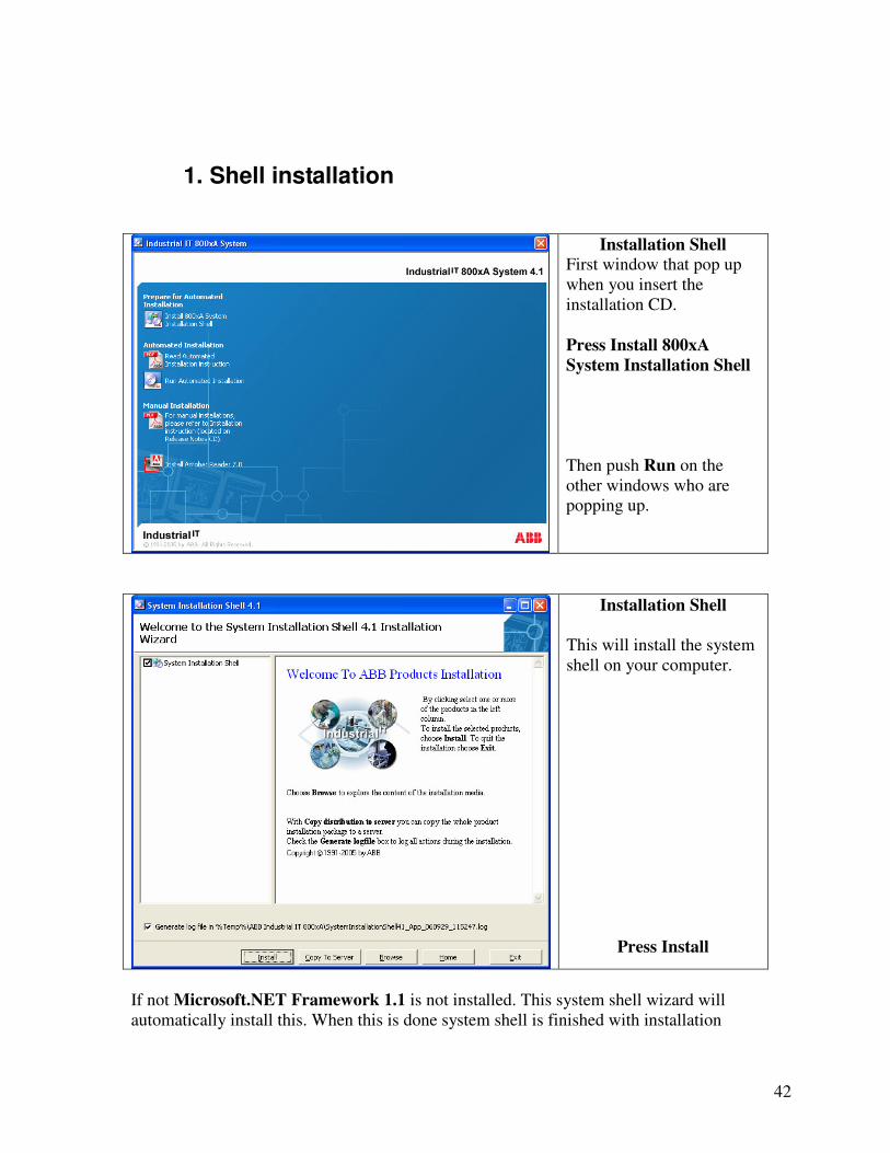
1. Shell installation
Installation Shell
First window that pop up when you insert the installation CD. Press Install 800xA
System Installation Shell
Then push Run on the other windows who are popping up.
Installation Shell
This will install the system shell on your computer.
Press Install
If not Microsoft.NET Framework 1.1 is not installed. This system shell wizard will automatically install this. When this is done system shell is finished with installation

43
2. Automated installation
Automated Installation
Press Run Automated
Installation
System Planner
This is the system planner. It will make the system you want for your network/computers.
Press Next

44
Choose Medium
Choose CD/DVD and push DVD button in this window

45
System planner wizard
Press Next
Windows
Here you can choose to use computer with Windows installed or if you want to install windows. If you choose to use preinstalled Windows read the System Installation guide for prerequisites before installing the software. We have used blank pc’s This option makes a silent installation of Windows on c:\
Press Next

46
Nodes
The wizard prompts you to choose a node setup. We have used single nodes, this creates the entire system on one computer.
Click for Single
Engineering Node
Press Next
Connectivity
Choose the device connectivity. In this system there is only the AC 800M.
Press Next

47
Field bus
There is no usage of field bus.
Press Next
Workgroup/Domain
In this system we use workgroups.
Press Next

48
Summary
Press Next
Installation
Press Next

49
System Configuration
Choose workgroup, service account, password(Narvik8515) and system description.
Press Next
Summary
Use the default settings on all but password. Choose an easier password. We have used abb here.
Press Next

50
Node Name
Write in the name you want to use for your node/nodes
Press advanced
If you want to change the IP-adress of the node/nodes. This is not necessary.
Press Next
System configuration IP
Mark the box as shown in figure.
Press Next

51
System configuration IP
This will show the IP-address for the node.
Press Next
Summary
Press Next

52
Setup Package
Choose where to store the package. Use a diskette.
Press Next
Setup Package
Press Next

53
Setup Package
For information about the setup package click on the link in the window.
Press Next
Finished
You have now completed the System Planner and are ready to start with the installation of Industrial IT.
Press Finish

54
Computers without Windows
If you are using computer without Windows, or want to reinstall Windows you have to choose this in the System Planner. To do a silent installation insert the Windows CD and the diskette created in System Planner. This will install Windows automatically with the needed configurations on your local hard drive (c:\). NB: Silent installation will format all data on local hard drive (c:\) Installing Windows with the help of the disk you have created in System Planner is the safest way of installing the system. This is because most of the settings needed by Industrial IT are set automatically. When using a pre-installed Windows there are a lot of requisites that have to be done to your system. These are described in the System Installation book.

55
3. Industrial IT Single node installation guide The installation of Industrial IT on a computer is self-explaining. We have done a single node installation and created an installation guide. It is very important that you read the information given in each step, and that you have patience with each step. If you rush trough the installation and don’t let each step finish it might compromise the rest of the installation. Required assets for installing Industrial IT on a computer
- Windows XP Professional CD - CD/DVD Package from ABB - Administrator rights on the computer - Microsoft Word and Excel 2003 or newer - Diskette with a system created in System Planner - Turn off Windows Firewall and other firewalls that are included in some virus
programs. - Download all hot fixes for your OS from Windows update on the Internet.
This must be done to have a stable and safe OS before you do anymore installation. Note: This can only be done if you are using computers with pre-installed Windows. If you are using a blank computer you will be prompted to install hot-fixes during the installation. This should be done.
If the installation should crash there is two ways of starting it again.
- Restart PC, and the installation process should continue. - The other way is to manually restart it as shown in figure below.
- Start - Programs - ABB industrial IT 800xA System - System Installation Shell -Continue System installation

56
Manual start of installation, this requires a System Planner diskette
- Start - Programs - ABB industrial IT 800xA System - System Installation Shell - Setup a new system
Manually Installation
Start
Manually Installation
Start
Click on Browse

57
Manually Installation Start Browse after the stored installed package. File ending *.cct
Press Next
Manually Installation Start Example: *.cct file stored on floppy A:\
Press Next

58
Automated installation, this requires a System Planner diskette.
Installation Start
This is the start of the installation of Industrial It on your computer. This will automatically start when you have done a silent Windows installation.
Press Next
Installation Wizard
The wizard shows what is about to be done.
Press Next

59
Network Settings
On the installation the network settings from the diskette will be used.
Press Next
Network Settings
Shows computer name and network settings.
Press Next

60
Network Checklist
Press Next
Network Checklist
Press Next

61
Restart
Finish
Installation
Press Next

62
Installation Wizard
Press Next
Windows Components
Press Next

63
Checklist Windows
Press Next
Checklist Windows
Press Next

64
Restart
Press Next
Installation Wizard
Press Next

65
Choosing Workgroup
Here you choose the workgroup you want to use.
Press Next
Checklist Windows
Press Next

66
Checklist Windows
Press Next
Restart
Press Next

67
Installation Wizard
Press Next
Add Groups
Creating the groups used in the 800xA program. Use the default settings.
Press Next
68
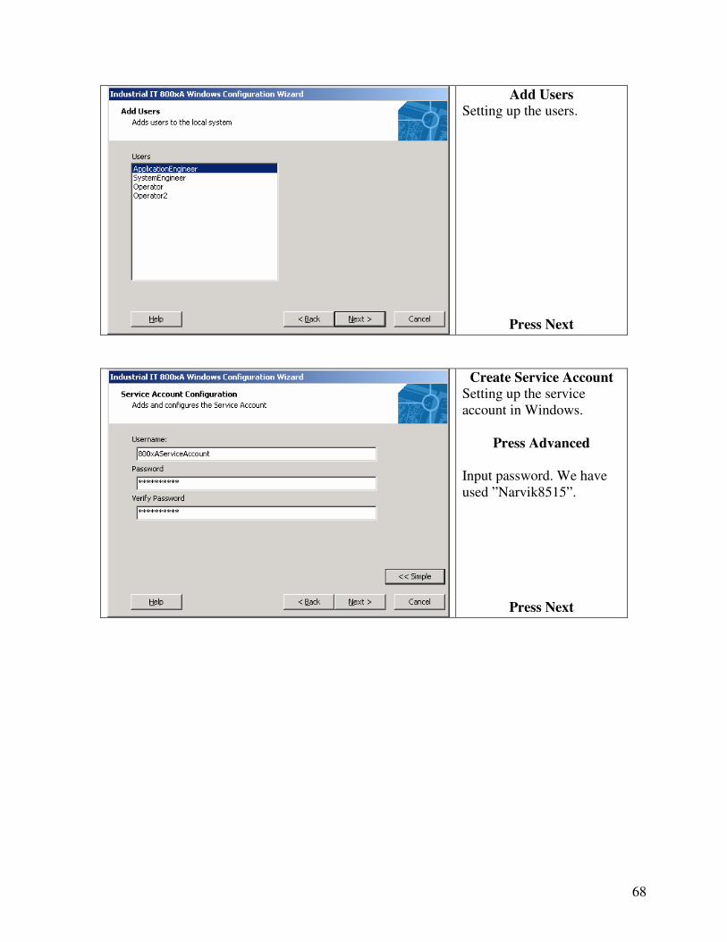
Add Users
Setting up the users.
Press Next
Create Service Account
Setting up the service account in Windows.
Press Advanced
Input password. We have used ”Narvik8515”.
Press Next

69
Checklist Windows
Press Next
Checklist Windows
Press Next
Insert the IIT800xA-41-1 DVD#1 in the DVD-rom.
Press OK

70
Installation Wizard
Press Next
System Checker
Gives you general information about the system. Also checks if you have the needed administrator rights.
Press Next

71
System Checker
Checks if your PC satisfy the requirements.
Press Next
System Checker Checks if needed programs are installed.
Press Install
This has to be done until all required programs are installed.
Press Next
Restart the PC

72
Installation Wizard
Press Next
Installation Wizard
Press Next

73
Check user rights
Press Next
Check hardware
Press Next

74
System Checker
Checks if the Windows components where installed.
Press Install
If there is a program missing, press install on it.
Press Next
System Checker
Checks if 3rd programs are installed.
Press Install
Install the programs needed.
Press Info
This will give additional information on the 3rd party programs needed.

75
WMI SNMP Provider
This message appears when pressing info. Follow this to install WMI SNMP.
WMI SNMP Provider
Mark the “Management and..” as shown in the figure.
Press Details

76
WMI SNMP Provider
Mark the checkbox as shown in the figure.
Press OK
Press Next
When Windows Component Wizard window opens. This will install the component.
System Checker
Press Next
When all 3rd party programs have been installed1.
1 Visual Basic 6.0 does not need to be installed at this point.

77
System Checker
Displays the installation report.
Press Finish
Backup
We have chosen not do make a backup in the installation.
Press Skip
78
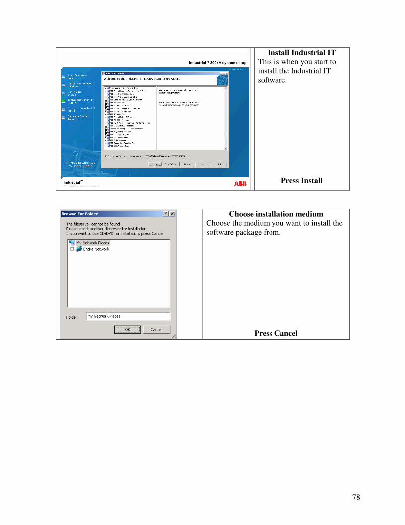
Install Industrial IT
This is when you start to install the Industrial IT software.
Press Install
Choose installation medium
Choose the medium you want to install the software package from.
Press Cancel

79
Information Box
Press OK
Installation
Write the password you have chosen in the password block.
Press Next

80
Installation
Settings that will be executed.
Press Next
Installation
Press Next

81
Installation
The rest of the steps are automated. When installation is complete, do a restart of the computer. The installation takes time and you should not restart the computer or start any other programs while install.

82
Appendix VI. Post installation After system installation has been done, your new system must be configured on your computer. This is a walkthrough of what is necessary to do in the post installation. Open Post installation document file [6]. Follow this instruction and start Configuration
wizard from the Start menu as shown in Figure 22.
Figure 22 Configuration Wizard start
Configuration wizard window will pop up, as shown in Figure 23
1. Chose Create system, see Figure 23. After choosing your configuration options the system will configure itself with your options. This configuration will take approximately 35 minutes. Do nothing on your computer while this is being installed.
2. Check that connectivity server is running. 3. Check that firmware version in AC 800M controller is similar to the version in the
program Control builder M professional.
Figure 23 Configuration Wizard