Installation and commissioning manual REL 521*2.3 Line ... · PDF fileREL 521*2.3 Line...
236
© ABB Automation Products AB 2001 Substation Automation Division Installation and commissioning manual REL 521*2.3 Line distance protection terminal About this manual DocID: 1MRK 506 070-UEN Issue date: June 2001 Status: New Version: 2.3 Revision: 00
Transcript of Installation and commissioning manual REL 521*2.3 Line ... · PDF fileREL 521*2.3 Line...

© ABB Automation Products AB 2001Substation Automation Division
Installation and commissioning manualREL 521*2.3
Line distance protection terminal
About this manualDocID: 1MRK 506 070-UEN
Issue date: June 2001Status: NewVersion: 2.3Revision: 00

COPYRIGHT
WE RESERVE ALL RIGHTS TO THIS DOCUMENT, EVEN IN THE EVENT THAT A PATENT IS ISSUED AND A DIFFERENT COMMERCIAL PROPRIETARY RIGHT IS REGISTERED. IMPROPER USE, IN PARTICULAR REPRODUCTION AND DIS-SEMINATION TO THIRD PARTIES, IS NOT PERMITTED.
THIS DOCUMENT HAS BEEN CAREFULLY CHECKED. IF THE USER NEVERTHELESS DETECTS ANY ERRORS, HE IS ASKED TO NOTIFY US AS SOON AS POSSIBLE.
THE DATA CONTAINED IN THIS MANUAL IS INTENDED SOLELY FOR THE PRODUCT DESCRIPTION AND IS NOT TO BE DEEMED TO BE A STATEMENT OF GUARANTEED PROPERTIES. IN THE INTERESTS OF OUR CUSTOMERS, WE CON-STANTLY SEEK TO ENSURE THAT OUR PRODUCTS ARE DEVELOPED TO THE LATEST TECHNOLOGICAL STAN-DARDS. AS A RESULT, IT IS POSSIBLE THAT THERE MAY BE SOME DIFFERENCES BETWEEN THE HW/SW PRODUCT AND THIS INFORMATION PRODUCT.
Manufacturer:
ABB Automation Products ABSubstation Automation DivisionSE-721 59 VästeråsSwedenTel: +46 (0) 21 34 20 00Fax: +46 (0) 21 14 69 18Internet: http://www.abb.se

Contents
PageChapter
Chapter 1 Introduction ..................................................................... 1
Introduction to the installation and commissioning manual ................. 2About the complete set of manuals to a terminal............................ 2About the installation and commissioning manual.......................... 3Intended audience .......................................................................... 3Related documents......................................................................... 4Revision notes ................................................................................ 4
Chapter 2 Safety information........................................................... 5
Warning signs ...................................................................................... 6Caution signs ....................................................................................... 8Note signs............................................................................................ 9
Chapter 3 Overview ........................................................................ 11
Commissioning and installation overview .......................................... 12
Chapter 4 Unpacking and checking the terminal ........................ 13
Receiving, unpacking and checking .................................................. 14
Chapter 5 Installing the terminal ................................................... 15
Overview............................................................................................ 16Mounting the terminal ........................................................................ 17
Mounting in a 19-inch rack ........................................................... 18Mounting in a 19-inch rack with an additional box type RHGS..... 19Mounting in a flush or semi-flush installation ................................ 21Mounting on a wall ....................................................................... 24
Making the electrical connections...................................................... 26Connecting the CT circuits............................................................ 26Connecting the auxiliary power, VT and signal connectors .......... 26Connecting to protective ground................................................... 27Making the screen connection...................................................... 27
Installing the optical fibres ................................................................. 28Installing the communication cables .................................................. 29

Contents
Chapter 6 Checking the external circuitry .................................... 31
Overview............................................................................................ 32Checking the CT and VT circuits ....................................................... 33Checking the power supply................................................................ 34Checking the binary I/O circuits ......................................................... 35
Binary input circuits....................................................................... 35Binary output circuits .................................................................... 35
Chapter 7 Energising the terminal................................................. 37
Overview............................................................................................ 38Energising the terminal ...................................................................... 39Checking the self supervision signals ................................................ 40
Reconfiguring the terminal............................................................ 40Setting the terminal time ............................................................... 40Checking the self supervision function ......................................... 41Self supervision HMI data............................................................. 41
Chapter 8 Configuring the digital communication modules....... 43
Configuring the fibre optical modem .................................................. 44Configuring the short range fibre optical modem............................... 45Configuring the short range galvanic modem .................................... 49Configure the interface modules for V.36, X.21 and RS530 .............. 51Configuring the interface modules for G.703 co-directional............... 53
Chapter 9 Setting and configuring the terminal........................... 55
Overview............................................................................................ 56Entering settings through the local HMI ............................................. 57Downloading settings and configuration from a PC........................... 58
Establishing front port communication.......................................... 58Establishing rear port communication........................................... 58Downloading the configuration and setting files ........................... 60
Chapter 10 Establishing connection and verifying the SPA/IEC-communication.............................................................. 61
Entering settings ................................................................................ 62Entering SPA settings................................................................... 62Entering IEC settings .................................................................... 62
Verifying the communication.............................................................. 64Verifying SPA communication ...................................................... 64Verifying IEC communication........................................................ 64

Contents
Chapter 11 Verifying settings by secondary injection ................. 65
Overview............................................................................................ 66Preparing for test ............................................................................... 68
Overview....................................................................................... 68Preparing the connection to the test equipment ........................... 68Setting the terminal in test mode .................................................. 69Connecting test equipment to the terminal ................................... 69Verifying the connection and the analog inputs............................ 70Releasing the function(s) to be tested .......................................... 71Checking the disturbance report settings ..................................... 72
Automatic switch onto fault logic (SOTF)........................................... 74External activation of SOTF function ............................................ 74Automatic initiation of SOTF......................................................... 74Completing the test....................................................................... 74
Automatic reclosing function (AR) ..................................................... 75Preparing ...................................................................................... 76Checking the AR functionality....................................................... 77Checking the reclosing condition .................................................. 78Testing the multi-breaker arrangement......................................... 79Completing the test....................................................................... 79
Binary signal transfer to remote end (RTC) ....................................... 80Breaker failure protection (BFP) ........................................................ 81
Measuring the operate limit .......................................................... 81Verifying the retrip setting............................................................. 81Completing the test....................................................................... 82
Broken conductor check (BRC) ......................................................... 83Measuring the operate and time limit of set values ...................... 83
Communication channel Logic (CCHL) ............................................. 85Testing the time delayed operation for only one communications signal .............................................................. 85Testing the unblocking logic within each separate signal ............. 86Testing the simultaneous presence of two carrier receive signals ............................................................ 86Completing the test....................................................................... 86
Communication channel test logic (CCHT)........................................ 87Testing the logic ........................................................................... 87
Current circuit supervision (CTSU) .................................................... 88Current reversal and weak end infeed logic for distance protection (ZCAL) .............................................................. 89
Current reversal logic.................................................................... 89Weak end infeed logic .................................................................. 90Completing the test....................................................................... 91
Current reversal and weak end infeed logic for residual overcurrent protection (EFCA) ......................................................... 92
Testing the current reversal logic.................................................. 92Testing the weak-end-infeed logic ................................................ 92Completing the test....................................................................... 94
Dead line detection (DLD) ................................................................. 95Definite and inverse time-delayed residual overcurrent protection (TEF) ............................................................. 96

Contents
Checking the operate values of the current measuring elements ................................................. 96
Distance protection (ZMn)................................................................ 100Measuring the operate limit of set values ................................... 103Measuring the operate time of distance protection zones .......... 104Completing the test..................................................................... 104
Disturbance recorder (DRP) ............................................................ 105Event counter (CN) .......................................................................... 106Event function (EV) .......................................................................... 107Event recorder ................................................................................. 108Fault locator (FLOC) ........................................................................ 109Four step residual overcurrent protection (EF4) .............................. 111
Testing the direction measuring element.................................... 111Testing the current step 4. .......................................................... 111Testing the “Blocking at parallel transformer” function. .............. 115Testing the current step 1-3........................................................ 115Testing the Switch-onto-fault ..................................................... 117Completing the test..................................................................... 118
Fuse failure supervision (FUSE) ...................................................... 119Checking that the binary inputs and outputs operate as expected ............................................................ 119Measuring the operate value for the negative sequence function ................................................ 120Measuring the operate value for the zero sequence function..... 121Checking the operation of the du/dt, di/dt based function........... 122Completing the test..................................................................... 123
High speed binary output logic (HSBO) ........................................... 124HSBO- trip from communication logic......................................... 124HSBO- trip from the high-speed function (HS) ........................... 126HSBO- trip from the distance protection zone 1 function (ZM1) . 127Completing the test..................................................................... 128
Instantaneous overcurrent protection (IOC)..................................... 129Measuring the operate limit of set values ................................... 129Completing the test..................................................................... 130
Intercircuit bridging protection (TOVI) .............................................. 131Measuring the operate and time limit of set values .................... 131
Local acceleration logic (ZCLC)....................................................... 133Loss of voltage check (LOV)............................................................ 134
Measuring the operate limit of set values ................................... 134Monitoring of AC analogue measurements...................................... 136Monitoring of DC analogue measurements ..................................... 137Multiple command (CM)................................................................... 139Overload supervision (OVLD) .......................................................... 140
Measuring the operate and time limit of set values .................... 140Phase selection logic (PHS) ............................................................ 142
Measuring the operate limit of set values ................................... 144Pole discordance protection (PD) .................................................... 145Pole slip protection (PSP) ................................................................ 146
Measuring the operating characteristics ..................................... 146Testing the pole slip functionality................................................ 152Testing the additional functionality.............................................. 154Completing the test..................................................................... 155
Power swing detection (PSD) .......................................................... 156

Contents
Testing overview......................................................................... 157Testing the one-of-three-phase operation .................................. 157Testing the two-of-three-phase operation................................... 157Testing the tEF timer and functionality ....................................... 158Testing the tR1 timer .................................................................. 159Testing the tR2 timer .................................................................. 159Testing the block input................................................................ 160Completing the test..................................................................... 160
Power swing logic (PSL).................................................................. 161Testing the carrier send and trip signals..................................... 161Testing the influence of the residual overcurrent protection....... 162Controlling of the underreaching zone........................................ 163Completing the test..................................................................... 163
Pulse counter logic (PC) .................................................................. 164Radial feeder protection (PAP) ........................................................ 165
Testing the fast fault clearance................................................... 165Testing the delayed fault clearance............................................ 165Completing the test..................................................................... 166
Setting lockout (HMI) ....................................................................... 167Scheme communication logic for distance protection functions (ZCOM) .......................................................................... 168
Testing permissive underreach................................................... 168Testing permissive overreach..................................................... 169Testing blocking scheme ............................................................ 169Checking of unblocking logic ...................................................... 170Completing the test..................................................................... 170
Scheme communication logic for residual overcurrent protection (EFC) ......................................................... 171
Testing the directional comparison logic function ....................... 171Completing the test..................................................................... 172
Sensitive directional residual overcurrent protection (WEF1).......... 173Measuring the operate and time limit for set values ................... 174
Sensitive directional residual power protection (WEF2) .................. 175Measuring the operate and time limit of set values .................... 176
Setting group selector (GRP)........................................................... 177Single command (CD) ..................................................................... 178Stub protection (STUB).................................................................... 179
Measuring the operate limit of set values ................................... 179Synchrocheck (SYN) ....................................................................... 181
Testing the phasing function....................................................... 183Testing the synchrocheck........................................................... 184Testing the energizing check...................................................... 191Testing the voltage selection ...................................................... 194Completing the test..................................................................... 197
Thermal overload protection (THOL) ............................................... 198Measuring the operate and time limit of set values .................... 198
Time delayed overcurrent protection (TOC) .................................... 200Measuring the operate limit of set values ................................... 200Completing the test..................................................................... 201
Time delayed overvoltage protection (TOV) .................................... 202Measuring the operate and time limit of set values .................... 202Completing the test..................................................................... 202
Time delayed undervoltage protection (TUV) .................................. 203

Contents
Measuring the operate limit of set values ................................... 203Trip logic (TR) .................................................................................. 204
3ph operating mode.................................................................... 2041ph/3ph operating mode............................................................. 2041ph/2ph/3ph operating mode...................................................... 205Completing the test..................................................................... 206
Two step time delayed directional phase overcurrent protection (TOC3) ........................................................ 207
Measuring the operate and time limit for set values ................... 207Completing the test..................................................................... 209
Two step time delayed phase overcurrent protection (TOC2) ......... 210Measuring the operate and time limit for set values ................... 210Completing the test..................................................................... 211
Unbalance protection for capacitor banks (TOCC) .......................... 212Measuring the operate and time limit of set values .................... 212
Chapter 12 Verifying the internal configuration........................... 215
Overview.......................................................................................... 216Testing the interaction of the distance protection ............................ 217
Chapter 13 Testing the protection system ................................... 219
Overview.......................................................................................... 220Testing the interaction of the distance protection ............................ 221
Chapter 14 Checking the directionality......................................... 223
Overview.......................................................................................... 224Testing the directionality of the distance protection ......................... 225Testing the directional residual overcurrent protection .................... 227

About this chapter Chapter 1Introduction
Chapter 1 Introduction
About this chapter
This chapter introduces the user to the manual as such.
1

Introduction to the installation and commissioning manual
Chapter 1Introduction
es or on of
refer-l and
nfig-ters n
1 Introduction to the installation and commissioning manual
1.1 About the complete set of manuals to a terminal
The complete package of manuals to a terminal is named users manual (UM). The Us-ers manual consists of four different manuals:
The Application Manual (AM) contains descriptions, such as application and func-tionality descriptions as well as setting calculation examples sorted per function. The application manual should be used when designing and engineering the protection ter-minal to find out where and for what a typical protection function could be used. The manual should also be used when calculating settings and creating configurations.
The Technical Reference Manual (TRM) contains technical descriptions, such as function blocks, logic diagrams, input and output signals, setting parameter tables and technical data sorted per function. The technical reference manual should be used as a technical reference during the engineering phase, installation and commissioning phase and during the normal service phase.
The Operator´s Manual (OM) contains instructions on how to operate the protection terminal during normal service (after commissioning and before periodic maintenance tests). The operator´s manual could be used to find out how to handle disturbanchow to view calculated and measured network data in order to determine the reasa fault.
The Installation and Commissioning Manual (ICM) contains instructions on how toinstall and commission the protection terminal. The manual can also be used as aence if a periodic test is performed. The manual covers procedures for mechanicaelectrical installation, energising and checking of external circuitry, setting and couration as well as verifying settings and performing a directionality test. The chapand sections are organised in the chronological order (indicated by chapter/sectionumbers) the protection terminal should be installed and commissioned.
Applicationmanual
Technicalreference
manual
Installation andcommissioning
manual
Operator´smanual
en01000044.vsd
2

Introduction to the installation and commissioning manual
Chapter 1Introduction
”
1.2 About the installation and commissioning manual
The installation and commissioning manual contains the following chapters:
• The chapter “Safety information” presents warning and note signs, which the user should draw attention to.
• The chapter “Overview” gives an overview over the major task when installing and commissioning the terminal.
• The chapter “Unpacking and checking the terminal” contains instructions on how to receive the terminal.
• The chapter “Installing the terminal” contains instructions on how to install the ter-minal.
• The chapter “Checking the external circuitry” contains instructions on how to check that the terminal is properly connected to the protection system.
• The chapter “Energising the terminal” contains instructions on how to start-up the terminal.
• The chapter “Configuring the digital communication modules” contains instruc-tions on how to configure the communication modules such as modems, optical con-verters etc if included in the terminal.
• The chapter “Setting and configuring the terminal” contains instructions on how to download settings and configuration to the terminal.
• The chapter “Establishing connection and verifying the SPA/IEC-communication contains instructions on how to enter SPA/IEC settings and verifying the SPA/IEC communication.
• The chapter “Verifying settings by secondary injection” contains instructions on how to verify that each included function operates correctly according to the set val-ue.
• The chapter “Verifying the internal configuration” contains instructions on how verify that the terminal is properly configured.
• The chapter “Testing the protection system” contains instructions on how to test that the terminal is in contact with the primary system.
• The chapter “Checking the directionality” contains instructions on how to test di-rectional dependent functions, if included in the terminal.
1.3 Intended audience
1.3.1 General
The installation and commissioning manual is addressing the installation, commission-ing and maintenance personnel responsible for taking the protection into normal service and out of service.
3

Introduction to the installation and commissioning manual
Chapter 1Introduction
1.3.2 Requirements
The installation personnel must have a basic knowledge in handling electronic equip-ment. The commissioning and maintenance personnel must be well experienced in us-ing protection equipment, test equipment, protection functions and the configured functional logics in the protection.
1.4 Related documents
1.5 Revision notes
Documents related to REL 521*2.3 Identity number
Operator’s manual 1MRK 506 068-UEN
Installation and commissioning manual 1MRK 506 070-UEN
Technical reference manual 1MRK 506 069-UEN
Application manual 1MRK 506 111-UEN
Technical overview brochure 1MRK 506 067-BEN
Revision Description
2.3-00 First revision
4

About this chapter Chapter 2Safety information
Chapter 2 Safety information
About this chapter
This chapter contains safety information. Warning signs are presented which attend the user to be careful during certain operations in order to avoid human injuries or damage to equipment
5

Warning signs Chapter 2Safety information
1 Warning signs
Warning!
Strictly follow the company and country safety regulations. Working in a high voltageenvironment requires serious approach to avoid human injuries and damage to equip-ment.
Warning!
Do not touch circuitry during operation. Potentially lethal voltages and currents arepresent.
Warning!
Always avoid to touch the circuitry when the cover is removed. The product containselectronic circuitries which can be damaged if exposed to static electricity (ESD). Theelectronic circuitries also contain high voltage which is lethal to humans.
Warning!
Always use suitable isolated test pins when measuring signals in open circuitry. Poten-tially lethal voltages and currents are present.
Warning!
Never connect or disconnect a wire and/or a connector to or from a terminal duringnormal operation. Hazardous voltages and currents are present that may be lethal. Op-eration may be disrupted and terminal and measuring circuitry may be damaged.
Warning!
Always connect the terminal to protective ground, regardless of the operating condi-tions. This also applies to special occasions such as bench testing, demonstrations andoff-site configuration. Operating the terminal without proper grounding may damageboth terminal and measuring circuitry, and may cause injuries in case of an accident.
6

Warning signs Chapter 2Safety information
ithmage
con-
Warning!
Never disconnect a secondary connection of current transformer circuit without short-circuiting the transformer’s secondary winding. Operating a current transformer wthe secondary winding open will cause a massive potential build-up that may dathe transformer and may cause injuries to humans.
Warning!
Never unmount the front or back cover from a powered terminal or from a terminal nected to powered circuitry. Potentially lethal voltages and currents are present.
7

Caution signs Chapter 2Safety information
2 Caution signs
Caution!
Always transport modules using certified conductive bags. Always handle modules us-ing a conductive wrist strap connected to protective ground and on a suitable antistaticsurface. Electrostatic discharge (ESD) may cause damage to the module.
Caution!
Do not connect live wires to the terminal. Internal circuitry may be damaged
Caution!
Always use a conductive wrist strap connected to protective ground when replacingmodules. Electrostatic discharge (ESD) may damage the module and terminal circuit-ry.
Caution!
Take care to avoid electrical shock if accessing wiring and connection terminals wheninstalling and commissioning.
8

Note signs Chapter 2Safety information
. Be
times
e set-
3 Note signs
Note!
Changing the active setting group will inevitably change the terminal’s operationcareful and check regulations before making the change.
Note!
The protection assembly is designed for a maximum continuous current of four rated value.
Note!
Activating the setting lockout function, which prevents unauthorised changes of thtings, without proper configuration may seriously affect the terminal’s operation.
9

Note signs Chapter 2Safety information
10

About this chapter Chapter 3Overview
Chapter 3 Overview
About this chapter
This chapter introduces the user to the installation and commissioning tasks.
11

Commissioning and installation overview Chapter 3Overview
1 Commissioning and installation overview
The settings for each function must be calculated before the commissioning task can start. A configuration, made in the configuration and programming tool, must also be available if the terminal does not have a factory configuration downloaded.
The terminal is unpacked and visually checked. It is preferably mounted in a cubicle or on a wall. The connection to the protection system has to be checked in order to verify that the installation was successful.
The installation and commissioning task starts with configuring the digital communica-tion modules, if included. The terminal can then be configured and set, which means that settings and a configuration has to be applied if the terminal does not have a factory configuration downloaded. Then the operation of each included function according to applied settings has to be verified by secondary injection. A complete check of the con-figuration can then be made. A conformity test of the secondary system has also to be done. When the primary system has been energised a directionality check should be made.
12

About this chapter Chapter 4Unpacking and checking the
terminal
Chapter 4 Unpacking and checking the terminal
About this chapter
This chapter contains instructions on how to receive the terminal.
13

Receiving, unpacking and checking Chapter 4Unpacking and checking the
terminal
1 Receiving, unpacking and checking
Procedure
1. Remove the transport casing.
2. Visually inspect the terminal.
3. Check that all items are included in accordance with the de-livery documents.
The user is requested to check that all software functions are in-cluded according to the delivery documents after the terminal has been energised.
4. Check for transport damages.
In case of transport damage appropriate action must be taken against the latest carrier and the nearest ABB office or representa-tive should be informed. ABB should be notified immediately if there are any discrepancies in relation to the delivery documents.
Store the terminal in the original transport casing in a dry and dust free place, if the terminal is not to be installed or commissioned immediately. Observe the environmental requirements stated in the technical data.
14

About this chapter Chapter 5Installing the terminal
Chapter 5 Installing the terminal
About this chapter
This chapter describes how to install the terminal.
15

Overview Chapter 5Installing the terminal
1 Overview
The mechanical and electrical environmental conditions at the installation site must be within permissible range according to the technical data of the terminal. Dusty, damp places, places liable to rapid temperature variations, powerful vibrations and shocks, surge voltages of high amplitude and fast rise time, strong induced magnetic fields or similar extreme conditions should be avoided.
Sufficient space must be available in front of and at rear of the terminal to allow access for maintenance and future modifications. Flush mounted terminals should be mounted so that terminal modules can be added and replaced without excessive demounting.
16

Mounting the terminal Chapter 5Installing the terminal
2.1.
the one flush e top
2 Mounting the terminal
A suitable mounting kit must be available. Mounting kits contains all parts needed in-cluding screws and assembly instructions. The following mounting kits are available:
• 19-inch rack mounting kits, 1/2, 3/4 and 1/1 terminal width variants. See section
• Side-by-side mounting kit. See section 2.2.
• Flush mounting kit. See section 2.3.
• Semi-flush mounting kit. See section 2.3.
• Wall mounting kit. See section 2.4.
Most of the REx 5xx terminals can be rack, flush, semi-flush or wall mounted withuse of different mounting kits. An additional box of type RHGS can be mounted toside of a 1/2 or 3/4 terminal. The 1/1 of 19-inches wide terminal can not be semi-mounted due to that the mounting angles will cover the ventilating openings at thand bottom parts.
17

Mounting the terminal Chapter 5Installing the terminal
2.1 Mounting in a 19-inch rack
Figure 1: 19-inch rack mounting
PosNo Description
1 and 4 Mounting angle
2 and 3 TORX T20 screws
(98000037)
1
2
3
4
18

Mounting the terminal Chapter 5Installing the terminal
Procedure
1. Carefully fasten the mounting angles to the sides of the termi-nal.
Use the TORX T20 screws available in the mounting kit.
2. Place the terminal assembly in the rack.
3. Fasten the mounting angles with appropriate screws.
2.2 Mounting in a 19-inch rack with an additional box type RHGS
Make sure a side-by-side mounting kit and a suitable 19-inch rack mounting kit are available before proceeding.
Assemble the two terminals by using a side-by-side mounting kit. Then mount the brackets and install the assembled terminals in the rack as described in section 2.1.
19

Mounting the terminal Chapter 5Installing the terminal
Figure 2: Side-by-side assembly
PosNo Description
1 and 3 Side-by-side mounting plate
2 and 4 Screws (TORX T20)
5 Mounting angle
xx00000097.ai
2
1
3
4
5
5
20

Mounting the terminal Chapter 5Installing the terminal
Procedure
1. Place the two terminals next to each other on a flat surface.
2. Fasten a side-by-side mounting plate (PosNo 1).
Use four of the delivered screws.
3. Carefully turn the two terminals up-side down.
4. Fasten the second side-by-side mounting plate.
Use the remaining four screws.
5. Follow the instructions in section 2.1 to mount the mounting angles (PosNo 5) and install the side-by-side assembly in the rack.
2.3 Mounting in a flush or semi-flush installation
Make sure a flush or semi-flush mounting kit is available before proceeding.
The procedure for flush and semi-flush mounting is mainly the same. In semi-flush mounts a distance frame is added. The delivered mounting seal is only necessary to ful-fill IP 54.
21

Mounting the terminal Chapter 5Installing the terminal
Figure 3: Flush and semi-flush mounting
PosNo Description
1 Sealing strip
2 Distance frame (only for semi-flush)
3 Sealing strip for distance frame (only for semi-flush)
4 Side holder
5 Groove
6 Locking screw (TORX T10)
xx00000129.eps
12
3
4
56
22

Mounting the terminal Chapter 5Installing the terminal
Procedure
1. Cut the sealing strip in appropriate lengths.
The strip is delivered with the mounting kit. In the semi-flush mounting kit two strips are delivered, one for the terminal and one self-adhering for the distance frame. The length of the strip is enough for the largest available terminal.
Cut the strip into four, one part for each side of the terminal. When cutting, make sure no gaps will be present between each part. Pref-erably, seal joints should be at the corners (posNo 1).
Repeat the procedure for the self-adhering strip which are to be ad-hered to the distance frame.
2. Dispose the strip remains.
The remains should be source separated as soft plastic.
3. Carefully press the cut strips into the front panel groove.
4. Adhere the cut strips (posNo 3) to the edge of the distance frame (posNo 2).
semi-flush mounting only.
5. Make a panel cut-out.
See the Technical reference manual for cut-out dimensions.
6. Insert the terminal into the cut-out.
7. Add and lock the side holders (PosNo 4) to the terminal.
Thread a side holder into the groove (posNo 5) at the back end of the terminal. Insert and lightly fasten the locking screw (posNo 6). Next, thread a side holder on the other side of the terminal, and lightly fasten its locking screw.
Repeat this with the remaining two side holders.
Note!
Flush or semi-flush mount cannot be used for side-by-side mounted terminals whenIP 54 must be fulfilled.
23

Mounting the terminal Chapter 5Installing the terminal
8. Lock the terminal to the cut-out.
Firmly tighten the locking screws. It is important that all four side holder locking screws are tightened the same in order to maintain a good and even seal in IP 54 environments.
2.4 Mounting on a wall
The mounting bars are prepared for adding DIN-rails or equivalent above and below the mounted terminal. If used, make sure all necessary parts such as rails and terminal blocks are available before starting. Make sure the wall mounting kit is available.
Figure 4: Wall mounting
PosNo Description
1 Mounting bar
2 Side plate
xx00000130.eps
1
2
24

Mounting the terminal Chapter 5Installing the terminal
2.4.1 Mounting the terminal on a wall
Procedure
1. Mount the bars (posNo 1) onto the wall.
See the Technical reference manual for measurements.
Depending on the wall different preparations may be needed, like drilling and inserting plastic or expander plugs (concrete/plaster-board walls) or threading (metal sheet wall).
2. Mount the DIN-rail(s) on the mounting bars.
3. Mount the terminal blocks on the DIN-rail(s).
It is much easier to do this without the unit in place.
4. Make all electrical connections to the terminal blocks.
It is much easier to do this without the unit in place.
5. Mount the side plates (posNo 2) to the terminal.
6. Mount the terminal to the mounting bars.
2.4.2 Preparing a wall mounted terminal for electrical installation
Procedure
1. Remove all screws from one side plate.
2. Remove two screws from the other side plate.
3. Careful swing the terminal out from the wall.
See figure 5.
xx99000287
Figure 5: View from above over a wall mounted terminal that is prepared for electrical connection.
25

Making the electrical connections Chapter 5Installing the terminal
ure able. sepa-
nol-
3 Making the electrical connections
Always make sure established guidelines for this type of terminal is followed during in-stallation. When necessary use screened twisted-pair cables to minimize susceptibility. Otherwise use any kind of regular nonscreened tinned RK cable or equivalent.
When using screened cabling always use 360° full screen cable bushings to ensscreen coupling. Ensure that all signals of a single circuit are in the same single cAvoid mixing current and voltage measuring signals in the same cable. Also use rate cables for control and measuring circuits.
3.1 Connecting the CT circuits
CTs are connected using back-side mounted screw connectors.
Use a solid conductor with a cross section area between 2.5-6 mm2 (AWG20-10) or a stranded conductor with a cross section area between 2.5-4 mm2.
3.2 Connecting the auxiliary power, VT and signal connectors
Auxiliary power, VTs and signals are connected using COMBICON (Phoenix techogy) plug-in screw connectors.
Procedure
1. Connect signals to the COMBICON plug.
2. Plug the connector to the corresponding back-side mounted receptable.
3. Lock the plug to the receptable by fastening the lock screws.
Use a solid or stranded conductor with a cross section area be-tween 0.5-2.5 mm2 (AWG24-12). Use a ferrule with plastic collar to connect two conductors, cross section area between 0.5-1.5 mm2 (AWG20-18).
Note!
Screened and twisted pair cables is a requirement for galvanic communications in ap-plication with 56/64 kbit/s. The screen must be earthed at both sides of a cable.
26

Making the electrical connections Chapter 5Installing the terminal
3.3 Connecting to protective ground
Connect the unit to the grounding bar of the cubicle with a green/yellow conductor, cross section at least 1.5 mm2 (AWG18), connected to the protective ground connector at the back of the terminal.
3.4 Making the screen connection
When using screened cables always make sure screens are grounded and connected in according to applicable engineering methods. This may include checking for appropri-ate grounding points near the terminal, for instance, in the cubicle and/or near the source of measuring. Ensure that ground connections are made with short (max. 10 cm) con-ductors of an adequate cross section, at least 6 mm2 (AWG18) for single screen connec-tions.
en01000189.vsd
Source
Load
Signal Cable
Load
Source
27

Installing the optical fibres Chapter 5Installing the terminal
4 Installing the optical fibres
Connectors are generally color coded; connect blue or dark grey cable connectors to blue or dark grey (receive) back-side connectors. Connect black or grey cable connec-tors to black or grey (transmit) back-side connectors.
Fiber optical cables are sensitive to handling. Do not bend too sharply. The minimum curvature radius is 15 cm for plastic fibers and 25 cm for glass fibers. If cable straps are used, apply with loose fit.
Caution!
Always hold the connector, never the cable, when connecting or disconnecting opticalfibres. Do not twist, pull or bend the fibre. Invisible damage may increase fibre damp-ing thus making communication impossible.
28

Installing the communication cables Chapter 5Installing the terminal
5 Installing the communication cables
When using galvanic connection between protection terminal and communication equipment or point to point galvanic connection between two protection terminals it is essential that the cable installation is carefully done. This is true regardless of type of module used, G.703, V.36, short range galvanic etc., only the possible length of the ca-ble differs. The factors that must be taken into account is the susceptibility for noise dis-turbance, due to that the levels of the communication signal are very low.
For best result a cable with twisted pairs and double screens should be used, one screen for each twisted pair and one surrounding all pairs. Each signal shall utilizing its own twisted pair as in figure 6. The screen for each separate pairs shall be connected to in-ternal screen or ground connection of equipment, if available, or in other case connected to earth close to the equipment at the sending end for the signal. At receiving end the screen shall be left floating, that is, not connected to earth.
The outer screen surrounding all pairs shall be connected to a solid earth at each end close to the equipment.
Figure 6: Communication cable installation
Cc Communication cable
Lc Line connector
Rx Receive input
Sc Screen (or earth/ground) connection
Tx Transmit output
en01000160.vsd
Rx
Tx
Sc
Lc
Tx
Rx
Sc
LcCc
29

Installing the communication cables Chapter 5Installing the terminal
Note also that recommendation about cable lengths given for modules according ITU/EIA interface, not short range galvanic module, are under the assumption that the two equipment, protection terminal and communication, are within the same building and that the earthing system of the building is well carried out. It also presumes that the en-vironment is relatively free from electromagnetic noise.
30

About this chapter Chapter 6Checking the external circuitry
and
Chapter 6 Checking the external circuitry
About this chapter
This chapter describes what to check and which checks that should be made to ensure a correct connection to the external circuitry, such as auxiliary power supply, CT’sVT’s. These checks must be made with the protection terminal de-energised.
31

Overview Chapter 6Checking the external circuitry
1 Overview
The user must check the installation which includes verifying that the terminal is con-nected to the other parts of the protection system. This is done with the terminal and all connected circuits de-energised.
32

Checking the CT and VT circuits Chapter 6Checking the external circuitry
The
om -neu-he neu-
2 Checking the CT and VT circuits
Check that the wiring is in strict accordance with the supplied wiring diagram.
Test the circuitry. The following tests are recommended:
• Polarity check.
• CT circuit current measurement (primary injection test).
• Grounding check.
The polarity check verifies the integrity of the circuits and the phase relationship.check should be performed as close as possible to the terminal.
The primary injection test verifies the CT ratio and the wiring all the way through frthe primary system to the terminal. Injection must be performed for each phase-totral circuit and each phase-to-phase pair. In each case currents in all phases and ttral line are measured.
Note
Do not continue further until any errors are corrected.
33

Checking the power supply Chapter 6Checking the external circuitry
3 Checking the power supply
Check that the value of the auxiliary supply voltage remains within the permissible range under all operating conditions. Check that the polarity is correct according to the technical data on the front plate on the terminal.
34

Checking the binary I/O circuits Chapter 6Checking the external circuitry
heck inal’s
4 Checking the binary I/O circuits
4.1 Binary input circuits
Preferably, disconnect the binary input connector from the binary input cards. Check all connected signals so that both input level and polarity are in accordance with the termi-nal’s specifications.
4.2 Binary output circuits
Preferably, disconnect the binary output connector from the binary output cards. Call connected signals so that both load and polarity are in accordance with the termspecifications.
35

Checking the binary I/O circuits Chapter 6Checking the external circuitry
36

About this chapter Chapter 7Energising the terminal
Chapter 7 Energising the terminal
About this chapter
This chapter describes the start up sequence and what to check after the terminal has been enerigsed.
37

Overview Chapter 7Energising the terminal
1 Overview
Before the procedures in this chapter can be carried out the connection to external cir-cuitry must have been checked which ensures that the installation was made correctly.
The user must energise the power supply to the terminal to start it up. This could be done in a numerous of ways, from energising a whole cubicle to energising a single ter-minal. The user should reconfigure the terminal to activate the hardware modules in or-der to enable the self supervision function detect eventual hardware errors. Then the terminal time must be set. The self supervision function should also be checked to ver-ify that the terminal unit operates properly. The user could also check the software ver-sion, the terminals serial number and the installed modules and their ordering number to ensure that the terminal is according to delivery and ordering specifications.
38

Energising the terminal Chapter 7Energising the terminal
fter ady’.
D vision
2 Energising the terminal
When the terminal is energised the window on the local HMI remains dark. After 10 seconds the green LED starts flashing and after approximately 30 seconds the window lights up. After another 10 seconds the window displays ‘Terminal Startup’ and aabout 30 seconds the main menu is displayed. The upper row should indicate ‘ReA steady green light indicates a successful startup.
If the upper row in the window indicates ‘Fail’ instead of ‘Ready’ and the green LEis flashing an internal failure in the terminal has been detected. See the self superfunction in this chapter to investigate the fault.
After startup the appearance of the local HMI should be as shown in figure 7.
Figure 7: Example of the local HMI for, in this example, REL 531.
en00000422.vsd
E
C
ReadyREL 531 Ver 2.3C=QuitE=Enter menu
Start Trip
Push buttons
green yellow red
LEDs
Liquid Crystal Displayfour rows16 characters/row
Optical connectorfor local PC
39

Checking the self supervision signals Chapter 7Energising the terminal
3 Checking the self supervision signals
3.1 Reconfiguring the terminal
I/O modules configured as logical I/O modules (BIM, BOM, IOM, DCM, IOPSM or MIM) are supervised. Not configured I/O modules are not supervised.
Each logical I/O module has an error flag that is set if anything is wrong with any signal or the whole module. The error flag is also set when there is no physical I/O module of the correct type present in the connected slot.
Procedure
1. Browse to the ‘Reconfigure’ menu.
The Reconfigure menu is located in the local HMI under:
Configuration/I/O-modules/Reconfigure
2. Select ‘Yes’ and press ‘E’.
3.2 Setting the terminal time
This procedure describes how to set the terminal time.
1. Display the set time dialog.
Navigate the menus to:
Settings/Time
Press the E button to enter the dialog.
2. Set the date and time.
Use the Left and Right arrow buttons to move between the time and date values (year, month, day, hours, minutes and seconds). Use the Up and Down arrow buttons to change the value.
3. Confirm the setting.
Press the E button to set the calendar and clock to the new values.
40
Checking the self supervision signals Chapter 7Energising the terminal
3.3 Checking the self supervision function
3.3.1 Navigating the menus
This procedure describes how to navigate the menus in order to find the reason of an internal failure when indicated by the flashing green LED of the HMI module.
1. Display the self supervision menu.
Navigate the menus to:
TerminalReport
SelfSuperv
2. Scroll the supervision values to identify the reason of the fail-ure.
Use the Left and/or Right arrow buttons to scroll between values.
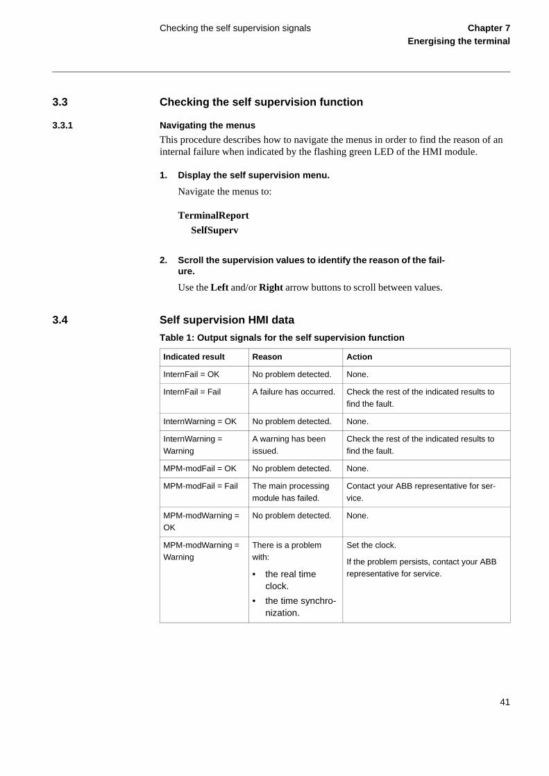
3.4 Self supervision HMI data
Table 1: Output signals for the self supervision function
Indicated result Reason Action
InternFail = OK No problem detected. None.
InternFail = Fail A failure has occurred. Check the rest of the indicated results to
find the fault.
InternWarning = OK No problem detected. None.
InternWarning =
Warning
A warning has been
issued.
Check the rest of the indicated results to
find the fault.
MPM-modFail = OK No problem detected. None.
MPM-modFail = Fail The main processing
module has failed.
Contact your ABB representative for ser-
vice.
MPM-modWarning = OK
No problem detected. None.
MPM-modWarning = Warning
There is a problem with:
• the real time clock.
• the time synchro-nization.
Set the clock.
If the problem persists, contact your ABB representative for service.
41

Checking the self supervision signals Chapter 7Energising the terminal
ADC-module = OK No problem detected. None.
ADC-module = Fail The A/D conversion module has failed.
Contact your ABB representative for ser-vice.
Slot04BIM1 = Fail
(Example data, se fol-lowing section for details)
I/O module communi-cation has failed.
Check that the I/O module has been config-ured and connected to the IOP1- block.
If the problem persists, contact your ABB representative for service.
RealTimeClock = OK No problem detected. None.
RealTimeClock = Warning
The real time clock has been reset.
Set the clock.
TimeSync = OK No problem detected. None.
TimeSync = Warning No time synchroniza-tion.
Check the synchronization source for prob-lems.
If the problem persists, contact your ABB
representative for service.
Indicated result Reason Action
42

About this chapter Chapter 8Configuring the digital
communication modules
Chapter 8 Configuring the digital communication modules
About this chapter
This chapter contains instructions on how to configure the digital communication mod-ules, such as galvanic and optical modems.
43

Configuring the fibre optical modem Chapter 8Configuring the digital
communication modules
als as a
tial
and
1 Configuring the fibre optical modem
Two different levels of optical output power can be set on the HMI under:
Configuration/TerminalCom/RemTermCom/OptoPower
For the optical module, the optical output power has to be set according to the attenua-tion of the fibre optic link.
For multimode fibres:
• If the attenuation is less than 6 dB, use Low setting
• If the attenuation is higher than 10 dB, use High setting
• If the attenuation is between 6 and 10 dB, use either High or Low setting
For single-mode fibres:
• If the attenuation is higher than 5 dB, use High setting
• If the attenuation is between 0 and 5 dB, use either High or Low setting
To achieve the best operation, the optical communication modules at both terminmust be synchronised. To fulfil this, one terminal acts as a Master and the other Slave. This is set under:
Configuration/TerminalCom/RemTermCom/CommSync
This setting should not be mixed up with the Master-Slave setting for the differenfunction.
When communicating with FOX20 or FOX6Plus, the setting should be Slave.
When operating over dedicated fibres the setting shall be Master at one terminal Slave at the other.
44

Configuring the short range fibre optical modem
Chapter 8Configuring the digital
communication modules
2 Configuring the short range fibre optical modem
No setting is available for the short range fiber optical modem on the HMI. There are however some that can be made on a DIP-switch located behind the cover around the fibre optic connectors at the back of the terminal according to figure 8. After the fibres has been disconnected, if attached, the cover plate can be removed just by pulling at the middle of the cover plate.
Figure 8: Setting and indications for short range optical modem
Switch 3 and 4 are used to set the source of timing. The function is according to setting of timing signal, table 2. When using the modem for optical point-to-point transmission, one modem should be set for locally created timing and the other for timing recovered from received signal. When the modems are communicating with a transceiver 21-15X or 16X the modems shall be set for timing recovered from received optical signal, see setting of timing signal.
Note!
If handled carefully the cover plate can be removed also with the fibres attached.
Fibre opticconnectors
Coverplate
On Off
TXDCTSRTSMALASync
RXDDSRDCDRALOSync
1234
Reset
xx00000552.vsd
45

Configuring the short range fibre optical modem
Chapter 8Configuring the digital
communication modules
The module can also synchronise received data with the send clock. This is not normal-ly necessary in this application. Synchronisation ON/OFF is controlled by switch 2, which shall normally be set in OFF position. When the module is set for synchronisa-tion (switch 2 = ON) switch 1 must be set in the position corresponding to the Sync LED that is brightest. If both have the same brightness the switch can be set in any position.
Table 2: Setting of timing signal
There are also some jumpers on the circuit board that has to be correctly set. One, S4 according to figure 10, is for changing the functionality between article number 1MRK 001 370-BA (marked 1MRK001471-BA) and 1MRK 001 370-DA (marked 1MRK001471-DA). The difference between these two is that the signal is inverted in one compared to the other.
The other jumper is S3 that has to be in bottom position, as marked in figure 10. If it is in top position the communication will not work. (In top position the transmit clock is supposed to be created in the CPU on the MPM module which is not possible). On JTAG/ISP there shall be no jumpers inserted.
Note!
After any change of settings, the modem has to be reset by the Reset button located be-low the DIP-switch.
Switch no. Function
3 4
OFF OFF Timing created by the modem
OFF ON Timing recovered from received optical signal
ON OFF Timing created by the differential function
ON ON No timing, the data transmission will not work
Note!
For a homogenous system, that is when the set up are identical at both terminals, thearticle number does not matter. When using a set up according to figure 9 only at oneend and for example a direct G.703 connection at the other end a short range fibre op-tical modem according to 1MRK 001 370-DA must be used. Using a short range fibreoptical modem according to 1MRK 001 370-BA will not work.
46

Configuring the short range fibre optical modem
Chapter 8Configuring the digital
communication modules
Figure 9: Multiplexed link, short range fibre optical connection
Figure 10: Jumper location on short range optical modem
The jumpers are accessible after the modem has been pulled out. This is done by first removing all green 18-pin connectors at the back, then remove all screws holding the back plate. After the back plate has been removed the modem can be pulled out.
xx00000542vsd
REx5xx<5km
Opticalfibres 21-15X/16X V.35/36 (15X)
X.21 (16X)G.703 (16X)
xx01000138.vsd
1
S3
S41MRK001471-BA
1MRK001471-DA
JTAG/ISP
Note!
Only pull out the modem not the whole double size Euro-card. After the jumper settingshas been changed put everything back in reverse order.
Note!
All electronic are sensitive to electrostatic discharge. Proper action must be taken atthe work place to avoid electrostatic discharge!
47

Configuring the short range fibre optical modem
Chapter 8Configuring the digital
communication modules
’s are
There are also some indication for supervision of the communication channel that can be seen when the cover around the fibre optic connectors is removed. These LEDfound above DIP-switch. The function of the LED’s are explained in table 3.Table 3: Indications
LED Colour Explanation
RTS Yellow Request to send
CTS Yellow Clear to send
DSR Yellow Data communication correct
DCD Yellow Detection of carrier signal
TXD Yellow Transmitted data
RXD Yellow Received data
RA Red Remotely detected problem with link
MA Red Memory function for problem with link
LO Green Link operation correctly
LA Red Locally detected problem with link
Sync Green Used when synchronisation is selected
48

Configuring the short range galvanic modem
Chapter 8Configuring the digital
communication modules
’s are
3 Configuring the short range galvanic modem
No setting is available for the short range galvanic modem on the HMI. There are how-ever some that can be made on a DIP-switch located behind the cover around the line connector at the back of the terminal according to figure 11. After the connector has been disconnected, if attached, the cover plate can be removed just by pulling at the middle of the cover plate. No settings are located on the circuit board.
Figure 11: Setting and indications for short range galvanic modem
Only switch 1 and 2 are used on the DIP-switch. The function is according to the setting of timing signal, see table 4. In normal operation switch 1 is set in ON position at one end and switch 2 is set ON at the other end. The rest of the switches is set OFF.
Table 4: Setting of timing signal
There are also some indication for supervision of the communication channel that can be seen when the cover around the fibre optic connectors is removed. These LEDfound below the DIP-switch. The function of the LED’s are explained in table 5.
Switch no. Function
1 2
OFF OFF Unpredictable, normally locally created timing
OFF ON Timing recovered from received signal
ON OFF Locally created timing
ON ON Timing recovered from received signal
xx00000555.vsd
Coverplate
OnOff1234
DCDRDTD
12345
Lineconnector
49

Configuring the short range galvanic modem
Chapter 8Configuring the digital
communication modules
Table 5: Indications
LED Explanation
DCD Detection of carrier signal
TD Transmitted data
RD Received data
50

Configure the interface modules for V.36, X.21 and RS530
Chapter 8Configuring the digital
communication modules
4 Configure the interface modules for V.36, X.21 and RS530
The connector for X.21 is a 15 pin DSUB according to X.21 standard. For RS530 the connector is a 25 pin DSUB according to RS530 standard. The same 25 pin DSUB is also used for the V.36 connection contrary to the 37 pin DSUB listed in the standard. The pin lay-out is found in figure 12 and the explanation to designation in table 6.
Figure 12: DSUB connectors
Table 6: DSUB connector explanation
Designation Explanation
A Designations of terminals according to CCITT, EIA etc.
B Designations of terminals according to CCITT, EIA etc.
DCE Data communication equipment (= multiplexer, etc.)
DTE Data terminal equipment (= protection)
DTE READY Data terminal ready (follows auxiliary voltage)
GND Earth (reference for signals)
RCLK Receiver signal timing
* not for V.36
1 SCREEN2 TXD (A)34 RXD(A)56 RCLK78 GND
TXD (B) 910
RXD(B) 1112
RCLK(B) 13 1415
15 pin DSUB
X.21
25 pin DSUB
1 SCREEN2 TXD (A)3 RXD (A)4 REQ SEND (A)567 GND89 RCLK (B)1011 TCLK DTE (B)12 TCLK DCE (B)13
TXD (B) 14TCLK DCE(A) 15
RXD(B) 16RCLK(A) 17
18REQ SEND(B) * 19DTE READY(A) 20
2122
DTE READY(B)* 23TCLK DTE(A) 24
25
V.36, RS530
xx00000544.vsd
51

Configure the interface modules for V.36, X.21 and RS530
Chapter 8Configuring the digital
communication modules
For the co-directional operation the transmission rate of the transmitted signal must be set.This setting, 56 or 64 kbit/s, is done on the HMI under:
Configuration/TerminalCom/RemTermCom/BitRate
For X.21 and contra-directional operation no settings are available.
For the signals used by the protection, the communication module for V.36 also fulfils the older recommendation for V.35.
REQ SEND Request to send (follows auxiliary voltage)
RXD Received data
SCREEN Connection of cable screen
TCLK DCE Transmitter signal timing from DCE
TCLK DTE Transmitter signal timing from DTE
TXD Transmitter data
Designation Explanation
52

Configuring the interface modules for G.703 co-directional
Chapter 8Configuring the digital
communication modules
’s are
5 Configuring the interface modules for G.703 co-directional
No setting is available for the G.703 modem on the HMI. There are however some that can be made on a DIP-switch located behind the cover around the line connector at the back of the terminal according to figure 13. After the connector has been disconnected, if attached, the cover plate can be removed just by pulling at the middle of the cover plate. No settings are located on the circuit board.
Only switch 1 is used on the DIP-switch. In position ON the timing for transmission is created internally in the modem. In position OFF the timing for transmission is recov-ered from the received G.703 signal. Normally position OFF shall be used when the protection is connected to a multiplexer or other communication equipment.If used in back to back operation switch 1 is set in ON position at one end and in OFF position at the other end. The rest of the switches shall be set OFF.
There are also some indication for supervision of the communication channel that can be seen when the cover around the fibre optic connectors is removed. These LEDfound below the DIP-switch. The function of the LED’s are explained in table 7.
Figure 13: G.703 modem, connection, indications and settings
A Line connector
B Cover plate
xx01000137.vsd
B
12345
A
On1234
TXDRXD
53

Configuring the interface modules for G.703 co-directional
Chapter 8Configuring the digital
communication modules
Table 7: Indications
LED Explanation
TD Transmitted data
RD Received data
54

About this chapter Chapter 9Setting and configuring the terminal
Chapter 9 Setting and configuring the terminal
About this chapter
This chapter describes how to set the terminal, either through a PC or the local HMI, and download a configuration to the terminal in order to make commissioning possible.
The chapter does not contain instructions on how to create a configuration or calculate settings. Please consult the application manual for further information about how to cal-culate settings.
55

Overview Chapter 9Setting and configuring the terminal
ar ded.
al
1 Overview
The customer specific values for each setting parameter and a configuration file has to be available, if the terminal is not delivered with a configuration, before the terminal can be set and configured.
Each function included in the terminal has several setting parameters which has to be set in order to make the terminal behave as intended. A default value is provided for each parameter from factory. A setting file can be prepared using the parameter setting tool (PST), which is available in the CAP 535 package.
Use the CAP 531 configuration tool to verify if the terminal has the expected configu-ration. A new configuration is performed with the CAP tool. The binary outputs can be selected from a signal list where the signals are grouped under their function names. It is also possible to specify a user-defined name for each input and output signal.
All settings can be:
• Entered manually through the local HMI.
• Downloaded from a PC, either locally or remotely using SMS/SCS. Front or report communication has to be established before the settings can be downloa
The configuration can only be downloaded through the front connector on the locHMI.
Note!
Be sure to configure the functional input HMI--BLOCKSET to only one of the availablebinary inputs before setting the parameter SettingRestrict to Block in the local HMI.
56

Entering settings through the local HMI Chapter 9Setting and configuring the terminal
nd the can be in-
2 Entering settings through the local HMI
Each of the included functions in the terminal has to be set and this can be performed through the local HMI. The user must browse to the desired function and enter the ap-propriate value. The parameters for each function can be found in the local HMI. See the technical reference manual for a complete list of setting parameters for each func-tion. Some of the included functions may not be used. In this case the user can set the parameter “Operation” to “Off” to disable the function.
Some settings can only be set through the local HMI, such as the setting access aslave and baud rate when communicating with a PC software. The setting access blocked by the binary input signal HMI--BLOCKSET. When this signal is active allformation, including the setting values, are still available to the user.
57

Downloading settings and configuration from a PC
Chapter 9Setting and configuring the terminal
3 Downloading settings and configuration from a PC
3.1 Establishing front port communication
When a PC is used to download settings and configuration, you need the terminal tool-box CAP 535 (including CAP 531 and PST) or CAP 540 in the PC.
A special cable is needed when connecting a PC to the front of the REx 5xx terminal. This cable can be ordered from ABB Automation Products AB. It must be plugged into the optical contact on the left side of the local HMI. The other end of the cable shall be plugged directly into the COM-port on the PC. The cable includes an optical contact, an opto/electrical converter and an electrical cable with a standard 9-pole D-sub con-tact. This ensures a disturbance-free and safe communication with the terminal.
When communicating from a PC, the slave number and baud rate (communication speed) settings must be equal in the PC-program and in the REx 5xx terminal.
Procedure
1. Plug the cable to the optical contact on the local HMI.
2. Plug the other end of the cable to the COM port of the PC.
3. Set the slave number and baud rate in the terminal.
The slave number and baud rate settings in the REx 5xx terminal is done on the local HMI at:
Configuration/TerminalCom/SPACom/Front
4. Set the slave number and baud rate in the PC-program.
The slave number and baud rate must be the same as in the termi-nal.
3.2 Establishing rear port communication
Settings can be performed via any of the optical ports at the rear of the REx 5xx termi-nal. When a PC is connected to the SMS system, the CAP 535 and the PST softwares are used. Settings can also be done via the SCS system, based on MicroLIBRARY.
58

Downloading settings and configuration from a PC
Chapter 9Setting and configuring the terminal
3.2.1 Using the SPA/IEC rear port
For all setting and configuration via the SPA communication bus, the SPA/IEC 870-5-103 port on the rear, it is necessary to first inactivate the restriction for settings. Other-wise, no setting is allowed. This setting only applies for the SPA/IEC 870-5-103 port during SPA bus communication. The parameter can only be set on the local HMI, and is located at:
Configuration/TerminalCom/SPACom/Rear/SettingRestrict
It is also possible to permit changes between active setting groups with ActGrpRestrict in the same menu section.
When communicating with SMS or SCS via the SPA/IEC 870-5-103 port, the slave number and baud rate (communication speed) settings must be equal in the PC-program and in the REx 5xx terminal.
Using the SPA rear port
The slave number and baud rate settings of the rear SPA/IEC 870-5-103 port on the REx 5xx terminal, for SPA bus communication, is done on the local HMI at:
Configuration/TerminalCom/SPACom/Rear
Using IEC 870-5-103 rear port
The slave number and baud rate settings of the rear SPA/IEC 870-5-103 port on the REx 5xx terminal, for IEC 870-5-103 bus communication, is done on the local HMI at:
Configuration/TerminalCom/IECCom/Communication
3.2.2 Using LON rear port
The LON port is not affected by eventual restricted settings valid for the SPA/IEC port. When communicating via the LON port, the settings are done with the LNT, LON Net-work Tool. The settings are shown on the local HMI at:
Configuration/TerminalCom/LON Com
From this menu, it is also possible to send the “ServicePinMsg” to the LNT.
59

Downloading settings and configuration from a PC
Chapter 9Setting and configuring the terminal
3.3 Downloading the configuration and setting files
When downloading a configuration to the REx 5xx terminal with the CAP 531 config-uration tool, the terminal is automatically set in configuration mode. When the terminal is set in configuration mode, all functions are blocked. The red LED on the terminal flashes, and the green LED is lit while the terminal is in the configuration mode.
When the configuration is downloaded and completed, the terminal is automatically set into normal mode. For further instructions please refer to the users manuals for CAP 535 and PST.
60

About this chapter Chapter 10Establishing connection and
verifying the SPA/IEC-communication
Chapter 10 Establishing connection and verifying the SPA/IEC-communication
About this chapter
This chapter contains instructions on how to establish connection and verify that the SPA/IEC-communication operates as intended, when the terminal is connected to a monitoring or control system via the rear SPA/IEC port.
61

Entering settings Chapter 10Establishing connection and
verifying the SPA/IEC-
1 Entering settings
If the terminal is connected to a monitoring or control system via the rear SPA/IEC port, the SPA/IEC port has to be set either for SPA or IEC use.
1.1 Entering SPA settings
When using the IEC protocol, the rear SPA/IEC port must be set for IEC use.
The SPA/IEC port is located at terminal X13 on the rear side of the terminal. Only op-tical fibres, plastic fibres with connector of type HFBR or glass fibres with connectors of type ST can be used.
Procedure
1. Set the operation of the rear SPA/IEC port to “SPA”.
The operation of the rear SPA/IEC port can be found on the local HMI at:
Configuration/TerminalCom/SPA-IECPort
Now the SPA/IEC port operates as a SPA port.
2. Set the slave number and baud rate for the rear SPA port
The slave number and baud rate can be found on the local HMI at:
Configuration/TerminalCom/SPACom/Rear
Set the same slave number and baud rate as set in the SMS system for the terminal.
1.2 Entering IEC settings
When using the IEC protocol, the rear SPA/IEC port must be set for IEC use.
The SPA/IEC port is located at terminal X13 on the rear side of the terminal. Only op-tical fibres, plastic fibres with connector of type HFBR or glass fibres with connectors of type ST can be used.
62

Entering settings Chapter 10Establishing connection and
verifying the SPA/IEC-communication
Procedure
1. Set the operation of the rear SPA/IEC port to “IEC”.
The operation of the rear SPA/IEC port can be found on the local HMI at:
Configuration/TerminalCom/SPA-IECPort
Now the SPA/IEC port operates as an IEC port.
2. Set the slave number and baud rate for the rear IEC port
The slave number and baud rate can be found on the local HMI at:
Configuration/TerminalCom/IECCom/Communication
Set the same slave number and baud rate as set in the IEC master system for the terminal.
3. Set the main function type of the terminal.
The main function type can be found on the local HMI at:
Configuration/TerminalCom/IECCom/FunctionType
The main function type can be set to values from 1 to 255 accord-ing to the standard. The value zero is default and corresponds to not used. Examples of values that can be used are:
Table 8: Main function type examples
If the setting “OpFnType” is set to “ON” then the set value for function type will be used for all event blocks and the disturbance recorder, otherwise the setting on each event block and the distur-bance recorder will decide the function type of that function block.
Value Function type according to IEC 60870-5-103
128 Distance protection
160 Overcurrent protection
192 Line differential protection
63

Verifying the communication Chapter 10Establishing connection and
verifying the SPA/IEC-
2 Verifying the communication
2.1 Verifying SPA communication
To verify that the rear SPA communication with the SMS/SCS system is working, there are some different methods. Choose one of the following.
Procedure
1. Use a SPA-emulator and send “RF” to the terminal. The an-swer from the terminal should be “REx500 23”.
2. Generate one binary event by activating a function which is configured to an event block where the used input is set to generate events on SPA. The configuration must be made with the CAP5xx software. Verify that the event is presented in the SMS/SCS system.
During the following tests of the different functions in the terminal, verify that the events and indications in the SMS/SCS system are as expected.
2.2 Verifying IEC communication
To verify that the IEC communication with the IEC master system is working, there are some different methods. Choose one of the following.
Procedure
1. Use a protocol analyzer and record the communication be-tween the terminal and the IEC master. Check in the protocol analyzer’s log that the terminal answers the master messag-es.
2. Generate one binary event by activating a function which is configured to an event block where the used input is set to generate events on IEC. The configuration must be made with the CAP5xx software. Verify that the event is presented in the IEC master system.
During the following tests of the different functions in the terminal, verify that the events and indications in the IEC master system are as expected.
64

About this chapter Chapter 11Verifying settings by secondary
injection
Chapter 11 Verifying settings by secondary injection
About this chapter
This chapter describes how to verify that the protection functions operates correctly ac-cording to the settings. Only the tested function should be in operation.
65

Overview Chapter 11Verifying settings by secondary
injection
gram spe-t is m cor-
s, tech-
d cur-oltage must tents.
eter is
ic di-ions apter. est in- used
1 Overview
Required tools for testing of a terminal:
• Calculated settings
• Configuration diagram
• Terminal diagram
• Technical reference manual
• Three-phase test equipment
The terminal has to be set and configured before the testing can start.
The terminal diagram, available in the Technical reference manual, is a general diafor the terminal. But note that the same diagram is not always applicable for eachcific delivery (especially for the configuration of all the binary inputs and outputs). Ifor this reason necessary to check before testing that the available terminal diagraresponds to the terminal.
The Technical reference manual contains application and functionality summariefunction blocks, logic diagrams, input and output signals, setting parameters andnical data sorted per function.
The test equipment should be able to provide a three-phase supply of voltages anrents. The magnitude of voltage and current as well as the phase angle between vand current must be variable. The voltages and currents from the test equipmentbe obtained from the same source and they must have a very small harmonic conIf the test equipment cannot indicate the phase angle, a separate phase-angle mnecessary.
Prepare the terminal for test before testing a particular function. Consider the logagram of the tested protection function when performing the test. All included functin the terminal are tested according to the corresponding test instructions in this chThe functions can be tested in any order according to user preferences and the tstructions are therefor presented in alphabetical order. Only the functions that are(Operation is set to On) should be tested.
The response from a test can be viewed in different ways:
• Binary outputs signals
• Service values in the local HMI (logical signal or phasors)
• A PC with CAP (configuration software) in debug mode
66

Overview Chapter 11Verifying settings by secondary
injection
All used setting groups should be tested.
Note!
This terminal is designed for a maximum continuous current of four times the nominalcurrent.
Note!
Please observe the measuring accuracy of the terminal, the test equipment and the an-gular accuracy for both of them.
Note!
Please consider the configured logic from the function block to the output contactswhen measuring the operate time.
67

Preparing for test Chapter 11Verifying settings by secondary
injection
2 Preparing for test
2.1 Overview
This section describes how to prepare the terminal in order to verify settings.
The preparation start with preparing the connection to the test switch if included. This means connecting the test equipment according to a valid terminal diagram for the spe-cific REx 5xx terminal. The terminal can then be set in test mode in order to facilitate the test of individual functions and prevent unwanted operation from functions other than the tested. The test switch should then be connected to the terminal. The user could also verify the connection and that the analog inputs signals are measured correctly by injecting a three-phase current and voltage. The tested function should then be released. The disturbance report settings could be checked to ensure that correct indications are given. The user could also identify the function to test in the technical reference manual to retrieve signals and parameters names etc.
2.2 Preparing the connection to the test equipment
The REx 5xx terminal can be equipped with a test-switch of type RTXP 24. The test-switch and its associated test plug handle (RTXH 24) are a part of the COMBITEST system which gives a secure and convenient testing of the terminal.
The test-handle can be plugged into the test-switch or withdrawed from the test-switch to the intermediate position. In this position, the trip circuits are blocked, the current cir-cuits are short circuited. The voltage and current circuits are still connected to the relay. The test-handle can be plugged into the test-switch or removed from the test-switch completely by releasing the top and bottom latches on the handle.
When the test-handle is fully inserted into the test-switch, all current circuits on the transformers side are short-circuited and all voltage circuits and trip circuits are opened, except for terminal 1 and 12. They are used for dc supply of the REx 5xx terminal. The test equipment connected to the test-handle is automatically connected to the terminal.
If a test switch is not used necessary actions need to be taken according to circuit dia-gram.
68
Preparing for test Chapter 11Verifying settings by secondary
injection
ram n of nt. func-ermi-
ithmage
2.3 Setting the terminal in test mode
The terminal can be set in test mode before test. This means that all included functions can be blocked or released as decided during the test. In this way, it is possible to test slower back-up measuring functions without the interference of faster measuring func-tions. Test mode is indicated when the yellow LED is flashing.
Procedure
1. Browse to the ‘Operation’ menu and press ‘E’.
The Operation menu is located in the local HMI under:
Test/TestMode/Operation
2. Choose ‘On’ and press ‘E’.
3. Press ‘C’ twice to exit the menu.
The dialog ‘Save testGroup?’ appears.
4. Choose ‘Yes’ and leave the menu.
The window repeatedly displays ‘Busy’ and after that the yellow LED starts flashing which indicates that the terminal is in test mode.
2.4 Connecting test equipment to the terminal
Before testing, connect the testing equipment according to the valid terminal diagfor each specific REx 5xx terminal. Pay special attention to the correct connectiothe input and output current terminals, and to the connection of the residual curreCheck that the input and output logical signals in the logic diagram for the tested tion are configured to the corresponding binary inputs and outputs of the tested tnal.
Warning!
Never disconnect a secondary connection of current transformer circuit without short-circuiting the transformer’s secondary winding. Operating a current transformer wthe secondary winding open will cause a massive potential build-up that may dathe transformer and may cause injuries to humans.
69

Preparing for test Chapter 11Verifying settings by secondary
injection
Figure 14: Connection of the test set to the REx 5xx terminal.
2.5 Verifying the connection and the analog inputs
The user must verify that the connection and that the analog signals are measured cor-rectly.
Procedure
1. Inject a symmetrical three-phase current and voltage at rated value.
2. Compare the injected value with the measured value.
The phasor menu is located in the local-HMI under:
ServiceReport/Phasors/Primary and Secondary
Consider set ratio factors for CT’s and VT’s.
3. Compare the frequency reading with the set frequency and the direction of the power with the injected power.
The frequency and active power are located in the local-HMI un-der:
L1IL2IL3INI
L1UL2UL3UNU
IL1IL2IL3
U1
IN (I4,I5)
TRIP L1TRIP L2TRIP L3
RE
LAY
TE
ST
SE
T
RE
x 5x
x
en01000162.vsd
U2U3UN(U4,U5)
70

Preparing for test Chapter 11Verifying settings by secondary
injection
ServiceReport/ServiceValues
4. Inject a unsymmetrical three-phase current and voltage at rat-ed value in two phases.
5. Compare the injected value with the measured value.
The phasor menu is located in the local-HMI under:
ServiceReport/Phasors/Primary and Secondary
2.6 Releasing the function(s) to be tested
The user can release the function(s) to be tested. This is done to set only the tested func-tion(s) in operation and prevent other functions from operating. The user can release the tested function(s) by setting the corresponding parameter under BlockFunctions to NO in the local HMI. When testing a function in this blocking feature, remember that not only the actual function must be activated, but the whole sequence of interconnected functions (from measuring inputs to binary output contacts), including logic and so on. Before starting a new test mode session the user should scroll through every function to ensure that only the function to be tested (and the interconnected ones) are set to NO. A function is also blocked if the BLOCK input signal on the corresponding function block is active, which depends on the configuration. The user should therefore ensure that the logical status of the BLOCK input signal is equal to 0 for the tested function. The user could also individually block event blocks to ensure that no events are reported to remote station during the test.
Procedure
1. Browse to the ‘BlockFunctions’ menu.
The BlockFunctions menu is located in the local HMI under:
Test/TestMode/BlockFunctions
2. Browse to the function that should be released.
Use the left and right arrow buttons. Press ‘E’ when the desired function has been found.
Note!
The function is blocked if the corresponding setting under the BlockFunctions menu re-mains on and the TEST-INPUT signal remains active. All functions that where blockedor released from previous test mode session are still valid when a new test mode sessionis entered.
71

Preparing for test Chapter 11Verifying settings by secondary
injection
3. Select ‘No’.
4. Press ‘C’ twice to leave the menu.
The ‘Save TestGroup?’ dialog appears.
5. Choose ‘Yes’ leave the menu.
2.7 Checking the disturbance report settings
The terminal must be set in testmode (Operation=ON) to activate the disturbance report settings.
The user can select how the disturbances are indicated on the local HMI during the test. The user can for example select if the disturbance summary should be stored, scrolled on the local HMI or if LED information should be stored. Scroll to the disturbance re-port settings which are located in the local HMI under:
72

Preparing for test Chapter 11Verifying settings by secondary
injection
Test/TestMode/DisturbReport
Table 9: Disturbance report settings
Operation Disturb-Summary
Then the results are...
Off Off • Disturbances are not stored.
• LED information is not displayed on the HMI and not stored.
• No disturbance summary is scrolled on the HMI.
Off On • Disturbances are not stored.
• LED information (yellow - start, red - trip) are displayed on the local HMI but not stored in the terminal.
• Disturbance summary is scrolled automatically on the local HMI for the two latest recorded disturbances, until cleared.
• The information is not stored in the terminal.
On On or Off • The disturbance report works as in normal mode.
• Disturbances are stored. Data can be read from the local HMI, a front-connected PC, or SMS.- LED information (yellow - start, red - trip) is stored.
• The disturbance summary is scrolled automatically on the local HMI for the two latest recorded disturbances, until cleared.
• All disturbance data that is stored during test mode remains in the terminal when changing back to normal mode.
73
Automatic switch onto fault logic (SOTF) Chapter 11Verifying settings by secondary
injection
or
the ion The .A re-dance l be
off.
3 Automatic switch onto fault logic (SOTF)
Prepare the terminal for verification of settings as outlined in section “Preparing ftest” in this chapter.
The switch-onto-fault function is checked by secondary injection tests together withdistance protection function and with the DLD function. The switch-onto-fault functis activated either by the external input SOTF-BC, or by the internal DLD function. latter is done by a prefault condition with the phase voltages and currents at zeroverse three-phase fault with zero impedance and a three-phase fault with an impecorresponding to the whole line is applied. At this fault an instantaneous trip shalachieved together with the indication SOTF-TRIP.
3.1 External activation of SOTF function
Procedure
1. Activate the switch-onto-fault (SOTF-BC) input.
Under normal operating conditions, the SOTF-BC input is de-en-ergised.
2. Apply a three phase fault condition with impedance at 50% of used zone setting and current greater than 30% of Ir.
3. Check that the correct trip outputs, external signals and indi-cation are obtained.
3.2 Automatic initiation of SOTF
Procedure
1. Deactivate the switch-onto-fault (SOTF-BC) input.
2. Set current and voltage inputs to 0 for at least 1 second.
3. Apply a three phase fault condition with impedance at 50% of used zone setting and current greater than 30% of Ir.
4. Check that the correct trip outputs, external signals and indi-cation are obtained.
3.3 Completing the test
Continue to test another function or complete the test by setting the test mode to
74

Automatic reclosing function (AR) Chapter 11Verifying settings by secondary
injection
or
tes a rnal es
e, re-
ssible ears
gear e-
arg-at it
uxil-
4 Automatic reclosing function (AR)
The test can be divided into to parts; one to verify the internal logic and one to verify the co-operation with the protection system. This section deals with the first test.
Prepare the terminal for verification of settings as outlined in section “Preparing ftest” in this chapter.
The test is performed together with protection and trip functions. Figure 15 illustrarecommended testing scenario, where the circuit breaker is simulated by an extebistable relay (BR), for example an RXMVB2 or an RXMVE1. The following switchare needed:
• Switch close (SC)
• Switch trip (ST)
• Switch ready (SRY).
SC and ST can be push-buttons with spring return. If no bistable relay is availablplace it with two self-reset auxiliary relays as in figure 15.
Use a secondary injection relay test set to operate the protection function. It is poto use the BR to control the injected analogue quantities so that the fault only appwhen the BR is picked up—simulating a closed breaker position.
To make the arrangement more elaborate, include the simulation of the operationcondition, AR01-CBREADY, for the sequences Close-Open (CO) and Open-ClosOpen (OCO).
The AR01-CBREADY condition at the CO sequence type is usually low for a reching time of 5-10 s after a closing operation. Then it is high. The example shows this simulated with SRY, a manual switch. Simulating breaker operation with two aiary relays.
75

Automatic reclosing function (AR) Chapter 11Verifying settings by secondary
injection
Figure 15: Simulating breaker operation with two auxiliary relays.
4.1 Preparing
1. Check the settings of the autorecloser (AR) function.
The operation can be set at Stand-by (Off) in HMI tree:
Settings/Functions/Group n/AutoRecloser/AutoRecloser n
If any timer setting is changed so as to speed-up or facilitate the testing, they must be set to normal after the testing. A verification test has to be done afterwards.
2. Check that the functional input signal SYNC is set to TRUE if the internal or external synchrocheck is not used.
3. Read and note the reclosing operate counters from the HMI tree:
SC ST
BR
Trip
Close
CR
SRY
To Test Set
+ -
Trip
AR01-CLOSECB
AR01-CBCLOSED
AR01-CBREADY
99000098.vsd
76

Automatic reclosing function (AR) Chapter 11Verifying settings by secondary
injection
ServiceReport/Functions/AutoRecloser/AutoRecloser n/Counters
4. Do the testing arrangements outlined above, for example, as in figure 15.
5. The AR01-CBCLOSED breaker position, the commands Trip and Closing, AR01-CLOSECB, and other signals should pref-erably be arranged for event recording provided with time measurements.
Otherwise, a separate timer or recorder can be used to check the AR open time and other timers.
4.2 Checking the AR functionality
1. Ensure that the voltage inputs to Synchro-check, when ap-plied, give accepted conditions at open breaker (BR).
They can, for example, be Live busbar and Dead line.
2. Set the operation at On.
3. Make a BR pickup by a closing pulse, the SC-pulse.
4. Close SRY, Breaker ready and leave it closed.
5. Inject AC quantities to give a trip and start AR in phase L1.
Observe or record the BR operation. The BR relay should trip and reclose. After the closing operation, the SRY switch could be opened for about 5 s and then closed.
The AR open time and the operating sequence should be checked, for example, in the event recording.
Check the operate indications and the operate counters.
Should the operation not be as expected, the reason must be inves-tigated. It could be due to an AR Off state or wrong program selec-tion, or not accepted synchro-check conditions.
6. Repeat procedure 5 for phase L2 and L3, two-phase and three-phase trips, transient, and permanent fault.
The signal sequence diagrams in the Technical reference manual can be of guidance for the checking.
77

Automatic reclosing function (AR) Chapter 11Verifying settings by secondary
injection
4.3 Checking the reclosing condition
The number of cases can be varied according to the application. Examples of selection cases are:
4.3.1 Checking the Inhibit signal
1. Check that the function is operative and that the breaker con-ditions are okay.
2. Apply an AR01-INHIBIT input signal and start the reclosing function.
3. Check that there is no reclosing.
4.3.2 Checking the closing onto a fault
1. Set the breaker simulating relay, BR, in position open.
2. Then close it with the SC switch and start the AR within one second.
3. Check that there is no reclosing.
4.3.3 Checking the breaker not ready
1. Close the BR breaker relay and see that everything except for AR01-CBREADY is in normal condition (SRY is open).
2. Start the AR function.
3. Check that there is no reclosing.
4.3.4 Checking the synchro-check condition (for three-phase reclosing cycle)
1. Check the function at non-acceptable voltage conditions.
2. Wait for the time out, >5 s.
3. Check that there is no reclosing.
4.3.5 Checking the operation Stand-by and Off
1. Check that no reclosing can occur with the function in Off state.
Depending on the program selection and the selected fault types that start and inhibit reclosing, a check of no unwanted reclosing can be made. For example, if only single-phase reclosing is select-ed, a test can verify that there is no reclosing after two-phase and three-phase trips.
78

Automatic reclosing function (AR) Chapter 11Verifying settings by secondary
injection
4.4 Testing the multi-breaker arrangement
If a multi-breaker arrangement is used for the application and priorities are given for the master (high) and slave (low) terminals, test that correct operation takes place and that correct signals are issued. The signals WFMASTER, UNSUC, WAIT and INHIBIT should be involved.
4.5 Completing the test
After the test, restore the equipment to normal or desired state. Especially check these items:
1. Check and record the counter contents (Reset if it is the us-er’s preference).
The counters menu is located in the local HMI under:
ServiceReport/Functions/AutoRecloser/AutoRecloser n/Counters/Clear Counters
2. Reset the setting parameters as required.
3. Disconnect the test switch or disconnected links of connec-tion terminals.
4. Reset indications and events.
The ClearDistRep menu is located in the local HMI under:
DisturbReport/ClearDistRep
5. Continue to test another function or complete the test by set-ting the test mode to off.
79

Binary signal transfer to remote end (RTC)
Chapter 11Verifying settings by secondary
injection
the n
the M-gh s are
and
C out- The k. re-
5 Binary signal transfer to remote end (RTC)
There are two types of internal self-supervision of the RTC.
The I/O-circuit board is supervised as an I/O module. For example it gives ‘FAIL’ if board is not inserted. I/O-modules not configured are neither supervised. When aRTC- module is configured as a logical I/O module it is also supervised.
Then there is also the communication supervision that gives ‘WARNING’ if one of RTC-modules signals for ‘COMFAIL’. Each RTC-module has an error output (‘COFAIL’) which is set to a logical 1 if anything is wrong with the communication throuthe actual module. Status for inputs and outputs as well as self-supervision statuavailable from the local HMI.
Test correct functionality by simulating different kind of faults. Also check that sent received data is correctly transmitted and read.
A test connection is showed in figure 16. A binary input (BI) is connected to a RTfunction input in end1, for example RTC1-SEND01, and in the other end a binaryput (BO) is connected to the received function output, for example RTC1-REC01.binary signal is transferred to the remote end (end2) through a communication linCheck at the remote end that the corresponding signal (RTC1-REC01) has beenceived. Repeat the test for all the signals used by the RTC function.
Figure 16: Test of RTC with I/O.
+
BI
BO
REx 5xx
REx 5xx (End 1)
(End 2)
-
-+
Communicationlink
99000308.vsd
80

Breaker failure protection (BFP) Chapter 11Verifying settings by secondary
injection
or
Fault 1 time
unc-
6 Breaker failure protection (BFP)
Prepare the terminal for verification of settings as outlined in section “Preparing ftest” in this chapter.
Consider to release used start criteria. The trip is a pulse with a length of 150 ms.condition: the current in a phase must exceed the set IP> as latest within the set tafter the START/STLN input is activated.
To verify the settings the following fault type should be tested:
• One for a phase-to-earth fault
The breaker-failure protection should be tested in co-operation with some other ftions, and in particular with the protection and trip functions or via external start.
6.1 Measuring the operate limit
Procedure
1. Apply the fault condition with a current below set IP>.
2. Repeat the fault condition and increase the current in step un-til trip appears.
3. Compare the result with the set IP>.
Note: If no I> check is set only back-up trip operate at set IP>.
4. Choose one of the test cases in 6.2 according to valid setting.
6.2 Verifying the retrip setting
6.2.1 Checking the retrip function with retrip set to off
Procedure
1. Set RetripType = Retrip Off.
2. Apply the fault condition with current over the set value.
3. Verify that retrip in phase L1 is not achieved.
6.2.2 Checking the retrip function with current check
Procedure
1. Set RetripType = I> check.
81

Breaker failure protection (BFP) Chapter 11Verifying settings by secondary
injection
2. Apply the fault condition with current over the set value.
3. Verify that retrip is achieved after t1 that back-up trip is achieved after t2.
6.2.3 Checking the retrip function without current check
Procedure
1. Set RetripType = No I> check.
2. Apply the fault condition with current below the set value.
3. Verify that retrip is achieved after t1.
4. Apply the fault condition with current over the set value.
5. Verify that back-up trip is achieved after t2.
6.3 Completing the test
Continue to test another function or complete the test by setting the test mode to off.
82

Broken conductor check (BRC) Chapter 11Verifying settings by secondary
injection
or
7 Broken conductor check (BRC)
Prepare the terminal for verification of settings as outlined in section “Preparing ftest” in this chapter.
7.1 Measuring the operate and time limit of set values
Procedure
1. Check that the input logical signal BRC-BLOCK is logical zero and note on the local HMI that the BRC-TRIP logical signal is equal to the logical 0.
Values of the logical signals belonging to the broken conductor check function are available under menu tree:
ServiceReport/Functions/BrokenConduct/FuncOutputs
2. Quickly set the measured current (fault current) in one phase to about 110% of the setting (IP>) operating current, and switch off the current with the switch.
Observe the maximum permitted overloading of the current cir-cuits in the terminal.
3. Switch on the fault current and measure the operating time of the BRC protection.
Use the BRC--TRIP signal from the configured binary output to stop the timer.
4. Compare the measured time with the set value t.
5. Activate the BRC--BLOCK binary input.
6. Switch on the fault current (110% of the setting) and wait long-er than the set value t.
No BRC--TRIP signal should appear.
7. Switch off the fault current.
8. Quickly set the measured current (fault current) in same phase to about 90% of the setting operating current, and switch off the current with the switch.
9. Switch on the fault current and wait longer than the set value t.
No BRC--TRIP signal should appear.
83

Broken conductor check (BRC) Chapter 11Verifying settings by secondary
injection
10. Switch off the fault current.
11. Continue to test another function or complete the test by set-ting the test mode to off.
84

Communication channel Logic (CCHL) Chapter 11Verifying settings by secondary
injection
or
etec-s are . It in-
L-e
8 Communication channel Logic (CCHL)
Prepare the terminal for verification of settings as outlined in section “Preparing ftest” in this chapter.
Activating a system protection function and the sub-functions thereof, for easier dtion of a channel receive signal. The cooperation with different measuring functionfind out from the documentation of each particular REx 5xx terminal configurationis sufficient to activate the functions with only one type of fault with the secondaryjection. (See also the test instructions for Scheme communication logic, ZCOM).
Check the tripping function by activating the CCHL-CRn, CCHL-CRGn and CCHCOMFn (n is the serial number of the communication channel). Normally when thCRn signal is logical one, the CRGn signal is logical zero and vice versa.
8.1 Testing the time delayed operation for only one communications signal
Procedure
1. Activate the one-of-two permission (CCHL-2TO1OK) signal to the terminal.
2. Connect temporary one of the channel receive guard (CCHL-CRGn) signals to a TRUE (FIXD-ON).
First, disconnect from the communication equipment.
3. Activate both the channel receive (CCHL-CRn) signals to the terminal.
4. Check that CCHL-CR appears after set time delay (tSec1) and that the fail report (CCHL-CHnFAIL) is present for the channel which has the CRG or CHFAIL activated.
5. Repeat the test for the other channel.
6. Repeat the steps 3 to 5 with both channel guard signals in normal active mode and with one of the fail report (CHnFAIL) input signal to a fixed on.
7. Deactivate the carrier receive (CCHL-CR) signal and the fail report (CHnFAIL) of the terminal.
85

Communication channel Logic (CCHL) Chapter 11Verifying settings by secondary
injection
8.2 Testing the unblocking logic within each separate signal
Procedure
1. Switch on the Unblock n, for the channel under test, in the HMI unit under the menu tree for CCHL.
2. Deactivate all input signals, (CCHL-CRn, CCHL-CRGn and CCHL-COMFn).
3. Check that a CCHL-CR appears after set time delay (tSec2) and that the fail report (CCHL-CHnFAIL) is present for the channel under test.
4. Activate CCHL-CRGn and repeat the test for the other chan-nel.
8.3 Testing the simultaneous presence of two carrier receive signals
Procedure
1. Activate both the channel receive (CCHL-CRn) signals and at the same time deactivate the channel guard (CCHL-CRGn) to the terminal.
2. Check that the output signal CCHL-CR appears after the set time (tSecC).
The output signal CCHL-CRL2CH will also appear at the same time.
3. Deactivate the CCHL-CRn signals.
8.4 Completing the test
Continue to test another function or complete the test by setting the test mode to off.
86

Communication channel test logic (CCHT)
Chapter 11Verifying settings by secondary
injection
or
9 Communication channel test logic (CCHT)
Prepare the terminal for verification of settings as outlined in section “Preparing ftest” in this chapter.
9.1 Testing the logic
1. Set all the timers according to the recommendations.
2. Activate the CCHT--CR binary input.
3. Measure the CCHT--CS binary output.
A pulse should appear “tCS”.
4. Activate the CCHT--START and wait longer than “tWait”.
The CCHT--ALARM should appear.
5. Activate the CCHT--RESET to reset the alarm.
6. When the communication channel is connected, activate the CCHT--START and wait for the signal to come back.
The CCHT--CHOK should appear.
7. Continue to test another function or complete the test by set-ting the test mode to off.
87

Current circuit supervision (CTSU) Chapter 11Verifying settings by secondary
injection
or
ase
10 Current circuit supervision (CTSU)
Prepare the terminal for verification of settings as outlined in section “Preparing ftest” in this chapter.
The current circuit supervision function is conveniently tested with the same 3-phtest set as used when testing the measuring functions in the REx 5xx.
Procedure
1. Check the input circuits and the operate value of the IMinOp current level detector by injecting current, one phase at a time.
2. Check the phase current blocking function for all three phas-es by injecting current, one phase at a time.
The output signals shall reset with a delay of 1 s when the current exceeds 1.5·I1b.
3. Inject a current 0.90·I1b to phase L1 and a current 0.15·I1b to the reference current input (I5).
4. Decrease slowly the current to the reference current input and check that blocking is obtained when the current is about 0.10·I1b.
5. Continue to test another function or complete the test by set-ting the test mode to off.
88

Current reversal and weak end infeed logic for distance protection (ZCAL)
Chapter 11Verifying settings by secondary
injection
or
ted when
e sec- com-
with
re-
11 Current reversal and weak end infeed logic for distance protection (ZCAL)
Prepare the terminal for verification of settings as outlined in section “Preparing ftest” in this chapter.
The testing instructions are related to each separate phase, when phase segregascheme communication logic ZC1P is used. Only one type of fault is necessary, three-phase scheme communication logic ZCOM is used.
The current reversal logic and the week end infeed functions are tested during thondary injection test of the impedance measuring zones together with the schememunication logic for the distance protection function (ZCOM or ZC1P).
11.1 Current reversal logic
It is possible to check the delay of the ZCOM-CS (ZC1P-CSLn) carrier send signaltDelay by changing from a reverse to a forward fault.
By continuously activating the ZCOM-CR (ZC1P-CRLn) input and changing from averse to a forward fault, the delay tDelay can be checked.
11.1.1 Checking of current reversal
Procedure
1. Activate the carrier receive (ZCOM-CRLn) signal.
2. Set the healthy condition to an impedance at 50% of the reach of the reverse zone connected to ZCAL-IRVLn.
3. After the start condition is obtained for reverse zone, apply a fault at 50% of the reach of the forward zone connected to ZCAL-WEIBLKLn.
Note!
The reverse zone timer must not operate before the forward zone fault is applied. Theuser might need to block the reverse zone timer during testing of current reversal.
Note!
The forward zone timer must be set longer than 90 ms.
89

Current reversal and weak end infeed logic for distance protection (ZCAL)
Chapter 11Verifying settings by secondary
injection
4. Check that correct trip outputs and external signals are ob-tained for the type of fault generated.
The operation time should be about the tDelay setting longer than the carrier accelerated trip (ZCOM-TRIP or ZC1P-TRLn) previ-ously recorded for permissive scheme communication.
5. Repeat the procedure for other phases.
Only when ZC1P is used.
6. Restore the forward and reverse zone timer to its original set-ting.
11.2 Weak end infeed logic
11.2.1 WEI logic at permissive schemes
Procedure
1. Check the blocking of the echo with the injection of a ZCOM-CR or ZC1P-CRLn signal >40 ms after a reverse fault is ap-plied.
2. Measure the duration of the echoed signal by applying a ZCOM-CR or ZC1P-CRLn carrier receive signal.
3. Check the trip functions and the voltage level for trip by re-ducing a phase voltage and applying a ZCOM-CR or ZC1P-CRLn carrier receive signal.
4. Repeat the procedure for other phases.
Only when ZC1P is used.
11.2.2 Testing conditions
Only one type of fault is sufficient, with ZCOM function. Apply three faults (one in each phase), when ZC1P function is used. For phase L1-N fault, set these parameters:
Table 10:
Phase I (Amps) Phase-angle (Deg)
V (Volts) Phase-angle (Deg)
L1 0 0 Set less than UPN< 0
L2 0 240 63 240
L3 0 120 63 120
90

Current reversal and weak end infeed logic for distance protection (ZCAL)
Chapter 11Verifying settings by secondary
injection
Change all settings cyclically for other faults (L2-N and L3-N).
Weak end infeed set for trip
1. Apply input signals according table 10.
2. Activate the carrier receive (ZCOM-CR or ZC1P-CRLn) signal of the terminal.
3. After the relay has operated, turn off the input signals.
4. Check that trip, carrier-send signal, and indication are ob-tained.
5. Repeat the procedure for other phases.
Only when ZC1P is used.
Weak end infeed set for echo
1. Apply input signals according table 10.
2. Activate the carrier receive (ZCOM-CR or ZC1P-CRLn) signal of the terminal.
3. After the relay has operated turn off the input signals.
4. Check that the carrier send signal is obtained.
5. Repeat the procedure for other phases.
Only when ZC1P is used.
11.3 Completing the test
Continue to test another function or complete the test by setting the test mode to off.
91

Current reversal and weak end infeed logic for residual overcurrent protection (EFCA)
Chapter 11Verifying settings by secondary
injection
or
pond-
ion
12 Current reversal and weak end infeed logic for residual overcurrent protection (EFCA)
Prepare the terminal for verification of settings as outlined in section “Preparing ftest” in this chapter.
First, test the time delayed residual overcurrent protection according to the corresing instruction. Then continue with the instructions below.
Logical signals for current reversal and WEI logic for residual overcurrent protectare available under menu tree:
Service Report/Functions/EarthFault/ComlRevWeiEF/FuncOutputs
12.1 Testing the current reversal logic
Procedure
1. Inject the polarising voltage 3U0 to 5% of Ub and the phase angle between voltage and current to 155°, the current lead-ing the voltage.
2. Inject current (155° leading the voltage) in one phase to about 110% of the setting operating current (IN>Dir).
3. Check that the EFCA-IRVL output is activated after the set time (tPickUp).
4. Abruptly reverse the current to 65° lagging the voltage, to op-erate the forward directional element.
5. Check that the EFCA-IRVL output still is activated after the re-versal with a time delay that complies with the setting (tDe-lay).
6. Switch off the polarising voltage and the current.
12.2 Testing the weak-end-infeed logic
12.2.1 If setting parameter WEI=Echo
Procedure
1. Inject the polarising voltage 3U0 to 5% of Ub and the phase angle between voltage and current to 155°, the current lead-ing the voltage.
2. Inject current (155° leading the voltage) in one phase to about 110% of the setting operating current (IN>Dir).
92

Current reversal and weak end infeed logic for residual overcurrent protection (EFCA)
Chapter 11Verifying settings by secondary
injection
3. Activate the EFCA-CRL binary input.
No EFCA-ECHO and EFC--CS should appear.
4. Abruptly reverse the current to 65° lagging the voltage, to op-erate the forward directional element.
No EFCA-ECHO and EFC--CS should appear.
5. Switch off the current and check that the EFCA-ECHO and EFC--CS appears on the corresponding binary output or on the local HMI unit, about 200 ms after resetting the directional element.
6. Switch off the EFCA-CRL binary input.
7. Activate the EFCA-BLOCK binary input.
8. Activate the EFCA-CRL binary input.
No EFCA--ECHO and EFC--CS should appear.
9. Switch off the polarising voltage and reset the EFCA-BLOCK and EFCA-CRL binary input.
12.2.2 If setting WEI=Trip
Procedure
1. Inject the polarising voltage 3U0 to about 90% of the setting (Ugr) operating voltage.
2. Activate the EFCA-CRL binary input.
No EFCA-ECHO, EFC--CS and EFCA-TRWEI outputs should appear.
3. Increase the injected voltage to about 110% of the setting (Ugr) operating voltage.
4. Activate the EFCA-CRL binary input.
5. Check that the EFCA-ECHO, EFC--CS and EFCA-TRWEI ap-pears on the corresponding binary output or on the local HMI unit.
6. Reset the EFCA-CRL binary input.
7. Activate the EFCA-BLOCK binary input.
8. Activate the EFCA-CRL binary input.
No EFCA-ECHO, EFC--CS and EFCA-TRWEI outputs should appear.
9. Reset the EFCA-CRL and EFCA-BLOCK binary input.
93

Current reversal and weak end infeed logic for residual overcurrent protection (EFCA)
Chapter 11Verifying settings by secondary
injection
10. Inject the polarising voltage 3U0 to about 110% of the setting (Ugr) and the phase angle between voltage and current to 155°, the current leading the voltage.
11. Inject current (155° leading the voltage) in one phase to about 110% of the setting operating current (IN>Dir).
12. Activate the EFCA-CRL binary input.
No EFCA-ECHO, EFC--CS and EFCA-TRWEI should appear.
13. Abruptly reverse the current to 65° lagging the voltage, to op-erate the forward directional element.
No EFCA-ECHO, EFC--CS and EFCA-TRWEI should appear.
14. Switch off the current and check that the EFCA-ECHO, EFC--CS and EFCA-TRWEI appears on the corresponding bi-nary output or on the local HMI unit, about 200 ms after reset-ting the directional element.
15. Switch off the polarising voltage and reset the EFCA-CRL bi-nary input.
12.3 Completing the test
Continue to test another function or complete the test by setting the test mode to off.
94

Dead line detection (DLD) Chapter 11Verifying settings by secondary
injection
or
output
pur-
13 Dead line detection (DLD)
Prepare the terminal for verification of settings as outlined in section “Preparing ftest” in this chapter.
Measure the set operate values for currents and voltages. Observe the functional signals on the local HMI under the menu:
ServiceReport/Functions/DeadLineDet/FuncOutputs
It is also possible to configure the output signals to the binary outputs for testing poses.
Procedure
1. Set the currents and voltages in phases L1, L2, and L3 to their rated values.
2. Decrease the current in phase L1 slowly, until the DLD--STIL1 signal changes to a logical 1.
Observe the functional output signal DLD--STIL1 on the HMI.
3. Record the value and compare it with the set value IP<.
4. Increase the current to its original value.
5. Repeat steps 2 to 4 for phases L2 (signal DLD--STIL2) and L3 (signal DLD--STIL3).
6. Decrease the voltage in phase L1 slowly, until the DLD--STUL1 signal changes to a logical 1.
Observe the functional output signal DLD--STUL1 on the HMI.
7. Record the value and compare it with the set value UP<.
8. Increase the voltage to its original value.
9. Repeat steps 6 to 8 for phases L2 (signal DLD--STUL2) and L3 (signal DLD--STUL3).
10. Make sure that all signals are reconfigured to their initial state.
11. Continue to test another function or complete the test by set-ting the test mode to off.
95

Definite and inverse time-delayed residual overcurrent protection (TEF)
Chapter 11Verifying settings by secondary
injection
or
with t. Ob-
14 Definite and inverse time-delayed residual overcurrent protection (TEF)
Prepare the terminal for verification of settings as outlined in section “Preparing ftest” in this chapter.
Normally, the test of the earth-fault overcurrent protection is made in conjunction the testing of the distance protection functions, using the same multiphase test-seserve that the polarising voltage is equal to 3Uo.
14.1 Checking the operate values of the current measuring elements
Procedure
1. Set the logical input signals to logical 0 and note on the local HMI that the TEF--TRIP and the TEF--TRSOTF signal is not ac-tivated (= logical 0).
Values of the logical signals belonging to the time delayed residual overcurrent protection are available under menu tree:
ServiceReport/Functions/EarthFault/TimeDelayEF
2. Set the polarising voltage to 2% of Ub and the phase angle be-tween voltage and current to 65°, the current lagging the volt-age.
3. Check that the operate current of the forward directional ele-ment is equal to the IN> Dir setting.
The IN> Dir function activates the TEF--STFW output.
4. Check with angles ϕ = 20° and 110° that the measuring ele-ment operates when 3I 0 cos (65° - ϕ) >= IN> Dir.
5. Reverse the polarising voltage ( ϕ = 180° + 65° = 245°) and check that the operate current of the reverse directional ele-ment is 0.6 · IN> Dir.
The function activates the TEF--STRV output.
96

Definite and inverse time-delayed residual overcurrent protection (TEF)
Chapter 11Verifying settings by secondary
injection
Figure 17: Measuring characteristic of the directional element.
6. To activate the directional function, set Direction = Direction-al.
7. Set the polarising voltage to 2% of Ub and the phase angle be-tween voltage and current to 65°.
8. Check the operate current of the IMin function.
The function activates the TEF--START output.
9. When independent time delay (definite) is selected, check the operate time of the t1 timer by injecting a current two times the set IMin operate value.
When inverse time delay is selected, check the operate time at three points of the inverse characteristic. The formulas for operate time for different types of inverse time delay curves are shown in table 11.
Iset
IN Operation
Upol = -3U0
99000052.vsd
65°
ϕ
97

Definite and inverse time-delayed residual overcurrent protection (TEF)
Chapter 11Verifying settings by secondary
injection
Table 11: Operate time formulas
Also check the tMin (minimum operate time) and IMin (minimum operate current) functions.
10. Activate the TEF--BC input to check the function of the switch-onto-fault logic.
11. Check that the TEF--TRSOTF output is activated with a 300 ms time delay when injecting a current two times the set IMin operate value in forward direction.
12. Set the phase angle of the polarising voltage to ϕ =245° and check that the directional current function and the switch-onto-fault logic gives no operation when the current is in the reverse direction.
13. Connect the rated DC voltage to the TEF--BLOCK configured binary input and switch on the fault current.
No TEF--TRIP nor TEF--START signal should appear.
14. Switch off the fault current.
Characteristics Operate time (s)
Normal inverse(Equation 1)
Very inverse(Equation 2)
Extremely inverse(Equation 3)
Logarithmic inverse(Equation 4)
Where:
I is a multiple of set current 3I0>
k is a time multiplying factor, settable in the range of 0.05 to 1.10
t 0.14
I0.02 1–-------------------- k⋅=
t 13.5I 1–----------- k⋅=
t 80
I2 1–------------- k⋅=
t 5.8 1.35 Iln⋅( )–=
98

Definite and inverse time-delayed residual overcurrent protection (TEF)
Chapter 11Verifying settings by secondary
injection
15. Connect the rated DC voltage to the TEF--BLKTR configured binary input and switch on the fault current.
No TEF--TRIP nor TEF--TRSOTF should appear. But the output TEF--START shall be activated.
16. Continue to test another function or complete the test by set-ting the test mode to off.
99

Distance protection (ZMn) Chapter 11Verifying settings by secondary
injection
or If the
ea-higher
times nstant
table
)
rame-
15 Distance protection (ZMn)
Prepare the terminal for verification of settings as outlined in section “Preparing ftest” in this chapter. Consider to release Zone 1, the GFC or PHS and the TR0n.autorecloser is not released and in service, trip will always be three phase.
Measure operating characteristics during constant current conditions. Keep the msured current as close as possible to its rated value or lower. But ensure that it is than 30% of the rated current.
Ensure that the maximum continuous current of a terminal does not exceed four its rated value, if the measurement of the operating characteristics runs under covoltage conditions.
To verify the settings for the operating points according to figure 18, 19 or 20 (and 12 and 13) the following fault types should be tested:
• One phase-to-phase fault (when the Ph-Ph measurement included in terminal
• One phase-to-earth fault (when the Ph-E measurement included in terminal)
The shape of the operating characteristic depends on the values of the setting paters.
Figure 18: Test points for the distance protection (ZMn), operating characteristic case 1
en01000086.vsd
R
P2
P3
P1
P5
P4
80%
P6
P7
jX
100

Distance protection (ZMn) Chapter 11Verifying settings by secondary
injection
Figure 19: Test points for the distance protection (ZMn), operating characteristic case 2
Figure 20: Test points for the distance protection (ZMn), operating characteristic case 3
en01000173.vsd
R
P2
P3
P1
P5
P4
80%
P6
P7
jX
en01000174.vsd
R
P2
P3
P1
P5
P4
80%
P6
P7
jX
101

Distance protection (ZMn) Chapter 11Verifying settings by secondary
injection
Table 12: Test points for phase-to-phase loops L1-L2 (Ohm/Loop)
Table 13: Test points for phase-to-earth L3-E (Ohm/Loop)
Test point Reach Vet value According to figure
P1 X 2 · X1PPset 18, 19 and 20
R 2 · R1PPset
P2 X 0.8 · X1PPset · 2 18, 19 and 20
R 0.8 · R1PPset · 2 + RFPPset
P3 X 0 18, 19 and 20
R RFPPset
P4 X 0.5 · 2 · X1PPset 18, 19 and 20
R 0.5 · 2 · R1PPset
P5 X P2X 18
arg ArgNegResset (for directional zone)
P5 X P2X 19 and 20
R P2R - 2·RFPPset
P6 arg ArgDirset (for directional zone) 18, 19 and 20
P7 X 0.1·P1X 18, 19 and 20
arg ArgNegResset (for directional zone)
Test point Reach Set value According to figure
P1 X 18, 19 and 20
R
P2 X 18, 19 and 20
R
P3 X 0 18, 19 and 20
R RFPEset
2 X1PEset X0PEset+⋅3
--------------------------------------------------- -------
2 R1PEset R0PEset+⋅3
---------------------------------------------------- -----
0.82 X1PEset X0PEset+⋅
3--------------------------------------------⋅ ---------- --
0.82 R1PEset R 0PEset+⋅
3---------------------------------------- ------⋅ RFPEset+----------- ----- ---
102

Distance protection (ZMn) Chapter 11Verifying settings by secondary
injection
15.1 Measuring the operate limit of set values
Procedure
1. Supply the terminal with healthy conditions for at least two seconds.
2. Apply the fault condition and slowly decrease the measured impedance to find the operating value for the phase-to-phase loop for zone 1 according to test point P1 in table 12. Compare the result of the measurement with the set value.
3. Repeat steps 1 to 2 to find the operating value for test point P2, P3 in table 12 and the operating value for the phase-to-earth loop according to test point P1, P2, P3 in table 13.
4. Supply the terminal with healthy conditions for at least two seconds.
5. Apply the fault condition and slowly increase the measured resistance to find the operating value for test point P5 in table 12. Compare the result of the measurement with the set value.
6. Repeat steps 4 to 5 to find the operating value for test point P7 in table 12 and P5 and P7 in table 13.
7. Supply the terminal with healthy conditions for at least two seconds.
P4 X 18, 19 and 20
R
P5 X P2X 18
arg ArgNegResset (for directional zone)
P5 X P2X 19 and 20
R P2R - 2·RFPEset
P6 arg ArgDirset (for directional zone) 18, 19 and 20
P7 X 0.1·P1X 18, 19 and 20
arg ArgNegResset (for directional zone)
Test point Reach Set value According to figure
0.52 X1PEset X0PEset+⋅
3--------------------------------------------⋅ ---------- --
0.52 R1PEset R 0PEset+⋅
3---------------------------------------- ------⋅ ----------- ----- ---
103

Distance protection (ZMn) Chapter 11Verifying settings by secondary
injection
8. Apply the fault condition and slowly increase the measured reactance to find the operating value for test point P6 in table 12. Compare the result of the measurement with the set value.
9. Repeat steps 7 to 8 to find the operating value for test point P6 in table 13.
10. Repeat steps 1 to 3 for all other used measuring zones.
Observe that the zone that are not tested has to be blocked and the zone that is tested has to be released.
15.2 Measuring the operate time of distance protection zones
Procedure
1. Supply the terminal with healthy conditions for at least two seconds.
2. Apply the fault condition to find the operating time for the phase-to-phase loop according to test point P4 in table 12 for zone 1. Compare the result of the measurement with the set-ting t1PP.
3. Repeat steps 1 to 2 to find the operating time for the phase-to-earth loop according to test point P4 in table 13. Compare the result of the measurement with the setting t1PE.
4. Repeat steps 1 to 3 to find the operating time for all other used measuring zones.
Observe that the zone that are not tested has to be blocked and the zone that is tested has to be released.
15.3 Completing the test
Continue to test another function or complete the test by setting the test mode to off.
104

Disturbance recorder (DRP) Chapter 11Verifying settings by secondary
injection
16 Disturbance recorder (DRP)
Evaluation of the results from the disturbance recording function requires access to an SMS workstation either permanently connected to the terminal or temporarily connect-ed to the serial port on the front. The following software packages must be installed in the workstation:
It could be useful to have a printer for hard copies. The behavior of the disturbance re-cording function can be checked when protective functions of the terminal are tested. When the terminal is set to operate in test mode, there is a separate setting for operation of the disturbance report, which also affects the disturbance recorder.
A manual trig can be started any time. This results in a snap-shot of the actual values of all recorded channels.
SMS-BASE Common functions
RECOM Collection of the disturbance data
REVAL Evaluation and printouts of the recorded data
105

Event counter (CN) Chapter 11Verifying settings by secondary
injection
17 Event counter (CN)
The function can be tested by connecting a binary input to the counter under test and from outside apply pulses to the counter. The speed of pulses must not exceed 10 per second. Normally the counter will be tested in connection with tests on the function that the counter is connected to, such as trip logic. When configured, test it together with the function which operates it. Trig the function and check that the counter has followed the number of operations.
106

Event function (EV) Chapter 11Verifying settings by secondary
injection
:
18 Event function (EV)
During testing, the terminal can be set in test mode from the PST. The functionality of the event reporting during test mode is set from the PST as follows:
• Use event masks
• Report no events
• Report all events
In Test Mode, individually event blocks can be blocked from the PST.
Individually event blocks can also be blocked from the local HMI under the menu
Test/TestMode/BlockEventFunc
107

Event recorder Chapter 11Verifying settings by secondary
injection
19 Event recorder
During testing, the event recorder can be switched off if desired. This is found in the SMS or Substation Control System (SCS).
108

Fault locator (FLOC) Chapter 11Verifying settings by secondary
injection
or
dis-pera-
hort-minal ways
l HMI
20 Fault locator (FLOC)
Prepare the terminal for verification of settings as outlined in section “Preparing ftest” in this chapter.
The distance to fault, as calculated for each fault separately, will automatically beplayed on the local HMI for each fault that also causes the non-delayed tripping otion and has been detected by the built-in, phase-selection function. The FLOC- function will not calculate the distance to the fault if faults are repeated in periods ser than 10 seconds. The values of the currents and voltages are stored in the termemory as new disturbances. Start of the calculation of a distance to fault can albe manually initiated.
Distances to faults for the last 10 recorded disturbances can be found on the locaunder the menu:
DisturbReport/Disturbances/Disturbance n (n=1-10)/FaultLocator
Table 14: Test settings
Procedure
1. Set the test point (|Z| fault impedance and ZΦ impedance phase angle ) for a condition that meets the requirements in table 14.
Parameter: Condition:
I Higher than 30% Ir
Healthy conditions U = 63,5 V, I = 0 A & ZF = 0°
Impedance |Z| Test point
Note:
• Zx ≤ (X0 + 2 · X1)/3For single-phase faults
• Zx ≤ X1For three and two phase faults
• Zx ≤ (X0 + 2 · X1 XM)/3For single-phase fault with mutual zero-sequence current
Impedance angle ZΦ Test angle
• ZΦ arctan[(X0 + 2 · X1) / (R0 + 2R1)] For single-phase faults
• ZΦ arctan(X1/R1)For two-phase faults
109

Fault locator (FLOC) Chapter 11Verifying settings by secondary
injection
2. Supply the relay with healthy conditions for at least two sec-onds.
3. Apply a fault condition.
Check that the distance-to-fault value displayed on the HMI com-plies with the following equations (the error should be less than five percent):
(Equation 5)
in % for two- and three-phase faults
(Equation 6)
in % for single-phase-to-earth faults
(Equation 7)
in % for single-phase-to-earth faults with mutual zero sequence current.
4. Continue to test another function or complete the test by set-ting the test mode to off.
Where:
p = the expected value of a distance to fault in percent
Zx = set test point on the test set
X0 = set zero-sequence reactance of a line
X1 = set positive-sequence reactance of a line
XM = set mutual zero-sequence impedance of a line
pZx
X1------- 100⋅=
p3 Z⋅ x
X0 2 X1⋅+----------------------------- 100⋅=
p3 Z⋅ x
X0 2 X1 XM±⋅+--------------------------------------------- 100⋅=
110

Four step residual overcurrent protection (EF4)
Chapter 11Verifying settings by secondary
injection
or sig-
ro l 0. tree:
”.
21 Four step residual overcurrent protection (EF4)
Prepare the terminal for verification of settings as outlined in section “Preparing ftest” in this chapter. Specially check the configuration of input and output logical nals depending on the setting Imeasured and UMeasured.
Check that the input logical signals EF4--BLOCK and E4F--BLKTR are logical zeand note on the local HMI that the EF4--TRIP logical signal is equal to the logicaLogical signals for 4-step residual overcurrent protection are available under menu
Service Report/Functions/EarthFault/4StepEF/FuncOutputs
21.1 Testing the direction measuring element
Procedure
1. Inject the polarising voltage -3U0 to 5% of Ub and the phase angle between voltage and current to 65°, the current lagging the voltage.
2. Inject current (65° lagging the voltage) in one phase until the EF4--STFW signal appears on the corresponding binary out-put or on the local HMI unit.
3. Compare the measured operating current with the set value.
4. Activate the EF4--BLOCK binary input.
The EF4--STFW signal should disappear.
5. Switch off the current.
6. Reset the EF4--BLOCK.
7. Reverse the current to 155° leading.
8. Inject the current until the EF4--STRV signal appears on the corresponding binary output or on the local HMI.
9. Compare the measured operating current with the set value (0.6·IN>Dir).
10. Switch off the current and the polarising voltage.
21.2 Testing the current step 4.
Note: Before the test, the “operation mode” in current step 1-3 has to be set “OFF
111

Four step residual overcurrent protection (EF4)
Chapter 11Verifying settings by secondary
injection
21.2.1 Testing the setting “NonDirNonRestr” or “Restrained”
Procedure
1. Inject current (measured current) in one phase until the signal EF4--STIN4 appears on the corresponding binary output or on the local HMI unit.
2. Compare the measured operating current with the set value IN4>.
3. Switch off the fault current.
4. If “Restrained” is used, inject current (110% of the setting) with 25% and 40% of 2 nd harmonic, to find out the setting of “2ndHarmStab”. Wait longer than the time setting.
No EF4--TRIP signal should appear if the harmonic content is higher then the setting (2ndHarmStab).
5. Switch off the fault current.
6. Continue with section 21.2.4 or 21.2.5 depending on the set-ting.
21.2.2 Testing the setting “ForwRelease” or “ForwRelRestr”
Procedure
1. Inject the polarising voltage -3U0 to 5% of Ub and the phase angle between voltage and current to 65°, the current lagging the voltage.
2. Inject current (measured current) in one phase until the signal EF4--STIN4 appears on the corresponding binary output or on the local HMI unit.
3. Compare the measured operating current with the set value IN4>.
4. Switch off the fault current.
5. If “Restrained” is used, inject current (110% of the setting) with 25% and 40% of 2 nd harmonic, to find out the setting of “2ndHarmStab”. Wait longer than the time setting.
No EF4--TRIP signal should appear if the harmonic content is higher then the setting (2ndHarmStab).
6. Switch off the fault current.
7. Continue with section 21.2.4 or 21.2.5 depending on the set-ting.
112

Four step residual overcurrent protection (EF4)
Chapter 11Verifying settings by secondary
injection
21.2.3 Testing the setting “RevBlock” or “RevBlRestr”
Procedure
1. Inject current (measured current) in one phase until the signal EF4--STIN4 appears on the corresponding binary output or on the local HMI unit.
2. Compare the measured operating current with the set value IN4>.
3. Switch off the fault current.
4. If “RevBlRestr” is used, inject current (110% of the setting) with 25% and 40% of 2 nd harmonic, to find out the setting of “2ndHarmStab”. Wait longer than the time setting.
No EF4--TRIP signal should appear if the harmonic content is higher then the setting (2ndHarmStab).
5. Switch off the fault current.
6. Inject the polarising voltage -3U0 to 5% of Ub and the phase angle between voltage and current to 155°, the current lead-ing the voltage.
7. Switch on the fault current (110% of the setting) and wait long-er than the time setting.
No EF4--TRIP should appear.
8. Switch off the fault current.
9. Continue with section 21.2.4 or 21.2.5 depending on the set-ting.
21.2.4 Testing the characteristic setting 1=NI, 2=VI, 3=EI or 4=LOG
1. For NI, Quickly set the measured current (fault current) in one phase to about 200% of the setting operating current (IN>Inv), and switch off the current with the switch.
2. Switch on the fault current and measure the operating time of the EF4 protection.
Use the EF4--TRIP signal from the configured binary output to stop the timer.
3. Compare the measured time with the set value k.
The measured time should be ten times the “k” setting, except the “LOG” function, which is independent of “k”. The result for “LOG” should be four seconds.
113
Four step residual overcurrent protection (EF4)
Chapter 11Verifying settings by secondary
injection
4. Subtract the time setting (t4) from the results if the timer is used.
5. Check that the operate time is equal to “tmin” when injecting the appropriate current according to the characteristic.
6. Increase the current and check that the operate time remains unchanged.
7. Activate the EF4-BLKTR binary input.
8. Switch on the fault current (110% of the setting) and wait long-er than the time setting.
No EF4--TRIP should appear, only start signal “EF4--STIN4”.
9. Switch off the fault current.
10. Reset the EF4-BLKTR input.
11. Repeat step 1 to 10 for settings VI, EI and LOG.
Set the measured current (fault current) in one phase to about 240% of the operating current for VI, 300% for EI and 380% for LOG in step 1.
21.2.5 Testing the characteristic setting 0=DEF
1. Quickly set the measured current (fault current) in one phase to about 110% of the setting operating current (IN4>), and switch off the current with the switch.
Observe the maximum permitted overloading of the current cir-cuits in the terminal.
2. Switch on the fault current and measure the operating time of the EF4 protection.
Use the EF4--TRIP signal from the configured binary output to stop the timer.
3. Compare the measured time with the set value t4.
4. Activate the EF4-BLKTR binary input.
5. Switch on the fault current (110% of the setting) and wait long-er than the set value t4.
No EF4--TRIP should appear, only start signal “EF4--STIN4”.
6. Switch off the fault current.
7. Reset the EF4-BLKTR input.
114

Four step residual overcurrent protection (EF4)
Chapter 11Verifying settings by secondary
injection
21.3 Testing the “Blocking at parallel transformer” function.
Inject the polarising voltage and current according to above.
Procedure
1. Inject current in one phase to about 110% of the setting with 2nd harmonic (40% higher than the setting “2ndHarmStab”).
No EF4--TRIP should appear.
2. Inject current in same phase to about 110% of the setting (50 Hz).
3. Switch off the fault current with harmonic content.
No EF4--TRIP should appear. (If the setting is 0=Off, EF4--TRIP should appear).
4. Switch off the fault current (50 Hz).
21.4 Testing the current step 1-3
Note: Before the test, restore the “operation mode” in current step 1-3.
21.4.1 Testing the setting “NonDirNonRestr” or “Restrained”
Procedure
1. Inject current (measured current) in one phase until the signal EF4--STIN1 appears on the corresponding binary output or on the local HMI unit.
2. Compare the measured operating current with the set value IN1>.
3. Switch off the fault current.
4. If “Restrained” is used, inject current (110% of the setting) with 25% and 40% of 2 nd harmonic, to find out the setting of “2ndHarmStab”. Wait longer than the set value t1.
No EF4--TRIP signal should appear if the harmonic content is higher then the setting (2ndHarmStab).
5. Switch off the fault current.
6. Continue with section 21.4.4.
115

Four step residual overcurrent protection (EF4)
Chapter 11Verifying settings by secondary
injection
21.4.2 Testing the setting “ForwRelease” or “ForwRelRestr”
Procedure
1. Inject the polarising voltage -3U0 to 5% of Ub and the phase angle between voltage and current to 65°, the current lagging the voltage.
2. Inject current (measured current) in one phase until the signal EF4--STIN1 appears on the corresponding binary output or on the local HMI unit.
3. Compare the measured operating current with the set value IN1>.
4. Switch off the fault current.
5. If “Restrained” is used, inject current (110% of the setting) with 25% and 40% of 2 nd harmonic, to find out the setting of “2ndHarmStab”. Wait longer than the set value t1.
No EF4--TRIP signal should appear if the harmonic content is higher then the setting (2ndHarmStab).
6. Switch off the fault current.
7. Continue with section 21.4.4.
21.4.3 Testing the setting “RevBlock” or “RevBlRestr”
Procedure
1. Inject current (measured current) in one phase until the signal EF4--STIN1 appears on the corresponding binary output or on the local HMI unit.
2. Compare the measured operating current with the set value IN1>.
3. Switch off the fault current.
4. If “RevBlRestr” is used, inject current (110% of the setting) with 25% and 40% of 2 nd harmonic, to find out the setting of “2ndHarmStab”. Wait longer than the set value t1.
No EF4--TRIP signal should appear if the harmonic content is higher then the setting (2ndHarmStab).
5. Switch off the fault current.
6. Inject the polarising voltage -3U0 to 5% of Ub and the phase angle between voltage and current to 155°, the current lead-ing the voltage.
116

Four step residual overcurrent protection (EF4)
Chapter 11Verifying settings by secondary
injection
7. Switch on the fault current (110% of the setting) and wait long-er than the set value t1.
No EF4--TRIP should appear.
8. Switch off the fault current and the polarising voltage.
9. Continue with section 21.4.4.
21.4.4 Testing the time setting “t1”
Procedure
1. Quickly set the measured current (fault current) in one phase to about 110% of the setting operating current (IN1>), and switch off the current with the switch.
Observe the maximum permitted overloading of the current cir-cuits in the terminal.
2. Switch on the fault current and measure the operating time of the EF4 protection.
Use the EF4--TRIP signal from the configured binary output to stop the timer.
3. Compare the measured time with the set value t1.
4. Activate the EF4-BLKTR binary input.
5. Switch on the fault current (110% of the setting) and wait long-er than the set value t1.
No EF4--TRIP should appear, only start signal “EF4--STIN1”.
6. Reset the EF4-BLKTR input.
7. Switch off the fault current and the polarising voltage.
8. Continue with section 21.4 for current step 2 and 3.
21.5 Testing the Switch-onto-fault
21.5.1 Testing the switch-onto-fault with setting 1 = IN2> and 2 = IN4>Res
Procedure
1. Quickly set the measured current (fault current) in one phase to about 110% of the setting operating current (IN2>), and switch off the current with the switch.
Observe the maximum permitted overloading of the current cir-cuits in the terminal.
117

Four step residual overcurrent protection (EF4)
Chapter 11Verifying settings by secondary
injection
2. Activate the EF4--BC binary input and switch on the fault cur-rent.
Use the EF4--TRIP signal from the configured binary output to stop the timer. The time should be 300 ms.
21.5.2 Testing the switch-onto-fault with setting 2 = IN4>Res
Procedure
1. Quickly set the measured current (fault current) in one phase to about 110% of the setting operating current (IN4>), and switch off the current with the switch.
Observe the maximum permitted overloading of the current cir-cuits in the terminal.
2. Activate the EF4--BC binary input and switch on the fault cur-rent.
Use the EF4--TRIP signal from the configured binary output to stop the timer.
3. Compare the measured time with the set value t4U.
21.6 Completing the test
Continue to test another function or complete the test by setting the test mode to off.
118

Fuse failure supervision (FUSE) Chapter 11Verifying settings by secondary
injection
or
ure ted ac- are
the er
22 Fuse failure supervision (FUSE)
Prepare the terminal for verification of settings as outlined in section “Preparing ftest” in this chapter.
The verification is divided in two main parts. The first part is common to all fuse failsupervision options, and checks that binary inputs and outputs operate as expeccording to actual configuration. In the second part the relevant set operate valuesmeasured.
The corresponding binary signals that inform the operator about the operation of FUSE function are available on the local human-machine interface (HMI) unit undthe menu:
Service Report/Functions/FuseFailure/FuncOutputs
22.1 Checking that the binary inputs and outputs operate as expected
Procedure
1. Simulate normal operating conditions with the three-phase currents in phase with their corresponding phase voltages and with all of them equal to their rated values.
2. Connect the nominal dc voltage to the FUSE-DISC binary in-put.
• The signal FUSE-VTSU should appear with almost no time de-lay.
• No signals FUSE-VTSZ and FUSE-VTF3PH should appear on the terminal.
• Only the distance protection function operates.
• No other undervoltage-dependent functions must operate.
3. Disconnect the dc voltage from the FUSE-DISC binary input terminal.
4. Connect the nominal dc voltage to the FUSE-MCB binary in-put.
• The FUSE-VTSU and FUSE-VTSZ signals should appear with-out any time delay.
• No undervoltage-dependent functions must operate.
119
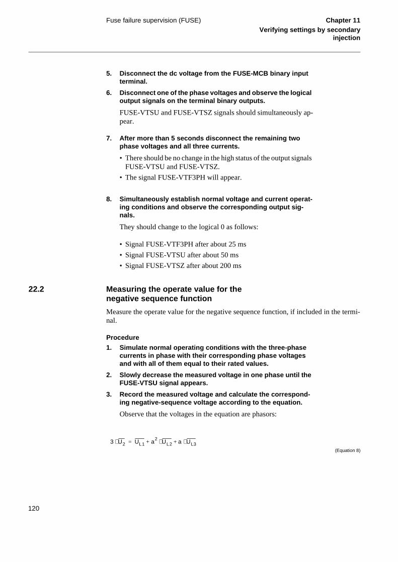
Fuse failure supervision (FUSE) Chapter 11Verifying settings by secondary
injection
termi-
5. Disconnect the dc voltage from the FUSE-MCB binary input terminal.
6. Disconnect one of the phase voltages and observe the logical output signals on the terminal binary outputs.
FUSE-VTSU and FUSE-VTSZ signals should simultaneously ap-pear.
7. After more than 5 seconds disconnect the remaining two phase voltages and all three currents.
• There should be no change in the high status of the output signals FUSE-VTSU and FUSE-VTSZ.
• The signal FUSE-VTF3PH will appear.
8. Simultaneously establish normal voltage and current operat-ing conditions and observe the corresponding output sig-nals.
They should change to the logical 0 as follows:
• Signal FUSE-VTF3PH after about 25 ms
• Signal FUSE-VTSU after about 50 ms
• Signal FUSE-VTSZ after about 200 ms
22.2 Measuring the operate value for the negative sequence function
Measure the operate value for the negative sequence function, if included in the nal.
Procedure
1. Simulate normal operating conditions with the three-phase currents in phase with their corresponding phase voltages and with all of them equal to their rated values.
2. Slowly decrease the measured voltage in one phase until the FUSE-VTSU signal appears.
3. Record the measured voltage and calculate the correspond-ing negative-sequence voltage according to the equation.
Observe that the voltages in the equation are phasors:
(Equation 8)
3 U2⋅ UL1 a2 UL2 a+⋅ UL3⋅+=
120

Fuse failure supervision (FUSE) Chapter 11Verifying settings by secondary
injection
4. Compare the result with the set value (consider that the set value 3U2> is in percentage of the base voltage U1b) of the negative-sequence operating voltage.
22.3 Measuring the operate value for the zero sequence function
Measure the operate value for the zero sequence function, if included in the terminal.
Procedure
1. Simulate normal operating conditions with the three-phase currents in phase with their corresponding phase voltages and with all of them equal to their rated values.
2. Slowly decrease the measured voltage in one phase until the FUSE-VTSU signal appears.
3. Record the measured voltage and calculate the correspond-ing zero-sequence voltage according to the equation.
Observe that the voltages in the equation are phasors.
(Equation 9)
4. Compare the result with the set value (consider that the set value 3U0> is in percentage of the base voltage U1b) of the zero-sequence operating voltage.
Where:
= the measured phase voltagesUL1 UL2 and UL3
a 1 ej 2 π⋅
3-----------
⋅ 0 5 j3
2-------+,–= =
Where:
= the measured phase voltages.
3 U0⋅ UL1 UL2 UL3+ +=
UL1 , UL2 and UL3
121

Fuse failure supervision (FUSE) Chapter 11Verifying settings by secondary
injection
22.4 Checking the operation of the du/dt, di/dt based function
Check the operation of the du/dt, di/dt based function, if included in the terminal.
Procedure
1. Simulate normal operating conditions with the three-phase currents in phase with their corresponding phase voltages and with all of them equal to their rated values.
2. Connect the nominal dc voltage to the FUSE-CBCLOSED bi-nary input.
3. Change the voltages and currents in all three phases simul-tanously.
The voltage change should be greater then set DU> and the current change should be less than the set DI<.
• The FUSE-VTSU and FUSE-VTSZ signals appear without any time delay. If the remaining voltage levels are higher than the set U< of the DLD function, only a pulse is achieved.
• FUSE-VTF3PH should appear after 5 seconds, if the remaining voltage levels are lower than the set U< of the DLD function.
4. Apply normal conditions as in step 1.
The FUSE-VTSU, FUSE-VTSZ and FUSE-VTF3PH signals should reset, if activated. See step 3.
5. Change the voltages and currents in all three phases simul-tanously.
The voltage change should be greater then set DU> and the current change should be greater then the set DI<.
The FUSE-VTSU, FUSE-VTSZ and FUSE-VTF3PH signals should not appear.
6. Disconnect the dc voltage to the FUSE-CBCLOSED binary in-put.
7. Apply normal conditions as in step 1.
8. Repeat step 3.
9. Connect the nominal voltages in all three phases and feed a current below the operate level in all three phases.
122

Fuse failure supervision (FUSE) Chapter 11Verifying settings by secondary
injection
10. Keep the current constant. Disconnect the voltage in all three phases simultaneously.
The FUSE-VTSU, FUSE-VTSZ and FUSE-VTF3PH signals should not appear.
22.5 Completing the test
Continue to test another function or complete the test by setting the test mode to off.
123

High speed binary output logic (HSBO) Chapter 11Verifying settings by secondary
injection
or
S---, set
h the
e to ived
23 High speed binary output logic (HSBO)
Prepare the terminal for verification of settings as outlined in section “Preparing ftest” in this chapter.
Since the high-speed binary out logic is dependent upon other function blocks (HZM1-, ZC1P-, ZCOM- and TRIP-) in order to operate, those functions have to beinto operating mode (On).
23.1 HSBO- trip from communication logic
Whenever a trip appears during these tests, it should be possible to block it througfunction input HSBO-BLKZCTR. Activation of either HSBO-BLKHSTR or HSBO-BLKHSCS should not block the trip outputs in this case. It should also be possiblblock the trip signals at the backing function from which the internal signals are der(ZC1P, ZCOM or TRIP).
Test for three of the trip schemes in ZC1P (Blocking Scheme not included).
Procedure
1. Apply inputs in different combinations to ZC1P-CACCLn, ZC1P-CRLm / ZC1P-CRMPH and check the outputs of HSBO-TRLx. For each trip, test the blocking action for all three HSBO blocking inputs and ZC1P-BLOCK.Check results ac-cording to the used scheme.
ZC1P/SchemeType = Intertrip
No local trip condition is required (-CACCLn). Trip output HSBO-TRLx will be activated directly according to corresponding -CRLx. Activation of -CRMPH should result in a three-phase trip.
ZC1P/SchemeType = PermissiveUR
When -CACCLn is applied in the same time as -CRLn (same phas-es), a trip output should appear in the n-phase(s), HSBO-TRLn. If -CRMPH is applied instead of -CRLn, a trip should appear in the same phase as -CACCLn.
Note!
No carrier send should appear during the tests in this section.
124

High speed binary output logic (HSBO) Chapter 11Verifying settings by secondary
injection
ZC1P/SchemeType = PermissiveOR
Same result as for the permissive underreach test should be ob-tained.
2. Remove applied signals.
Test for three of the trip schemes in ZCOM (Blocking Scheme not included) together with TRIP.
Procedure
1. Apply inputs in different combinations to TRIP-PSLn, ZCOM-CACC and ZCOM-CR and check the outputs of HSBO-TRLx. For each trip test the blocking action for all three HSBO block-ing inputs, ZCOM-BLOCK and TRIP-BLOCK. Check results according to the used scheme and trip program.
• ZCOM/SchemeType = Intertrip
• TRIP/Program = 1/2/3ph
When -PSLn is applied in the same time as -CR, a trip output should appear in the n-phase(s), HSBO-TRLn.
• ZCOM/SchemeType = PermissiveUR
• TRIP/Program = 1/3ph
When -PSLn is applied in the same time as -CACC and -CR, a trip output should appear in the n-phase(s), HSBO-TRLn.
• ZCOM/SchemeType = PermissiveOR
• TRIP/Program = 3ph
Each time -CACC and -CR are activated at the same time, a three-phase trip should be obtained, independent of any phase selection (-PSLn).
2. Remove applied signals.
125

High speed binary output logic (HSBO) Chapter 11Verifying settings by secondary
injection
ually e
ctiva-
23.2 HSBO- trip from the high-speed function (HS)
In order to test the performance of the high-speed binary out function alone without any interference from other functions the binary outputs configured for the HSBO function must not carry any other signals. For example, if the outputs are shared with the TRIP function the TRIP function should be switched off. In addition, the ZM1 function should be switched off in order to avoid unwanted intervention.
Whenever a trip or carrier send appears during these tests, it should be possible to block them through the function inputs HSBO-BLKHSTR and HSBO-BLKHSCS respective-ly.
Activation of HSBO-BLKZCTR should not block any outputs in this case since it does not belong to the high-speed function.
It should also be possible to block the output signals at the backing function from which the internal signals are derived (HS--).
High-speed trips will also be initiated by the HS--- function block.
Use the 3-phase test set to achieve the specified conditions.
Suggested fault characteristics, for all types of faults:
• Fault current at least 2 times Ir
• Prefault conditions: Uphase = 63.5 V, 0ë I = 0.0 A, 0ë• Fault conditions: Within set operating characteristic of HS function
During these tests the output will appear only for a short period of time (20ms), usthese pulses will be observable when connected to some indication device, but thblocking procedure has to be performed with the blocking input set before each ation of the function.
Procedure
1. Apply inputs in different combinations to ZC1P-CACCLn, ZC1P-CRLm / ZC1P-CRMPH and check the outputs of HSBO-TRL
When faults are applied according to Table 15, trip and carrier send outputs should appear as indicated (with YES)
126

High speed binary output logic (HSBO) Chapter 11Verifying settings by secondary
injection
Table 15: Output signals for different fault types
2. Remove applied signals.
3. Set the terminal in normal service.
23.3 HSBO- trip from the distance protection zone 1 function (ZM1)
In order to test the performance of the high-speed binary out function alone without any interference from other functions the binary outputs configured for the HSBO function must not carry any other signals. For example, if the outputs are shared with the TRIP function the TRIP function should be switched off.
Switch the HS function off as well.
Whenever a trip appears during these tests, it should be possible to block it through the function input HSBO-BLKHSTR.
Note that no carrier send will be issued from the distance protection function zone 1. Activation of HSBO-BLKZCTR or HSBO-BLKHSCS should not block any outputs in this test.
Use the 3-phase test set to achieve the specified conditions.
Suggested fault characteristics, for all types of faults:
• Prefault conditions: Uphase = 63.5 V, 0° I = 0.0 A, 0ë• Fault conditions: Within set operating characteristic of ZM1 function.
Fault type
Signal L1 L2 L3 L1,L2 L2,L3 L3,L1 L1,L2,L3
HSBO-TRL1 YES YES YES YES
HSBO-TRL2 YES YES YES YES
HSBO-TRL3 YES YES YES YES
HSBO-CSL1 YES YES YES YES
HSBO-CSL2 YES YES YES YES
HSBO-CSL3 YES YES YES YES
HSBO-CSMPH YES YES YES YES
127

High speed binary output logic (HSBO) Chapter 11Verifying settings by secondary
injection
Procedure
1. Apply faults according to table 16. Trip and carrier send out-puts should appear as indicated (with YES).
2. Remove applied signals.
3. Set the terminal in normal service.
Table 16: Output signals for different fault types
23.4 Completing the test
Continue to test another function or complete the test by setting the test mode to off.
Fault type
Signal L1 L2 L3 L1,L2 L2,L3 L3,L1 L1,L2,L3
HSBO-TRL1 YES YES YES YES
HSBO-TRL2 YES YES YES YES
HSBO-TRL3 YES YES YES YES
HSBO-CSL1
HSBO-CSL2
HSBO-CSL3
HSBO-CSMPH
128

Instantaneous overcurrent protection (IOC)
Chapter 11Verifying settings by secondary
injection
or
times
24 Instantaneous overcurrent protection (IOC)
Prepare the terminal for verification of settings as outlined in section “Preparing ftest” in this chapter.
To verify the settings the following fault type should be tested:
• One for a phase-to-earth fault
Ensure that the maximum continuous current of the terminal does not exceed fourits rated value.
24.1 Measuring the operate limit of set values
24.1.1 Phase overcurrent protection
Procedure
1. Inject a phase current in the terminal with start below the set-ting value.
2. Increase the injected current in the Ln phase until the IOC--TRLn (n=1-3) signal appears.
3. Switch off the fault current.
Observe the maximum permitted overloading of the current cir-cuits in the terminal.
4. Compare the measured operating current with the set value.
24.1.2 Residual overcurrent protection (non-dir.)
Procedure
1. Inject a phase current in the terminal with start below the set-ting value.
2. Increase the injected current in the Ln phase until the IOC--TRN signal appears.
3. Switch off the fault current.
Observe the maximum permitted overloading of the current cir-cuits in the terminal.
4. Compare the measured operating current with the set value.
129

Instantaneous overcurrent protection (IOC)
Chapter 11Verifying settings by secondary
injection
24.2 Completing the test
Continue to test another function or complete the test by setting the test mode to off.
130

Intercircuit bridging protection (TOVI) Chapter 11Verifying settings by secondary
injection
or tage
25 Intercircuit bridging protection (TOVI)
Prepare the terminal for verification of settings as outlined in section “Preparing ftest” in this chapter. For 16 2/3 Hz relays, use input (U1) and inject 50 Hz fault voland for 50 Hz relays, use input (U4) and inject 16 2/3 Hz fault voltage.
25.1 Measuring the operate and time limit of set values
Procedure
1. Check that the input logical signal TOVI--BLOCK is logical zero and note on the local HMI that the TOVI--TRIP logical sig-nal are equal to the logical 0.
Logical signals for intercircuit bridging protection are available under menu tree:
Service Report/Functions/IntCircBridge/FuncOutputs
2. Quickly set the measured voltage (fault voltage) to about 110% of the setting (U>, phase-neutral) operating voltage, and switch off the voltage with the switch.
3. Switch on the fault voltage and measure the operating time of the TOVI protection.
Use the TOVI--TRIP signal from the configured binary output to stop the timer.
4. Compare the measured time with the set value t.
5. Activate the TOVI--BLOCK binary input.
6. Switch on the fault voltage (110% of the setting) and wait longer than the set value t.
No TOVI--TRIP signal should appear.
7. Switch off the fault voltage.
8. Reset the TOVI--BLOCK binary input.
9. Quickly set the measured voltage (fault voltage) in same phase to about 90% of the setting (U>) operating voltage, and switch off the voltage with the switch.
10. Switch on the fault voltage and wait longer than the set value t.
No TOVI--TRIP signal should appear.
131

Intercircuit bridging protection (TOVI) Chapter 11Verifying settings by secondary
injection
11. Switch off the fault voltage.
12. Continue to test another function or complete the test by set-ting the test mode to off.
132

Local acceleration logic (ZCLC) Chapter 11Verifying settings by secondary
injection
or
ring
26 Local acceleration logic (ZCLC)
Prepare the terminal for verification of settings as outlined in section “Preparing ftest” in this chapter.
The logic is checked during the secondary injection test of the impedance measuzones.
Procedure
1. Supply the terminal with healthy conditions for at least two seconds.
2. Deactivate the conditions for accelerated function.
3. Apply a phase to earth fault at 100% of line impedance.
4. Check that the fault is tripped with the second zone time de-lay.
5. Supply the terminal with healthy conditions for at least two seconds.
6. Activate the condition for accelerated function either by the auto-recloser or by the loss of load.
7. Apply a phase to earth fault at 100% of line impedance.
8. Check that the fault is tripped “instantaneously”.
9. Continue to test another function or complete the test by set-ting the test mode to off.
133

Loss of voltage check (LOV) Chapter 11Verifying settings by secondary
injection
or
27 Loss of voltage check (LOV)
Prepare the terminal for verification of settings as outlined in section “Preparing ftest” in this chapter.
27.1 Measuring the operate limit of set values
Procedure
1. Check that the input logical signals LOV-BLOCK, LOV-BC and LOV-VTSU are logical zero.
2. Supply a three phase rated voltage in all three phases and note on the local HMI that the LOV-TRIP logical signal is equal to the logical 0.
Logical signals for loss of voltage check protection are available under menu tree:
ServiceReport/Functions/LossOfVoltage/FuncOutputs
3. Switch off the voltage in all three phases.
After seven seconds LOV-TRIP signal appears on the correspond-ing binary output or on the local HMI. Note that LOV--TRIP at this time is a pulse signal, duration should be about 150 ms.
4. Inject the measured voltages to their rated values for at least three seconds.
5. Activate the LOV-BC binary input.
6. Simultaneously disconnect all the three phase voltages from the terminal.
No LOV-TRIP signal should appear.
7. Inject the measured voltages to their rated values for at least three seconds.
8. Activate the LOV-VTSU binary input.
9. Simultaneously disconnect all the three phase voltages from the terminal.
No LOV-TRIP signal should appear.
10. Reset the LOV-VTSU binary input.
11. Inject the measured voltages to their rated values for at least three seconds.
134

Loss of voltage check (LOV) Chapter 11Verifying settings by secondary
injection
12. Activate the LOV-BLOCK binary input.
13. Simultaneously disconnect all the three phase voltages from the terminal.
No LOV-TRIP signal should appear.
14. Reset the LOV-BLOCK binary input.
15. Continue to test another function or complete the test by set-ting the test mode to off.
135

Monitoring of AC analogue measurements
Chapter 11Verifying settings by secondary
injection
or input
28 Monitoring of AC analogue measurements
Stabilized ac current and voltage generators and corresponding current, voltage, power and frequency meters with very high accuracy are necessary for testing the alternating quantity measuring function. The operating ranges of the generators must correspond to the rated alternate current and voltage of each terminal.
Prepare the terminal for verification of settings as outlined in section “Preparing ftest” in this chapter. Connect the generators and instruments to the correspondingterminals of a unit under test.
Procedure
1. Supply the terminal with voltages and currents.
Check that the values presented on the HMI unit correspond to the magnitude of input measured quantities within the limits of de-clared accuracy. The mean service values are available under the submenu:
Service Report/ServiceValues
The phasors of up to five input currents and voltages are available under the submenu:
Service Report/Phasors/Primary
2. Check the operation of ADBS or IDBS when applicable. Com-pare with the expected values.
The operation of ADBS or IDBS function can be checked sepa-rately with the RepInt = 0 setting. The value on the HMI follows the changes in the input measuring quantity continuously.
3. Check the set operate levels of the monitoring function by changing the magnitude of input quantities and observing the operation of the corresponding output relays.
The output contact changes its state when the changes in the input measuring quantity are higher than the set values HIWARN, HI-ALARM, or lower than the set values LOWWARN, LOW-ALARM.
4. Continue to test another function or complete the test by set-ting the test mode to off.
136

Monitoring of DC analogue measurements
Chapter 11Verifying settings by secondary
injection
or rrent
29 Monitoring of DC analogue measurements
A stabilized direct current generator and mA meter with very high accuracy for mea-surement of direct current is needed in order to test the dc measuring module. The gen-erator operating range and the measuring range of the mA meter must be at least between -25 and 25 mA.
Prepare the terminal for verification of settings as outlined in section “Preparing ftest” in this chapter. Connect the current generator and mA meter to the direct cuinput channels to be tested.
Procedure
1. Consider the need to block output signals.
2. Check that the values presented on the HMI module corre-sponds to the magnitude of input direct current within the lim-its of declared accuracy.
The service value is available under the submenu:
Service Report/I/O/Slotnm-MIMx/MIxy-Value
3. Check the operation of ADBS or IDBS function when applica-ble. Compare with the expected values.
The operation of ADBS or IDBS function can be checked sepa-rately with the setting of RepInt = 0. The value on the HMI must change only when the changes in input current (compared to the present value) are higher than the set value for the selected dead band.
where:
nm represents the serial number of a slot with tested mA input module
x represents the serial number of a mA input module in a terminal
y represents the serial number of a measuring channel on module x.
137

Monitoring of DC analogue measurements
Chapter 11Verifying settings by secondary
injection
4. Check the operating monitoring levels by changing the mag-nitude of input current and observing the operation of the cor-responding output relays.
The output contact changes its state when the changes in the input measuring quantity are higher than the set values RMAXAL, HI-WARN, HIALARM, or lower than the set values LOWWARN, LOWALARM, RMINAL.
5. Continue to test another function or complete the test by set-ting the test mode to off.
138

Multiple command (CM) Chapter 11Verifying settings by secondary
injection
30 Multiple command (CM)
Test of the multiple command function block is recommended to be performed in a sys-tem, that is, either in a complete delivery system as an acceptance test (FAT/SAT) or as parts of that system, because the command function blocks are connected in a delivery-specific way between bays and the station level.
Command function blocks included in the operation of different built-in functions must be tested at the same time as their corresponding functions.
139

Overload supervision (OVLD) Chapter 11Verifying settings by secondary
injection
or
31 Overload supervision (OVLD)
Prepare the terminal for verification of settings as outlined in section “Preparing ftest” in this chapter.
31.1 Measuring the operate and time limit of set values
Procedure
1. Check that the input logical signals OVLD-BLOCK is logical zero and note on the local HMI that the OVLD-TRIP logical sig-nal is equal to the logical 0.
Logical signals for overload supervision protection are available under menu tree:
ServiceReport/Functions/OverLoad/FuncOutputs
2. Quickly set the measured current (fault current) in all three phases to about 110% of the setting operating current, and switch off the current with the switch.
Observe the maximum permitted overloading of the current cir-cuits in the terminal.
3. Switch on the fault current and measure the operating time of the OVLD protection.
Use the OVLD-TRIP signal from the configured binary output to stop the timer.
4. Compare the measured time with the set value t.
5. Activate the OVLD-BLOCK binary input.
6. Switch on the fault current (110% of setting) and wait longer than the set value t.
No OVLD-TRIP signal should appear.
7. Switch off the fault current.
8. Reset the OVLD-BLOCK binary input.
9. Quickly set the measured current (fault current) in all three phases to about 90% of the measured operating current, and switch off the current with the switch.
140

Overload supervision (OVLD) Chapter 11Verifying settings by secondary
injection
10. Switch on the fault current and wait longer than the set value t.
No OVLD--TRIP signal should appear.
11. Switch off the fault current.
12. Continue to test another function or complete the test by set-ting the test mode to off.
141

Phase selection logic (PHS) Chapter 11Verifying settings by secondary
injection
or
e mea-rotec-
ea-higher
times nstant
ld be
32 Phase selection logic (PHS)
Prepare the terminal for verification of settings as outlined in section “Preparing ftest” in this chapter.
The phase selectors operate on the same measuring principles as the impedancsuring zones. So it is necessary to follow the same principles as for distance the ption, when performing the secondary injection tests.
Measure operating characteristics during constant current conditions. Keep the msured current as close as possible to its rated value or lower. But ensure that it is than 30% of the rated current.
Ensure that the maximum continuous current of a terminal does not exceed four its rated value, if the measurement of the operating characteristics runs under covoltage conditions.
To verify the settings the operating points according to figures 21, 22, and 23 shoutested. See also table 17 for information.
Figure 21: Operate characteristic for phase selection element, forward direction
en01000063.vsd
R
jX
ArgDir
P2
P1
ArgN
egRes
142

Phase selection logic (PHS) Chapter 11Verifying settings by secondary
injection
Figure 22: Phase selection characteristic for ph-ph faults
Figure 23: Phase selection characteristic for three-phase faults
en01000064.vsd
jX
70°
RArgDir
P2
P1
ArgN
egRes
en01000065.vsd
R
jX
100°
30°
P1
P2
143

Phase selection logic (PHS) Chapter 11Verifying settings by secondary
injection
Table 17: Test points
32.1 Measuring the operate limit of set values
Procedure
1. Supply the terminal with healthy conditions for at least two seconds.
2. Apply the fault condition and slowly decrease the measured impedance to find the operate value for of the phase to earth loop, test point P1, according to figure 21. Compare the result of the measurement with the expected value according to ta-ble 17.
The corresponding binary signals that inform about the operation of the phase-selection measuring elements are available in the lo-cal HMI under the menu:
Service Report/Functions/PhaseSelection
3. Repeat steps 1 to 2 to find the operate values for the remain-ing test points according to figures 21, 22 and 23 and to table 17.
4. Continue to test another function or complete the test by set-ting the test mode to off.
Phase-to-earth L3-E (Ω/Loop) Phase-to-phase loops L1-L2 (Ω/Loop)
Three-phase (Ω/Loop)
P1X = 0
P1R = RFPE
P1X = 0
P1R= RFPP
P1X = 0
P1R =1.1 · RFPP
P2R = 0
P2X = 2 · X1PP
P2R = 0
P2X = 2.67 · X1PP
P2R = 0P2X13--- 2 X1PE⋅ X0PE+( )⋅=
144

Pole discordance protection (PD) Chapter 11Verifying settings by secondary
injection
or
33 Pole discordance protection (PD)
Prepare the terminal for verification of settings as outlined in section “Preparing ftest” in this chapter.
Procedure
1. Activate the PD---POLDISC binary input, and measure the op-erating time of the PD protection.
Use the PD---TRIP signal from the configured binary output to stop the timer.
2. Compare the measured time with the set value t.
3. Reset the PD---POLDISC binary input.
4. Activate the PD---1POPEN binary input.
(This test should be performed together with AR).
5. Activate the PD---POLDISC binary input.
No PD---TRIP signal should appear.
6. Reset both PD---1POPEN and PD---POLDISC binary inputs.
7. Activate the PD---BLOCK binary input.
8. Activate the PD---POLDISC binary input.
No PD---TRIP signal should appear.
9. Reset both PD---BLOCK and PD---POLDISC binary inputs.
10. Continue to test another function or complete the test by set-ting the test mode to off.
145

Pole slip protection (PSP) Chapter 11Verifying settings by secondary
injection
or
es:
to fig-tic ecial
34 Pole slip protection (PSP)
Prepare the terminal for verification of settings as outlined in section “Preparing ftest” in this chapter.
The oscillation detection function in PSP operates in two different operating mod
• “One of three” phase operating mode
• “Two of three” phase operating mode
34.1 Measuring the operating characteristics
Testing instructions for measurement of the operation characteristics are related ure 24. Apply to the terminal the desired reach setting. The operating characterisshould be tested by applying the three phase faults in different points, to avoid sptesting for the one of three and two of three operating modes.
34.1.1 Applying additional settings
Apply the following additional settings on the terminal
• TrFwRv = On
• TrIncFwRv = On
• TrOutFwRv = Off
• TrFastFwRv = On
• TrDelFwRv = Off
• nFastFwRv = 0
• nDelFwRv = 10
• TrRvFw = On
• TrIncRvFw = On
• TrOutRvFw = Off
• TrFastRvFw = On
• TrDelRvFw = Off
• nFastRvFw = 0
• nDelRvFw = 10
34.1.2 Measuring the impedance boundaries
1. Set the measured impedance in the first quadrant to XM = 0 (measured reactance) and measured resistance (absolute val-ue) to
146

Pole slip protection (PSP) Chapter 11Verifying settings by secondary
injection
(Equation 10)
2. Decrease slowly (the transition from R1REXT to R1RINT must take longer time then the time set on the tP1 timer) the resis-tance and observe on local HMI the corresponding operating signals as follows:
PSP--ZOUT appears when
(Equation 11)
PSP--ZIN appears when
(Equation 12)
PSP--TRIP appears when
(Equation 13)
RM 1.2 R1REXT⋅=
0.95 R1REXT⋅ R M 1.05 R 1R EXT⋅≤ ≤
0.95 R1RINT⋅ RM 1.05 R1RINT⋅≤ ≤
0.95 R1RTR⋅ RM 1.05 R1RTR⋅≤ ≤
147

Pole slip protection (PSP) Chapter 11Verifying settings by secondary
injection
Figure 24: Operating characteristics with suggested testing points.
3. Set the measured impedance in the third quadrant to XM = 0 (measured reactance) and measured resistance (absolute val-ue) to
(Equation 14)
4. Decrease slowly the resistance and observe on local HMI the corresponding operating signals as follows:
PSP--ZOUT appears when
R
jX ZSB
ZL
ZSA
99001036.vsd
SCA
R1REXT
R1RINT
R1RTR
R1LEXT
R1LINT
R1LTR
X1FEXTX1FINT
X1PSLFWR1PSLFW
X1PSLRVR1PSLRV
Z1REXT
RM 1.2 R1LEXT⋅=
148

Pole slip protection (PSP) Chapter 11Verifying settings by secondary
injection
(Equation 15)
PSP--ZIN appears when
(Equation 16)
PSP--TRIP appears when
(Equation 17)
5. Set the measured impedance in the first quadrant to RM = 0 (measured resistance) and measured reactance to:
(Equation 18)
6. Decrease slowly the reactance and observe on local HMI the corresponding operating signals as follows:
PSP--ZOUT appears when
(Equation 19)
PSP--ZIN appears when
(Equation 20)
7. Set the measured impedance in the third quadrant to RM = 0 (measured resistance) and measured reactance (absolute val-ue) to:
0.95 R1LEXT⋅ RM 1.05 R1LEXT⋅≤ ≤
0.95 R1LINT⋅ RM 1.05 R1LINT⋅≤ ≤
0.95 R1LTR⋅ RM 1.05 R1LTR⋅≤ ≤
XM 1.2 X1 FEXT⋅=
0.95 X1FEXT⋅ XM 1.05 X1FEXT⋅≤ ≤
0.95 X1FINT⋅ XM 1.05 X1 FINT⋅≤ ≤
149

Pole slip protection (PSP) Chapter 11Verifying settings by secondary
injection
(Equation 21)
8. Decrease slowly the reactance and observe on local HMI the corresponding operating signals as follows:
PSP--ZOUT appears when
(Equation 22)
PSP--ZIN appears when
(Equation 23)
9. Set the measured impedance in the third quadrant to
(Equation 24)
and
(Equation 25)
10. Decrease slowly the measured reactance until the signal PSP--TRIP appears on the local HMI.
The recorded operating value should be in the following limits:
(Equation 26)
11. Set the measured impedance in the first quadrant to
(Equation 27)
XM 1.2 X1 FEXT⋅=
0.95 X1RE XT⋅ XM 1.05 X1REXT⋅≤ ≤
0.95 X1RINT⋅ XM 1.05 X1RINT⋅≤ ≤
RM R1PSLRV–=
XM 1.2 X1PSLRV–( )⋅=
0.95 X1PSLRV⋅ XM 1.05 X1PSLRV⋅≤ ≤
RM R1PSLRV=
150

Pole slip protection (PSP) Chapter 11Verifying settings by secondary
injection
and
(Equation 28)
12. Decrease slowly the measured absolute value of the reac-tance until the signal PSP--TRIP appears on the local HMI.
The recorded operating value should be in the following limits:
(Equation 29)
13. Set the measured impedance in the first quadrant to
(Equation 30)
and
(Equation 31)
14. Decrease slowly the measured resistance until the signal PSP--ZOUT appears on the local HMI. Check that the mea-sured value and the calculated angle correspond to the con-dition:
(Equation 32)
Parameter R1REXTM is a recorded value of the measured resis-tance when measuring the operating resistance for the R1REXT operating characteristic.
15. Check the correct operation of the “two of three” phase oper-ating mode.
XM 1.2 X 1P SLRV⋅=
0.95 X1PSLFW⋅ XM 1.05 X1PSLFW⋅≤ ≤
RM 1.2 R1R EXT⋅=
XM 0.5 X1FEXT⋅=
SCA 5O–
0.5 X1FEXT⋅RM R1REXTM–---------------------------------------------
atan SCA 5O+≤ ≤
151

Pole slip protection (PSP) Chapter 11Verifying settings by secondary
injection
tran-stem n par-
quip-e set-ents
4) in hen ire-
16. Apply the single phase fault and repeat the measurement of the operating value for the R1RTR.
The PSP--TRIP signal must not appear when the measured resis-tance is decreased under the previous measured operating value.
17. Observe on local HMI also the PSP--START functional output signal.
It should be active always when the slowly decrease impedance enters the inner oscillation detection boundary.
18. Apply the required settings for the operating parameters, which have been changed for the purposes of the measure-ment item 34.1.1.
34.2 Testing the pole slip functionality
Programmable testing equipment is required for testing of the complete functionality. Two possible ways of testing are applicable:
• It is possible to replay by the testing equipment some of the most characteristicsients, which have been recorded by digital disturbance recorders during the systudy stage. This way it is necessary to observe the responses of the function oticular recorded transients and compare them with the required response.
• It is possible to program the sequence of the measuring points in the testing ement and their repetition rate. The programs should be prepared according to thtings applied and the required functionality of the PSP function. Figure 20 prestwo typical examples of the required operating points to be programmed.
The first programmed sequence (clockwise) includes two operating points (3 andthe fast tripping area. The sequence is applicable for testing of the functionality, wthe FwRv oscillations should cause the tripping action. The following special requments should be observed:
152

Pole slip protection (PSP) Chapter 11Verifying settings by secondary
injection
point s the
ing rating astF-
ing rating astF-
he os-uired oint et on
• The measured impedance should remain for the first sequence in the operating2 longer than the time set on the initial timer tP1. For the consecutive sequencetime should be longer than the one set on the tP2 timer.
• The PSP protection should issue the PSP--TRIP signal, if it is set for the incomtrip in the fast tripping region, when the measured impedance reaches the opepoint 3. It is necessary to observe that the sequence must be completed for nFwRv times.
• The PSP protection should issue the PSP--TRIP signal, if it is set for the outgotrip in the fast tripping region, when the measured impedance reaches the opepoint 4. It is necessary to observe that the sequence must be completed for nFwRv times.
• The programmed sequence must reach also the measuring points 5 and 6, if tcillation is supposed to be completed and a higher number of oscillations is reqfor the final trip command. Observe also, that the time required to move from p5 over the points 6, 7, 8, and 1 to point 2 again must be shorter then the time sthe tW timer.
153

Pole slip protection (PSP) Chapter 11Verifying settings by secondary
injection
s. No ed ac-
Figure 25: Two examples of programmed impedance measuring points for functional testing of the pole slip protection.
The second programmed sequence (anti-clockwise) on figure 25 presents a RvFw tran-sition with operating points 3 and 4 in delayed tripping area. The sequence is applicable for testing of the functionality, when the RvFw oscillations should cause the tripping action. The following special requirements should be observed as for the first operating sequence.
34.3 Testing the additional functionality
All additional functionality, as described in this document, should be tested only, when used in actual application. The functionality should be tested by the so called "go - no go” tests according to the expected operation under the certain system conditionspecial instructions can be given for such tests. The instructions should be preparcording to the requirements of the actual application.
R
jX
ZL
ZSA
99001037.vsd
1234
56
7 8
ZSB
1 2 3
45
6
87
154

Pole slip protection (PSP) Chapter 11Verifying settings by secondary
injection
34.4 Completing the test
Continue to test another function or complete the test by setting the test mode to off.
155
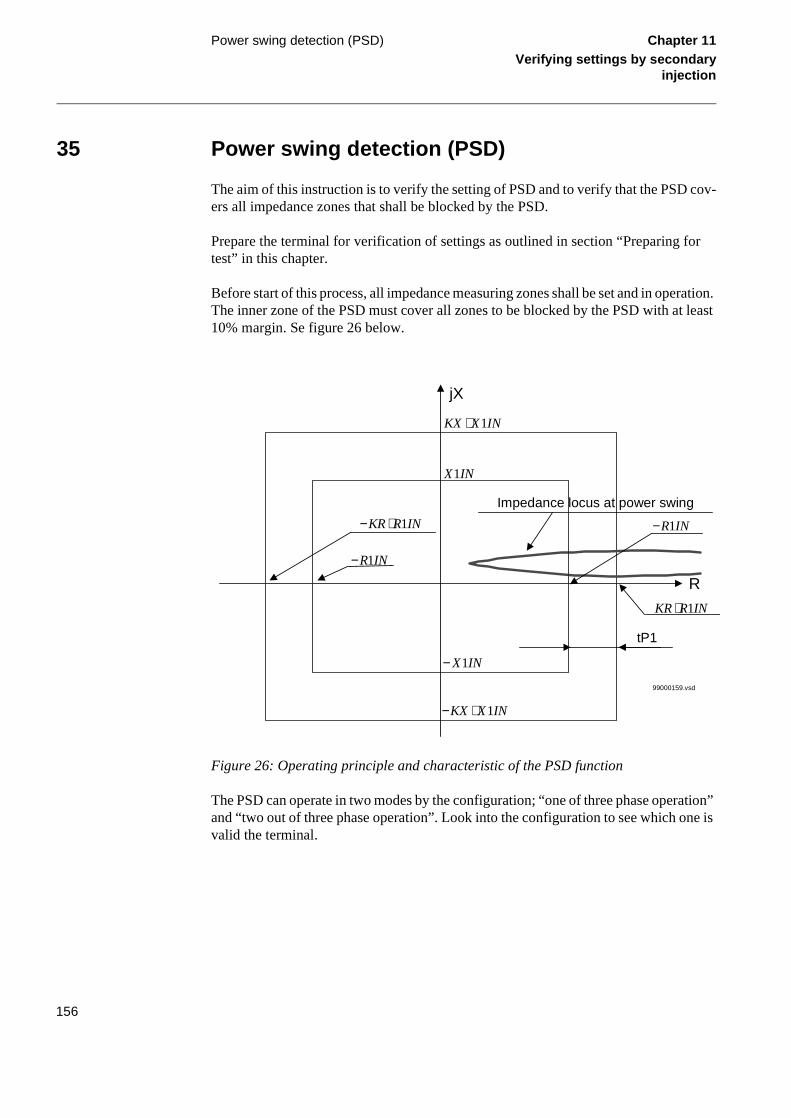
Power swing detection (PSD) Chapter 11Verifying settings by secondary
injection
or
ration. least
ation” e is
35 Power swing detection (PSD)
The aim of this instruction is to verify the setting of PSD and to verify that the PSD cov-ers all impedance zones that shall be blocked by the PSD.
Prepare the terminal for verification of settings as outlined in section “Preparing ftest” in this chapter.
Before start of this process, all impedance measuring zones shall be set and in opeThe inner zone of the PSD must cover all zones to be blocked by the PSD with at10% margin. Se figure 26 below.
Figure 26: Operating principle and characteristic of the PSD function
The PSD can operate in two modes by the configuration; “one of three phase operand “two out of three phase operation”. Look into the configuration to see which onvalid the terminal.
jX
R
tP1
Impedance locus at power swing
99000159.vsd
− ⋅KX X IN1
− X IN1
X IN1
KX X IN⋅ 1
− ⋅KR R IN1
KR R IN⋅ 1
−R IN1
−R IN1
156

Power swing detection (PSD) Chapter 11Verifying settings by secondary
injection
35.1 Testing overview
1. Re-configure the binary output from the PSD--ZOUT signal to the PSD--START signal of the PSD function.
It is also possible to observe the PSD--START signal on the regu-lar output terminals, if provided during the engineering stage. Check the corresponding terminal documentation.
2. Decrease slowly the measured voltages in all three phases until the W-meter detects the appearance of the PSD--START signal.
3. Increase the measured voltages to their rated values.
4. Decrease instantaneously voltages in all three phases to the values, which are for approximately 20% lower than the set value R1IN.
The START signal must not appear.
5. Increase the measured voltages to their rated values.
35.2 Testing the one-of-three-phase operation
1. Check the existing (default) configuration of the following function input signals:
PSD--REL1PH, PSD--BLK1PH, PSD--REL2PH, PSD--BLK2PH and record the connections.
2. Reconfigure the terminal according to the following list:
• PSD--REL1PH to FIXD-ON
• PSD--BLK1PH to FIXD-OFF
• PSD--REL2PH to FIXD-OFF
• PSD--BLK2PH to FIXD-ON
3. Disconnect the L2 and L3 currents from the terminal and check that they are short-circuited on the output terminal of the testing equipment.
4. Decrease slowly the measured voltages until the PSD--START signal appears.
5. Increase the measured voltages to their rated values.
35.3 Testing the two-of-three-phase operation
1. Reconfigure the terminal according to the following list:
157

Power swing detection (PSD) Chapter 11Verifying settings by secondary
injection
• PSD--REL1PH to FIXD-OFF
• PSD--BLK1PH to FIXD-ON
• PSD--REL2PH to FIXD-ON
• PSD--BLK2PH to FIXD-OFF
2. Decrease slowly the measured voltages to the value, which is for approximately 20% lower than the operation value for the R1IN measuring point.
No PSD--START signal must appear.
3. Increase the measured voltages to their rated values.
4. Connect the phase L2 current to the terminal again.
5. Decrease the measured voltages until the PSD--START signal appears.
6. Increase the measured voltages to their rated values.
7. Connect the phase L3 current to the terminal.
8. Return the original configuration for the functional inputs PSD--REL1PH, PSD--BLK1PH, PSD--REL2PH, and PSD--BLK2PH.
35.4 Testing the tEF timer and functionality
1. Check and record the default configuration for the PSD--TR-SP, PSD--I0CHECK, PSD--BLKI01, PSD--BLKI02, and PSD--BLOCK functional inputs.
2. Re-configure the functional inputs PSD--TRSP and PSD--I0CHECK to two empty binary inputs of a terminal.
3. Configure functional inputs PSD--BLKI01, and PSD--BLKI02 to the FIXD-ON functional output and the PSD--BLOCK func-tional input to the FIXD-OFF functional input.
4. Connect the binary input towards the PSD--I0CHECK func-tional input via an open switch to the constant positive dc voltage.
5. Connect the binary input towards the PSD--TRSP functional input via a closed switch to the constant positive dc voltage.
6. Decrease the measured voltages slowly until the START sig-nal appears.
7. Close the switch towards the binary input with PSD--I0CHECK connection and observe the PSD--START signal.
It must reset instantaneously.
158

Power swing detection (PSD) Chapter 11Verifying settings by secondary
injection
8. Open the switch towards the PSD--I0CHECK functional input.
9. Open the switch towards the PSD--TRSP functional input and close with some time delay the switch towards the PSD--I0CHECK functional input.
The PSD--START signal resets, if the time difference between opening the first and closing the second switch is shorter than the time delay set on the tEF timer. The PSD--START signal does not reset in the opposite case.
10. Increase the measured voltages to their rated values.
35.5 Testing the tR1 timer
1. Disconnect the dc voltage from the binary inputs connected to the PSD--TRSP and PSD--I0CHECK functional inputs.
2. Connect the binary input towards the PSD--I0CHECK func-tional input via an open switch to the constant positive dc voltage.
3. Re-configure the PSD--BLKI02 functional input to the FIXD-OFF functional output.
4. Decrease the measured voltages slowly until the PSD--START signal appears.
5. Close the switch towards the PSD--I0CHECK binary input and observe the PSD--START signal.
It must reset with the time delay set on the tR1 timer. It is also pos-sible to measure this time delay with timer, which starts with clos-ing of a switch and stops with the reset of a PSD--START signal on the corresponding binary output.
6. Increase the measured voltages to their rated values.
35.6 Testing the tR2 timer
1. Disconnect the dc voltage from the binary input connected to the PSD--I0CHECK functional input.
2. Re-configure the functional input PSD--BLKI02 to the FIXD-ON functional input and PSD--BLKI01 to the FIXD-OFF func-tional output.
3. Decrease slowly the measured voltages until the PSD--START signal appears.
It should reset after the time delay, set on tR2 timer. It is also pos-sible to measure the time delay tR2.
159

Power swing detection (PSD) Chapter 11Verifying settings by secondary
injection
4. Connect for this purpose the timer to the binary output with the PSD--START signal.
5. Start the timer with change of the signal from 0 to 1 and stop it with the change from 1 to 0.
6. Increase the measured voltages to their rated values
35.7 Testing the block input
1. Re-configure the functional input PSD--BLOCK to the binary input, to which the PSD--I0CHECK has been configured so far.
2. Re-configure the functional input PSD--BLKI01 to the FIXD-ON functional input.
3. Decrease slowly the measured voltages in all three phases until the PSD--START signal appears.
4. Close the switch towards the PSD--BLOCK binary input and observe the PSD--START signal.
It must reset instantaneously.
5. Increase the measured voltages to their rated values.
6. Re-configure the functional inputs PSD--TRSP, PSD--I0CHECK, PSD--BLKI01, PSD--BLKI02, and PSD--BLOCK to their original configuration.
35.8 Completing the test
Continue to test another function or complete the test by setting the test mode to off.
160

Power swing logic (PSL) Chapter 11Verifying settings by secondary
injection
or
f the lled the sting
ting
36 Power swing logic (PSL)
Prepare the terminal for verification of settings as outlined in section “Preparing ftest” in this chapter.
Most of the testing equipment available on the market does not permit simulation opower-swing conditions and simultaneous occurrence of different faults with controfault impedance. For this reason it is necessary to enable the logic by connectingPSL--STPSD input signal to some other functional signal, which is used for the tepurposes.
Make sure that the existing configuration permits monitoring of the PSL--CS, PSL--TRIP signals on the binary outputs of the terminal. If not, configure it for tespurposes to some, not used, binary outputs.
36.1 Testing the carrier send and trip signals
Procedure
1. Set the operation of all distance zones, which are supposed to be blocked by the operation of the PSD function, to Off.
2. Configure the PSL--STPSD functional inputs to the ZMn--TRIP of the underreaching power-swing zone, if the underreaching communication scheme is used.
3. Start instantaneously any kind of fault within the underreach-ing power-swing zone and check, that:
• The PSL--CS signal appears after the time delay, which is equal to the sum of set time delays for the underreaching zone tnPP or tnPE (dependent on the type of fault) and for the carrier send se-curity timer tCS. Also add the usual operate time for the under-reaching zone (approximately. 30ms).
• The PSL--TRIP signal appears after the time delay, which is equal to the sum of set time delays for the underreaching zone tnPP or tnPE (dependent on the type of fault) and for the trip se-curity timer tTrip. Also add the usual operate time for the under-reaching zone (approximately. 30ms).
4. Simulate the receiving of the carrier signal so that the func-tional input signal PSL--CR becomes a logical one.
5. Configure the PSL--STPSD input to the output ZMn--START of the carrier accelerating zone (Power-swing overreaching zone).
161

Power swing logic (PSL) Chapter 11Verifying settings by secondary
injection
idual by
6. Initiate any kind of fault within the carrier accelerating zone and check that the PSL--TRIP signal appears after the time, which is equal to the time delay set on the trip timer tTrip.
Also consider the (average) operate time of the carrier acceleration zone (approximately. 30ms).
36.2 Testing the influence of the residual overcurrent protection
Additionally connect the REx 5xx terminal according to the test instructions for the di-rectional O/C EF protection (see the section “Definite and inverse time-delayed resovercurrent protection (TEF)”), if the PSL is configured in a way, to be controlled this protection.
Procedure
1. Initiate a single-phase-to-earth fault within both power-swing zones.
Make sure that none of PSL--CS and PSL--TRIP output signals appear after the time delays tCS and tTrip.
The PSL--BLKZMPP must appear together with the fault and must remain active until the fault has been switched off plus the time delay, as set on the tBlkTr timer.
2. Initiate a Ph-Ph fault within the operating area of both power-swing zones.
Make sure that PSL--CS and PSL--TRIP output signals appear af-ter the time delays tCS.
3. Switch On the operation of the zone 1 distance protection function and fulfill all the conditions for single-pole auto-re-closing.
4. Simulate a single-phase-to-earth fault within the reach of zone 1 and both power-swing zones.
The fault should cause a single-pole tripping and should be switched off with the normal operating time of zone 1.
5. Repeat the fault within the dead-time of single-pole auto-re-closing.
Make sure, that the PSL function perform a PSL--BLKZMPP sig-nal and no PSL--CS and PSL--TRIP.
162

Power swing logic (PSL) Chapter 11Verifying settings by secondary
injection
36.3 Controlling of the underreaching zone
Procedure
1. Set the operation of all normal distance protection zones to On.
2. Simulate a fault without fault resistance in the middle of the distance protection zone 1.
Make sure that the trip appears within the operate time for the dis-tance protection zone 1 and no PSL--BLKZMH output signal ap-pears.
3. Switch Off the fault and prepare a new fault without fault re-sistance within the normal distance protection zone 2 operate area, but outside the zone 1 operate area.
4. Switch On the fault and move it into the zone 1 operate area with time delay longer than the time set on tDZ timer and fast-er than the time set on timer tZL.
5. Observe the operate time, which must be equal to the operate time of zone 1, after the measured impedance enters its oper-ate area.
No delayed operation of zone 1 must be observed.
6. Configure the PSL--STPSD functional input to the PSD--START functional output and repeat the previous fault.
Fast trip, caused by the operation of zone 1 must appear with a time delay, which is equal to the set time delay on the timer tZL plus zone 1 normal operate time. Also observe the PSL--BLKZMH functional output signal, which must appear for a short time.
7. Be sure to establish the original configuration of the terminal and the original settings of all setting parameters.
36.4 Completing the test
Continue to test another function or complete the test by setting the test mode to off.
163

Pulse counter logic (PC) Chapter 11Verifying settings by secondary
injection
37 Pulse counter logic (PC)
The test of the pulse counter function requires at least the PST Parameter Setting Tool or SPA (or LON) connection to a station HMI including corresponding functionality. A known number of pulses are with different frequency connected to the pulse counter in-put. The test should be performed for the settings operation = Off/On and for blocked/deblocked function. The pulse counter value is then read by the PST or station HMI.
164

Radial feeder protection (PAP) Chapter 11Verifying settings by secondary
injection
or
e-ure
unit
38 Radial feeder protection (PAP)
Prepare the terminal for verification of settings as outlined in section “Preparing ftest” in this chapter.
The PAP function operates in conjunction with the teleprotection scheme where rceived carrier signal (CR) is one condition for activating the function. This proceddoes not cover the necessary actions to test the teleprotection channel.
The corresponding binary signals informing the operator about the operation of theare available in the local HMI under the menu:
ServiceReport/Functions/RadialFeederP
38.1 Testing the fast fault clearance
Procedure
1. Simulate the fault conditions in one phase by suddenly lower-ing the voltage below 70% of the nominal value of the termi-nal.
At the same time simulate the reception of a Carrier Receive (CR) signal. The fast fault clearance shall take place. If the fault is sim-ulated on at least two phases the trip will be a three-phase trip.
38.2 Testing the delayed fault clearance
1. Disconnect the wire used for the CR signal.
2. Repeat the test according to step 1 in sub task 38.1 above.
Depending on selection mode, that is on the setting parameters Del1PhFltTrip, ResCurCheck, Del3PhTrip, the trip will be a sin-gle-phase or three-phase trip with or without residual current check. See the table below.
165

Radial feeder protection (PAP) Chapter 11Verifying settings by secondary
injection
38.3 Completing the test
Continue to test another function or complete the test by setting the test mode to off.
Parameter On Off
Del1PhFltTrip Single phase trip for single phase
fault in time tM
Three-phase trip for single-
phase fault in time tT
ResCurCheck Single-Phase trip with residual current check
Single-phase trip without residual current check
Del3PhTrip Time delayed trip for three-phase fault
No time delayed trip for three-phase fault
166

Setting lockout (HMI) Chapter 11Verifying settings by secondary
injection
39 Setting lockout (HMI)
1. Configure the HMI--BLOCKSET functional input to the binary input, which is determined by the engineering or the input that is not used by any other function.
2. Set the setting restriction to SettingRestrict = Block.
3. Connect rated DC voltage to the selected binary input.
4. Try to change the setting of any parameter for one of the func-tions.
Reading of the values must be possible.
The terminal must not respond to any attempt to change the setting value or configuration.
5. Disconnect the control DC voltage from the selected binary input.
6. Repeat the attempt under step 4.
The terminal must accept the changed setting value or configura-tion.
7. Depending on the requested design for a complete REx 5xx terminal, leave the function active or reconfigure the function into the default configuration and set the setting restriction function out of operation to SettingRestrict = Open.
8. Continue to test another function or complete the test by set-ting the test mode to off.
167

Scheme communication logic for distance protection functions (ZCOM)
Chapter 11Verifying settings by secondary
injection
or
suring ets for
in-ve a
ith
in-
40 Scheme communication logic for distance protection functions (ZCOM)
Prepare the terminal for verification of settings as outlined in section “Preparing ftest” in this chapter.
Check the scheme logic during the secondary injection test of the impedance-meazones and the high-speed complementary zones. For details see the ordering sheeach particular REx 5xx terminal.
Activating the different zones verifies that the ZCOM-CS signal is issued from thetended zones. The ZCOM-CS signal from the independent tripping zone must hatSendMin minimum time.
Check the tripping function by activating the ZCOM-CR and ZCOM-CRG inputs wthe overreaching zone used to achieve the ZCOM-CACC signal.
It is sufficient to activate the zones with only one type of fault with the secondary jection.
40.1 Testing permissive underreach
Procedure
1. Activate carrier receive (ZCOM-CR) signal of the terminal.
2. Supply the relay with healthy conditions for at least two sec-onds.
3. Apply a fault condition within the permissive zone.
4. Check that correct trip outputs, external signals, and indica-tion are obtained for the actual type of fault generated.
5. Check that other zones operate according to their zone timer and that the carrier send (ZCOM-CS) signal is obtained only for the zone configured to give the actual signal.
6. Deactivate the carrier receive (ZCOM-CR) signal of the termi-nal.
7. Check that the trip time complies with the zone timers and that correct trip outputs, external signals, and indication are obtained for the actual type of fault generated.
168

Scheme communication logic for distance protection functions (ZCOM)
Chapter 11Verifying settings by secondary
injection
40.2 Testing permissive overreach
Procedure
1. Activate the carrier receive (ZCOM-CR) signal of the terminal.
2. Supply the relay with healthy conditions for at least two sec-onds.
3. Apply a fault condition within the permissive zone.
4. Check that correct trip outputs, external signals, and indica-tion are obtained for the actual type of fault generated.
5. Check that the other zones operate according to their zone timer and that the carrier send (ZCOM-CS) signal is obtained only for the zones that are configured to give the actual sig-nal.
6. Deactivate the carrier receive (ZCOM-CR) signal of the termi-nal.
7. Supply the relay with healthy conditions for at least two sec-onds.
8. Apply a fault condition within the permissive zone.
9. Check that trip time complies with the zone timers and that correct trip outputs, external signals, and indication are ob-tained for the actual type of fault generated.
40.3 Testing blocking scheme
Procedure
1. Deactivate the carrier receive (ZCOM-CR) signal of the termi-nal.
2. Supply the relay with healthy conditions for at least two sec-onds.
3. Apply a fault condition within the forward directed zone used for scheme communication tripping.
4. Check that correct trip outputs and external signals are ob-tained for the type of fault generated and that the operate time complies with the tCoord timer (plus relay-measuring time).
5. Check that the other zones operate according to their zone times and that a carrier send (ZCOM-CS) signal is only ob-tained for the reverse zone.
6. Activate the carrier receive (ZCOM-CR) signal of the terminal.
7. Apply a fault condition in the forward directed zone used for scheme communication tripping.
169

Scheme communication logic for distance protection functions (ZCOM)
Chapter 11Verifying settings by secondary
injection
8. Check that the no trip from scheme communication occurs.
9. Check that trip time from the forward directed zone used for scheme communication tripping complies with the zone timer and that correct trip outputs, external signals, and indication are obtained for the actual type of fault generated.
40.4 Checking of unblocking logic
Check the unblocking function (if the function is required) when you check the com-munication scheme.
40.4.1 Command function with continuous unblocking (Unblock = 1).
Procedure
1. Activate the carrier guard input signal (ZCOM-CRG) of the ter-minal.
2. Using the scheme selected, check that a carrier accelerated trip (ZCOM-TRIP) is obtained when the carrier guard signal is deactivated.
40.5 Completing the test
Continue to test another function or complete the test by setting the test mode to off.
170

Scheme communication logic for residual overcurrent protection (EFC)
Chapter 11Verifying settings by secondary
injection
or nt rding
ded, f the
41 Scheme communication logic for residual overcurrent protection (EFC)
Prepare the terminal for verification of settings as outlined in section “Preparing ftest” in this chapter. Before testing the communication logic for residual overcurreprotection, the time delayed residual overcurrent protection has to be tested accoto the corresponding instruction. Then continue with the instructions below.
If the current reversal and weak-end-infeed logic for earth-fault protection is incluproceed with the testing according to the corresponding instruction after the test ocommunication logic for residual overcurrent protection. The reversal current andweak-end-infeed functions shall be tested together with the permissive scheme.
41.1 Testing the directional comparison logic function
41.1.1 Blocking scheme
Procedure
1. Inject the polarising voltage 3U0 to 5% of Ub and the phase angle between voltage and current to 65°, the current lagging the voltage.
2. Inject current (65° lagging the voltage) in one phase to about 110% of the setting operating current, and switch off the cur-rent with the switch.
3. Switch on the fault current and measure the operating time of the EFC logic.
Use the EFC--TRIP signal from the configured binary output to stop the timer.
4. Compare the measured time with the set value tCoord.
5. Activate the EFC--CR binary input.
6. Check that the EFC--CRL output is activated when EFC--CR input is activated.
7. Switch on the fault current (110% of the setting) and wait long-er than the set value tCoord.
No EFC--TRIP signal should appear.
8. Switch off the fault current.
9. Reset the EFC--CR binary input.
10. Activate the EFC--BLOCK digital input.
171

Scheme communication logic for residual overcurrent protection (EFC)
Chapter 11Verifying settings by secondary
injection
11. Switch on the fault current (110% of the setting) and wait long-er than the set value tCoord.
No EFC--TRIP signal should appear.
12. Switch off the fault current and the polarising voltage.
13. Reset the EFC--BLOCK digital input.
41.1.2 Permissive scheme
Procedure
1. Inject the polarising voltage 3U0 to 5% of Ub and the phase angle between voltage and current to 65°, the current lagging the voltage.
2. Inject current (65° lagging the voltage) in one phase to about 110% of the setting operating current, and switch off the cur-rent with the switch.
3. Switch on the fault current (110% of the setting) and wait long-er than the set value tCoord.
No EFC--TRIP signal should appear, and the EFC--CS binary out-put should be activated.
4. Switch off the fault current.
5. Activate the EFC--CR binary input.
6. Switch on the fault current (110% of the setting) and measure the operating time of the EFC logic.
Use the EFC--TRIP signal from the configured binary output to stop the timer.
7. Compare the measured time with the set value tCoord.
8. Activate the EFC--BLOCK digital input.
9. Switch on the fault current (110% of the setting) and wait long-er than the set value tCoord.
No EFC--TRIP signal should appear.
10. Switch off the fault current and the polarising voltage.
11. Reset the EFC--CR binary input and the EFC--BLOCK digital input.
41.2 Completing the test
Continue to test another function or complete the test by setting the test mode to off.
172

Sensitive directional residual overcurrent protection (WEF1)
Chapter 11Verifying settings by secondary
injection
or
tional U
rrent
42 Sensitive directional residual overcurrent protection (WEF1)
Prepare the terminal for verification of settings as outlined in section “Preparing ftest” in this chapter.
Figure 27 shows the connection of the test-set during the test of the sensitive direcresidual overcurrent protection. Observe that the polarizing voltage is equal to -30. The current inputs I5 are specially suited for the WEF1 function.
Figure 27:
Values of the logical signals belonging to the sensitive directional residual overcuprotection are available under menu tree:
Relay test set
NI
REx5xx
IN (I4 alt I5)
L1U
L2U
L3U
NU
U1
U2
U3
NU
TRIP
Alternatives
en01000093.vsd
-3U0U4
173

Sensitive directional residual overcurrent protection (WEF1)
Chapter 11Verifying settings by secondary
injection
ServiceReport/Functions/WEF1
42.1 Measuring the operate and time limit for set values
Procedure
1. Set the polarizing voltage to 1.2xUN> and the phase angle be-tween voltage and current to the set characteristic angle (RCA), the current lagging the voltage.
2. Measure that the operate current of the set directional ele-ment is equal to the INcosPhi> setting.
The I Dir (I0 cos(Angle)) function activates the WEF1-START and WEF1-STFW outputs at setting ‘Forward’ and WEF1-START and WEF1-STRV outputs at setting ‘Reverse’.
3. Measure with angles ϕ = Angle +/- 45° that the measuring ele-ment operates when I 0 cos (Angle - ϕ) =INcosPhi>.
4. Compare the result with the set value.
5. Measure the operate time of the timer by injecting a current two times the set I operate value and the polarizing voltage 1.2xUset.
6. Compare the results with the set value.
7. Decrease the polarizing voltage until WEF1-STU appears. Compare it with the set value.
8. Continue to test another function or complete the test by set-ting the test mode to off.
174

Sensitive directional residual power protection (WEF2)
Chapter 11Verifying settings by secondary
injection
or
tional U
rrent
43 Sensitive directional residual power protection (WEF2)
Prepare the terminal for verification of settings as outlined in section “Preparing ftest” in this chapter.
Figure 28 shows the connection of the test-set during the test of the sensitive direcresidual overcurrent protection. Observe that the polarizing voltage is equal to -30. The current inputs I5 are specially suited for the WEF2 function.
Figure 28:
Values of the logical signals belonging to the sensitive directional residual overcuprotection are available under menu tree:
Relay test set
NI
REx5xx
IN (I4 alt I5)
L1U
L2U
L3U
NU
U1
U2
U3
NU
TRIP
Alternatives
en01000093.vsd
-3U0U4
175

Sensitive directional residual power protection (WEF2)
Chapter 11Verifying settings by secondary
injection
ServiceReport/Functions/WEF2
43.1 Measuring the operate and time limit of set values
Procedure
1. Set the polarizing voltage to 1.2xUN> and the phase angle be-tween voltage and current to the set characteristic angle (RCA), the current lagging the voltage.
2. Measure that the operate power is equal to the Iset Uset cos(Angle) setting for the set directional element.
The function activates the WEF2-START output.
3. Measure with angles ϕ = Angle +/- 45° that the measuring ele-ment operates when I 0 U0 cos (Angle - ϕ) = Sset.
4. Compare the result with the set value.
5. Measure the operate time of the timer by injecting a current to get two times the set S operate value.
(Equation 33)
6. Compare the result with the set value.
7. Continue to test another function or complete the test by set-ting the test mode to off.
Tinv k Sref 3I0test cos ϕ( )⁄⋅= ⋅ 3U0test ⋅
176

Setting group selector (GRP) Chapter 11Verifying settings by secondary
injection
44 Setting group selector (GRP)
Procedure
1. Check the configuration of binary inputs that control the se-lection of active setting group.
2. Browse the ‘ActiveGroup’ menu to achieve information about the active setting group.
The ActiveGroup menu is located in the local HMI under:
ServiceReport/ActiveGroup
3. Connect the appropriate dc voltage to the corresponding bi-nary input of the terminal and observe the information pre-sented on the HMI display.
The displayed information must always correspond to the activat-ed input.
4. Check that corresponding output indicates the active group.
5. Continue to test another function or complete the test by set-ting the test mode to off.
177

Single command (CD) Chapter 11Verifying settings by secondary
injection
45 Single command (CD)
For the single command function block, it is necessary to configure the output signal to corresponding binary output of the terminal. The operation of the function is then checked from the local HMI by applying the commands with the MODE Off, Steady, or Pulse and by observing the logic statuses of the corresponding binary output.
Command control functions included in the operation of different built-in functions must be tested at the same time as their corresponding functions.
178

Stub protection (STUB) Chapter 11Verifying settings by secondary
injection
or
46 Stub protection (STUB)
Prepare the terminal for verification of settings as outlined in section “Preparing ftest” in this chapter.
46.1 Measuring the operate limit of set values
Procedure
1. Check that the input logical signals STUB-BLOCK and STUB-RELEASE are logical zero and note on the local HMI that the STUB-TRIP logical signal is equal to the logical 0.
Logical signals for STUB protection are available under menu tree:
ServiceReport/Functions/Stub/FunctOutputs
2. Activate the STUB-RELEASE binary input.
3. Quickly set the measured current (fault current) in one phase to about 110% of the setting operating current, and switch off the current with the switch.
Observe the maximum permitted overloading of the current cir-cuits in the terminal.
4. Switch on the fault current and measure the operating time of the STUB protection.
Use the STUB-TRIP signal from the configured binary output to stop the timer. The operation should be instantaneously.
5. Activate the STUB-BLOCK binary input.
6. Switch on the fault current (110% of the setting).
No STUB-TRIP signal should appear.
7. Switch off the fault current.
8. Reset the STUB-RELEASE binary input.
9. Quickly set the measured current (fault current) in same phase to about 90% of the setting operating current, and switch off the current with the switch.
10. Switch off the fault current.
No STUB-TRIP signal should appear.
179

Stub protection (STUB) Chapter 11Verifying settings by secondary
injection
11. Switch off the fault current.
12. Reset the STUB-RELEASE binary input.
13. Switch on the fault current.
No STUB-TRIP signal should appear.
14. Switch off the fault current.
15. Continue to test another function or complete the test by set-ting the test mode to off.
180

Synchrocheck (SYN) Chapter 11Verifying settings by secondary
injection
or
ings. rs, for
e used store
ation is also erator
sting.
ase
47 Synchrocheck (SYN)
This section contains instructions on how to test the synchro-check and energizing check for single and double CB with/without phasing function and for 1 1/2 breaker ar-rangements.
Prepare the terminal for verification of settings as outlined in section “Preparing ftest” in this chapter.
At periodical checks, the functions should preferably be tested with the used settTo test a specific function, it might be necessary to change some setting parameteexample:
• AutoEnerg = On/Off/DLLB/DBLL/Both
• ManEnerg = Off
• Operation = Off, On
• Activation of the voltage selection function if applicable
The tests explained in the test procedures below describe the settings, which can bas references during testing before the final settings are specified. After testing, rethe equipment to the normal or desired settings.
A secondary injection test set with the possibility to alter the phase angle by regulof the resistive and reactive components is needed. Here, the phase angle meterneeded. To perform an accurate test of the frequency difference, a frequency genat one of the input voltages is needed.
Figure 29 shows the general test connection principle, which can be used during teThis description describes the test of the version intended for one bay.
Figure 30 shows the general test connection for a 1 1/2 CB diameter with one-phvoltage connected to the line side.
181

Synchrocheck (SYN) Chapter 11Verifying settings by secondary
injection
Figure 29: General test connection with three-phase voltage connected to the line side.
Figure 30: General test connection for a 1 1/2 CB diameter with one-phase voltage con-nected to the line side.
U-Bus
U-Line
N
Testequipment
REx5xx
U-Bus
N
UL1UL2UL3
N
Input PhaseL1,L2,L3
L12,L23,L31
UMeasurePh/NPh/Ph
99000114.vsd
U-Bus
U-Line
N
Testequipment
REx5xx
U4 or U5
N
en01000168.vsd
UL1 or UL2
N
UMeasurePh/NPh/Ph
182

Synchrocheck (SYN) Chapter 11Verifying settings by secondary
injection
47.1 Testing the phasing function
(Applicable only if the phasing function is included in the terminal.)
These voltage inputs are used:
The settings in table 18 can be used during the test if the final setting is not determined.
Table 18: Test settings for phasing
U-line UL1, UL2 or UL3 voltage input on the terminal.
U-bus U5 voltage input on the terminal
Parameter Setting
Operation Off
InputPhase UL1
PhaseShift 0 deg
URatio 1.00
USelection SingleBus
AutoEnerg Off
ManEnerg Off
ManDBDL Off
UHigh 70% U1b
ULow 40% U1b
FreqDiff 0.05 Hz
PhaseDiff 45°
UDiff 30% U1b
tAutoEnerg 0.5 s
tManEnerg 0.5 s
OperationSynch On
ShortPulse Off
183

Synchrocheck (SYN) Chapter 11Verifying settings by secondary
injection
The settings are located in the local HMI under:
Settings/Functions/Group n (n=1-4)/SynchroCheck/SynchroCheck1
47.1.1 Testing the frequency difference
The frequency difference is set at 0.40 Hz on the HMI, and the test should verify that operation is achieved when the FreqDiffSynch frequency difference is lower than 0.40 Hz.
Procedure
1. Apply voltages U-line (UL1) = 80% U1b, f-line=50.0 Hz and U-Bus (U5) = 80% U1b, f-bus=50.3 Hz.
2. Check that a closing pulse is submitted with length=0.20 sec-onds and at closing angle=360 * 0.20 * 0.40=29 deg.
3. Repeat with U-Bus (U5) = 80% U1b, f-bus=50.5 Hz to verify that the function does not operate when freq.diff is above lim-it.
4. Repeat with different settings on tBreaker and FreqDiffSynch.
5. Make sure that the calculated closing angle is less than 60 deg.
6. Verify that closing command is issued at the correct phase angle when the frequency difference is less than the set val-ue.
47.2 Testing the synchrocheck
During test of the synchrocheck function for a single bay arrangement, these voltage in-puts are used:
FreqDiffSynch 0.40 Hz
tPulse 0.20 s
tBreaker 0.20 s
Parameter Setting
U-line UL1, UL2 or UL3 voltage input on the terminal.
U-bus U5 voltage input on the terminal
184

Synchrocheck (SYN) Chapter 11Verifying settings by secondary
injection
At test of the synchrocheck function for a 1 1/2 CB diameter the following alternative voltage inputs can be used for the three synchrocheck functions. The voltage is selected by activation of different inputs in the voltage selection logic:
47.2.1 Testing the voltage difference
Set the voltage difference at 30% U1b on the HMI, and the test should check that oper-ation is achieved when the voltage difference UDiff is lower than 30% U1b.
The settings in table 19 can be used during the test if the final setting is not determined.
Table 19: Test settings for voltage difference (NA=Not applicable)
SYN1 U-line UL1 Activate SYN1_FD1CLD
UL2 Activate SYN1_CB2CLD
U4 Activate SYN1_CB2CLD and CB3CLD
U-bus U5 No activation of inputs necessary
SYN2 U-line UL2 Activate SYN2_FD2CLD
U4 Activate SYN2_CB3CLD
U-bus UL1 Activate SYN2_FD1CLD
U5 Activate SYN2_CB1CLD
SYN3 U-line UL1 Activate SYN3_CB2CLD
UL2 Activate SYN3_FD2CLD
U5 Activate SYN3_CB1CLD and CB2CLD
U-bus U4 No activation of inputs necessary
Parameter Setting Single bay
Single bay with phasing
Multiple bays
Operation On
InputPhase UL1
UMeasure Ph/N NA NA
PhaseShift 0 deg
URatio 1.00
USelection SingleBus
185

Synchrocheck (SYN) Chapter 11Verifying settings by secondary
injection
The settings are located in the local HMI under:
Settings/Functions/Group n (n=1-4)/SynchroCheck/SynchroCheck1
Test with UDiff = 0%
1. Apply voltages U-line (UL1) = 80% U1b and U-Bus (U5) = 80% U1b.
2. Check that the SYN1-AUTOOK and SYN1-MANOK outputs are activated.
3. The test can be repeated with different voltage values to verify that the function operates within UDiff <30%.
Test with UDiff = 40%
1. Increase the U-bus (U5) to 120% U1b, and the U-line (UL1) = 80% U1b.
2. Check that the two outputs are NOT activated.
AutoEnerg Off
ManEnerg Off
ManDBDL Off
UHigh 70% U1b
ULow 40% U1b
FreqDiff 0,05 Hz
PhaseDiff 45°
UDiff 30% U1b
tAutoEnerg 0.5 s
tManEnerg 0.5 s
OperationSynch Off NA NA
ShortPulse Off NA NA
FreqDiffSynch 0.4 Hz NA NA
tPulse 0.2 s NA NA
tBreaker 0.2 s NA NA
Parameter Setting Single bay
Single bay with phasing
Multiple bays
186

Synchrocheck (SYN) Chapter 11Verifying settings by secondary
injection
ation
Test with UDiff = 20%, Uline < UHigh
1. Decrease the U-line (UL1) to 60% U1b and the U-bus (U5) to be equal to 80% U1b.
2. Check that the two outputs are NOT activated.
Test with URatio=0.20
1. Run the test under section 2 to 4 but with U-bus voltages 5 times lower.
Test with URatio=5.00
1. Run the test under section 2 to 4 but with U-line voltages 5 times lower.
47.2.2 Testing the phase difference
The phase difference is set at 45° on the HMI, and the test should verify that operis achieved when the PhaseDiff (phase difference) is lower than 45°.
Set these HMI settings:
Table 20: Test settings for phase difference (NA=Not applicable)
Parameter Setting Single bay
Single bay with phasing
Multiple bays
Operation On
InputPhase UL1
UMeasure Ph/N NA NA
PhaseShift 0 deg
URatio 1.00
USelection SingleBus
AutoEnerg Off
ManEnerg Off
ManDBDL Off
UHigh 70% U1b
ULow 40% U1b
FreqDiff 0,05 Hz
PhaseDiff 45°
187

Synchrocheck (SYN) Chapter 11Verifying settings by secondary
injection
Test with UDiff = 0%
1. Apply voltages U-line (UL1) = 100% U1b and U-bus (U5) = 100% U1b, with a phase difference equal to 0° and a frequency difference that is lower than 50 mHz.
2. Check that the SYN1-AUTOOK and SYN1-MANOK outputs are activated.
The test can be repeated with other PhaseDiff values to verify that the function operates for values lower than the set ones. By chang-ing the phase angle on U1 connected to U-bus, between +/- 45°. The user can check that the two outputs are activated for a Phas-eDiff lower than 45°. It should not operate for other values. See Figure 31.
UDiff 15% U1b
tAutoEnerg 0.5 s
tManEnerg 0.5 s
OperationSynch Off NA NA
ShortPulse Off NA NA
FreqDiffSynch 0.4 Hz NA NA
tPulse 0.2 s NA NA
tBreaker 0.2 s NA NA
Parameter Setting Single bay
Single bay with phasing
Multiple bays
188

Synchrocheck (SYN) Chapter 11Verifying settings by secondary
injection
Figure 31: Test of phase difference.
3. Apply a PhaseShift setting of 10 deg.
4. Change the phase angle between +55 and -35 and verify that the two outputs are activated for phase differences between these values but not for phase differences outside. See Fig-ure 32.
5. Change the PhaseShift setting to 350 deg. Change the phase angle between +35 and -55 and verify as above.
Figure 32: Test of phase difference.
+45°
-45°
U-Bus
U-Line operation
U-Bus
No operation
99000077.vsd
+55°
-35°
U-Bus
U-Line operation
U-Bus
No operation
99000078.vsd
PhaseShift=10 degPhaseShift=350 deg
189

Synchrocheck (SYN) Chapter 11Verifying settings by secondary
injection
47.2.3 Testing the frequency difference
The frequency difference is set at 50 mHz on the HMI, and the test should verify that operation is achieved when the FreqDiff frequency difference is lower than 50 mHz.
Use the same HMI setting as in section 47.2.2 "Testing the phase difference".
Test with FreqDiff = 0 mHz
1. Apply voltages U-Line (UL1) equal to 100% U1b and U-Bus (U5) equal to 100% U1b, with a frequency difference equal to 0 mHz and a phase difference lower than 45°.
2. Check that the SYN1-AUTOOK and SYN1-MANOK outputs are activated.
Test with FreqDiff = 1Hz
1. Apply voltage to the U-line (UL1) equal to 100% U1b with a fre-quency equal to 50 Hz and voltage U-bus (U5) equal to 100% U1b, with a frequency equal to 49 Hz.
2. Check that the two outputs are NOT activated.
The test can be repeated with different frequency values to verify that the function operates for values lower than the set ones. If the FREJA program, Test of synchronizing relay, is used the frequen-cy can be changed continuously.
47.2.4 Testing the reference voltage
1. Use the same basic test connection as in Figure 29.
The UDiff between the voltage connected to U-bus and U-line should be 0%, so that the SYN1-AUTOOK and SYN1-MANOK outputs are activated first.
2. Change the U-Line voltage connection to UL2 without chang-ing the setting on the HMI.
3. Check that the two outputs are NOT activated.
4. The test can also be repeated by moving the U-line voltage to the UL3 input.
Note!
A frequency difference also implies a floating mutual-phase difference. So the SYN1-AUTOOK and SYN1-MANOK outputs might NOT be stable, even though the frequencydifference is within set limits, because the phase difference is not stable!
190

Synchrocheck (SYN) Chapter 11Verifying settings by secondary
injection
47.3 Testing the energizing check
During test of the energizing check function for a single bay arrangement, these voltage inputs are used:
At test of the energizing check function for a 1 1/2 CB diameter the following alterna-tive voltage inputs can be used for the three energizing check functions. The voltage is selected by activation of different inputs in the voltage selection logic:
47.3.1 Testing the dead line live bus (DLLB)
The test should verify that the energizing function operates for a low voltage on the U-Line and for a high voltage on the U-bus. This corresponds to an energizing of a dead line to a live bus.
The settings in table 21 can be used during the test if the final setting is not determined.
U-line UL1, UL2 or UL3 voltage input on the terminal.
U-bus U5 voltage input on the terminal
SYN1 U-line UL1 Activate SYN1_FD1CLD and UF1OK
UL2 Activate SYN1_CB2CLD and UF2OK
U4 Activate SYN1_CB2CLD, CB3CLD and UB2OK
U-bus U5 Activate SYN1_UB1OK
SYN2 U-line UL2 Activate SYN2_FD2CLD and UF2OK
U4 Activate SYN2_CB3CLD and UB2OK
U-bus UL1 Activate SYN2_FD1CLD and UF1OK
U5 Activate SYN2_CB1CLD and UB1OK
SYN3 U-line UL1 Activate SYN3_CB2CLD and UF1OK
UL2 Activate SYN3_FD2CLD and UF2OK
U5 Activate SYN3_CB1CLD, CB2CLD and UB1OK
U-bus U4 Activate SYN3_UB2OK
191

Synchrocheck (SYN) Chapter 11Verifying settings by secondary
injection
Table 21: Test settings for DLLB (NA=Not applicable)
1. Apply a single-phase voltage 100% U1b to the U-bus (U5), and a single-phase voltage 30% U1b to the U-line (UL1).
2. Check that the SYN1-AUTOOK and SYN1-MANOK outputs are activated.
Parameter Setting Single bay
Single bay with phasing
Multiple bays
Operation On
InputPhase UL1
UMeasure Ph/N NA NA
PhaseShift 0 deg
URatio 1.00
USelection SingleBus
AutoEnerg DLLB
ManEnerg DLLB
ManDBDL Off
UHigh 80% U1b
ULow 40% U1b
FreqDiff 0,05 Hz
PhaseDiff 45°
UDiff 15% U1b
tAutoEnerg 0.5 s
tManEnerg 0.5 s
OperationSynch Off NA NA
ShortPulse Off NA NA
FreqDiffSynch 0.4 Hz NA NA
tPulse 0.2 s NA NA
tBreaker 0.2 s NA NA
192

Synchrocheck (SYN) Chapter 11Verifying settings by secondary
injection
3. Increase the U-Line (UL1) to 60% U1b and U-Bus(U5) to be equal to 100% U1b. The outputs should NOT be activated.
The test can be repeated with different values on the U-Bus and the U-Line.
47.3.2 Testing the dead bus live line (DBLL)
The test should verify that the energizing function operates for a low voltage on the U-bus and for a high one on the U-line. This corresponds to an energizing of a dead bus from a live line.
1. Change the HMI settings AutoEnerg and ManEnerg to DBLL.
2. Apply a single-phase voltage of 30% U1b to the U-bus (U5) and a single-phase voltage of 100% U1b to the U-line (UL1).
3. Check that the SYN1-AUTOOK and SYN1-MANOK outputs are activated.
4. Decrease the U-line to 60% U1b and keep the U-bus equal to 30% U1b.
The outputs should NOT be activated.
5. The test can be repeated with different values on the U-bus and the U-line.
47.3.3 Testing both directions (DLLB or DBLL)
1. Change the HMI settings AutoEnerg and ManEnerg to Both.
2. Apply a single-phase voltage of 30% U1b to the U-line (UL1) and a single-phase voltage of 100% U1b to the U-bus (U5).
3. Check that the “SYN1-AUTOOK” and “SYN1-MANOK” out-puts are activated.
4. Change the connection so that the U-line (UL1) is equal to100% U1b and the U-bus (U5) is equal to 30% U1b.
The outputs should still be activated.
5. The test can be repeated with different values on the U-bus and the U-line.
6. Restore the equipment to normal or desired settings.
47.3.4 Testing the dead bus dead line (DBDL)
The test should verify that the energizing function operates for a low voltage on both the U-bus the U-line, i.e closing of the breaker in a non energised system.
1. Set AutoEnerg to Off and ManEnerg to DBLL.
193

Synchrocheck (SYN) Chapter 11Verifying settings by secondary
injection
2. Set ManDBDL to On.
3. Apply a single-phase voltage of 30% U1b to the U-bus (U5) and a single-phase voltage of 30% U1b to the U-line (UL1).
4. Check that the SYN1-MANOK output is activated.
5. Increase the U-bus to 80% U1b and keep the U-line equal to 30% U1b.
The outputs should NOT be activated.
6. Repeat the test with ManEnerg set to DLLB and Both, and dif-ferent values on the U-bus and the U-line.
47.4 Testing the voltage selection
The settings in table 22 can be used during the test if the final setting is not determined.
Table 22: Test settings for voltage selection (NA=Not applicable)
Parameter Setting Single bay
Single bay with phasing
Multiple bays
Operation On
InputPhase UL1
UMeasure Ph/N NA NA
PhaseShift 0 deg
URatio 1.00
USelection DbleB
AutoEnerg Both
ManEnerg Both
ManDBDL Off
UHigh 80% U1b
ULow 40% U1b
FreqDiff 0,05 Hz
PhaseDiff 45°
UDiff 15% U1b
tAutoEnerg 0.5 s
tManEnerg 0.5 s
194

Synchrocheck (SYN) Chapter 11Verifying settings by secondary
injection
47.4.1 Testing the voltage selection for single CB arrangements
This test should verify that the correct voltage is selected for the measurement in the energizing function used in a double-bus arrangement. Apply a single-phase voltage of 30% U1b to the U-line (UL1) and a single-phase voltage of 100% U1b to the U-bus (U5).
If the SYN1-UB1/2OK inputs for the fuse failure are used, normally they must be acti-vated, thus activated and deactivated must be inverted in the description of tests below.
1. Connect the signals below to binary inputs and binary out-puts.
2. Apply signals according to the tables and verify that correct output signals are generated.
Table 23: Voltages
Table 24: Binary inputs
OperationSynch Off NA NA
ShortPulse Off NA NA
FreqDiffSynch 0.4 Hz NA NA
tPulse 0.2 s NA NA
tBreaker 0.2 s NA NA
Parameter Setting Single bay
Single bay with phasing
Multiple bays
Signal
Voltage from bus1 U5 1 1 1 1 1 1 1 0 0 0 0 0 0 0
Voltage from bus2 U4 0 0 0 0 0 0 0 1 1 1 1 1 1 1
Signal
CB1OPEN 1 0 0 0 0 0 1 0 0 1 1 1 1 0
CB1CLD 0 1 1 1 1 1 0 1 1 0 0 0 0 1
CB2OPEN 1 1 1 1 1 0 0 1 0 0 0 0 0 0
CB2CLD 0 0 0 0 0 1 1 0 1 1 1 1 1 1
195

Synchrocheck (SYN) Chapter 11Verifying settings by secondary
injection
ge of are
Table 25: Binary outputs
47.4.2 Testing the voltage selection for 1 1/2 circuit breaker diameter
This test should verify that correct voltage is selected for the measurement in the ener-gizing function used for a diameter in a one and a half breaker arrangement. Apply sin-gle-phase voltages to the inputs according to the tables below. “H” means a volta100% U1b and “L” means a voltage of 30% U1b. Verify that correct output signalsgenerated.
1. Connect the signals below to binary inputs and binary out-puts.
2. Apply signals according to the tables and verify that correct output signals are generated.
Table 26: Voltage to input
UB1FF 0 0 1 0 0 0 0 0 0 0 1 0 0 0
UB2FF 0 0 0 1 0 0 0 0 0 0 0 1 0 0
VTSU 0 0 0 0 1 0 0 0 0 0 0 0 1 0
Signal
AUTOOK 1 1 0 1 0 1 0 0 0 1 1 0 0 0
MANOK 1 1 0 1 0 1 0 0 0 1 1 0 0 0
VSUB1 1 1 1 1 1 1 0 1 1 0 0 0 0 1
VSUB2 0 0 0 0 0 0 1 0 0 1 1 1 1 0
Signal
Signal SYN1 SYN2 SYN3
BUS1 U5 H H H H H H - - H L H H H H H H
BUS2 U4 - - - - H L - - H H - - - - H L
LINE1 UL1 H L - - - - H L - - H L - - - -
LINE2 UL2 - - H L - - H H - - - - H L - -
196

Synchrocheck (SYN) Chapter 11Verifying settings by secondary
injection
Table 27: Binary inputs SYN1, SYN2 and SYN3
Table 28: Binary outputs SYN1, SYN2, SYN3
47.5 Completing the test
Continue to test another function or complete the test by setting the test mode to off.
Signal SYN1 SYN2 SYN3
FD1CLD 1 1 0 0 0 0 1 1 0 0 0 0 1 1 1 1
FD1OPEN 0 0 1 1 1 1 0 0 1 1 1 1 0 0 0 0
FD2CLD 0 0 1 1 1 1 1 1 0 0 1 1 0 0 0 0
FD2OPEN 1 1 0 0 0 0 0 0 1 1 0 0 1 1 1 1
CB1CLD - - - - - - 1 1 1 1 1 1 1 1 1 1
CB1OPEN - - - - - - 0 0 0 0 0 0 0 0 0 0
CB2CLD 0 0 1 1 0 0 - - - - 0 0 1 1 0 0
CB2OPEN 1 1 0 0 1 1 - - - - 1 1 0 0 1 1
CB3CLD 1 1 1 1 1 1 1 1 1 1 - - - - - -
CB3OPEN 0 0 0 0 0 0 0 0 0 0 - - - - - -
Signal SYN1 SYN2 SYN3
VSUF1 1 1 0 0 0 0 1 1 0 0 0 0 1 1 0 0
VSUF2 0 0 1 1 0 0 1 1 0 0 1 1 0 0 0 0
VSUB1 - - - - - - 0 0 1 1 0 0 0 0 1 1
VSUB2 0 0 0 0 1 1 0 0 1 1 - - - - - -
AUTOOK 1 0 1 0 1 0 1 0 1 0 1 0 1 0 1 0
197

Thermal overload protection (THOL) Chapter 11Verifying settings by secondary
injection
or
cal
un-
48 Thermal overload protection (THOL)
Prepare the terminal for verification of settings as outlined in section “Preparing ftest” in this chapter.
Check that the input logical signal THOL-BLOCK is logical zero and note on the loHMI that the logical signal THOL-TRIP, THOL-START and THOL-ALARM are equal to the logical 0. Logical signals for thermal overload protection are availableder menu tree:
ServiceReport/Functions/ThermOverLoad/FuncOutputs
48.1 Measuring the operate and time limit of set values
48.1.1 Testing the protection without external temperature compensation (NonComp)
Procedure
1. Quickly set the measured current (fault current) in one phase to about 300% of I1b (to minimise the trip time), and switch off the current with the switch.
2. Reset the thermal memory under menu tree:
Test/ThermReset
3. Switch on the fault current and read the presented tempera-ture:
ServiceReport/Functions/ThermOverload/ThermOverload/T Line
4. Check the Alarm limit (TAlarm) during injection.
Measure the signal THOL-ALARM until it appears on the corre-sponding binary output or on the local HMI unit.
5. Compare the measured temperature with the setting.
6. Measure the trip time of the THOL protection.
Use the THOL-TRIP signal from the configured binary output to stop the timer.
7. Take the “T Line” readings.
Compare with the setting of TTrip.
198

Thermal overload protection (THOL) Chapter 11Verifying settings by secondary
injection
8. Activate the THOL-BLOCK binary input.
The signals THOL-ALARM, THOL-START and THOL-TRIP should disappear.
9. Reset the THOL-BLOCK binary input.
10. Check the reset limit (TdReset).
Measure the signal THOL-START until it disappears on the corre-sponding binary output or on the local HMI unit, take the “T Line” readings and compare with the setting of TdReset.
11. Compare the measured trip time with the setting according to the formula.
12. Reset the thermal memory.
13. Continue to test another function or complete the test by set-ting the test mode to off.
199

Time delayed overcurrent protection (TOC)
Chapter 11Verifying settings by secondary
injection
or
times
49 Time delayed overcurrent protection (TOC)
Prepare the terminal for verification of settings as outlined in section “Preparing ftest” in this chapter.
To verify the settings the following fault type should be tested:
• One for a phase-to-earth fault
Ensure that the maximum continuous current of the terminal does not exceed four its rated value.
49.1 Measuring the operate limit of set values
49.1.1 Time delayed phase overcurrent
Procedure
1. Inject a phase current in the terminal with start below the set-ting value.
2. Increase the injected current (measured current) in the Ln phase until the starting signal TOC--STLn (n=1-3) appears.
3. Switch off the fault current.
Observe the maximum permitted overloading of the current cir-cuits in the terminal.
4. Compare the measured operating current with the set value IP>.
5. Set the fault current to about 1.5 times the measured operat-ing current.
6. Switch on the fault current and measure the operating time of the TOC protection. Use the TOC--TRP signal.
7. Compare the measured time with the set value tP.
49.1.2 Time delayed residual overcurrent (non-dir.)
Procedure
1. Inject a phase current in the terminal with start below the set-ting value.
2. Increase the injected residual current (measured current) in the Ln phase until the starting signal TOC--STN appears.
200

Time delayed overcurrent protection (TOC)
Chapter 11Verifying settings by secondary
injection
3. Switch off the fault current.
Observe the maximum permitted overloading of the current cir-cuits in the terminal.
4. Compare the measured operating current with the set value IN>.
5. Set the fault current to about 1.5 times the measured operat-ing current.
6. Switch on the fault current and measure the operating time of the TOC protection. Use the TOC--TRN signal.
7. Compare the measured time with the set value tN.
49.2 Completing the test
Continue to test another function or complete the test by setting the test mode to off.
201

Time delayed overvoltage protection (TOV)
Chapter 11Verifying settings by secondary
injection
or
off.
50 Time delayed overvoltage protection (TOV)
Prepare the terminal for verification of settings as outlined in section “Preparing ftest” in this chapter.
To verify the settings the following fault types should be tested:
• One for a single-phase voltage feeding.
50.1 Measuring the operate and time limit of set values
50.1.1 Time delayed phase overvoltage protection
Procedure
1. Apply the single phase voltage with start below the setting value.
2. Slowly increase the voltage until the TOV--STPE signal ap-pears.
3. Note the operate value and compare it with the set value.
4. Switch off the applied voltage.
5. Set and apply about 20% higher voltage than the measured operate value for one-phase.
6. Measure the time delay for the TOV--TRPE signal and com-pare it with the set value.
50.1.2 Time delayed residual overvoltage protection (non-dir.)
Procedure
1. Apply the single phase voltage with start below the setting value.
2. Slowly increase the voltage until the STN appears.
3. Note the operate value and compare it with the set value.
4. Switch off the applied voltage.
5. Set and apply about 20% higher voltage than the measured operate value for one-phase.
6. Measure the time delay for the TOV--TRN signal and compare it with the set value.
50.2 Completing the test
Continue to test another function or complete the test by setting the test mode to
202

Time delayed undervoltage protection (TUV)
Chapter 11Verifying settings by secondary
injection
or
51 Time delayed undervoltage protection (TUV)
Prepare the terminal for verification of settings as outlined in section “Preparing ftest” in this chapter.
To verify the settings the following fault type should be tested:
• Decrease of voltage in one phase
51.1 Measuring the operate limit of set values
Procedure
1. Supply the terminal with three-phase voltages to their rated values.
2. Slowly decrease the voltage in one of the phases, until the TUV--START signal appears.
3. Note the operate value and compare it with the set value.
4. Increase the measured voltage to rated operate conditions.
5. Instantaneously decrease the voltage in one-phase to a value about 20% lower than the measured operate value.
6. Measure the time delay for the TUV--TRIP signal, and com-pare it with the set value.
7. Continue to test another function or complete the test by set-ting the test mode to off.
203

Trip logic (TR) Chapter 11Verifying settings by secondary
injection
or
ce on unc- a
y pro-sig-IP-
ends
52 Trip logic (TR)
Prepare the terminal for verification of settings as outlined in section “Preparing ftest” in this chapter.
The function is tested functionally together with other protection functions (distanprotection ZMn--, line differential protection DIFL-, earth-fault overcurrent protectiIOC-- or TOC--, etc.) within the REx 5xx terminals. It is recommended to test the ftion together with the autoreclosing function, when built into the terminal or whenseparate external unit is used for the reclosing purposes.
52.1 3ph operating mode
The function must issue a three-phase trip in all cases, when trip is initiated by antection or some other built-in or external function. The following functional output nals must always appear simultaneously: TRIP-TRIP, TRIP-TRL1, TRIP-TRL2, TRTRL3 and TRIP-TR3P.
52.2 1ph/3ph operating mode
The following tests should be carried out in addition to some other tests, which depon the complete configuration of a terminal:
Procedure
1. Initiate one-by one different single-phase-to-earth faults.
Consider sufficient time interval between the faults, to overcome a reclaim time of eventually activated autoreclosing function. Only a single-phase trip should occur for each separate fault and only one of the trip outputs (TRIP-TRLn) should be activated at a time. Functional outputs TRIP-TRIP and TRIP-TR1P should be active at each fault. No other outputs should be active.
2. Initiate different phase-to-phase and three-phase faults.
Consider sufficient time interval between the faults, to overcome a reclaim time of eventually activated autoreclosing function. Only a three-phase trip should occur for each separate fault and all of the trip outputs (TRIP-TRLn) should be activated at a time. Functional outputs TRIP-TRIP and TRIP-TR3P should be active at each fault. No other outputs should be active.
204

Trip logic (TR) Chapter 11Verifying settings by secondary
injection
3. Initiate a single-phase-to-earth fault and switch it off immedi-ately when the trip signal is issued for the corresponding phase. Initiate the same fault once again within the reclaim time of the used autoreclosing function.
A three-phase trip must be initiated for the second fault.
Check that the corresponding trip signals appear after both faults.
If not the autoreclosing function is used the functional outputs TRIP-TRIP, TRIP-TR1P and the corresponding phase signal (TRIP-TRLn) should be active at each fault.
4. Initiate a single-phase-to-earth fault and switch it off immedi-ately when the trip signal is issued for the corresponding phase. Initiate the second single-phase-to-earth fault in one of the remaining phases within the time interval, shorter than two seconds and shorter than the dead-time of the autore-closing function, when included in protection scheme.
Check that the second trip is a three-phase trip.
52.3 1ph/2ph/3ph operating mode
The following tests should be carried out in addition to some other tests, which depends on the complete configuration of a terminal:
Procedure
1. Initiate one-by one different single-phase-to-earth faults.
Consider sufficient time interval between the faults, to overcome a reclaim time of eventually activated autoreclosing function. Only a single-phase trip should occur for each separate fault and only one of the trip outputs (TRIP-TRLn) should be activated at a time. Functional outputs TRIP-TRIP and TRIP-TR1P should be active at each fault. No other outputs should be active.
2. Initiate one-by one different phase-to-phase faults.
Consider sufficient time interval between the faults, to overcome a reclaim time of eventually activated autoreclosing function. Only a two-phase trip should occur for each separate fault and only cor-responding two trip outputs (TRIP-TRLn) should be activated at a time. Functional outputs TRIP-TRIP and TRIP-TR2P should be active at each fault. No other outputs should be active.
205

Trip logic (TR) Chapter 11Verifying settings by secondary
injection
3. Initiate a three-phase fault.
Consider sufficient time interval between the faults, to overcome a reclaim time of eventually activated autoreclosing function. Only a three-phase trip should occur for the fault and all trip outputs (TRIP-TRLn) should be activated at the same time. Functional outputs TRIP-TRIP and TRIP-TR3P should be active at each fault. No other outputs should be active.
4. Initiate a single-phase-to-earth fault and switch it off immedi-ately when the trip signal is issued for the corresponding phase. Initiate the same fault once again within the reclaim time of the used autoreclosing function.
A three-phase trip must be initiated for the second fault.
Check that the corresponding trip signals appear after both faults.
If not the autoreclosing function is used the functional outputs TRIP-TRIP, TRIP-TR1P and the corresponding phase signal (TRIP-TRLn) should be active at each fault.
5. Initiate a single-phase-to-earth fault and switch it off immedi-ately when the trip signal is issued for the corresponding phase. Initiate the second single-phase-to-earth fault in one of the remaining phases within the time interval, shorter than two seconds and shorter than the dead-time of the autore-closing function, when included in protection scheme.
Check that the second trip is a single-phase trip in a second initiat-ed phase.
6. Initiate a phase-to-phase fault and switch it off immediately when the trip signal is issued for the corresponding two phas-es. Initiate another phase-to-phase fault (not between the same phases) within the time, shorter than 2 seconds.
Check, that the output signals, issued for the first fault, correspond to two-phase trip for included phases.
The output signals for the second fault must correspond to the three-phase tripping action.
52.4 Completing the test
Continue to test another function or complete the test by setting the test mode to off.
206

Two step time delayed directional phase overcurrent protection (TOC3)
Chapter 11Verifying settings by secondary
injection
or
l test
es its ant
53 Two step time delayed directional phase overcurrent protection (TOC3)
Prepare the terminal for verification of settings as outlined in section “Preparing ftest” in this chapter.
Consider to apply an three-phase symmetrical voltage at rated value and ZΦ=0° if the settings are directional. If distance protection (ZMn) not are included in the terminaof directional lines has to be carried out.
Ensure that the maximum continuos current of a terminal does not exceed four timrated value, if the measurement of the operating characteristics runs under constvoltage conditions.
To verify the settings the following fault type should be tested:
• One for a phase-to-earth fault
53.1 Measuring the operate and time limit for set values
53.1.1 Measuring the operate limit of the low step overcurrent protection
Procedure
1. Inject a phase current slightly smaller than the functional val-ue I>Low.
2. Increase the current slowly and check the function value by observing when the signal TOC3-STNDLS appears.
3. Compare the result of the measurement with the set value.
53.1.2 Measuring the definite time delay of the low set stage
1. Set a current 1.5 times I>Low on the injection test equipment and three-phase symmetrical voltage if directional.
2. Switch the current on and compare the operation time on TOC3-TRLS with the set value tLow.
The operate time shall be tRelay+tLow.
53.1.3 Measuring the inverse time delay of the low set stage
1. Set temporarily tLow = 0.000 s.
If I>Low is set higher than I>Inv, check that there is no trip signal TOC3-TRLS when the current is less than I>Low.
207

Two step time delayed directional phase overcurrent protection (TOC3)
Chapter 11Verifying settings by secondary
injection
2. Check the time delay at two points of the inverse time curve.
Check with the current I>Low or 2·I>Inv (the highest value of these two) and the current that according to the inverse time curve corresponds to tMin.
3. Increase the current 10% and check that the operation time is equal to tMin.
4. Set tLow to the correct value and check with a high current that the operation time is equal to tMin+tLow.
53.1.4 Measuring the operate limit of the high step overcurrent protection
1. Set temporarily tHigh=0.000 s.
2. Inject a phase current slightly smaller than the operation val-ue I>High and three-phase symmetrical voltage if directional.
3. Increase the current slowly and check the operation value by observing when the signal TOC3-TRHS appears.
4. Compare the result of the measurement with the set value.
5. Set tHigh to the correct value.
6. Set a current 1.5 times I>High on the injection test equipment
7. Switch the current on and compare the operation time with the set value tHigh.
53.1.5 Measuring the operate limit of the directional lines.
Figure 33: Definitions for forward and reverse directions
Procedure
1. Inject a current 1.2 times I>Low and a three-phase symmetri-cal voltage.
X
R
X
R
Forward
Reverse
ArgDir
ArgDirArgNegRes
ArgNegRes
en01000118.vsd
208

Two step time delayed directional phase overcurrent protection (TOC3)
Chapter 11Verifying settings by secondary
injection
2. Slowly decrease the impedance angle to find the operating value according to figure 33.
3. Compare the result of the measurement with the set value.
53.2 Completing the test
Continue to test another function or complete the test by setting the test mode to off.
209

Two step time delayed phase overcurrent protection (TOC2)
Chapter 11Verifying settings by secondary
injection
ter.
es its tant
54 Two step time delayed phase overcurrent protection (TOC2)
Prepare the terminal for test as outlined in section “Preparing for test” in this chap
Ensure that the maximum continuos current of a terminal does not exceed four timrated value, if the measurement od the operating characteristics runs under consvoltage conditions.
To verify the settings the following fault type should be tested:
• One for a phase-to-earth fault
54.1 Measuring the operate and time limit for set values
54.1.1 Measuring the operate limit of the low step overcurrent protection
Procedure
1. Inject a phase current slightly smaller than the functional val-ue I>Low.
2. Increase the current slowly and check the function value by observing when the signal TOC2-STLS appears.
3. Compare the result of the measurement with the set value.
54.1.2 Measuring the definite time delay of the low set stage
1. Set a current 1.5 times I>Low on the injection test equipment.
2. Switch the current on and compare the operation time on TOC2-TRLS with the set value tLow.
The operate time shall be tRelay+tLow.
54.1.3 Measuring the inverse time delay of the low set stage
1. Set temporarily tLow = 0.000 s.
If I>Low is set higher than I>Inv, check that there is no trip signal TOC2-TRLS when the current is less than I>Low.
2. Check the time delay at two points of the inverse time curve.
Check with the current I>Low or 2·I>Inv (the highest value of these two) and the current that according to the inverse time curve corresponds to tMin.
210

Two step time delayed phase overcurrent protection (TOC2)
Chapter 11Verifying settings by secondary
injection
3. Increase the current 10% and check that the operation time is equal to tMin.
4. Set tLow to the correct value and check with a high current that the operation time is equal to tMin+tLow.
54.1.4 Measuring the operate limit of the high step overcurrent protection
1. Set temporarily tHigh=0.000 s.
2. Inject a phase current slightly smaller than the operation val-ue I>High.
3. Increase the current slowly and check the operation value by observing when the signal TOC2-TRHS appears.
4. Compare the result of the measurement with the set value.
5. Set tHigh to the correct value.
6. Set a current 1.5 times I>High on the injection test equipment
7. Switch the current on and compare the operation time with the set value tHigh.
54.2 Completing the test
Continue to test another function or complete the test by setting the test mode to off.
211

Unbalance protection for capacitor banks (TOCC)
Chapter 11Verifying settings by secondary
injection
or
55 Unbalance protection for capacitor banks (TOCC)
Prepare the terminal for verification of settings as outlined in section “Preparing ftest” in this chapter.
55.1 Measuring the operate and time limit of set values
Procedure
1. Check that the input logical signal TOCC-BLOCK is logical zero and note on the local HMI that the TOCC--TRLS and TOCC-TRHS logical signal are equal to the logical 0.
Logical signals for unbalance protection for capacitor banks are available under menu tree:
Service Report/Functions/CapUnbalance/FuncOutputs
2. Quickly set the measured current (fault current) in one phase to about 110% of the setting (I>Low) operating current, and switch off the current with the switch.
Observe the maximum permitted overloading of the current cir-cuits in the terminal.
3. Switch on the fault current and measure the operating time of the TOCC protection.
Use the TOCC-TRLS signal from the configured binary output to stop the timer.
4. Compare the measured time with the set value tLow.
5. Activate the TOCC-BLOCK binary input.
6. Switch on the fault current (110% of the setting) and wait long-er than the set value tLow.
No TOCC-TRLS signal should appear.
7. Switch off the fault current.
8. Reset the TOCC-BLOCK binary input.
9. Quickly set the measured current (fault current) in same phase to about 90% of the setting (I>Low) operating current, and switch off the current with the switch.
212

Unbalance protection for capacitor banks (TOCC)
Chapter 11Verifying settings by secondary
injection
10. Switch on the fault current and wait longer than the set value tLow.
No TOCC-TRLS signal should appear.
11. Switch off the fault current.
12. Check the (I>High) and (tHigh) in the same way as Low stage above, and use TOCC-TRHS signal to stop the timer.
13. Continue to test another function or complete the test by set-ting the test mode to off.
213

Unbalance protection for capacitor banks (TOCC)
Chapter 11Verifying settings by secondary
injection
214

About this chapter Chapter 12Verifying the internal configuration
Chapter 12 Verifying the internal configuration
About this chapter
The aim of this chapter is to verify that the internal communications and output signals are according to the specification and normal protection praxis. This means that all in-cluded protection functions must be in operation.
215

Overview Chapter 12Verifying the internal configuration
1 Overview
Before start of this process, all individual devices that are involved in the fault clearance process must have been tested as individuals and set in operation. The breaker must be ready for an open-close-open cycle.
The shaping of the test process is dependent on the complexity of the design of the switchyard. Hereby follows some items which could be used as guidelines.
216

Testing the interaction of the distance protection
Chapter 12Verifying the internal configuration
2 Testing the interaction of the distance protection
This procedure describes how to test the interaction of the distance protection zone 1 at phase L1-earth fault in forward direction. It is recommended that all other distance pro-tection zones and other protection functions are tested in a similar way. The test must be done without the test switch in order to verify the interaction between the terminal and surrounding equipment. Make sure that all personnel is informed, also in remote station.
Procedure
1. Make sure that the protection terminal and fitting breaker(s) to be tested are in service.
2. Connect the test equipment to the terminal.
3. Set the test equipment so that the impedance present to the relay is half the set value.
4. Energise the protection terminal and evaluate the result i.e.
- Check that correct trip has been accomplished according to con-figuration and philosophy.
- Check that all binary output signals that should be activated have been activated.
- Check that all other protection functions that should be activated by this type of fault have been activated.
- Check that no other protection functions that should not be acti-vated have not been activated.
- Check whenever applicable that the disturbance report, event list and disturbance recorder have been activated at perform correct information.
217

Testing the interaction of the distance protection
Chapter 12Verifying the internal configuration
218

About this chapter Chapter 13Testing the protection system
Chapter 13 Testing the protection system
About this chapter
This chapter describes how to verify the conformity of the protection system without the protected object energised.
219

Overview Chapter 13Testing the protection system
1 Overview
Before start of this process, all individual devices that are involved in the fault clearance process of the protected object must have been tested as individuals and set in operation. The breaker must be ready for an open-close-open cycle.
Scheme performance test is the final test that should be carried out before the protected object is taken into service.
Due to the complexity in combination with already performed tests, it is not necessary to test all protection functions and all fault types in this process. The most important protection functions in the terminal for single line to earth fault and phase-phase fault could be choose for the test.
The shaping of the test process is dependent on the complexity of the design of the switchyard. Hereby follows some items which could be used as guidelines.
220

Testing the interaction of the distance protection
Chapter 13Testing the protection system
2 Testing the interaction of the distance protection
This procedure describes how to test the interaction of distance protection zone 1 at a transient phase L1-L2 fault in forward direction. The test must be done without the test switch in order to verify the interaction between the terminal and surrounding equip-ment. Make sure that involved personnel is informed also in remote station.
Procedure
1. Make sure that the protection terminal and fitting breaker(s) to be tested are in service.
2. Connect the test equipment to the terminal.
3. Set the test equipment so that the impedance present to the relay is half the set value of zone 1.
4. Prepare a transient fault sequence.
5. Simulate the condition for the synchro-check as for live bus and dead line.
6. Energise the protection terminal and evaluate the result i.e.
• Check that correct trip has been accomplished according to con-figuration and philosophy.
• Check that the autoreclosure have made an reclosing of the pro-tected object.
• Check that activation of all other external devices have been ac-complished according to configuration and protection philoso-phy.
- Check, whenever applicable, that carrier receive signal has arrived at remote end.
- Check, whenever applicable, that start of external disturbance recorder has been accomplished.
- Check that event and alarm signals has been given etc.
• Check that no abnormal events have occurred.
• Notice the AR dead time and do corrections if needed.
7. Make a new fault case for permanent fault and repeat the pro-cedure 1 - 6 above.
Specially note that a permanent trip should occur after the last at-tempt according to the programming of the AR.
221

Testing the interaction of the distance protection
Chapter 13Testing the protection system
It is recommended to repeat the procedure 1 - 6 for a protection function which detects earth-faults i.e. residual overcurrent protec-tion.
222

About this chapter Chapter 14Checking the directionality
Chapter 14 Checking the directionality
About this chapter
This chapter describes how to check that the directionality is correct for each directional dependent functions. The scope is also to verify that all analogue values are correct. This must be done with the protection system in operation, the protected object ener-gised and the load current above the min operation current of the terminal.
223

Overview Chapter 14Checking the directionality
inal
rtain t.
e over- func-
ted.
1 Overview
Before start of this process, all individual devices that are involved in the fault clearance process of the protected object must have been tested as individuals and set in operation. The breaker must be ready for an open-close-open cycle.
As a condition for the test, the following must be fulfilled:
• The magnitude of the load current must be more than 20% of the terminal nomrate current.
• The load impedance must have an angle -15°<ϕ<115° or 165°<ϕ <295°.
The directionality test is performed when the protected object is energized and ceminimum load current with known direction is floating through the protected objec
Since the same directional element is used for both distance protection and phascurrent protection it is not necessary to test the direction of the phase overcurrenttion if the distance function is tested and contra wise.
The design of the test procedure depends on type of protection function to be tesHere follows some items which could be used as guidelines.
224

Testing the directionality of the distance protection
Chapter 14Checking the directionality
2 Testing the directionality of the distance protection
The test, which also is valid as test of the directional phase overcurrent protection, is performed under the menu:
Service Report/Functions/Impedance/General/ImpDirection
Procedure
1. Make sure that all control and protection functions that are belonging to the object that are going to be energised are tested and set in operation.
2. Check that the load current will be more than 20% of the ter-minal nominal rate current.
After energise the line, the local HMI displays if the current direc-tion in each phase-to-phase measuring loop is in forward or reverse direction, relative to the direction of zone 1. For forward direction the display indicates:
• L1-L2 = Forward
• L2-L3 = Forward
• L3-L1 = Forward
For reverse direction of the three measuring loops, the display shows:
• L1-L2 = Reverse
• L2-L3 = Reverse
• L3-L1 = Reverse
If one of the loops is in the opposite direction than the other two, this indicates that the phase sequence of the incoming voltage or current is incorrect.
The actual values of the current and voltage phasors, as seen by the distance protection function, are available when the optional fault location function is included in the terminal. Phasors, which also can be used for the directional test, are available on the HMI under the menu:
225

Testing the directionality of the distance protection
Chapter 14Checking the directionality
Service Report/Phasors/Primary (Secondary)
226

Testing the directional residual overcurrent protection
Chapter 14Checking the directionality
3 Testing the directional residual overcurrent protection
To test the direction of the residual overcurrent protection an earth fault must be simu-lated. The simulation is made as follows:
Procedure
1. Disconnect the phase L1 voltage from the VT broken delta.
2. Short-circuit the secondary winding of the CT in phase L3 and disconnect it from the terminal, see figure 34.
An active load out in the direction of the line will give a current to the earth-fault protection, which lags the polarising voltage by 60°. Since the characteristic angle of the protection is 65 degrees, a symmetrical load current will give operation of the forward direc-tion measuring element when:
(Equation 34)
P and Q are defined positive when the active and reactive power respectively is flowing out into the line and U is the primary phase voltage.
Note!
The current transformer in phase L3 must be short-circuited before it is disconnectedfrom the terminal. The disconnected secondary winding of the VT should not be short-circuited. Reconnect the circuits when the directional test is completed.
Note!
Be sure to isolate the trip circuits before testing.
Where:
Iact = P/3U
Ireact = Q/3U
IN>Dir = Set value for forward direction current in percentage of Ib
Iac t 5 °cos Ireac t 5 °sin+ IN D ir>≥· ·
227

Testing the directional residual overcurrent protection
Chapter 14Checking the directionality
The result of the directional test can be observed on the HMI un-der:
ServiceReport/Functions/EarthFault/TimeDelayEF/FuncOutputs/STFW
ServiceReport/Functions/EarthFault/4stepEF/FuncOutputs/STMFW
Depending on which function to be tested (4-step earth fault pro-tection or residual overcurrent protection, dir and non dir).
The reverse direction measuring element operates when:
Iact·cos5°+Ireact·sin5°≥IN>Dir is negative and the numerical val-ue is ≥0.6·IN>Dir.
Figure 34: Directional test of the 4-step residual protection function.
UL1-IL3
Powerdirection
L1L2L3
99000066.vsd
228