Installation & Operator’s Manual - Chore-Time
62
Installation & Operator’s Manual MF896H Effective December 2001
Transcript of Installation & Operator’s Manual - Chore-Time

Instal lat ion & Operator’s Manual
MF896HEffective December 2001

2 ULTRAPAN Feeder Operator’s Manual
The Chore-Time Warranty
Chore-Time Equipment (“Chore-Time”) warrants each new Chore-Time product manufactured by it to be free from defects in material or workmanship for one year from and after the date of initial installation by or for the original purchaser. If such a defect is found by the Manufacturer to exist within the one-year period, the Manufacturer will, at its option, (a) repair or replace such product free of charge, F.O.B. the factory of manufacture, or (b) refund to the original purchaser the original purchase price, in lieu of such repair or replacement. Labor costs associated with the replacement or repair of the product are not covered by the Manufacturer.
Conditions and Limitations1. The product must be installed by and operated in accordance with the instructions published by the
Manufacturer or Warranty will be void.2. Warranty is void if all components of the system are not original equipment supplied by the Manufacturer.3. This product must be purchased from and installed by an authorized distributor or certified representative
thereof or the Warranty will be void.4. Malfunctions or failure resulting from misuse, abuse, negligence, alteration, accident, or lack of proper
maintenance shall not be considered defects under the Warranty.5. This Warranty applies only to systems for the care of poultry and livestock. Other applications in industry or
commerce are not covered by this Warranty.
The Manufacturer shall not be liable for any Consequential or Special Damage which any purchaser may suffer or claim to suffer as a result of any defect in the product. “Consequential” or “Special Damages” as used herein include, but are not limited to, lost or damaged products or goods, costs of transportation, lost sales, lost orders, lost income, increased overhead, labor and incidental costs and operational inefficiencies.
THIS WARRANTY CONSTITUTES THE MANUFACTURER’S ENTIRE AND SOLE WARRANTY AND THIS MANUFACTURER EXPRESSLY DISCLAIMS ANY AND ALL OTHER WARRANTIES, INCLUDING, BUT NOT LIMITED TO, EXPRESS AND IMPLIED WARRANTIES AS TO MERCHANTABILITY, FITNESS FOR PARTICULAR PURPOSES SOLD AND DESCRIPTION OR QUALITY OF THE PRODUCT FURNISHED HEREUNDER.Chore-Time Distributors are not authorized to modify or extend the terms and conditions of this Warranty in any manner or to offer or grant any other warranties for Chore-Time products in addition to those terms expressly stated above. An officer of CTB, Inc. must authorize any exceptions to this Warranty in writing. The Manufacturer reserves the right to change models and specifications at any time without notice or obligation to improve previous models.
Effective: June 2001
Chore-Time EquipmentA Division of CTB, Inc.
P.O. Box 2000 • Milford, Indiana 46542-2000 • U.S.A.Phone (219) 658-4101 • Fax (877) 730-8825
Email: [email protected] • Internet: http//www.ctbinc.com
Thank YouThe employees of Chore-Time Equipment would like to thank your for your recent Chore-Time purchase. If a problem should arise, your Chore-Time distributor can supply the necessary information to help you.

3 ULTRAPAN Feeder Operator’s Manual
Table of ContentsTopic Page
W a r r a n t y I n f o r m a t i o n . . . . . . . . . . . . . . . . . . . . . . . . . . . . . . . . . . . . . . . . . . . . . . . . . . . . . . . . . . . . . . . . 2S u p p o r t I n f o r m a t i o n . . . . . . . . . . . . . . . . . . . . . . . . . . . . . . . . . . . . . . . . . . . . . . . . . . . . . . . . . . . . . . . . . 4S a f e t y I n f o r m a t i o n . . . . . . . . . . . . . . . . . . . . . . . . . . . . . . . . . . . . . . . . . . . . . . . . . . . . . . . . . . . . . . . . . . . 5C o m p o n e n t I d e n t i f i c a t i o n . . . . . . . . . . . . . . . . . . . . . . . . . . . . . . . . . . . . . . . . . . . . . . . . . . . . . . . . . . 6I n t r o d u c t i o n , S p e c i f i c a t i o n s F l o o r F e e d i n g S y s t e m W e i g h t C h a r t . 7P l a n n i n g T h e S y s t e m . . . . . . . . . . . . . . . . . . . . . . . . . . . . . . . . . . . . . . . . . . . . . . . . . . . . . . . . . . . . . . . . 8 - 9I n s t a l l i n g t h e U L T R A P A N F e e d e r . . . . . . . . . . . . . . . . . . . . . . . . . . . . . . . . . . . . . . . . . . . . . . . 1 0 - 3 4
Suspending the Feeder Line, Suspension System.............................................................................10 - 11Screw Hook Installation, Ceiling Hook Installation .............................................................................12 - 13Power Winch Installation ....................................................................................................................14Drop Installation..................................................................................................................................15Pan Assembly, Feeder Assembly Procedure .....................................................................................16 - 17Feeder Line Assembly .......................................................................................................................17 - 20ULTRAPAN® Control ........................................................................................................................20 - 21Adjustable Hanger Installation............................................................................................................22 Indexing the Tubes .............................................................................................................................23Auger Installation................................................................................................................................24 - 25Auger Connector Installation ..............................................................................................................25 - 26Auger Brazing.....................................................................................................................................26Suspending The Feeder .....................................................................................................................27 - 31Anti-Roost Installation.........................................................................................................................32 - 34
P r o x i m i t y I n t e r m e d i a t e C o n t r o l . . . . . . . . . . . . . . . . . . . . . . . . . . . . . . . . . . . . . . . . . . . . . . . . . . 3 5 - 3 7Operation, Setting the Delay, Adjusting The Sensitivity .....................................................................36Wiring, Schematic...............................................................................................................................37
S y s t e m W i r i n g D i a g r a m s & O p e r a t i o n a l I n f o r m a t i o n . . . . . . . . . . . . . . . . . . . . 3 8 - 4 8System Overview for use with Wiring Diagrams.................................................................................38ULTRAPAN Feeding System Wiring Diagram, Mechanical Weigh-Matic Scales (single phase) .......39ULTRAPAN Feeder System Wiring Diagram, Mechanical Weigh-Matic Scales (3 phase)................40 - 42ULTRAPAN Feeder System Wiring Diagram, Other Brand Scales (3 phase) ...................................43Digital Weigh-Matic / ULTRAPAN Feeder Control Wiring Diagram....................................................44Operation of the Feeder, 34380 Breeder Control, Balancing the Mechanical Scale ..........................45 - 46Operation of the Scale, Start-Up Procedure.......................................................................................46ULTRAPAN Management Guidelines ................................................................................................47 - 48
P a r t s L i s t . . . . . . . . . . . . . . . . . . . . . . . . . . . . . . . . . . . . . . . . . . . . . . . . . . . . . . . . . . . . . . . . . . . . . . . . . . . . . . . . 4 9 - 5 8Hopper Components ..........................................................................................................................498789 Lower Hopper Switch Assembly, 34824 Boot Assembly...........................................................50Miscellaneous Components ...............................................................................................................51ULTRAPAN Feeders Pans (Standard & Shallow) ..............................................................................51 - 55Model C2 PLUS® Intermediate Control (Standard & Shallow), 14251 Indexing Gauge ....................56Power Unit and Driver Assembly........................................................................................................572883 Power Winch, Miscellaneous Suspension Components ...........................................................58
M a i n t a i n i n g t h e U L T R A P A N F e e d e r . . . . . . . . . . . . . . . . . . . . . . . . . . . . . . . . . . . . . . . . . . . . 5 9 - 6 0

4 ULTRAPAN Feeder Operator’s Manual
Support Information
(CE-mark serial number)
The Chore-Time ULTRAPAN® Feeding System is designed to feed poul try. Using this equipment for any other purpose or in a way not wi thin the opera t ing recommendat ions spec if ied in th is manual wi l l void the warranty and may cause personal in jury and/or death.
This manual i s designed to provide comprehensive planning, ins ta l la t ion, wir ing, operat ion, and par ts l i s t ing information. The Table of Contents on page 3 provides a convenient over-view of the informat ion in th is manual . The Table of Contents a lso speci f ies which pages conta in informat ion for the dis tr ib-utor, ins ta l ler, and customer (end user) .
Chore-Time Equipment recognizes CE Mark and pursues com-pl iance in a l l applicable products . Fi l l in the CE-Mark ser ia l number in the blank space provided for future reference.
Please fill in the following information about your ULTRAPAN® Feeding System. Keep this manual in a clean, dry place for future reference.
Distributor’s Name
Distributor’s Address
Distributor’s Phone Date of Purchase
Installer’s Name
Installer’s Address
Installer’s Phone Date of Installation
System Specifications
Feed Delivery System
The fo l lowing tools are required to insta l l Chore-Time equipment. These tools are notsuppl ied wi th the equipment and must be suppl ied local ly.
1. Open end wrenches (standard)2. Ratchet wrench and sockets (standard)3. Screwdr ivers (standard and phi l l ips)4. Side cut ters5. Wire str ippers6. Hammer
7. Bol t cutters8. Hacksaw9. Hole-Saw (var ious s izes)10. Locking pl iers11. Electr ic dr i l l and dr i l l bi ts12. Acety lene Welder

5 ULTRAPAN Feeder Operator’s Manual
SAFETY INFORMATIONCaution, Warning and Danger Decals have been placed on the equipment to warn of potentially dangerous situations. Care should be taken to keep this information intact and easy to read at all times. Replace missing or damaged safety signs.
Using the equipment for purposes other than specified in this manual may cause personal injury or damage to the equipment.
Safety–Alert SymbolThis is a safety–alert symbol. When you see this symbol on your equipment, be alert to the potential for personal injury. Chore-Time equipment is designed to be installed and operated as safely as possible...however, hazards do exist.
DANGER
WARNING
CAUTION
Signal WordsSignal words are used in conjunction with the safety–alert symbol to identify
the severity of the warning.
DANGER .............identifies immediate hazards which WILL result in severe personal injury or death.
WARNING...........identifies hazards or unsafe practices which COULD result in severe personal injury or death.
CAUTION ............identifies hazards or unsafe practices which COULD result in minor personal injury or product or property damage.
DANGER—MOVING AUGERThis decal is placed on the Clean-Out Cover of the FLEX-AUGER Control Unit.
Severe personal injury will result, if the electrical power is not disconnected, prior to servicing the equipment.
DANGER—ELECTRICAL HAZARDDisconnect electrical power before inspecting or servicing equipment unless maintenance instructions specifically state otherwise.
Ground all electrical equipment for safety.
All electrical wiring must be done by a qualified electrician in accordance with local and national electric codes.
Ground all non-current carrying metal parts to guard against electrical shock.
With the exception of motor overload protection, electrical disconnects and over current protection are not supplied with the equipment.
Use caution when working with the Auger.
Springing auger may cause personal injury.
CAUTION

6 ULTRAPAN Feeder Operator’s Manual
896-38H896-38H
Component Identif icationFeeder Control Pan
Anti-roost Bracket
Clamp
Tube Coupling Adapter Tube Belled Adapter Tube
Line Charger
Service Section Indexing Gauge
Adjustable Hanger Power Unit and Driver Assembly
Intake Cup
Model C2 Plus Breeder Feeder Pan
Standard Pan Shallow Pan

7 ULTRAPAN Feeder Operator’s Manual
IntroductionChore-Time® has designed the ULTRAPAN® Feeder System to dispense feed immediate lyand uni formly at a fast rate to bro i ler breeder pul le ts and hens.
Feed is del ivered to the ULTRAPAN® hoppers by a h igh speed CHORE-TIME®FLEX-AUGER® Feed Delivery System. The feeder auger pul ls the feed f rom the hoppersto be discharged into the MODEL C2®PLUS Breeder Ser ies feeder pans. The MODELC2®PLUS Breeder Ser ies Feeder Pan Assembly inc ludes an internal feed reduct ion tubehas’s reduces the amount of feed stored in the feed cone.
The ULTRAPAN® Feeding System is control led by:
1. CHORE-TIME® AGRI-TIME® Breeder Contro l part number 34380 for MechanicalWEIGH-MATIC® Scale Systems, Mechanical WEIGH-MATIC® Scales are avai l-able in two capaci t ies: 5,000lb. [2,268kg] and 8,000lb.[3,628kg] .
Refer to instruct ion manual MF1061 for instal lat ion and operat ion procedure for the34380 Breeder Contro l Panel. Refer to instruct ion manual MF1291 for the Mechani-cal WEIGH-MATIC® Scales.
2. CHORE-TRONICS® Feeder Contro l 40722 is used wi th the Dig i ta lWEIGH-MATIC® Scale System. The Dig ita l WEIGH-MATIC® Scale Systems areavai lable in capaci t ies f rom 5,000lb.[2,268kg] to 110,000lb.[49,896kg] .
Refer to in inst ruct ion manual MT1559 for instal la t ion and operat ion procedure for40722 Feeder Control Panel . Refer to inst ruct ion manual MF975 for the Dig i ta lWEIGH-MATIC® Scales.
Capacities and SpecificationsThe ULTRAPAN® Feeder System ut i l izes 95 RPM power uni t provid ing a del ivery capaci tyof approximately 55 pounds [25kg] per minute per hopper. The feed is del ivered throughthe indexed tubes at a rate of approximately 130f t . [40m] per minute. A typical ULTRA-PAN® Feeder wi th 2 hoppers has a capaci ty of approximately 110lb. [50kg] per minute,which requires a h igh speed 580rpm, MODEL 90 FLEX-AUGER® for feed supply.The ULTRAPAN® has avai lable models wi th feeder tubes for n ine(9) foot/ foru(4) pan,ten(10)/ four(4) pan, and twelve(12)/ four(4) pans, for versat i l i ty of var ious bui ld ing s ize,bi rd types, and bi rd densi t ies. Maximum stra ight tube l ine length is 504ft . [152m].
Standard feeder c ircui t width is 9f t . [2 .7m]: minimum width is 5f t . [1 .5m].
Floor Feeding Systems Weight Chartfor determining support requirements
Use the chart below as a reference guide for determining support load requirements for your system.
ULTRAPAN COMPONENTSTube, Auger, 5.0 lb./ft.Feed, & Pan 7.5 kg./m
Power Units 35 lbs.(15.88 kg)
100# Hoppers 140 lbs.(63.50 kg.)

8 ULTRAPAN Feeder Operator’s Manual
Planning the SystemCarefu l ly p lanning the system pr ior to beginning the instal la t ion wi l l save t ime and effor t .Refer to the FLEX-AUGER Fi l l System Manual for f i l l system insta l lat ion informat ion andspeci f icat ions.The d iagram on page 8, shows a house wi th two ULTRAPAN Feeder loops. The l inelengths speci f ied for determining power uni t placement refer to the d istance between theelbows. However, the tota l system length = l ine length X 2, plus the e lbows ( inc luding thetube between the e lbows).
The f i rs t loop shows the recommended placement of the Power Uni ts , Hoppers, Contro lUni t , and Weigh Bin.
For l ine lengths up to 288’ (87.7 m) , two (2) power uni ts are recommended. Thepower uni ts should be evenly spaced opposi te each other. For l ine lengths to 288’ (87.7m), the power uni ts should be p laced in posi t ions "A" and "C" below.
For l ine lengths from 288’ to 387’ (87.7 to 118 m) , three (3) power uni ts are recom-mended. To determine the proper p lacement of the power units , add the tota l length of thesystem, inc luding 3 ’ [1m] for each 90 degree end sect ion, and div ide by 3. This wi l l g ive anapproximate dis tance between power uni ts , round up or down to the nearest suspensiondrop l ine. These power uni ts should be staggered ( two on one s ide, one on the other s ide).The power uni ts should be p lace in posit ions "A", "B", and "D" below.
For l ine lengths from 387’ to 500’ (118 to 152m) , four (4) power uni ts are recom-mended. To determine the proper p lacement of the power units , add the tota l length of thesystem, inc luding 1 ’ [3m] for each 90 degree end sect ion, and div ide by 4. This wi l l g ive anapproximate dis tance between power uni ts , round up or down to the nearest suspensiondrop l ine. The power uni ts should be place in posi t ions "B", "E", “D”, and "F" below.
The Control Uni t should be located on the s ide of the feeder loop to be used for part ia l
Top View

9 ULTRAPAN Feeder Operator’s Manual
house brooding. The Contro l wi l l be instal led next to the hopper on the return s ide of thefeeder. The two holes pr ior to the control must be enlarged.
The second loop g ives some dimensional speci f icat ions.
NOTE: the suspension drop l ines are spaced 8’ (2.4 m) apart a l l through the system.Systems using 10’ (3 m) or 12’ (3.6 m) tubes may be suspended on 10’ (3 m) centers. Besure to support the e lbows as shown in th is manual .
The ULTRAPAN Feeder loop is 9 ’ (2.7 m) wide and can be reduced to 5 ’ [1.5m] i fneeded.
NOTES
10 ULTRAPAN Feeder Operator’s Manual
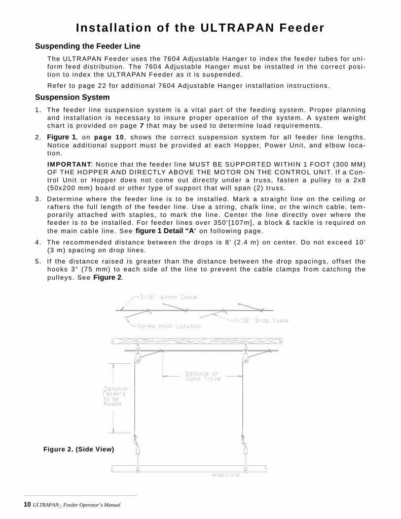
Instal lat ion of the ULTRAPAN FeederSuspending the Feeder Line
The ULTRAPAN Feeder uses the 7604 Adjustable Hanger to index the feeder tubes for uni -form feed d istr ibut ion. The 7604 Adjustable Hanger must be instal led in the correct posi -t ion to index the ULTRAPAN Feeder as i t is suspended.
Refer to page 22 for addi t ional 7604 Adjustable Hanger instal lat ion instruct ions.
Suspension System1. The feeder l ine suspension system is a v i tal par t of the feeding system. Proper p lanning
and instal lat ion is necessary to insure proper operat ion of the system. A system weightchart is provided on page 7 that may be used to determine load requirements.
2. Figure 1, on page 10 , shows the correct suspension system for a l l feeder l ine lengths.Not ice addi t ional support must be provided at each Hopper, Power Uni t , and e lbow loca-t ion.
IMPORTANT: Not ice that the feeder l ine MUST BE SUPPORTED WITHIN 1 FOOT (300 MM)OF THE HOPPER AND DIRECTLY ABOVE THE MOTOR ON THE CONTROL UNIT. I f a Con-trol Uni t or Hopper does not come out di rect ly under a truss, fasten a pul ley to a 2x8(50x200 mm) board or other type of suppor t that wi l l span (2) t russ.
3. Determine where the feeder l ine is to be instal led. Mark a stra ight l ine on the cei l ing orrafters the ful l length of the feeder l ine. Use a str ing, chalk l ine, or the winch cable, tem-porar i ly attached wi th staples, to mark the l ine. Center the l ine d i rect ly over where thefeeder is to be insta l led. For feeder l ines over 350’ [107m], a b lock & tackle is required onthe main cable l ine. See figure 1 Detail “A” on fo l lowing page.
4. The recommended distance between the drops is 8 ’ (2.4 m) on center. Do not exceed 10’(3 m) spacing on drop l ines.
5. I f the d is tance raised is greater than the dis tance between the drop spacings, offset thehooks 3" (75 mm) to each s ide of the l ine to prevent the cable c lamps f rom catching thepul leys. See Figure 2.
Figure 2. (Side View)

11 ULTRAPAN Feeder Operator’s Manual
Figure 1.
Suspension Layout Graphic
Detail “A”: Winch Installation andThrow-Back Detail
Detail “B”: Hopper Support Detail
Detail “C”: Hanger Installation Detail

12 ULTRAPAN Feeder Operator’s Manual
Figure 3. (Side View)
6. Refer to Figures 3 or 4 through 7 for speci f ic insta l lat ion instruct ions for the screw hooksand cei l ing hooks.
7. For insta l lat ions using wood t russes, standard screw hook or the opt ional Cei l ing Hookmay be used to hold the pul ley assembl ies.
8. For insta l lat ions using steel t russes, the Cei l ing Hooks are avai lable to hold the pul leyassembl ies.
Screw Hook Installation1. Screw the hook into the truss the fu l l length of the threads to prevent bending. 2. The openings of the screw hooks must be pointed away from the d i rect ion of t ravel when
the Power Winch ra ises the feeder l ine. See Figure 3 .
Ceiling Hook Installation
1. The cei l ing hook may be used in a var iety of insta l la t ions. Depending on your cei l ing orrafter type, instal l the Cei l ing Hooks as shown in Figures 4 - 7.
2. Af ter secur ing the Ceil ing Hook to the t russ, s l ide the hook of a Swivel Pul ley into theslot, as shown in Figure 8.
Figure 4.

13 ULTRAPAN Feeder Operator’s Manual
Figure 8. (End View)
Figure 5. Figure 6.
Figure 7.

14 ULTRAPAN Feeder Operator’s Manual
Power Winch Installation1. Attach the 2” x 8” [50 x 200mm] board, or angle i ron f ix ture, to the cei l ing at the center of the
feeder l ine. The 2” x 8”[50 x 200 mm] must be paral lel to the l ine and must span at least 3raf ters.
I f the hopper is located at the center of the feeder l ine, locate the winch support a few feetoffset f rom the center of the feeder l ine. However, the Winch Drum must be d i rect ly in l inewith where the main cable is to be insta l led.
2. Attach the Power Winch to the winch support 2”x8”[50 x 200mm] board or angle i ron f ix ture
Insta l l a Cable Hook (# 2985) between the mounting bol t and Power Winch frame, as shownin Figure 9.
3 . Extend the 3/16" (5 mm) cable the fu l l length of the feeder l ine. Attach the cable tempo-rar i ly to the cei l ing wi th nai ls , s taples, or some type of fasteners.
4. Wrap the cable through the winch drum re l ie f located near the bot tom of the drum. Tightenthe set screw to anchor the cable to the drum. See Figure 10.
Figure 9. (End View) Figure 10. (End View)
5. Turn the winch drum two fu l l revolut ion. Guide the cable against the f lange at the bot tomof the winch drum. The cable must not wrap over i tse lf on the drum, but should be wrappedas c lose as possible to each previous wrap. See Figure 11.
Figure 11. (End View)
1255-63 4/2001
Double Clamp these areas
Double back arrangement for feed lines over 350' [107 m]

15 ULTRAPAN Feeder Operator’s Manual
Drop Installation1. At tach a 3004 Pul ley to each hook.
2. Thread the end of the 3/32" or 1/8" cable through the pul ley toward the winch. Clamp th is end tothe 3/16" winch cable about 6" (150 mm) f rom the last pul ley, us ing a 3/16" cable c lamp. Seeappl icable f igure; Figure 3 or 8.
3. Al low enough cable length for insta l la t ion of the Adjustment Leveler.
Suff ic ient cable is inc luded to provide " throwbacks" on drops located beneath and near thewinch. Deta i l “A” in Figure 1 shows a " throwback" cable arrangement.
4. Begin instal l ing suspension drops at the winch and proceed to the ends of the feeder l ine. Keep the main cable t ight between drops. I t may be necessary to hang a weight on the end ofthe cable to maintain tension on the l ine.
Figure 3. (Side View)
Figure 8. (End View)

16 ULTRAPAN Feeder Operator’s Manual
Feeder Assembly Procedure1. All feeders assemble in the same manor. Refer to Figure 12 below. Insert the Reduction Tube into the Sup-
port Cone and slide the Support Cone Assembly, the Adjustment Cone, and the Grill together as shown inFigure 12. Hook the loop of the Grill to the tab of the Feeder Pan. Rotate the Feeder Pan over on the top ofthe Grill and Cones. Seat the Feeder Pan in the ring of the Grill. With the Feeder Pan fully seated rotate thepan clockwise to lock in place. Assemble the remaining Feeders.
Rotate the Feeder Pan to lock into the Grill
Feeder Pan
Reduction Tube
Support Cone
Adjustment Cone
C2 Plus Grill
896-79H
Feeder PanReduction Tube
Adjustment Cone
C2 Plus Grill
Rotate the Feeder Pan to lock into the Grill
896-91
Adjustable Grill
Optional Height Ring
Adjustable Grill Lock
Support Cone
Typical PanAssembly
Typical PanAssemblyWith AdjustableGrillFigure 13
Figure 12

17 ULTRAPAN Feeder Operator’s Manual
Note: Some appl icat ions may use the two-piece Model C2 Plus Feeders. For these appl ica-t ions, the feeders may be insta l led the same way by assembly the two-piece top onto thefeeder assembly before s l iding the feeder onto the tube.
2. Sl ide the pan assembly onto a feeder tube
3. Rotate the auger tubes so that the seam is down, th is holds the Pan Assembl ies in p lace onthe tubes, as shown in Figure 17.
4 . Set the pan assembl ies at the #4 adjustment posit ion. The arrow molded into the top of theAdjustment Cone should point to the #4 on top of the gr i l l .
5 . Beginning at the Hopper/Boot locat ion, posit ion the tube sect ions (wi th feeders at tached)end-to-end in approximately thei r f inal posi t ion, wi th the bel led end of the tubes opposi tethe d i rect ion of t ravel . See Figure 17
Figure 17. (Side View: Standing outside the loop.)
Feeder Line AssemblyNote: The auger must travel in a clockwise direction when standing inside the loop.1. Posi t ion the tubes end to end in approximately the f ina l locat ion of the l ine. The feeder
tubes should be insta l led so that the expanded end of each tube points in the oppositedi rect ion of auger t ravel . See Figure 18.
Figure 18. (Side View: Standing outside of the loop).

18 ULTRAPAN Feeder Operator’s Manual
2. Two-Hopper systems (systems wi th over 500’ or 152 m tota l auger length) must have hop-pers located as speci f ied in the Planning the System sect ion on page 7 and 8. Skip to step5 and refer to Figure 21.
Single-Hopper systems (systems wi th less than 500’ or 152 m tota l auger length) may havethe hopper located as speci f ied in Figure 20.
Chore-Time recommends locat ing the hopper in the center of the loop, as shown. However,the hopper may be instal led at the al ternate locat ion speci f ied. Refer to Figures 22 - 24 foral ternate hopper locat ion component layout d iagrams.
Figure 20. (Top View)3. Beginning at the Boot, assemble the Tube Connector, and Auger Tubes as shown in the
appropr iate d iagram.Note : The feed tubes should be instal led c lockwise around the system, star t ing at the out-le t end of one hopper, cont inuing through the elbows to the incoming end of the other hop-per.
Figure 21. Boot components for Recommended Hopper Location. (Side View: Standing inside the loop).
Figure 22. Boot components for Alternate #1. (Side View: Standing inside the loop).

19 ULTRAPAN Feeder Operator’s Manual
5. Remove the Power Uni t f rom the Base Connector Weldment and insta l l the Base ConnectorWeldment, as shown in Figure 23.
6. Loosen the four bol ts on the incoming s ide of the Power Uni t Base.
Sl ide the bel led end of the Tube Adapter in to the incoming s ide of the Power Unit Base.Tighten the four bol ts to secure the Tube Adapter to the Power Uni t Base. See Figure 23.Use a Tube Connector to connect the incoming st ra ight sect ion of auger tube to the TubeAdapter. Secure using a standard Clamp and an Ant i -Roost Clamp.
7. Loosen the four bol ts on the outgoing s ide of the Base Connector Weldment.
Sl ide the bel led end of the Tube Adapter in to the outgoing s ide of the Power Uni t Base.Tighten the four bol ts to secure the Tube Adapter to the Power Uni t Base.
8. Insert the bel led end of the next tube sect ion over the Tube Adapter, as shown in Figure23. Secure using a Clamp/Anti -Roost Bracket .
9. Cont inue insta l l ing auger tubes unt i l the e lbows are reached.
10. Assemble the e lbows and related components as shown in Figure 24. Temporar i ly supportthe e lbows unt i l the suspension system is instal led.
Instal l the (10) insulators around the e lbows, approximately as shown.
4. Cont inue assembling the feeder l ine unt i l a power unit locat ion is reached. Refer to sect ionmarked “Planning the System” on pages 7 and 8 to determine Power Uni t Locat ions forvar ious system length
Figure 23. (Side View): Standing outside the loop
Figure 24. (Side View)

20 ULTRAPAN Feeder Operator’s Manual
16. Insta l l the remaining auger tubes, power uni t bases, hopper, and elbows, the same as thef i rst .
17. Figure 25 shows the preferred locat ion of the serv ice sect ion.
Cut the bel led end of the auger tube leaving 15" (380 mm) between tubes to insta l l theService Sect ion.Approximately 4" (100 mm) of the auger tube seam wi l l need to be cut off to a l low the Ser-v ice Sect ion to be insta l led.
Secure the Service Sect ion Base to the auger tubes by s l id ing the tubes into the base andfastening the Service Sect ion Clamps on top using the 1/4-20 hardware suppl ied. Do notinsta l l the Service Sect ion Cover at th is t ime.
Figure 28. (Side View: Standing outside the loop),
ULTRAPAN Control FeederThe Proximi ty Intermediate Control uses a Proximi ty Switch to sense feed and cause thesystem to star t and stop. The Proximi ty Switch has sensi t iv i ty adjustment and delayadjustment screws. See Figure 28.The Proximity Intermediate Contro l is to be located just pr ior to the Feed Hopper. I f part ialhouse brooding is to be used, the Intermediate Contro l must be located on that s ide of thehouse next to the hopper on the return s ide of the feeder.
Do not hinder the b i rd movement around the Intermediate Contro l pan. Provide adequatel ight ing so that the b irds wi l l not shy away from the Intermediate Contro l area.
896-52H
Figure 28.

21 ULTRAPAN Feeder Operator’s Manual
1. Enlarge the out let hole where the contro l is to be insta l led on the tube. This wi l l ensuretota l feed dropout to the Intermediate Contro l . See Figure 29 for recommended s ize andplacement . Use hacksaw and t in snips to enlarge hole s ize. Be sure there are no burrs
Figure 29. (Side View)
ins ide the tube to catch the auger.
2. Instal l the Intermediate Control :a. Remove the two hex head screws on the Control Top.
b. Li f t off the Contro l Top.
c. Cradle the feeder tube in the contro l housing. The feeder tube may have to be turned toal low the pan to hang stra ight.
d. Clamp the contro l in p lace by insert ing tabs on the Contro l Top into the s lots on theControl Body. Insta l l and t ighten the two hex head screws that were removed ear l ier.
Figure 30. (Side View: Standing outside the loop).

22 ULTRAPAN Feeder Operator’s Manual
Figure 31.
Adjustable Hanger InstallationThe Adjustable Hanger used wi th the ULTRAPAN Feeder enables the operator to index thefeeder l ine. Use the chart on page 30 to determine hanger sett ings for your instal la t ion.
Note: The chart on page 30 is for use on standard (2) hopper systems where the hoppersare located near the center of the feeder loop.
Figure 32 shows how the set t ing numbers (C1, C2, etc.) f rom the chart re late to the Adjust-able Hanger. Example: The Hanger in Figure 32 is set to “D5.”Insta l l the adjustable hanger to each tube at the suspension drop locat ion. Use the appro-pr iate Indexing Chart on page 30 , to determine proper hanger sett ing for each indiv idualtube as i t is being instal led.
ImportantWhen insta l l ing the Hangers, make
sure;
1)to work in the d irect ion ofauger travel , and2)the stamped numbers arefacing the outgoing s ide of thehopper
Figure 32.Note: The Hanger MUST be installed properly for the system to properly dispense feed into the feeder pans.

23 ULTRAPAN Feeder Operator’s Manual
Indexing the TubesBeginning at the hopper, use a marker to number the feeder tubes. Begin with Tube 1 comingout of the hopper, then 2, 3, and so on, cont inuing unt i l each tube in the l ine is marked. Do notinc lude e lbows in tube count.
The maximum number of tubes for systems using 9’ Auger Tubes is 56. The maximum numbertubes for systems using 10’ Auger Tubes is 50 . The maximum number of tubes for systemsusing 12’ Auger Tubes is 42 .
F ind the heading for the number of tubes on the feeder l ine in the hor izonta l l ine at the top ofthe indexing chart . The cor rect hanger adjustments for each feeder tube are show in the col -umn under the appropr iate heading.
Installing Tube Clamps and Anti-Roost BracketsBeginning at the boot, place a c lamp/ant i - roost bracket on the f i rs t tube connect ion. For9-f t . [2 .7m] and 10ft . [3m] feeder tubes; p lace a standard c lamp on the next four tubejo ints- then use a c lam/ant i - roost bracket on the f i f th.
For 12ft . [3.6m] feeder tubes; place a standard c lamp on the next three tube joints- then use aclamp/ant i- roost bracket.
Do not tighten the clamps at this time.Cont inue insta l l ing the c lamps and ant i - roost brackets us ing the above spacing procedure.Ant i- roost brackets are used on each s ide of the dr ive uni ts and at the e lbows so the spacingprocedure wi l l be repeated again fo l lowing these components. Insta l l c lamps to the ent i re sys-tem.
Figure 33. (Top View)
Figure 34. (Side View)

24 ULTRAPAN Feeder Operator’s Manual
Auger InstallationNote: Use extreme caution when working with the auger. The auger is under tension and
may spring causing personal injury. Wear protective clothing, gloves, and safetyglasses when working with the auger.
To avoid k inking the auger, be carefu l not to drop the rol led auger when handl ing. Inspectthe auger carefu l ly as i t is instal led. Small k inks may be st raightened. Large k inks must beremoved and the auger brazed back together.
Cut the leading 18”[450mm] and last 18”[450mm] off each ro l l o f auger. Also, cut out anyother destroyed auger sect ions and reconnect the auger as speci f ied in the Auger Connec-tor or Auger Brazing sect ion of th is manual .
In preparat ion for the auger instal la t ion, complete the fo l lowing:
• The Power Uni t and Dr iver Assembl ies) must be removed f rom the Base Connector Weld-ment . An Auger Dr iver must be instal led on each Base Connector Weldment . See Figure35.
• The Service Sect ion Cover must be removed to instal l the auger.
1. Begin feeding one end of the auger in to the auger tubes through the Service Sect ion. Chore-Time recommends always feeding the auger into the tubes from the outside ofthe coil ( this has a plastic cap on the end of the auger.) This wil l insure the augerfl ightings wi l l match. Push the auger, by hand, to the f i rs t Auger Dr iver. The Auger Dr iver may then be used topul l the auger through the tubes. An Auger Dr iver should be instal led at each motor loca-t ion to a id in pul l ing the auger around the system. See Figure 35.
2. I f more than one auger is to be insta l led, the ta i l end of the f i rs t auger and the leading endof the second auger must be connected wi th an Auger Connector.
Figure 35. (End View)
KEEP HANDS AWAY FROM PINCH POINTS WHEN INSTALLING
AUGER.DO NOT USE THE MOTORS TO
PULL THE AUGER!
CAUTION

25 ULTRAPAN Feeder Operator’s Manual
3. Continue insta l l ing auger unt i l i t reaches the Service Sect ion.4. Cut excess auger off co i l , Leave enough auger to work wi th when stretching and connect-
ing the auger.
5. Pul l on one end of the auger unt i l the other end moves. Release the auger and al low i t torelax to i t ’s f ree length.
6. Use locking p l iers to hold one end of auger in p lace whi le stretching the auger. See Figure36.
A l low approximately 4” to 6” (100 to 150 mm) of auger to extend past the locking p l iers toal low for Auger Connector (or brazing) insta l lat ion.
Locking PliersLocking Pl iers
7. Determine the amount of s tretch required.
The amount of s tretch required is 6" per 100’ (150 mm per 30 m) of to ta l system length.For example: I f the system has an overal l system length of 300’ (91.4 m), the requiredauger stretch is 18" (460 mm).
8 . From the re laxed posi t ion, s t retch the auger (as determined by step 7, above) by pul l ingon the loose end.
9. Mark the auger where i t is to be cut . 10. Pul l another 18” (450 mm) of auger and insta l l another set of lock ing p l iers to keep the
auger from spr inging back into the auger tube. See Figure 31.
11. Cut the auger at the mark. Fi le the end of the auger smooth so that there are no sharpedges.
Make sure the auger is not deformed or twisted f rom cutt ing. Deformed auger wi l l notmatch wel l wi th the other end of the auger and may cause problems passing through DriveUni ts.
Auger Connector InstallationThe Auger Connector is designed to fasten the ends of ULTRAPAN Auger together wi thoutwelding. NOTE: I t is not to be used wi th rotat ing auger system.
1. Screw the Auger Connector in to one end of the auger. 2. Untwist the remain ing end of the auger 1-1/2 turns so that when i t is threaded into the f i rs t
end of the auger i t wi l l return to i ts relaxed posi t ion. Auger ends must be over lapped—NOTbutted, when threaded into the t rack of the Auger Connector. See Figure 36 .
Figure 36. (Side View)
Figure 36. (Side View)

26 ULTRAPAN Feeder Operator’s Manual
3. Stretch the auger and twist the auger ends together. Both ends of the auger should beeven wi th the end of the Auger Connector.
4. Tighten each set screw unt i l i t touches the auger, then t ighten an addi t ional 3/4 turn MAX-IMUM.Be careful not to over t ighten the setscrews and deform the auger. Over t ighteningthe setscrews may cause the auger to jam up in the power units .
5. F i le both ends of the auger so that they are the same diameter as the rest of the auger.
Alternative Auger Connection - Auger BrazingThe feeder auger may be brazed according to these instruct ions to obta in a strong joint.
Screw the auger together about 120 degrees ( 1/3 turn) and secure in the Welding F ixture.See Figure 37.
S lowly heat the auger and apply a braze to the inside of the auger. Al low i t to cools l ight ly, then rotate the Welding Fixture and braze the outside of the auger.The braze should extend from 1/8" to 1/4" (3 to 6 mm) f rom the end of each auger. DONOT BRAZE ALL THE WAY TO THE END. This a l lows the auger to f lex in e i ther d irect ionas i t t ravels around the e lbows wi thout becoming weakened. See Figure 38.
Welding FixtureFigure 37. (Side View)
THINGS TO REMEMBER• To insure a good braze, clean dirt, oil, etc., off both ends of the auger.
• A bronze, flux coated filler rod is recommended.
• The joint should be smooth and well filled.
• Do not over heat the auger; apply just enough heat to melt the filler rod.
• Allow the auger to air cool.
• File all edges smooth.
• The outside diameter of the auger at the braze should not be larger than the rest of the auger.
Figure 38. (Side View)

27 ULTRAPAN Feeder Operator’s Manual
Suspending the Feeder1. Assemble the hopper to the boot us ing the bot tom rai ls of the hopper, as shown in Figure
39. Hardware (1/4-20) is suppl ied to hold the boot in place on the hopper rai ls .
2. A Cable assembly ( inc luding 20ft . [6m] of cable, a s leeve c lamp, and a 5/32” th imble) issuppl ied to suspend the hopper. Figure 39 shows the suspension components assembled.The pin should be located through the top hole of the adjustment brackets.
Side PanelCable Assembly
Adjustment Bracket
ThimbleClevis & Hair Pins
3. Li f t the hopper and boot assembly up to the point the feed pans just c lears the f loor. Blockup the boot to th is posi t ion.
4. Feed the free end of the hopper support cable through the hopper suspension pul ley, pul lthe cable to remove the s lack, and attach to main cable. Cable wi l l now support the hopperand block can be removed.
5. Insta l l the tube suppor t k i t as shown in Figure 40. The drop tube is suppl ied with the f i l lsystem.
Figure 39. (Tope View of Hopper)
Figure 40.

28 ULTRAPAN Feeder Operator’s Manual
Use the large holefor 1/8" cable. Usethe smal l hole for3/32" cable.
Figure 41.
6. Start ing at the hopper (winch i f the hopper is p laced at the end of the bui ld ing), begin sus-pending the feeder tubes by using the cable adjuster and drop cable. Figure 42 shows theproper use of the cable adjuster.
7. Use the index chart on page 30 to determine the proper sett ing to p lace the cable throughthe adjustable hangers. Figure 42 shows how the sett ing numbers(C1, C2, etc.) f rom thechart re late to the adjustable hanger. Example: the hanger in Figure 42 is set to “D5”.
Figure 42.

29 ULTRAPAN Feeder Operator’s Manual
8. As the cable is at tached to each adjustable hanger, raise the feeder tube unt i l the feederjust c lear the f loor. This procedure wil l remove the s lack cable as you proceed to each endof the system.
9. Attach the cable suspension system to the dr ive uni ts and elbows. Addi t ional suspensiondrops must be instal led to support the dr ive uni ts and e lbows as shown in the SuspensionLayout Graphic, Figure 1, Page 10. Use the #4207 hanger to support the elbows.
10 Fol lowing insta l la t ion of al l drops, check the drop cables before ra is ing feeder l ines. Cablemust be proper ly tracking on a l l pul ley before ra is ing the feeder l ine.
11. Raise the feeder l ine to a convenient working height.
12. With the feeder l ine suspended, measure from the f loor or cei l ing to the auger tubes tolevel the system. Make sure each tube is level (not sagging, s loping, etc. ) .
Indexing the TubesNote: When indexing the tubes, index from the outgoing side of one hopper, around the
elbows to the incoming side of the next hopper. Repeat the procedure on the remain ing
sect ion of tubes and elbows. See Figure 33.
1. Leave the tube clamps loose, unti l the l ine has been indexed.2. Use the chart (page 30) for indexing the tubes.
Find the heading for the number of tubes in your feeder l ine in the hor izonta l l ine at thetop of the indexing chart . The correct hanger adjustments for each feeder tube are shownin the column under the appropr iate heading.
3. The Adjustable Hangers have been set dur ing the suspension process, Check the set t ingwith the Indexing Gauge to f ine tune the l ine.
Start at the hopper. Standing down the feeder l ine looking back at the outgoing end of thehopper, the indexing gauge should be p laced wi th the notch over the cr imped port ion ofthe tube with the gauge on the r ight s ide of the feeder tube ( Indexing Gauge wi l l be out-s ide the loop). The Indexing Gauge should be p laced between the second and th i rd holeon the f i rs t tube.
Figure 33. (Top View)

30 ULTRAPAN Feeder Operator’s Manual
5. Start ing wi th tube number 1, set the c lear pointer on the gauge to the proper set t ingaccording to the indexing chart . Rotate the tube unt i l the bubble in the leveler comes tothe center. Instal l and t ighten the c lamp, as shown in Figure 43, on the bel l toward thehopper.
NOTE: I f the tube must be rotated so much that the Adjustable Hangers are t i l ted too far toone s ide or the other, check the fo l lowing:
a. Make sure the Adjustable Hanger is set according to the indexing chart on page 30.b. Make sure the Indexing Gauge is proper ly posi t ioned on the tube. The Indexing Gauge
must always be to outs ide the loop. I t is common mistake to swi tch the Indexing Gaugeto be located ins ide the loop af ter a corner.
c. Make sure the Indexing Gauge is placed on the tube cor rect ly. See point 4.
d. Make sure that the sett ings for both the Indexing Gauge and the Adjustable Hangers aretaken from the correct column from the chart for length of auger tube being indexed.
6. Cont inue to set the remainder of the l ine in the same manner. Af ter each tube has beenset, t ighten the c lamp on the bel led end toward the hopper. Take care to insure that thetubes al ready set, do not move. (This wi l l require a second person to hold the end of thetube that has just been set whi le you turn the next tube to be set .)
Posi t ion the c lamps on the tube jo ints, as shown in Figure 43.
NOTE: When rotat ing the tubes, hold the tubes a l ready indexed from moving. Use twolarge adjustable p l iers or p ipe wrenches to gr ip the tube. Be carefu l not to deform thetubes.
7. Insta l l Ant i -Swing Camps.
Figure 43. (Side View)

31 ULTRAPAN Feeder Operator’s Manual
56
B6B6B6B7B7B7B8B8B8B9B9B9C1C1C1C2C2C2C3C3C3C4C4C4C4C5C5C5*C5C6C6C6C6C6C6C6C7C7C7C7C8C8C8D1D1D1D2D2D2D3D3D3D4D4D4D5
44
B7B8B8B9B9B9C1C1C1C2C2C2C3C3C3C4C4C4C5C5C5C6*C6C6C7C7C7C8C8C8C8D1D1D1D2D2D2D3D3D3D4D4D4D5
28
C1C1C2C2C3C3C4C4C5C5C6C6C6C6*C7C7C8C8C8D1D1D2D2D3D3D4D4D5
12
C1C2C3C4C5C6*C7C8D2D3D4D5
14
C1C2C2C3C3C4
C5*C6C7C8D2D3D4D5
16
C1C2C2C3C3C4C4C5*C5C6C7C8D2D3D4D5
18
C1C2C2C3C3C4C4C5C5*C6C6C7C8D1D2D3D4D5
20
C1C1C2C2C3C3C4C4C5C5*C6C6C7C7C8D1D2D3D4D5
22
C1C1C2C2C3C3C4C4C5C5C6*C6C7C7C8C8D1D1D2D3D4D5
24
C1C1C2C2C3C3C4C4C5C5C6C6*C7C7C8C8D1D1D2D2D3D3D4D5
26
C1C1C2C2C3C3C4C4C5C5C6C6C6*C7C7C8C8D1D1D2D2D3D3D4D4D5
30
B8C1C1C2C2C3C3C4C4C5C5C5C6C6C6*C7C7C7C8C8C8D1D1D2D2D3D3D4D4D5
32
B8B8C1C1C2C2C3C3C4C4C5C5C5C6C6C6*C7C7C7C8C8C8D1D1D1D2D2D3D3D4D4D5
34
B8B8C1C1C2C2C3C3C4C4C4C5C5C5C6C6C6*C7C7C7C8C8C8D1D1D1D2D2D2D3D3D4D4D5
36
B8B8C1C1C2C2C2C3C3C3C4C4C4C5C5C5C6C6*C6C7C7C7C8C8C8D1D1D1D2D2D2D3D3D4D4D5
38
B8B8C1C1C1C2C2C2C3C3C3C4C4C4C5C5C5C6C6*C6C7C7C7C8C8C8D1D1D1D2D2D2D3D3D3D4D4D5
40
B8B8B9C1C1C1C2C2C2C3C3C3C4C4C4C5C5C5C6C6*C6C7C7C7C8C8C8D1D1D1D2D2D2D3D3D3D4D4D4D5
42
B8B8B9B9B9C1C1C1C2C2C2C3C3C3C4C4C4C5C5C5C6*C6C6C7C7C7C8C8C8D1D1D1D2D2D2D3D3D3D4D4D4D5
123456789
1011121314151617181920212223242526272829303132333435363738394041424344454647484950515253545556
Number Of Tubes
* Represents Center Of Elbows
123456789
1011121314151617181920212223242526272829303132333435363738394041424344454647484950515253545556
46
B6B7B7B8B8B8B9B9B9C1C1C1C2C2C2C3C3C3C4C4C4C5C5*C5C6C6C6C7C7C7C8C8C8D1D1D1D2D2D2D3D3D3D4D4D4D5
48
B6B6B7B7B7B8B8B8B9B9B9C1C1C1C2C2C2C3C3C3C4C4C4C5*C5C5C6C6C6C7C7C7C8C8C8D1D1D1D2D2D2D3D3D3D4D4D4D5
50
B6B6B6B7B7B7B8B8B8B9B9B9C1C1C1C2C2C2C3C3C3C4C4C4C5*C5C5C6C6C6C7C7C7C7C8C8C8D1D1D1D2D2D2D3D3D3D4D4D4D5
52
B6B6B6B7B7B7B8B8B8B9B9B9C1C1C1C2C2C2C3C3C3C4C4C4C5C5*C5C5C6C6C6C6C7C7C7C7C8C8C8D1D1D1D2D2D2D3D3D3D4D4D4D5
54
B6B6B6B7B7B7B8B8B8B9B9B9C1C1C1C2C2C2C3C3C3C4C4C4C4C5C5*C5C5C6C6C6C6C7C7C7C7C8C8C8C8D1D1D1D2D2D2D3D3D3D4D4D4D5
Tube
Num
ber
Indexing Chart for ULTRAPAN FeedersFor standard (2) hoppers systems.

32 ULTRAPAN Feeder Operator’s Manual
Anti-Roost Installation1. Unrol l the bulk ant i - roost cable. Note: I f the cable is
unrol led as shown in Figure 44, tak ing 5 loops of the coi l with one hand, then changing hands to remove 5 loops as i t is unrol led, i t wi l l l ie f lat dur ing insta l la t ion.
2. Start at the hopper end of the l ine and form a loop around the ant i - roost bracket . For best resul ts , make a double loop around the ant i - roost insulator in the center groove of the insulator and fasten wi th a 1/16" cable c lamp as shown in Figure 45.
3 . Insert the cable in the insulator on the top of each Gri l l Support between the hopper and the next ant i- roost bracket.
4. Attach a spr ing in the center groove at the second ant i - roost bracket and cut the cable at this point . See Figure 46.
5. Thread the ends of the cable through the end of the spr ing. Pul l the cable t ight so that there is 3/4" to 1" [20 to 25 mm] of stretch in the spr ing. Clamp the cable to form a loop and cut off any excess. See Figure 46.
6 . At tach the cable to the insulator. For best resul ts, make a double loop around the ant i - roost insulator in the center groove of the insulator and fasten wi th a 1/16" cable c lamp as shown in Figure 46.
7 . Run the cable to the next insulator, at tach a spr ing in the center groove at the ant i - roost bracket and cut the cable at th is point. The cable should be posit ioned in the insulator bui l t in to the top of each gr i l l support a long the feeder l ine.
8. Repeat th is insta l lat ion a long the ent i re feeder l ine to the dr ive uni ts and e lbows.
Shock2 3/98
Figure 44. Unrolling the Cable
1255-102 9/2000
2) Clamp with InsulatorBracket and Insulator
1) Cable Clamp
3) Anti-Roost Cable
Figure 45. Anti-Roost Cable at the Hopper
1255-103 9/2000
1) Cable Clamp4) Spring should be stretched3/4" to 1" [19 mm to 25 mm]
3) Anti-Roost Cable
1) Cable Clamp2) Clamp with InsulatorBracket and Insulator
Figure 46. Anti-Roost Cable Mid-Line Connection

33 ULTRAPAN Feeder Operator’s Manual
9. Instal l the Ant i-Roost Guard on the power uni t insulators. Be sure the wire snaps into thereta iners molded into the insulators.
10. Pul l the cable t ight so that there is 3/4" to 1" (19 to 25 mm) of s tretch in the spr ing. Clampthe cable to form a loop. Thread the excess cable through the spr ing and c lamp toAnt i -Roost Wire. See Figure 47.
11. Attach the cable to the insulator on the outgoing s ide of the power uni t. For best resul ts,make a double loop around the center groove of the Ant i -Roost insulator and fasten with a1/16" cable c lamp as shown in Figure 47.
12. Run the cable to the next Ant i -Roost Clamp. At tach a spr ing in the center groove at the An-t i -Roost Bracket and cut the cable at th is point . The cable should be posi t ioned in the in-sulator bui l t in to the top of each Gr i l l Support along the feeder l ine.
13. Repeat th is insta l la t ion unt i l the Ant i -Roost cable is insta l led a long the feeder l ine, unt i l acorner is reached.
14. Ant i -Roost Clamps must be instal led around the elbows, as shown in Figure 48.
The Ant i-Roost Wire is provided to be used around the elbows. Snap i t down in the centergroove of the insulators on the elbows, and on the insulators immediate ly before and afterthe e lbows. See Figure 48.
Insta l l a jumper wire from the shocker cable to the Ant i -Roost Wire, us ing a cable c lamp,suppl ied.
Figure 47. (Side View)
Figure 48. (Top View)

34 ULTRAPAN Feeder Operator’s Manual
15. Cont inue instal l ing the Ant i -Roost cable, spr ing, etc. , simi lar ly around the system.
16. Insta l l the h igh-vol tage wire from the insulator on one s ide of the boot to the insulator onthe other s ide of the boot . See Figure 49.
17. Attach the L ine Charger to the s ide ofthe feeder tube wi th two tube c lamps,inc luded in the parts package. Connectthe charge cable to the Ant i -Roost l ineusing the cable c lamp suppl ied. SeeFigure 50.
Use only the vol tage l is ted on the L ineCharger to operate i t . Provide somemeans of d isconnect ing the power tothe L ine Charger; a swi tch near thedoor to the bui ld ing is a good idea, orp lug and receptacle may be used.
Figure 49. (Side View)
Figure 50.

35 ULTRAPAN Feeder Operator’s Manual
Part #41020Deep
Part #42016Shallow
893-93
P r o x i m i t y I n t e r m e d i a t e C o n t r o l
C A U T I O NT h e e q u i p m e n t m a y s t a r t a u t o m a t i c a l l y .
D i s c o n n e c t e l e c t r i c a l p o w e r p r i o r t os e r v i c i n g t h e e q u i p m e n t .
K e e p h a n d s a n d t o o l s c l e a r o ft h e a u g e r a t a l l t i m e s .
IntroductionThe Proximi ty Intermediate Control w/Off Delay was designed to provide im-proved feeding in ULTRAPAN® Breeder Feeder Systems.
Do not hinder bird movement around the Intermediate Control . Provide ade-quate l ight ing so that the birds wi l l not shy away from the In termediate Contro l .

36 ULTRAPAN Feeder Operator’s Manual
OperationWhen the switch senses feed, the Delay is act ivated immediately. The system wi l l cont inue to run unt i lthe de lay has expired. When feed is removed, the system is act ivated.
Setting the DelayThe Proximity Swi tch includes an adjustable delay. The delay may be set f rom 1 second to 10 minutes.
A. Use a smal l screw dr iver provided to turn the Delay Adjustment Screw (see Figure 4). Turn thescrew counter c lockwise unt i l the l ight stays on. Turn the screw clockwise one complete revolu-t ion. Th is sets the delay to 1 second.
B. To increase the delay, turn the Delay Adjustment Screw clockwise.
Watch the indicator l ight; quick f lashes = shor ter t ime delay, s low f lashes = longer t ime delay.
Adjusting the Sensit ivi tyThe Proximity Switch is shipped with the sensi t iv i ty preset at the factory. This set t ing is adequate formost feed types and condi t ions. However i f the sensi t iv i ty does need to be adjusted, careful ly fol low theseinstruct ions:
A. Al low power to be suppl ied to the switch for at least 15 minutes to proper ly warm the sensor. Seethe wir ing diagrams in this manual.
B. Set the Proximi ty Switch t ime delay to 1 second as speci f ied above.
C. Use a smal l screw dr iver to remove the caulk conceal ing the Sensi t iv i ty Adjustment Screw.
D. Greater swi tch sensi t iv i ty is achieved by turning the Sensi t iv i ty Adjustment Screw clockwise.
Less switch sensi t iv i ty is achieved by turning the Sensi t iv i ty Adjustment Screw counterclockwise.
Note the screw or ientat ion before beginning adjustment. Adjust the Sensit iv i ty Adjustment Screw1/4 turn, test switch, cont inue adjust ing as requi red.
Figure 4. Proximi ty Switch Adjustments (end v iew of Prox imi ty Switch) .

37 ULTRAPAN Feeder Operator’s Manual
P r o x i m i t y I n t e r m e d i a t e C o n t r o l I n t e r n a l W i r i n g
P r o x i m i t y S w i t c h S c h e m a t i c
Important: This wiring schematic represents the switch in the non-powered condition. When power is applied the N.O. and N.C. contacts reverse. Refer to the wiring diagrams, above, when wiring the Proximity Switch.

38 ULTRAPAN Feeder Operator’s Manual
System Overview for use with Wiring Diagrams
WIRING NOTES
Disconnect electrical power before inspecting or servicing the equipment, unless the maintenance instructions specifically state otherwise.
Wire the electrical equipment according to the wiring diagrams in this manual.
All field electrical wiring must be done by a qualified electrician, according to local and national codes.
Do not operate the equipment without the covers and guards properly positioned.
Failure to do so may cause personal injury or damage the equipment.
Ground all electrical equipment.
Note: Refer to this diagram as required to determine thelocation of Power Units, Switches, Control Units, etc.Each components is coded with a M1, S2, etc. (that’sMotor #1, Switch #2).

39 ULTRAPAN Feeder Operator’s Manual
ULTRAPAN Feeder System Wiring Diagram (Using Chore-Time Mechanical WEIGH-MATIC Scales)
ELECTRICAL SPECIFICATIONSVoltage: 230 - Hz: 50 / 60 - Phase : Single

40 ULTRAPAN Feeder Operator’s Manual
ULTRAPAN Feeder System Wiring Diagram(Using Chore-Time Mechanical Weigh-Matic Scales)
Continued on next page.
ELECTRICAL SPECIFICATIONSVoltage: 3 X 220 V
3 X 380 V + N3 X 415 V + N
Hz: 50

41 ULTRAPAN Feeder Operator’s Manual
Continued on next page.
Continued from previous page.

42 ULTRAPAN Feeder Operator’s Manual
Continued from previous page.

43 ULTRAPAN Feeder Operator’s Manual
ULTRAPAN Feeder System Wiring Diagram(For other brand scales without limit devise)
Continued on page 51.
ELECTRICAL SPECIFICATIONSVoltage: 3 X 220 V
3 X 380 V + N3 X 415 V + N
Hz: 50

44 ULTRAPAN Feeder Operator’s Manual
Digital Weigh-Matic Scales / ULTRAPAN Feeder Control Wiring Diagram

45 ULTRAPAN Feeder Operator’s Manual
Operat ion of the FeederThe ULTRAPAN Feeder is a c i rculat ing feeder, designed to supply a l l the feeder pans onthe system simul taneously. The Auger Tubes are indexed to insure even dist r ibut ion of thefeed through out the system. The auger is dr iven by hardened sprockets on the poweruni ts spaced evenly around the system.
Channel 2 of the 34380 Breeder Control or the MANUAL FILL swi tch wil l f i l l the hoppers.Channel 1 of the Breeder Contro l operates the feeders. The feeders wi l l operate unt i l thecontro l pan has been sat is f ied. The feeder l ines are a lso contro l led by the lower HoppersSwitch. This switch assures that the l ines retain their charge. The f i l l system is contro l ledby the weigh bin. When the b in reaches “0” the system wi l l s top f i l l ing the hoppers.
34380 Breeder ControlThe 34380 Breeder Control must be mounted ins ide the house in a convenient locat ion,out of reach of the bi rds.The Breeder Contro l is used with the WEIGH-MATIC Scale and Fi l l System and theULTRAPAN Feeding System to accurate ly weigh and del iver a preset amount of feed perday for breeder bi rds.
The contro l ut i l izes an Agr i -Timer t ime board wi th a permanent battery backup that keepsthe c lock on t ime in the event of a power outage. Even your ex ist ing program is stored inhard memory. The battery is accessib le and may be replaced i f necessary. Refer to themaintenance sect ion on page 76.
Refer to Instruct ion MF1061 (shipped wi th the Contro l) for programming information andoperat ion of the Contro l .
Balancing the Mechanical ScalesAl l f i l l system wir ing MUST BE COMPLETED before attempting to balance the scale.Never balance the scales i f any of the del ivery or f i l l augers are empty. The Weigh Binshould have approximately 50 pounds (22.6 kg) of feed in i t whenever the scales are bal -anced.
1. Turn switch "ON" at the Breeder Contro l .
2. Hold weight beam down and momentar i ly press swi tch button in beam box. This starts thef i l l system and i t w i l l br ing feed into the weigh b in. Run del ivery system long enough tobr ing 200 to 300 pounds (90.7 to 136 kg) of feed into the bin. Del ivery capaci ty of theModel 90 Auger is approximately 100 pounds (45 kg) per minute. Run the f i l l system theappropr iate length of t ime to achieve 200 to 300 pounds (90.7 to 136 kg) of feed in theweigh bin.
3. Release the Weighbeam and al low i t to ra ise up, away f rom the lower proximi ty sensor.The f i l l system wi l l s top.
ELECTRICAL SPECIFICATIONSfor the 34380Control Panel
—Contactor Outputs—230 VAC / 25 amps, 2 HP each
—Fuses—3 amp maximum (each)

46 ULTRAPAN Feeder Operator’s Manual
4. Program the Feeder Control Panel, according to the MF1061 Instruct ion, to a l low theincoming f i l l system to star t (when the Weighbeam moves to the upper proximity sensor) oruse manual f i l l opt ion.
5. Raise the Weighbeam so that i t moves to the upper proximi ty sensor. The del ivery systemthat carr ies feed from the weigh b in to the bui ld ing wi l l s tar t .
6. Run al l but about 50 pounds (22.6 kg) of feed f rom the weigh b in. Some feed MUST remainin the boot . THIS WILL BE THE ZERO POINT FOR BALANCING THE SCALE.
7. Turn swi tch "OFF" at the control before making balancing adjustments.8. Move poise on Weighbeam to "0" against the stop pin.
9. Sl ide back Balance Assembly a long the Weighbeam unt i l the end of the Weighbeam is cen-tered midway between the two sensors. Lock the back Balance Assembly to the Weigh-beam.
. I f f iner adjustment is required, adjust the brass rod on the Back Balance unt i l the Weigh-beam is centered between the two sensors.
10. Check the accuracy and balance by set t ing the system for a smal l quant i ty of feed (20pounds or 9 kg, for example) . Cycle the f i l l system and make the fo l lowing checks:
• Check Weighbeam so that i t does not over- t ravel or f loat when moving from an unbal-anced posi t ion to the balance point .
• Check the quant i ty of feed del ivered by cycl ing and col lect ing feed from the weigh b in.Number of pounds or k i lograms del ivered should be the amount at which the scale wasset.
Operation of the Scale1. Make sure the t ime c lock on the Breeder Contro l Panel is set to the present t ime.
2. Program the start ing t ime and length of the feeding per iod for the Feeder(channel #1) .For the F i l l System, set for the same start t ime and the length of t ime for 3 minutes(chan-nel #2)
3. Set the poise on the Weighbeam for the desi red quant i ty of feed. 4. Momentar i ly press swi tch but ton on the beam box unt i l the FLEX-AUGER system br inging
feed into the weigh bin star ts. The FLEX-AUGER system wi l l t ransfer the desi red quant i tyof feed into the weigh bin; then i t wi l l shut off automatical ly.
5. Set poise to zero AFTER THE WEIGHBEAM REACHES THE BALANCE POINT AND THEFLEX-AUGER SYSTEM STOPS.
6. The feeder is control led by channel #1 on the Breeder Control . I t wi l l s tar t running whenthe t ime c lock s ignals that feeding per iod should begin. They wi l l cont inue to run as longas feed is avai lable or to the end of the programmed feeding t ime.NOTE: Adequate t ime should be programmed for the feeder so that al l o f the measuredfeed is consumed dur ing each feeding per iod. Moni tor the feed consumption. I f the mea-sured amount of feed has not been dispensed f rom the weigh b in and/or the feed in thefeeder l ine hoppers has not fed down to where the lower hopper swi tches cut the l ine off ,then increase the length of feeding t ime.
Lower Hopper Swi tches wi l l shut off indiv idual l ines as they become empty as the mea-sured amount of feed is dispensed.
The f i l l system is contro l led by channel #2 of the Breeder Control . A short per iod of runt ime is a l l that is required to act ivate the weigh system. The weigh system locks in the Fi l lSystem unt i l the desi red feed rat ion is depleted
7. The operator must manual ly set the scales to the amount required for next feeding andpush the momentary swi tch to star t f i l l ing the weigh b in for the next feeding. Refer to "Operat ion of the Scales" and "Opt ional F i l l System Operat ion" for fur ther detai lson running the scales/ f i l l system.

47 ULTRAPAN Feeder Operator’s Manual
Start-Up ProcedureFollow this procedure with new and refilled houses.
NOTE: The fo l lowing procedure is to be run on each loop indiv idual ly. Therefore, d isconnectpower at each power uni t on the loop not being started. Also, f l ip the appropr iate Con-tro l Unit Toggle Switch to the OFF posi t ion.
1. Set the POWER switch to the ON posi t ion.
Push and hold the MANUAL FEED swi tch for manual operat ion. Al low the feeder to runlong enough to c lean al l the fore ign mater ia ls ( i .e. sawdust, d i r t ) out of the auger tubes.Release the swi tch to stop the feeder.
Repeat the above for the other feeder loop(s).
2. Move feed into the weigh bin.Open the weigh b in s l ide approximately 3 inches (75 mm).
3. Start the system by sett ing the POWER swi tch to the ON posi t ion.
Push the "MANUAL FILL" but ton on the Breeder Control , to star t the f i l l system. NOTE: Run the Fi l l System manual ly to a l low approximately 50lb.[23kg] of feed increments
into the hopper. Stop the F i l l System per iodical ly. This wi l l al low the feed to beremoved from the hopper and prevent over charging the feeder loop
Use the Contro l Uni t Toggle Switch to turn the f i l l system on and off , as required, toprevent over loading the "unpol ished" augers wi th feed.
4. Turn off e lect r ica l power to the system.6. Repeat the start-up procedure, above, on the second feeder loop.
ULTRAPAN Management Guidel inesThe ULTRAPAN Feeding System is designed for control led dis t r ibut ion of feed to broi lerbreeder pul lets and layers. The system ut i l izes indexed tubes for a uni form, constant , andfast feed del ivery immediately to a l l the feed pans. The Model C2 PLUS® Breeder Ser iesFeed Pan Assembly is designed to provide opt imum feed f low and to mainta in a low levelof feed to deter feed wastage. The C2 PLUS features a feed volume reduct ion tube and afeed cone wi th feed f ins to provide improved feed convers ions when compared to othertypes of feeding systems. (Opt ional)The Model C2 PLUS Feed Pan Assembly is avai lablewith feed f lood windows which al lows the feed pan, when lowered to the f loor, to be f i l ledwith a h igh level of feed for the brooding of day o ld through 12 day of age b i rds.
There is no subst i tu te for good management of a poult ry house. The fo l lowing informationand recommendat ions are to be used a guidel ine for the operat ion of the ULTRAPAN Feed-ing System wi th C2 PLUS Feeder Pans. As you become fami l iar wi th the system, th isguidel ine wi l l need to be modi f ied to a l low for indiv idual poul try types, bui lding types, andvar ious c l imate condi t ions.
Brooding Model C2 PLUS® with Windows
For brooding birds, the feeding system is lowered to the f loor which a l lows the feed windows of the C2 PLUS Feed Pans to open. When the feed windows are open, the feeding system should be operated MANUALLY ONLY, a minimum of 2 t imes per day, f rom 1-5 days of age, and 3 to 4 t imes per day, from 6-12 days of bi rd age.
Al though the C2 PLUS feeder is designed to brood bi rds, the most widely used method, isto provide feed t rays (chick t rays, feeder l ids) , usual ly one per 100 chicks, as an addit ionalfeed access area. These are f i l led manual ly. The number of feed trays are reduced begin-n ing at approximately 5 days, and should be completely removed by 6 days, or as soon asthe chicks have adjusted to eat ing from the C2 PLUS feeding system.

48 ULTRAPAN Feeder Operator’s Manual
During the brooding t ime, or when the feed windows are open on the C2 PLUS feederpans, make sure the feed pans a lways have an adequate amount of feed in them by act i -vat ing the contro l pan. To accompl ish th is , you may have to remove the control pan andcatch the feed between i t and the last pan, empty the feed, and replace the contro l feedpan. This act ion, i f needed, wi l l he lp assure the feeding system has the proper amount offeed for the b i rds, and wi l l a t tract the b irds to the feeder.
At approximately 7-16 days, the feeder l ine should be ra ised to c lose the feed windows sothe pans, just c lear the f loor. At th is per iod of t ime, the feed level wi l l become low. Thebirds wi l l learn to work the feed into the feed pans in a very short t ime. Dur ing th is t ransi-t ion per iod, make sure the b i rds are act ivat ing the contro l pan to ref i l l the system. Therecommended feed level set t ing is #4. The feed level set t ing can be increased ordecreased i f necessary for some types of feed stuffs.
Model C2 PLUS Non-WindowFor brooding use the non-windows C2 Plus feeder, lower the pans unt i l they just touch the
f loor. Provide supplemental chick feeder tray at a rate of 1 per 100 chicks. Manual ly f i l lthe chick t rays and the C2 PLUS feeder pans wi th a h igh level of feed for s tar t ing thechicks. Mainta in a h igh level for the b i rds for 5 days, there af ter reducing i t through 16days. The feeder can be operated manual ly be removing the control pan.
Grow-OutThe feeder l ine should be ra ised weekly as the b i rds grow so the l ip of the feed pan islevel wi th the area where the bi rds neck meets the breast .
At 21 days, or when the restr ic ted feeding program is in i t ia ted, set suff ic ient run t ime onthe Breeder Contro l for the feeding system to d ispense the ent ire feed rat ion.This manual provides addi t ional in formation regarding operat ion of the scale.
Chore-Time recommends you consul t your poul t ry representat ive for addi t ional in format ionconcerning bi rd types, c l imate condit ions, bui ld ing types, and management pract ices.

49 ULTRAPAN Feeder Operator’s Manual
Hopper Components
Item Description Part No.1* Hopper Cover (w/o hole) 282122* Hopper Cover (w/ hole) 282113 Tube Support Kit 143674 Hopper Hanger 281655 Adjustment Bracket 27066 Clevis Pin 2797-17 Hair Pin 26648 Hopper Side (w/o hole) 281649 Hopper Side (w/ hole) 2824110** Lower Hopper Switch 879811 Diaphragm Assembly 790012 Boot Hanger 2816813 Support Plate 2826714 Lower Hopper Switch(optional) 46910-- Parts Package (contains necessary hdwr) 28167-- Over Center Clamps 2536
NOTES:
*These components maybe ordered as an assem-bly under Part No. 28210.**See page 50 for indiv id-ual components.
The 100# Hopper Assem-bly, inc luding the Switchonly, may be orderedunder Part No. 28242.
The 100# Hopper Assem-bly, inc luding the HopperCover and Switch, may beordered under Part No.28245.
PARTS LIST

50 ULTRAPAN Feeder Operator’s Manual
34824 Boot Assembly
Item Description Part No.1 Boot Weldment 348112 Agitator Assembly 34804
Agitator Ball 348033 Latchpin Assembly 26834 Danger Decal 2527-95 5/16” U-Bolt 34823
Item Description Part No.1 6-32 x 7/8" Rd. Hd. M.S. 19212 SPDT Actuator Switch 71143 Switch Insulation 1907-54 Switch Bracket 70685 #6 x 3/8"Slot Wash. Hd. Screw 67826 6-32 Hex Nut 7717 Pin 87578 Switch Box 78419 10-32 Hex Lock Nut 696310 Spring 697211 10-32 Hex Nut 429712 Mounting Plate 790813 #10 Twin Helix Screw 698014 Switch Box Cover 677615 Gasket 677716 Gasket 6968-117 Paddle 789618 Diaphragm Assembly 7900-- Deflector 28281
8798 Lower Hopper Switch Assembly
51 ULTRAPAN Feeder Operator’s Manual
Miscellaneous Components
Item Description Part No.1 90 Degree elbow 281252 Tube Coupling (1-3/4" diameter) 2123
Tube Coupling (2" diameter) 296913 Hanger 42074 Insulator Bracket 240605 Tube Clamp 24063
2" Tube Clamp 295206 3/32” Cable Clamp 18267 Spring 75518 Tube Adaptor 281079 Belled Adapter Tube 2969310+ Adjustable Hanger 1478011+ Grommet 1489912 Welding Fixture 2549413 Anti-Roost Wire 2810814 4’ Extension Tube 28128
+ These components may be ordered as an assembly under Chore-Time P/N 7604.
* These components may be ordered as an assembly under Chore-Time P/N 28127.
**The Auger may be ordered in lengths from 100’ to 330’. Include the specific length as a suffix to the part number (example: 28103-220 is a 220’ roll of auger).
Item Description Part No.15 Roll-Formed Feeder Tube
--9’ /4 - hole 6854-1--10’ /4 - hole 6854-4--12’ /4 - hole 6854-7
16** Auger 28103-017* Service Section Base 2815318* Service Section Clamp 2815119* Service Section Cover 2815220 1/16 Cable 192222 Auger Driver 2812623 Line Charger 2931724 1/8" Cable Clamp 1489825 Hi-Voltage Cable (330’) 28994-330
Hi-Voltage Cable (500’) 28994-500Hi-Voltage Cable (165’) 28994-165
26 Auger Connector 29055-227 S Hook 72328 Anti-Swing Lock - Pullets 3457029 Anti-Swing Lock - Breeders 14485

52 ULTRAPAN Feeder Operator’s Manual

53 ULTRAPAN Feeder Operator’s Manual

54 ULTRAPAN Feeder Operator’s Manual
Shallow Breeder Panwindows w/ReductionTube 44357
39567C2 Plus Grill
41504Adj. Cone
41502Support Cone
41500Shallow Feeder Pan
42010Packed Cones
41893REDUCTION TUBE
44358
39567C2 Plus Grill
41500Shallow Feeder Pan
41505Non-window Cone
Shallow Breeder PanNon-windowReductiontube
41893REDUCTION TUBE
Shallow Breeder Panwindows w/ReductionTube& Rem. Top
44342
39567C2 Plus Grill
41504Adj. Cone
41503Support Conewith rem. top
41500Shallow Feeder Pan
42011Packed Cones
41893REDUCTION TUBE
44343
39567C2 Plus Grill
41500Shallow Feeder Pan
41892Non-window Conewith rem. top
Shallow Breeder PanNon-window Reductiontube & Rem. Top
41893REDUCTION TUBE
38603Removable Top 38603
Removable Top
Shallow Breeder Pans
896-97

55 ULTRAPAN Feeder Operator’s Manual
Shallow Breeder Panwindows w/Shut-Off& ReductionTube
44355
39567C2 Plus Grill
41504Adj. Cone
42237Support Conewith slide slot
41500Shallow Feeder Pan
43469Packed Cones
44356
39567C2 Plus Grill
41500Shallow Feeder Pan
42678Non-window Cone
Shallow Breeder PanNon-window w/shut-off& Reduction tube
Shallow Breeder Pans with Slide Shut-off
Slide SHUT-OFF39564
896-96
Slide SHUT-OFF39564 41893
Reduction Tube
41893Reduction Tube
Shallow Breeder Panwindows w/Shut-OffReduction Tube & Rem. Top
44349
39567C2 Plus Grill
41504Adj. Cone
42238Support Conewith slide slot
41500Shallow Feeder Pan
43471Packed Cones
44350
39567C2 Plus Grill
41500Shallow Feeder Pan
42677Non-window Cone
Shallow Breeder PanNon-window w/shut-offReduction tube & Rem.Top
SLIDE SHUT-OFF39564
SLIDE SHUT-OFF39564 41893
Reduction Tube
41893Reduction Tube
38603Removable Top
38603Removable Top

56 ULTRAPAN Feeder Operator’s Manual
Part #41020
2
0.2502±.125
Part #42016
896-92
4
13
5
12 14 8
7 8
37
15
3
11
315
37
7 8
14 812
5
13
42
6
910
11
Model C2 PLUS Intermediate Control (Standard & Shallow)
P/N 41020 P/N 42016Standard Shallow
Item Description Part No. Part No.
1 Model C2 PLUS Feeder Pan 38600 415002 Feeder Grill 39567 365673 Prox. Mount. Collar 36966 369664 Support Cone Assembly 40957 424175 Tube Retainer 14756 14756 6 Proximity Switch Ass’y 36868-1 36868-17 Switch Box Cover 6776 67768 Gasket 6777 67779 Relay, DPST 34654 3465410 Liquid Tight Connector 24685 2468511 Cord Ass’y 4999-96 4999-9612 Back Cover 36869 3686913 Tube Support 41364 4136414 Switch Box Cover 37047 3704715 Terminal Box 36334-1 36334-1
14251 Indexing Gauge
Item Description Part No.1 Level Glass 48532 Gauge Clamp Weldment 145233 Pointer Assembly 48524 Indexing Gauge Decal 2529-207
1
2 34

57 ULTRAPAN Feeder Operator’s Manual
Power Unit and Driver Assembly
Item Description Part No. Part No. Part No. Part No.1 Motor 1/2HP 14750 28031EUR 5977 280312 Gearhead Assembly 3261-14 3261-14 3261-8 3261-83 Drive Unit Base 28149 28149 28149 281494 Drive Unit Cover 8208 8208 8208 82085 End Connector 9634 9634 9634 96346 Base Connector Weldment 9636 9636 9636 96367 Wear Shoe 8210 8210 8210 82108 Drive Sprocket 8463 8463 8463 84639 Auger Brace 24674 24674 24674 2467410 Drive Gear Hub 8213 8213 8213 821311 90 degree Connector 4228 ------ 4228 - - - -12 Cord Assembly 27719 ------ 27719 - - - -13 Reducing Seal 7815 ------ 7815 - - - -14 Vinyl Tubing 7814 ------ 7814 - - - -15 Pipe Plug 3523 3523 3523 352316 10-24 x 1/2" Hex Head Screw 4416-3 4416-3 4416-3 4416-317 10-24 Locknut 34019 34019 34019 3401918 1/4-20 x 1/2" Hex Head Screw 1487 1487 1487 148719 1/4-20 Locknut 1269 1269 1269 126920 5/16-18 SHCS 6850-1 6850-1 6850-1 6850-121 Dowel Pin 8699 8699 8699 869922 Insulator 2976 2976 2976 297623 Anti-roost Bracket 28156 28156 28156 2815624 Anti-roost Wire 28150 28150 28150 2815025 Anti-roost Wire 29695 29695 29695 2969526 Magnetic Pipe Plug 30160 30160 30160 30160-- 1/8" Cable Clamp 14898 14898 14898 14898
200/230V60Hz 3 Ø95R.P.M.P/N 37044
230V60Hz 1 Ø95 R.P.M.P/N 28841
220V50Hz 1Ø95 R.P.M.P/N 35387
220/380V50Hz 3 Ø95 R.P.M.P/N 35388

58 ULTRAPAN Feeder Operator’s Manual
Miscellaneous Suspension Components
Item Description Part No.1 3/32" Cable 4973
3/16 Cable 12131/8" Cable 27975
2 Cable Lock 143373 Pulley with Swivel 30044 Double eye Pulley 25015 Pulley 25006 3/16" Cable Clamp 732
1/8" Cable Clamp 148987 Standard Screw Hook 1214
ATF Screw Hook 20418 Pulley Assembly 284299 Suspension Bracket 28550
w/ 10-16x1" screws 2883210* Handle Shank 314811** Drill Adapter Shaft 288612* Winch Handle Pin 376113 Winch Drive Tube (4’) 2884-1
Winch Drive Tube (8’) 2884-2Winch Drive Tube (24”) 2884-4
*Item 10 and Item 12 may be ordered as a kit under part no.2885.
**Item 11 and Item 12 may be ordered as a kit under partno. 2886.
2883 Power WinchItem Description Part No.
1 Input Shaft Assembly 148852 Flange Bushing 2967-23 Drive Stud 4128-14 Shoulder Bolt 4022-25 Pawl 66726 Spring Washer 40237 Spring 15438 5/16" Flat Washer 2255-449 Intermediate Gear 289010 Flange Bushing 325211 Spirol Pin 2960-312 Bronze Bearing 2967-413 Washer 2955-114 Retaining Ring 2958-115 Drive Pinion 296216 Woodruff Key 295917 1" Bearing 493718 Spacer 493619 Retaining Ring 355620 Washer 2955-221 Winch Drum 372322 Drum Shaft 363723 Setscrew 60324 Winch Frame 371925 Setscrew 372726 Cable Hook 298527 Grease Zerk 2449928 Washer 2499

59 ULTRAPAN Feeder Operator’s Manual
Maintaining the ULTRAPAN FeederThe ULTRAPAN Feeder requires minimum maintenance. However, a rout ine per iodicinspect ion of the equipment wi l l prevent unnecessary problems.
Maintenance should be done by a qual i f ied technic ian.
ALWAYS DISCONNECT POWER TO THE SYSTEM WHEN SERVICING OR MAINTAININGTHE EQUIPMENT. FAILURE TO DISCONNECT POWER MAY CAUSE INJURY OR DEATH.
1. Replace the Plast ic Shipping Plug in the power uni t gear head wi th the Vented Plug dur inginstal lat ion of the Power Uni t .
2. Check the o i l level in the gear heads at insta l la t ion and every 6 months. The Pipe Plug, onthe s ide of the gear head, indicates proper o i l level . Add SAE 40W oi l when necessary.
The oi l in the gearheads should be replaced every 12 months wi th new SAE 40W oi l . A. Remove the bot tom Pipe Plug to dra in the o i l . Discard used oi l in accordance wi th local
and nat ional codes.
B. Wipe any debr is off the magnet on the bot tom Pipe Plug and reinsta l l . Remove the s idePipe Plug and ( top) Vent Plug.
C. Set the power uni t in the hor izonta l posi t ion.D. 2-Stage Gearheads: Add approximately 9 oz. (266 ml) of SAE 40W oi l through top hole.
This should be just enough oi l to reach the s ide Pipe Plug.
3-Stage Gearheads (3261-9, 3261-12, 3261-14) : Add approximately 13 oz. (384 ml) ofSAE 40W oi l through top hole. This should be just enough oi l to reach the s ide PipePlug.
E. Insta l l the s ide Pipe Plug and ( top) Vent Plug.3. Check equipment for loose hardware. Tighten i f necessary.
4. I f the 41020 or 42016 Contro l Uni t Swi tch requires adjustment , use the fo l lowingprocedure:
A. Detach the pan. Set i t on f loor under the contro l uni t whi le adjustment is being made. B. Remove Top Cover f rom the Contro l Uni t to expose the swi tch.
C. Start feeder.
D. Refer to page 36 for deta i l instruct ions.5. Keep ant i - roost cables t ight ly st retched. This increases the effect iveness of the elec-
tro-guard ant i - roost system and keep the pans from being t i l ted when birds push againstthem.
6. Remove al l feed f rom the feeder when there are no b i rds in the house and when the bui ld-ing is washed and dis infected.
7. I f the system is not to be used for an extended per iod of t ime, remove al l the feed from thefeeder l ines and feeder pans.
Disconnect power to the system to prevent accidental ly star t ing the system .8. I f the system must be d isassembled, extreme caut ion must be used to prevent in jury f rom
spr inging auger.
A. Disconnect power to the ent ire system.
B. Remove the cover at the serv ice sect ion.

60 ULTRAPAN Feeder Operator’s Manual
C. Wearing protect ive c loth ing and protect ive glasses, usebol t cutters to cut the auger at the serv ice sect ion.
CAUTION: Stand c lear. . . the auger may spr ing back in to the tubes.
D. Remove system components in the opposi te order they were insta l led, according to th ismanual .
9. Replac ing the batter ies in the Agr i -Timer:A. Disconnect e lectr ical serv ice at the breaker.
B. Remove the (2) screws and the face of the t imer.
C Replace the exist ing batter ies wi th new batter ies.D. Use exist ing wire t ies to secure the new bat ter ies in p lace.
E. Reinstal l the face of the t imer and secure using (2) screws previously removed.
F. Reconnect e lectr ical serv ice to the Breeder Contro l .

61 ULTRAPAN Feeder Operator’s Manual
NOTES

62 ULTRAPAN Feeder Operator’s Manual
Made to work. Built to last.TM
Revisions to this Manual
Page No Description of Change
-- Miscellaneous minor wiring diagram changes.-- Update Parts Listing to reflect new Relay in 34380 Control.-- Removed single hopper Indexing Chart.-- Removed references to 100’ per minute systems.-- Miscellaneous minor changes throughout.
Contact your nearby Chore-Time distributor or representative for additional parts and information.Chore-Time Equipment, A Division of CTB, Inc.
P.O. Box 2000, Milford, Indiana 46542-2000 U.S.A.Phone: 219-658-4101 • E-Mail: [email protected]
Printed in the U.S.A.