Installation & Operation Manual - Schaub Chiller Service
40
Installation & Operation Manual EQ Series Portable and Remote Condenser Chillers 1 to 3 Tons
Transcript of Installation & Operation Manual - Schaub Chiller Service

Installation & Operation Manual
EQ Series
Portable and Remote Condenser Chillers
1 to 3 Tons

Page Intentionally Blank

Table of Contents
Foreword ...........................................................................................................................................................................1
General Data .....................................................................................................................................................................2 Table 1 - Air-Cooled Portable Chiller General Data (60 Hz) ........................................................................................................ 2 Table 2 - Water-Cooled Portable Chiller General Data (60 Hz) ................................................................................................. 2 Table 3 - Remote Air-Cooled Condenser Chiller General Data (60 Hz) .................................................................................. 2 Table 4 - Remote Air-Cooled Condenser General Data (60 Hz) ................................................................................................ 2
Safety Guidelines .............................................................................................................................................................3
Pre-Installation .................................................................................................................................................................3 Receiving Inspection ....................................................................................................................................................................................... 3 Unit Storage ........................................................................................................................................................................................................ 3
Installation – Chiller Mechanical ...................................................................................................................................4 Unit Location ...................................................................................................................................................................................................... 4 Rigging.................................................................................................................................................................................................................. 4 Chilled Water Piping ........................................................................................................................................................................................ 4
Figure 1 – Recommended Overhead Piping ...................................................................................................................................... 5 Condenser Water Piping ................................................................................................................................................................................ 5
Figure 2 – Available Pump Performances (60 Hz) ........................................................................................................................... 5
Installation – Remote Air-Cooled Condenser ..............................................................................................................6 Location ................................................................................................................................................................................................................ 6 Rigging and Assembly .................................................................................................................................................................................... 7 Interconnecting Refrigerant Piping ........................................................................................................................................................... 7 Refrigeration Piping Design ......................................................................................................................................................................... 7
Figure 3 – Condenser Located with No Elevation Difference ..................................................................................................... 8 Figure 4 – Condenser Located above Chiller Unit ........................................................................................................................... 8 Figure 5 - Condenser Located Below Chiller Unit............................................................................................................................ 9
Determining Equivalent Line Length ........................................................................................................................................................ 9 Table 5 – Equivalent Lengths of Fittings ........................................................................................................................................... 10
Liquid Line Sizing ............................................................................................................................................................................................ 10 Table 6 – Liquid Line Sizes for R407c ................................................................................................................................................. 10
Discharge (Hot Gas) Line Sizing ................................................................................................................................................................ 10 Figure 6 – Vertical Riser Traps ............................................................................................................................................................... 11 Figure 7 - Double Discharge Riser ....................................................................................................................................................... 11 Table 7 - Horizontal or Downflow Discharge Line Sizes for 3-Ton R407c Circuit(inches OD) ..................................... 11 Table 8 - Upflow Discharge Line Sizes for 3-Ton R407c Circuit(inches OD) ....................................................................... 11
Calculating System Refrigerant and Oil Charge ................................................................................................................................. 11 Table 9 - Field Piping R-407c Refrigerant Charge per 100 Feet of Run (Lbs.).................................................................... 11
Oil Charge Determination ........................................................................................................................................................................... 12 Setting Condenser Fan Controls ............................................................................................................................................................... 12
Installation - Electrical ................................................................................................................................................. 12 Table 10 - EQ Air Cooled Chiller Electrical Specifications .......................................................................................................... 13 Table 11 - EQ Water Cooled Chiller Electrical Specifications .................................................................................................... 13
Controller Operation .................................................................................................................................................... 14 Power Button .................................................................................................................................................................................................... 14 Start Button ....................................................................................................................................................................................................... 14 Stop Button ....................................................................................................................................................................................................... 14

Alarm Reset Button ........................................................................................................................................................................................ 14 Alarm Silence Button ..................................................................................................................................................................................... 14 Lower Set Point Temperature Button ..................................................................................................................................................... 15 Raise Set Point Temperature Button ....................................................................................................................................................... 15 No Flow LED ..................................................................................................................................................................................................... 15 High Refrigeration Pressure LED .............................................................................................................................................................. 15 Low Refrigeration Pressure LED ................................................................................................................................................................ 15 Freezestat LED .................................................................................................................................................................................................. 15 Low Oil Pressure LED ..................................................................................................................................................................................... 15 Over Set Point LED ......................................................................................................................................................................................... 16 Under Set Point LED ...................................................................................................................................................................................... 16 Pump On LED ................................................................................................................................................................................................... 16 Compressor On LED ...................................................................................................................................................................................... 16 Part Load LED ................................................................................................................................................................................................... 16 Water Make-Up LED ...................................................................................................................................................................................... 16 Low Water Level LED ..................................................................................................................................................................................... 16 High Water Temperature LED .................................................................................................................................................................... 17 Probe Fault LED ............................................................................................................................................................................................... 17 Changing Temperature Display Scale .................................................................................................................................................... 17
Table 12 - Microprocessor Control Fault Logic .............................................................................................................................. 17 Diagnostic Error Codes ................................................................................................................................................................................. 18
Table 13 - Diagnostic Error Codes ....................................................................................................................................................... 18 SPI Communications Option ...................................................................................................................................................................... 19
Table 14 - SPI Baud Rate Adjustment ................................................................................................................................................ 19 Table 15 - SPI Parameters ....................................................................................................................................................................... 20
Return Temperature Display Option ....................................................................................................................................................... 21 Remote On/Off Contacts Option ............................................................................................................................................................. 21 Remote Alarm Contacts Option ................................................................................................................................................................ 21 Alarm Horn Option ........................................................................................................................................................................................ 21 Remote Hand-Held Control Option ........................................................................................................................................................ 21
Safety Guidelines .......................................................................................................................................................... 21
Start-Up .......................................................................................................................................................................... 21 Connect Main Power ..................................................................................................................................................................................... 22 Fill Coolant Circuit .......................................................................................................................................................................................... 22
System Fill Water Chemistry Requirements ..................................................................................................................................... 22 Table 16 – Fill Water Chemistry Requirements ............................................................................................................................... 23 Table 17 - Recommended Ethylene Glycol Solutions .................................................................................................................. 24
Check Condenser ............................................................................................................................................................................................ 24 Intergral Air-Cooled Condenser Check .............................................................................................................................................. 24 Water-Cooled Condenser Check .......................................................................................................................................................... 24 Remote Air-Cooled Condenser Check ............................................................................................................................................... 24
Check Refrigerant Valves ............................................................................................................................................................................. 24 Verify Freezestat Setting .............................................................................................................................................................................. 24 Turn On Control Power ................................................................................................................................................................................ 24 Establish Coolant Flow .................................................................................................................................................................................. 24 Intial Unit Operation ...................................................................................................................................................................................... 25
Preventive Maintenance .............................................................................................................................................. 25 Once a Week .................................................................................................................................................................................................... 25 Once a Month .................................................................................................................................................................................................. 26 Every Three Months ....................................................................................................................................................................................... 26
Preventive Maintenance Checklist ............................................................................................................................. 27
Troubleshooting ........................................................................................................................................................... 28
Drawings ........................................................................................................................................................................ 29
Warranty ........................................................................................................................................................................ 30

Page Intentionally Blank

1
Foreword
The intent of this manual is to serve as a guide for
placing your portable chiller in service and operating
and maintaining it properly. Improper installation
can lead to poor equipment performance or severe
equipment damage. Failure to follow the installation
instructions may result in damage not covered by
your warranty. It is extremely important that a
qualified refrigeration installation contractor perform
all installation line sizing and piping. Please supply
these instructions to your authorized refrigeration
contractor. This manual is for our standard product
line with supplements as required to accommodate
any special items provided for a specific application.
The written information contained in this manual, as
well as various drawings, are intended to be general
in nature. Unit specific drawings are included with
the equipment for troubleshooting and servicing of
the unit. Additional copies of drawings are available
upon request. We strive to maintain an accurate
record of all equipment during the course of its
useful life.
Due to the ever-changing nature of applicable
codes, ordinances, and other local laws pertaining to
the use and operation of this equipment we do not
reference them in this manual. There is no substitute
for common sense and good operating practices
when placing any mechanical equipment into
operation. We encourage all personnel to familiarize
themselves with this manual's contents. Failure to do
so may unnecessarily prolong equipment down time.
The chilling equipment uses chemical refrigerants for
heat transfer purposes. This chemical is sealed and
tested in a pressurized system containing ASME
coded vessels; however, a system failure will release
it. Refrigerant gas can cause toxic fumes if exposed
to fire. Place these units in a well-ventilated area,
especially if open flames are present.
Failure to follow these instructions could result in a
hazardous condition. The standard refrigerant used
in these units is a hydro fluorocarbon (HFC) trade
named R-407c. We strongly recommend a
refrigerant management program be implemented
which includes a survey of all equipment to
document the type and quantity of refrigerant in
each machine. In addition, we recommend only
licensed and EPA certified service technicians work
on our refrigeration circuits. Follow good piping
practices and the information in this manual to
ensure successful installation and operation of this
equipment. We are not responsible for liabilities
created by substandard piping methods and
installation practices external to the chiller.
We trust your equipment will have a long and useful
life. If you should have any questions, please contact
our Customer Service Department specifying the
serial number and model number of the unit as
indicated on the nameplate.

2
General Data
Table 1 - Air-Cooled Portable Chiller General Data (60 Hz)
Model Cooling
Tons1
Set Point
Range
(°F)
Condenser
Air Flow
(cfm)
Standard Pump Unit MCA
(amps)3
Dimensions
(inches)
Weights
(Lbs)
HP GPM PSI L W H Ship Oper
EQ3A01 1.0 20 – 652
1,110 ¼ 2 80 12 @ 230/1/60
28 19 33 255 280
EQ2A02 2.0 20 – 652
1,585 1 5 39 9 @ 460/3/60 40 24 42 420 510
EQ2A03 3.0 20 – 652
2,470 1 7 38 12 @ 460/3/60 40 24 42 430 520 1Tons based on 50°F leaving water, 95°F ambient air entering the condenser, R407c refrigerant, and operating at sea level.
2Standard set point range is 20°F to 65°F. To extend range to 20°F to 80°F the CPR valve option is required.
3MCA is Minimum Circuit Ampacity (for wire sizing). Model EQ3A01 is only available as a 230 volt, single-phase, 60-Hertz unit.
Table 2 - Water-Cooled Portable Chiller General Data (60 Hz)
Model Cooling
Tons1
Set Point
Range
(°F)
Condenser
Water Flow
(cfm)
Standard Pump Unit MCA
(amps)3
Dimensions
(inches)
Weights
(Lbs)
HP GPM PSI L W H Ship Oper
EQ2W02 2.2 20 – 652
7 1 5 39 8 @ 460/3/60 40 24 37 420 510
EQ2W03 3.3 20 – 652
10 1 8 38 11 @ 460/3/60 40 24 37 430 520 1Tons based on 50°F leaving water, 85°F water entering the condenser, and R407c refrigerant.
2Standard set point range is 20°F to 65°F. To extend range to 20°F to 80°F the CPR valve option is required.
3MCA is Minimum Circuit Ampacity (for wire sizing).
Table 3 - Remote Air-Cooled Condenser Chiller General Data (60 Hz)
Model Cooling
Tons1
Set Point
Range
(°F)
Condenser
Air Flow
(cfm)
Standard Pump Unit MCA
(amps)3
Dimensions
(inches)
Weights
(Lbs)
HP GPM PSI L W H Ship Oper
EQ2R03 3.0 20 – 652
6,750 1 7 38 11 @ 460/3/60 40 24 37 430 520 1Tons based on 50°F leaving water, 95°F ambient air entering the condenser, R407c refrigerant, and operating at sea level.
2Standard set point range is 20°F to 65°F. To extend range to 20°F to 80°F the CPR valve option is required.
3MCA is Minimum Circuit Ampacity (for wire sizing).
Table 4 - Remote Air-Cooled Condenser General Data (60 Hz)
Model
Chiller
Used
With
Refrigerant
Condenser
Air Flow
(cfm)
Connections
(inches) Fan Data
Unit
MCA
(amps)1
Dimensions
(inches)
Weights
(lbs)
Inlet Outlet Qty HP L W H Ship Oper
LAVB11210 EQR03 R407c 6,750 1⅛ 1⅛ 1 ½ 3 39 46 42 565 600 1The remote condenser is only available for use with 230/1/60 main power.
3
Safety Guidelines Observe all safety precautions during installation,
start-up, and service of this equipment due to the
presence of high voltage and refrigerant charge.
Only qualified personnel should install, start-up, and
service this equipment.
When working on this equipment, observe
precautions in literature, and on tags, stickers, and
labels located on the equipment. Wear work gloves
and safety glasses.
WARNING: This equipment contains hazardous
voltages that can cause severe injury or death.
Disconnect and lock out incoming power before
installing or servicing the equipment.
WARNING: This equipment contains refrigerant
under pressure. Accidental release of refrigerant
under pressure can cause personal injury and or
property damage. Exercise care while working
on or around this equipment.
WARNING: Vent all refrigerant relief valves in
accordance to ANSI/ASHRAE Standard 15,
Safety Code for Mechanical Refrigeration. This
equipment should be located within a well-
ventilated area. Inhalation of refrigerant can be
hazardous to your health and the accumulation
of refrigerant within an enclosed space can
displace oxygen and cause suffocation.
Pre-Installation
Receiving Inspection When the unit arrives, verify it is the correct unit by
comparing the information that appears on the unit
nameplate with that which appears on the order
acknowledgement and shipping papers. Inspect the
equipment condition for any visible damage and
verify all items shown on the bill of lading are
present. If damage is evident, properly document it
on the delivery receipt and clearly mark any item
with damage as “unit damage” and notify the carrier.
In addition, make note of the specific damage and
notify our Customer Service Department and they
will provide assistance in preparation and filing of
your claims, including arranging for an estimate and
quotation on repairs; however, filing the claim is the
responsibility of the receiving party. Do not install
damaged equipment without getting the equipment
repaired.
Shipping damage is the responsibility of the carrier.
To protect against possible loss due to damage
incurred during shipping and to expedite payment
for damages, it is important to follow proper
procedures and keep records. Photographs of
damaged equipment are excellent documentation
for your records.
Start unpacking the unit, inspect for concealed
damages, and take photos of any damages found.
Once received, equipment owners have the
responsibility to provide reasonable evidence that
the damage did not occur after delivery. Photos of
the equipment damage while the equipment is still
partially packed will help in this regard. Refrigerant
lines can be susceptible to damage in transit. Check
for broken lines, oil leaks, damaged controls, or any
other major component torn loose from its
mounting point.
Record any signs of concealed damage and file a
shipping damage claim immediately with the
shipping company. Most carriers require concealed
damages be reported within 15 days of receipt of
the equipment. In addition to notifying the carrier,
notify our Customer Service Department and they
will provide assistance in preparation and filing of
your claims, including arranging for an estimate and
quotation on repairs; however, filing the claim is the
responsibility of the receiving party.
Water-cooled chillers ship with a full refrigerant
charge while remote condenser chillers ship with a
nitrogen holding charge. Remote air-cooled
condensers ship separately with a 350 psi dry
nitrogen gas charge. Check the remote condenser
for signs of leaks prior to rigging. This will ensure no
coil damage has occurred after the unit left the
factory. The condenser ships with the legs removed.
Mount the legs to the condenser using the provided
nuts, bolts, and washers.
Unit Storage If the chiller is stored prior to installation, it is
important to protect it from damage. Blow out any
water from the evaporator and water-cooled
condenser circuits to protect the unit from damage
from freezing. Close any open refrigerant valves.
Cover the equipment to keep dirt and debris from
accumulating on it. Units charged with refrigerant
should not be stored in areas warmer than 145°F.

4
Installation – Chiller
Mechanical
Unit Location Locate water-cooled and remote air-cooled
condenser chillers designed for indoor installation in
an area where the temperature is between 40°F and
120°F. Chillers with an integral air-cooled condenser
and the optional outdoor-duty construction may be
located in an area where the temperature is between
-20°F and 110°F. For chillers with a remote air-
cooled condenser, locate the remote condenser
outside with the chiller unit located inside the
building. Allow a minimum of 48 inches of clearance
between the remote condenser and any walls or
obstructions. For installations with multiple
condensers, allow a minimum of 96 inches between
condensers placed side-by-side or 48 inches for
condensers placed end-to-end. In all cases install the
equipment on a rigid surface suitable to support the
full operating weight of the unit. Level all equipment
to ensure proper operation.
Serviceability was an important factor in the design
of our equipment. Do not compromise this feature
by locating the chiller in an inaccessible area. When
locating the chiller it is important to consider
accessibility to the components to allow for proper
maintenance and servicing of the unit. In general,
allow a minimum of 36 inches of clearance around
all sides and above the unit. Avoid locating piping or
conduit over the unit. This ensures easy access with
an overhead crane or lift to lift out heavier
components when they are replaced or serviced.
Proper ventilation is another important
consideration when locating the unit. Locate the unit
in an area that is well ventilated. In addition, ensure
the condenser and evaporator refrigerant pressure
relief valves can vent in accordance with all local and
national codes.
Chillers with an integral air-cooled condenser require
a minimum of 36 inches of clearance at both the
condenser air inlet and condenser air discharge.
They are not designed to have the condenser air
discharge ducted. Improper clearance or poor
ventilation will reduce the cooling capacity of the
chiller and may cause high refrigerant pressure
problems. In order to avoid possible low refrigerant
pressure safety trips during start-up, maintain the
inlet air temperature above 50°F. If outside air is
ducted into an indoor chiller with integral air-cooled
condenser there is an option for low ambient heat
pressure controls which allow for incoming air
temperatures down to 0°F. Cooler temperatures than
this require custom modifications.
Rigging The chiller has a structural steel frame with forklift
slots to facilitate easy movement and positioning.
Follow proper rigging methods to prevent damage
to components. Avoid impact loading caused by
sudden jerking when lifting or lowering the chiller.
Use pads where abrasive surface contact may occur.
Use the frame supporting the unit for positioning it
with a crane or a forklift.
Chilled Water Piping Proper insulation of chilled water piping is crucial to
prevent condensation. The formation of
condensation on chiller water piping, the state
change of the water from gas to liquid, adds a
substantial heat load to the system and becomes an
additional burden for the chiller.
The importance of properly sized piping between
the chiller and process cannot be overemphasized.
See the ASHRAE Handbook or other suitable design
guide for proper pipe sizing. In general, run full size
piping out to the process and then reduce the pipe
size to match the connections on the process
equipment. One of the most common causes of
unsatisfactory chiller performance is poor piping
system design. Avoid long lengths of hoses, quick
disconnect fittings, and manifolds wherever possible
as they offer high resistance to water flow. When
manifolds are required, install them as close to the
use point as possible. Provide flow-balancing valves
at each machine to assure adequate water
distribution in the entire system.

5
Figure 1 – Recommended Overhead Piping
The connection labeled “Chilled Water Supply”
delivers fluid to the process and the connection
labeled “Chilled Water Return” receives water back
from the process. Typically, when piping is overhead
with a total run length over 90 feet there should be a
valve in the supply line and an inverted P trap with a
vacuum break valve installed as shown in Figure 1.
Nominal chilled water flow rates are based on a 10°F
rise across the evaporator at 50°F set point and 85°F
entering condenser water for water-cooled chillers
or 95°F entering air for integral air-cooled or remote
air-cooled condenser chillers . Pump curves for
typical optional pumps with 60 Hz power are in
shown in Figure 2.
Condenser Water Piping (Water-Cooled Condenser Units Only) The
performance of a condenser is dependent on
maintaining the proper flow and temperature of
water through the heat exchanger. Insufficient water
flow or high condenser water supply temperature
will result in the reduction of cooling capacity of the
chiller. Extreme conditions will eventually result in
the chiller shutting down due to high refrigerant
pressure. Allowing the condenser to plug up from
contaminants in the condenser water stream
adversely affects performance. In order to reduce
maintenance costs and chiller downtime, a water
treatment program is highly recommended for the
condenser cooling water. Contact our Customer
Service Department for assistance in the proper
procedure for cleaning out any plugged condenser.
Figure 2 – Available Pump Performances (60 Hz)
NOTE:
If piping is above chiller and exceeds 90 feet in total
length, install an inverted P-trap and vacuum break
valve in return line and add a check valve to the
supply line.
Check valve
1/2 inch vacum break valve
12 inches above highest
point in piping system
0.0
20.0
40.0
60.0
80.0
100.0
0 2 4 6 8 10 12 14 16
Pre
ssu
re (
psi
)
Flow (gpm)
Pump Curves (60 Hz) Water at 50°F
¼ hp
1 hp
2 hp
3 hp
2 hp, 2-stage

6
The nominal chiller design is for 85°F condenser
cooling water supply. Under normal operation under
full load there will be about a 10°F rise through the
condenser resulting in 95°F exiting water
temperature from the condenser. To ensure proper
water flow through the condenser, the condenser
water pump should be able to provide at least 25
psi.
Each condenser has a two-way condenser water-
regulating valve. Under varying loads and condenser
inlet water temperatures the amount of cooling
water needed varies. The condenser water-
regulating valve controls the amount of water
allowed to pass through the condenser in order to
maintain proper refrigeration pressures in the circuit.
To prevent damage to the condenser or regulating
valve, the condenser water pressure should not
exceed 150 psig. The condenser water-regulating
valve controls the condenser water flow in order to
maintain the pressure set point. The chiller load,
condenser-water inlet temperature, and pressure set
point determine the actual flow.
Installation – Remote Air-
Cooled Condenser Chillers designed for use with a remote air-cooled
condenser are provided with a factory-selected
remote condenser. The remote air-cooled condenser
ships separately and in most cases will ship from a
different location than the chiller so it will most likely
be on a separate truck shipment from the chiller.
Location The remote air-cooled condenser is for outdoor use.
A primary concern when designing your unit was
serviceability; therefore, the condenser should be
located in an accessible area. Install the unit on a
firm, level base no closer than their width from walls
or other condensers. Avoid locations near exhaust
fans, plumbing vents, flues, or chimneys. Fasten the
mounting legs at their base to the steel or concrete
of the supporting structure. For units mounted on a
roof structure, the steel support base holding the
condenser should be elevated above the roof and
attached to the building.

7
Whenever possible locate the remote condenser
away from occupied spaces and above or outside of
utility areas, corridors, and auxiliary spaces to reduce
the transmission of sound and vibration to occupied
spaces. If the refrigerant lines are suspended from
the structure of the building, use isolation hangers to
prevent the transmission of vibration. Where
refrigeration piping passed through a wait it is highly
recommended to pack fiberglass and sealing
compound around the lines to minimize vibration
and retain flexibility in the lines.
Allow a minimum of 48 inches of clearance between
the remote condenser and any walls or obstructions.
For installations with multiple condensers, allow a
minimum of 96 inches between condensers placed
side-by-side or 48 inches for condensers placed end-
to-end.
Rigging and Assembly The unit ships on its side with the legs removed to
reduce shipping dimensions and provide more
protection to the coil from possible damaged caused
by impact loading over rough roads and transit
conditions.
Interconnecting Refrigerant Piping The chiller and remote condenser ship with a
nitrogen holding charge. Evacuation of this charge is
required before charging with refrigerant. The chiller
is for use only with the air-cooled condenser
provided with the unit. The following section covers
the required piping between the chiller and the
provided air-cooled condenser.
The discharge and liquid lines leaving the chiller
have caps. These line sizes do not necessarily reflect
the actual line sizes required for the piping between
the chiller and the air-cooled condenser. The
installing contractor need only provide the
interconnecting piping between the chiller and the
air-cooled condenser.
Refrigerant piping size and piping design have a
significant effect on system performance and
reliability. Refer to the Refrigeration Line Sizing
section of this manual to ensure the refrigerant
piping and runs are proper. All piping should
conform to the applicable local and state codes. Use
refrigerant grade copper tubing ASTM B280 only
and isolate the refrigeration lines from building
structures to prevent transfer of vibration. All copper
tubing must have a pressure rating suitable for R-
407c: tubing that is ¾” OD or larger must be Type K
rigid tubing. ACR annealed tubing coil may be used
for sizes ⅝” ODS or smaller.
Do not use a saw to remove end caps. This might
allow copper chips to contaminate the system. Use a
tube cutter or heat to remove the caps. When
sweating copper joints it is important to evacuate all
refrigerant present if any and flow dry nitrogen
through the system. This prevents the formation of
toxic gases, corrosive acids, and the formation of
scale within the copper tube. Do not use soft solders.
For copper-to-copper joints use a copper-
phosphorus braze alloy (BCuP per the American
Welding Society) with 5% (BCuP-3) to 15% (BCuP-5)
silver content. Only use a high silver content brazing
alloy (BAg per AWS) for copper-to-brass or copper-
to-steel joints such as a 45% (BAg-5) silver content.
Only use oxy-acetylene brazing.
CAUTION: The POE oil contained within the
compressor is hygroscopic and has the ability to
absorb water vapor from the atmosphere. Take
necessary steps to prevent an open system from
exposure to the atmosphere for extended
periods while installing the interconnecting
refrigerant tubing.
Refrigeration Piping Design The system is configurable in any of the
arrangements as shown in Figure 3, Figure 4, and
Figure 5. The configuration and its associated
elevation, along with the total distance between the
chiller and the air-cooled condenser are important
factors in determining the liquid line and discharge
line sizes. This will also affect the field refrigerant
charges. Consequently, it is important to adhere to
certain physical limitations to ensure the system
operates as designed.
General design considerations are:
1. The total distance between the chiller and the
air-cooled condenser must not exceed 200
actual feet or 300 equivalent feet. Keep the
distance as short as possible.
2. Liquid line risers must not exceed 15 feet in
height from the condenser liquid line
connection.

8
3. Discharge line risers cannot exceed an elevation
difference greater than 100 actual feet without a
minimum of 2% efficiency decrease.
4. To form a proper liquid seal at the condenser,
immediately drop at least 15 inches down from
the liquid outlet before routing the piping to the
chiller. Make the drop leg before any bends or
angles connecting to the remainder of the liquid
connection piping.
Figure 3 – Condenser Located with No Elevation Difference
Figure 4 – Condenser Located above Chiller Unit
Condenser WidthTo be same as condenser width
Chiller
15" minimum at liquidexit from condenser.
W W
Chiller
Locate condenser socondenser liquid turns
down right away.

9
Figure 5 - Condenser Located Below Chiller Unit
Note: Liquid line sizing for each chiller capacity is in Table 6. These line sizes are listed per circuit and apply where leaving water
temperature (LWT) is 40°F or higher. For applications where the LWT is below 40°F, size lines using the ASHRAE Refrigeration
Handbook or other suitable design guide.
Determining Equivalent Line Length To determine the appropriate size for field installed
liquid and discharge lines, it is first necessary to
establish the equivalent length of pipe for each line.
The equivalent length is the approximate friction loss
from the combined linear run of pipe and the
equivalent feet of elbows, valves, and other
components in the refrigeration piping. The sum
total is the equivalent length of pipe that would have
the same pressure loss. See the ASHRAE
Refrigeration Handbook for more information.
Follow these steps when calculating line size:
1. Start with an initial approximation of equivalent
length by assuming that the equivalent length of
pipe is 1.5 times the actual pipe length.
2. Determine approximate line sizes by referring to
Table 6 for liquid lines, Table 7 and Table 8 for
the discharge lines.
3. Check the line size by calculating the actual
equivalent length using the equivalent lengths
as shown in Table 5 for all fittings in they
systems as well as the actual run of pipe to
determine total system equivalent length of pipe
in the system.
Note: When calculating the equivalent length, do not include
piping of the chiller unit. Only field piping must be
considered.
Chiller
10' MAX

10
Table 5 – Equivalent Lengths of Fittings
Line Size OD
(in)
Equivalent Lengths of Refrigerant Pipe (feet)
Elbow 90° Standard Elbow 90° Long Radius Elbow 90° Street Elbow 45° Standard Elbow 45° Street
½ 1.4 0.9 2.3 0.7 1.1
⅝ 1.6 1.0 2.5 0.8 1.3
⅞ 2.0 1.4 3.2 0.9 1.6
Liquid Line Sizing The liquid line diameter should be as small as
possible while maintaining acceptable pressure drop.
This is necessary to minimize refrigerant charge. The
total length between the chiller unit and the air-
cooled condenser must not exceed 200 actual feet
or 300 equivalent feet.
Liquid line risers in the system will require an
additional 0.5 psig pressure drop per foot of vertical
rise. When it is necessary to have a liquid line riser,
make the vertical run immediately after the
condenser before any additional restrictions. The
liquid line risers must not exceed 15 feet in height
from the condenser liquid line connection (see
Figure 5). The liquid line does not require pitching.
Install a pressure tap valve at the condenser to
facilitate measuring pressure for service.
Liquid lines do not typically require insulation.
However, if exposing the lines to solar heat gain or
temperatures exceeding 110 °F, there is a negative
effect on sub-cooling. In these situations, insulate
the liquid lines.
Table 6 – Liquid Line Sizes for R407c
Discharge (Hot Gas) Line Sizing The discharge line sizes depend on the velocity
needed to obtain sufficient oil return. It is very
important to minimize line length and restrictions to
reduce pressure drop and maximize capacity.
Upflow hot gas risers need to have a trap at the
bottom and reverse trap at the top. In addition, a
trap and reverse trap arrangement needs to be
spaced every 15 feet in the rise for oil management
(see Figure 6).
The discharge lines should pitch downward, in the
direction of the hot gas flow, at the rate of ½ inch
per each 10 foot of horizontal run. If the chiller unit
is below the condenser, loop the discharge line to at
least 1 inch above the top of the condenser. Install a
pressure tap valve at the condenser to facilitate
measuring pressure for service. Take careful
consideration in the design of the discharge gas
riser.
3 Ton Circuit (R407c)
Total
Equivalent
Length
(Ft)
Liquid Line Size (Inch OD)
Horizontal
or
Downflow
Upflow
1 to 5
Feet
Upflow
6 to 10
Feet
Upflow
11 to 15
Feet
25 ½ ½ ½ ½
50 ½ ½ ½ ½
75 ½ ½ ½ ½
100 ½ ½ ½ ¾
125 ½ ½ ½ ⅝
150 ½ ½ ⅝ ⅝
175 ½ ⅝ ⅝ ⅝
200 ½ ⅝ ⅝ ⅝
225 ⅝ ⅝ ⅝ ⅝
250 ⅝ ⅝ ⅝ ⅝
275 ⅝ ⅝ ⅝ ⅝
300 ⅝ ⅝ ⅝ ⅝

11
Figure 6 – Vertical Riser Traps
Check the oil level sight glass in the compressor if
trapping of oil in the piping is suspected. The chiller
is equipped with hot gas bypass capacity control and
the gas in the upflow discharge lines may have
problems moving the oil against gravity when
completely unloaded is a single rise system is used.
We recommend a double riser system to ensure
proper oil return under low load operation. See
Figure 7 and Table 8 for double riser constructions.
Figure 7 - Double Discharge Riser
Note: Discharge line sizing shown in Table 7and Table 8 are
listed per circuit and applies where leaving water temperature
(LWT) is 40°F or higher. For applications where LWT is below
40°F, size lines using the ASHRAE Refrigeration Handbook or
other suitable design guide.
Table 7 - Horizontal or Downflow Discharge Line
Sizes for 3-Ton R407c Circuit(inches OD)
Total Equivalent Length (Ft)
25 50 75 100 125 150 175 200 225 250 275 300
⅝ ⅝ ¾ ¾ ¾ ¾ ⅞ ⅞ ⅞ ⅞ ⅞ ⅞
Table 8 - Upflow Discharge Line Sizes for 3-Ton
R407c Circuit(inches OD)
Total Equivalent Length (Ft)
25 50 75 100 125 150 175 200 225 250 275 300
A-⅜ A-⅜ A-⅜ A-⅜ A-⅜ A-⅜ A-⅜ A-⅜ A-⅜ A-⅜ A-⅜ A-⅜
B-½ B-½ B-⅝ B-⅝ B-⅝ B-⅝ B-¾ B-¾ B-¾ B-¾ B-¾ B-¾
Calculating System Refrigerant and Oil
Charge To determine the approximate charge, assume a
combined chiller and remote condenser summer
refrigerant charge of 4.6 Lbs of R-407c then refer to
Table 9 to determine the charge required for the
field-installed piping. The approximate charge is
therefore the sum of 4.6 and the value from Table 9.
Table 9 - Field Piping R-407c Refrigerant Charge
per 100 Feet of Run (Lbs.)
Line Size OD (inches) ⅜ ½ ⅝ ¾ ⅞
Discharge Line 0.4 0.7 1.1 1.6 2.2
Liquid Line 3.7 6.8 11.0 16.4 22.8
FROM CHILLER
15'
TO CONDENSER
TRAP &REVERSE
TRAP(4 LR STREET ELS)
REVERSETRAP
(3 LR STREET ELS)
REVERSETRAP
(3 LR STREET ELS)
VERTICLE UPFLOWDISCHARGE RISER
A B
REDUCINGTEE
FROM CHILLER
PITCH TOCONDENSER
45 DEGREESTREET ELBOWS
90 DEGREESTREET ELBOWS
12
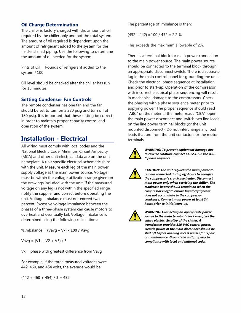
Oil Charge Determination The chiller is factory charged with the amount of oil
required by the chiller only and not the total system.
The amount of oil required is dependent upon the
amount of refrigerant added to the system for the
field-installed piping. Use the following to determine
the amount of oil needed for the system.
Pints of Oil = Pounds of refrigerant added to the
system / 100
Oil level should be checked after the chiller has run
for 15 minutes.
Setting Condenser Fan Controls The remote condenser has one fan and the fan
should be set to turn on a 220 psig and turn off at
180 psig. It is important that these setting be correct
in order to maintain proper capacity control and
operation of the system.
Installation - Electrical All wiring must comply with local codes and the
National Electric Code. Minimum Circuit Ampacity
(MCA) and other unit electrical data are on the unit
nameplate. A unit specific electrical schematic ships
with the unit. Measure each leg of the main power
supply voltage at the main power source. Voltage
must be within the voltage utilization range given on
the drawings included with the unit. If the measured
voltage on any leg is not within the specified range,
notify the supplier and correct before operating the
unit. Voltage imbalance must not exceed two
percent. Excessive voltage imbalance between the
phases of a three-phase system can cause motors to
overheat and eventually fail. Voltage imbalance is
determined using the following calculations:
%Imbalance = (Vavg – Vx) x 100 / Vavg
Vavg = (V1 + V2 + V3) / 3
Vx = phase with greatest difference from Vavg
For example, if the three measured voltages were
442, 460, and 454 volts, the average would be:
(442 + 460 + 454) / 3 = 452
The percentage of imbalance is then:
(452 – 442) x 100 / 452 = 2.2 %
This exceeds the maximum allowable of 2%.
There is a terminal block for main power connection
to the main power source. The main power source
should be connected to the terminal block through
an appropriate disconnect switch. There is a separate
lug in the main control panel for grounding the unit.
Check the electrical phase sequence at installation
and prior to start-up. Operation of the compressor
with incorrect electrical phase sequencing will result
in mechanical damage to the compressors. Check
the phasing with a phase sequence meter prior to
applying power. The proper sequence should read
“ABC” on the meter. If the meter reads “CBA”, open
the main power disconnect and switch two line leads
on the line power terminal blocks (or the unit
mounted disconnect). Do not interchange any load
leads that are from the unit contactors or the motor
terminals.
WARNING: To prevent equipment damage due
to reverse rotation, connect L1-L2-L3 in the A-B-
C phase sequence.
CAUTION: The unit requires the main power to
remain connected during off-hours to energize
the compressor’s crankcase heater. Disconnect
main power only when servicing the chiller. The
crankcase heater should remain on when the
compressor is off to ensure liquid refrigerant
does not accumulate in the compressor
crankcase. Connect main power at least 24
hours prior to initial start-up.
WARNING: Connecting an appropriate power
source to the main terminal block energizes the
entire electric circuitry of the chiller. A
transformer provides 110 VAC control power.
Electric power at the main disconnect should be
shut off before opening access panels for repair
or maintenance. Ground the unit properly in
compliance with local and national codes.

13
Table 10 - EQ Air Cooled Chiller Electrical Specifications
Model Process
Pump
(hp)
Rated
Voltage
Allowable Power Compressor Data Fan Pump Control
Power
Unit Data
Min Max RLA1 LRA
2 FLA
3 FLA
3 FLA MCA
4 MOCP
5
EQ3A01 None 230/1/60 207 253 5.2 29 1.6 0.0 0.22 8.3 9.9
¼ hp 230/1/60 207 253 5.2 29 1.6 2.4 0.22 10.7 13.3
EQ2A02
None 230/3/60 207 253 8.6 58 1.6 0.0 0.22 12.6 16.9
1 230/3/60 207 253 8.6 58 1.6 3.6 0.22 16.2 20.5
2 230/3/60 207 253 8.6 58 1.6 6.8 0.22 19.4 23.7
3 230/3/60 207 253 8.6 58 1.6 9.6 0.22 22.2 26.5
None 460/3/60 414 506 4.6 29 0.8 0.0 0.11 6.7 9.0
1 460/3/60 414 506 4.6 29 0.8 1.8 0.11 8.5 10.8
2 460/3/60 414 506 4.6 29 0.8 3.4 0.11 10.1 12.4
3 460/3/60 414 506 4.6 29 0.8 4.8 0.11 11.5 13.8
EQ2A03
None 230/3/60 207 253 14.3 93 2.9 0.0 0.22 21.0 28.1
1 230/3/60 207 253 14.3 93 2.9 3.6 0.22 24.6 31.8
2 230/3/60 207 253 14.3 93 2.9 6.8 0.22 27.8 35.0
3 230/3/60 207 253 14.3 93 2.9 9.6 0.22 30.6 37.8
None 460/3/60 414 506 6.4 48 1.5 0.0 0.11 9.6 12.8
1 460/3/60 414 506 6.4 48 1.5 1.8 0.11 11.4 14.6
2 460/3/60 414 506 6.4 48 1.5 3.4 0.11 13.0 16.2
3 460/3/60 414 506 6.4 48 1.5 4.8 0.11 14.4 17.6
Notes:
1. RLA is Rated Load Amps.
2. LRA is Locked Rotor Amps.
3. FLA is Full Load Amps.
4. MCA is Minimum Circuit Ampacity (for wire sizing) and includes compressor, condenser fans, pump, and control circuit.
5. MOCP is Maximum Overcurrent Protection.
Table 11 - EQ Water Cooled Chiller Electrical Specifications
Model Process
Pump (hp)
Rated
Voltage
Allowable Power Compressor Data Pump Control Power Unit Data
Min Max RLA1 LRA
2 FLA
3 FLA MCA
4 MOCP
5
EQ2W02
None 230/3/60 207 253 8.6 58 0.0 0.22 12.6 16.9
1 230/3/60 207 253 8.6 58 3.6 0.22 16.2 20.5
2 230/3/60 207 253 8.6 58 6.8 0.22 19.4 23.7
3 230/3/60 207 253 8.6 58 9.6 0.22 22.2 26.5
None 460/3/60 414 506 4.6 29 0.0 0.11 6.7 9.0
1 460/3/60 414 506 4.6 29 1.8 0.11 8.5 10.8
2 460/3/60 414 506 4.6 29 3.4 0.11 10.1 12.4
3 460/3/60 414 506 4.6 29 4.8 0.11 11.5 13.8
EQ2W03
& EQR03
None 230/3/60 207 253 14.3 93 0.0 0.22 21.0 28.2
1 230/3/60 207 253 14.3 93 3.6 0.22 24.6 31.8
2 230/3/60 207 253 14.3 93 6.8 0.22 27.8 35.0
3 230/3/60 207 253 14.3 93 9.6 0.22 30.6 37.8
None 460/3/60 414 506 6.4 48 0.0 0.11 9.6 12.8
1 460/3/60 414 506 6.4 48 1.8 0.11 11.4 14.6
2 460/3/60 414 506 6.4 48 3.4 0.11 13.0 16.2
3 460/3/60 414 506 6.4 48 4.8 0.11 14.4 17.6
Notes:
1. RLA is Rated Load Amps.
2. LRA is Locked Rotor Amps.
3. FLA is Full Load Amps.
4. MCA is Minimum Circuit Ampacity (for wire sizing) and includes compressor, condenser fans, pump, and control circuit.
5. MOCP is Maximum Overcurrent Protection.
14
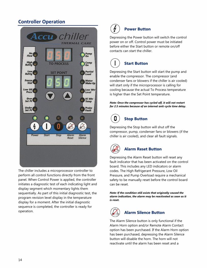
Controller Operation
The chiller includes a microprocessor controller to
perform all control functions directly from the front
panel. When Control Power is applied, the controller
initiates a diagnostic test of each indicating light and
display segment which momentary lights them
sequentially. As part of this initial diagnostic test, the
program revision level display in the temperature
display for a moment. After the initial diagnostic
sequence is completed, the controller is ready for
operation.
Power Button
Depressing the Power button will switch the control
power on or off. Control power must be initiated
before either the Start button or remote on/off
contacts can start the chiller.
Start Button
Depressing the Start button will start the pump and
enable the compressor. The compressor (and
condenser fans or blowers if the chiller is air cooled)
will start only if the microprocessor is calling for
cooling because the actual To Process temperature
is higher than the Set Point temperature.
Note: Once the compressor has cycled off, it will not restart
for 2.5 minutes because of an internal anti-cycle time delay.
Stop Button
Depressing the Stop button will shut off the
compressor, pump, condenser fans or blowers (if the
chiller is air cooled), and clear all fault signals.
Alarm Reset Button
Depressing the Alarm Reset button will reset any
fault indicator that has been activated on the control
board. This includes any LED indicators or alarm
codes. The High Refrigerant Pressure, Low Oil
Pressure, and Pump Overload require a mechanical
safety to be manually reset before the control board
can be reset.
Note: If the condition still exists that originally caused the
alarm indication, the alarm may be reactivated as soon as it
is reset.
Alarm Silence Button
The Alarm Silence button is only functional if the
Alarm Horn option and/or Remote Alarm Contact
option has been purchased. If the Alarm Horn option
has been purchased, depressing the Alarm Silence
button will disable the horn. The horn will not
reactivate until the alarm has been reset and a

15
subsequent alarm has been triggered. If the Remote
Alarm contacts option has been purchased,
depressing the Alarm Silence button will open the
contact that was closed when the alarm occurred.
The contact will not close again until the alarm has
been reset and a subsequent alarm has been
triggered.
Lower Set Point Temperature
Button
Each time the Lower Set Point Temperature button is
depressed and released the Set Point temperature
will decreased by 1°. If the Lower Set Point
Temperature button is held down, the Set Point
temperature will continue to decrease until the
button is released.
Raise Set Point Temperature
Button
Each time the Raise Set Point Temperature button is
depressed and released the Set Point temperature
will increased by 1°. If the Raise Set Point
Temperature button is held down, the Set Point
temperature will continue to increase until the
button is released.
No Flow LED
The No Flow LED will be illuminated if the flow
through the chiller is interupted. The pressure or
flow switch communicates to the controller the
status of coolant flow. When the Start button is
depressed, this safety is defeated for a period of 20
seconds in order for the pump to establish flow. The
No Flow LED may remain illuminated during this 20
second period. This safety will shut off the pump and
the compressor. If the chiller has been shut down by
the No Flow safety, the Start button must be
depressed in order to restart the pump and reset the
20 second time delay.
High Refrigeration Pressure LED
If the compressor discharge refrigerant pressure
exceeds the setting on the high refrigerant pressure
safety, the compressor and pump will shut off and
the High Refrigerant Pressure LED will be
illuminated. Pressing the Alarm Reset button will
reset the High Refrigerant Pressure fault, as long as
the High Refrigerant Pressure switch located at the
discharge of the compressor has been manually
reset.
Low Refrigeration Pressure LED
If the compressor suction pressure drops below the
setting on the low refrigerant pressure safety, the
compressor will shut off, the pump will remain
running, and the Low Refrigerant Pressure LED will
be illuminated. Pressing the Alarm Reset button will
reset the Low Refrigerant Pressure fault, as long as
the refrigerant pressure has risen back up above the
safety's cutout level.
Freezestat LED
If the coolant temperature being delivered to the
process drops below the setting on the Freezestat,
the compressor will shut off, the pump will remain
running, and the Freezestat LED will be illuminated.
The Freezestat should be set 10°F above the freezing
point of the glycol solution and 10°F below the
minimum operating temperature. The Freezestat is
factory set at 38°F. In order to reset the Freezestat
fault press the Alarm Reset button on front control
interface.
Low Oil Pressure LED
This LED is nonfunctional on standard units and will
be activated only if the unit has been modified to
include a low oil pressure sensor (typical for semi-
hermetic reciprocating compressor units). If the unit
has a low oil pressure sensor and the oil pressure in
the compressor crankcase drops below the factory
set level on the oil pressure switch, the compressor
and pump will shut off, and the Low Oil Pressure LED
will be illuminated. In order to reset the Low Oil
Pressure fault, press the Alarm Reset button after
resetting the mechanical pressure switch located
inside of the cabinet near the compressor.

16
Over Set Point LED
The Over Set Point LED will be illuminated if the To
Process temperature exceeds the Set Point
temperature by more than 5°F. This fault causes only
an alarm indication (horn and/or remote contact)
and the chiller will continue to operate. Although the
Over Set Point LED will turn on immediately
whenever the temperature is out of range, the alarm
relay is disabled for 30 minutes after start-up or after
a change in set point. The alarm will automatically
clear when the To Process temperature is no more
that 5°F above the Set Point temperature.
Under Set Point LED
The Under Set Point LED will be illuminated if the To
Process temperature drops below the Set Point
temperature by more than 10°F. This fault will shut
off the compressor, but the pump will continue to
run. Although the Under Set Point LED will turn on
immediately whenever the temperature is out of
range, the alarm relay is disabled for 30 minutes
after start-up or after a change in set point. Pressing
the Alarm Reset button will reset this fault.
Pump On LED
The Pump On LED will be illuminated whenever the
pump is running. If the pump is shut off due to a
safety, the Pump On LED will turn off. The Start
button must be pressed in order to restart the pump.
Compressor On LED
The Compressor On LED will be illuminated
whenever the compressor is running. The
Compressor On LED will cycle on and off with the
compressor. The compressor will not come on unless
the pump is already running and the To Process
temperature is above the Set Point temperature.
Note: During normal operation, the compressor may cycle on
and off. An internal anti-cycle time delay will not allow the
compressor to restart for 2.5 minutes after it has cycled off.
For air cooled units the fans will cycle off with the compressor.
Part Load LED
The Partial Load LED will be illuminated whenever
the microprocessor energizes the hot gas bypass
solenoid valve. This valve is cycled in order for the
chiller to maintain a constant To Process
temperature even when there is only a partial load.
The longer that this LED stays on, the more unused
excess capacity is available from the chiller. If the
Partial Load LED stays off, the chiller is fully loaded
by the heat from the process. If the Partial Load LED
stays on, the chiller has a very small load on it from
the process. If this low load condition persists, the To
Process temperature may begin to drop below the
Set Point temperature, and when it reaches 7°F
below the Set Point temperature, the compressor
will cycle off. The compressor will come back on
when the To Process temperature rises back up to
the Set Point temperature and the anti-cycle 2.5
minute time delay relay has timed out.
Water Make-Up LED
This LED is nonfunctional on standard units and will
be active only if the Water Make-Up option has been
purchased. When the water level in the reservoir
drops below the lower limit of the float switch, the
water make-up solenoid valve is opened and the
Water Make-Up LED is illuminated. When the water
level rises to the upper limit of the float switch, the
water make-up solenoid is closed and the Water
Make-Up LED turns off. The microprocessor will also
close the water make-up solenoid valve if it has been
open for 10 minutes. This is done to help prevent
further problems if a water leak has developed in the
system. If this occurs, the Water Make-Up LED turns
off and the Low Water Level LED remains
illuminated.
Low Water Level LED
This LED is nonfunctional on standard units and will
only be active if the Low Water Level option or the
Water Make-Up option has been purchased. When
the water level in the reservoir drops below the
lower limit of the float switch, the Low Water Level
LED is illuminated. When the water level rises to the
upper limit of the float switch, the Low Water Level
LED will shut off.

17
High Water Temperature LED
The High Water Temperature LED will be illuminated
if the To Process temperature rises more than 10°F
above the Set Point temperature. The High Water
Temperature LED will turn off when the water
temperature is less than 10°F above the Set Point
temperature. This fault will not stop operation of the
chiller.
Probe Fault LED
The Probe Fault LED will illuminate if the signal from
the thermocouple is out of tolerance. This fault will
also shut off the compressor and the pump. Pressing
the Alarm Reset button will reset this alarm.
Changing Temperature Display Scale The chiller is able to display temperatures in either °F
or °C. To determine which temperature is in use and
to change the temperature scale use stop the unit
and press the Power button to turn off the
controller. Press and hold the Stop Button and then
press the Power Button. When the controller
illuminates, release both buttons. The To Process
display will read "Unt". The Set Point display will
show either "F" or "C" depending on the current
display units selected. If "F" is displayed the
temperature display is in °F mode. If "C" is displayed
the temperature display is in °C mode. To change
from °F to °C press the Lower Set Point Temperature
button. To change from °C to °F press the Raise Set
Point Temperature button. After changing to the
desired temperature scale the Set Point display show
the desired display units. Press and release the Start
button to store the new selection into the controller
memory then press and release the Power button to
exit the function. Press and release the Power button
again to restore controller power. The unit is now
ready for operation.
Table 12 - Microprocessor Control Fault Logic
Fault Alarm
Indication
Compressor
Shutdown
Pump
Shut Off
Alarm
Reset
Required1
Manual
Reset
Required2
Remote
Alarm
Activated3
No Flow LED Yes Yes No No Yes
High Refrigerant Pressure LED Yes Yes Yes Yes Yes
Low Refrigerant Pressure LED Yes No Yes No Yes
Freezestat LED Yes No Yes No Yes
Low Oil Pressure LED Yes Yes Yes Yes Yes
Over Set Point LED No No No No Yes
Under Set Point LED Yes No Yes No Yes
Low Water Level LED No No No No No
High Water Temperature LED No No No No No
Probe Fault LED Yes Yes Yes No Yes
Low Power Pr OFF Yes Yes Yes No Yes
Pump Overload Err 126 Yes Yes Yes Yes Yes
Compressor Overload Err 127 Yes Yes Yes No Yes
High Temperature Safety Err 128 Yes Yes Yes No Yes 1 Alarm Reset button or Stop button on control panel must be pressed.
2 Safety control must be manually reset before the controller can be reset.
3 Activates the alarm horn (if included) and closes the alarm contact (if included).

18
Diagnostic Error Codes Several different error codes may be displayed on the digital readouts labeled To Process and Set Point. Most of
the possible error codes indicate some type of failure in the microprocessor controller. Table 13 shows a list of the
error codes. If there are any error codes other than the one listed below, try to reset the unit by shutting the
power off and then turning it back on. If this does not work, make a note of the error code and contact our
Customer Service Department for further assistance.
Table 13 - Diagnostic Error Codes
Error
Code Description Cause/Corrective Action
Pr Off Brown Out Indication
Indicates the chiller is running and main power is discontinued or drops more than
10% below the normal operating voltage, the unit will shut down and the Pr OFF
fault will be indicated on the digital displays. Pressing the Power button will clear
this fault condition.
101 EEPROM Failure Controller requires servicing. Contact Manufacturer for repair or replacement.
102 A/D Converter Failure Controller requires servicing. Contact Manufacturer for repair or replacement.
103 Controller serial bus failure Controller requires servicing. Contact Manufacturer for repair or replacement.
105 CJC Error Controller requires servicing. Contact Manufacturer for repair or replacement.
109 Unused memory byte changed Controller requires servicing. Contact Manufacturer for repair or replacement.
110 Device or communication
configuration change or invalid Controller requires servicing. Contact Manufacturer for repair or replacement.
111 Fixed parameter associated
with range invalid Controller requires servicing. Contact Manufacturer for repair or replacement.
112 Setpoint out of temperature
range Controller requires servicing. Contact Manufacturer for repair or replacement.
113 RAM hardware failure Controller requires servicing. Contact Manufacturer for repair or replacement.
114 Invalid device configuration Controller requires servicing. Contact Manufacturer for repair or replacement.
117 Invalid program counter Controller requires servicing. Contact Manufacturer for repair or replacement.
118 Infinite software loop detect Controller requires servicing. Contact Manufacturer for repair or replacement.
119 Data direction register failure Controller requires servicing. Contact Manufacturer for repair or replacement.
120 Communication data register
failure Controller requires servicing. Contact Manufacturer for repair or replacement.
121 Timer data register failure Controller requires servicing. Contact Manufacturer for repair or replacement.
122 Hardware watchdog data
register failure Controller requires servicing. Contact Manufacturer for repair or replacement.
123 Option data register failure Controller requires servicing. Contact Manufacturer for repair or replacement.
125 Jumper for temperature
controller missing Indicates the jumper is loose or missing on the control circuit board.
126 Pump overload on chiller
Indicates the pump overload has tripped. In order to reset this fault; press the
Alarm Reset button after resetting the pump overload inside the electrical
enclosure.
19
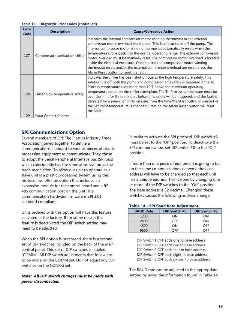
Table 13 – Diagnostic Error Codes (continued)
Error
Code Description Cause/Corrective Action
127 Compressor overload on chiller
Indicates the internal compressor motor winding thermostat or the external
compressor motor overload has tripped. This fault also shuts off the pump. The
internal compressor motor winding thermostat automatically resets when the
temperature drops back into the normal operating range. The external compressor
motor overload must be manually reset. The compressor motor overload is located
inside the electrical enclosure. Once the internal compressor motor winding
thermostat resets and/or the external compressor overload are reset, press the
Alarm Reset button to reset the fault.
128 Chiller high temperature safety
Indicates the chiller has been shut off due to the high temperature safety. This
safety shuts off both the pump and compressor. This safety is triggered if the To
Process temperature rises more than 10°F above the maximum operating
temperature noted on the chiller nameplate. The To Process temperature must be
over the limit for three minutes before this safety will be triggered, and the fault is
defeated for a period of thirty minutes from the time the Start button is pressed or
the Set Point temperature is changed. Pressing the Alarm Reset button will reset
this fault.
129 Input Contact Chatter
SPI Communications Option Several members of SPI: The Plastics Industry Trade
Association joined together to define a
communications standard to various pieces of plastic
processing equipment to communicate. They chose
to adopt the Serial Peripheral Interface bus (SPI bus)
which coincidently has the same abbreviation as the
trade association. To allow our unit to operate as a
slave unit is a plastic processing system using this
protocol, we offer an option that includes an
expansion module for the control board and a RS-
485 communication port on the unit. The
communication hardware firmware is SPI 3.01
standard compliant.
Units ordered with this option will have this feature
activated at the factory. If for some reason this
feature is deactivated the DIP switch setting may
need to be adjusted.
When the SPI option is purchased, there is a second
set of DIP switches included on the back of the main
control panel. This set of DIP switches is labeled
"COMM". All DIP switch adjustments that follow are
to be made on the COMM set. Do not adjust any DIP
switches on the CONFIG set.
Note: All DIP switch changes must be made with
power disconnected.
In order to activate the SPI protocol, DIP switch #8
must be set to the "On" position. To deactivate the
SPI communication, set DIP switch #8 to the "Off"
position.
If more than one piece of equipment is going to be
on the same communications network, the base
address will have to be changed so that each unit
has a unique address. This is done by changing one
or more of the DIP switches to the "Off" position.
The base address is 32 decimal. Changing these
switches causes the following address change.
Table 14 - SPI Baud Rate Adjustment
BAUD Rate DIP Switch #6 DIP Switch #7
1200 ON ON
2400 OFF ON
4800 ON OFF
9600 OFF OFF
DIP Switch 1 OFF adds one to base address
DIP Switch 2 OFF adds two to base address
DIP Switch 3 OFF adds four to base address
DIP Switch 4 OFF adds eight to base address
DIP Switch 5 OFF adds sixteen to base address
The BAUD rate can be adjusted to the appropriate
setting by using the information found in Table 14.
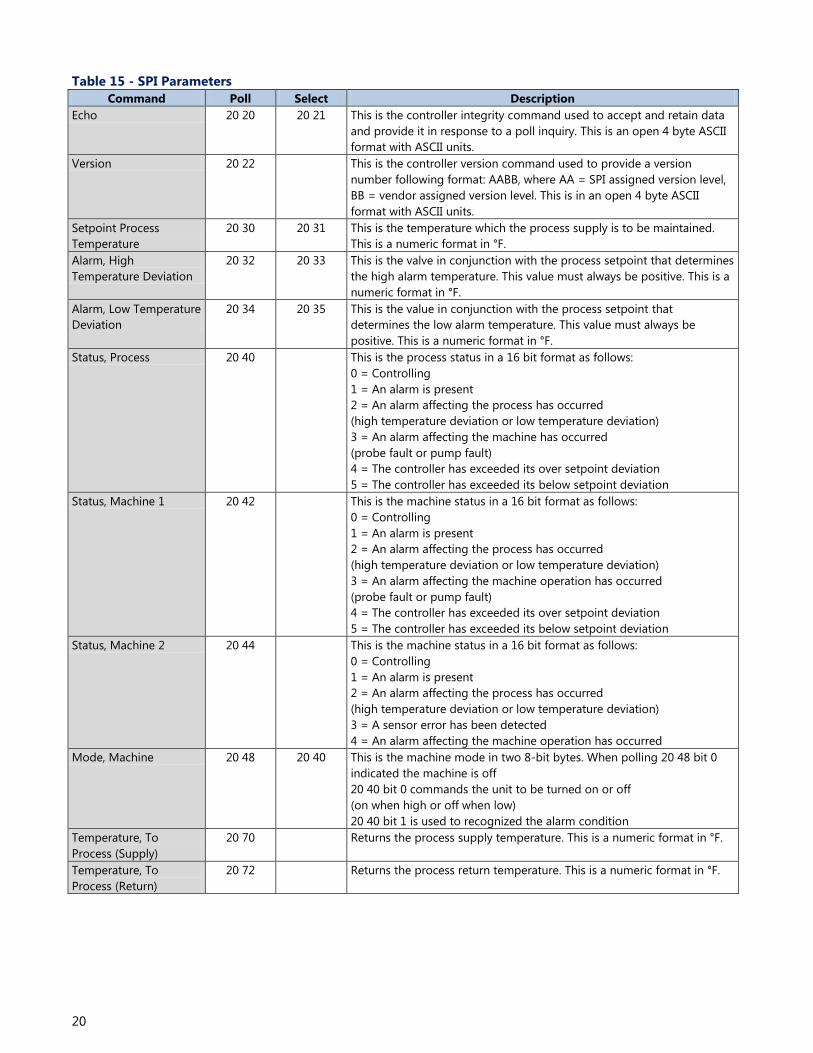
20
Table 15 - SPI Parameters
Command Poll Select Description
Echo 20 20 20 21 This is the controller integrity command used to accept and retain data
and provide it in response to a poll inquiry. This is an open 4 byte ASCII
format with ASCII units.
Version 20 22 This is the controller version command used to provide a version
number following format: AABB, where AA = SPI assigned version level,
BB = vendor assigned version level. This is in an open 4 byte ASCII
format with ASCII units.
Setpoint Process
Temperature
20 30 20 31 This is the temperature which the process supply is to be maintained.
This is a numeric format in °F.
Alarm, High
Temperature Deviation
20 32 20 33 This is the valve in conjunction with the process setpoint that determines
the high alarm temperature. This value must always be positive. This is a
numeric format in °F.
Alarm, Low Temperature
Deviation
20 34 20 35 This is the value in conjunction with the process setpoint that
determines the low alarm temperature. This value must always be
positive. This is a numeric format in °F.
Status, Process 20 40 This is the process status in a 16 bit format as follows:
0 = Controlling
1 = An alarm is present
2 = An alarm affecting the process has occurred
(high temperature deviation or low temperature deviation)
3 = An alarm affecting the machine has occurred
(probe fault or pump fault)
4 = The controller has exceeded its over setpoint deviation
5 = The controller has exceeded its below setpoint deviation
Status, Machine 1 20 42 This is the machine status in a 16 bit format as follows:
0 = Controlling
1 = An alarm is present
2 = An alarm affecting the process has occurred
(high temperature deviation or low temperature deviation)
3 = An alarm affecting the machine operation has occurred
(probe fault or pump fault)
4 = The controller has exceeded its over setpoint deviation
5 = The controller has exceeded its below setpoint deviation
Status, Machine 2 20 44 This is the machine status in a 16 bit format as follows:
0 = Controlling
1 = An alarm is present
2 = An alarm affecting the process has occurred
(high temperature deviation or low temperature deviation)
3 = A sensor error has been detected
4 = An alarm affecting the machine operation has occurred
Mode, Machine 20 48 20 40 This is the machine mode in two 8-bit bytes. When polling 20 48 bit 0
indicated the machine is off
20 40 bit 0 commands the unit to be turned on or off
(on when high or off when low)
20 40 bit 1 is used to recognized the alarm condition
Temperature, To
Process (Supply)
20 70 Returns the process supply temperature. This is a numeric format in °F.
Temperature, To
Process (Return)
20 72 Returns the process return temperature. This is a numeric format in °F.

21
Return Temperature Display Option This option allows the To Process digital display to
indicate To Process or Return Water Temperatures.
To view the Return Water Temperature, hold down
the Lower Set Point Temperature and Raise Set Point
Temperature buttons simultaneously. Once the
buttons are released, the display will return to the To
Process temperature.
Remote On/Off Contacts Option This option allows the unit to be turned on and off
via a remote contact closure. Two terminals are
provided in the control panel to be wired to a
remote contact closure device. Switching the
contacts from open to closed simulates pressing the
Start button on the control panel. Switching the
contacts from closed to open simulates pressing the
Stop button. Please note that the Remote On/Off
contacts are nonfunctional until the Power button
has been depressed and the control circuit has been
energized. This option also includes a remote/local
toggle switch that allows the operator to disable the
remote contacts for safety purposes while the unit is
being serviced. Note: Do not introduce any
external voltage to these contacts as this will
result in damage to the microprocessor, which
will not be covered by the warranty.
Remote Alarm Contacts Option This option includes a set of dry (no voltage induced
by chiller), normally open contacts that will close
when there is an alarm condition. Refer to Table 12
to determine which faults will trigger the Remote
Alarm contacts. The contacts will reopen by clearing
the fault or by pressing the Alarm Silence button.
Alarm Horn Option This option includes an alarm horn that will be
activated by certain faults. Refer to Table 12Table 12
to determine which faults will trigger the Alarm
Horn. The Alarm Horn will be silenced by clearing
the fault or by pressing the Alarm Silence button. If
this option is selected in conjunction with the
remote control panel, the Alarm Horn will be
mounted on the chiller and not the remote control
panel.
Remote Hand-Held Control Option This option removes the display and control buttons
from the chiller and places them in a small hand-
held enclosure. Included with this option is a 50 foot
cable to connect the controller and the chiller. All
control functions are available to the operator at the
location of the remote panel and no control
functions are available at the location of the chiller.
Safety Guidelines Observe all safety precautions during installation,
start-up, and service of this equipment due to the
presence of high voltage and refrigerant charge.
Only qualified personnel should install, start-up, and
service this equipment.
When working on this equipment, observe
precautions in literature, and on tags, stickers, and
labels located on the equipment. Wear work gloves
and safety glasses.
WARNING: This equipment contains hazardous
voltages that can cause severe injury or death.
Disconnect and lock out incoming power before
installing or servicing the equipment.
WARNING: This equipment contains refrigerant
under pressure. Accidental release of refrigerant
under pressure can cause personal injury and or
property damage. Exercise care while working
on or around this equipment.
WARNING: Vent all refrigerant relief valves in
accordance to ANSI/ASHRAE Standard 15,
Safety Code for Mechanical Refrigeration. This
equipment should be located within a well-
ventilated area. Inhalation of refrigerant can be
hazardous to your health and the accumulation
of refrigerant within an enclosed space can
displace oxygen and cause suffocation.
Start-Up Every unit is factory set to deliver chilled water in
accordance with the standard operating
specifications for that particular chiller. Due to
variables involved with different applications and
different installations, minor adjustments may be
required during the initial start-up to ensure proper
operation.
We strongly recommend the following start-up
procedure be performed by a qualified experienced
refrigeration technician and must be followed in
sequence. If trouble is encountered the fault can
usually be traced to one of the control or safety
devices. This outline serves as a checklist for the

22
initial start-up and for subsequent start-ups if the
chiller is out of service for a prolonged time.
Connect Main Power Connect main power properly ensuring it matches
the voltage shown on the nameplate of the unit.
Check the electrical phase sequence prior to start-
up. Operation of the compressor with incorrect
electrical phase sequencing will result in mechanical
damage to the compressors. Check the phasing with
a phase sequence meter prior to applying power.
The proper sequence should read “ABC” on the
meter. If the meter reads “CBA”, open the main
power disconnect and switch two line leads on the
line power terminal blocks (or the unit mounted
disconnect). All components requiring electric power
are in-phase at the factory. Do not interchange any
load leads that are from the unit contactors or the
motor terminals. After making proper power
connection and grounding, turn the main power on.
WARNING: To prevent equipment damage due
to reverse rotation, connect L1-L2-L3 in the A-B-
C phase sequence.
CAUTION: The unit requires the main power to
remain connected during off-hours to energize
the compressor’s crankcase heater. Disconnect
main power only when servicing the chiller. The
crankcase heater should remain on when the
compressor is off to ensure liquid refrigerant
does not accumulate in the compressor
crankcase.
WARNING: Connecting an appropriate power
source to the main terminal block energizes the
entire electric circuitry of the chiller. A
transformer provides 120 VAC control power.
Electric power at the main disconnect should be
shut off before opening access panels for repair
or maintenance. Ground the unit properly in
compliance with local and national codes.
Fill Coolant Circuit Check to make sure all process chilled-water piping
connections are secure. Open the chiller cabinet and
fill the coolant reservoir with the proper water or
water/glycol solution following the guidelines of the
system fill water chemistry as shown below and in
Table 16Table 16. When using a glycol solution only
use glycol with a corrosion inhibitor. See Table 17 for
recommended glycol solutions.
System Fill Water Chemistry Requirements
Water is a unique molecule whose properties make it
ideal for heat transfer applications. It is safe: non-
flammable and non-poisonous. It is easy to handle,
widely available and inexpensive in most
industrialized areas. It is capable of absorbing more
heat per unit mass than almost any other material.
Water also has properties that need to be within
limits to avoid unwanted side effects. Water is a
“universal solvent” because it can dissolve many
solid substances to some extent and absorb gasses.
As a result, water can cause the corrosion of metals
used in a cooling system. Often water is in an open
system (exposed to air) that concentrates the ions as
water evaporates as in a cooling tower. As the
concentration exceeds the solubility of some
minerals, scale forms. The life giving properties of
water can also encourage biological growth that can
foul heat transfer surfaces.
Sometimes the source of the water can be the cause
of some of the problems. Anyone living in an area
with extremely hard water that has caused scale
build up can attest to that. Source waters available
for make-up use have an almost unlimited chemistry
variation.
To avoid the unwanted side effects associated with
water cooling, proper chemical treatment and
preventive maintenance is required for continuous
plant productivity.
Unwanted Side Effects of Improper Water Quality
• Corrosion
• Scale
• Fouling
• Biological Contamination

23
Cooling Water Chemistry Properties
• Electrical Conductivity
• pH
• Alkalinity
• Total Hardness
• Dissolved gases
Some of the water chemistry properties can combine
to cause the unwanted side effects. Some of the
levels are temperature dependant (i.e. dissolved
gases).
Our chiller construction minimizes the potential for
corrosion by using stainless steel brazed plate heat
exchangers. The stainless steel resists corrosion but
is not immune to it. These, as all heat exchangers,
are susceptible to fouling that may coat the heat
transfer surfaces. Coating of these surfaces reduces
the heat transfer surface, increases the fluid
velocities and pressure drops through the heat
exchanger. All of these effects reduce the heat
transfer and affect the productivity of the plant. This
is just as true with shell and tube heat exchangers.
Chilled cooling water systems, at their simplest, have
two main heat exchangers: one that absorbs the heat
from the process and the evaporator of the chiller
that removes the heat from the system. The chiller is
only part of the entire cooling system. The system
requires proper design following sound engineering
practice and satisfying local and industry standards.
Improperly designed or installed systems may cause
unsatisfactory operation and/or system failure.
The complex nature of water chemistry requires a
specialist to evaluate and implement appropriate
sensing, measurement and treatment needed for
satisfactory performance and life. The
recommendations of the specialist may include
filtration, monitoring, treatment and control devices.
With the ever-changing regulations on water usage
and treatment chemicals, the information is always
up to date when a specialist in the industry is
involved. Table 16 shows the list of water
characteristics and quality limitations.
Table 16 – Fill Water Chemistry Requirements
Water Characeristic Quality Limitation
Alkalinity (HCO3-) 70-300 ppm
Aluminum (Al) Less than 0.2 ppm
Ammonium (NH3) Less than 2 ppm
Chlorides (Cl-) Less than 300 ppm
Electrical Conductivity 10-500µS/cm
Free (aggressive) Carbon
Dioxide (CO2)† Less than 5 ppm
Free Chlorine(Cl2) Less than 1 PPM
HCO3-/SO4
2- Greater than 1.0
Hydrogen Sulfide (H2S)* Less than 0.05 ppm
Iron (Fe) Less than 0.2 ppm
Manganese (Mn) Less than 0.1 ppm
Nitrate (NO3) Less than 100 ppm
pH 7.5-9.0
Sulfate (SO42-
) Less than 70 ppm
Total Hardness (dH)k 4.0-8.5
* Sulfides in the water quickly oxidize when exposed
to air, requiring that no agitation occur when taking
a water sample. Unless tested immediately at the
site, the sample will require stabilization with a few
drops of one Molar zinc acetate solution, allowing
accurate sulfide determination up to 24 hours after
sampling. A low pH and high alkalinity cause system
problems, even when both values are within the
range shown. The term pH refers to the acidity,
basicity, or neutrality of the water supply. Below 7.0,
water is considered to be acidic. Neutral water
contains a pH of 7.0.
† Dissolved carbon dioxide calculation is from the pH
and total alkalinity values shown below or measured
on the site using a test kit.
Dissolved Carbon Dioxide, PPM = TA x 2[(6.3-pH)/0.3]
where TA = Total Alkalinity, PPM as CaCO3
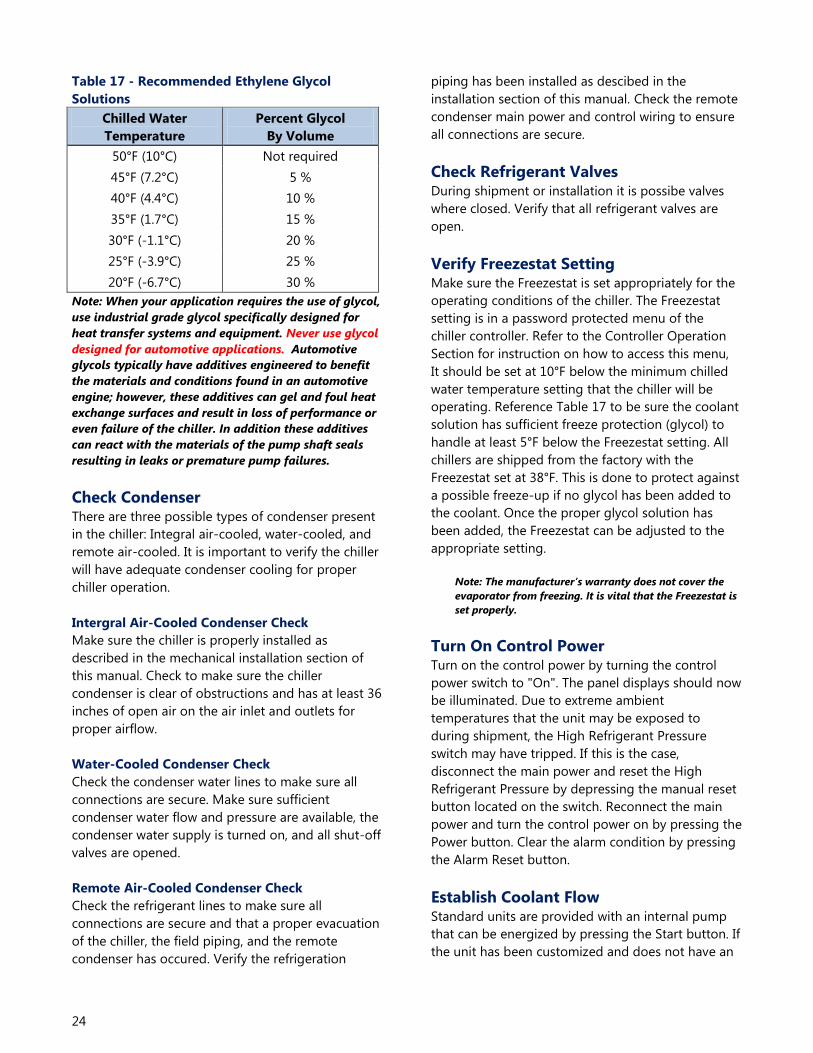
24
Table 17 - Recommended Ethylene Glycol
Solutions
Chilled Water
Temperature
Percent Glycol
By Volume
50°F (10°C) Not required
45°F (7.2°C) 5 %
40°F (4.4°C) 10 %
35°F (1.7°C) 15 %
30°F (-1.1°C) 20 %
25°F (-3.9°C) 25 %
20°F (-6.7°C) 30 %
Note: When your application requires the use of glycol,
use industrial grade glycol specifically designed for
heat transfer systems and equipment. Never use glycol
designed for automotive applications. Automotive
glycols typically have additives engineered to benefit
the materials and conditions found in an automotive
engine; however, these additives can gel and foul heat
exchange surfaces and result in loss of performance or
even failure of the chiller. In addition these additives
can react with the materials of the pump shaft seals
resulting in leaks or premature pump failures.
Check Condenser There are three possible types of condenser present
in the chiller: Integral air-cooled, water-cooled, and
remote air-cooled. It is important to verify the chiller
will have adequate condenser cooling for proper
chiller operation.
Intergral Air-Cooled Condenser Check
Make sure the chiller is properly installed as
described in the mechanical installation section of
this manual. Check to make sure the chiller
condenser is clear of obstructions and has at least 36
inches of open air on the air inlet and outlets for
proper airflow.
Water-Cooled Condenser Check
Check the condenser water lines to make sure all
connections are secure. Make sure sufficient
condenser water flow and pressure are available, the
condenser water supply is turned on, and all shut-off
valves are opened.
Remote Air-Cooled Condenser Check
Check the refrigerant lines to make sure all
connections are secure and that a proper evacuation
of the chiller, the field piping, and the remote
condenser has occured. Verify the refrigeration
piping has been installed as descibed in the
installation section of this manual. Check the remote
condenser main power and control wiring to ensure
all connections are secure.
Check Refrigerant Valves During shipment or installation it is possibe valves
where closed. Verify that all refrigerant valves are
open.
Verify Freezestat Setting Make sure the Freezestat is set appropriately for the
operating conditions of the chiller. The Freezestat
setting is in a password protected menu of the
chiller controller. Refer to the Controller Operation
Section for instruction on how to access this menu,
It should be set at 10°F below the minimum chilled
water temperature setting that the chiller will be
operating. Reference Table 17 to be sure the coolant
solution has sufficient freeze protection (glycol) to
handle at least 5°F below the Freezestat setting. All
chillers are shipped from the factory with the
Freezestat set at 38°F. This is done to protect against
a possible freeze-up if no glycol has been added to
the coolant. Once the proper glycol solution has
been added, the Freezestat can be adjusted to the
appropriate setting.
Note: The manufacturer’s warranty does not cover the
evaporator from freezing. It is vital that the Freezestat is
set properly.
Turn On Control Power Turn on the control power by turning the control
power switch to "On". The panel displays should now
be illuminated. Due to extreme ambient
temperatures that the unit may be exposed to
during shipment, the High Refrigerant Pressure
switch may have tripped. If this is the case,
disconnect the main power and reset the High
Refrigerant Pressure by depressing the manual reset
button located on the switch. Reconnect the main
power and turn the control power on by pressing the
Power button. Clear the alarm condition by pressing
the Alarm Reset button.
Establish Coolant Flow Standard units are provided with an internal pump
that can be energized by pressing the Start button. If
the unit has been customized and does not have an

25
internal pump, the external pump should be
energized to establish flow through the chiller.
Note: The compressor will not start as long as the flow
switch is open. A positive flow must be established
through the evaporator before the compressor can
operate.
Set water flow using a discharge throttling valve or
flow control valve (by others). The valve should be
the same size as the To Process connection of the
chiller. Standard chillers are designed for
approximately 2.4 gpm/ton of nominal capacity. A
significant increase in flow beyond this in a standard
chiller may result in excessive pressure loss and
negatively impact chiller efficiency and in extreme
cases may cause premature wear or damage of
internal components.
Intial Unit Operation Entering the desired leaving fuid temperature on the
control panel. Unless otherwise specified, the chiller
is factory set to deliver coolant at 50°F. Adjust to the
desired operating temperature. The chiller should
now be controlling to the selected temperature.
Please note that if there is insufficient load the
compressor may cycle on and off causing swings in
temperature.
WARNING: Under no circumstance should the
High Refrigerant Pressure or the Low
Compressor Pressure switch be deactivated.
Failure to heed this warning can cause serious
compressor damage, severe personal injury or
death.
Operate the system for approximately 30 minutes.
Check the liquid line sight glass. The refrigerant flow
past the sight glass should be clear. Bubbles in the
refrigerant indicate either low refrigerant charge or
excessive pressure drop in the liquid line. A shortage
of refrigerant is indicated if operating pressures are
low and subcooling is low. Normal subcooling
ranges are from 10°F to 20°F. If subcooling is not
within this range, check the superheat and adjust if
required. The superheat should be approximately
10°F. Since the unit is factory charged, adding or
removing refrigerant charge should not be
necessary. If the operating pressures, sight glass,
superheat, and subcooling readings indicate a
refrigerant shortage, charge refrigerant as required.
With the unit running, add refrigerant vapor by
connecting the charging line to the suction service
valve and charging through the backseat port until
operating conditions become normal.
CAUTION: A clear sight glass alone does not
mean that the system is properly charged. Also
check system superheat, subcooling, and unit
operating pressures. If both suction and
discharge pressures are low but subcooling is
normal, a problem other than refrigerant
shortage exists. Do not add refrigerant, as this
may result in overcharging the circuit.
Once proper flow and temperature are achieved,
press the Stop button. The unit is now ready to be
placed into service.
Preventive Maintenance Once your portable chiller has been placed into
service, the following maintenance procedures
should be adhered to as closely as possible. The
importance of a properly established preventive
maintenance program cannot be overemphasized.
Taking the time to follow these simple procedures
will result in substantially reduced downtime,
reduced repair costs, and an extended useful lifetime
for the chiller. Any monetary costs of implementing
these procedures will almost always more than pay
for it.
To make this as simple as possible, a checklist should
be prepared which lists the recommended service
operations and the times at which they are to be
performed. At the end of this section we have
included a checklist that can be used for this
purpose. Notice that there are locations for voltage
readings, amperages, etc. so that they can be
monitored over time. With this information,
maintenance personnel may be able to correct a
potential problem before it causes any downtime.
For best results, these readings should be taken with
a full heat load from process, preferably with similar
operating conditions each time. The following is a
list of suggested periodic maintenance.
Once a Week 1. (Air-Cooled Units Only) Check the surface of the
air-cooled condenser coil for dirt and debris. To
clean, rinse thoroughly with water. Mild
detergent can be used to remove smoke and or
grease stains.
2. Check to make sure that the To Process
temperature is maintained reasonably close to

26
the Set Point temperature. If the temperature
stays more than 5°F away from the set point,
there may be a problem with the chiller. If this is
the case, refer to the Troubleshooting Chart or
contact the Customer Service Department.
3. Check the pump discharge pressure on the
gauge on the back panel of the chiller.
Investigate further if the pressure starts to stray
away from the normal operating pressure.
4. Check the coolant level in the reservoir.
Replenish if necessary making sure to take
proper precautions to maintain the appropriate
glycol concentration.
5. Check coolant circulation pump for leaks in the
seal area. Replace pump seal if necessary.
6. Check refrigerant sight glass for air bubbles or
moisture indication. If the sight glass indicates
that there is a refrigeration problem, have the
unit serviced as soon as possible.
Once a Month 7. With the main disconnect shut off and locked
out, check the condition of electrical connections
at all contactors, starters and controls. Check for
loose or frayed wires.
8. Check the incoming voltage to make sure it is
within 10% of the design voltage for the chiller.
9. Check the amp draws to each leg of the
compressor (fans or blowers on air-cooled units)
and pump to confirm that they are drawing the
proper current.
Every Three Months 10. Units are equipped with a Y-strainer between
the return connection and the evaporator inlet.
The strainer basket should be removed and
cleaned if necessary. This may be required more
often if contaminants can easily get into the
process water.
11. Have a qualified refrigeration technician inspect
the operation of the entire unit to ensure that
everything is operating properly. Have
condenser cleaned out if necessary.

27
Preventive Maintenance Checklist Model # ___________________________
Serial # ___________________________
Maintenance Activity Week Number
1 2 3 4 5 6 7 8 9 10 11 12 13
Date
Clean Condenser Coil and
Inlet Filter (air cooled units)
Temperature Control
Pump Discharge Pressure
Coolant Level
Glycol Concentration
Pump Seal
Refrigerant Sight Glass
Electrical Connections
Incoming Voltage
Compressor L1 Amps
Compressor L2 Amps
Compressor L3 Amps
Pump L1 Amps
Pump L2 Amps
Pump L3 Amps
Fan L1 Amps
Fan L2 Amps
Fan L3 Amps
Clean Y-Strainer
Refrigerant Circuit Check
Refrigerant Suction Pressure
Refrigerant Discharge Pressure
Refrigerant Superheat

28
Troubleshooting
Problem Possible Cause Remedy
Compressor will not start
Compressor overload Check supply voltage, start components (single
phase), and wiring
Run capacitor
(single phase units only) Measure capacitance and replace if faulty
Start capacitor
(single phase units only) Measure capacitance and replace if faulty
Start relay
(single phase units only)
Check for contiuity between 2,5 and 1,2. Replace if
no continuity
Compressor contactor Replace if faulty
Microprocessor control board Replace if faulty
Compressor failure Contact Customer Service Department for
assistance
Pump will not start
Pump overload Check supply voltage, wiring, overload set point
(external overload)
Pump contactor Replace if faulty
Microprocessor control board Replace if faulty
Pump motor failure Check motor windings and replace if faulty
Low refrigerant pressure
Low refrigerant charge Contact refrigeration service technician
Refrigerant leak Contact refrigeration service technician
Low refrigeration pressure sensor Check for proper range, replace if faulty
Microprocessor control board Replace if faulty
High refrigerant pressure
Dirty air filters
(air cooled units only) Clean filters
Air flow obstruction
(air cooled units only)
Make sure chiller is installed in accordance with
recommendations in this manual
High ambient air temperature
(air cooled units only)
Ambient temperature must be reduced below
105°F (40.5°C)
Condenser fan motor
(air cooled units only)
Check start compents and motor windings for
failure and replace if faulty
Condenser fan cycling control
(air cooled units only) Confirm proper operation, replace if faulty
Plugged condenser
(water cooled units only) Clean out tubes
Insufficient condenser water flow
(water cooled units only)
Make sure chiller is installed in accordance with
the recommendations of this manual
High condenser water temperature
(water cooled units only)
Condenser water temperature must be reduced
below 90°F (38°C)
Condenser water regulating valve Check setting, replace if faulty
Refrigerant circuit overcharged Contact refrigeration service technician
High refrigerant pressure sensor Replace if faulty
Microprocessor control board Replace if faulty

29
Troubleshooting (continued) Problem Possible Cause Remedy
Freezestat
Low flow through evaporator Adjust flow to proper level
Freezestat control module Check for proper setting, replace if faulty
Microprocessor control board Replace if faulty
Freezestat sensor Replace if faulty
Low pump discharge pressure
Pump running backwards
(three-phase pumps only) Switch two legs of the incoming power
Pump pressure gauge Replace if faulty
Pump failure Replace if faulty
Excessive flow Reduce flow
High pump discharge
pressure
Closed valves in process piping Open valves
Obstruction in piping or process Remove obstruction
Clogged Y-strainer Clean strainer
Pressure gauge Replace if faulty
Erratic temperature control
Low coolant flow through evaporator Adjust flow to proper level
Intermittent overloading of chiller
capacity
Check to make sure chiller is properly sized for
process load
Hot gas bypass valve Contact refrigeration service technician
Microprocessor control board Replace if faulty
Thermocouple Replace if faulty
Insufficient cooling
(temperature continues to rise
above set point)
Process load too high Check to make sure chiller is properly sized for
process load
Coolant flow through evaporator too
high or too low Adjust flow to proper level
Insufficient condenser cooling See “High Refrigerant Pressure”
Hot gas bypass valve stuck open Contact refrigeration service technician
Refrigeration circuit problem Contact refrigeration service technician
Microprocessor control board Replace if faulty
Thermocouple Replace if faulty
Drawings
We have prepared a custom set of drawings for your unit and placed them inside the control panel prior to
shipment. Please refer to these drawings when troubleshooting, servicing, and installing the unit. If you cannot
find these drawings or wish to have additional copies, please contact our Customer Service Department and
reference the serial number of your unit.

30
Warranty
Thermal Care warrants its equipment to be free from defects in material and workmanship when used under recommended
operating conditions.
Thermal Care's obligation is limited to repair (i.e. rewind a motor) or replacement (not adjustment or maintenance), F.O.B. the
factory of any parts supplied by Thermal Care within a period as shown below from the date of shipment to the original
purchaser.
Model Parts Labor1
SQ, LQ, NQ 18 months 12 months
EQ 12 months 12 months
EQR, LQR, SQR, NQR(remote condensers) 12 months 12 months2
TCW, TSW, MXW, 12 months 12 months
TCR, TSR, MXR (remote condensers) 12 months 12 months2
Optional Compressor Warranty 5 years
Chilled Water Systems See note3 12 months
4
FT or FC Tower Systems See note3 12 months
4
FT Cooling Tower 12 months (10 years shell)
FC Cooling Tower 5 years (10 years shell)
RA, RB, RQ (See Warranty Sheet Form 1415.7 or 1-416.2)
All other products 12 months
1Continental U.S.A., Canada, and Puerto Rico only.
2Refrigerant and any labor associated with its evacuation or replacement are not covered for remote condenser systems.
3See individual product listing for parts warranty coverage.
4The labor warranty covers all equipment purchased at the same time consisting of a minimum of at least one pumping system
and one cooling tower and/or chiller.
This warranty does not cover the cost of labor during overtime hours (after normal working hours or during weekends and
holidays). Any cost differential for overtime labor will be the responsibility of the customer. Thermal Care is not responsible for
any sales, use, excise or other applicable taxes associated with the replacement of parts under this warranty. This warranty will
be voided when, in Thermal Care's opinion, the equipment and/or system has been subject to misuse, negligence or operation
in excess of recommended limits, including freezing, or has been altered, and/or repaired without express factory
authorization. If equipment is installed in hostile environments, unless such conditions were specified at the time of purchase;
or the serial number has been removed or defaced, this warranty shall not apply. All labor warranty coverage provided by the
Seller is based on normal ground mounted equipment with proper clearance and equipment access. The Buyer is responsible
for any additional costs associated with special rigging or access platforms required to perform the warranty work and/or any
additional labor cost associated with delays caused by the Buyer which prevent the Seller's service technician from performing
their repair work in a proper timely manner. This warranty is not transferable.
Under no circumstances shall Thermal Care be liable for loss of prospective or speculative profits, or special, indirect, incidental
or consequential damages.
Thermal Care must authorize all warranty service prior to work being performed and have a Thermal Care purchase order
issued. All defective parts become the property of Thermal Care and must be returned as advised by Thermal Care.
Thermal Care neither assumes, nor authorizes any person to assume for it, any liability not expressed in this warranty. There is
an implied warranty of merchantability and of fitness for that particular purpose; all other implied warranties, and any liability
not based upon contract are hereby disclaimed and excluded by this warranty. This warranty is part of the standard conditions
and terms of sale of Thermal Care.
7720 N. Lehigh Avenue
Niles, Illinois 60714-3491
Phone: (847) 966-2260
(888) 8287387
Fax: (847) 9669358
Email: [email protected]
www.thermalcare.com
Customer Service
Phone: (847) 966-2636
Fax: (847) 966-2906
Form 1410.13
Effective 9/15/11

Notes

Notes


Thermal Care, Inc. New Equipment Sales Customer Service Parts
7720 North Lehigh Ave. Phone (847) 966-2260 Phone (847) 966-2636 Phone (847) 966-8560
Niles, IL 60714-3491 Fax (847) 966-9358 Fax (847) 966-2906 Fax (847) 966-6065
www.thermalcare.com [email protected] [email protected] [email protected]
EQ Series IOM 2-313.21
September 2014