Installation & Maintenance Instructions MULTICAL® 801
28
Installation & Maintenance Instructions MULTICAL® 801 Reading Office Cutbush Park, Danehill, Lower Earley, Reading, Berkshire. RG6 4UT. UK. Tel: +44 (0)118 9311188 Email: [email protected] Aberdeen Office Unit 6 Airside Business Park, Kirkhill Industrial Estate, Dyce, Aberdeen. AB21 0GT. UK. Tel: +44 (0)1224 725999 Email: [email protected] Internet: www.able.co.uk e-procurement: www.247able.com Registered in England No: 01851002 VAT No: GB 417 2481 61
Transcript of Installation & Maintenance Instructions MULTICAL® 801

Installation & Maintenance Instructions
MULTICAL® 801
Reading OfficeCutbush Park, Danehill, Lower Earley,Reading, Berkshire. RG6 4UT. UK.Tel: +44 (0)118 9311188 Email: [email protected]
Aberdeen OfficeUnit 6 Airside Business Park, Kirkhill Industrial Estate, Dyce, Aberdeen. AB21 0GT. UK.Tel: +44 (0)1224 725999Email: [email protected]
Internet: www.able.co.uke-procurement: www.247able.comRegistered in England No: 01851002VAT No: GB 417 2481 61

MULTICAL® 801Energy meteringMULTICAL® 801 functions in the following way:The flow sensor registrates how many m³ (cubic metres) of district heating water are circulating through the heating system.The temperature sensors, placed in inlet and outlet flow pipes, register cooling, i.e. the difference between the input and output temperatures. MULTICAL® 801 calculates the consumed amount of energy based on the district heating water volume and cooling.
Readings in the displayWhen the upper front key is activated, a new reading appears.
The lower front key is used to show historical readings and average values.4 minutes after the front key has been activated reading of consumed energy will automatically appear.
US
ER
GU
ID
E
www.kamstrup.com

MULTICAL® 801 & ULTRAFLOW®English
INS
TA
LL
AT
ION
Kamstrup A/SIndustrivej 28, Stilling, DK-8660 SkanderborgTel: +45 89 93 10 00 · Fax: +45 89 93 10 [email protected] · www.kamstrup.com

2
MID designations
Rated operating conditions/measuring ranges:Calculator q: 2 °C…180 °C DΘ: 3K…170KTemperature sensor pair q: 10 °C…150 °C DΘ: 3K…140KFlow sensor q: 15 °C…130 °CMechanical environment: M1 (fixed installation with minimum vibration).Electromagnetic environment: E1 and E2 (Domestic, light industrial and industrial). Signal cables from the meter must be separated by at least 25cm distance to other installations.Climatic environment: The installation shall be made in non-con-densing environments and in closed location (indoor). The ambient temperature must be within 5…55 °C.Maintenance and repair: The heat supplier is allowed to change communication module, back-up battery, temperature sensor pair and flow sensor. Sensor pair and flow sensor are separately verified and can, therefore, be separated from the calculator. All repairs require a following re-verification in an accredited laboratory.MULTICAL® 801, type 67-G/L is suitable for temperature sensors type Pt500MULTICAL® 801, type 67-F/K is suitable for temperature sensors type Pt100Battery for replacement: Kamstrup type 66-99-619MULTICAL® 801 can be connected to flow sensor type ULTRAFLOW®, electronic pick-up unit, flow sensor with reed switch output or a flow sensor with 24 V active pulse output.Irrespective of flow sensor type, ”pulses/litres” must be identical in flow sensor and calculator.

3
Contents
1 General information 42 Mounting of temperature sensors 52.1 Pocket sensor pair 52.2 Short direct temperature sensor set 63 Mounting of flow sensor 63.1 Mounting of glands and short direct sensor mounted in ULTRAFLOW®
flow part 73.2 Mounting of ULTRAFLOW® ≤ DN125 83.3 Mounting of ULTRAFLOW® 54 ≥ DN150 94 Mounting of calculator 94.1 MULTICAL® 801 front measurements 94.2 MULTICAL® 801 installation measurements 95 Power supply 105.1 Backup battery 106 Operational check 107 Electrical connection 117.1 Examples of connections 128 Data modules 158.1 GSM/GPRS module (GSM6H), type 67-0Z 158.2 3G GSM/GPRS module (GSM8H), type 67-0U 158.3 Ethernet/IP module (IP201), type 67-0T 168.4 M-Bus, type 67-00-20/67-00-27/67-00-29/67-0V/67-0P/67-0Q 168.5 Radio + pulse inputs, type 67-00-21/67-0W 178.6 Prog. data logger + RTC + 4…20 mA inputs + pulse inputs,
type 67-00-22 178.7 Lon Works, type 67-00-24/67-0Y 178.8 Wireless M-Bus, type 67-00-30/67-00-35 188.9 ZigBee® + pulse inputs, type 67-00-60 188.10 Metasys N2 + pulse inputs (VA, VB), type 67-00-62 188.11 SIOX module (Auto detect Baud rate), type 67-00-64/67-0M 198.12 BACnet®, type 67-00-66 198.13 High Power Radio Router + 2 pulse inputs (VA, VB), type 67-00-84 208.14 Module overview 218.15 Insertion of modules 229 Information codes “INFO” 2310 Terminal Overview 24

4
1. General information
Please read this guide before installing the energy meter. If the meter is installed incorrectly, Kamstrup’s guarantee obligations will no longer apply.
Please note that the following installation conditions must be obeyed:- Pressure stage ULTRAFLOW®: PN16/PN25/PN40, see marking.
Marking of flow part does not cover included accessories.
- Pressure stage Kamstrup sensor set type DS: PN16
- Pressure stage Kamstrup stainless steel pockets: PN25/PN40 - depending on type
If the medium temperature exceeds 90 °C we recommend using flange meters.Please make sure that MULTICAL® 801 is connected to correct vol-tage, either 230 VAC or 24 VAC, see the marking at terminals 27 and 28 at the bottom left.MULTICAL® 801 must be sealed with seal and wire or a sealing label after mounting.

5
2. Mounting of temperature sensors
Temperature sensors used to measure inlet and outlet temperatures make up a matched pair of sensors and must never be separated. According to EN 1434 or OIML R75 the cable length must not be changed. Replacement of sensors, if required, must always be made in pairs.One sensor is marked with a red sign, and must be installed in the inlet pipe.The other sensor is marked with a blue sign, and must be installed in the outlet pipe.
Note: The sensor cables must not be pulled. Be aware of this in case of binding the cables.
2.1 Pocket sensor pairPreferably, sensor pockets must be mounted in tee-pieces or in 45 °C lateral Y-pieces. The tip of the sensor pocket must be placed pointing towards the flow direction and in the middle of the water flow.
Temperature sensors should be inserted to the bottom of the pockets. If a quick response time is required, “non-hardening” heat conducting paste can be used.Push the plastic sleeve on the sensor cable into the sensor pocket and secure the cable with the supplied M4 sealing screw. Fasten the screw with your fingers only. Seal the pockets using seal and sealing wire.

6
2.2 Short direct temperature sensor setThe short direct sensor can be mounted in special ball valves or in special angle tee-pipes, both with threads up to R1 and built-in M10 union for the short direct sensor.For mounting in existing heating installations with standard angle tees Kamstrup A/S can also supply R½ and R¾ brass nipples which fit the short direct sensors.The short direct sensor can also be fitted directly into all ULTRAFLOW® variants from Kamstrup A/S with G¾ and G1 thread on the meter case. Fasten the brass unions of the sensors lightly (approx. 4 Nm) by means of a 12 mm face wrench, and seal the sensors with seal and wire.
3. Mounting of flow sensor
Prior to installation of the flow sensor, the system should be flus-hed and protection plugs/plastic diaphragms removed from the flow sensor.Correct flow sensor position (inlet or outlet pipe) appears from the front label of the ULTRAFLOW®. The flow direction is indicated by an arrow on the side of the flow sensor.

7
3.1 Mounting of glands and short direct sensor mounted in ULTRAFLOW® flow part
The short direct sensor from Kamstrup can only be mounted in PN16 installations. The blind plug mounted in the MULITCAL® 801 flow part can be used in connection with both PN16 and PN25.The flow meter can be used in both PN16 and PN25 and can be supplied marked either PN16 or PN25 as desired.Possibly supplied glands can only be used for PN16. For PN25 installations shall be used suitable PN25 glands.In connection with G¾x110 mm and G1x110 mm it shall be checked that 10 mm thread run-out is sufficient. See the figure below.
Gasket
GasketTightening approx. 4 Nm10
Straight inlet: ULTRAFLOW® requires neither straight inlet nor straight outlet to meet the Measuring Instruments Directive (MID) 2004/22/ EC and prEN 1434:2009. A straight inlet section will only be necessary in case of heavy flow disturbances before the meter. We recommend to follow the guidelines of CEN CR 13582.

8
3.2 Mounting of ULTRAFLOW® ≤ DN125
90° 90°
ULTRAFLOW® must be mounted vertically, hori-
zontally or at any angle in between.
Max. 45°
Max
. 45°
ULTRAFLOW® may be turned up to ± 45° in relation to the pipe axis.
The ULTRAFLOW® housing must not be mounted facing upwards or downwards.
3.2.1 Humidity and condensationWhen installed in humid environments ULTRAFLOW® must be tur-ned 45° in relation to the pipe axis as shown below.
45° If condensation is likely, e.g. in cooling sy-stems, an ULTRAFLOW® which is protected against condensation must be used.

9
3.3 Mounting of ULTRAFLOW® 54 ≥ DN150See installation instructions No. 5512-887.
4. Mounting of calculator
4.1 MULTICAL® 801 front measurements
Prog:Con:Class:
Meter in flow pipeHeat meter / 4W
∆Θ :3K…170KPt 500-EN 60751
: 2°C…180°Cθ
Type: 67F0002A12196044052/20083311911921200040300E2, M1
Imp/l:qp:
100
Non-condensing/Closed
IP67 (5-55°C)
DK-0200MI004-009
S/N:
1,5 m³/h
6044052
168
184210
4.2 MULTICAL® 801 installation measurements
140
80,5104,5
64

10
5. Power supply
MULTICAL® 801 can be voltage supplied by means of 24 VAC or 230 VAC.
5.1 Backup batteryMULTICAL® 801 includes a backup battery, which ensures that all relevant measurements continue during power failure.The battery ought to be replaced after 10 years’ normal operation, or after 1 year without mains connection.The type number of the backup battery is 66-99-619The voltage of a lithium battery is almost constant throughout the whole lifetime of the battery (approx. 3.65 V). Therefore, it is not possible to determine the remaining capacity by measuring the voltage.The battery cannot and must not be charged and must not be short-circuited. Used batteries must be handed in for approved destruc-tion, e.g. at Kamstrup.
6. Operational check
Carry out an operational check when the energy meter has been fully mounted. Open the thermo-regulators and cocks in order to establish a water flow through the heating system. Activate the up-per push button on the MULTICAL® 801 and check that the display values for temperature and water flow are reliable.

11
7. Electrical connection4-wire 2-wire
The temperature sensors are mounted in the terminals of the cal-culator as shown above. Jumpers are used when mounting 2-wire sensors.In connection with flow sensors V1 and V2, the below-mentioned colours are used for connection of ULTRAFLOW® and electronic pick-up units.Flow sensors with Reed switch output must be connected to termi-nals 11-10 and 11-69, respectively.
V1 V2- 11 11 Blue
+ 9 9 Red
SIG 10 69 Yellow
Terminal No.
Standard measurement of heat and cooling
Heat measurement and leak surveil-lance
Energy measurement in open systems
T1 1–5–6–2Sensor in inlet pipe (red)
Sensor i inlet pipe (red)
Sensor in inlet pipe (red)
T2 3–7–8–4Sensor in outlet pipe (blue)
Sensor in outlet pipe (blue)
Sensor in outlet pipe (blue)
V1 11–9–10Flow sensor in inlet or outlet pipe
Flow sensor in inlet pipe
Flow sensor in inlet pipe
V2 11–9–69 -Flow sensor in outlet flow pipe
Flow sensor in outlet pipe
T351–51A– 52A–52
-Tank/heat exchan-ger temperature
Reference sensor (grey)
Other makes of flow sensors are usually connected to terminals 10B and 11B.

12
7.1 Examples of connections
The active pulse output of the flow sensor is connected to the galvanically separated flow sensor input directly. This permits a cable length of up to 100 m between flow sensor and calculator.
The active pulse output of the flow sensor is connected to the galvanically separated flow sensor input directly. This permits a cable length of up to 100 m between flow sensor and calculator.
Heat energy Cooling energy
Same DΘ polarity E2 = V2 (T1-T2)k E1 = V1 (T1-T2)k
Changed DΘ polarity E2 = V2 (T1-T2)k E3 = V1 (T2-T1)k
The active pulse output is direct connected to the galvanically separated flow sensor input. This permits a cable length of up to 100 m between flow sensor and calculator.

13
Auxiliary voltage from E+ and E- is added to the passive contact output P of the flow sensor before the signal is connected to the galvanically separated flow sensor input. This permits a cable length of up to 100 m between flow sensor and calculator.
The active pulse output of the flow sensor is connected to the galvanically separated flow sensor input directly. This permits a cable length of up to 100 m between flow sensor and calculator.
The passive contact output of the flow sensor on terminals 56 and 57 is connected directly to the flow sensor input which is not galvanically sepa-rated. This permits a cable length of max. 10-20 m between flow meter and calculator.
14
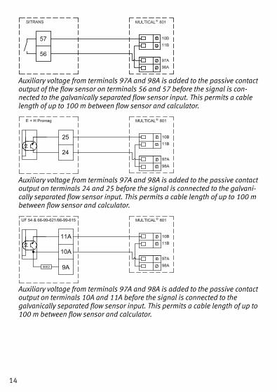
Auxiliary voltage from terminals 97A and 98A is added to the passive contact output of the flow sensor on terminals 56 and 57 before the signal is con-nected to the galvanically separated flow sensor input. This permits a cable length of up to 100 m between flow sensor and calculator.
Auxiliary voltage from terminals 97A and 98A is added to the passive contact output on terminals 24 and 25 before the signal is connected to the galvani-cally separated flow sensor input. This permits a cable length of up to 100 m between flow sensor and calculator.
Auxiliary voltage from terminals 97A and 98A is added to the passive contact output on terminals 10A and 11A before the signal is connected to the galvanically separated flow sensor input. This permits a cable length of up to 100 m between flow sensor and calculator.

15
8. Data modules
8.1 GSM/GPRS module (GSM6H), type 67-0ZThe GSM/GPRS module functions as transparent communication path between reading software and MULTICAL® 602 and is used for data reading. The module includes an external dual-band GSM antenna which must always be used. The module itself includes a line of light emitting diodes indicating signal strength which are very useful during installation.Further details about the GSM/GPRS module appear from data sheet (DK: 5810627, GB: 5810628, DE: 5810629, SE: 5810630).
8.2 3G GSM/GPRS module (GSM8H), type 67-0ULike GSM6H this module functions as transparent communication path between reading software and MULTICAL® 801 and is used for data reading.However, this module supports both 2G (GSM/GPRS) and 3G (UMTS) which makes it applicable in areas with 3G coverage only.The module requires an external Antenna, which covers both 900 MHz, 1800 MHz and 2100 MHz.The module itself is fitted with a line of light emitting diodes indicating signal strength which are very useful during installation. Furthermore, it is indicated whether the module is connected to a 2G or a 3G network.Additional details about the 3G module appear from data sheet (DK: 58101057, GB: 58101058, DE: 58101059, FI: 58101061, SE: 58101060).

16
8.3 Ethernet/IP module (IP201), type 67-0TThe IP module functions as transparent communication between reading software and MULTICAL® 602 and is used for data reading. The module supports both dynamic and static addressing. This is specified in the order or selected during subsequent configuration. The module has no built-in security and must, therefore, always be used in connection with a firewall or NAT. Further details appear from the data sheet (DK: 5810541, GB: 5810542, DE: 5810543, SE: 5810544).
8.4 M-Bus, type 67-00-20/67-00-27/67-00-29/67-0V/67-0P/ 67-0Q
M-Bus can be mounted in star, ring or bus topology. Depending on the power supply of the M-Bus Master as well as the total cable resistance, up to 250 meters can be connected.
Cable resistance < 29 OhmCable capacity < 180 nFThe M-Bus network is to be connected to terminals 24 and 25. The polarity is unimportant. M-Bus is supplied with pulse inputs (at module 1 only which is located nea-rest the terminals).

17
8.5 Radio + pulse inputs, type 67-00-21/67-0W
The radio module is used for wireless communication via a license-free radio frequency and is available for internal or external antenna.For further information on radio please refer to Technical Description for Radio (5512-013).The pulse inputs in this module are identical with the ones described earlier.
8.6 Prog. data logger + RTC + 4…20 mA inputs + pulse inputs, type 67-00-22
The module has connection possibility for two pressure transmitters on terminals 57, 58 and 59 and can be adjusted for current reading or pressure range 6, 10 or 16 bar.The module is prepared for remote reading, data from meter/mo-dule being transferred to the system software via the external GSM/GPRS modem connected on terminals 62, 63 and 64.Furthermore, the module has two extra pulse inputs, VA and VB. The module must be powered by 24 VAC.
8.7 Lon Works, type 67-00-24/67-0YRe mounting of Lon Works type 67-00-24, see installation guide 5512-396 (DK) or 5512-403 (GB).

18
8.8 Wireless M-Bus, type 67-00-30/67-00-35The radio module has been designed to form part of the hand-held Wireless M-Bus Reader systems of Kamstrup A/S at license-free radio frequency (868 MHz).The module fulfils the C-mode specifications of prEN13757-4 and can thus form part of other systems using Wireless M-Bus C-mode communication.The radio module comes with internal antenna and external an-tenna connection as well as two pulse inputs, which are identical with the previously described pulse inputs.The Wireless M-Bus radio transmitter is switched off on dispatch from the factory. It turns on automatically when one litre of water has run through the meter. The radio transmitter can also be swit-ched on by means of a forced dial-up to the meter (keep both front keys pressed for approx. 5 s. until CALL is displayed).
8.9 ZigBee® + pulse inputs, type 67-00-60The ZigBee® module is used for wireless communication and can form part of a remote reading system, in which several units can communicate with each other.The pulse inputs of this module are identical with the previously described pulse inputs.The ZigBee® module (67-00-60) requires mains supply.
8.10 Metasys N2 + pulse inputs (VA, VB), type 67-00-62The N2 module is used for data communication between meter and N2 Master in a Johnson Controls System.The RS485 port is galvanically separated from the meter.The pulse inputs of this module are identical with the previously described pulse inputs.The N2 module (67-00-62) requires mains supply.

19
8.11 SIOX module (Auto detect Baud rate), type 67-00-64/ 67-0M
SIOX is used for data reading of small and medium-sized groups of heat meters via cable, the data readings being presented by the main system, e.g. Mcom, Fix or Telefrang. Further information on these systems can be ordered from the supplier in question. Furthermore, a configuration tool is available from Telefrang. The two-wire serial SIOX bus connection is optoisolated from the meter and is connected without regard to polarity (i.e. the polarity is unimportant). The module is powered by the SIOX bus. Communication speed between 300 and 19,200 baud. The module automatically uses the highest possible communication speed. The module converts data from KMP protocol to SIOX protocol.
8.12 BACnet®, type 67-00-66The BACnet® module communicates with BACnet® on MS/TP via RS-485 as a master/slave or slave device.The BACnet® module transfers a number of both actual data as well as accumulated data.Furthermore, info codes for general alarm, flow error, temperature, error, water leakage, pipe burst, air in system, and wrong flow direc-tion can be transmitted to the BACnet® Controller.The two pulse inputs allow connection and reading of two additio-nal meters for e.g. water and electricity with pulse output.

20
8.13 High Power Radio Router + 2 pulse inputs (VA, VB), type 67-00-84
The High Power RadioRouter module has built-in router functionality and is thus optimized to form part of a Kamstrup radio network, the read data being automatically transferred to system software via the network unit RF Concentrator.Furthermore, the module can be read by Kamstrup’s hand-held reading systems, e.g. USB Meter Reader and MULTITERM Pro.The RadioRouter module is available for operation in both licence-free and licence demanding frequences permitting a transmitting strength of up to 500 mW. The module is by default fitted with internal antenna, connection for external antenna, and two extra pulse inputs.

21
8.14 Module overviewMULTICAL® 801 Communication modules #2Type No. Description Module No.
67-0M SIOX module (Auto detect baud rate) 5920-193
67-0P M-Bus module with alternative registers + pulse inputs 5550-997
67-0Q M-Bus module with MULTICAL® III data package + pulse inputs
5550-1104
67-0T Ethernet/IP module (IP201) 5550-844
67-0U 3G GSM/GPRS module (GSM8H) 5550-1209
67-0V M-Bus module 5550-831
67-0W RadioRouter module 5550-805
67-0Y LonWorks module, FTT-10A 5550-1128
67-0Z GSM6H module excl. external antenna 5550-1137
MULTICAL® 801 Communication modules #1Type No. Description Module No.
67-00-20 M-Bus module with pulse inputs - alternative registers 5550-831
67-00-21 RadioRouter module with pulse inputs 5550-805
67-00-22 Prog. data logger + RTC + 4...20mA inputs + pulse inputs 5550-925
67-00-24 LonWorks module, FTT-10A with pulse inputs 5550-1128
67-00-27 M-Bus module with pulse inputs - alternative registers 5550-997
67-00-29 M-Bus module with pulse inputs - MULTICAL® III compatible data
5550-1125
67-00-30 Wireless M-Bus, C1, standard registers, encrypted, 868 MHz, internal and external antenna, pulse inputs
5550-1097
67-00-35 Wireless M-Bus, C1, alternative registers, encrypted, 868 MHz, internal and external antenna, pulse inputs
5550-1200
67-00-60 ZigBee® 2.4 GHz with internal antenna + pulse inputs 5550-992
67-00-62 Metasys N2 (RS-485) + 2 pulse inputs (VA, VB) module 5550-1110
67-00-64 SIOX module (Auto detect baud rate) 5920-193
67-00-66 BACnet® MS/TP (B-ASC) RS485 + 2 pulse inputs 5550-1240
67-00-84 High Power Radio Router + pulse inputs 5550-1221

22
8.15 Insertion of modulesData modules are retrofitted by placing the module in the PCB hol-der in the left side of the meter and ”clicking” on the module.
Module and meter are electrically connected using a 6-pole jumper.

23
9. Information codes “INFO”
MULTICAL® 801 constantly monitors a series of important functions. If a serious error occurs in the measuring system or in the instal-lation, “INFO” appears in the display and an info code can be read by activating the upper front plate button until the measuring unit shows “INFO” in the display. The info code is only visible while the error exists.
Info code
Description Response time
0 No irregularities -
1 Supply voltage has been cut off -
8 Temperature sensor T1 outside measuring range 1…10 min.
4 Temperature sensor T2 outside measuring range 1…10 min.
32 Temperature sensor T3 outside measuring range 1…10 min.
64 Leak in the cold-water system 24 hours
256 Leak in the heating system 24 hours
512 Burst in the heating system 120 sec.
ULTRAFLOW® 54 info (if activated CCC=4XX)
16 Flow sensor V1, Datacomm error After reset and 1 day (00:00)
1024 Flow sensor V2, Datacomm error After reset and 1 day (00:00)
2048 Flow sensor V1, Wrong meter factor After reset and 1 day (00:00)
128 Flow sensor V2, Wrong meter factor After reset and 1 day (00:00)
4096 Flow sensor V1, Signal too low (Air) After reset and 1 day (00:00)
8192 Flow sensor V2, Signal too low (Air) After reset and 1 day (00:00)
16384 Flow sensor V1, Wrong flow direction After reset and 1 day (00:00)
32768 Flow sensor V2, Wrong flow direction After reset and 1 day (00:00)

24
10. Terminal Overview
MULTICAL® 801 has many connection options. The terminals are placed at the bottom of the meter.
5512603_B3_GB_12.2013

Consumed energy in kWh, MWh or GJ
Consumed district heating water
Number of operating hours
Latest yearly target date
Energy consumption count on latest yearly target date, followed by previous yearly target dateFollowed by monthly target date data
Date of latest yearly target date
District heating water volume count on latest yearly target date, followed by previous yearly target dateFollowed by monthly target date data
Current inlet pipe temperature(*) Press to see yearly and
monthly average values
Current outlet pipe tempe-rature (*) Press to see yearly and
monthly average values
Current temperature dif-ference
Current water flow(*) Press to see the peak
value of the current year and historic yearly and monthly values
Current heat power(*) Press to see the peak
value of the current year and historic yearly and monthly values
Followed by totalized water consumption on input A and B.
5512603_B3_GB_12.2013

The first max. 8 digits of the customer number The latest 8 digits of the
customer number. This example displays customer number 12345678912
Current date
Current time
The target date appears in the order of month and day. In this example 1 June
The counter’s serial number
The counter’s program number. In this example: Installed in outlet flow, MWh and 100 imp/l.Followed by the calculator’s configuration number and software edition.
Display segment test
DDD = 213(*) DDD = 212
Also see interactive user guides at www.kamstrup.com
Indication of the number of current and corrected error conditions
Data logger indicates the date …
… and the INFO code of the latest 36 changes
Current information code(contact the utility if the figure differs from ”0”)
5512603_B3_GB_12.2013