Insta-Valve 250 PatriotTM - hydra-stop.com · 2.4.0 Setting up the Hydra-Tapper for valve insertion...
27
Insta-Valve 250 Patriot TM 4”-12” Nominal Size Installation Instructions IV250MAN 4”-12” IV 250 v1.91 Revised 09/27/2017
Transcript of Insta-Valve 250 PatriotTM - hydra-stop.com · 2.4.0 Setting up the Hydra-Tapper for valve insertion...

Insta-Valve 250 PatriotTM
4”-12” Nominal Size
Installation Instructions
IV250MAN 4”-12” IV 250 v1.91 Revised 09/27/2017

blank
Th is is supposed to be on the 2nd page
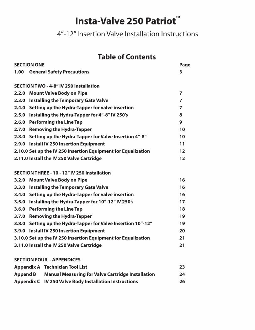
Table of ContentsSECTION ONE Page
1.00 General Safety Precautions 3
SECTION TWO - 4-8” IV 250 Installation
2.2.0 Mount Valve Body on Pipe 7
2.3.0 Installing the Temporary Gate Valve 7
2.4.0 Setting up the Hydra-Tapper for valve insertion 7
2.5.0 Installing the Hydra-Tapper for 4”-8” IV 250’s 8
2.6.0 Performing the Line Tap 9
2.7.0 Removing the Hydra-Tapper 10
2.8.0 Setting up the Hydra-Tapper for Valve Insertion 4”-8” 10
2.9.0 Install IV 250 Insertion Equipment 11
2.10.0 Set up the IV 250 Insertion Equipment for Equalization 12
2.11.0 Install the IV 250 Valve Cartridge 12
SECTION THREE - 10 - 12” IV 250 Installation
3.2.0 Mount Valve Body on Pipe 16
3.3.0 Installing the Temporary Gate Valve 16
3.4.0 Setting up the Hydra-Tapper for valve insertion 16
3.5.0 Installing the Hydra-Tapper for 10”-12” IV 250’s 17
3.6.0 Performing the Line Tap 18
3.7.0 Removing the Hydra-Tapper 19
3.8.0 Setting up the Hydra-Tapper for Valve Insertion 10”-12” 19
3.9.0 Install IV 250 Insertion Equipment 20
3.10.0 Set up the IV 250 Insertion Equipment for Equalization 21
3.11.0 Install the IV 250 Valve Cartridge 21
SECTION FOUR - APPENDICES
Appendix A Technician Tool List 23
Append B Manual Measuring for Valve Cartridge Installation 24
Appendix C IV 250 Valve Body Installation Instructions 26
Insta-Valve 250 PatriotTM
4”-12” Insertion Valve Installation Instructions

SECTION 1.00GENERAL SAFETY PRECAUTIONS - READ AND FOLLOW INSTRUCTIONSCarefully read and understand all safety messages in this manual before using the equipment. The manuals provided with the equalization pump must also be read for safety. The maintenance procedures are to be followed to keep the equipment in good working condition.
PERSONAL PROTECTIONHydra-Stop recommends that installers wear required per-sonal protective equipment including but not limited to:• Hard Hat• Safety Shoes• Safety Glasses• Ear Protection• GlovesAvoid wearing jewelry, such as rings, wristwatches, neck-laces, or bracelets. If working near traffi c, select ear protec-tion that allows you to hear the traffi c for safety.
KEEP SPECTATORS AWAY FROM INSTALLATION AREAKeep all spectators and other workers away from machines and work area(s) while in operation.
CLEAR WORK AREAClear the work area of all objects that might interfere with the proper operation of any tools. Avoid placing tools or other objects where they can fall into the pit.
DO NOT WORK IN AN UNSUPPORTED TRENCHDo not work in trench with unstable sides, which could cave in. Specifi c requirements for shoring or sloping trench walls are available from several sources including federal and state offi ces. Be sure to contact suitable authorities for these requirements before working in the trench. A mini-mum 5’x 5’ excavation is recommended.Locate the existing pipe joints or fi ttings in the area and use the appropriate restraint methods if necessary. CHECK LAWS AND REGULATIONSKnow and obey all Federal, State, and local laws and regu-lations that apply to your work situation.
HANDLING THE EQUIPMENTTo avoid back injury, use proper lifting techniques. Follow all equipment instructions when lifting heavy loads.
CHECK HARDWARE AND EQUIPMENTMake sure that all air or hydraulic line couplings are tight-ened and secured to eliminate the chance of accidental uncoupling. Use hose connection retaining devices such as locking rings, clips, pins, chains, or cables. Identify all equipment and tools necessary for the size of IV 250 you intend to install. Please refer to the attached tool list (See Appendix A). Inspect equipment to verify it is in good working condition and free of wear and damage prior to use. Never start an operation if the equipment is not in proper working order. Contact Hydra-Stop if equipment is not in working order.
DO NOT EXCEED LOAD RATING ON ANY LIFT-ING EQUIPMENTThis includes but is not limited to lifting magnets, eyebolts and straps. Lifting magnets provided with Hydra-Stop equipment are labeled with a load rating. 12” knife gate lifting assists and ¾” eye bolts should ONLY be used for lifting 12” and 8” temporary gate valves respectively.
WARNING: Failure to follow any of the above safety instructions or those that follow in this manual, could result in serious injury. Any operation involving work on pipe containing liquids or gases under pressure is potentially hazardous. It is necessary, therefore, that correct proce-dures be followed in the use and maintenance of this equip-ment to maintain a safe working environment.
No person should use this equipment who is not fully trained in the procedures stated in this manual, and who is not fully aware of the potential hazards connected with work on pipe containing liquids or gases under pressure.
The purchaser of this equipment is responsible for the manner in which this equipment is used, maintained and the training, competence and safety of the operators.
Should any diffi culty arise at any time in the use of this equipment, please contact HYDRA-STOP at 708-389-5111 immediately.
GENERAL SAFETY WARNINGS


Section 2 4 - 8” IV 250 Installation
Instructions

IV 250 Installation Instructions 7 IV250MAN IV 250 v1.91 Revised 09/27/2017
2.2.0 Mount & Pressure Test Valve Body on Pipe2.2.1) Select the proper IV 250 for installation. Identify the type of pipe the IV 250 will be installed on. Accurately measure the outside diameter of the pipe.
2.2.2) Refer to the attached IV 250 Valve Body Installation In-structions. See Appendix C.
2.3.0 Installing the Temporary Gate Valve2.3.1) Install the temporary gate valve. 4”, 6” and 8” IV 250’s use the 8” temporary gate valve. If possible avoid positioning the valve at the true 3, 6, 9 or 12 o’clock position to allow access to the completion plug pins.
Temporary gate valves are single direction valves and must be positioned top up. The 8” gate temporary valve must be installed with the o-ring groove facing up.
2.3.2) Bolt the temporary gate valve to the top of the IV 250 fl ange using the bolts, nuts and washers provided with the instal-lation equipment. We recommend using a cross-tightening pattern.
2.3.3) Install the o-ring in the groove of the 8” temporary gate valve. (See Figure 1)
2.3.4) Fully open the temporary gate valve.
If you own an Aluminum Temporary Gate Valve: Fully
close the temporary gate valve and count the number of turns to open. This is important to know in order
to check clearance issues later.
2.4.0 Setting up the Hydra-Tapper2.4.1) Select proper size saw mandrel. Tapping of the 4”-8” IV 250 requires the 41” long saw mandrel.
2.4.2) Select proper size shell cutter. Hydra-Stop valve insertion shell cutters are shipped painted black. If you repaint valve inser-tion shell cutters in the future, Hydra-Stop recommends painting them black.
Installation of 4 inch IV 250 - requires 3.8 inch cutter
Installation of 6 inch IV 250 - requires 5.8 inch cutter
Installation of 8 inch IV 250 - requires 7.9 inch cutter
Do not use red painted shell cutters to install the IV 250. Hydra-Stop side tap shell cutters are shipped painted red. Red painted side tap shell cutters are ½” undersized for side tapping.
2.4.3) Select proper size pilot drill.
Installation of 4” & 6” IV 250’s require the 5/8” X 6” long pilot drill. Installation of 8” IV 250’s require the 5/8” X 7-1/4” length pilot drill.
Tapping PVC or steel pipe will require a twist style pilot drill.Failure to use the proper sized or type of pilot drill will result in a failed installation.
2.4.4) Loosen and remove the allen head pilot drill retaining set screw located on the side of the saw mandrel fl ange base.
2.4.5) Visually locate the tapered relief on the base of the pilot drill. Notice the stop or ledge at the base of the taper. (See Fig. 2)
2.4.6) Mark the fl at of the taper with a visible marking agent. (See Figure 3)
2.4.7) Align the pilot drill fl at with the allen head set screw and insert the pilot drill through the center of the saw mandrel stud. (See Figure 4)
Figure 1
Figure 3
Figure 2
Figure 4

IV 250 Installation Instructions 8 IV250MAN IV 250 v1.91 Revised 09/27/2017
2.4.8) Confi rm you have completely inserted the pilot drill and engaged the tapered fl at. Look into set screw hole for the mark-ing on the pilot drill. Adjust the pilot drill until you can see the marking. (See Figure 5)
2.4.9) Once aligned, insert and tighten the set screw. Test pull the pilot drill to ensure the set screw is properly locked in place against the pilot drill ledge. Check the coupon retaining clips so they move freely. (See Figure 6 )
Wear gloves when pulling on the pilot drill. Edges may be sharp.
2.4.10) Loosen and back out the 2 allen head cap screws on the fl ange of the saw mandrel until fl ush with the face of the fl ange.
2.4.11) Thread the appropriate shell cutter all the way onto the threaded stud of the saw mandrel fl anged end.
2.4.12) Back off to align the holes in the base of the shell cutter with the allen head cap screws and thread them through the holes. Tighten allen head cap screws.
2.4.13) Make sure the saw mandrel is clean and free of rust or grime (steel wool can be used to clean and smooth the surface).
2.4.14) Lubricate the end of the saw mandrel with a dab of the food grade lubricant provided with the equipment to help it slide freely through the packing nut assembly.
2.4.15) Slide the assembled shell cutter and saw mandrel into the Hydra-Tapper until the saw mandrel fl ange bottoms out in the Hydra-Tapper.
2.4.17) Hand tighten the clamp lever on the packing nut assembly to keep the assembled shell cutter and saw mandrel in place.
Do not use tools to tighten the clamp lever.
2.5.0 Installing the Hydra-Tapper for 4”-8” IV 250 Installation2.5.1) Using a strap or sling install the assembled Hydra-Tapper on to the 8” temporary gate valve and align the bolt slots.
Use extreme caution not to damage the shell cutter or pilot drill as the unit is raised and positioned on to the temporary valve. Note the position of the fully retracted cutting assembly.
2.5.2) Install and cross tighten the bolts, nuts and washers to secure the assembly. Thread the ¼” nipple and ball valve into the tap housing and wrench tighten. Tefl on tape or thread sealant can be used.
2.5.3) Hold and control the exposed saw mandrel, loosen the packing nut assembly clamp lever and slowly lower the saw mandrel down until the pilot drill is resting on the center top of the pipe. Ensure the shell cutter spins freely in a clock-wise direction.
2.5.4) Slide the stop collar over the saw mandrel.
2.5.5) Set the cutting depth by measuring from the top of the packing nut assembly to the lower side of the stop collar.
• 4” pipe = 3” cutting depth • 6” pipe = 4” cutting depth • 8” pipe = 5” cutting depth
2.5.6) Tighten the stop collar to the correct measurement. (See Figure 7)
2.5.7) Install the drive unit by lifting it above the saw mandrel and slide it into the three guide bars.
Figure 7 (Measurement shown is for reference only)
Figure 5
Figure 6

IV 250 Installation Instructions 9 IV250MAN IV 250 v1.91 Revised 09/27/2017
2.5.8) Lower the drive unit onto the machined hex of the saw mandrel. Confi rm the drive unit is fully seated onto the machined hex of the saw mandrel. (See Figure 8)
2.5.9) Install feed screw by threading it through the top plate of the Hydra-Tapper until the opening covers the spindle on the drive unit.
Do not apply downward force as it can damage the pilot drill.
2.5.10) When the feed screw makes contact with the top of the drive unit, back off one full turn.
2.5.11) Assemble the handle assembly and install over the fl ats at the top of the feed screw and tighten the handles.
2.6.0 Performing the Line Tap2.6.1) Ensure ball valve on the Hydra-Tapper P2 housing is open.
2.6.2) Connect the drive unit power source to the drive unit. The air drive unit requires 90 CFM at 90 PSI. The hydraulic drive unit requires 9 GPM at 1800 PSI.
2.6.3) Ensure the drive unit lever control is in the neutral posi-tion. Always run the power unit in the clockwise direction.
Avoid reversing as this will damage the carbide on the pilot drill and carbide teeth on the shell cutter.
2.6.4) Engage the drive unit and confi rm the saw mandrel is rotat-ing in the clockwise direction. Slowly turn the handle assembly in a clockwise direction keeping slight, constant pressure until the tap is complete.
2.6.5) Close the ball valve on the P2 housing of the Hydra-Tapper as water fi lls the housing and fl ows from the valve.
2.6.6) The tap is complete when the bottom of the stop collar makes contact with the top of the packing nut assembly.
Do not overfeed the tap. Overfeeding the tap will cause the shell cutter to jam.
2.6.7) Return the drive unit lever control to the neutral position.
2.6.8) Loosen stop collar and continue to advance the feed screw an additional two complete revolutions to ensure the cut is complete. The shell cutter should spin freely. If it does, discon-nect the drive unit power source from the drive unit. If the shell cutter does not spin freely pull the drive unit lever control down and confi rm the saw mandrel is rotating in a clockwise direction. Slowly turn the handle assembly in a clockwise direction an addi-tional two complete revolutions. Repeat steps 2.6.6 and 2.6.7
2.6.9) Slowly turn the handle assembly in a counterclockwise di-rection until the stop collar has reached the starting measurement. • 4” pipe = 3” cutting depth • 6” pipe = 4” cutting depth • 8” pipe = 5” cutting depth
2.6.10) Tighten the packing nut assembly clamp lever to lock the saw mandrel in place. Remove feed screw. Remove drive unit.
2.6.11) Place a box end wrench over the hex on the saw mandrel and use the wrench as a lever brake to hold in place. (See Figure 9)
2.6.12) Loosen the packing nut assembly clamp lever and allow the pressure to slowly raise the cutter assembly fully into the tapping housing.
2.6.13) Confi rm the shell cutter and saw mandrel assembly is fully retracted and lock the saw mandrel in place by tightening the packing nut assembly clamp lever.
2.6.14) Close the temporary gate valve. If using an aluminum gate valve: make sure you get the same number of turns to close as you counted in step 2.3.4.
Figure 8
Figure 9

IV 250 Installation Instructions 10 IV250MAN IV 250 v1.91 Revised 09/27/2017
2.7.0 Removing the Hydra-Tapper2.7.1) Relieve the pressure from the Hydra-Tapper by opening the ball valve and discharging the pressure.
2.7.2) Connect the slings or straps to the Hydra-Tapper. Unbolt and remove the Hydra-Tapper from the temporary gate valve. Place the Hydra-Tapper in a dry and safe work area.
2.7.3) Remove stop collar.
2.7.4) Remove cutter and saw mandrel assembly.
2.7.5) Remove the coupon by loosening the allen head pilot drill retaining set screw. Remove the pilot drill from the saw mandrel stud.
2.7.6) Flip the pilot drill and insert it point end through the hole in the coupon past the retaining clips and use it to pull the coupon out of the cutter.
Wear gloves when removing the coupon. Coupon edges may be sharp.
2.7.7) Inspect the coupon for pipe thickness and condition.
2.7.8) Remove cutter from saw mandrel.
2.8.0 Setting Up the Hydra-Tapper for 4-8” Valve Insertion2.8.1) Locate the proper valve inserting equipment. Installation of 4”-8” IV 250’s will require the 4”-8” insertion housing, the 48 ½” long insertion tool, and guide plate.
2.8.2) Stand the insertion housing on a fl at surface with the o-ring grooved fl ange facing up. Place the o-ring into the insertion housing o-ring groove. Install the ¾” nipple and ball valve.
2.8.3) Place the Hydra-Tapper on top of the insertion housing with the pointed end of the P3 facing the same direction as the step stand of the housing, Cross tighten with supplied bolts, nuts and washers.
2.8.4) Tip and lay the insertion housing and Hydra-Tapper assem-bly on its stand. (See Figure 10)
2.8.5) The IV 250 valve cartridge consists of top section and bot-tom section. The top section and bottom section must be fi rmly tightened together. Prior to removing operating nut hold the base of the valve cartridge and with a pipe wrench or valve key turn the valve stem fi rmly in the opening direction. (See Figure 11)
2.8.6) Remove the operating nut and the white tefl on washer off of the valve stem and place the end of the insertion tool over the valve stem.
2.8.7) Tighten the IV 250 valve cartridge and insertion tool to-gether by turning the knurled end of the insertion tool clockwise until snug. Tighten the 3/4” insertion tool lock nut located at the base of the knurled handle.
Caution: Ensure there are no gaps between the insertion tool, valve cartridge and feed screw. The valve cartridge should remain in tight contact with the insertion tool and act as a single unit.
2.8.8) Make sure the insertion tool is clean and free of rust or grime (steel wool can be used to clean and smooth the surface). Lubricate the end of the insertion tool with a dab of the food grade lubricant provided with the equipment to help it slide freely through the packing nut assembly. Ensure packing nut assembly clamp lever is loose.
2.8.9) Insert the assembled valve cartridge and insertion tool through the insertion housing / tapping assembly until the top of the valve cartridge is approximately 2.5” from the bottom fl ange of the insertion housing. Make sure the shorter, truncated side of the valve cartridge marked with a star is facing upwards. (See Figure 12).
Figure 10
Figure 11
Figure 12

IV 250 Installation Instructions 11 IV250MAN IV 250 v1.91 Revised 09/27/2017
2.8.10) Setup the IV 250 4”-8” alignment gauge for the size being installed (4”, 6” or 8”). Refer to alignment gauge instructions shipped with 4”-8” IV 250 Alignment Gauge Kit.
2.8.11) Set the curved portion of the alignment gauge within the lock pin groove of the valve cartridge. Slide the valve cartridge and alignment gauge towards the insertion housing until the alignment gauge touches the insertion housing. The two gauge pins will seat in the top two holes of the insertion housing. (See Figure 14).
2.8.12) Ensure the fl at of the alignment gauge arm remains aligned with the truncated side of the valve cartridge. (See Fig-ure 13).
2.8.13) Place the 7.5” IV 250 Insertion Depth Gauge on the insertion tool. Place one end of the insertion gauge against the packing nut assembly. Slide the stop collar towards the inser-tion gauge until the stop collar makes contact with the insertion gauge. This automatically sets the proper depth for insertion. Lock the stop collar.
2.8.14) Slide and place the guide plate to within 2” of the stop collar and lock the clamp lever. (See Figure 15).
2.8.15) Make a reference mark on the insertion housing aligned with the centerline of the Alignment Gauge. (See Figure 14.)
2.8.16) Remove the 7.5” IV 250 Insertion Depth Gauge.
2.8.17) Slide the valve cartridge back to the original 2.5” mea-surement away from the insertion housing. Remove the IV 250 Alignment Gauge.
2.8.18) Lubricate the completion plug o-ring with food grade lubricant provided with the equipment.
2.8.19) Slide the valve cartridge assembly fully into the insertion housing.
2.8.21) Tighten the clamp lever on the packing nut assembly to keep the assembled valve cartridge and insertion tool in place.
Do not use tools to tighten the clamp lever.
2.9.0 Install IV 250 Insertion Equipment2.9.1) Make sure the o-ring in the temporary gate valve is still properly seated in the o-ring groove and safely lift the insertion equipment on to the temporary valve.
2.9.2) Align the insertion housing reference mark made in step 2.8.15 with the point of the pentagon valve body that is in line with the direction of the pipe. (See Figure 16). You may also utilize the “star” on the valve as an alignment reference.
Use the pin plug hole that aligns with the valve body star as an additional alignment reference.
2.9.3) Using the bolts, nuts and washers cross tighten the assem-bly in place.
Figure 16
Figure 13
Figure 15
Figure 14

IV 250 Installation Instructions 12 IV250MAN IV 250 v1.91 Revised 09/27/2017
2.10.0 Set up the IV 250 Insertion Equip-ment for Equalization2.10.1) Install the proper fi tting on to the insertion housing ¾” ball valve. The equalization source will determine the proper fi tting.
2.11.0 Install the IV 250 Valve Cartridge2.11.1) Loosen the packing nut clamp lever. Lower the valve cartridge / insertion tool assembly until it touches the temporary gate valve. Re-tighten the packing nut assembly clamp lever. It is critical to install the 30” feed screw over the knurled spindle of the insertion tool until the feed screw bottoms out on the locking nut washer.
Failure to follow step 2.11.1 could result in damaged equipment and failed installation.
2.11.2) Open the tapping housing and insertion housing ball valves and slowly open the temporary gate valve until the in-sertion housing begins to fi ll. Stop opening the temporary gate valve.
2.11.3) Close the insertion housing ball valve once fl uid reaches the ball valve. Wait for fl uid to reach the tapping housing ball valve and close ball valve. Allow the insertion / tap housings to fully pressurize.
2.11.4) Fully open the temporary gate valve. Count your turns to be sure it is fully open on aluminum gate valves (You do not need to count turns on steel gate valves).
2.11.5) Install the handle assembly over the fl ats at the top of the feed screw and tighten.
2.11.6) Loosen the packing nut assembly clamp lever and begin advancing the valve cartridge insertion assembly. Advancement will stop when the completion plug o-ring makes contact with the valve body fl ange. The stop collar will be approximately 2” from the top of the packing nut assembly. Confi rm this measurement.
Do not start the next step until the 2 inch measurement has been confi rmed. (See Figure 17)
2.11.7) Connect the equalization source and open the insertion housing ball valve.
2.11.8) Pressurize the insertion housing until the pressure in the insertion housing is 5 psi greater than the line pressure. If proper-ly aligned, valve cartridge should seat itself.
2.11.9) Continue advancing the feed screw until the valve car-tridge assembly is completely seated. The valve cartridge assem-bly is completely seated when the bottom of the stop collar makes contact with the top of the packing nut assembly.
NOTE: Measuring errors may prevent the bottom of the stop collar from reaching the top of the packing nut assembly. Do not proceed to step 11 if the distance between the stop collar and the packing nut assembly is greater than 1/8” of an inch. Fully retract the valve cartridge from the installation housing. Close temporary gate valve. Return to 8.0 Setting Up the Hydra-Tapper for Valve Insertion 4”-8” Step 2.8.11 and repeat all installation steps.
2.11.10) Remove pin plugs. Store in a clean and safe location.
2.11.11) Lock the valve cartridge assembly in place by cross tightening the four allen head locking pins. Tighten until the al-len head locking pin makes SLIGHT CONTACT with the com-pletion plug - approximately 7 1/2 full turns. Back off ¼ turn on each pin. Figure 18 below shows a cross tightening pattern which starts with Locking Pin #1 followed by Locking Pin #2, #3 and #4. You may start with any of the locking pins as #1, however, be sure to follow a cross tightening pattern with remaining pins.
NOTE: If you experience excessive leakage from the locking pin ports you can immediately re-install the pin plugs (removed in step 2.11.10) after properly setting the completion plug pins.
Do not start the next step until all completion pins have been properly set. Failure to properly set completion pins could result in hard operation and impact valve perfor-mance. (See Figure 19 on next page).Figure 17
Figure 18* Note: Temporary Gate Valve removed for clarity.
Locking Pins are shown for location purposes only.

IV 250 Installation Instructions 13 IV250MAN IV 250 v1.91 Revised 09/27/2017
2.11.12) Tighten the packing nut assembly clamp lever and retract the feed screw three full turns.
2.11.13) Remove the equalization source. Slowly open the ¾” ball valve on the insertion housing to relieve the pressure in the insertion / tap housings.
2.11.14) Remove the feed screw.
2.11.15) Loosen the insertion tool lock nut three full turns. Turn the knurled handle of the insertion tool counterclockwise until the insertion tool is disengaged from the valve stem.
Ensure the insertion tool does not rotate when turning the knurled handle of the insertion tool.
2.11.16) Loosen the packing nut assembly clamp lever and fully retract the insertion tool. Re-tighten the packing nut assembly clamp lever.
2.11.17) Remove the IV 250 insertion equipment & temporary gate valve. Confi rm o-ring is placed on top of IV 250 fl ange.
2.11.18) Place white tefl on washer onto the valve stem.
2.11.19) Lubricate the o-ring in the bore of the IV 250 bonnet and install over the valve stem.
2.11.20) Align bolt holes.
2.11.21) Cross tighten the bolts, nuts and washers that came with the IV 250.
2.11.22) Set the 2” operating nut on the valve stem. Thread the operating locking nut on to the valve stem.
2.11.23) Locate and install allen head pipe plugs removed during IV 250 valve body installation. Use tefl on tape or thread sealant to ensure a seal.
2.11.24) Full open/close IV 250 to confi rm a successful installa-tion. IV 250 is three turns per inch plus/minus three turns depend-ing on the type and condition of the inside diameter of the pipe.
2.11.25) Fully disassemble, clean and store equipment.
2.11.26) Order replacement parts, if necessary, to replace lost, damaged or worn components.
Figure 19

IV 250 Installation Instructions 14 IV250MAN IV 250 v1.91 Revised 09/27/2017
Section 3 10 - 12” IV 250 Installation
Instructions


IV 250 Installation Instructions 16 IV250MAN IV 250 v1.91 Revised 09/27/2017
3.2.0 Mount & Pressure Test Valve Body on Pipe3.2.1) Select the proper IV 250 for installation. Identify the type of pipe the IV 250 will be installed on. Accurately measure the outside diameter of the pipe.
3.2.2) Refer to the attached IV 250 Valve Body Installation In-structions in Appendix C.
3.3.0 Installing the Temporary Gate Valve3.3.1) Install the temporary gate valve. 10” and 12” IV 250’s use the 12” temporary gate valve. If possible avoid positioning the temporary valve over one of the pin plug ports.
Temporary gate valves are single direction valves and must be positioned top up. The 12” gate temporary valve must be installed with the red bar facing up. (See Figure 1)
3.3.2) Install the fl ange o-ring in the o-ring channel on the IV 250. Carefully lower the 12” temporary gate valve into position. Ensure the temporary gate valve is centered on the valve fl ange.
Failure to center temporary valve could cause mis-align-ment resulting in a failed installation.
3.3.3) Bolt the temporary gate valve to the top of the IV 250 fl ange using the nuts and wash-ers provided with the installation equipment.
3.3.4) Install green fi ber gasket (without holes) on the top side of temporary gate valve. (See Figure 1)
3.3.5) Fully open the temporary valve and re-check that temporary valve is centered.
3.4.0 Setting up the Hydra-Tap-per 3.4.1) Bolt Hydra-Tapper to the P-20 component using the bolts / nuts included with Hydra-Tapper equipment. (See Figure 2)
3.4.2) Select proper size saw mandrel. Tapping of 10” and 12” IV 250’s require the 55” long saw mandrel.
3.4.3) Select proper size shell cutter. Hydra-Stop valve insertion shell cutters are shipped painted black. If you repaint valve inser-tion shell cutters in the future, Hydra-Stop recommends painting them black.
Installation of 10 inch IV 250 - requires 9.8 inch cutter.
Installation of 12 inch IV 250 - requires 11.8 inch cutter.
Do not use red painted shell cutters to install IV 250. Hydra-Stop side tap shell cutters are shipped painted red. Red painted side tap shell cutters are ½” undersized for side tapping.
3.4.4) Select proper size pilot drill.
Installation of 10” and 12” IV 250’s require the 3/4” X 10 5/16” long pilot drill.
Tapping PVC or steel pipe will require a twist style pilot drill.Failure to use the proper sized or type of pilot drill will result in a failed installation.
3.4.5) Loosen and remove the allen head pilot drill retaining set screw located on the side of the saw mandrel fl ange base.
3.4.6) Visually locate the tapered relief on the base of the pilot drill. Notice the stop or ledge at the base of the taper. (See Figure 3)
3.4.7) Mark the fl at of the taper with a visible marking agent. (See Figure 4)
3.4.8) Align the pilot drill fl at with the allen head set screw and insert the pilot drill through the center of saw mandrel stud. (See Figure 5)
Figure 1
Figure 4
Figure 3
Figure 5Figure 2

IV 250 Installation Instructions 17 IV250MAN IV 250 v1.91 Revised 09/27/2017
3.4.9) Confi rm you have completely inserted the pilot drill and engaged the tapered fl at. Look into set screw hole for the mark-ing on the pilot bit. Adjust the pilot drill until you can see the marking. (See Figure 6)
3.4.10) Once aligned, insert and tighten the set screw. Test pull the pilot drill to ensure the set screw is properly locked in place against the pilot drill ledge. Check the coupon retaining clips so they move freely. (See Figure 7 )
Wear gloves when pulling on the pilot bit. Edges may be sharp.
3.4.11) Thread the appropri-ate shell cutter all the way onto the threaded stud of the saw mandrel fl anged end.
3.4.12) Back off cutter to align the holes in the base of the shell cutter with the allen head cap screw holes in the saw mandrel. Thread screws from inside the shell cutters and then into the saw man-drel holes. (See Figure 8).
3.4.13) Thread nylon lock nuts onto allen head cap screws and tighten. (See Figure 9)
3.4.14) Make sure the saw mandrel is clean and free of rust or grime (steel wool can be used to clean and smooth the surface).
3.4.15) Lubricate the end of the saw mandrel with a dab of the food grade lubricant provided with the equipment to help it slide freely through the packing nut assembly.
3.4.16) Slide the assembled shell cutter and saw mandrel into the Hydra-Tapper until the saw mandrel fl ange bottoms out in the P-20 component.
3.4.17) Hand tighten the clamp lever on the packing nut assembly to keep the assembled shell cutter and saw mandrel in place.
Do not use tools to tighten the clamp lever.
3.5.0 Installing the Hydra-Tapper for 10” - 12” IV 250 Installation3.5.1) Using a strap or sling install the assembled Hydra-Tapper on to the 12” temporary gate valve and align the bolt slots.
Use extreme caution not to damage the shell cutter or pilot drill as the unit is raised and positioned on to the temporary valve. Note the position of the fully retracted cutting assembly.
3.5.2) Cross tighten the bolts, nuts and washers to secure the as-sembly. Thread the ¼” nipple and ball valve into the tap housing and wrench tighten. Tefl on tape or thread sealant can be used.
3.5.3) Hold and control the exposed saw mandrel, loosen the clamp lever and slowly lower the saw mandrel until the pilot drill is resting on the top of the pipe. Ensure the shell cutter spins freely in a clock-wise direction.
3.5.4) Slide the stop collar over the saw mandrel.
3.5.5) Set the cutting depth by measuring from the top of the packing nut assembly to the lower side of the stop collar.
3.5.6) Tighten the stop collar to the correct measurement. (See Figure 10) • 10” pipe = 6” cutting depth • 12” pipe = 7” cutting depth
Figure 6
Figure 7
Figure 8
Figure 9 Figure 10
IV 250 Installation Instructions 18 IV250MAN IV 250 v1.91 Revised 09/27/2017
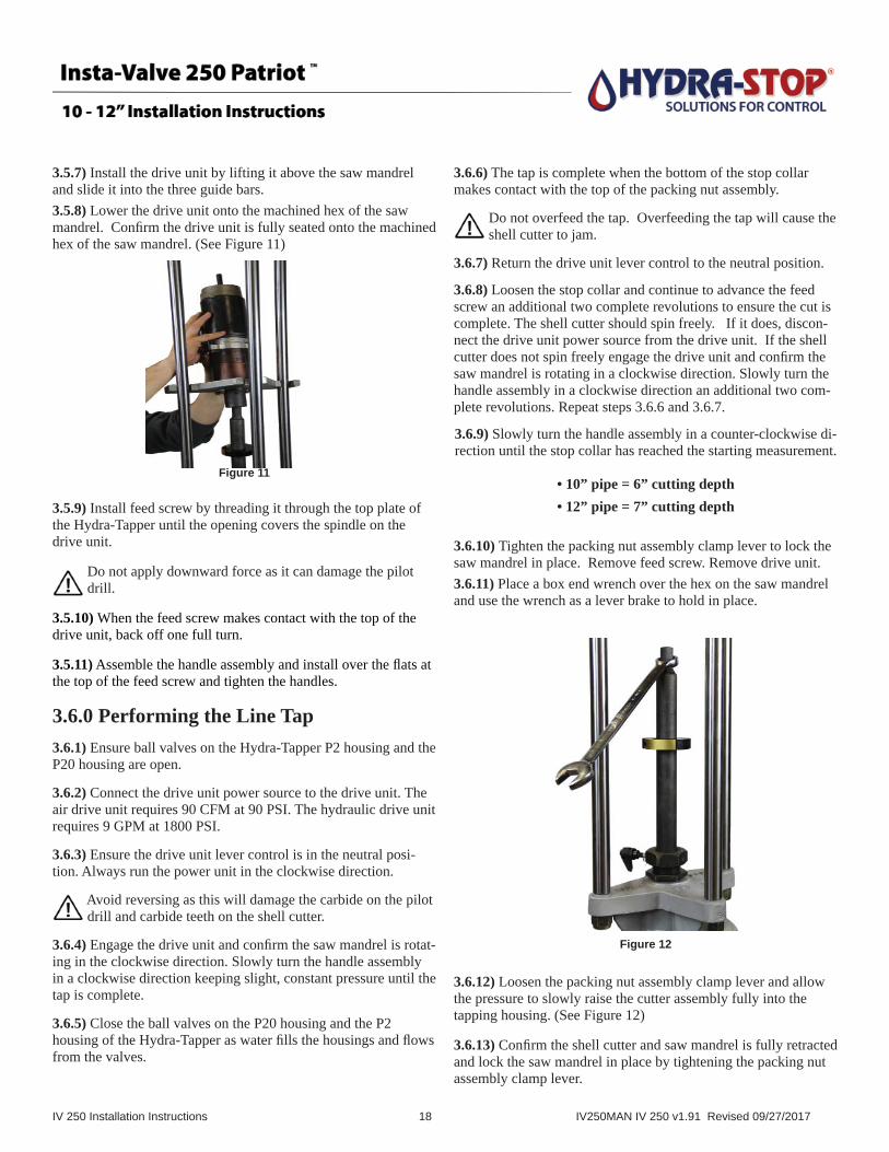
3.5.7) Install the drive unit by lifting it above the saw mandrel and slide it into the three guide bars. 3.5.8) Lower the drive unit onto the machined hex of the saw mandrel. Confi rm the drive unit is fully seated onto the machined hex of the saw mandrel. (See Figure 11)
3.5.9) Install feed screw by threading it through the top plate of the Hydra-Tapper until the opening covers the spindle on the drive unit.
Do not apply downward force as it can damage the pilot drill.
3.5.10) When the feed screw makes contact with the top of the drive unit, back off one full turn.
3.5.11) Assemble the handle assembly and install over the fl ats at the top of the feed screw and tighten the handles.
3.6.0 Performing the Line Tap3.6.1) Ensure ball valves on the Hydra-Tapper P2 housing and the P20 housing are open.
3.6.2) Connect the drive unit power source to the drive unit. The air drive unit requires 90 CFM at 90 PSI. The hydraulic drive unit requires 9 GPM at 1800 PSI.
3.6.3) Ensure the drive unit lever control is in the neutral posi-tion. Always run the power unit in the clockwise direction.
Avoid reversing as this will damage the carbide on the pilot drill and carbide teeth on the shell cutter.
3.6.4) Engage the drive unit and confi rm the saw mandrel is rotat-ing in the clockwise direction. Slowly turn the handle assembly in a clockwise direction keeping slight, constant pressure until the tap is complete.
3.6.5) Close the ball valves on the P20 housing and the P2 housing of the Hydra-Tapper as water fi lls the housings and fl ows from the valves.
3.6.6) The tap is complete when the bottom of the stop collar makes contact with the top of the packing nut assembly.
Do not overfeed the tap. Overfeeding the tap will cause the shell cutter to jam.
3.6.7) Return the drive unit lever control to the neutral position.
3.6.8) Loosen the stop collar and continue to advance the feed screw an additional two complete revolutions to ensure the cut is complete. The shell cutter should spin freely. If it does, discon-nect the drive unit power source from the drive unit. If the shell cutter does not spin freely engage the drive unit and confi rm the saw mandrel is rotating in a clockwise direction. Slowly turn the handle assembly in a clockwise direction an additional two com-plete revolutions. Repeat steps 3.6.6 and 3.6.7.
3.6.9) Slowly turn the handle assembly in a counter-clockwise di-rection until the stop collar has reached the starting measurement.
• 10” pipe = 6” cutting depth• 12” pipe = 7” cutting depth
3.6.10) Tighten the packing nut assembly clamp lever to lock the saw mandrel in place. Remove feed screw. Remove drive unit. 3.6.11) Place a box end wrench over the hex on the saw mandrel and use the wrench as a lever brake to hold in place.
3.6.12) Loosen the packing nut assembly clamp lever and allow the pressure to slowly raise the cutter assembly fully into the tapping housing. (See Figure 12)
3.6.13) Confi rm the shell cutter and saw mandrel is fully retracted and lock the saw mandrel in place by tightening the packing nut assembly clamp lever.
Figure 11
Figure 12

IV 250 Installation Instructions 19 IV250MAN IV 250 v1.91 Revised 09/27/2017
3.6.14) Close the temporary gate valve.
3.7.0 Removing the Hydra-Tapper3.7.1) Relieve the pressure from the Hydra-Tapper by opening the ball valve and discharging the pressure.
3.7.2) Connect the slings or straps to the Hydra-Tapper. Unbolt and remove the Hydra-Tapper / P-20 assembly from the tempo-rary gate valve. Place the assembly in a dry and safe work area.
3.7.3) Remove stop collar.
3.7.4) Remove cutter and saw mandrel assembly.
3.7.5) Remove the coupon by loosening the allen head pilot drill retaining set screw. Remove the pilot drill from the saw mandrel stud.
3.7.6) Flip the pilot drill and insert it point end through the hole in the coupon past the retaining clips and use it to pull the coupon out of the cutter.
Wear gloves when removing the coupon. Coupon edges may be sharp.
3.7.7) Inspect the coupon for pipe thickness and condition.
3.7.8) Remove cutter from saw mandrel.
3.8.0 Setting Up the Hydra-Tapper for 10” - 12” Valve Insertion3.8.1) Locate the proper valve inserting equipment. Installation of 10”-12” IV 250’s will require the 10”-12” insertion housing, the 59” long insertion tool, the guide plate and a stop collar.
3.8.2) Stand the insertion housing on a fl at surface. Place a green fi ber gasket (included with equipment) between the insertion
housing and the tapping machine / P 20 assembly. Install the ¾” nipple and ball valve.
3.8.3) Place the Hydra-Tapper / P-20 assembly on top of the insertion housing with the pointed end of the P3 facing the same direction as the step stand of the housing, Cross tighten with supplied bolts, nuts and washers.
3.8.4) Tip and lay the insertion housing and Hydra-Tapper / P20 assembly on its stand. (See Figure 13)
3.8.5) The IV 250 valve cartridge consists of top section and bot-tom section. The top section and bottom section must be fi rmly tightened together. Prior to removing operating nut hold the base of the valve cartridge and with a pipe wrench or valve key turn the valve stem fi rmly in the opening direction. (See Figure 14)
3.8.6) Remove the operating nut and the white thrust washer off of the valve stem and place the end of the insertion tool over the valve stem.
3.8.7) Tighten the IV 250 valve cartridge and insertion tool to-gether by turning the knurled end of the insertion tool clockwise until snug. Tighten the 3/4” insertion tool lock nut located at the base of the knurled handle.
Caution: Ensure there are no gaps between the insertion tool, valve cartridge and feed screw. The valve cartridge should remain in tight contact with the insertion tool and act as a single unit.
3.8.8) Make sure the insertion tool is clean and free of rust or grime (steel wool can be used to clean and smooth the surface). Lubricate the end of the insertion tool with a dab of the food grade lubricant provided with the equipment to help it slide freely through the packing nut assembly. Ensure packing nut assembly clamp lever is loose.
3.8.9) Insert the assembled valve cartridge and insertion tool through the insertion housing / tapping assembly until the top of the valve cartridge is approximately 2.5” from the bottom fl ange of the insertion housing. Make sure the shorter, truncated side of the valve cartridge is facing upwards. (See fi gure 15 on next page.)Figure 13
Figure 14

IV 250 Installation Instructions 20 IV250MAN IV 250 v1.91 Revised 09/27/2017
3.8.10) Slide the stop collar over the knurled end of the insertion tool. Align the 3 slots of the triangular shaped guide plate with the 3 guide bars and slide it over the knurled end of the insertion tool.
3.8.11) Setup the IV 250 10”-12” Alignment Gauge for the size being installed (10” or 12”). Refer to Alignment Gauge instruc-tions shipped with 10”-12” IV 250 Alignment Gauge Kit.
3.8.12) Set the curved portion of the alignment gauge within the lock pin groove of the valve cartridge. Slide the valve cartridge and alignment gauge towards the insertion housing until the alignment gauge touches the insertion housing. The two gauge pins will seat in the top two holes of the insertion housing. (See Figure 17).
3.8.13) Ensure the fl at of the alignment gauge arm remains aligned with the truncated side of the valve cartridge. (See Fig-ure 16).
3.8.14) Place the 4.25” IV 250 Insertion Gauge on the insertion tool. Place one end of the insertion gauge against the packing nut assembly. Slide the stop collar towards the insertion gauge until the stop collar makes contact with the insertion gauge. This auto-matically sets the proper depth for insertion. Lock the stop collar.
3.8.15) Make a reference mark on the insertion housing inline with the alignment gauge centerline. (See Figure 17)
3.8.16) Slide and place the guide plate to within two inches of the stop collar and lock the clamp lever. (See Figure 18).
3.8.17) Remove the 4.25” IV 250 Insertion Gauge.
3.8.18) Slide the valve cartridge back to the original 2.5” mea-surement away from the insertion housing. Remove the IV 250 Alignment Gauge.
3.8.19) Lubricate the completion plug o-ring with food grade lubricant provided with the equipment.
3.8.20) Slide the valve cartridge assembly fully into the insertion housing.
3.8.21) Tighten the clamp lever.
Do not use tools to tighten the clamp lever.
3.9.0 Install IV 250 Insertion Equipment3.9.1) Place a green fi ber gasket with holes (included with equipment) between the insertion housing and the temporary gate valve. Safely lift the insertion equipment and place on to the temporary valve.
3.9.2) Align the insertion housing reference mark made in step 3.8.15 with the point of the pentagon valve body that is in line with the direction of the pipe. (See Figure 19)
Figure 19
Figure 16
Figure 18
Figure 17
Figure 15

IV 250 Installation Instructions 21 IV250MAN IV 250 v1.91 Revised 09/27/2017
NOTE: Use the pin plug hole that aligns with the valve body pentagon point as an additional alignment reference.
3.9.3) Thread nuts and washers provided and cross tighten the insertion assembly in place.
3.10.0 Set up the IV 250 Insertion Equip-ment for Equalization3.10.1) Install the proper fi tting on to the insertion housing ¾” ball valve. The equalization source will determine the proper fi tting size and type.
3.11.0 Install the IV 250 Valve Cartridge3.11.1) Loosen the packing nut clamp lever. Lower the valve cartridge until in touches the temporary gate valve. It is critical to install the 30” feed screw over the knurled spindle of the insertion tool until the feed screw bottoms out on the locking nut washer.
Failure to follow step 3.11.1 could result in damaged equipment and failed installation.
3.11.2) Open the tapping housing and insertion housing ball valves and slowly open the temporary gate valve until the in-sertion housing begins to fi ll. Stop opening the temporary gate valve.
3.11.3) Close the insertion housing ball valve once fl uid reaches the ball valve. Wait for fl uid to reach the tapping housing ball valve and close ball valve. Allow the insertion / tap housings to fully pressurize.
3.11.4) Fully open the temporary gate valve.
3.11.5) Install the handle assembly over the fl ats at the top of the feed screw and tighten.
3.11.6) Loosen the packing nut assembly clamp lever and begin advancing the valve cartridge insertion assembly. Advancement will stop when the completion plug o-ring makes contact with the valve body fl ange. The stop collar will be approximately 2” from the top of the packing nut assembly. Confi rm this measurement.
Do not start the next step until the 2 inch measurement has been confi rmed. (See Figure 20)
3.11.7) Connect the equalization source and open the inser-tion housing ball valve.
3.11.8) Pressurize the insertion housing until the pressure in the insertion housing is 5 psi greater than the line pressure.
3.11.9) Continue advancing the feed screw until the valve cartridge assembly is completely seated. The valve cartridge assembly is completely seated when the bottom of the stop collar makes contact with the top of the packing nut assembly (within 1/8 of an inch.).
CAUTION: The feedscrew should advance easily during the valve cartridge install process. If excessive effort is required to advance feedscrew the valve cartridge is mis-aligned. Imme-diately stop the valve cartridge installation process, retract the valve cartridge into the installation housing and close the tempo-rary gate valve. Remove equipment and return to step 3.8.1 and repeat all installation steps.
NOTE: Measuring errors may prevent the bottom of the stop collar from reaching the top of the packing nut assembly. Do not proceed to step 11 if the distance between the stop collar and the packing nut assembly is greater than 1/8” of an inch. Fully retract the valve cartridge from the installation housing. Close temporary gate valve. Return to 3.8.0 Setting Up the Hydra-Tap-per for Valve Insertion 10”-12” Step 3.8.11 and repeat all installation steps.
3.11.10) Remove Pin Plugs. Store in a clean and safe location.
3.11.11) Lock the valve cartridge assembly in place by cross tightening the six allen head completion plug pins. Tighten until the allen head locking pin makes SLIGHT CONTACT with the completion plug - approximately 10-1/2 full turns. Back off ¼ turn on each pin. Figure 21 below shows a cross tightening pattern which starts with Locking Pin #1 followed by Locking Pin #2, #3, #4, #5 and #6.
Figure 20
Figure 21* Note: Temporary Gate Valve removed for clarity.
Locking Pins are shown for location purposes only.
IV 250 Installation Instructions 22 IV250MAN IV 250 v1.91 Revised 09/27/2017
You may start with any of the locking pins as #1, however, be sure to follow a cross tightening pattern with remaining pins.
NOTE: If you experience excessive leakage from the locking pin ports you can immediately re-install the pin plugs (removed in step 3.11.10) after properly setting the completion plug pins.
Do not start the next step until all completion pins have been properly set. Failure to properly set completion pins could result in hard operation and impact valve performance. (See Figure 22)
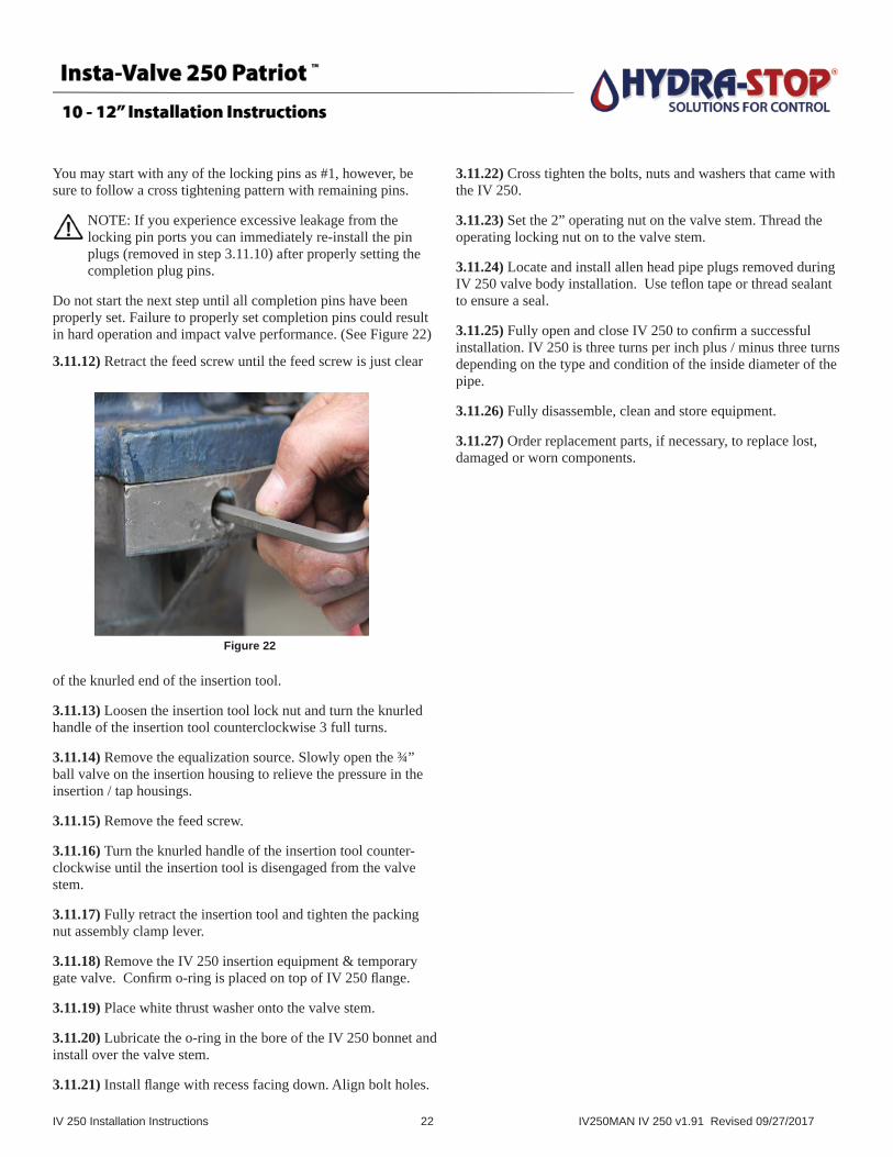
3.11.12) Retract the feed screw until the feed screw is just clear
of the knurled end of the insertion tool.
3.11.13) Loosen the insertion tool lock nut and turn the knurled handle of the insertion tool counterclockwise 3 full turns.
3.11.14) Remove the equalization source. Slowly open the ¾” ball valve on the insertion housing to relieve the pressure in the insertion / tap housings.
3.11.15) Remove the feed screw.
3.11.16) Turn the knurled handle of the insertion tool counter-clockwise until the insertion tool is disengaged from the valve stem.
3.11.17) Fully retract the insertion tool and tighten the packing nut assembly clamp lever.
3.11.18) Remove the IV 250 insertion equipment & temporary gate valve. Confi rm o-ring is placed on top of IV 250 fl ange.
3.11.19) Place white thrust washer onto the valve stem.
3.11.20) Lubricate the o-ring in the bore of the IV 250 bonnet and install over the valve stem.
3.11.21) Install fl ange with recess facing down. Align bolt holes.
3.11.22) Cross tighten the bolts, nuts and washers that came with the IV 250.
3.11.23) Set the 2” operating nut on the valve stem. Thread the operating locking nut on to the valve stem.
3.11.24) Locate and install allen head pipe plugs removed during IV 250 valve body installation. Use tefl on tape or thread sealant to ensure a seal.
3.11.25) Fully open and close IV 250 to confi rm a successful installation. IV 250 is three turns per inch plus / minus three turns depending on the type and condition of the inside diameter of the pipe.
3.11.26) Fully disassemble, clean and store equipment.
3.11.27) Order replacement parts, if necessary, to replace lost, damaged or worn components.
Figure 22

IV 250 Installation Instructions 23 IV250MAN IV 250 v1.85 Revised 09/12/2016
Appendix A - Technician Tool List
Miscellaneous SuppliesTape Measure Torpedo Level Channel Lock Pliers Waterproof or Paint Marker Tefl on Tape WD-40 Chlorine Sprayer Spray bottle with soap & waterFood Grade Grease (such as Primo-Lube) Pressure Test Kit including nipple assembly
Wrenches and Ratchets1/2 or 3/4 drive Ratchet Wrench15/16” Socket 1-1/16” Extra Deep Socket1-1/4” Extra Deep Socket1-5/16” Extra Deep Socket1-7/16” Extra Deep Socket
Allen Wrenches9 / 16” Allen Wrench5 / 8” Allen Wrench 5 / 32” T Handle Allen Wrench3 / 16” T Handle Allen Wrench1 / 4” T Handle Allen Wrench5 / 16” T Handle Allen Wrench3 / 8” T Handle Allen Wrench
Crescent WrenchTorque Wrench (150 lbs)½” Impact Wrench3/4” Open End Wrench15/16” Open End Wrench1-1/16” Open End Wrench1-1/4” Open End Wrench1-5/16” Open End Wrench1-7/16” Open End Wrench
(NOTE: Have two sets of open end wrenches on hand to allow multiple people to assist in installation)
18” Pipe Wrench
Safety EquipmentHard HatSafety GlassesSafety ShoesFall ProtectionHearing ProtectionWork GlovesSmall Slings
IV 250 Installation Instructions 24 IV250MAN IV 250 v1.85 Revised 09/12/2016
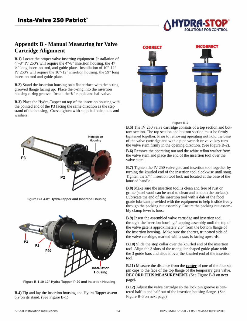
Appendix B - Manual Measuring for Valve Cartridge AlignmentB.1) Locate the proper valve inserting equipment. Installation of 4”-8” IV 250’s will require the 4”-8” insertion housing, the 47 ½” long insertion tool, and guide plate. Installation of 10”-12” IV 250’s will require the 10”-12” insertion housing, the 59” long insertion tool and guide plate.
B.2) Stand the insertion housing on a fl at surface with the o-ring grooved fl ange facing up. Place the o-ring into the insertion housing o-ring groove. Install the ¾” nipple and ball valve.
B.3) Place the Hydra-Tapper on top of the insertion housing with the pointed end of the P3 facing the same direction as the step stand of the housing, Cross tighten with supplied bolts, nuts and washers.
B.4) Tip and lay the insertion housing and Hydra-Tapper assem-bly on its stand. (See Figure B-1)
B.5) The IV 250 valve cartridge consists of a top section and bot-tom section. The top section and bottom section must be fi rmly tightened together. Prior to removing operating nut hold the base of the valve cartridge and with a pipe wrench or valve key turn the valve stem fi rmly in the opening direction. (See Figure B-2).B.6) Remove the operating nut and the white tefl on washer from the valve stem and place the end of the insertion tool over the valve stem.
B.7) Tighten the IV 250 valve gate and insertion tool together by turning the knurled end of the insertion tool clockwise until snug. Tighten the 3/4” insertion tool lock nut located at the base of the knurled handle.
B.8) Make sure the insertion tool is clean and free of rust or grime (steel wool can be used to clean and smooth the surface). Lubricate the end of the insertion tool with a dab of the food grade lubricant provided with the equipment to help it slide freely through the packing nut assembly. Ensure the packing nut assem-bly clamp lever is loose.
B.9) Insert the assembled valve cartridge and insertion tool through the insertion housing / tapping assembly until the top of the valve gate is approximately 2.5” from the bottom fl ange of the insertion housing. Make sure the shorter, truncated side of the valve cartridge, marked with a star, is facing upwards.
B.10) Slide the stop collar over the knurled end of the insertion tool. Align the 3 slots of the triangular shaped guide plate with the 3 guide bars and slide it over the knurled end of the insertion tool.
B.11) Measure the distance from the center of one of the four set pin caps to the face of the top fl ange of the temporary gate valve. RECORD THIS MEASUREMENT. (See Figure B-3 on next page).
B.12) Adjust the valve cartridge so the lock pin groove is cen-tered half in and half out of the insertion housing fl ange. (See Figure B-5 on next page)
Figure B-1 4-8” Hydra-Tapper and Insertion Housing
Figure B-2
Figure B-1 10-12” Hydra-Tapper, P-20 and Insertion Housing

IV 250 Installation Instructions 25 IV250MAN IV 250 v1.85 Revised 09/12/2016
Set the distance from the top of the packing nut assembly to the bottom of the stop collar equal to the measurement recorded in step 8.11. (See Figure B-4 below).
In most cases, this measurement will be 7.5 inches for 4-8” installations and 4.25” for 10-12” installations.
B.13) Confi rm the valve cartridge lock pin groove is still cen-tered.
B.14) Adjust and align the shorter side of the valve cartridge, which is marked with a star, between between (2) bolt holes accordingly. Make a reference mark on the insertion housing, between the two bolt holes. Slide the guide plate to the stop collar and lock the guide plate clamp lever. (See Figure B-6 below)
B.15) Lubricate the completion plug o-ring with food grade lubri-cant provided with the equipment. DO NOT LUBRICATE WIPE SEALS OR PADDLE.
B.16) Slide valve cartridge and insertion tool assembly into the insertion housing until it seats against the top of the insertion housing.
B.17) Tighten the clamp lever on the packing nut assembly to keep the assembled valve gate and insertion tool in place. Do not use tools to tighten the clamp lever.
B.18) After completion of the “Manual Measuring for Valve Cartridge Alignment” section, refer to Section 8, “Install IV 20 Insertion Equipment” to continue the valve insertion procedure.
Figure B-6
Figure B-5
Figure B-4
Figure B-3

Appendix C IV 250 Valve Body Installation Instructions
© 2017 Hydra-Stop All Rights Reserved. 4-12IV250-VBINSTRUC-09.15.17
IMPORTANT: Read installation instructions COMPLETELY before installing the Insta-Valve 250 Patriot
valve body. Failure to follow installation instructions will void product warranty. Follow local safety
regulations and use personal protection equipment (PPE) as required by national, state and local
regulations.
INSTALLATION INSTRUCTION STEPS
1. Inspect the valve body to ensure no damage has occurred during shipment or storage.
(See Figure 1).
2. Locate valve cartridge and box containing stainless steel mounting hardware. Store in a clean,
safe location.
3. Measure pipe outside diameter where the Insta-Valve 250 Patriot is being installed to ensure the
correct insertion valve is being used.
4. Thoroughly clean the pipe surface with a wire brush where the valve body will be installed to
ensure all loose debris and material is removed. Inspect for flaws, i.e., gouges, protrusions, excessive
corrosion, etc. Irregular surfaces should be avoided to assure maximum gasket sealing.
5. Liberally lubricate top and bottom of pipe and mat and throat gaskets with a soap/water solution.
Ensure branch gasket is adequately lubricated.
6. Mount the top half of the valve body on the pipe in the position required for permanent installation
(See Figure 2). Do not rotate the top half of the valve body after it is positioned on the pipe.
7. Install the bottom half of the valve body over the tapered ends of the mat gasket ensuring they
are flat and smooth against the pipe surface. Visually inspect gasket to ensure tapered ends are not
folded or rolled under themselves.
8. Install stainless steel carriage bolts, washers, and nuts (See Figure 3). Finger tighten nuts, ensuring
gaps between top half and bottom half of the valve body are the same front to back and side to side
within 1/8”. (See Figure 4)
9. Using a torque wrench, tighten nuts in proper pattern. Tightening patterns (Figures 5-7) for each
size valve are on the reverse side of this document. Repeat tightening pattern in no more than
25 ft. lb. increments until recommended torque is reached.
10. Wait 10 minutes to allow the gasket to fully seat then re-tighten bolts to recommended torque
three additional times following the tightening pattern.
4” - 12” Insta-Valve 250 Patriot Valve Body Installation Instructions
Figure 1
Figure 2
Figure 3
Figure 4
Installation instructions and best practices continued on reverse
RECOMMENDED TORQUE:
4” - 8” Insta-Valve 250 Patriot
CI / DI Pipe: 115 ft-lbs.
PVC Pipe: 55 ft-lbs.
AC Pipe: 75 ft-lbs.
10” - 12” Insta-Valve 250 Patriot
CI / DI Pipe: 65 ft-lbs.
PVC Pipe: 55 ft-lbs.
AC Pipe: 60 ft-lbs.

Appendix C IV 250 Valve Body Installation Instructions
Specifi cations subject to change without notice.
11. Check inside of valve body outlet to ensure gasket is properly seated. Ensure
completion plug set pins are flush with I.D. of the flange (See Figure 8).
12. Fill valve body with water. Install test flange. Perform pressure test to ensure a
complete seal between the valve body and pipe (do not use a compressible medium
such as air).
Minimum Test Pressure: 1.5 times the system working pressure
Maximum Test Pressure: 375 psi
13. Remove the test flange.
14. Following the tightening pattern, re-torque carriage bolts to recommended torque
before continuing.
15. Properly block (support) Insta-Valve 250 Patriot valve body and ensure pipe joints are
properly restrained. Proceed with valve insertion operation.
INSTALLATION BEST PRACTICES:• Keep nuts and bolts clean and free of debris.
• Adequately lubricate pipe and Insta-Valve 250 Patriot gaskets with soap/water solution paying special attention to AC pipe. Ensure branch gasket is adequately lubricated. Do not use grease or pipe lubricant.
• Avoid rotating top half of Insta-Valve 250 Patriot once placed on pipe.
• Do not use a powered wrench to tighten nuts. You will gall the bolts and damage the valve.
• Block / support the pipe before installing the tapping ma-chine.
• Ensure all pipe joints are restrained prior to proceeding to valve insertion operation.
• Label valve body with a paint pen or permanent marker with the tightening pattern as a visual reminder of the tightening pattern.
Call Hydra-Stop for Technical Support at 800.538.7867 or visit us on the web at www.hydra-stop.com
Figure 68” Bolt Tightening Pattern
Figure 8
Figure 710” and 12” Bolt Tightening Pattern
Figure 54” - 6” Bolt Tightening Pattern
This product is covered by one or more patents, including U.S. Patent No. 9,644,779.