
Inspection procedure for engine block after hot run
27
Inspection procedure for engine block after hot run Kim Mattans Bachelor’s thesis Industrial Management Vaasa 2010
Transcript of Inspection procedure for engine block after hot run

Inspection procedure for engine block after hot run
Kim Mattans
Bachelor’s thesis
Industrial Management
Vaasa 2010

BACHELOR’S THESIS Author: Kim Mattans Degree Programme: Industrial Management Supervisor: Roger Nylund Title: Inspection procedure for engine block after hot run
____________________________________________________________
Date 20.05.2010 Number of pages 19 Appendices 2 ____________________________________________________________ Summary
This Bachelor’s thesis was made at Technical Service W20 in Runsor, Vaasa.
The task was to compile instructions for measurements and inspections of the
engine block in case of a hot run. Instructions are needed because at this
moment there are no instructions for what is to be done in case of a hot run.
The main goal of the thesis was to compile a service letter that includes all the
information and measurement records that are needed when an inspection of
the engine block is carried out. Methods that was used to do this thesis was to
interview people and study how a inspection of a engine block are done. The
result was an internal service letter that is to be used when a hot run occurs.
_____________________________________________________________ Language: English Key words: inspection, hot run, main bearing, camshaft _____________________________________________________________
Filed at: Tritonia Academic Library, Vaasa

EXAMENSARBETE Författare: Kim Mattans Utbildningsprogram och ort: Produktionsekonomi, Vasa Handledare: Roger Nylund Titel: Inspektionsprocess för motorblock efter varmgång.
____________________________________________________________
Datum 20.05.2010 Sidantal 19 Bilagor 2 ____________________________________________________________ Sammanfattning
Detta examensarbete gjordes vid Technical Service W20 i Runsor, Vasa. Det
gick ut på att sammanställa instruktioner för mätningar och inspektioner av
maskinblocken vid en varmgång. Instruktionerna behövs eftersom det inte i
dagens läge finns några liknande instruktioner till hands ifall en varmgång
sker. Målet med examensbetet var att sammanställa ett servicebrev som
innehåller all information samt mätprotokoll som behövs när en inspektion av
ett motorblock behövs. Metoderna som användes för att göra detta
examensarbete var intervjuvning av folk samt literaturstudier angående om hur
inspektioner av motorblock går till. Resultatet blev ett internt servicebrev som
skall användas ifall en varmgång uppstår.
____________________________________________________________ Språk: Engelska Nyckelord: inspektion, varmgång, ramlager, lager,
kamaxel.
____________________________________________________________
Förvaras: Tritonia vetenskapliga biblioteket, Vasa

TABLE OF CONTENTS
ABSTRACT…………………………………………………………………………………………………..
ABSTRAKT…………………………………………………………………………………………………..
TABLE OF CONTENTS…………………………………………………………………………………..
1 INTRODUCTION........................................................................................................... 1
2 PURPOSE OF THE BACHELOR'S THESIS ................................................................ 2
3 COMPANY ...................................................................................................................... 2
3.1 Services ...........................................................................................................................................3
3.2 Ship Power.....................................................................................................................................3
3.3 Power Plants .................................................................................................................................3
4 REASONS WHY INSTRUCTIONS ARE NEEDED ..................................................... 4
5 REASONS WHY A HOT RUN MIGHT APPEAR........................................................ 4
6 MEASUREMENT TOOLS ............................................................................................. 5
6.1 Geometric measurement – Easy Laser.............................................................................5
6.2 Rotalign ...........................................................................................................................................7
6.3 Rank Taylor Hobson .................................................................................................................7
7 INSPECTION PROCEDURES....................................................................................... 8
7.1 Straightness of the main bearing centre line ................................................................9
7.2 Diameter of the main bearing bores .............................................................................. 11
7.3 Straightness of the camshaft bearing bore ................................................................. 12
7.4 Diameter of the camshaft bore ......................................................................................... 12
8 NON-DESTRUCTIVE TESTING ................................................................................ 13
8.1 Magnetic Particle Inspection (MPI) ................................................................................ 13
8.2 Magnetic Particle Inspection procedure ...................................................................... 13
8.3 Liquid penetrant test ............................................................................................................. 14
8.4 Inspection steps ....................................................................................................................... 14
9 MEASUREMENT RECORDS ...................................................................................... 16

10 SUMMARY ................................................................................................................. 18
LIST OF REFERENCES………………………………………………….…………………………….19
APPENDICES………………………………………………………………………………………………...

1
1 INTRODUCTION
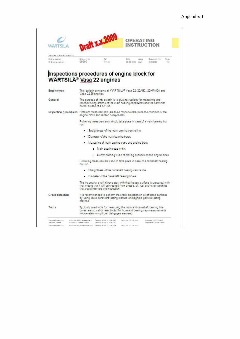
I did my Bachelor's thesis at Wärtsilä Services, Technical Service W20. Mr. Niklas
Donner has supervised my work at Wärtsilä and Mr. Roger Nylund has been my
supervisor at Novia. To work with this Bachelor's thesis about inspection procedures
and reconditioning in case of a hot run in the engine block has been very interesting.
The main goal of the thesis was to compile a service letter that includes all the
information and measurements that are needed when an inspection of the engine block
is to be performed. The service letter includes all the Vasa 22 engines. The service
letter is an internal document so therefore it will not be added as an appendix but a
screenshot of the first page can be found in appendix 1.

2
2 PURPOSE OF THE BACHELOR'S THESIS
The purpose of this Bachelor's thesis was to compile instructions for measuring and
reconditioning actions regarding the main bearing caps/bores and the camshaft bores
in case of a hot run. The assignment also included to make new measurement records
because the old ones did not include all the different tolerances for each engine. There
are two different kinds of tools that are used when the diameter and the straightness of
the main bearing caps and the camshaft bearings are being measured, the laser
measurement tools and the optical measurement tools. To find cracks and defects on
the main bearing caps there are two different methods that might be used, either
magnetic particle inspection or liquid penetrant inspection. These two ways to find
cracks and defects are called non-destructive testing.
3 COMPANY
Wärtsilä was founded in 1834 in the municipality of Tohmajärvi in eastern Finland. In
1936 Wärtsilä was established in Vaasa. In 1954 the first manufacturing of diesel
engines started. Wärtsilä has more than 18.000 employees and they have operations in
160 locations in 70 countries all around the world. There are more than 3000
employees in Finland and they are stationed in Vaasa, Turku, Raisio, Helsinki, Espoo
and Kiuruvesi. /7/
Wärtsilä in Finland is both a ship power supplier for all types of marine and offshore
applications and a provider of power plants in the decentralized energy market. The
global service network provides service, maintenance and reconditioning solutions
both for machinery and power plants throughout the lifetime of the installations.
Wärtsilä’s main export areas are Europe, Asia and America. Five different engines are
manufactured in Vaasa: W20, W32, W34DF, W34SG and Wärtsilä Auxpac. /7/
3
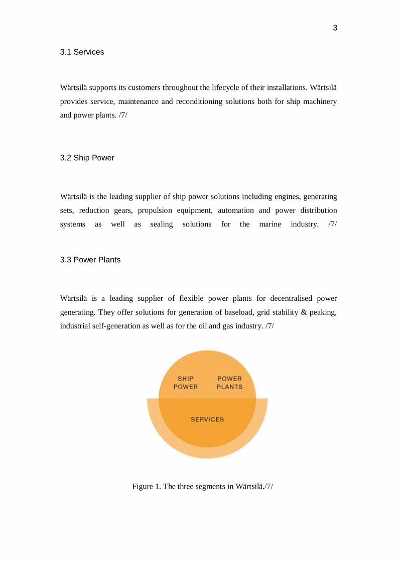
3.1 Services
Wärtsilä supports its customers throughout the lifecycle of their installations. Wärtsilä
provides service, maintenance and reconditioning solutions both for ship machinery
and power plants. /7/
3.2 Ship Power
Wärtsilä is the leading supplier of ship power solutions including engines, generating
sets, reduction gears, propulsion equipment, automation and power distribution
systems as well as sealing solutions for the marine industry. /7/
3.3 Power Plants
Wärtsilä is a leading supplier of flexible power plants for decentralised power
generating. They offer solutions for generation of baseload, grid stability & peaking,
industrial self-generation as well as for the oil and gas industry. /7/
Figure 1. The three segments in Wärtsilä./7/

4
4 REASONS WHY INSTRUCTIONS ARE NEEDED
Instructions are needed because at this moment there are no existing instructions for
what is to be inspected on any engine type. Instructions for measurements and
reconditioning of the main bearing caps/bores and the camshaft bores are needed
when a hot run has occurred on an engine block. The purpose of the instructions is
that one should be able to find the instruction and the needed measurement records
easily on the internal bulletin board. In the instructions, the tolerances for the main
bearing bore and the camshaft bearing bore for each Vasa 22 type are listed. In the
instructions the drawing numbers for the new measurement records are listed to make
it easy to obtain the different measurement records that might be needed. This will
simplify and speed up the work. In the old measurement records there were not all the
tolerances and dimensions that are needed when a measurement is to be made. The
workers that took the measurements had to start by searching for all the tolerances and
dimensions in different drawings and thereafter proceed with the work.
5 REASONS WHY A HOT RUN MIGHT APPEAR
The most common reason why a hot run occurs is that the lubrication oil in the engine
system is bad. There are several reasons why a hot run might appear and the most
common ones have been listed below.
- Bad lubrication oil in the system
- A lot of particles in the oil
- Metal to metal wear
- The bearings have been wrongly installed
- The service on the engines has not been done as it should.

5
6 MEASUREMENT TOOLS
There are different kinds of measurement tools on the market such as laser tools,
optical tools, dial gauges and non-destructive testing apparatus. These are the ones
that have been dealt with in this bulletin and thesis. The laser tool brands that are used
in Wärtsilä are Easy Laser and Rotalign. The Easy Laser is used at the product factory
after the main bearings have been mounted onto the engine block. The Rotalign is a
recently bought laser tool that is to be used at Service in case they will have to travel
to a ship to investigate the hot run on an engine block. The dial gauges are used to
measure the diameters of the main bearing bores and the camshaft bearing bores.
The optical measurement tool brand is Rank Taylor Hobson. Today the laser tools are
much more commonly used in Wärtsilä at least at the product factory. But when for
example the service department sends out some of the fitters to check the engine
block it is good if the fitters are familiar with both the laser and the optical tools.
Non-destructive testing apparatus is used to inspect if the main bearing caps and
camshaft bearings have cracks or defects that are not visible to the naked eye.
6.1 Geometric measurement – Easy Laser
Easy Laser is a measurement tool that is used for measurements of the straightness of
the bores and bearing journals in diesel engines. See Figure 2, page 6, for an example
of the camshaft and crankshaft bearings. It measures both full and half bearing
positions. The resolution is 0.001 mm [0.05 mils]. This measurement tool can be used
both in a product factory and out in the fields. /1/
Bores from 100 mm to 500 mm [3.9”-19.7"] can be measured with the standard
system. The distance that can be measured is up to 40 m [132 feet.]. The system
automatically calculates the bores’ positions in relation to each other both horizontally
and vertically. Measurement points can be added, removed or re-measured at any time
during the measurement process. /1/

6
The Easy Laser is used in the product factory to measure the straightness of the
camshaft bores and crankshaft bores (See figure 2). In the product factory in Runsor,
Vaasa W20, they have developed different flanges for the detector depending on what
they are measuring. There are different flanges for the camshaft bore and the main
bearing bore. Also for the laser transmitter there has been developed a flange that can
be assembled on both the camshaft and the main bearing journal.
Figure 2. Straightness measurements
The following parts must be available when the measuring with Easy-Laser starts
Laser transmitter
Detector
Display unit
Cable with push/pull connectors.
The following parts are optional
User manual
Computer/printer.

7
6.2 Rotalign
The Rotalign is like the Easy Laser a laser measurement tool that is used to measure
the straightness of bores. CENTRALIGN Ultra (See picture 1) is a precision laser
alignment system designed to replace older and more time-consuming technologies. It
is much faster, very precise, and provides a clear measurement record. The Rotalign
can measure diameters from 45 mm to 4000 mm. It is possible to measure both
magnetic and non-magnetic bores. It is easy to set the CENTRALIGN apparatus to
different diameters on the main bearing bores. /5/the intention is that the Rotalign
Ultra is to be used when Field Service sends out their fitters to do an inspection of
some engine.
Picture 1. The Rotalign display unit.
6.3 Rank Taylor Hobson
The alignment telescope is used to set and check alignment, squareness, straightness,
flatness, parallelism, vertically and level. The telescope generates a straight line. This
forms the basic reference from which all measurements are taken. (See figure 3, page
8).
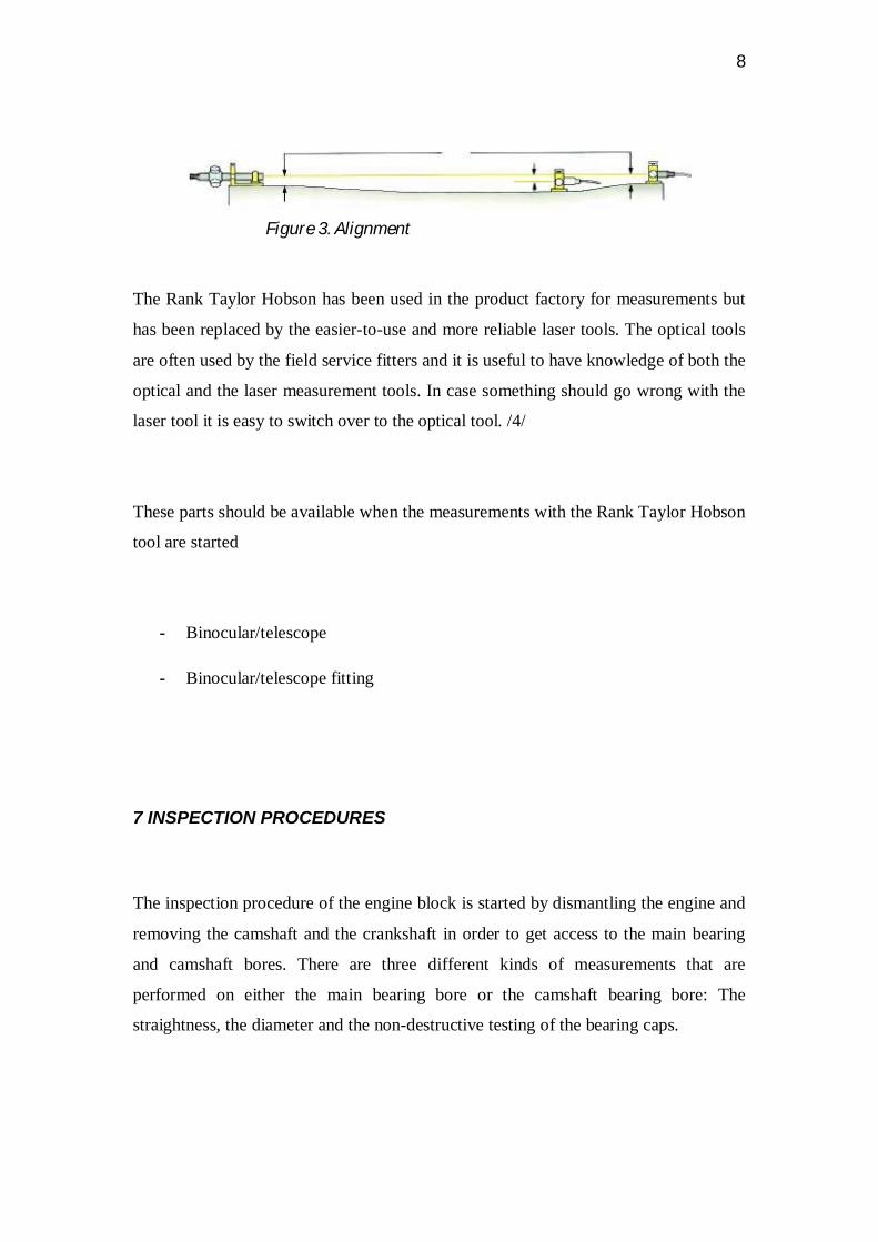
8
Figure 3. Alignment
The Rank Taylor Hobson has been used in the product factory for measurements but
has been replaced by the easier-to-use and more reliable laser tools. The optical tools
are often used by the field service fitters and it is useful to have knowledge of both the
optical and the laser measurement tools. In case something should go wrong with the
laser tool it is easy to switch over to the optical tool. /4/
These parts should be available when the measurements with the Rank Taylor Hobson
tool are started
- Binocular/telescope
- Binocular/telescope fitting
7 INSPECTION PROCEDURES
The inspection procedure of the engine block is started by dismantling the engine and
removing the camshaft and the crankshaft in order to get access to the main bearing
and camshaft bores. There are three different kinds of measurements that are
performed on either the main bearing bore or the camshaft bearing bore: The
straightness, the diameter and the non-destructive testing of the bearing caps.

9
7.1 Straightness of the main bearing centre line
The straightness of the main bearing centre line is either measured by means of a laser
measurement tool or an optical measurement tool.
1. Transmitter
Step 1 is to attach the laser transmitter to the first main bearing bore at the flywheel
end (picture 2 bellow) and to check that the transmitter is in the right position and
level.
Picture 2. The first step in the inspection procedure
2. Detector
Step 2 is to connect the detector to the display unit (See pictures 3 and 4, pages 10 and
11). Step 3 is to calibrate the measurement tool, step 4 is to put the detector in the first
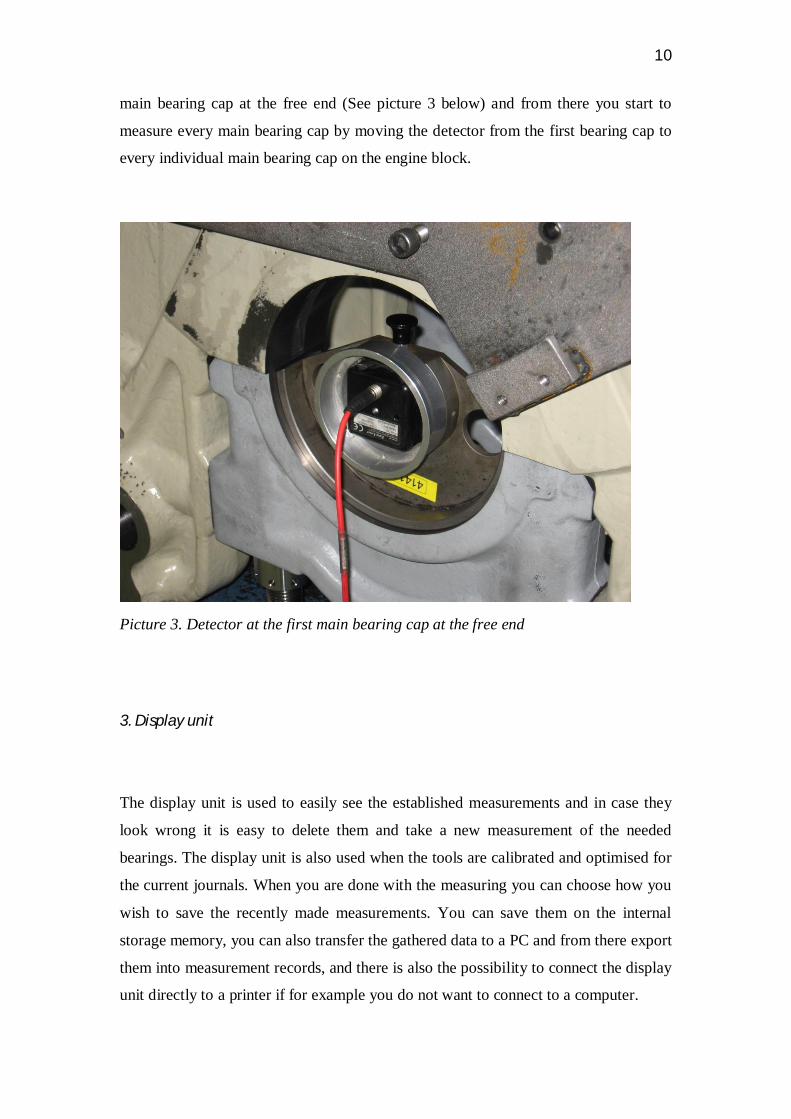
10
main bearing cap at the free end (See picture 3 below) and from there you start to
measure every main bearing cap by moving the detector from the first bearing cap to
every individual main bearing cap on the engine block.
Picture 3. Detector at the first main bearing cap at the free end
3. Display unit
The display unit is used to easily see the established measurements and in case they
look wrong it is easy to delete them and take a new measurement of the needed
bearings. The display unit is also used when the tools are calibrated and optimised for
the current journals. When you are done with the measuring you can choose how you
wish to save the recently made measurements. You can save them on the internal
storage memory, you can also transfer the gathered data to a PC and from there export
them into measurement records, and there is also the possibility to connect the display
unit directly to a printer if for example you do not want to connect to a computer.

11
Picture 4. The display unit
7.2 Diameter of the main bearing bores
The diameters for the main bearing bores are measured with dial gauges (See picture
5 below). The first thing to be done before any measurements with dial gauges are
performed is to calibrate the dial gauge towards a calibrating tool. The dial gauge is
moved back and forth (Figure 4, page 12) when measuring and from that you can see
if the measurements are within the tolerances for the specific part.
Picture 5. Dial gauge

12
Figure 4. How the dial gauge is used/6/
7.3 Straightness of the camshaft bearing bore
The inspection procedure for measuring the straightness of the camshaft bearing
centre line is the same as for the main bearing bore. The only difference is that the
flanges are exchanged for different kinds that are manufactured to fit into the
camshaft bore. The flange that is used on the laser transmitter can be used for both the
camshaft and the main bearing bore.
7.4 Diameter of the camshaft bore
The inspection procedure for measuring the diameter of camshaft bearing bores is the
same as the inspection procedure for the main bearing bores.

13
8 NON-DESTRUCTIVE TESTING
Non-destructive testing (NDT) means to check the material or component without
causing any damage. The most common NDT methods are ultrasonic, magnetic
particle, liquid particle and radiographic. The magnetic particle and liquid particle
tests are used in Wärtsilä to detect cracks in the material that are not visible to the
naked eye.
8.1 Magnetic Particle Inspection (MPI)
Magnetic particle inspection is a method for locating cracks and surface defects in
magnetic materials. The magnetic particle inspection can be applied only to
ferromagnetic materials like construction steels, cast irons and spring steels. It cannot
be applied to for example inlet/exhaust valves and Cu-pipes. /3/
8.2 Magnetic Particle Inspection procedure
The magnetic particle inspection always starts with the following procedure.
1. Start by cleaning the part that is to be inspected from rust, oil, grease or other
things that are not meant to be there.
2. The second thing is to establish a magnetic field in the part.
3. When the part has been magnetized the part should be sprayed with the test
medium (for approximately 5 sec.)
4. After the parts have been sprayed, the magnetic field should be turned off.
5. The part is then de-magnetized.
6. The surface is then visually evaluated for defect indications.
7. The indications are documented.
8. The part is either accepted or rejected./3/

14
8.3 Liquid penetrant test
Liquid penetrant test (LPI), also called dye penetrant test (DPI), is a widely applied
and low-cost inspection method used to locate surface-breaking defects in all non-
porous materials (metals, plastics...). LPI is used to detect casting and forging defects,
cracks and leaks in new products, and fatigue cracks on in-service components. /2/
8.4 Inspection steps
1. Pre-cleaning
The test surface is first cleaned to remove dirt, paint, oil, grease or any loose scale that
could either keep the penetrant out of a defect, or cause irrelevant or false indication.
Cleaning methods may include solvents, alkaline cleaning steps, vapor degreasing or
media blasting. The end goal of this step is a clean surface where any defects present
are open to the surface, dry and free of contamination./2/
2. Application of penetrant
The penetrant is then added to the surface of the item that is being tested. The
penetrant is then left to soak into any possible flaws. It generally takes about 5-30
minutes for the penetrant to soak into the material. The soak time depends mainly on
the material that is being tested and the size of the flaws. Smaller flaws require a
longer penetration time. /2/
3. Excess Penetrant Removal
The overflow of penetrant is then removed from the part’s surface. The removal
method depends on what type of penetrant that has been used. Water-washable,
solvent-removable, lipophilic post-emulsifiable or hydrophilic post-emulsifiable are
the most common choices. If you are using a solver remover and a lint-free cloth it is

15
very important that you do not spray the solvent directly on the surface because this
might remove the penetrant from the flaws. /2/
4. Application of developer
After that the overflow of penetrant has been removed from the surface of the material
a white developer is applied to the sample. The developer draws penetrant from
defects out onto the surface to form a visible indication. Any colored stains indicate
the positions and types of defects on the surface under inspection. /2/
5. Inspection
The inspector will use visible light with adequate intensity for visible dye penetrant.
Ultraviolet (UV-A) radiation of adequate intensity (1W per centimetre squared is
common), along with low ambient light levels for fluorescent penetrant examinations.
Inspection of the test surface should take place after a 10 minute development time.
This time delay allows the blotting action to occur. The inspector may observe the
sample for indication formation when using visible dye, but this should not be done
when using a fluorescent penetrant. Also of concern, if one waits too long after
development, the indications may "bleed out" so that interpretation is hindered. /2/
6. Recording of the measurements
After that the inspection has been performed the information from the test shall be
gathered in some form of record./2/
7. Post cleaning
After an inspection the surface is often cleaned. As a final post-cleaning process, the
developer coating can be removed with water, an air-liquid mixture, or in a liquid
solvent immersion tank. Special care should be taken with materials that must be
protected from corrosion /2/
16
9 MEASUREMENT RECORDS
All measurements that are gathered during a measurement of the main bearings and
the camshaft bearings should be documented in a measurement record. A
measurement record is a really important certificate and a document that is to give
information about the measured object’s dimensions and tolerances.
In addition to the result of the measurement the following information should also be
found in the measurement record:
Engine type
Engine No.
Installation (When measurement records are done on a ship)
Dates and locality
The name of the person who performed the measurements
Temperature
Component drawing number
Engine running hour/ component running hour
In the measurement records for the alignment of the main bearing caps and for the
camshaft bearing caps there is a table where the information gathered from the
measurement is shown and from there you can see how the x-line and y-line are
presented. From this it is very easy to see if the straightness of the bearings is within
the tolerances. But just because the measurement is within the tolerances it is not
certain that it is approved because if every single bearing is jumping from for example
10 to -10 (if the approved tolerances are for example ± 10) it is not really good
because in that case the main bearing bore is quite crooked.

17
Figure 5. Good measurement
Figure 6. Bad measurement

18
10 SUMMARY
This work was really interesting and instructive. I have learned a lot about how to act
when a hot run occurs on an engine, I have learned how the measurements are made
and the difference between the various measurement tools. I have also acquired a lot
of knowledge of the main bearing system. I have studied and gathered information
from drawings and I have drawn a repair drawing in UGS NX 6.0.
I spent some time in the product factory to see how the measurements are made in
real life, and I went for a 2-day course at Wärtsilä in how to use the new measurement
tools that Field Service has acquired.
When I started with this Bachelor's thesis my knowledge about this subject was
limited so I had to start by familiarizing myself with the work by studying some
similar instructions and by studying the different measurement methods and the main
bearings. During this work I have learned a lot about the things I have mentioned in
this text but also a lot about other aspects of the engine.
Finally I would like to thank Wärtsilä for giving me the opportunity to do my
Bachelor's thesis. I also wish to thank Mr. Niklas Donner, Mr. Curt-Erik Lindqvist at
Technical Service and all the other people involved, including my supervisor Roger
Nylund at Novia, for their help to make this work possible.

19
LIST OF REFERENCES /1/ Easy Laser’s Homepage www.damalini.fi (Read 01.12.2009 – 15.04.2010) /2/ Liquid penetrant test Liquid penetrant test PowerPoint Wärtsilä Intranet pages (Read 24.03.2010) /3/ Magnetic particle test Magnetic particle test PowerPoint Wärtsilä Intranet pages (Read 24.03.2010) /4/ Rank Taylor Hobson’s homepage www.taylor-hobson.com (Read 07.01.2010 – 15.02.2010) /5/ Rotalign’s homepage www.pruftechnik.com/ (Read 07.01.2010 – 15.02.2010) /6/ Sved Holger Mätteknikkompendium Novia University of applied sciences Intranet pages (Read 08.02.2010) /7/ Wärtsilä’s homepage www.wärtsilä.fi (Read 15.12.2009)

APPENDICES
Appendix 1 - Picture of the Service Letter
Appendix 2 - 3D picture of an engine block
Appendix 1

Appendix 2