Input/Output and Storage Objectives Systems - University...
24
1 Input/Output and Storage Input/Output and Storage Systems Systems CS 2401 Comp. Org. & Assembly Input/Output and Storage Systems -- Chapter 7 1 Objectives Objectives Understand how I/O systems work, including I/O methods and architectures including I/O methods and architectures. Become familiar with storage media, and the differences in their respective formats. Understand how RAID improves disk performance and reliability. Become familiar with the concepts of data d l bl f CS 2401 Comp. Org. & Assembly Input/Output and Storage Systems -- Chapter 7 2 compression and applications suitable for each type of compression algorithm. 7.1 Introduction 7.1 Introduction Data storage and retrieval is one of the primary functions of computer systems primary functions of computer systems. One could easily make the argument that computers are more useful to us as data storage and retrieval devices than they are as computational machines. All computers have I/O devices connected to them, and to achieve good performance I/O should be kept to a minimum! CS 2401 Comp. Org. & Assembly Input/Output and Storage Systems -- Chapter 7 3 In studying I/O, we seek to understand the different types of I/O devices as well as how they work. 7.2 I/O and Performance 7.2 I/O and Performance Sluggish I/O throughput can have a ripple effect dragging down overall system effect, dragging down overall system performance. This is especially true when virtual memory is involved. The fastest processor in the world is of little use if it spends most of its time waiting for data. CS 2401 Comp. Org. & Assembly Input/Output and Storage Systems -- Chapter 7 4 data. If we really understand what’s happening in a computer system we can make the best possible use of its resources.
Transcript of Input/Output and Storage Objectives Systems - University...

1
Input/Output and Storage Input/Output and Storage SystemsSystemsyy
CS 2401 Comp. Org. & Assembly
Input/Output and Storage Systems -- Chapter 7
1
ObjectivesObjectivesUnderstand how I/O systems work, including I/O methods and architecturesincluding I/O methods and architectures.Become familiar with storage media, and the differences in their respective formats.Understand how RAID improves disk performance and reliability.Become familiar with the concepts of data
d l bl f
CS 2401 Comp. Org. & Assembly
Input/Output and Storage Systems -- Chapter 7
2
compression and applications suitable for each type of compression algorithm.
7.1 Introduction7.1 IntroductionData storage and retrieval is one of the primary functions of computer systems primary functions of computer systems.
One could easily make the argument that computers are more useful to us as data storage and retrieval devices than they are as computational machines.
All computers have I/O devices connected to them, and to achieve good performance I/O should be kept to a minimum!
CS 2401 Comp. Org. & Assembly
Input/Output and Storage Systems -- Chapter 7
3
In studying I/O, we seek to understand the different types of I/O devices as well as how they work.
7.2 I/O and Performance7.2 I/O and PerformanceSluggish I/O throughput can have a ripple effect dragging down overall system effect, dragging down overall system performance.
This is especially true when virtual memory is involved.
The fastest processor in the world is of little use if it spends most of its time waiting for data.
CS 2401 Comp. Org. & Assembly
Input/Output and Storage Systems -- Chapter 7
4
data.If we really understand what’s happening in a computer system we can make the best possible use of its resources.

2
7.3 Amdahl’s Law7.3 Amdahl’s LawThe overall performance of a system is a result of the interaction of all of its components.pSystem performance is most effectively improved when the performance of the most heavily used components is improved. This idea is quantified by Amdahl’s Law:
where
CS 2401 Comp. Org. & Assembly
Input/Output and Storage Systems -- Chapter 7
5
S is the overall speedupf is the fraction of work performed by
a faster component k is the speedup of a faster component.
7.3 Amdahl’s Law7.3 Amdahl’s LawAmdahl’s Law gives us a handy way to estimate the performance improvement we can expect when we performance improvement we can expect when we upgrade a system component.Example: On a large system,
suppose we can upgrade a CPU to make it 50% faster for $10,000 or upgrade its disk drives for $7,000 to make them 2.5 times faster (250% faster). Processes spend 70% of their time running in the CPU and 30% of their time waiting for disk service.
CS 2401 Comp. Org. & Assembly
Input/Output and Storage Systems -- Chapter 7
6
An upgrade of which component would offer the greater benefit for the lesser cost?
7.3 Amdahl’s Law7.3 Amdahl’s LawThe processor option offers a 130% speedup:
And the disk drive option gives a 122% speedup:
CS 2401 Comp. Org. & Assembly
Input/Output and Storage Systems -- Chapter 7
7
Each 1% of improvement for the processor costs $333, and for the disk a 1% improvement costs $318.
Should price/performance be your only concern? Should price/performance be your only concern?
7.3 Amdahl’s 7.3 Amdahl’s LawLaw2. (page 381) Suppose the daytime processing load
consists of 60% CPU activity and 40% disk activity. y yYour customers are complaining that the system is slow. After doing some research, you have learned that you can upgrade your disks for $8,000 to make them 2.5 times as fast as they are currently. You have also learned that you can upgrade your CPU to make it 1.4 as fast for $5,000.a. Which would you choose to yield the best performance
improvement for the least amount of money?b. Which option would you choose if you don't care about the p y y
money, but want a faster system?c. What is the break-even point for the upgrades? That is,
what price would we need to charge for the CPU (or the disk – change only one) so the result was the same cost per 1% increase for both?
CS 2401 Comp. Org. & Assembly
Input/Output and Storage Systems -- Chapter 7
8

3
7.4 I/O Architectures7.4 I/O ArchitecturesWe define input/output as a subsystem of components that moves coded data between external components that moves coded data between external devices and a host system (CPU, main memory).I/O subsystems include:
Blocks of main memory that are devoted to I/O functions.Buses that move data into and out of the system. Control modules in the host and in peripheral devicesInterfaces to external components such as keyboards
CS 2401 Comp. Org. & Assembly
Input/Output and Storage Systems -- Chapter 7
9
Interfaces to external components such as keyboards and disks.Cabling or communications links between the host system and its peripherals.
7.4 Model I/O Configuration7.4 Model I/O Configuration
CS 2401 Comp. Org. & Assembly
Input/Output and Storage Systems -- Chapter 7
10
7.4.1 I/O Control Methods7.4.1 I/O Control MethodsI/O can be controlled in four general ways.
1. Programmed I/O reserves a register for each I/O device. Each register is continually polled to detect data arrival.
2. Interrupt-Driven I/O allows the CPU to do other things until I/O is requested.
3. Direct Memory Access (DMA) offloads I/O processing to a special purpose chip that takes
CS 2401 Comp. Org. & Assembly
Input/Output and Storage Systems -- Chapter 7
11
processing to a special-purpose chip that takes care of the details.
4. Channel I/O uses dedicated I/O processors.
7.4.1 Programmed (Polled) I/O7.4.1 Programmed (Polled) I/OReserves a register for each I/O devicePolling -- CPU continually monitors each register waiting for g y g gdataIf data ready condition is true, CPU processes the dataPros:
We have programmatic control over the behavior of each I/O deviceAdjustments can be made to the number and types of devices, polling priorities and intervals.
Con:Constant register polling -- CPU is in a busy wait state
CS 2401 Comp. Org. & Assembly
Input/Output and Storage Systems -- Chapter 7
12
g p g yHow often to poll
Best suited for special-purpose systemsAutomated teller machines and systemsMonitoring or control systems

4
7.4.1 Interrupt7.4.1 Interrupt--Driven I/ODriven I/OThis is an idealized I/O subsystem that uses interruptsinterrupts.Each device connects its interrupt line to the interrupt controller.
The controller signals the CPU when any of the
CS 2401 Comp. Org. & Assembly
Input/Output and Storage Systems -- Chapter 7
13
when any of the interrupt lines are asserted.
7.4.1 Interrupt7.4.1 Interrupt--Driven I/ODriven I/ORecall from Chapter 4 that in a system that uses interrupts the status of the interrupt uses interrupts, the status of the interrupt signal is checked at the top of the fetch-decode-execute cycle.The particular code that is executed whenever an interrupt occurs is determined by a set of addresses called interrupt vectors that are stored in low memory
CS 2401 Comp. Org. & Assembly
Input/Output and Storage Systems -- Chapter 7
14
vectors that are stored in low memory.The system state is saved before the interrupt service routine is executed and is restored afterward.
7.4.1 Interrupt7.4.1 Interrupt--Driven I/ODriven I/OI/O device send a request (interrupt) to CPU for servicingInterrupt flag – a bit in the flag register to signal to CPUInterrupt vectors – service routinesService routines can be modified
CS 2401 Comp. Org. & Assembly
Input/Output and Storage Systems -- Chapter 7
15
Service routines can be modified.
CS 2401 Comp. Org. & Assembly
Input/Output and Storage Systems -- Chapter 7
16
The Fetch-Decode-Interrupt Cycle with Interrupt Checking Processing an Interrupt

5
7.4.1 Direct Memory Access (DMA)7.4.1 Direct Memory Access (DMA)Notice that the DMA and the CPU share and the CPU share the bus. CPU provides DMA with location of the bytes, # bytes to be transferred, destination device or memory address
CS 2401 Comp. Org. & Assembly
Input/Output and Storage Systems -- Chapter 7
17
yThe DMA runs at a higher priority and steals memory cycles from the CPU.
7.4.1 Direct Memory Access (DMA)7.4.1 Direct Memory Access (DMA)WHILE More – input AND NOT Error
ADD 1 TO Byte-countADD 1 TO Byte countIF Byte-count > Total-bytes-to-be-transferred THEN
EXITENDIFPlace byte in destination bufferRaise Byte-ready signalInitialize timerREPEAT
WAITUNTIL Byte-acknowledged, Timeout, OR Error
ENDWHILE
CS 2401 Comp. Org. & Assembly
Input/Output and Storage Systems -- Chapter 7
18
7.4.1 Direct Memory Access (DMA)7.4.1 Direct Memory Access (DMA)
CS 2401 Comp. Org. & Assembly
Input/Output and Storage Systems -- Chapter 7
19
7.4.1 Channel I/O7.4.1 Channel I/OVery large systems employ channel I/O.Channel I/O consists of one or more I/O Channel I/O consists of one or more I/O processors (IOPs) that control various channel paths.Slower devices such as terminals and printers are combined (multiplexed) into a single faster channel.On IBM mainframes, multiplexed channels
ll d l l h l h f
CS 2401 Comp. Org. & Assembly
Input/Output and Storage Systems -- Chapter 7
20
are called multiplexor channels, the faster ones are called selector channels.

6
7.4.1 Channel I/O7.4.1 Channel I/OChannel I/O is distinguished from DMA by the intelligence of the IOPsthe intelligence of the IOPs.The IOP negotiates protocols, issues device commands, translates storage coding to memory coding, and can transfer entire files or groups of files independent of the host CPU. The host has only to create the program
CS 2401 Comp. Org. & Assembly
Input/Output and Storage Systems -- Chapter 7
21
The host has only to create the program instructions for the I/O operation and tell the IOP where to find them.
7.4.1 Channel I/O Configuration7.4.1 Channel I/O Configuration
CS 2401 Comp. Org. & Assembly
Input/Output and Storage Systems -- Chapter 7
22
7.4.2 Character I/O Versus 7.4.2 Character I/O Versus Block I/OBlock I/O
Character I/O devices process one byte (or character) at a timecharacter) at a time.
Examples include modems, keyboards, and mice.Keyboards are usually connected through an interrupt-driven I/O system.
Block I/O devices handle bytes in groups.Most mass storage devices (disk and tape)
CS 2401 Comp. Org. & Assembly
Input/Output and Storage Systems -- Chapter 7
23
Most mass storage devices (disk and tape) are block I/O devices.Block I/O systems are most efficiently connected through DMA or channel I/O.
7.4.3 I/O Bus Operations7.4.3 I/O Bus OperationsI/O buses, unlike memory buses, operate asynchronously. Requests for bus access must be asynchronously. Requests for bus access must be arbitrated among the devices involved.Bus control lines activate the devices when they are needed, raise signals when errors have occurred, and reset devices when necessary.The number of data lines is the width of the bus.A bus clock coordinates activities and provides bit cell boundaries.
CS 2401 Comp. Org. & Assembly
Input/Output and Storage Systems -- Chapter 7
24

7
7.4.3 System Bus7.4.3 System Bus
CS 2401 Comp. Org. & Assembly
Input/Output and Storage Systems -- Chapter 7
25
7.4.3 System Bus7.4.3 System Bus
This is a generic DMA configuration showing how the DMA circuit connects to a data bus.
CS 2401 Comp. Org. & Assembly
Input/Output and Storage Systems -- Chapter 7
26
7.4.3 I/O Bus Connections7.4.3 I/O Bus Connections
CS 2401 Comp. Org. & Assembly
Input/Output and Storage Systems -- Chapter 7
27
7.4.3 Write Data to Disk7.4.3 Write Data to Disk1. The DMA circuit places the address of the disk controller on the
address lines, and raises (asserts) the Request and Writesignalssignals.
2. With the Request signal asserted, decoder circuits in the controller interrogate the address lines.
3. Upon sensing its own address, the decoder enables the disk control circuits. If the disk is available for writing data, the controller asserts a signal on the Ready line. At this point, the handshake between the DMA and the controller is complete. With the Ready signal raised, no other devices may use the bus.
4. The DMA circuits then place the data on the lines and lower the Request signal.
5 When the disk controller sees the Request signal drop it transfer
CS 2401 Comp. Org. & Assembly
Input/Output and Storage Systems -- Chapter 7
28
5. When the disk controller sees the Request signal drop, it transfer the byte from data lines to the disk buffer, and then lowers its Ready signal.

8
7.4.3 Bus Timing Diagram7.4.3 Bus Timing DiagramTiming diagrams define bus operation in detail.
CS 2401 Comp. Org. & Assembly
Input/Output and Storage Systems -- Chapter 7
29
7.5 Data Transmission Modes7.5 Data Transmission ModesBytes can be conveyed from one point to panother by sending their encoding signals simultaneously using parallel data transmission or by sending them one bit at a time in serial data transmission
P ll l d t
CS 2401 Comp. Org. & Assembly
Input/Output and Storage Systems -- Chapter 7
30
Parallel data transmission for a printer resembles the signal protocol of a memory bus:
7.5 Data Transmission Modes7.5 Data Transmission ModesIn parallel data transmission, the interface
i d f h birequires one conductor for each bit.Parallel cables are fatter than serial cables.Compared with parallel data interfaces, serial communications interfaces:
Require fewer conductors.Are less susceptible to attenuation
CS 2401 Comp. Org. & Assembly
Input/Output and Storage Systems -- Chapter 7
31
Are less susceptible to attenuation.Can transmit data farther and faster.
Serial communications interfaces are suitable for time-sensitive (isochronous) data such as voice and video.Serial communications interfaces are suitable for time-sensitive (isochronous) data such as voice and video.
7.6 Magnetic Disk Technology7.6 Magnetic Disk TechnologyMagnetic disks offer large amounts of durable storage that can be accessed durable storage that can be accessed quickly.Disk drives are called random (or direct) access storage devices, because blocks of data can be accessed according to their location on the disk.
This term was coined when all other durable
CS 2401 Comp. Org. & Assembly
Input/Output and Storage Systems -- Chapter 7
32
This term was coined when all other durable storage (e.g., tape) was sequential.
Magnetic disk organization is shown on the following slide.

9
7.6 Magnetic Disk Technology7.6 Magnetic Disk TechnologyDisk tracks are
b d f h numbered from the outside edge, starting with zero.
CS 2401 Comp. Org. & Assembly
Input/Output and Storage Systems -- Chapter 7
33
7.6.1 Rigid Disk Drives7.6.1 Rigid Disk DrivesHard disk platters are mounted on spindles.pRead/write heads are mounted on a comb that swings radially to read the disk. The rotating disk forms a logical cylinder beneath the read/write heads.
CS 2401 Comp. Org. & Assembly
Input/Output and Storage Systems -- Chapter 7
34
Data blocks are addressed by their cylinder, surface, and sector.
7.6.1 Rigid Disk Drives7.6.1 Rigid Disk DrivesThere are a number of electromechanical properties of hard disk drives that properties of hard disk drives that determine how fast its data can be accessed.Seek time is the time that it takes for a disk arm to move into position over the desired cylinder.Rotational delay is the time that it takes for the desired sector to move into position
CS 2401 Comp. Org. & Assembly
Input/Output and Storage Systems -- Chapter 7
35
the desired sector to move into position beneath the read/write head.Seek time + rotational delay = access time.
7.6.1 Rigid Disk Drives7.6.1 Rigid Disk DrivesTransfer rate gives us the rate at which data can be read from the disk.read from the disk.Average latency is a function of the rotational speed:
Mean Time To Failure (MTTF) is a statistically-determined value often calculated experimentally
CS 2401 Comp. Org. & Assembly
Input/Output and Storage Systems -- Chapter 7
36
determined value often calculated experimentally.It usually doesn’t tell us much about the actual expected life of the disk. Design life is usually more realistic.
10
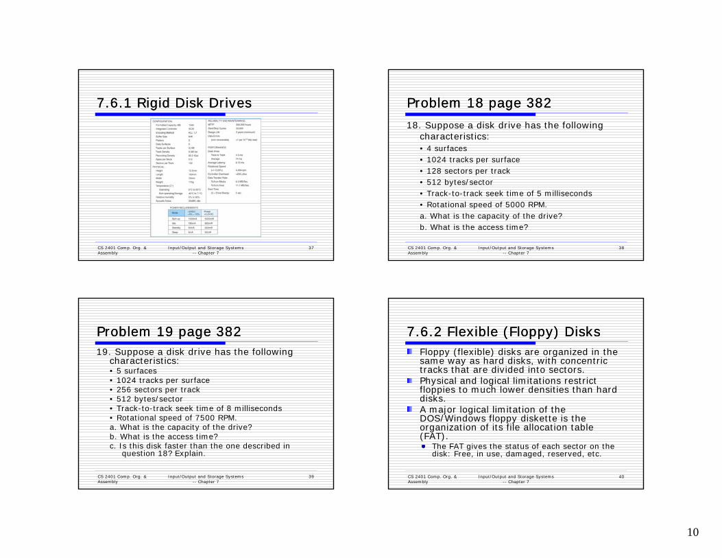
7.6.1 Rigid Disk Drives7.6.1 Rigid Disk Drives
CS 2401 Comp. Org. & Assembly
Input/Output and Storage Systems -- Chapter 7
37
Problem 18 page 382Problem 18 page 38218. Suppose a disk drive has the following
h i icharacteristics:• 4 surfaces• 1024 tracks per surface• 128 sectors per track• 512 bytes/sector• Track-to-track seek time of 5 milliseconds
CS 2401 Comp. Org. & Assembly
Input/Output and Storage Systems -- Chapter 7
38
• Rotational speed of 5000 RPM.a. What is the capacity of the drive?b. What is the access time?
Problem 19 page 382Problem 19 page 38219. Suppose a disk drive has the following
characteristics:characteristics:• 5 surfaces• 1024 tracks per surface• 256 sectors per track• 512 bytes/sector• Track-to-track seek time of 8 milliseconds• Rotational speed of 7500 RPM.a What is the capacity of the drive?
CS 2401 Comp. Org. & Assembly
Input/Output and Storage Systems -- Chapter 7
39
a. What is the capacity of the drive?b. What is the access time?c. Is this disk faster than the one described in
question 18? Explain.
7.6.2 Flexible (Floppy) Disks7.6.2 Flexible (Floppy) DisksFloppy (flexible) disks are organized in the same way as hard disks with concentric same way as hard disks, with concentric tracks that are divided into sectors.Physical and logical limitations restrict floppies to much lower densities than hard disks.A major logical limitation of the DOS/Windows floppy diskette is the organization of its file allocation table
CS 2401 Comp. Org. & Assembly
Input/Output and Storage Systems -- Chapter 7
40
organization of its file allocation table (FAT).
The FAT gives the status of each sector on the disk: Free, in use, damaged, reserved, etc.

11
7.6.2 Flexible (Floppy) Disks7.6.2 Flexible (Floppy) DisksSector 0 is the boot sector of the disk. O d d 1 44MB fl h FAT i On a standard 1.44MB floppy, the FAT is limited to nine 512-byte sectors.
There are two copies of the FAT.There are 18 sectors per track and 80 tracks on each surface of a floppy, for a total of 2880 sectors on the disk. So each FAT entry needs at least 14 bits
CS 2401 Comp. Org. & Assembly
Input/Output and Storage Systems -- Chapter 7
41
FAT entry needs at least 14 bits.FAT entries are actually 16 bits, and the organization is called FAT16.
7.6.2 Flexible (Floppy) Disks7.6.2 Flexible (Floppy) DisksThe disk directory associates logical file names with physical disk locationsnames with physical disk locations.Directories contain a file name and the file’s first FAT entry.If the file spans more than one sector (or cluster), the FAT contains a pointer to the next cluster (and FAT entry) for the file.h d l k l k d l l h
CS 2401 Comp. Org. & Assembly
Input/Output and Storage Systems -- Chapter 7
42
The FAT is read like a linked list until the <EOF> entry is found.
7.6.2 Flexible (Floppy) Disks7.6.2 Flexible (Floppy) DisksA directory entry says that a file we want to read starts at sector 121 in the FAT read starts at sector 121 in the FAT fragment shown below.
Sectors 121, 124, 126, and 122 are read. After
CS 2401 Comp. Org. & Assembly
Input/Output and Storage Systems -- Chapter 7
43
Sectors 121, 124, 126, and 122 are read. After each sector is read, its FAT entry is to find the next sector occupied by the file.At the FAT entry for sector 122, we find the end-of-file marker <EOF>.
7.7 Optical Disks7.7 Optical DisksOptical disks provide large storage capacities very inexpensivelycapacities very inexpensively.They come in a number of varieties including CD-ROM, DVD, and WORM.Many large computer installations produce document output on optical disk rather than on paper. This idea is called COLD--Computer Output Laser Disk.
d h l d k d
CS 2401 Comp. Org. & Assembly
Input/Output and Storage Systems -- Chapter 7
44
It is estimated that optical disks can endure for a hundred years. Other media are good for only a decade-- at best.

12
7.7.1 CD7.7.1 CD--ROMROMCD-ROMs were designed by the music industry in the 1980s, and later adapted to data.1980s, and later adapted to data.This history is reflected by the fact that data is recorded in a single spiral track, starting from the center of the disk and spanning outward.Binary ones and zeros are delineated by bumps in the polycarbonate disk substrate. The transitions between pits and lands define binary ones.If you could unravel a full CD-ROM track, it would be
CS 2401 Comp. Org. & Assembly
Input/Output and Storage Systems -- Chapter 7
45
y ,nearly five miles long!
7.7.1 CD7.7.1 CD--ROMROM
CS 2401 Comp. Org. & Assembly
Input/Output and Storage Systems -- Chapter 7
46
7.7.1 CD7.7.1 CD--ROMROM
CS 2401 Comp. Org. & Assembly
Input/Output and Storage Systems -- Chapter 7
47
7.7.1 CD7.7.1 CD--ROMROMData stored in 2352 b h k 2352-byte chunk --sectors98 588 bit sectors -- channel frames
CS 2401 Comp. Org. & Assembly
Input/Output and Storage Systems -- Chapter 7
48

13
7.7.1 CD7.7.1 CD--ROMROM
CS 2401 Comp. Org. & Assembly
Input/Output and Storage Systems -- Chapter 7
49
7.7.1 CD7.7.1 CD--ROMROMThe logical data format for a CD-ROM is much more complex than that of a magnetic disk. complex than that of a magnetic disk. Different formats are provided for data and music.Two levels of error correction are provided for the data format.Because of this, a CD holds at most 650MB of data, but can contain as much as 742MB of music.
CS 2401 Comp. Org. & Assembly
Input/Output and Storage Systems -- Chapter 7
50
7.7.2 DVD7.7.2 DVDDVDs can be thought of as quad-density CDs.
Varieties include single sided single layer single Varieties include single sided, single layer, single sided double layer, double sided double layer, and double sided double layer.
Where a CD-ROM can hold at most 650MB of data, DVDs can hold as much as 17GB.One of the reasons for this is that DVD employs a laser that has a shorter wavelength than the CD’s laser.
CS 2401 Comp. Org. & Assembly
Input/Output and Storage Systems -- Chapter 7
51
This allows pits and land to be closer together and the spiral track to be wound tighter. It is possible that someday DVDs will make CDs obsolete.
7.7.2 DVD7.7.2 DVD
CS 2401 Comp. Org. & Assembly
Input/Output and Storage Systems -- Chapter 7
52
Figure 07.20A Laser Focusing on: a) a Single-Layer DVD and b) a Double-Layer DVD
one Layer at a Time

14
7.7.2 DVD7.7.2 DVDA shorter wavelength light can read and write bytes in greater densities than can be write bytes in greater densities than can be done by a longer wavelength laser.This is one reason that DVD’s density is greater than that of CD.The manufacture of blue-violet lasers can now be done economically, bringing about the next generation of laser disks.
bl f C d l
CS 2401 Comp. Org. & Assembly
Input/Output and Storage Systems -- Chapter 7
53
Two incompatible formats, HD-CD and Blu-Ray, are competing for market dominance.
7.7.3 Blue7.7.3 Blue--Violet Laser DisksViolet Laser DisksBlu-Ray was developed by a consortium of nine companies that includes Sony, Samsung, and Pioneer.companies that includes Sony, Samsung, and Pioneer.
Maximum capacity of a single layer Blu-Ray disk is 25GB.
HD-DVD was developed under the auspices of the DVD Forum with NEC and Toshiba leading the effort.
Maximum capacity of a single layer HD-DVD is 15GB.The big difference between the two is that HD-DVD is backward compatible with red laser DVDs, and Blu-
CS 2401 Comp. Org. & Assembly
Input/Output and Storage Systems -- Chapter 7
54
p ,Ray is not.
7.7.3 Blue7.7.3 Blue--Violet Laser DisksViolet Laser DisksBlue-violet laser disks have also been designed for use in the data centerdesigned for use in the data center.The intention is to provide a means for long term data storage and retrieval.Two types are now dominant:
Sony’s Professional Disk for Data (PDD) that can store 23GB on one disk andPlasmon’s Ultra Density Optical (UDO) that can
CS 2401 Comp. Org. & Assembly
Input/Output and Storage Systems -- Chapter 7
55
Plasmon’s Ultra Density Optical (UDO) that can hold up to 30GB.
It is too soon to tell which of these technologies will emerge as the winner.
7.7.4 Optical Disk Recording 7.7.4 Optical Disk Recording MethodsMethods
Ablative: a high-powered laser melts a pit in a reflective metal coatings sandwiched between the reflective metal coatings sandwiched between the protective layers of the disk.Bimetallic Alloy: Two metallic layers are encased between protective coatings on the surfaces of the disk. Laser light fuses the two metallic layers together, causing a reflectance change in the lower metallic layer.Bubble-Forming: A single layer of thermally sensitive
t i l i d b t t l ti l Wh
CS 2401 Comp. Org. & Assembly
Input/Output and Storage Systems -- Chapter 7
56
material is pressed between two plastic layers. When hit by high-powered laser light, bubbles form in the material, causing a reflectance change.

15
7.8 Magnetic Tape7.8 Magnetic TapeFirst-generation magnetic tape was not much more than wide analog recording much more than wide analog recording tape, having capacities under 11MB.Data was usually written in nine vertical tracks:
CS 2401 Comp. Org. & Assembly
Input/Output and Storage Systems -- Chapter 7
57
7.8 Magnetic Tape7.8 Magnetic TapeToday’s tapes are digital, and provide multiple gigabytes of data storage.gigabytes of data storage.Two dominant recording methods are serpentine and helical scan, which are distinguished by how the read-write head passes over the recording medium.Serpentine recording is used in digital linear tape (DLT) and Quarter inch cartridge (QIC) tape systems.Digital audio tape (DAT) systems employ helical scan recording.
CS 2401 Comp. Org. & Assembly
Input/Output and Storage Systems -- Chapter 7
58
g
These two recording methods are shown on the next slide.These two recording methods are shown on the next slide.
7.8 Magnetic Tape7.8 Magnetic Tape Serpentine
CS 2401 Comp. Org. & Assembly
Input/Output and Storage Systems -- Chapter 7
59
Helical Scan
7.8 Magnetic Tape7.8 Magnetic TapeLTO, as the name implies, is a linear digital tape format.The specification allowed for the refinement of the technology through four “generations.”Generation 3 was released in 2004.
Without compression, the tapes support a transfer rate of 80MB per second and each tape can hold up to 400GB.
LTO supports several levels of error correction, providing superb reliability.
CS 2401 Comp. Org. & Assembly
Input/Output and Storage Systems -- Chapter 7
60
Tape has a reputation for being an error-prone medium.

16
7.8 Magnetic Tape7.8 Magnetic TapeNumerous incompatible tape formats
d h emerged over the years.Sometimes even different models of the same manufacturer’s tape drives were incompatible!
Finally, in 1997, HP, IBM, and Seagate collaboratively invented a best-of-breed tape standard.
CS 2401 Comp. Org. & Assembly
Input/Output and Storage Systems -- Chapter 7
61
pThey called this new tape format Linear Tape Open (LTO) because the specification is openly available.
7.9 RAID7.9 RAIDRAID, an acronym for Redundant Array of Independent Disks was invented to address Independent Disks was invented to address problems of disk reliability, cost, and performance.In RAID, data is stored across many disks, with extra disks added to the array to provide error correction (redundancy).The inventors of RAID, David Patterson, Garth Gibson and Randy Katz provided a Garth Gibson, and Randy Katz, provided a RAID taxonomy that has persisted for a quarter of a century, despite many efforts to redefine it.
CS 2401 Comp. Org. & Assembly
Input/Output and Storage Systems -- Chapter 7
62
7.9.1 RAID Level 07.9.1 RAID Level 0RAID Level 0, also known as drive spanning, provides improved performance, but no redundancy.improved performance, but no redundancy.
Data is written in blocks across the entire array
CS 2401 Comp. Org. & Assembly
Input/Output and Storage Systems -- Chapter 7
63
The disadvantage of RAID 0 is in its low reliability.
7.9.2 RAID Level 17.9.2 RAID Level 1RAID Level 1, also known as disk mirroring, provides 100% redundancy, and good performance.100% redundancy, and good performance.
Two matched sets of disks contain the same data.
CS 2401 Comp. Org. & Assembly
Input/Output and Storage Systems -- Chapter 7
64
The disadvantage of RAID 1 is cost.

17
7.9.3 RAID Level 37.9.3 RAID Level 3A RAID Level 2 configuration consists of a set of data drives, and a set of Hamming code drives.
H i d d i id ti f th d t d iHamming code drives provide error correction for the data drives.
CS 2401 Comp. Org. & Assembly
Input/Output and Storage Systems -- Chapter 7
65
RAID 2 performance is poor and the cost is relatively high.
7.9.4 RAID Level 37.9.4 RAID Level 3RAID Level 3 stripes bits across a set of data drives and provides a separate disk for parity.
Parity is the XOR of the data bits.
CS 2401 Comp. Org. & Assembly
Input/Output and Storage Systems -- Chapter 7
66
RAID 3 is not suitable for commercial applications, but is good for personal systems.
7.9.4 RAID Level 37.9.4 RAID Level 3
CS 2401 Comp. Org. & Assembly
Input/Output and Storage Systems -- Chapter 7
67
7.9.5 RAID Level 47.9.5 RAID Level 4RAID Level 4 is like adding parity disks to RAID 0.
Data is written in blocks across the data disks, and a parity p yblock is written to the redundant drive.
CS 2401 Comp. Org. & Assembly
Input/Output and Storage Systems -- Chapter 7
68
RAID 4 would be feasible if all record blocks were the same size.

18
7.9.6 RAID Level 57.9.6 RAID Level 5RAID Level 5 is RAID 4 with distributed parity.
With distributed parity, some accesses can be serviced p yconcurrently, giving good performance and high reliability.
CS 2401 Comp. Org. & Assembly
Input/Output and Storage Systems -- Chapter 7
69
RAID 5 is used in many commercial systems.
7.9.7 RAID Level 67.9.7 RAID Level 6RAID Level 6 carries two levels of error protection over striped data: Reed-Soloman and parity.
It can tolerate the loss of two disks.
CS 2401 Comp. Org. & Assembly
Input/Output and Storage Systems -- Chapter 7
70
RAID 6 is write-intensive, but highly fault-tolerant.
7.9.8 RAID DP7.9.8 RAID DPDouble parity RAID (RAID DP) employs
i f l i i bl k h pairs of over- lapping parity blocks that provide linearly independent parity functions.
CS 2401 Comp. Org. & Assembly
Input/Output and Storage Systems -- Chapter 7
71
Error Recovery Pattern for RAID DP The recovery of A2 is provided by the overlap of equations AP1 and BP2.
Restoring Two Crashed Spindles using RAID DP
CS 2401 Comp. Org. & Assembly
Input/Output and Storage Systems -- Chapter 7
72

19
7.9.8 RAID DP7.9.8 RAID DPLike RAID 6, RAID DP can tolerate the loss of two disksof two disks.The use of simple parity functions provides RAID DP with better performance than RAID 6.Of course, because two parity functions are involved, RAID DP’s performance is somewhat degraded from that of RAID 5
CS 2401 Comp. Org. & Assembly
Input/Output and Storage Systems -- Chapter 7
73
somewhat degraded from that of RAID 5.RAID DP is also known as EVENODD, diagonal parity RAID, RAID 5DP, advanced data guarding RAID (RAID ADG) and-- erroneously-- RAID 6.
7.9.9 Hybrid RAID Systems7.9.9 Hybrid RAID SystemsLarge systems consisting of many drive arrays may employ various RAID levels, depending on the employ various RAID levels, depending on the criticality of the data on the drives.
A disk array that provides program workspace (say for file sorting) does not require high fault tolerance.
Critical, high-throughput files can benefit from combining RAID 0 with RAID 1, called RAID 10.Keep in mind that a higher RAID level does not necessarily mean a “better” RAID level. It all depends
CS 2401 Comp. Org. & Assembly
Input/Output and Storage Systems -- Chapter 7
74
upon the needs of the applications that use the disks.
Summary of RAID Capabilities
CS 2401 Comp. Org. & Assembly
Input/Output and Storage Systems -- Chapter 7
75
Problem 30 Page 383Problem 30 Page 383A particular high-performance computer system has been functioning as an e-business server on the Web. This system supports $10,000 per hour in gross business volume. It has been estimated that the net profit per hour is $1,200. In other words, if the system goes down, the company will lose $1,200 every hour until repairs are made. Furthermore, any data on the damaged disk would be lost. Some of every hour until repairs are made. Furthermore, any data on the damaged disk would be lost. Some of this data could be retrieved from the previous night's backups, but the rest would be gone forever. Conceivably, a poorly-timed disk crash could cost your company hundreds of thousands of dollars in immediate revenue loss, and untold thousands in permanent business loss. The fact that this system is not using any type of RAID is disturbing to you.
Although your chief concern is data integrity and system availability, others in your group are obsessed with system performance. They feel that more revenue would be lost in the long run if the system slows down after RAID is installed. They have stated specifically that a system with RAID performing at half the speed of the current system would result in gross revenue dollars per hour declining to $5,000 per hour.
In total, 80% of the system e-business activity involves a database transaction. The database transactions consist of 60% reads and 40% writes. On average, disk access time is 20ms.
The disks on this system are nearly full and are nearing the end of their expected life, so new ones m st be o de ed soon Yo feel that this is a good time to t to install RAID e en tho gh o 'll need
CS 2401 Comp. Org. & Assembly
Input/Output and Storage Systems -- Chapter 7
76
must be ordered soon. You feel that this is a good time to try to install RAID, even though you'll need to buy extra disks. The disks that are suitable for your system cost $2000 for each 10 gigabyte spindle. The average access time of these new disks is 15ms with a MTTF of 20,000 hours and a MTTR of 4 hours. You have projected that you will need 60 gigabytes of storage to accommodate the existing data as well as the expected data growth over the next 5 years. (All of the disks will be replaced.)

20
Problem 30 Page 383Problem 30 Page 383a. Are the people who are against adding RAID to the system
correct in their assertion that 50% slower disks will result in d li i t $5 000 h ? J tif revenues declining to $5,000 per hour? Justify your answer.
No. Only 80% of the system activity involves the database. Proportionately then, doubling the disk access time would affect only 80% of the system activity. Access time would still be a lot slower according to their thinking:
(% of transaction on disk * half of the throughput) = 0.8 * 0.5 * 10,000 = 4000
(% of transaction in CPU * 10,000) = 0.2 * 10,000 = 2000G V l 4000 + 2000 $6 000 h
CS 2401 Comp. Org. & Assembly
Input/Output and Storage Systems -- Chapter 7
77
Gross Volume= 4000 + 2000 = $6,000 per hour.
So, using their assumptions, revenues would decline by only $4,000 not $5,000!
Problem 30 Page 383Problem 30 Page 383b. What would be the average disk access time on your
system if you decide to use RAID-1?system if you decide to use RAID 1?
In RAID-1, it takes twice as long to do a write as a read, because data has to be written twice. However, access time for a read is half of what we would expect from a system not using RAID-1, assuming that the disk arms are 180 degrees offset from one another.
CS 2401 Comp. Org. & Assembly
Input/Output and Storage Systems -- Chapter 7
78
Average Access Time = 0.4 * (15 ms / 2) + 0.6 * (15 ms * 2) = 21 ms.
Problem 30 Page 383Problem 30 Page 383c. What would be the average disk access
i i RAID 5 time on your system using a RAID-5 array with two sets of 4 disks if 25% of the database transactions must wait behind one transaction for the disk to become free?
CS 2401 Comp. Org. & Assembly
Input/Output and Storage Systems -- Chapter 7
79
Average Access Time = 0.75 * 15ms + 0.25 * 30ms = 18.75 ms.
Problem 30 Page 383Problem 30 Page 383d. Which configuration has a better cost-justification, RAID-1 or RAID-5?
Explain your answer.
Both RAID solutions will offer database response time comparable to what is currently offered by the system. The RAID-1 system will require 2*N disks while the 4-disk RAID-5 solution will require 133% of the number of disks. That is, RAID-1 will cost $24,000 and RAID-5 will cost $16,000. The cost of the disks isn't the big issue here, however. What matters most is system availability. With 8 disks each with a MTTF of 20,000 hours, we can expect a failure of at least two of the disks to fail within 20,000/8 hours, or 2,500 hours. So at least twice a year, we could expect a disk failure that will last 4 hours. If RAID-1 is used, the system will continue to function, while the RAID-5 system will be down, costing roughly $4,800 in lost revenue during each outage. (No data would be lost, though!)
CS 2401 Comp. Org. & Assembly
Input/Output and Storage Systems -- Chapter 7
80
Cost of RAID-1: $24,000; Cost of RAID-5: $16,000 + $9,600 revenue loss = $25,600.
The RAID-1 is therefore more economical. Note: We have not included loss of goodwill and permanent business loss in the RAID-5 figure. This tilts the balance greatly in favor of the RAID-1 solution.

21
7.10 The Future of Data 7.10 The Future of Data StorageStorage
Advances in technology have defied all efforts to define the ultimate upper limit for efforts to define the ultimate upper limit for magnetic disk storage.
In the 1970s, the upper limit was thought to be around 2Mb/in2.Today’s disks commonly support 20Gb/in2.
Improvements have occurred in several different technologies including:
CS 2401 Comp. Org. & Assembly
Input/Output and Storage Systems -- Chapter 7
81
different technologies including:Materials scienceMagneto-optical recording heads.Error correcting codes.
7.10 The Future of Data 7.10 The Future of Data StorageStorage
As data densities increase, bit cells consist of proportionately fewer magnetic grains.proportionately fewer magnetic grains.There is a point at which there are too few grains to hold a value, and a 1 might spontaneously change to a 0, or vice versa.This point is called the superparamagnetic limit.
In 2006, the superparamagnetic limit is thought to lie between 150Gb/in2 and 200Gb/in2 .
Even if this limit is wrong by a few orders of
CS 2401 Comp. Org. & Assembly
Input/Output and Storage Systems -- Chapter 7
82
g ymagnitude, the greatest gains in magnetic storage have probably already been realized.
7.10 The Future of Data 7.10 The Future of Data StorageStorage
Future exponential gains in data storage most likely will occur through the use of most likely will occur through the use of totally new technologies.Research into finding suitable replacements for magnetic disks is taking place on several fronts.Some of the more interesting technologies include:
CS 2401 Comp. Org. & Assembly
Input/Output and Storage Systems -- Chapter 7
83
include:Biological materialsHolographic systems andMicro-electro-mechanical devices.
7.10 The Future of Data 7.10 The Future of Data StorageStorage
Present day biological data storage systems combine organic compounds such as proteins combine organic compounds such as proteins or oils with inorganic (magentizable) substances.Early prototypes have encouraged the expectation that densities of 1Tb/in2 are attainable.Of course, the ultimate biological data storage medium is DNA
CS 2401 Comp. Org. & Assembly
Input/Output and Storage Systems -- Chapter 7
84
storage medium is DNA.Trillions of messages can be stored in a tiny strand of DNA.
Practical DNA-based data storage is most likely decades away.
22
7.10 The Future of Data 7.10 The Future of Data StorageStorage
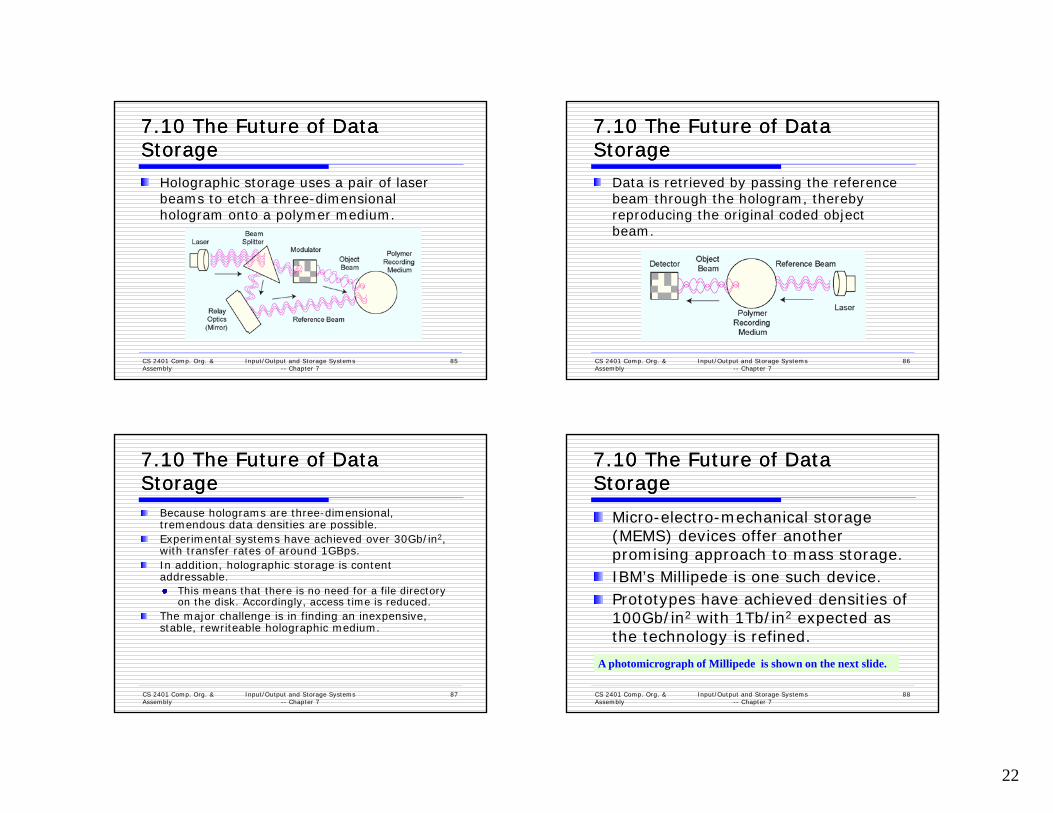
Holographic storage uses a pair of laser b h h di i l beams to etch a three-dimensional hologram onto a polymer medium.
CS 2401 Comp. Org. & Assembly
Input/Output and Storage Systems -- Chapter 7
85
7.10 The Future of Data 7.10 The Future of Data StorageStorage
Data is retrieved by passing the reference b h h h h l h b beam through the hologram, thereby reproducing the original coded object beam.
CS 2401 Comp. Org. & Assembly
Input/Output and Storage Systems -- Chapter 7
86
7.10 The Future of Data 7.10 The Future of Data StorageStorage
Because holograms are three-dimensional, tremendous data densities are possible.tremendous data densities are possible.Experimental systems have achieved over 30Gb/in2, with transfer rates of around 1GBps.In addition, holographic storage is content addressable.
This means that there is no need for a file directory on the disk. Accordingly, access time is reduced.
The major challenge is in finding an inexpensive,
CS 2401 Comp. Org. & Assembly
Input/Output and Storage Systems -- Chapter 7
87
j g g p ,stable, rewriteable holographic medium.
7.10 The Future of Data 7.10 The Future of Data StorageStorage
Micro-electro-mechanical storage (MEMS) devices offer another promising approach to mass storage.IBM’s Millipede is one such device.Prototypes have achieved densities of 100Gb/in2 with 1Tb/in2 expected as
CS 2401 Comp. Org. & Assembly
Input/Output and Storage Systems -- Chapter 7
88
100Gb/in with 1Tb/in expected as the technology is refined.
A photomicrograph of Millipede is shown on the next slide.A photomicrograph of Millipede is shown on the next slide.

23
7.10 The Future of Data 7.10 The Future of Data StorageStorage
Millipede consists f th d f of thousands of
cantilevers that record a binary 1 by pressing a heated tip into a polymer
b t t
CS 2401 Comp. Org. & Assembly
Input/Output and Storage Systems -- Chapter 7
89
substrate.The tip reads a binary 1 when it dips into the imprint in the polymer
Photomicrograph courtesy of the IBM Corporation.© 2005 IBM Corporation
Photomicrograph courtesy of the IBM Corporation.© 2005 IBM Corporation
CS 2401 Comp. Org. & Assembly
Input/Output and Storage Systems -- Chapter 7
90
Chapter 7 ConclusionChapter 7 ConclusionI/O systems are critical to the overall performance of a computer systemperformance of a computer system.Amdahl’s Law quantifies this assertion.I/O systems consist of memory blocks, cabling, control circuitry, interfaces, and media.I/O control methods include programmed I/O, interrupt-based I/O, DMA, and channel /O
CS 2401 Comp. Org. & Assembly
Input/Output and Storage Systems -- Chapter 7
91
I/O.Buses require control lines, a clock, and data lines. Timing diagrams specify operational details.
Chapter 7 ConclusionChapter 7 ConclusionMagnetic disk is the principal form of durable storagestorage.Disk performance metrics include seek time, rotational delay, and reliability estimates.Optical disks provide long-term storage for large amounts of data, although access is slow.Magnetic tape is also an archival medium
CS 2401 Comp. Org. & Assembly
Input/Output and Storage Systems -- Chapter 7
92
Magnetic tape is also an archival medium. Recording methods are track-based, serpentine, and helical scan.

24
Chapter 7 ConclusionChapter 7 ConclusionRAID gives disk systems improved performance and reliability RAID 3 and RAID performance and reliability. RAID 3 and RAID 5 are the most common.RAID 6 and RAID DP protect against dual disk failure, but RAID DP offers better performance. Any one of several new technologies including biological, holographic, or mechanical may someday replace magnetic
CS 2401 Comp. Org. & Assembly
Input/Output and Storage Systems -- Chapter 7
93
mechanical may someday replace magnetic disks.The hardest part of data storage may be end up be in locating the data after it’s stored.