Input/Output · ¡CPU issues instruction to IOP ¡Device to/from memory transfers are controlled by...
54
1 Input/Output
Transcript of Input/Output · ¡CPU issues instruction to IOP ¡Device to/from memory transfers are controlled by...
1
Input/Output
2
Introduction
MotivationPerformance metricsProcessor interface issuesBuses
3
Motivation
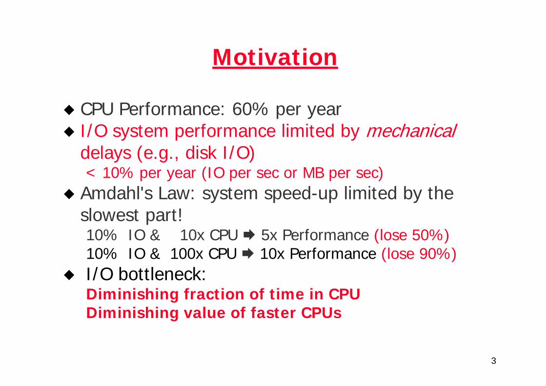
CPU Performance: 60% per yearI/O system performance limited by mechanicaldelays (e.g., disk I/O)< 10% per year (IO per sec or MB per sec)
Amdahl's Law: system speed-up limited by the slowest part!10% IO & 10x CPU 5x Performance (lose 50%)10% IO & 100x CPU 10x Performance (lose 90%)I/O bottleneck: Diminishing fraction of time in CPUDiminishing value of faster CPUs
4
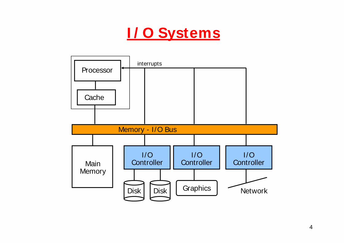
I/O Systems
Processor
Cache
Memory - I/O Bus
MainMemory
I/OController
Disk Disk
I/OController
I/OController
Graphics Network
interrupts
5
I/O performance metrics
6
I/O performance
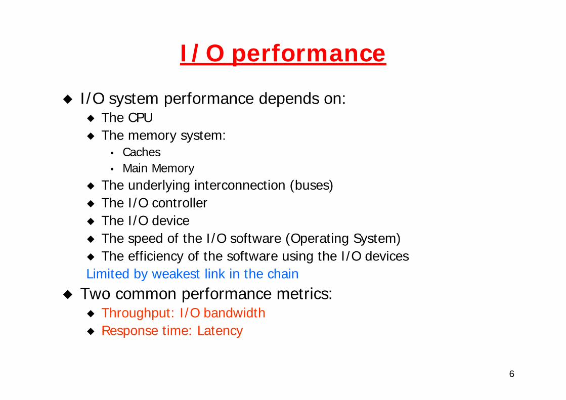
I/O system performance depends on:The CPUThe memory system:
• Caches• Main Memory
The underlying interconnection (buses)The I/O controllerThe I/O deviceThe speed of the I/O software (Operating System)The efficiency of the software using the I/O devices
Limited by weakest link in the chainTwo common performance metrics:
Throughput: I/O bandwidthResponse time: Latency
7
Throughput vs. response time
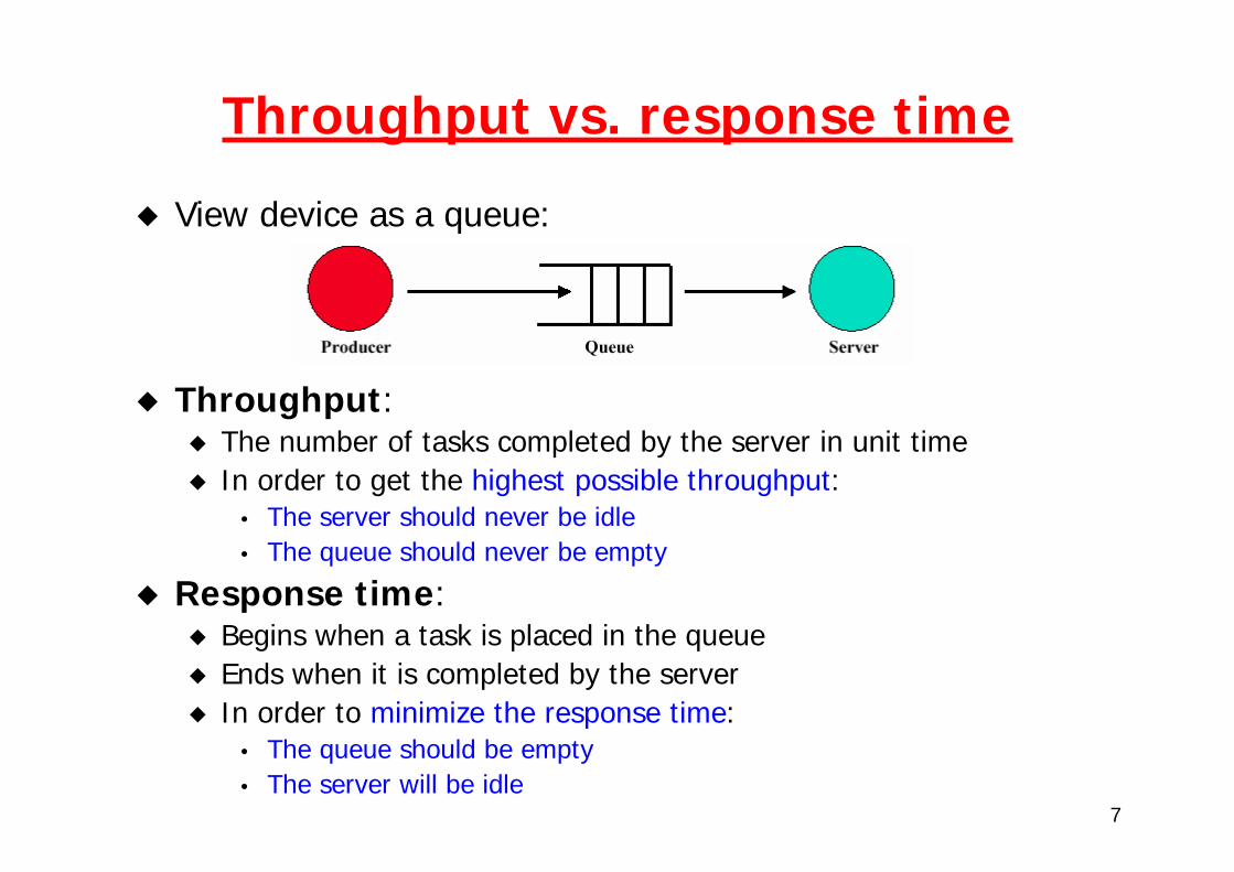
View device as a queue:
Throughput:The number of tasks completed by the server in unit timeIn order to get the highest possible throughput:
• The server should never be idle• The queue should never be empty
Response time:Begins when a task is placed in the queueEnds when it is completed by the serverIn order to minimize the response time:
• The queue should be empty• The server will be idle
8
Throughput vs. response time (2)
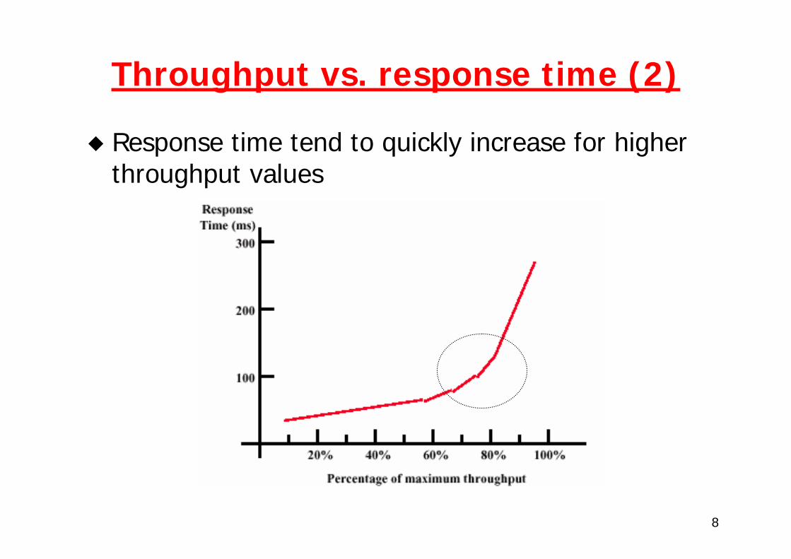
Response time tend to quickly increase for higher throughput values
9
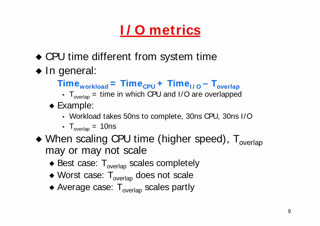
I/O metrics
CPU time different from system timeIn general:
Timeworkload = TimeCPU + TimeI/O – Toverlap• Toverlap = time in which CPU and I/O are overlapped
Example:• Workload takes 50ns to complete, 30ns CPU, 30ns I/O• Toverlap = 10ns
When scaling CPU time (higher speed), Toverlapmay or may not scale
Best case: Toverlap scales completelyWorst case: Toverlap does not scaleAverage case: Toverlap scales partly
10
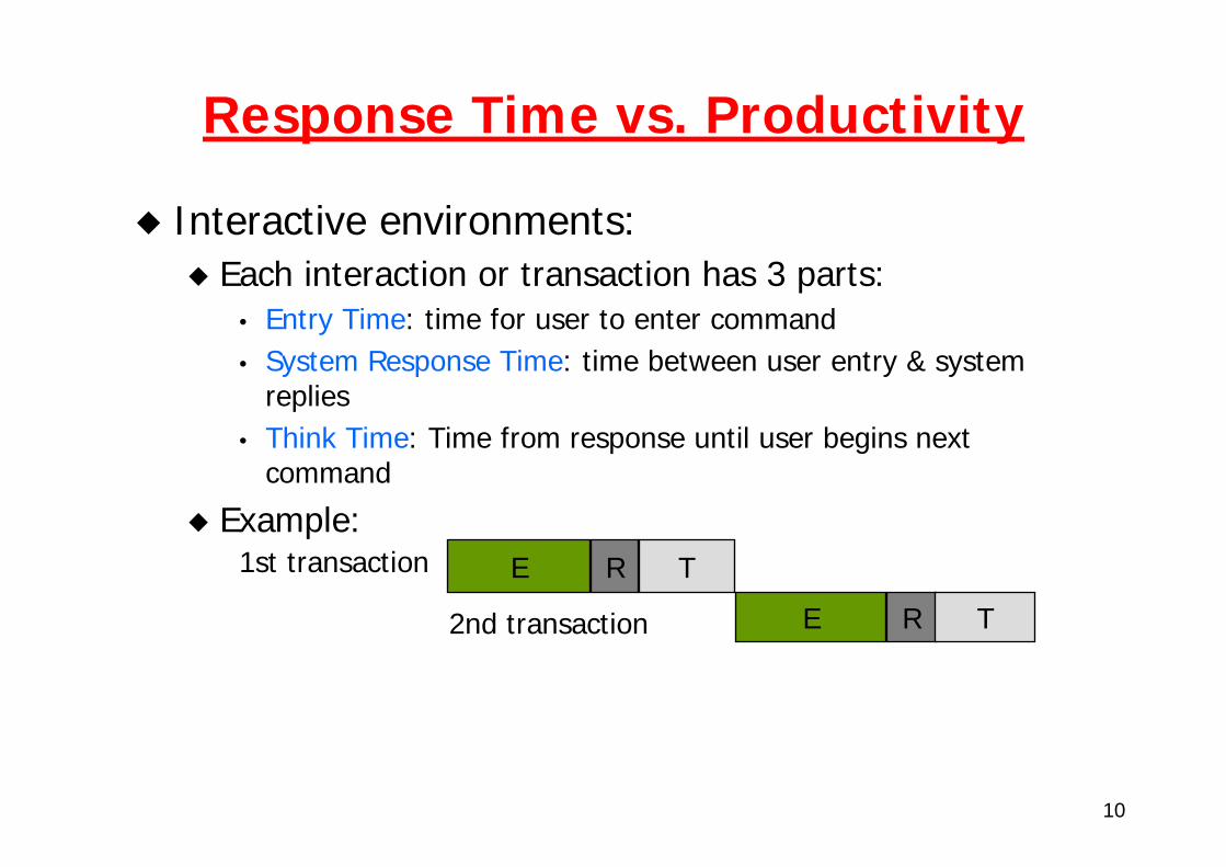
Response Time vs. Productivity
Interactive environments: Each interaction or transaction has 3 parts:
• Entry Time: time for user to enter command• System Response Time: time between user entry & system
replies• Think Time: Time from response until user begins next
command
Example:1st transaction
2nd transaction
E R T
E R T
11
Time
0.00 5.00 10.00 15.00
graphics1.0s
graphics0.3s
conventional1.0s
conventional0.3s
entry resp think
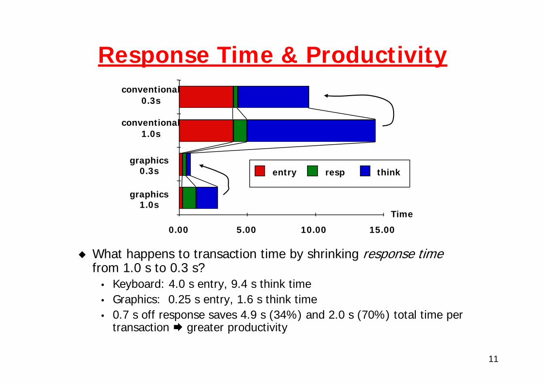
Response Time & Productivity
What happens to transaction time by shrinking response timefrom 1.0 s to 0.3 s?
• Keyboard: 4.0 s entry, 9.4 s think time• Graphics: 0.25 s entry, 1.6 s think time• 0.7 s off response saves 4.9 s (34%) and 2.0 s (70%) total time per
transaction greater productivity
12
Processor interface issues
13
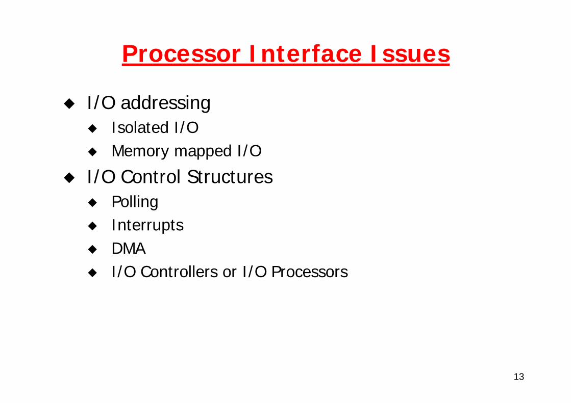
Processor Interface Issues
I/O addressingIsolated I/OMemory mapped I/O
I/O Control StructuresPollingInterruptsDMAI/O Controllers or I/O Processors
14
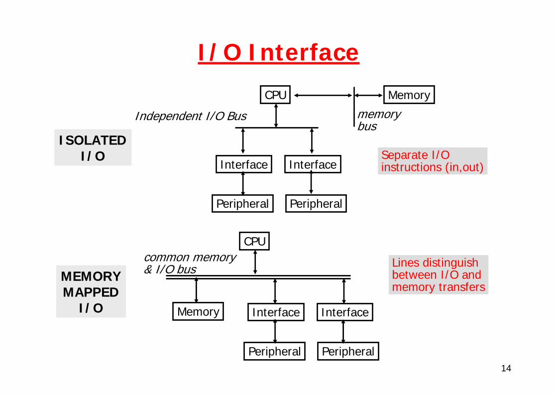
I/O Interface
Independent I/O Bus
CPU
Interface Interface
Peripheral Peripheral
Memory
memorybus
Separate I/O instructions (in,out)
Lines distinguish between I/O and memory transfers
CPU
Interface Interface
Peripheral Peripheral
Memory
common memory& I/O bus
ISOLATEDI/O
MEMORYMAPPED
I/O
15
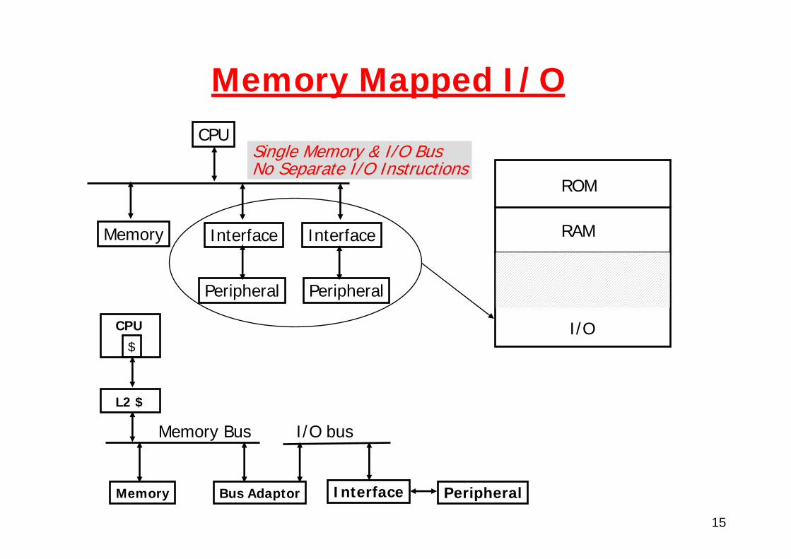
Memory Mapped I/O
Single Memory & I/O Bus No Separate I/O Instructions
CPU
Interface Interface
Peripheral Peripheral
Memory
ROM
RAM
I/O$
CPU
L2 $
Memory Bus
Memory Bus Adaptor
I/O bus
Interface Peripheral
16
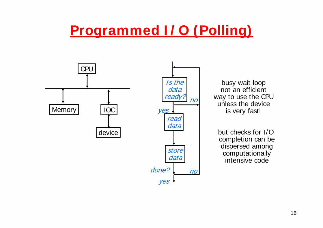
Programmed I/O (Polling)
CPU
IOC
device
Memory
Is thedata
ready?
readdata
storedata
yesno
done? noyes
busy wait loopnot an efficient
way to use the CPUunless the device
is very fast!
but checks for I/O completion can bedispersed amongcomputationallyintensive code

17
Interrupt Driven Data Transfer
User program progress only halted during actual transferExample: 1000 transfers at 1 ms each:
1000 interrupts @ 2 µs per interrupt1000 interrupt service @ 98 µs each = 0.1 CPU secondsDevice transfer rate = 10 MB/s => 0.1 x 10⁻⁶ s/B => 0.1 µs/B
1000 bytes = 100 µsec 1000 transfers x 100 µsecs = 100 ms = 0.1 CPU seconds
CPU
IOC
device
Memory
interruptserviceroutine
addsubandornop
readstore...rti
memory
userprogram
(1) I/Ointerrupt
(2) save PC
(3) interruptservice addr
(4)
50% overhead
18
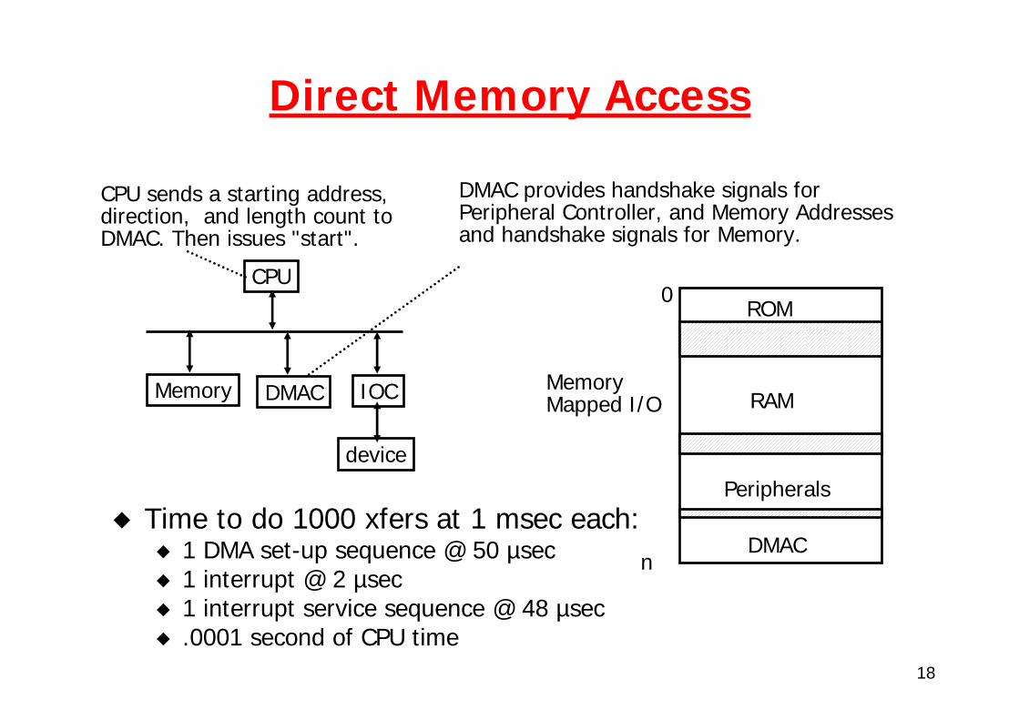
Direct Memory Access
Time to do 1000 xfers at 1 msec each:1 DMA set-up sequence @ 50 µsec1 interrupt @ 2 µsec1 interrupt service sequence @ 48 µsec.0001 second of CPU time
CPU
IOC
device
Memory DMAC
CPU sends a starting address, direction, and length count to DMAC. Then issues "start".
DMAC provides handshake signals for Peripheral Controller, and Memory Addresses and handshake signals for Memory.
0ROM
RAM
Peripherals
DMACn
Memory Mapped I/O
19
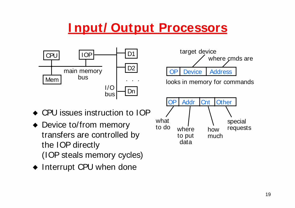
Input/Output Processors
CPU issues instruction to IOPDevice to/from memory transfers are controlled by the IOP directly (IOP steals memory cycles)Interrupt CPU when done
CPU IOP
Mem
D1
D2
Dn
. . .main memory
bus
I/Obus
OP Device Address
target devicewhere cmds are
looks in memory for commands
OP Addr Cnt Other
whatto do where
to putdata
howmuch
specialrequests
20
Relationship to Processor Architecture
I/O instructions have largely disappearedInterrupts:
Stack replaced by shadow registers• Handler saves registers and re-enables higher
priority interrupts• Interrupt types reduced in number;
handler must query interrupt controller
Caches cause problems for I/OFlushing is expensive, I/O pollutes cacheSolution is borrowed from shared memory multiprocessors "snooping"
21
Bus & interconnects
22
Bus & interconnects
Bus classificationBus transactionsBus timing
23
What is a bus?
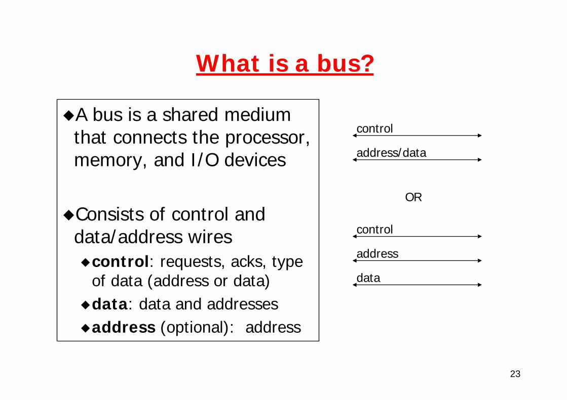
A bus is a shared medium that connects the processor, memory, and I/O devices
Consists of control and data/address wires
control: requests, acks, type of data (address or data)data: data and addressesaddress (optional): address
control
address/data
control
address
data
OR
24
Bus-Based Interconnect
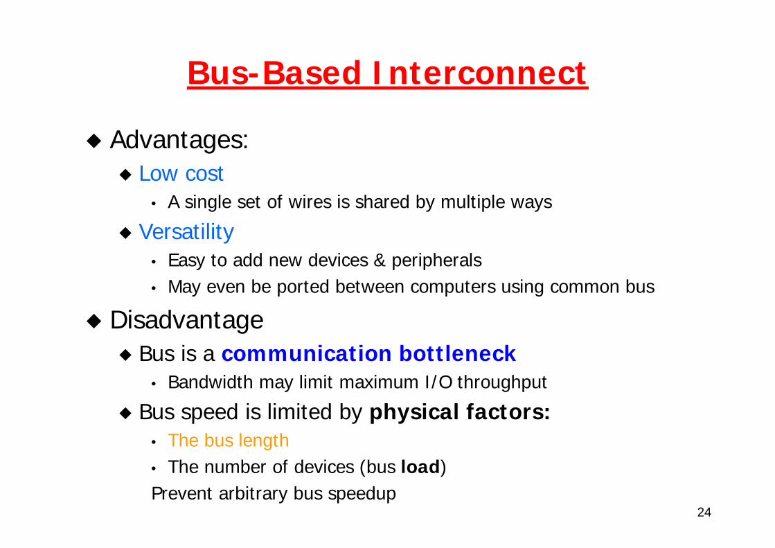
Advantages:Low cost
• A single set of wires is shared by multiple ways
Versatility• Easy to add new devices & peripherals • May even be ported between computers using common bus
DisadvantageBus is a communication bottleneck
• Bandwidth may limit maximum I/O throughput
Bus speed is limited by physical factors:• The bus length• The number of devices (bus load) Prevent arbitrary bus speedup
25
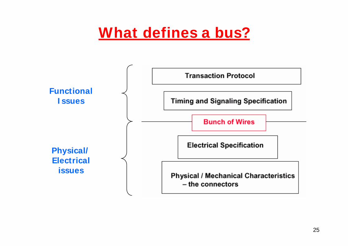
What defines a bus?
FunctionalIssues
Physical/Electrical
issues
26
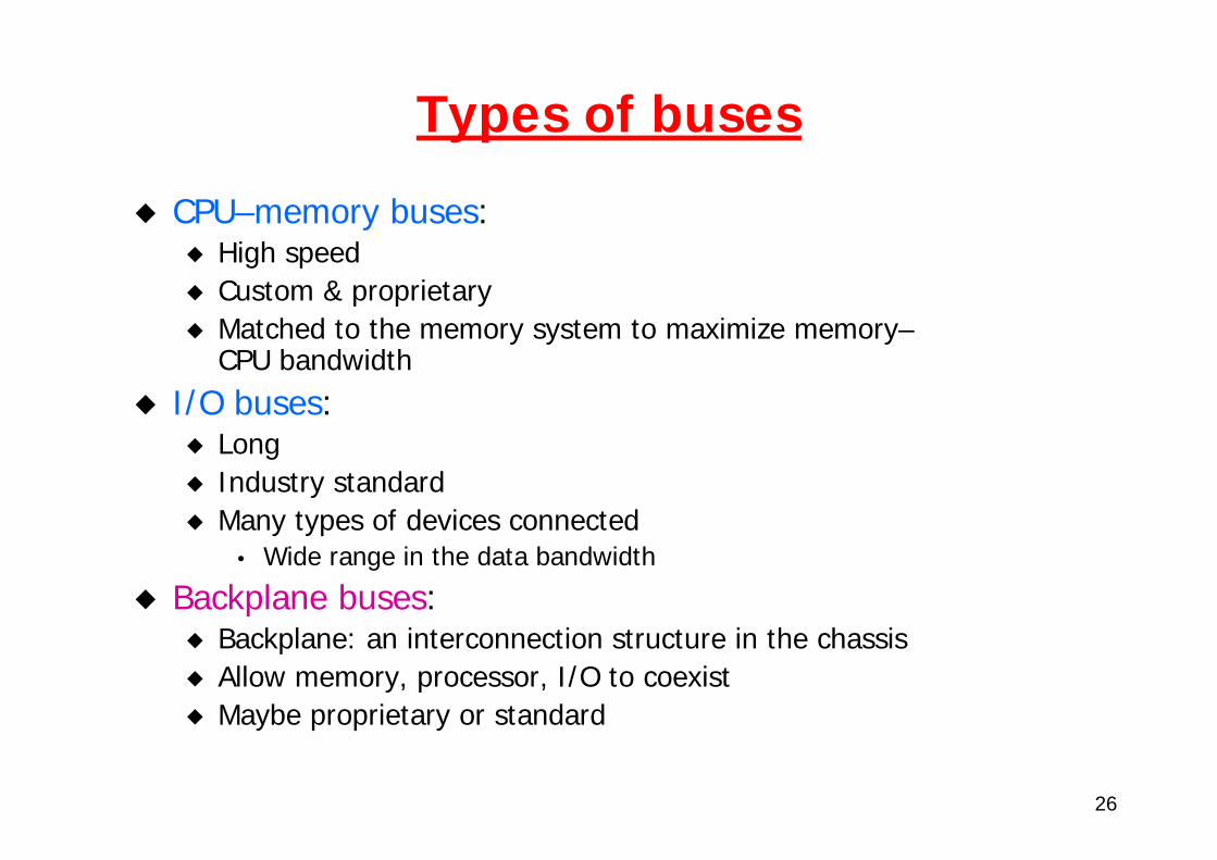
Types of buses
CPU–memory buses:High speedCustom & proprietaryMatched to the memory system to maximize memory–CPU bandwidth
I/O buses: LongIndustry standardMany types of devices connected
• Wide range in the data bandwidth
Backplane buses:Backplane: an interconnection structure in the chassisAllow memory, processor, I/O to coexistMaybe proprietary or standard
27
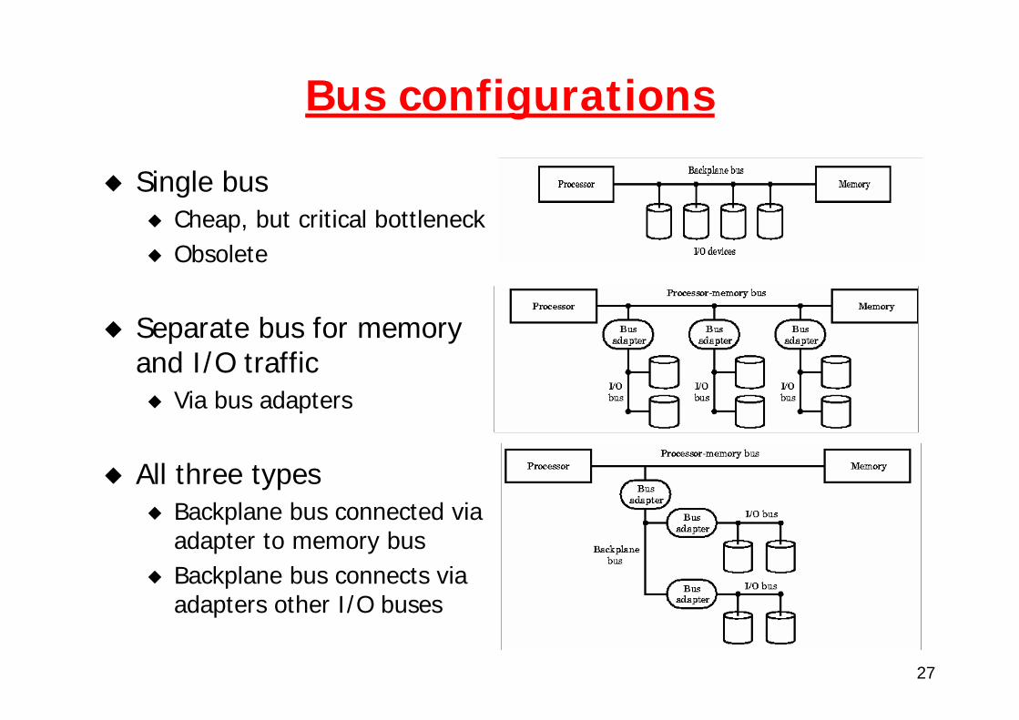
Bus configurations
Single busCheap, but critical bottleneckObsolete
Separate bus for memory and I/O traffic
Via bus adapters
All three typesBackplane bus connected via adapter to memory busBackplane bus connects via adapters other I/O buses
28
Bus clocking
Synchronous Bus:Includes a clock in the control lines
• Defines bus cycle (= N clock cycles)A fixed protocol for communication that is relative to the clockAdvantage:
• Involves very little logic and can run very fastDisadvantages:
• Every device on the bus must run at the same clock rate• Older devices may not work
• To avoid clock skew, they cannot be long if they are fast
Asynchronous Bus:Not clockedCan accommodate a wide range of devicesCan be lengthened without worrying about clock skewRequires a handshaking protocol
29
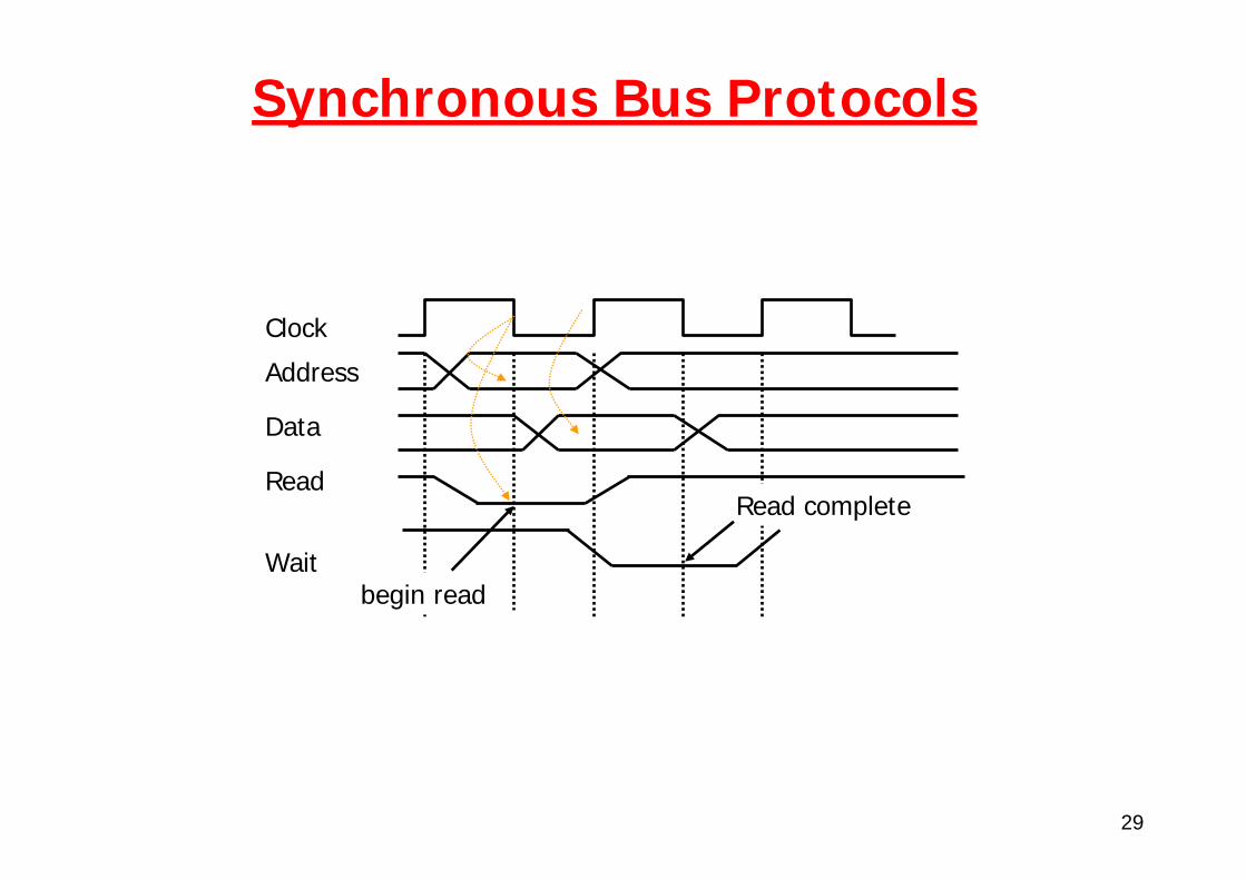
Synchronous Bus Protocols
Address
Data
Read
Wait
Clock
begin read
Read complete
30
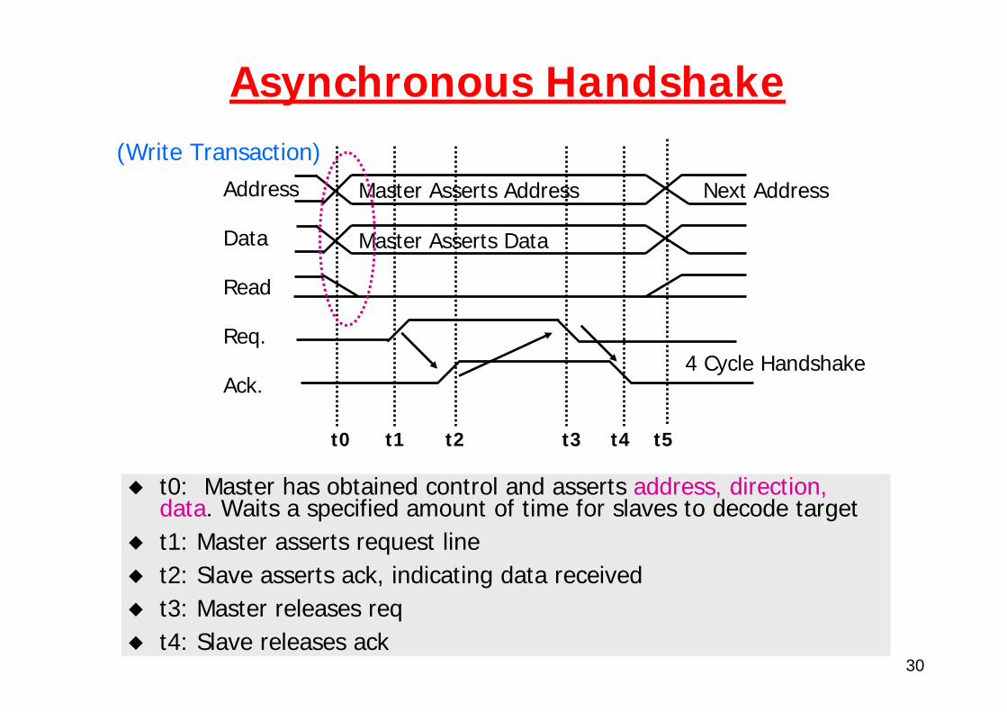
Asynchronous Handshake
Address
Data
Read
Req.
Ack.
Master Asserts Address
Master Asserts Data
Next Address
(Write Transaction)
t0 t1 t2 t3 t4 t5
t0: Master has obtained control and asserts address, direction, data. Waits a specified amount of time for slaves to decode targett1: Master asserts request linet2: Slave asserts ack, indicating data receivedt3: Master releases reqt4: Slave releases ack
4 Cycle Handshake
31
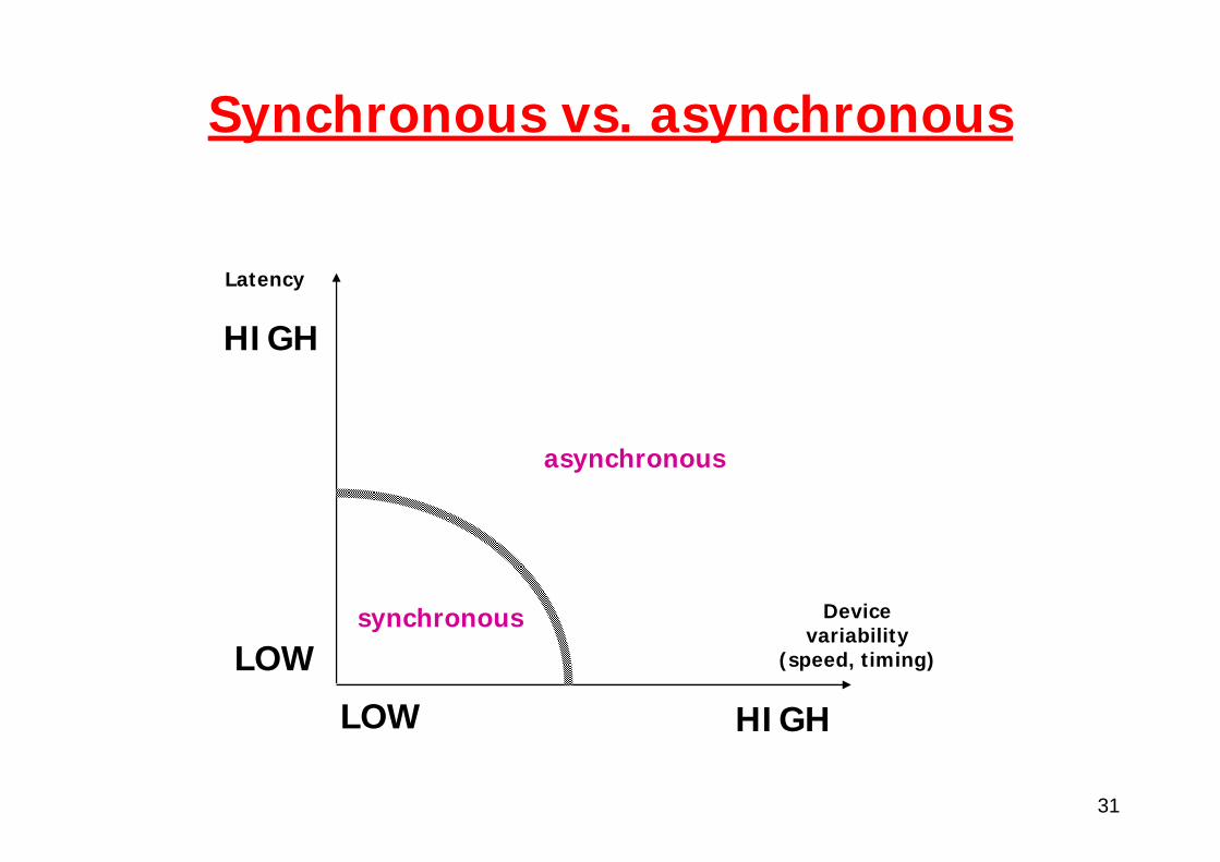
Synchronous vs. asynchronous
Devicevariability
(speed, timing)
LOW HIGH
Latency
LOW
HIGH
synchronous
asynchronous
32
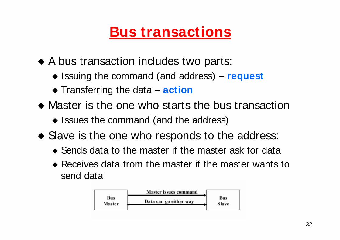
Bus transactions
A bus transaction includes two parts:Issuing the command (and address) – requestTransferring the data – action
Master is the one who starts the bus transaction Issues the command (and the address)
Slave is the one who responds to the address:Sends data to the master if the master ask for dataReceives data from the master if the master wants to send data
33
Arbitration
Problem:How is the bus reserved by a devices that wishes to use it?
Chaos is avoided by a master-slave arrangement:Only the bus master can control access to the bus:A slave responds to read and write requests
The simplest system:Processor is the only bus masterAll bus requests must be controlled by the processorDrawback: the processor is involved in every transaction
34
Arbitration (2)
Consequence: need multiple bus mastersManaging multiple masters requires arbitration!
Arbitration goals:Functionality
• Prevent bus conflicts (two bussed simultaneous drivers)Performance
• Need to make decisions quicklyPriority
• Some masters maybe more desperate than others• Example: DRAM refresh
Fairness• Every equal priority master should get equal service• No starvation: Every requestor should eventually get bus
35
Arbitration (3)
Arbitration schemes:Daisy chain arbitration:
• single device with all request lines.
CentralizedDistributed arbitration by self-selection
• each device wanting the bus places a code indicating its identity on the bus
• Requires some sort of state duplication
Distributed arbitration by collision detection • e.g., as for Ethernet

36
Daisy-chained arbitration
Advantage: simpleDisadvantages: Cannot assure fairness
A low-priority device may be locked out indefinitelyThe use of the daisy chain grant signal also limits the bus speed
37
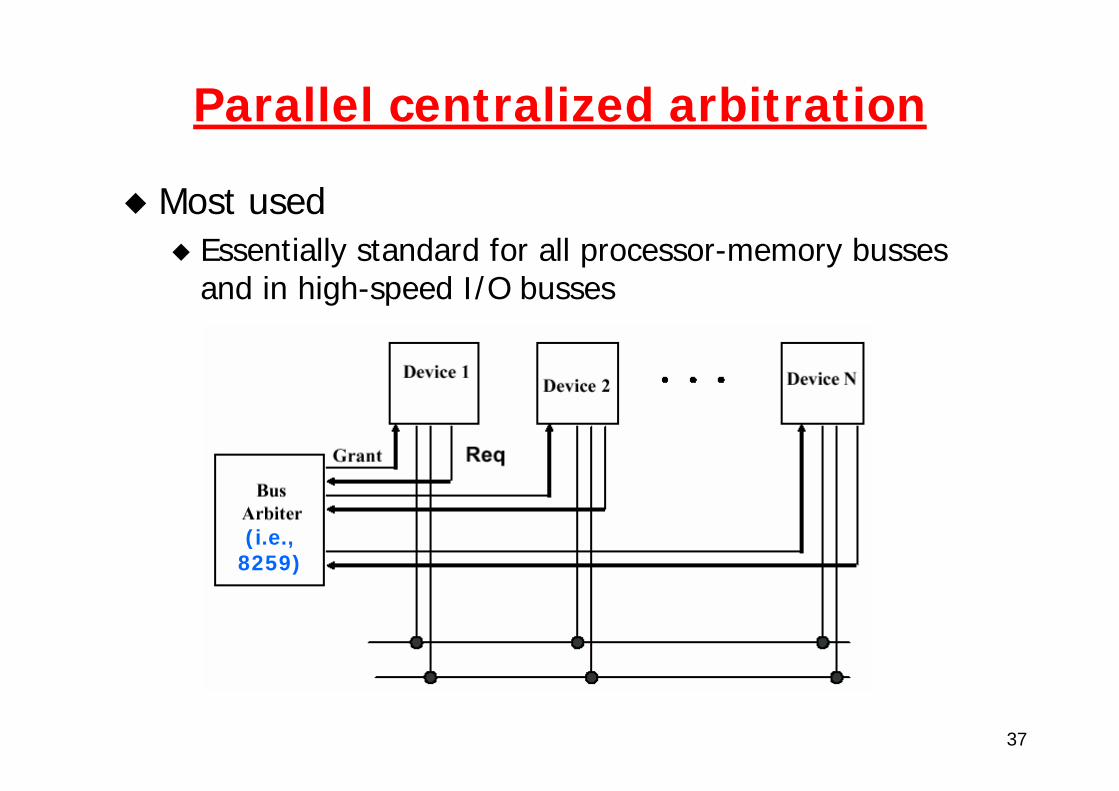
Parallel centralized arbitration
Most used Essentially standard for all processor-memory busses and in high-speed I/O busses
(i.e.,8259)
38
Bus performance optimization
Improving bandwidth:Separate vs. multiplexed address and bus lines
• Address and data can be transmitted in one bus cycle if separate
Data bus width:• Transfers of multiple words require fewer bus cycles
Block transfers:• Allow the bus to transfer multiple words in back-to-back
bus cycles• Only one address needs to be sent at the beginning
39
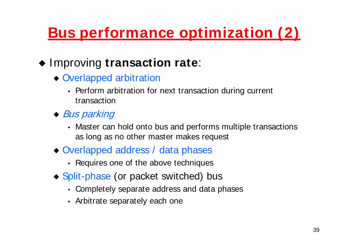
Bus performance optimization (2)
Improving transaction rate:Overlapped arbitration
• Perform arbitration for next transaction during current transaction
Bus parking• Master can hold onto bus and performs multiple transactions
as long as no other master makes request
Overlapped address / data phases• Requires one of the above techniques
Split-phase (or packet switched) bus• Completely separate address and data phases• Arbitrate separately each one
40
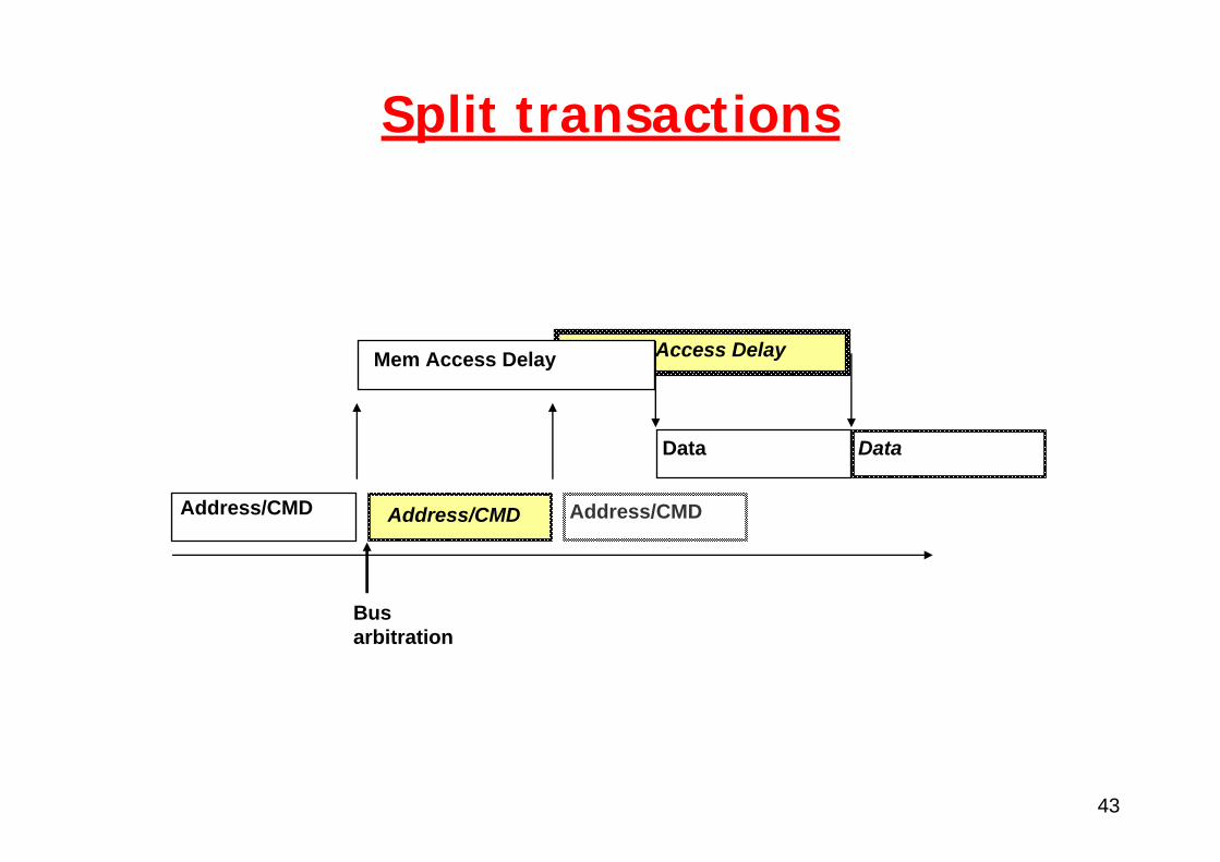
Split transaction bus (1)
With multiple masters, a bus can offer higher bandwidth by going to packets, as opposed to holding the bus for a full transaction.This technique is called split transactions.The read transaction is now split into
A read request transaction that contains the addressA memory reply transaction that contains the data.
41
Split transaction bus (2)
On a split transaction bus, each transaction must be tagged so that the processor and memory can tell what it is. Split transactions make the bus available for othermasters while the memory reads the words from the requested address.The CPU must arbitrate for the bus in order to send the data and the memory must arbitrate in order to return the data.
Higher bandwidthHigher latency
than non-split buses
42
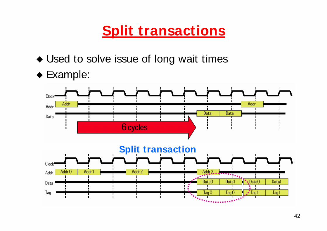
Split transactions
Used to solve issue of long wait timesExample:
Split transaction
43
Split transactions
Mem Access Delay
Address/CMD
Mem Access Delay
Data
Address/CMD
Data
Address/CMD
Busarbitration
44
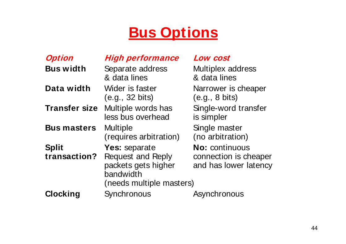
Bus OptionsOption High performance Low costBus width Separate address Multiplex address
& data lines & data linesData width Wider is faster Narrower is cheaper
(e.g., 32 bits) (e.g., 8 bits)Transfer size Multiple words has Single-word transfer
less bus overhead is simplerBus masters Multiple Single master
(requires arbitration) (no arbitration)Split Yes: separate No: continuous transaction? Request and Reply connection is cheaper
packets gets higher and has lower latencybandwidth(needs multiple masters)
Clocking Synchronous Asynchronous

45
1993 MP Memory Bus Survey
Bus Summit Challenge XDBusOriginator HP SGI SunClock Rate (MHz) 60 48 66
Split transaction? Yes Yes Yes? Address lines 48 40 ??Data lines 128 256 144 (parity)Data Sizes (bits) 512 1024 512Clocks/transfer 4 5 4?Peak (MB/s) 960 1200 1056Master Multi Multi MultiArbitration Central Central CentralAddressing Physical Physical PhysicalSlots 16 9 10Busses/system 1 1 2Length 13 inches 12? inches 17 inches

46
I/O buses
Designed to support wide variety of devicesFull set not know at design timeAllow data rate match between arbitrary speed devices
Typically asynchronousModern I/O buses (especially for fast I/O) synchronous as well
47
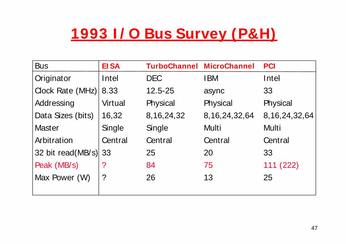
1993 I/O Bus Survey (P&H)
Bus EISA TurboChannel MicroChannel PCI
Originator Intel DEC IBM IntelClock Rate (MHz) 8.33 12.5-25 async 33Addressing Virtual Physical Physical PhysicalData Sizes (bits) 16,32 8,16,24,32 8,16,24,32,64 8,16,24,32,64Master Single Single Multi MultiArbitration Central Central Central Central32 bit read(MB/s) 33 25 20 33Peak (MB/s) ? 84 75 111 (222)Max Power (W) ? 26 13 25
48
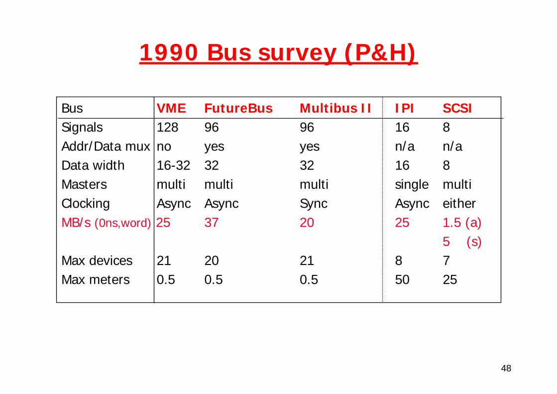
1990 Bus survey (P&H)
Bus VME FutureBus Multibus II IPI SCSISignals 128 96 96 16 8Addr/Data mux no yes yes n/a n/aData width 16-32 32 32 16 8Masters multi multi multi single multiClocking Async Async Sync Async eitherMB/s (0ns,word) 25 37 20 25 1.5 (a)
5 (s)Max devices 21 20 21 8 7Max meters 0.5 0.5 0.5 50 25

49
Modern bus architectures
Modern architectures employ a hierarchical bus structure
Host bus • Processor/memory bus• No standard
Local bus• Fast peripherals• PCI is the standard
Expansion bus• Slow peripherals, i.e., true I/O bus• Corresponds to older “system bus”• ISA is the standard
No clear notion of “backplane” bus
50
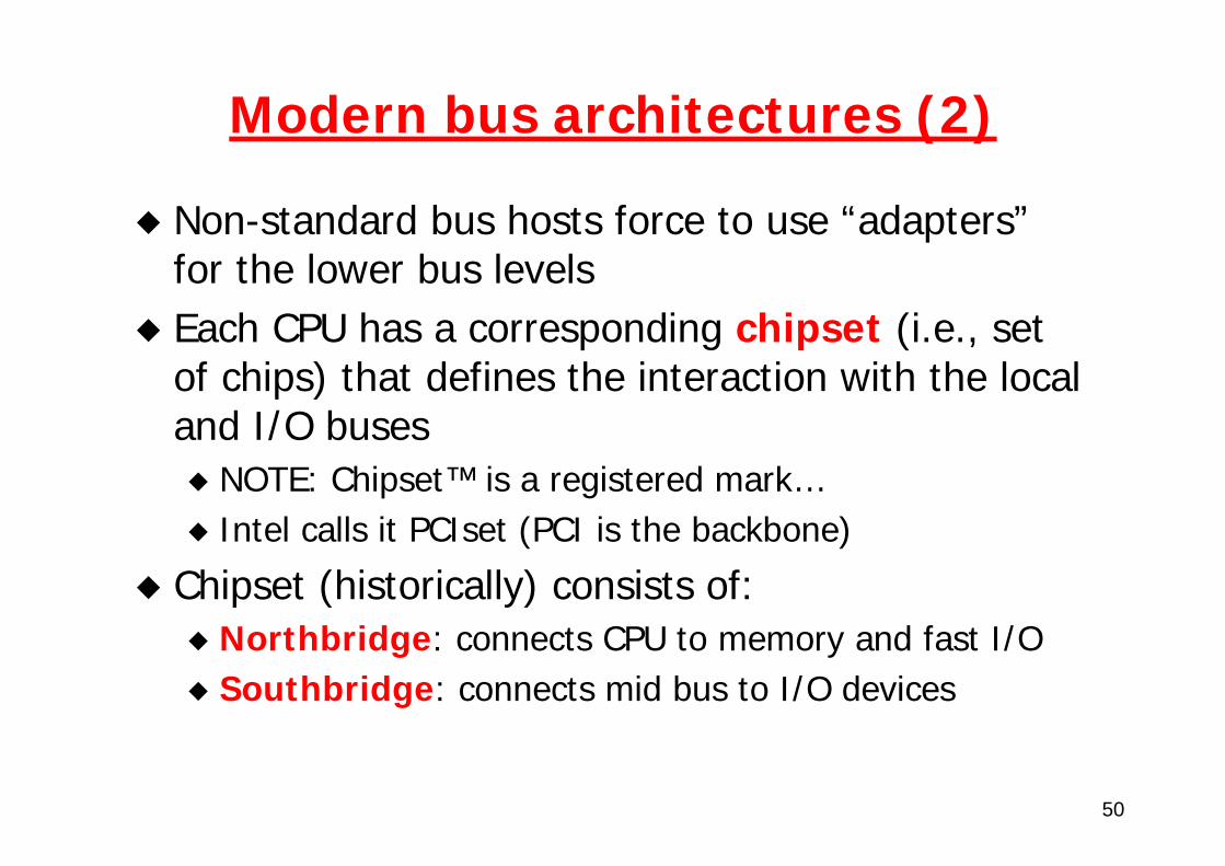
Modern bus architectures (2)
Non-standard bus hosts force to use “adapters”for the lower bus levelsEach CPU has a corresponding chipset (i.e., set of chips) that defines the interaction with the local and I/O buses
NOTE: Chipset™ is a registered mark…Intel calls it PCIset (PCI is the backbone)
Chipset (historically) consists of:Northbridge: connects CPU to memory and fast I/OSouthbridge: connects mid bus to I/O devices
51
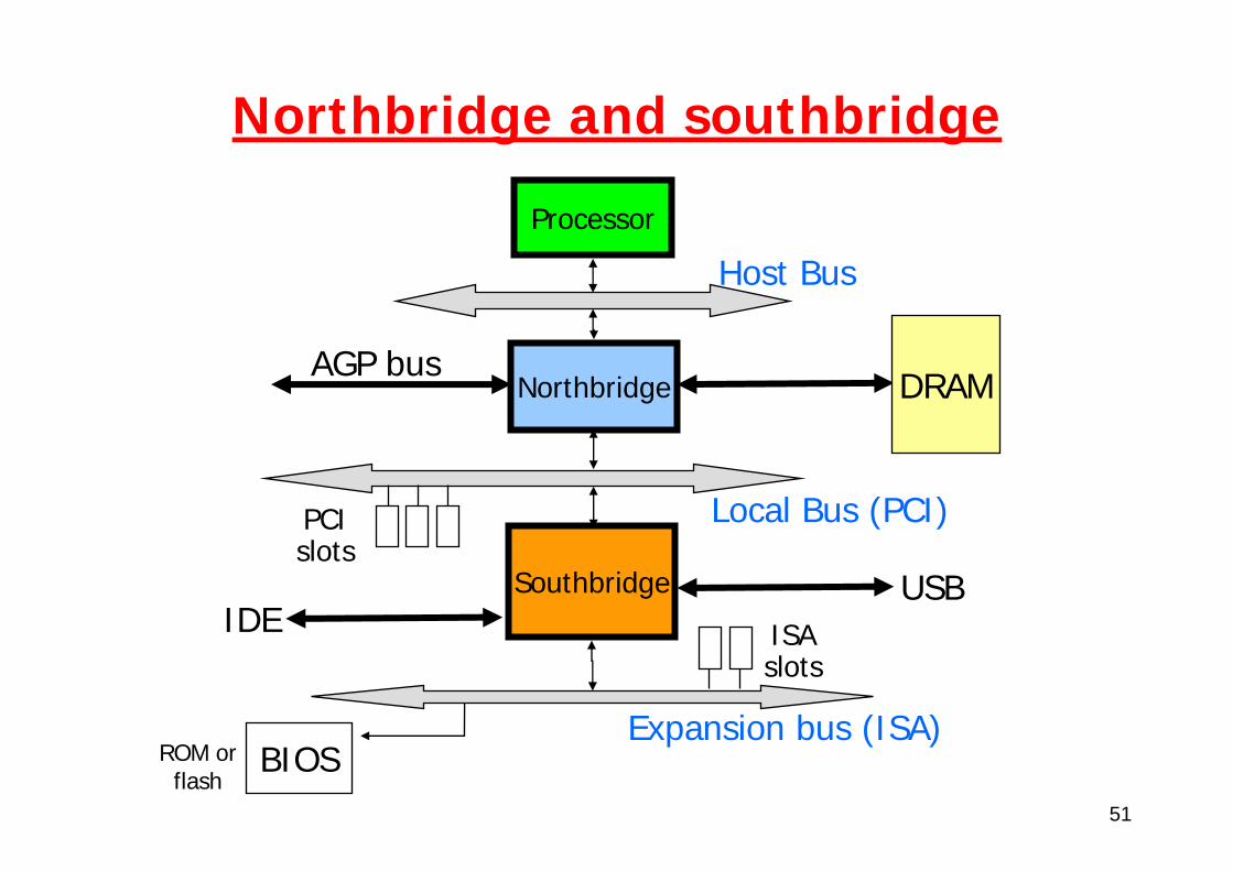
Northbridge and southbridge
Processor
Northbridge
Southbridge
Host Bus
Local Bus (PCI)
Expansion bus (ISA)
AGP bus
PCIslots
BIOS
ISAslots
DRAM
USBIDE
ROM orflash
52
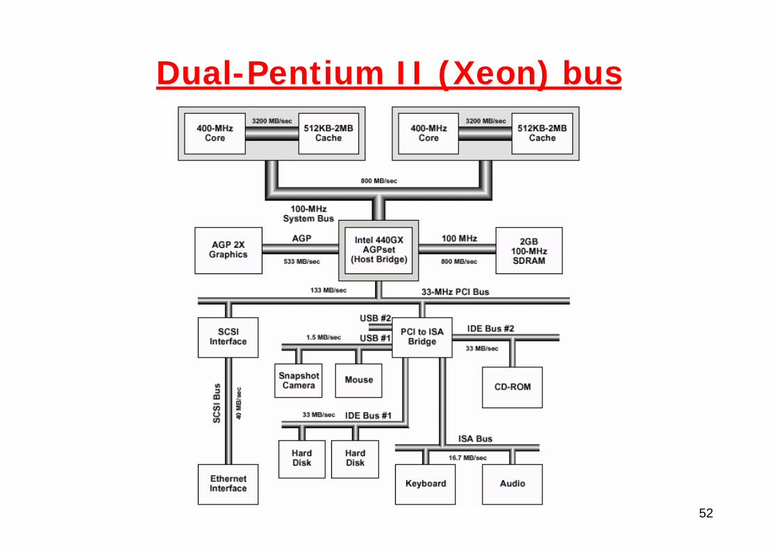
Dual-Pentium II (Xeon) bus
53
Pentium chipsets
With PentiumIII, Intel has moved towards a slightly different architecture
Memory controller hub (MCH, replaces NB)I/O controller hub (ICH, replaces SB)Firmware controller hub (FCH)
Conceptually similar, but:PCI is not central anymoreConnection MCH-ICH through a dedicated, 8-bit bus @266MHz (2x PCI)
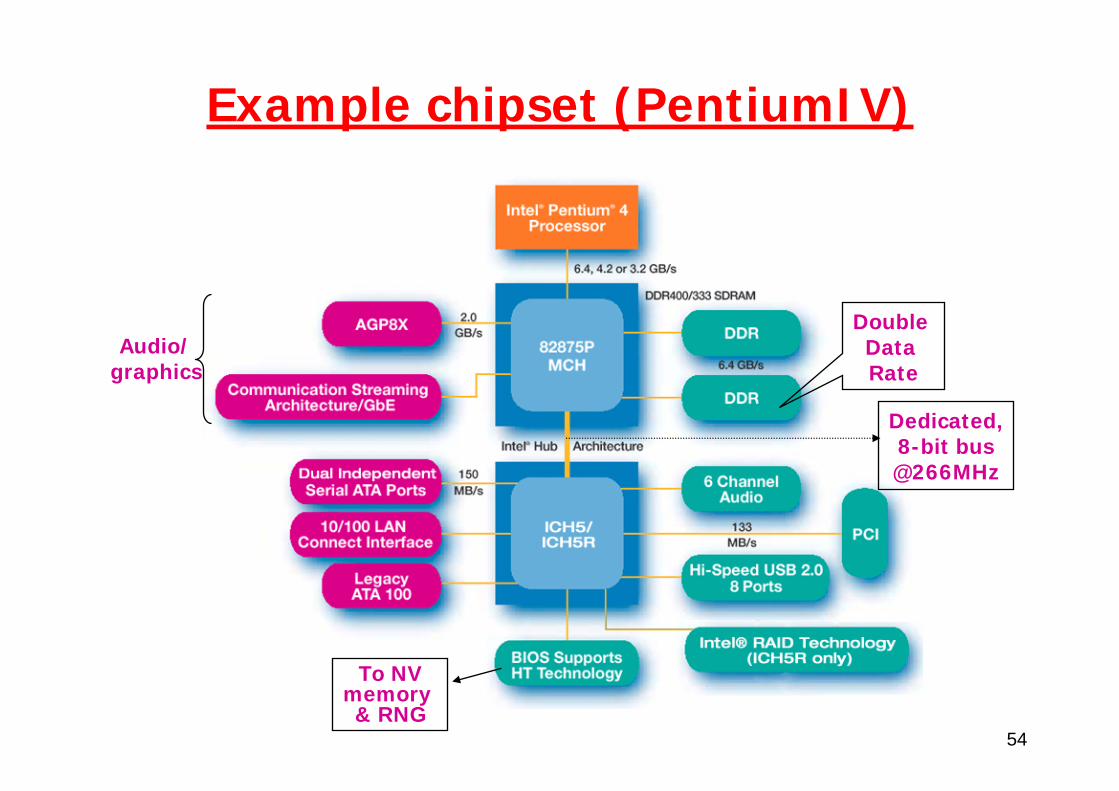
54
Example chipset (PentiumIV)
Double Data Rate
Audio/graphics
To NVmemory & RNG
Dedicated,8-bit bus@266MHz