INPRO FUEL HANDLING EQUIPMENTS FOR DIESEL GENERATORS · INPRO FUEL HANDLING EQUIPMENTS FOR DIESEL...
40
INPRO FUEL HANDLING EQUIPMENTS FOR DIESEL GENERATORS PUMP SET DIGITAL CONTROLS CONTROL VALVES FILTERS AND FUEL POLISHERS OIL METERS FUEL POLISHERS
Transcript of INPRO FUEL HANDLING EQUIPMENTS FOR DIESEL GENERATORS · INPRO FUEL HANDLING EQUIPMENTS FOR DIESEL...
INPRO FUEL HANDLING EQUIPMENTS FOR DIESEL GENERATORS
PUMP SET
DIGITAL CONTROLS
CONTROL VALVES
FILTERS AND FUEL POLISHERS
OIL METERS
FUEL POLISHERS
INPRO – Bringing value to your projects
Why Inpro?
Inpro has 50 years’ experience in automation systems for heat production, power generation plants and
datacentres, marine vessel, airport liquid fuel management, railway automation components, food industry,
oil industry, residential and commercial projects as hospitals, hotel buildings, or production facilities, bringing
liquid fuel management and at the highest technical standard installations worldwide.
We want to bring to your outstanding projects the value of the consulting and engineering challenges that we
have faced with the knowledge of our professionals, the experience gained over the years and implementing
the most advanced technology:Don’t miss the chance to speak with our engineers to keep on the efficient,
safe and reliable building or installation technique for your energy system.
Why compact equipment?
All our solutions leave our factory designed and tested, to allow a quick installation at your location, to
warranty a safe and reliable function at any critical facility. Quality, reliability and security are the reasons why
our customers have chosen us: Trouble-free commissioning & maintenance for your installation.
Who has already selected Inpro?
Some of our customers are:
Comunidad de Madrid
3
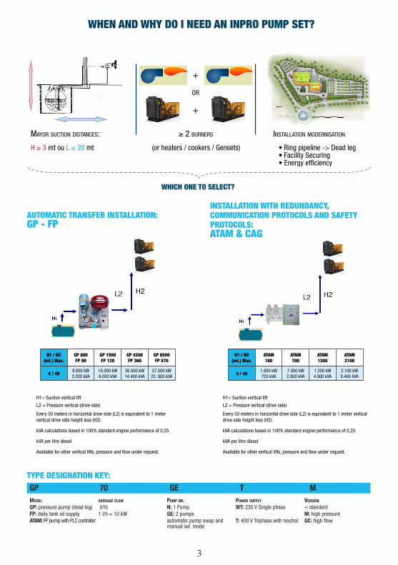
WHEN AND WHY DO I NEED AN INPRO PUMP SET?
Mayor suction distances: ≥ 2 burners installation Modernisation
H ≥ 3 mt ou L ≥ 20 mt (or heaters / cookers / Gensets) • Ring pipeline -> Dead leg• Facility Securing• Energy efficiency
WHICH ONE TO SELECT?
AUTOMATIC TRANSFER INSTALLATION: GP - FP
INSTALLATION WITH REDUNDANCY,COMMUNICATION PROTOCOLS AND SAFETYPROTOCOLS: ATAM & CAG
TYPE DESIGNATION KEY:GP 70 GE T MModEl avEraGE flow PuMP nr. PowEr suPPly vErsion
GP: pressure pump (dead leg) (l/h) N: 1 Pump WT: 230 V Single phase -: standardFP: daily tank oil supply 1 l/h ≈ 10 kW GE: 2 pumps M: high pressureATAM: FP pump with PLC controller automatic pump swap and
manual sel. modeT: 400 V Triphase with neutral GC: high flow
H1 / H2(mt.) Max.
GP 800FP 90
GP 1500FP 120
GP 4200FP 360
GP 6500FP 570
4 / 408.000 kW3.200 kVA
15.000 kW6.000 kVA
36.000 kW14.400 kVA
57.000 kW22..800 kVA
H1 / H2(mt.) Max.
ATAM180
ATAM700
ATAM1200
ATAM2100
4 / 401.800 kW720 kVA
7.000 kW2.800 kVA
1.200 kW4.800 kVA
2.100 kW8.400 kVA
H1= Suction vertical lift
L2 = Pressure vertical (drive side)
Every 50 meters in horizontal drive side (L2) is equivalent to 1 meter vertical drive side height less (H2).
kVA calculations based in 100% standard engine performance of 0,25
kVA per litre diesel
Available for other vertical lifts, pressure and flow under request.
+
+
or
4
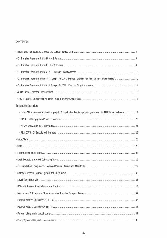
CONTENTS:
- Information to assist to choose the correct INPRO unit ............................................................................................ 5
- Oil Transfer Pressure Units GP N - 1 Pump ............................................................................................................. 6
- Oil Transfer Pressure Units GP GE - 2 Pumps .......................................................................................................... 8
- Oil Transfer Pressure Units GP N - GC High Flow Systems ....................................................................................... 10
- Oil Transfer Pressure Units FP 1 Pump - FP ZW 2 Pumps System for Tank to Tank Transferring .............................. 12
- Oil Transfer Pressure Units RL 1 Pump - RL ZW 2 Pumps Ring transferring ............................................................ 14
- ATAM Diesel Transfer Pressure Set...... .....................................................................................................................16
- CAG + Control Cabinet for Multiple Backup Power Generators...... ...........................................................................17
Schematic Examples:
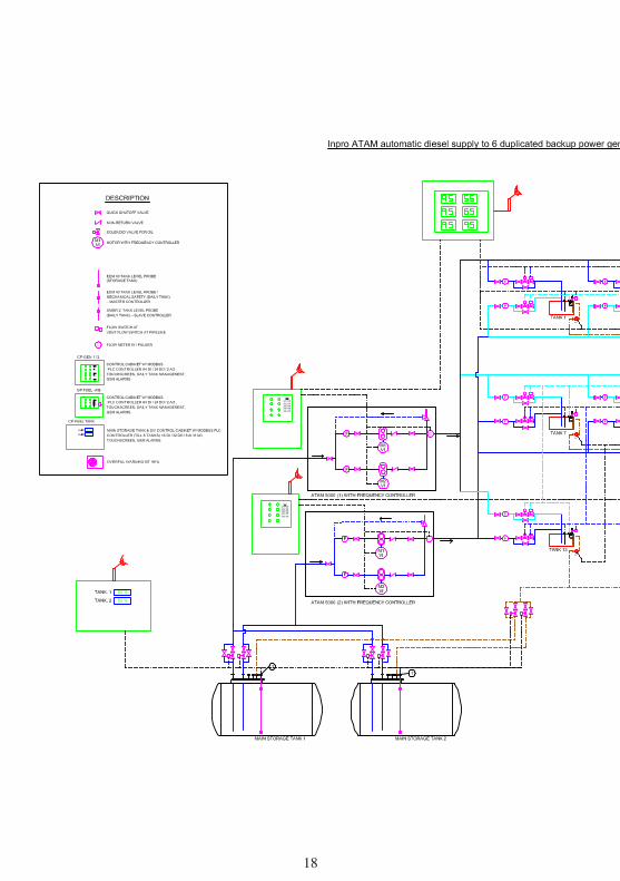
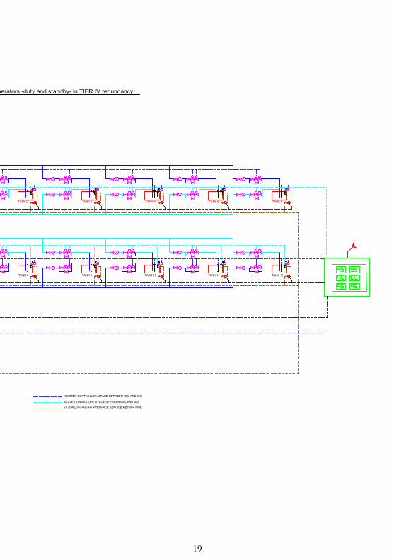
- Inpro ATAM automatic diesel supply to 6 duplicated backup power generators in TIER IV redundancy...... ...........18
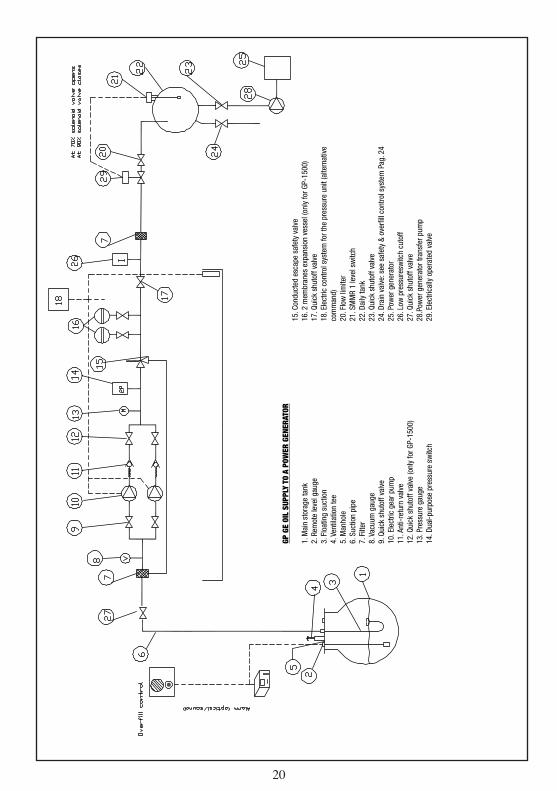
- GP GE Oil Supply to a Power Generator .............................................................................................................. 20
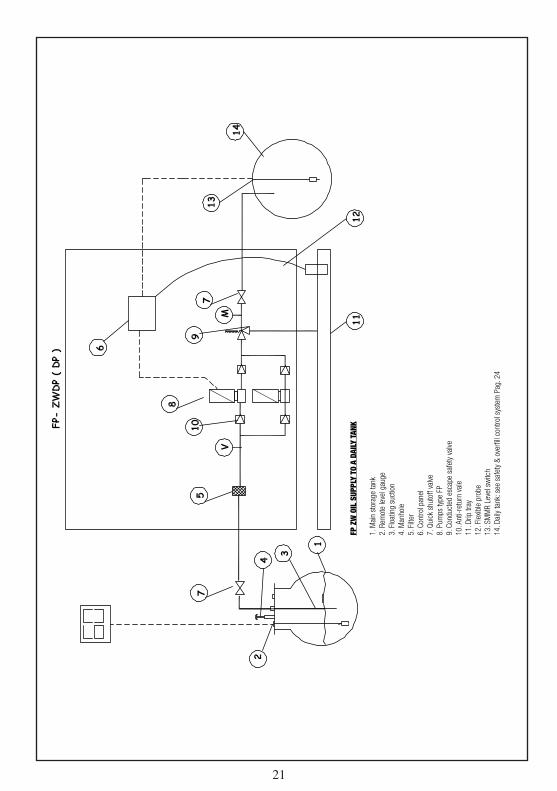
- FP ZW Oil Supply to a daily tank ........................................................................................................................ 21
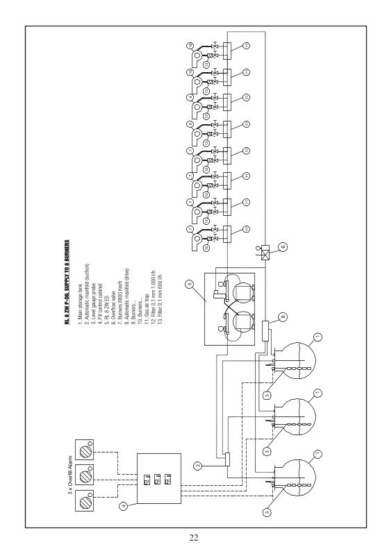
- RL 8 ZW P-Oil Supply to 8 burners .................................................................................................................... 22
- MicroSafa ............................................................................................................................................................... 23
- Safa ....................................................................................................................................................................... 25
- Filtering Kits and Filters .......................................................................................................................................... 27
- Leak Detectors and Oil Collecting Trays .................................................................................................................. 28
- Oil Installation Equipment / Solenoid Valves / Automatic Manifolds ......................................................................... 29
- Safety + Overfill Control System for Daily Tanks ..................................................................................................... 30
- Level Switch SMMR ............................................................................................................................................... 31
- EDM-40 Remote Level Gauge and Control .............................................................................................................. 32
- Mechanical & Electronic Flow Meters for Transfer Pumps / Pulsers ......................................................................... 34
- Fuel Oil Meters Contoil VZO 15…50 ....................................................................................................................... 35
- Fuel Oil Meters Contoil VZF 15…50 ........................................................................................................................ 36
- Piston, rotary and manual pumps............................................................................................................................ 37
- Pump System Request Questionnaire...................................................................................................................... 38
4 5
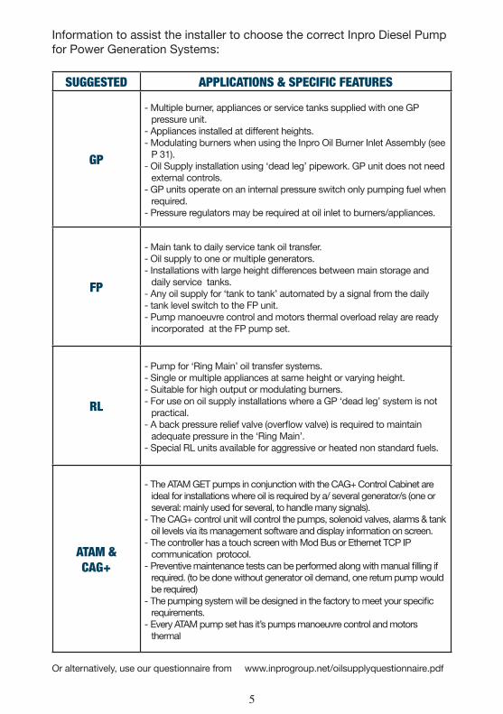
SUGGESTED APPLICATIONS & SPECIFIC FEATURES
GP
- Multiple burner, appliances or service tanks supplied with one GP pressure unit.
- Appliances installed at different heights.- Modulating burners when using the Inpro Oil Burner Inlet Assembly (see
P 31).- Oil Supply installation using ‘dead leg’ pipework. GP unit does not need
external controls.- GP units operate on an internal pressure switch only pumping fuel when
required.- Pressure regulators may be required at oil inlet to burners/appliances.
FP
- Main tank to daily service tank oil transfer.- Oil supply to one or multiple generators.- Installations with large height differences between main storage and
daily service tanks.- Any oil supply for ‘tank to tank’ automated by a signal from the daily- tank level switch to the FP unit.- Pump manoeuvre control and motors thermal overload relay are ready
incorporated at the FP pump set.
RL
- Pump for ‘Ring Main’ oil transfer systems.- Single or multiple appliances at same height or varying height.- Suitable for high output or modulating burners.- For use on oil supply installations where a GP ‘dead leg’ system is not
practical.- A back pressure relief valve (overflow valve) is required to maintain
adequate pressure in the ‘Ring Main’.- Special RL units available for aggressive or heated non standard fuels.
ATAM &CAG+
- The ATAM GET pumps in conjunction with the CAG+ Control Cabinet are ideal for installations where oil is required by a/ several generator/s (one or several: mainly used for several, to handle many signals).
- The CAG+ control unit will control the pumps, solenoid valves, alarms & tank oil levels via its management software and display information on screen.
- The controller has a touch screen with Mod Bus or Ethernet TCP IP communication protocol.
- Preventive maintenance tests can be performed along with manual filling if required. (to be done without generator oil demand, one return pump would be required)
- The pumping system will be designed in the factory to meet your specific requirements.
- Every ATAM pump set has it’s pumps manoeuvre control and motors thermal
Or alternatively, use our questionnaire from www.inprogroup.net/oilsupplyquestionnaire.pdf
Information to assist the installer to choose the correct Inpro Diesel Pump for Power Generation Systems:
6
CONTROLASSEMBLY
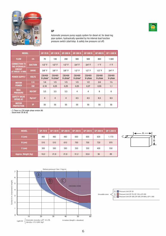
MODEL GP-70 N GP-130 N GP-200 N GP-300 N GP-500 N GP-800 N GP-1.500 N
A (cm) 460 460 460 600 600 620 1.170
B (cm) 510 510 610 700 700 720 970
C (cm) 300 300 300 350 350 400 550
Approx. Weight (kg) 18,2 21,8 21,8 31,2 33,6 36 89
Pressure Unit GP-30
Pressure Unit GP-70, GP-130 y GP-200Pressure Unit GP-300, GP-500, GP-800 y GP-1.500
Unusable zone
Delivery pressure 2 bar / 2 kg/cm2
Suct
ion
in m
. (m
anom
etric
hei
ght)
kinematic viscosity= ү37 ~4 c St.density= √15~0,841 kg/l
Light Oil In meters (length + elevation)
UNUSABLE ZONE
MODEL GP-70 N GP-130 N GP-200 N GP-300 N GP-500 N GP-800 N GP-1.500 N
FLOW l/h 70 130 200 300 500 800 1.500
CONNECTION TO THE HYDRAULIC
CIRCUIT(Ø THREAD / Ø MM)
SUCTION 1/2” F 1/2” F 1/2” F 3/4” F 3/4” F 1” F 1” F
DRIVE 3/8” F 3/8” F 3/8” F 1/2” F 1/2” F 1/2” F 3/4” F
POWER SUPPLY VOLTS230/400
tri-phase*230/400
tri-phase*230/400
tri-phase*230/400
tri-phase*230/400 tri-phase
230/400 tri-phase
230/400 tri-phase
MOTORPOWER
C.V. 1/4 1/3 1/3 1/3 1/2 3/4 1½
KW 0,18 0,25 0,25 0,25 0,37 0,55 1,1
MAX.PRESSURE
KG/CM2 3,5 3,5 3,5 4 4 6 6
SAFETY VALVE OPENS AT:
Kg/cm2 4 4 4 4,5 4,5 6,5 6,5
MOTORPROTECTION
IP 55 55 55 55 55 55 55
- (*) There is a 230 single-phase version (W)- Sound level: 58 db (A)
GP
Automatic pressure pump supply system for diesel oil, for dead-leg pipe system, hydraulically operated by his internal dual function pressure switch (start/stop & safety low pressure cut off)
6 7
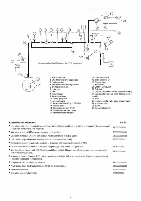
The elements from 7 to 18 belong to the INPRO pressure unit. G.E.
1. Main storage tank2. EDM-40 Remote level gauge probe3. Floating suction4. EDM-40 Remote level gauge screen5. Overfill prevention kit6. Intake pipe7. Filter8. Vacuum gauge9. Quick shutoff valve10. Electric gear pump11. Anti-return valve12. Quick shutoff valve (Only for GP-1500)13. Pressure gauge14. Dual purpose pressure switch15. Conducted escape safety valve16. Membrane expansion vessel
17. Quick shutoff valve18. Motor protection GP19. Solenoid valve20. Flow limiter21. SMMR 1 Level switch22. Daily tank23. Drip tray (included for GP-800 and above models)24. Leak detection (included for GP-800 and above models)25. Filter26. Pressure reduction valve (using pressure gauge)27. Non-return valve28. Burner29. Burner inlet assembly
Accessories and adaptations Art. Nr.
• Free voltage relay output to control from centralised Building Management System, in kit 3, 4 or 6 signals (2-thermal, motors 1 or 2 ON, low pressure and Leak safety ON).
21000000000---
• GSM alarm system by SMS messages, or connection to modem. 28000000000000
• Adaptation of Pressure Group for high pressure, working conditions of up to 6 Kg/cm2 21000000001300
• Leak collector trays with infrared detectors (standard in GP-800 and GP-1500). 2309000000----
• Modifications to adapt to specifically regulated environments with tropicalised equipment or ATEX.
• Solenoid valves with flow limiters, to automate filling in supply tanks for electrical generators. 2303000005----
• Soundproof sheet cabinets with UNE-25 poly-pyramid foam and lock. Manufactured with no back and made-to-measure for each Pressure Group model.
2102000000----
• Assembly of Pressure Groups in IP-55 cabinets for outdoor installation with exterior suction and drive pipe couplings, electric connection presses and ventilation grills.
• Line pressure switch to signal low pressure. 22030000002201
• Power supply failure safety system (timer deferred low pressure stop.) 21000000002300
• Burner inlet assembly 23010000000---
• Modulating burner inlet assembly 23010000001---
8
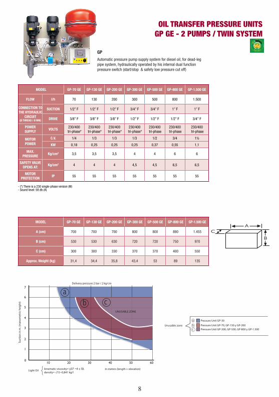
OIL TRANSFER PRESSURE UNITSGP GE - 2 PUMPS / TWIN SYSTEM
MODEL GP-70 GE GP-130 GE GP-200 GE GP-300 GE GP-500 GE GP-800 GE GP-1.500 GE
FLOW l/h 70 130 200 300 500 800 1.500
CONNECTION TO THE HYDRAULIC
CIRCUIT(Ø THREAD / Ø MM)
SUCTION 1/2” F 1/2” F 1/2” F 3/4” F 3/4” F 1” F 1” F
DRIVE 3/8” F 3/8” F 3/8” F 1/2” F 1/2” F 1/2” F 3/4” F
POWER SUPPLY
VOLTS230/400
tri-phase*230/400
tri-phase*230/400
tri-phase*230/400
tri-phase*230/400 tri-phase
230/400 tri-phase
230/400 tri-phase
MOTORPOWER
C.V. 1/4 1/3 1/3 1/3 1/2 3/4 1½
KW 0,18 0,25 0,25 0,25 0,37 0,55 1,1
MAX.PRESSURE
Kg/cm2 3,5 3,5 3,5 4 4 6 6
SAFETY VALVE OPENS AT:
Kg/cm2 4 4 4 4,5 4,5 6,5 6,5
MOTORPROTECTION
IP 55 55 55 55 55 55 55
- (*) There is a 230 single-phase version (W)- Sound level: 58 db (A)
MODEL GP-70 GE GP-130 GE GP-200 GE GP-300 GE GP-500 GE GP-800 GE GP-1.500 GE
A (cm) 700 700 700 800 800 890 1.455
B (cm) 530 530 630 720 720 750 970
C (cm) 300 300 330 370 370 400 550
Approx. Weight (kg) 31,4 34,4 35,8 43,4 53 89 135
CONTROLASSEMBLY
Pressure Unit GP-30
Pressure Unit GP-70, GP-130 y GP-200Pressure Unit GP-300, GP-500, GP-800 y GP-1.500
Unusable zone
Delivery pressure 2 bar / 2 kg/cm2
Suct
ion
in m
. (m
anom
etric
hei
ght)
kinematic viscosity= ү37 ~4 c St.density= √15~0,841 kg/l
Light Oil In meters (length + elevation)
UNUSABLE ZONE
GP
Automatic pressure pump supply system for diesel oil, for dead-leg pipe system, hydraulically operated by his internal dual function pressure switch (start/stop & safety low pressure cut off)
8 9
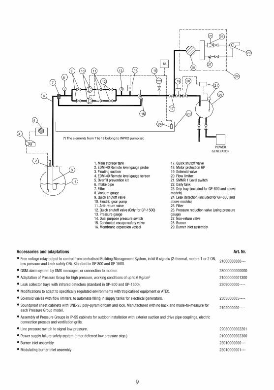
(*) The elements from 7 to 18 belong to INPRO pump set
POWER GENERATOR
1. Main storage tank2. EDM-40 Remote level gauge probe3. Floating suction4. EDM-40 Remote level gauge screen5. Overfill prevention kit6. Intake pipe7. Filter8. Vacuum gauge9. Quick shutoff valve10. Electric gear pump11. Anti-return valve12. Quick shutoff valve (Only for GP-1500)13. Pressure gauge14. Dual purpose pressure switch15. Conducted escape safety valve16. Membrane expansion vessel
17. Quick shutoff valve18. Motor protection GP19. Solenoid valve20. Flow limiter21. SMMR 1 Level switch22. Daily tank23. Drip tray (included for GP-800 and above models)24. Leak detection (included for GP-800 and above models)25. Filter26. Pressure reduction valve (using pressure gauge)27. Non-return valve28. Burner29. Burner inlet assembly
Accessories and adaptations Art. Nr.
• Free voltage relay output to control from centralised Building Management System, in kit 6 signals (2-thermal, motors 1 or 2 ON, low pressure and Leak safety ON). Standard in GP 800 and GP 1500.
21000000000---
• GSM alarm system by SMS messages, or connection to modem. 28000000000000
• Adaptation of Pressure Group for high pressure, working conditions of up to 6 Kg/cm2 21000000001300
• Leak collector trays with infrared detectors (standard in GP-800 and GP-1500). 2309000000----
• Modifications to adapt to specifically regulated environments with tropicalised equipment or ATEX.
• Solenoid valves with flow limiters, to automate filling in supply tanks for electrical generators. 2303000005----
• Soundproof sheet cabinets with UNE-25 poly-pyramid foam and lock. Manufactured with no back and made-to-measure for each Pressure Group model.
2102000000----
• Assembly of Pressure Groups in IP-55 cabinets for outdoor installation with exterior suction and drive pipe couplings, electric connection presses and ventilation grills.
• Line pressure switch to signal low pressure. 22030000002201
• Power supply failure safety system (timer deferred low pressure stop.) 21000000002300
• Burner inlet assembly 23010000000---
• Modulating burner inlet assembly 23010000001---
10
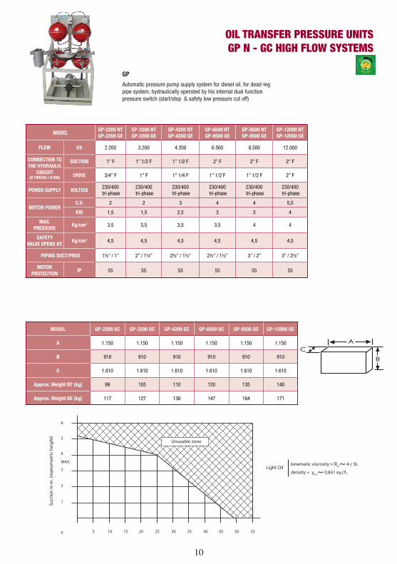
OIL TRANSFER PRESSURE UNITSGP N - GC HIGH FLOW SYSTEMS
MODELGP-2200 NTGP-2200 GE
GP-3200 NTGP-3200 GE
GP-4200 NTGP-4200 GE
GP-6500 NTGP-6500 GE
GP-8500 NTGP-8500 GE
GP-12000 NTGP-12000 GE
FLOW l/h 2.200 3.200 4.200 6.500 8.500 12.000
CONNECTION TO THE HYDRAULIC
CIRCUIT(Ø THREAD / Ø MM)
SUCTION 1” F 1” 1/2 F 1” 1/2 F 2” F 2” F 2” F
DRIVE 3/4” F 1” F 1” 1/4 F 1” 1/2 F 1” 1/2 F 2” F
POWER SUPPLY VOLTIOS230/400 tri-phase
230/400 tri-phase
230/400 tri-phase
230/400 tri-phase
230/400 tri-phase
230/400 tri-phase
MOTOR POWERC.V. 2 2 3 4 4 5,5
KW 1,5 1,5 2,2 3 3 4
MAX.PRESSURE
Kg/cm2 3,5 3,5 3,5 3,5 4 4
SAFETYVALVE OPENS AT:
Kg/cm2 4,5 4,5 4,5 4,5 4,5 4,5
PIPING SUCT/PRES 1½” / 1” 2” / 1¼” 2½” / 1½” 2½” / 1½” 3” / 2” 3” / 2½”
MOTORPROTECTION
IP 55 55 55 55 55 55
MODEL GP-2200 GC GP-3200 GC GP-4200 GC GP-6500 GC GP-8500 GC GP-12000 GC
A 1.150 1.150 1.150 1.150 1.150 1.150
B 910 910 910 910 910 910
C 1.610 1.610 1.610 1.610 1.610 1.610
Approx. Weight NT (kg) 99 105 110 120 135 140
Approx. Weight GE (kg) 117 127 136 147 164 171
CONTROLASSEMBLY
Unusable zone
0
1
2
3
MAX.
4
5
6
5 10 15 20 25 30 35 40 45 50 55
Light Oil kinematic viscosity = �37~ 4 c St.
density = χ15 ~ 0,841 κγ./Λ.
Suct
ion
in m
. (m
anom
etric
hei
ght)
GP
Automatic pressure pump supply system for diesel oil, for dead-leg pipe system, hydraulically operated by his internal dual function pressure switch (start/stop & safety low pressure cut off)
10 11
� � ��
�
�
�
�
�
�
�
��
� �� �� �� �� �� ��
��
��
��
����
�� ����
��
�� ��
��
��
����
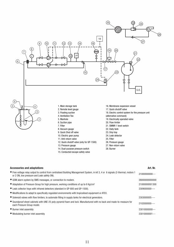
1. Main storage tank2. Remote level gauge3. Floating suction4. Ventilation Tee5. Manhole6. Suction pipe7. Filter8. Vacuum gauge9. Quick Shut off valve10. Electric gear pump11. Anti-return valve12. Quick shutoff valve (only for GP-1500)13. Pressure gauge14. Dual-purpose pressure switch15. Conducted escape safety valve
16. Membrane expansion vessel17. Quick shutoff valve18. Electric control system for the pressure unit (alternative command)19. Electrically operated valve20. Flow limiter21. SMMR 1 level switch22. Daily tank23. Drip tray24. Leak detector25. Filter26. Pressure gauge27. Non-return valve28. Burner
Accessories and adaptations Art. Nr.
• Free voltage relay output to control from centralised Building Management System, in kit 3, 4 or 6 signals (2-thermal, motors 1 or 2 ON, low pressure and Leak safety ON).
21000000000---
• GSM alarm system by SMS messages, or connection to modem. 28000000000000
• Adaptation of Pressure Group for high pressure, working conditions of up to 6 Kg/cm2 21000000001300
• Leak collector trays with infrared detectors (standard in GP-800 and GP-1500). 2309000000----
• Modifications to adapt to specifically regulated environments with tropicalised equipment or ATEX.
• Solenoid valves with flow limiters, to automate filling in supply tanks for electrical generators. 2303000005----
• Soundproof sheet cabinets with UNE-25 poly-pyramid foam and lock. Manufactured with no back and made-to-measure for each Pressure Group model.
2102000000----
• Burner inlet assembly 23010000000---
• Modulating burner inlet assembly 23010000001---
12
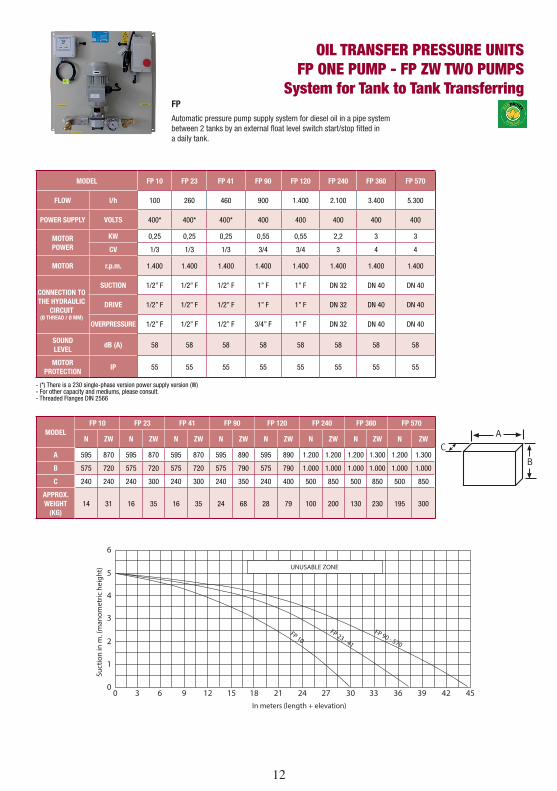
OIL TRANSFER PRESSURE UNITSFP ONE PUMP - FP ZW TWO PUMPS
System for Tank to Tank Transferring
UNUSABLE ZONE
FP 10FP 23 - 41
FP 90 - 570
6
5
4
3
2
1
00 3 6 9 12 15 18 21 24 27 30 33 36 39 42 45
Suct
ion
in m
. (m
anom
etric
hei
ght)
In meters (length + elevation)
MODELFP 10 FP 23 FP 41 FP 90 FP 120 FP 240 FP 360 FP 570
N ZW N ZW N ZW N ZW N ZW N ZW N ZW N ZW
A 595 870 595 870 595 870 595 890 595 890 1.200 1.200 1.200 1.300 1.200 1.300
B 575 720 575 720 575 720 575 790 575 790 1.000 1.000 1.000 1.000 1.000 1.000
C 240 240 240 300 240 300 240 350 240 400 500 850 500 850 500 850
APPROX. WEIGHT
(KG)14 31 16 35 16 35 24 68 28 79 100 200 130 230 195 300
MODEL FP 10 FP 23 FP 41 FP 90 FP 120 FP 240 FP 360 FP 570
FLOW l/h 100 260 460 900 1.400 2.100 3.400 5.300
POWER SUPPLY VOLTS 400* 400* 400* 400 400 400 400 400
MOTORPOWER
KW 0,25 0,25 0,25 0,55 0,55 2,2 3 3
CV 1/3 1/3 1/3 3/4 3/4 3 4 4
MOTOR r.p.m. 1.400 1.400 1.400 1.400 1.400 1.400 1.400 1.400
CONNECTION TO THE HYDRAULIC
CIRCUIT(Ø THREAD / Ø MM)
SUCTION 1/2” F 1/2” F 1/2” F 1” F 1” F DN 32 DN 40 DN 40
DRIVE 1/2” F 1/2” F 1/2” F 1” F 1” F DN 32 DN 40 DN 40
OVERPRESSURE 1/2” F 1/2” F 1/2” F 3/4” F 1” F DN 32 DN 40 DN 40
SOUNDLEVEL
dB (A) 58 58 58 58 58 58 58 58
MOTORPROTECTION
IP 55 55 55 55 55 55 55 55
- (*) There is a 230 single-phase version power supply version (W)- For other capacity and mediums, please consult.- Threaded Flanges DIN 2566
FP
Automatic pressure pump supply system for diesel oil in a pipe system between 2 tanks by an external float level switch start/stop fitted in a daily tank.
12 13
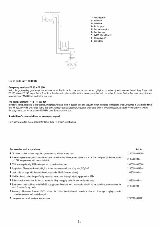
7
3
9
8
6
2
1
4
5
List of parts in FP MODELS
One pump versions FP 10 - FP 570Motor, flange, coupling, gear pump, overpressure valve, filter in suction side and vacuum meter, rigid pipe connections (steel), mounted in wall fixing frame until FP 120. Above FP 240, angle frame floor deck. Ready electrical assembly, switch, motor protection and connection for Level Switch. For easy connection we recommended SMMR1 level switch for your tank.
Two pumps versions FP 10 - FP 570 ZW2 motors, flange, coupling, 2 gear pumps, overpressure valve, filter in suction side and vacuum meter, rigid pipe connections (steel), mounted in wall fixing frame until FP 120. Above FP 240, angle frame floor deck. Ready electrical assembly, electrical alternative switch, motor protection, and connection for Level Switch.For easy connection we recommend SMMR1 Level Switch for your tank.
Special Non-Ferrous metal free versions upon request.
For higher viscosities please consult for the suitable FP system specification.
Accessories and adaptations Art. Nr.
• Oil failure control system, to protect gears running with an empty tank. 21000000001500
• Free voltage relay output to control from centralised Building Management System, in kit 3, 4 or 6 signals (2-thermal, motors 1 or 2 ON, low pressure and Leak safety ON).
21000000000---
• GSM alarm system by SMS messages, or connection to modem. 28000000000000
• Adaptation of Pressure Group for high pressure, working conditions of up to 4,5 Kg/cm2 210000000013--
• Leak collector trays with infrared detectors (standard in FP 240 and above) 2309000000----
• Modifications to adapt to specifically regulated environments (tropicalised equipment or ATEX.)
• Solenoid valves with flow limiters, to automate filling in supply tanks for electrical generators. 2303000005----
• Soundproof sheet cabinets with UNE-25 poly-pyramid foam and lock. Manufactured with no back and made-to-measure for each Pressure Group model.
2102000000----
• Assembly of Pressure Groups in IP-55 cabinets for outdoor installation with exterior suction and drive pipe couplings, electric connection presses and ventilation grills.
• Line pressure switch to signal low pressure. 22030000002201
1.- Pump Type FP2.- Main tank3.- Daily tank4.- Suction pipe5.- Overpressure pipe6.- Overflow pipe7.- SMMR 1 Level Switch8.- Oil supply pipe9.- Control line
14
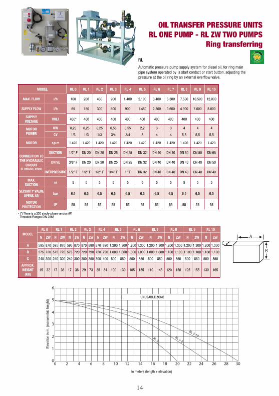
OIL TRANSFER PRESSURE UNITSRL ONE PUMP - RL ZW TWO PUMPS
Ring transferring
6
5
4
3
2
1
00 2 4 6 8 10 12 14 16 18 20 22 24 26 28 30
RL 0RL 1-2
RL 3-10
UNUSABLE ZONE
Elev
atio
n in
m. (
man
omet
ric h
eigh
t)
In meters (length + elevation)
MODEL RL 0 RL 1 RL 2 RL 3 RL 4 RL 5 RL 6 RL 7 RL 8 RL 9 RL 10
MAX. FLOW l/h 100 260 460 900 1.400 2.100 3.400 5.300 7.500 10.500 12.000
SUPPLY FLOW l/h 65 150 300 600 900 1.450 2.300 3.600 4.900 7.000 8.000
SUPPLY VOLTAGE
VOLT 400* 400 400 400 400 400 400 400 400 400 400
MOTORPOWER
KW 0,25 0,25 0,25 0,55 0,55 2,2 3 3 4 4 4
CV 1/3 1/3 1/3 3/4 3/4 3 4 4 5,5 5,5 5,5
MOTOR r.p.m 1.420 1.420 1.420 1.420 1.420 1.420 1.420 1.420 1.420 1.420 1.420
CONNECTION TO THE HYDRAULIC
CIRCUIT (Ø THREAD / Ø MM)
SUCTION 1/2” F DN 20 DN 20 DN 25 DN 25 DN 32 DN 40 DN 40 DN 50 DN 50 DN 65
DRIVE 3/8” F DN 20 DN 20 DN 25 DN 25 DN 32 DN 40 DN 40 DN 40 DN 40 DN 50
OVERPRESSURE 1/2” F 1/2” F 1/2” F 3/4” F 1” F DN 32 DN 40 DN 40 DN 40 DN 40 DN 40
MAX.SUCTION
m 5 5 5 5 5 5 5 5 5 5 5
SECURITY VALVE OPENS AT:
bar 6,5 6,5 6,5 6,5 6,5 6,5 6,5 6,5 6,5 6,5 6,5
MOTORPROTECTION
IP 55 55 55 55 55 55 55 55 55 55 55
- (*) There is a 230 single-phase version (W)- Threaded Flanges DIN 2566
MODELRL 0 RL 1 RL 2 RL 3 RL 4 RL 5 RL 6 RL 7 RL 8 RL 9 RL 10
N ZW N ZW N ZW N ZW N ZW N ZW N ZW N ZW N ZW N ZW N ZW
A 595 870 595 870 595 870 870 890 870 890 1.200 1.300 1.200 1.300 1.200 1.300 1.200 1.300 1.200 1.300 1.200 1.300
B 575 720 575 720 575 720 720 790 720 790 1.000 1.000 1.000 1.000 1.000 1.000 1.100 1.100 1.100 1.100 1.100 1.100
C 240 300 240 300 240 300 300 350 300 400 500 850 500 850 500 850 500 850 500 850 500 850
APPROX. WEIGHT
(KG)15 32 17 36 17 36 29 73 35 84 100 130 105 135 110 145 120 150 125 155 130 165
RL
Automatic pressure pump supply system for diesel oil, for ring main pipe system operated by a start contact or start button, adjusting the pressure at the oil ring by an external overflow valve.
14 15
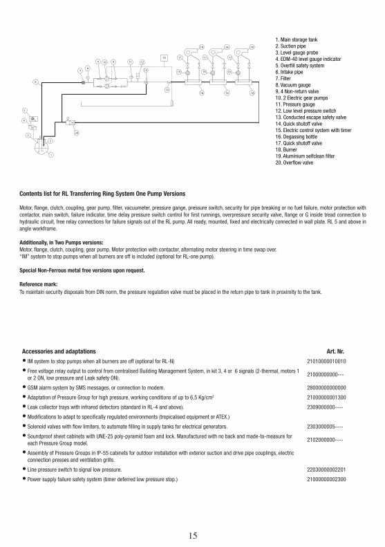
Contents list for RL Transferring Ring System One Pump Versions
Motor, flange, clutch, coupling, gear pump, filter, vacuumeter, pressure gange, pressure switch, security for pipe breaking or no fuel failure, motor protection with contactor, main switch, failure indicator, time delay pressure switch control for first runnings, overpressure security valve, flange or G inside tread connection to hydraulic circuit, free relay connections for failure signals out of the RL pump. All ready, mounted, fixed and electrically connected in wall plate. RL 5 and above in angle workframe.
Additionally, in Two Pumps versions:Motor, flange, clutch, coupling, gear pump, Motor protection with contactor, alternating motor steering in time swap over.“IM” system to stop pumps when all burners are off is included (optional for RL-one pump).
Special Non-Ferrous metal free versions upon request.
Reference mark:To maintain security disposals from DIN norm, the pressure regulation valve must be placed in the return pipe to tank in proximity to the tank.
1
2
3
4
5
6
78
9 910 11 12
13
14
15
16 16
17
18
19 19
17
18
19
17
18
20
Accessories and adaptations Art. Nr.
• IM system to stop pumps when all burners are off (optional for RL-N) 21010000010010
• Free voltage relay output to control from centralised Building Management System, in kit 3, 4 or 6 signals (2-thermal, motors 1 or 2 ON, low pressure and Leak safety ON).
21000000000---
• GSM alarm system by SMS messages, or connection to modem. 28000000000000
• Adaptation of Pressure Group for high pressure, working conditions of up to 6,5 Kg/cm2 21000000001300
• Leak collector trays with infrared detectors (standard in RL-4 and above). 2309000000----
• Modifications to adapt to specifically regulated environments (tropicalised equipment or ATEX.)
• Solenoid valves with flow limiters, to automate filling in supply tanks for electrical generators. 2303000005----
• Soundproof sheet cabinets with UNE-25 poly-pyramid foam and lock. Manufactured with no back and made-to-measure for each Pressure Group model.
2102000000----
• Assembly of Pressure Groups in IP-55 cabinets for outdoor installation with exterior suction and drive pipe couplings, electric connection presses and ventilation grills.
• Line pressure switch to signal low pressure. 22030000002201
• Power supply failure safety system (timer deferred low pressure stop.) 21000000002300
1. Main storage tank2. Suction pipe3. Level gauge probe4. EDM-40 level gauge indicator5. Overfill safety system6. Intake pipe7. Filter8. Vacuum gauge9. 4 Non-return valve10. 2 Electric gear pumps11. Pressure gauge12. Low level pressure switch13. Conducted escape safety valve14. Quick shutoff valve15. Electric control system with timer16. Degassing bottle17. Quick shutoff valve18. Burner19. Aluminium selfclean filter20. Overflow valve
16
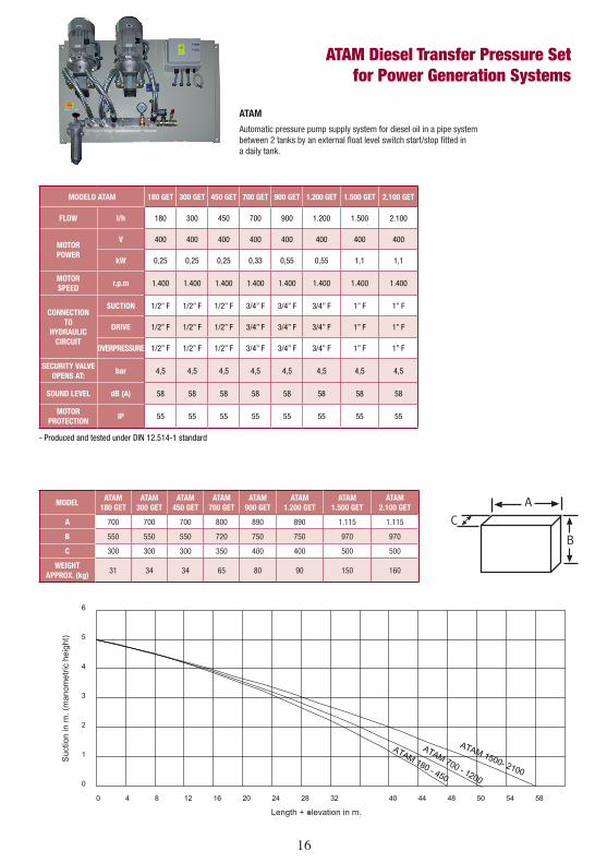
ATAM Diesel Transfer Pressure Setfor Power Generation Systems
Suc
tion
in m
. (m
anom
etric
hei
ght)
Length + elevation in m.
MODELATAM
180 GETATAM
300 GETATAM
450 GETATAM
700 GETATAM
900 GETATAM
1.200 GETATAM
1.500 GETATAM
2.100 GET
A 700 700 700 800 890 890 1.115 1.115
B 550 550 550 720 750 750 970 970
C 300 300 300 350 400 400 500 500
WEIGHTAPPROX. (kg)
31 34 34 65 80 90 150 160
MODELO ATAM 180 GET 300 GET 450 GET 700 GET 900 GET 1.200 GET 1.500 GET 2.100 GET
FLOW l/h 180 300 450 700 900 1.200 1.500 2.100
MOTORPOWER
V 400 400 400 400 400 400 400 400
kW 0,25 0,25 0,25 0,33 0,55 0,55 1,1 1,1
MOTORSPEED
r.p.m 1.400 1.400 1.400 1.400 1.400 1.400 1.400 1.400
CONNECTION TO
HYDRAULIC CIRCUIT
SUCTION 1/2” F 1/2” F 1/2” F 3/4” F 3/4” F 3/4” F 1” F 1” F
DRIVE 1/2” F 1/2” F 1/2” F 3/4” F 3/4” F 3/4” F 1” F 1” F
OVERPRESSURE 1/2” F 1/2” F 1/2” F 3/4” F 3/4” F 3/4” F 1” F 1” F
SECURITY VALVEOPENS AT:
bar 4,5 4,5 4,5 4,5 4,5 4,5 4,5 4,5
SOUND LEVEL dB (A) 58 58 58 58 58 58 58 58
MOTORPROTECTION
IP 55 55 55 55 55 55 55 55
- Produced and tested under DIN 12.514-1 standard
ATAM
Automatic pressure pump supply system for diesel oil in a pipe system between 2 tanks by an external float level switch start/stop fitted in a daily tank.
16 17
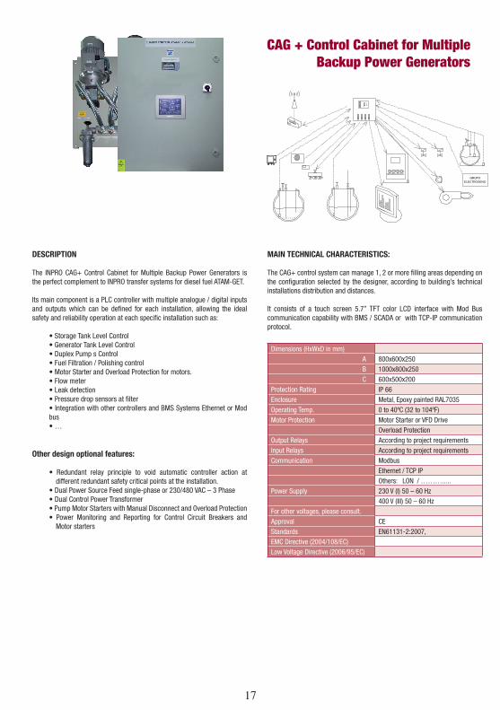
CAG + Control Cabinet for MultipleBackup Power Generators
DESCRIPTION
The INPRO CAG+ Control Cabinet for Multiple Backup Power Generators is the perfect complement to INPRO transfer systems for diesel fuel ATAM-GET.
Its main component is a PLC controller with multiple analogue / digital inputs and outputs which can be defined for each installation, allowing the ideal safety and reliability operation at each specific installation such as:
• Storage Tank Level Control• Generator Tank Level Control• Duplex Pump s Control• Fuel Filtration / Polishing control• Motor Starter and Overload Protection for motors.• Flow meter• Leak detection• Pressure drop sensors at filter• Integration with other controllers and BMS Systems Ethernet or Mod bus• …
Other design optional features:
• Redundant relay principle to void automatic controller action at different redundant safety critical points at the installation.
• Dual Power Source Feed single-phase or 230/480 VAC – 3 Phase• Dual Control Power Transformer• Pump Motor Starters with Manual Disconnect and Overload Protection• Power Monitoring and Reporting for Control Circuit Breakers and
Motor starters
MAIN TECHNICAL CHARACTERISTICS:
The CAG+ control system can manage 1, 2 or more filling areas depending on the configuration selected by the designer, according to building’s technical installations distribution and distances.
It consists of a touch screen 5.7” TFT color LCD interface with Mod Bus communication capability with BMS / SCADA or with TCP-IP communication protocol.
Dimensions (HxWxD in mm)A 800x600x250B 1000x800x250C 600x500x200
Protection Rating IP 66Enclosure Metal, Epoxy painted RAL7035Operating Temp. 0 to 40ºC (32 to 104ºF)Motor Protection Motor Starter or VFD Drive
Overload ProtectionOutput Relays According to project requirementsInput Relays According to project requirementsCommunication Modbus
Ethernet / TCP IPOthers: LON / ……….....
Power Supply 230 V (I) 50 – 60 Hz400 V (III) 50 – 60 Hz
For other voltages, please consult.Approval CEStandards EN61131-2:2007,EMC Directive (2004/108/EC)Low Voltage Directive (2006/95/EC)
18
18 19
20
GP G
E OI
L SU
PPLY
TO
A PO
WER
GEN
ERAT
OR
1. M
ain
stor
age
tank
2. R
emot
e le
vel g
auge
3. F
loat
ing
suct
ion
4. V
entil
atio
n te
e5.
Man
hole
6. S
uctio
n pi
pe7.
Filt
er8.
Vac
uum
gau
ge9.
Qui
ck s
huto
ff va
lve
10. E
lect
ric g
ear p
ump
11. A
nti-r
etur
n va
lve
12. Q
uick
shu
toff
valv
e (o
nly
for G
P-15
00)
13. P
ress
ure
gaug
e14
. Dua
l-pur
pose
pre
ssur
e sw
itch
15. C
ondu
cted
esc
ape
safe
ty v
alve
16. 2
mem
bran
es e
xpan
sion
ves
sel (
only
for G
P-15
00)
17. Q
uick
shu
toff
valv
e18
. Ele
ctric
con
trol s
yste
m fo
r the
pre
ssur
e un
it (a
ltern
ativ
e co
mm
and)
20. F
low
lim
iter
21. S
MM
R 1
leve
l sw
itch
22. D
aily
tank
23. Q
uick
shu
toff
valv
e24
. Dra
in v
alve
: see
saf
ety
& ov
erfil
l con
trol s
yste
m P
ag. 2
425
. Pow
er g
ener
ator
26. L
ow p
ress
ures
witc
h cu
toff
27. Q
uick
shu
toff
valv
e28
.Pow
er g
ener
ator
tran
sfer
pum
p29
. Ele
ctric
ally
ope
rate
d va
lve
20 21
FP Z
W O
IL S
UPPL
Y TO
A D
AILY
TAN
K
1. M
ain
stor
age
tank
2. R
emot
e le
vel g
auge
3. F
loat
ing
suct
ion
4. M
anho
le5.
Filt
er6.
Con
trol p
anel
7. Q
uick
shu
toff
valve
8. P
umps
type
FP
9. C
ondu
cted
esc
ape
safe
ty v
alve
10. A
nti-r
etur
n va
le11
. Drip
tray
12. F
lexib
le p
robe
13. S
MM
R Le
vel s
witc
h14
. Dai
ly ta
nk: s
ee s
afet
y &
over
fill c
ontro
l sys
tem
Pag
. 24
22
3 x
Ove
rfill
Ala
rmRL
8 Z
W P
-OIL
SUP
PLY
TO 8
BUR
NERS
1. M
ain
stor
age
tank
2. A
utom
atic
man
ifold
(suc
tion)
3. L
evel
gau
ge p
robe
4. F
ill co
ntro
l cab
inet
5.
RL
8 ZW
ES
6. O
verfl
ow v
alve
7. B
urne
rs 8
800
Kw/h
8. A
utom
atic
man
ifold
(driv
e)9.
Bur
ners
...10
. Bur
ners
...11
. Gas
air
trap
12. F
ilter
0,1
mm
1.0
00 l/
h13
. Filt
er 0
,1 m
m 6
00 l/
h
22 23
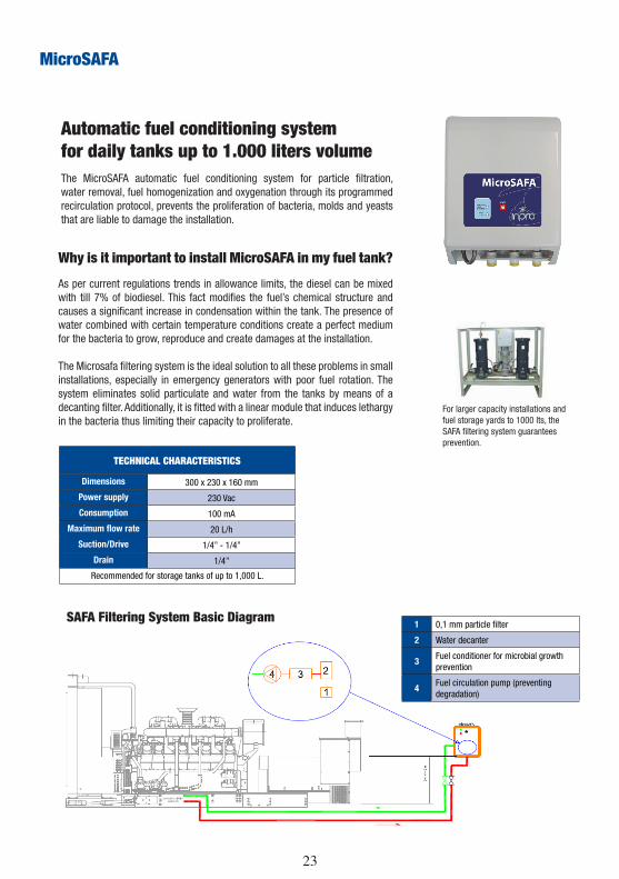
Why is it important to install MicroSAFA in my fuel tank?
As per current regulations trends in allowance limits, the diesel can be mixed with till 7% of biodiesel. This fact modifies the fuel’s chemical structure and causes a significant increase in condensation within the tank. The presence of water combined with certain temperature conditions create a perfect medium for the bacteria to grow, reproduce and create damages at the installation.
The Microsafa filtering system is the ideal solution to all these problems in small installations, especially in emergency generators with poor fuel rotation. The system eliminates solid particulate and water from the tanks by means of a decanting filter. Additionally, it is fitted with a linear module that induces lethargy in the bacteria thus limiting their capacity to proliferate.
For larger capacity installations and fuel storage yards to 1000 lts, the SAFA filtering system guarantees prevention.
Automatic fuel conditioning system for daily tanks up to 1.000 liters volumeThe MicroSAFA automatic fuel conditioning system for particle filtration, water removal, fuel homogenization and oxygenation through its programmed recirculation protocol, prevents the proliferation of bacteria, molds and yeasts that are liable to damage the installation.
SAFA Filtering System Basic Diagram
TECHNICAL CHARACTERISTICS
Dimensions 300 x 230 x 160 mm
Power supply 230 Vac
Consumption 100 mA
Maximum flow rate 20 L/h
Suction/Drive 1/4” - 1/4”
Drain 1/4”
Recommended for storage tanks of up to 1,000 L.
1 0,1 mm particle filter
2 Water decanter
3Fuel conditioner for microbial growth prevention
4Fuel circulation pump (preventing degradation)
MicroSAFA
24
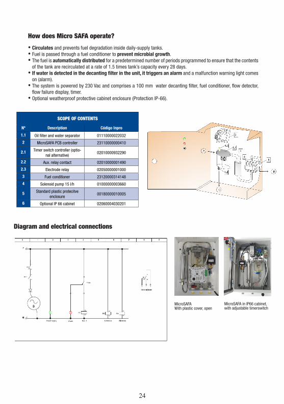
Diagram and electrical connections
MicroSAFAWith plastic cover, open
MicroSAFA in IP66 cabinet,with adjustable timerswitch
How does Micro SAFA operate?
• Circulates and prevents fuel degradation inside daily-supply tanks. • Fuel is passed through a fuel conditioner to prevent microbial growth.• The fuel is automatically distributed for a predetermined number of periods programmed to ensure that the contents
of the tank are recirculated at a rate of 1.5 times tank’s capacity every 28 days.• If water is detected in the decanting filter in the unit, it triggers an alarm and a malfunction warning light comes
on (alarm).• The system is powered by 230 Vac and comprises a 100 mm water decanting filter, fuel conditioner, flow detector,
flow failure display, timer. • Optional weatherproof protective cabinet enclosure (Protection IP-66).
SCOPE OF CONTENTS
Nº Description Código Inpro
1.1 Oil filter and water separator 01110000022032
2 MicroSAFA PCB controller 23110000000410
2.1 Timer switch controller (optio-nal alternative)
02010000932290
2.2 Aux. relay contact 02010000001490
2.3 Electrode relay 02050000001000
3 Fuel conditioner 23120000314148
4 Solenoid pump 15 l/h 01000000003660
5 Standard plastic protecitve enclosure
00180000010005
6 Optional IP 66 cabinet 02060004030201
24 25
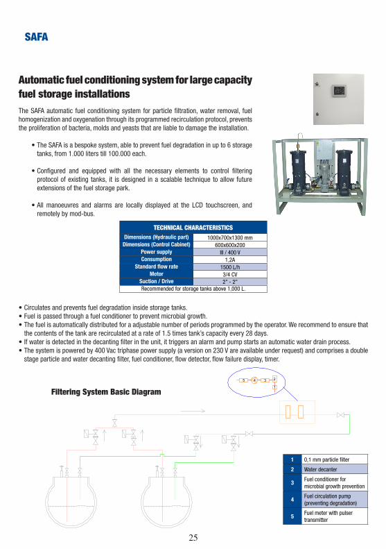
Automatic fuel conditioning system for large capacity fuel storage installationsThe SAFA automatic fuel conditioning system for particle filtration, water removal, fuel homogenization and oxygenation through its programmed recirculation protocol, prevents the proliferation of bacteria, molds and yeasts that are liable to damage the installation.
• The SAFA is a bespoke system, able to prevent fuel degradation in up to 6 storage tanks, from 1.000 liters till 100.000 each.
• Configured and equipped with all the necessary elements to control filtering protocol of existing tanks, it is designed in a scalable technique to allow future extensions of the fuel storage park.
• All manoeuvres and alarms are locally displayed at the LCD touchscreen, and remotely by mod-bus.
TECHNICAL CHARACTERISTICSDimensions (Hydraulic part) 1000x700x1300 mm
Dimensions (Control Cabinet) 600x600x200Power supply III / 400 VConsumption 1,2A
Standard flow rate 1500 L/hMotor 3/4 CV
Suction / Drive 2” - 2”Recommended for storage tanks above 1,000 L.
• Circulates and prevents fuel degradation inside storage tanks. • Fuel is passed through a fuel conditioner to prevent microbial growth.• The fuel is automatically distributed for a adjustable number of periods programmed by the operator. We recommend to ensure that
the contents of the tank are recirculated at a rate of 1.5 times tank’s capacity every 28 days.• If water is detected in the decanting filter in the unit, it triggers an alarm and pump starts an automatic water drain process.• The system is powered by 400 Vac triphase power supply (a version on 230 V are available under request) and comprises a double
stage particle and water decanting filter, fuel conditioner, flow detector, flow failure display, timer.
1 0,1 mm particle filter
2 Water decanter
3Fuel conditioner for microbial growth prevention
4Fuel circulation pump (preventing degradation)
5Fuel meter with pulser transmitter
Filtering System Basic Diagram
SAFA
26
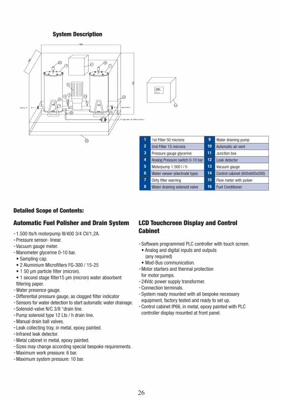
Automatic Fuel Polisher and Drain System
-1.500 lts/h motorpump III/400 3/4 CV/1,2A. -Pressure sensor- linear. -Vacuum gauge meter. -Manometer glycerine 0-10 bar.• Sampling cap.• 2 Aluminium Microfilters FG-300 / 15-25• 1 50 μm particle filter (micron).• 1 second stage filter15 μm (micron) water absorbent filtering paper. -Water presence gauge. -Differential pressure gauge, as clogged filter indicator -Sensors for water detection to start automatic water drainage. -Solenoid-valve N/C 3/8 “drain line. -Pump solenoid type 12 Lts / h drain line. -Manual drain ball valves. -Leak collecting tray, in metal, epoxy painted. - Infrared leak detector. -Metal cabinet in metal, epoxy painted. -Sizes may change according special bespoke requirements. -Maximum work pressure: 6 bar. -Maximum system pressure: 10 bar.
LCD Touchcreen Display and Control Cabinet
-Software programmed PLC controller with touch screen.• Analog and digital inputs and outputs
(any required)• Mod-Bus communication. -Motor starters and thermal protection for motor pumps. -24Vdc power supply transformer. -Connection terminals. -System ready mounted with all bespoke necessary equipment, factory tested and ready to set up. -Control cabinet IP66, in metal, epoxy painted with PLC controller display mounted at front panel.
1 1st Filter 50 microns 9 Water draining pump
2 2nd Filter 15 microns 10 Automatic air vent
3 Pressure gauge glycerine 11 Junction box
4 Analog Pressure switch 0-10 bar 12 Leak detector
5 Motorpump 1.500 l / h 13 Vacuum gauge
6 Water viewer (electrode type) 14 Control cabinet (600x600x200)
7 Dirty filter warning 15 Flow meter with pulser
8 Water draining solenoid valve 16 Fuel Conditioner
System Description
Detailed Scope of Contents:
26 27
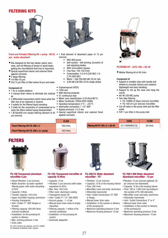
FG-100 Transparent aluminium microfilter 5 µm• Diesel Filtration: 5 μm (micron)• Water decanter: by water repellent
filtering paper, with water decanting of 93%
• Capacity: 2 litres• Transfer capacity: 105 l/min• Upper microfilter housing: aluminium• Housing: transparent• Inlet / Outlet: F1” BSP flanges or
threads• Filtering capacity: 500.000 litres
(normal conditions)• Installation: On the pumping kit
suction or delivery• Max. working pressure: 5 bar• Drain valveFG-100 G Version for gasoline, and FG-100BIO for Biodiesel availables under request.
FG-150: Transparent microfilter of capacity 10 litres• Capacity: 10 lts• Filtration: 5 μm (micron) (with water
separation to 93%)• Max. flow: 160 l/min• Filter cover: aluminium casting• Transparent vessel: PA• Inlet / Outlet: F1 1/2” GAS (BSP)• Vacuum gauge: -1 +3 bar• Manual lower drain valve to empty
impurities• Filtering capacity: 1 million of lts
(normal conditions)• Installation: on the pumping kit
suction• Automatic degasifier
FG-300/15: Water absorbent microfilter - F2”• Filtration: 15 μm (micron)• Capacity: 15 lts in the housing interior• Flow: 300 l/min• Microfilter cover and body: aluminium• Diferential manometer• Inlet / Outlet Connections: F2” BSP
or flange• Manual lower drain valve• Installation: in the suction or delivery
of the pumping kit• Maximum operating pressure: 6 bar• Maximum housing pressure: 10 bar
FG-700/1.000 Water absorbent Aluminium microfilter - 15 µm• Filtration: 15 μm (micron) (optional: 50 μm (micron) non-absorbent)
• Capacity: 15 lts in the housing interior• Flow: 700 or 1.000 l/min (according to
the number of FG-300 elements)• Microfilter cover and body: aluminium• Diferential manometer• Inlet / Outlet Connections: 3” or 4”• Manual lower drain valve• Installation: in the suction or delivery
of the pumping kit• Maximum operating pressure: 6 bar• Maximum housing pressure: 10 bar
FILTERS
Fixed and Portable Filtering Kit + pump · 50/15 µm · water absorbent
• Kits designed for the fuel (diesel, petrol, kero-sene, and oil) filtering of buried or aerial tanks, getting the microfiltered fluid free of impurities.
• Special superficial interior and external finish against corrosion
• 2 stage filtering:• 1st filter 50 μm.• 2nd 15 μm filter, to filter below 50 μm and water.
Composed of:• 1 fix or mobile platform• 2 manual drain valves to eliminate the residual
air• 2 differential manometers which show when the
filter has to be replaced or cleaned• 2 outlets for the filtered liquid sampling• 2 inlets for the connection of compressed air to
clean the filters without being disassembled• 1 Ø150x458 mm impact filtering element of 50
μm (micron)
• 1 final element of absorbent paper of 15 μm (micron)
• BAG-800 pump• Self-suction - self-priming. Eccentric of
self-adjusting blades• With recirculation bypass• Free flow: 100-150 l/min• Consumption: 4,5-6 A (230 VAC) 1,8-
2,7A (400 VAC)• Motor: 1 kW 230/400 VAC 50 Hz 3ph• 0,90 kW 230 VAC 50 Hz single-phase
• Explosionproof (ATEX)• 1400 rpm• With thermal protector• S1 continuous duty• Motor zone classification: II 2G EExd IIB T3• Motor Certificate: TÜV04 ATEX 2488X• Operation temperature: 0 ºC - +50 ºC• Inlet/outlet connection: 1 1/2" BSP• Bypass pressure: 3-3,5 bar• Special superficial interior and external finish
against corrosion.
FILTERING KITS
FLOW
Fixed Filtering Kit FG-300 x 2 100 l/min.
Fixed Filtering Kit FG-300 x 2+ pump 150 l/min.
CODE FLOW
Filtering Kit FG-100 x 2 + AG-46 01110000902152 50 l/min.
• Mobile filtering kit of 40 l/min.
Composed of:• Support in metallic tube with handle and
wheels to circulate indoors and outdoors (lighweight and easy handling)
• Support to roll up the nose and hang the nozzle
• AG-46 230 VAC pump• Two-step filtering:
• FG-100BIO of 25μm (micron) microfilter• FG-100 of 5 μm (micron) microfilter
• Cut-off valve in the pump inlet and the filter outlet
• FUP-1 pre-filter in the pump inlet
FILTERING KIT · 2xFG-100 + AG-46
28
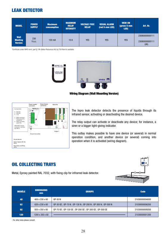
The Inpro leak detector detects the presence of liquids through its infrared sensor, activating or deactivating the desired device.
The relay output can activate or deactivate any device; for instance, a siren or a bigger light-giving indicator.
This outlay makes possible to have one device (or several) in normal operation condition, and another device (or several) coming into operation when it is activated (wiring diagram).
*Certificate under WHG norm, part § 19h (Water Resources Act) by TUV-Nord is available.
LEAK DETECTOR
MODEL POWER SUPPLY
Maximum consumption
MAXIMUM RELAY
INTENSITY
VOLTAGE FREE RELAY
VISUAL ALARM(red 5-mm LED)
VIEW ON(green 5-mm
LED)Art. Nr.
Wall MontingVersion
230 V a.c.
120 mA 10 A YES YES YES
23080000000111
23080000000111 (UK)
Wiring Diagram (Wall Mounting Version)
GREEN RED
IPD
-003
0
LEA
KM
OD
ULE
JP1
IPD
-003
4-C
R
+
BUZZER
GR
OU
ND
GR
OU
ND
NC
NC
CO
MN
ON
C
55
43
12
INPRO S.L.IPD - 0000 - E
LEA
KM
OD
ULE
IPD
-003
0
Probe 1
Probe 2 (optional)
Power supplyconnector
Relay Output connector
Serial Nr.
Ground connection
Connections:
5 – Neutral5 – Neutral4 – Live
3 – Relay common1 – Relay normally closed NC2 – Relay normally open NO.
GROUND: Faston connector terminal size M3,5.
Visuals Alarms:
Green: System OK. No Alarm
Red: Alarm and Relay active
OIL COLLECTING TRAYS
- For other sizes please consult.
Metal, Eproxy painted RAL 7032, with fixing clip for infrarred leak detector.
MODÈLE DIMENSIONS mm GROUPS Code
40 400 x 230 x 60 GP-30 N 21030000004000
62 620 x 230 x 60 GP-30 GE ; GP-70 N ; GP-130 N ; GP-200 N ; GP-300 N ; GP-500 N 21030000006200
92 920 x 350 x 60 GP-70 GE ; GP-130 GE ; GP-200 GE ; GP-300 GE ; GP-500 GE 21030000009200
120 1200 x 350 x 60 21030000001200
28 29
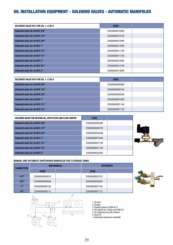
OIL INSTALLATION EQUIPMENT - SOLENOID VALVES - AUTOMATIC MANIFOLDS
SOLENOID VALVE N/C FOR OIL 1 x 230 V CODE
Solenoid valve for oil N/C 3/8” 23030000010389
Solenoid valve for oil N/C 1/2” 23030000010129
Solenoid valve for oil N/C 3/4” 23030000010349
Solenoid valve for oil N/C 1” 23030000011009
Solenoid valve for oil N/C 1¼” 23030000011149
Solenoid valve for oil N/C 1½” 23030000011129
Solenoid valve for oil N/C 2” 23030000012009
Solenoid valve for oil N/C 2½” 23030000012129
Solenoid valve for oil N/C 3” 23030000013009
SOLENOID VALVE N/O FOR OIL 1 x 230 V CODE
Solenoid valve for oil N/O 3/8” 23030000000389
Solenoid valve for oil N/O 1/2” 23030000000129
Solenoid valve for oil N/O 3/4” 23030000000349
Solenoid valve for oil N/O 1” 23030000001009
Solenoid valve for oil N/O 1¼” 23030000001149
Solenoid valve for oil N/O 1½” 23030000001129
SOLENOID VALVE FOR HEATING OIL, WITH FILTER AND FLOW LIMITER CODE
Solenoid valve for oil N/C 3/8” 23030000050389
Solenoid valve for oil N/C 1/2” 23030000050129
Solenoid valve for oil N/C 3/4” 23030000050349
Solenoid valve for oil N/C 1” 23030000051009
Solenoid valve for oil N/C 1¼” 23030000051149
Solenoid valve for oil N/C 1½” 23030000051129
Solenoid valve for oil N/C 2” 23030000052009
CONNECTIONMECHANICAL AUTOMATIC
CODE CODE
1/2” 2101000000403221000000004032
3/4” 4303000000403243000000004032
1” 0011000000403200100000004032
1½” 2111000000403221100000004032
MANUAL AND AUTOMATIC SWITCHOVER MANIFOLDS FOR 2 STORAGE TANKS
1. Oil tank2. Suction3. Flexible probe for EDM-40 2”4. Fill cabinet for 2 tanks and EDM-405. Oil collecting tray with infrared6. Inpro GP7. Automatic switchover manifolds
30
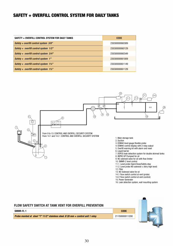
SAFETY + OVERFILL CONTROL SYSTEM FOR DAILY TANKS
SAFETY + OVERFILL CONTROL SYSTEM FOR DAILY TANKS CODE
Safety + overfill control system 3/8” 23030000060389
Safety + overfill control system 1/2” 23030000060129
Safety + overfill control system 3/4” 23030000060349
Safety + overfill control system 1” 23030000061009
Safety + overfill control system 1¼” 23030000061149
Safety + overfill control system 1½” 23030000061129
G.E.
1
2
4
59
1213
11.1 11.2
10
15
63
8
14.1 14.2
16
7
FLOW SAFETY SWITCH AT TANK VENT FOR OVERFILL PREVENTION
SMMR-FL 1 CODE
Probe monted at steel “T” 11/2” stainless steel. Ø 28 mm + control unit 1 relay 21150000011200
1. Main storage tank2. Suction3. EDM40 level gauge flexible probe4. EDM40 control display with 2 relay output5. Overfill warning kit with alarm and reset6. Liquid barrier7. DDP25 leak detection system for double skinned tanks8. INPRO GP Pumpset for oil9. NC solenoid valve for oil with flow limiter10. SMMR-2 level control11.1. Level probe Open/Close/Safety stop11.2. Level probe NO solenoid v. (Very high level)12. Filter13. NO Solenoid valve for oil14.1 Flow switch control at vent (probe)14.2 Flow switch control at vent (control)15. Power Generator16. Leak detection system, wall mounting system
From 9 to 13: CONTROL AND OVERFILL SECURITY SYSTEMFrom 14.1 and 14.2 : CONTROL AND OVERFILL SECURITY SYSTEM
30 31
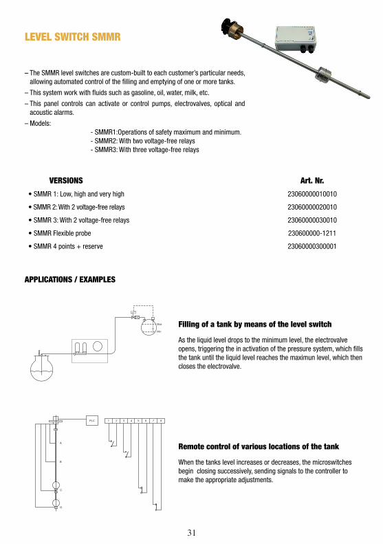
– The SMMR level switches are custom-built to each customer’s particular needs, allowing automated control of the filling and emptying of one or more tanks.
– This system work with fluids such as gasoline, oil, water, milk, etc.
– This panel controls can activate or control pumps, electrovalves, optical and acoustic alarms.
– Models: - SMMR1:Operations of safety maximum and minimum. - SMMR2: With two voltage-free relays - SMMR3: With three voltage-free relays
APPLICATIONS / EXAMPLES
���
���
Filling of a tank by means of the level switch
As the liquid level drops to the minimum level, the electrovalve opens, triggering the in activation of the pressure system, which fills the tank until the liquid level reaches the maximun level, which then closes the electrovalve.
�
�
�
��� � � � � � � � �
�
Remote control of various locations of the tank
When the tanks level increases or decreases, the microswitches begin closing successively, sending signals to the controller to make the appropriate adjustments.
VERSIONS Art. Nr.
• SMMR 1: Low, high and very high 23060000010010
• SMMR 2: With 2 voltage-free relays 23060000020010
• SMMR 3: With 2 voltage-free relays 23060000030010
• SMMR Flexible probe 230600000-1211
• SMMR 4 points + reserve 23060000300001
LEVEL SWITCH SMMR
32
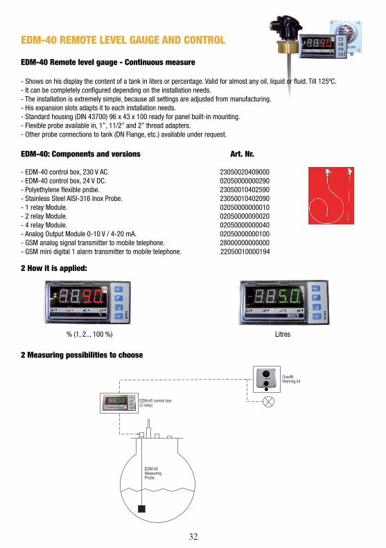
2 Measuring possibilities to choose
2 How it is applied:
% (1, 2.., 100 %) Litres
EDM-40 REMOTE LEVEL GAUGE AND CONTROL
EDM-40 Remote level gauge - Continuous measure
- Shows on his display the content of a tank in liters or percentage. Valid for almost any oil, liquid or fluid. Till 125ºC.- It can be completely configured depending on the installation needs.- The installation is extremely simple, because all settings are adjusted from manufacturing.- His expansion slots adapts it to each installation needs.- Standard housing (DIN 43700) 96 x 43 x 100 ready for panel built-in mounting.- Flexible probe available in, 1”, 11/2” and 2” thread adapters.- Other probe connections to tank (DN Flange, etc.) available under request.
EDM-40: Components and versions Art. Nr.
- EDM-40 control box, 230 V AC. 23050020409000- EDM-40 control box, 24 V DC. 02050000000290- Polyethylene flexible probe. 23050010402590- Stainless Steel AISI-316 Inox Probe. 23050010402090- 1 relay Module. 02050000000010- 2 relay Module. 02050000000020- 4 relay Module. 02050000000040- Analog Output Module 0-10 V / 4-20 mA. 02050000000100- GSM analog signal transmitter to mobile telephone. 28000000000000- GSM mini digital 1 alarm transmitter to mobile telephone. 22050010000194
32 33
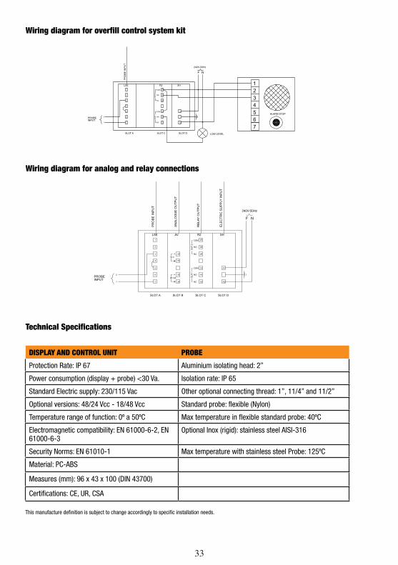
Wiring diagram for overfill control system kit
Wiring diagram for analog and relay connections
Technical Specifications
DISPLAY AND CONTROL UNIT PROBE
Protection Rate: IP 67 Aluminium isolating head: 2”
Power consumption (display + probe) <30 Va. Isolation rate: IP 65
Standard Electric supply: 230/115 Vac Other optional connecting thread: 1”, 11/4” and 11/2”
Optional versions: 48/24 Vcc - 18/48 Vcc Standard probe: flexible (Nylon)
Temperature range of function: 0º a 50ºC Max temperature in flexible standard probe: 40ºC
Electromagnetic compatibility: EN 61000-6-2, EN 61000-6-3
Optional Inox (rigid): stainless steel AISI-316
Security Norms: EN 61010-1 Max temperature with stainless steel Probe: 125ºC
Material: PC-ABS
Measures (mm): 96 x 43 x 100 (DIN 43700)
Certifications: CE, UR, CSA
This manufacture definition is subject to change accordingly to specific installation needs.
34
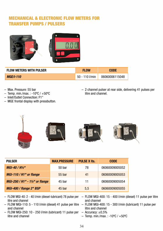
FLOW METERS WITH PULSER FLOW CODE
MGE/i-110 50 - 110 l/min 06060006115048
– Max. Pressure: 55 bar – Temp. min./max. : -10ºC / +50ºC – Inlet/Outlet Connection: F1" – MGE frontal display with pressbutton.
– 2 channel pulser at rear side, delivering 41 pulses per litre and channel.
PULSER MAX.PRESSURE PULSE X lts. CODE
MGI-40 / H½" 50 bar 78 06060009005052
MGI-110 / H1" or flange 55 bar 41 06060009005053
MGI-250 / H1" - 1½" or flange 45 bar 11 06060009005054
MGI-400 / flange 2" BSP 45 bar 5,5 06060009005055
– FLOW MGI-40: 2 - 40 l/min (diesel-lubricant) 78 pulse per litre and channel
– FLOW MGI-110: 5 - 110 l/min (diesel) 41 pulse per litre and channel
– FLOW MGI-250: 10 - 250 l/min (lubricant) 11 pulse per litre and channel
– FLOW MGI-400: 15 - 400 l/min (diesel) 11 pulse per litre and channel
– FLOW MGI-400: 15 - 300 l/min (lubricant) 11 pulse per litre and channel
– Accuracy: ±0,5% – Temp. min./max. : -10ºC / +50ºC
MECHANICAL & ELECTRONIC FLOW METERS FOR TRANSFER PUMPS / PULSERS
34 35
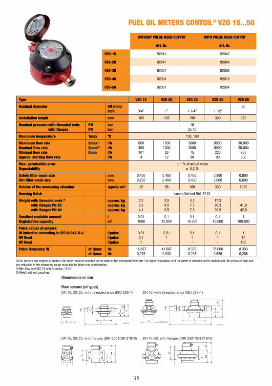
FUEL OIL METERS CONTOIL® VZO 15...50
WITHOUT PULSE REED OUTPUT WITH PULSE REED OUTPUT
Art. Nr. Art. Nr.
VZO-15 92041 92042
VZO-20 92047 92048
VZO-25 92057 92058
VZO-40 92004 92018
VZO-50 92007 92024
Type VZO 15 VZO 20 VZO 25 VZO 40 VZO 50
Nominal diameter DN (mm)inch 3/4” 1” 1 1/4” 1 1/2”
50
Installation length mm 165 165 190 300 350
Nominal pressure with threaded ends with flanges
PNPN
barbar
1625,40
Maximum temperature Tmax ºC 130, 180
Maximum flow rateNominal flow rateMinimal flow rateApprox. starting flow rate
Qmax1)
Qnom1)
Qmin
l/hl/hl/hl/h
600400104)
4
150010003012
300020007530
9000600022590
30.00020.000
750300
Max. permissible errorRepeatability
± 1 % of actual value± 0,2 %
Safety filter mesh size Dirt filter mesh size
mmmm
0,4000,250
0,4000,400
0,4000,400
0,8000,600
0,8000,600
Volume of the measuring chamber approx. cm3 12 36 100 330 1200
Housing finish enamelled red RAL 3013
Weight with threaded ends 2)
with flanges PN 25 with flanges PN 40
approx. kgapprox. kgapprox. kg
2,23,84,4
2,54,55,5
4,27,57,8
17,320,320,5
-41,042,0
Smallest readable amountRegistration capacity
lm3
0,011000
0,110.000
0,110.000
0,110.000
1100.000
Pulse values of pulsers:IN inductive according to IEC 60947-5-6RV ReedRV Reed
l/pulsel/pulsel/pulse
0,010,11
0,011-
0,11-
0,11-
110
100
Pulse frequency IN at Qmaxat Qmax
HzHz
16.6670,278
41.6670,833
8.3330,208
25.0000,625
8.3330,208
3) For burners and engines or motors, the meter must be selected on the basis of the permanent flow rate. For higher viscosities, or if the meter is installed on the suction side, the pressure drop and any reduction in the measuring range must also be taken into consideration.4) Min. flow rate VZO 15 with IN-pulser: 15 l/h5) Weight without couplings.
Dimensions in mm
Flow sensors (all types)DN 15, 20, 25: with threaded ends (ISO 228-1) DN 40: with threaded ends (ISO 228-1)
DN 15, 20, 25: with flanges (DIN 2501/SN 21843) DN 40, 50: with flanges (DIN 2501/SN 21843)
h1h2
B L
ØF
b h1h2
H
66212B AM066160.4B
36
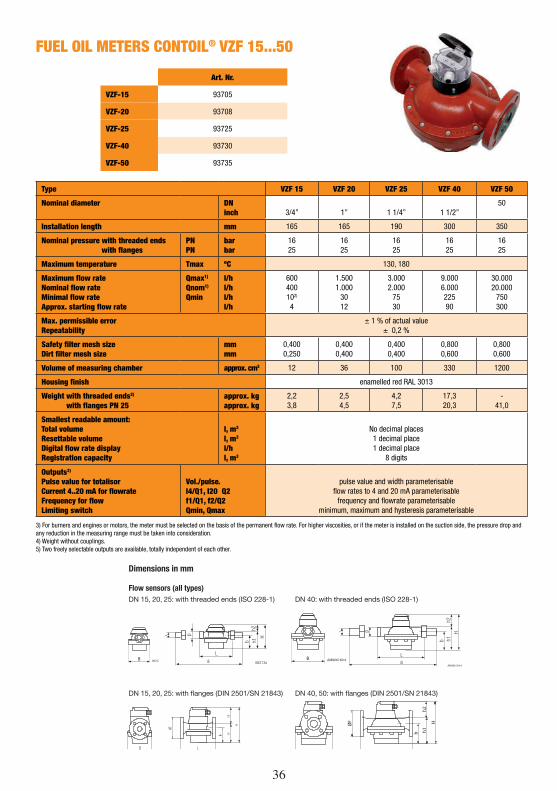
FUEL OIL METERS CONTOIL® VZF 15...50
Art. Nr.
VZF-15 93705
VZF-20 93708
VZF-25 93725
VZF-40 93730
VZF-50 93735
Type VZF 15 VZF 20 VZF 25 VZF 40 VZF 50
Nominal diameter DNinch 3/4” 1” 1 1/4” 1 1/2”
50
Installation length mm 165 165 190 300 350
Nominal pressure with threaded ends with flanges
PNPN
barbar
1625
1625
1625
1625
1625
Maximum temperature Tmax ºC 130, 180
Maximum flow rateNominal flow rateMinimal flow rateApprox. starting flow rate
Qmax1)
Qnom1)
Qmin
l/hl/hl/hl/h
600400102)
4
1.5001.000
3012
3.0002.000
7530
9.0006.00022590
30.00020.000
750300
Max. permissible errorRepeatability
± 1 % of actual value± 0,2 %
Safety filter mesh sizeDirt filter mesh size
mmmm
0,4000,250
0,4000,400
0,4000,400
0,8000,600
0,8000,600
Volume of measuring chamber approx. cm3 12 36 100 330 1200
Housing finish enamelled red RAL 3013
Weight with threaded ends2)
with flanges PN 25approx. kgapprox. kg
2,23,8
2,54,5
4,27,5
17,320,3
-41,0
Smallest readable amount:Total volumeResettable volumeDigital flow rate displayRegistration capacity
l, m3
l, m3
l/hl, m3
No decimal places1 decimal place 1 decimal place
8 digits
Outputs3)
Pulse value for totalisorCurrent 4..20 mA for flowrateFrequency for flowLimiting switch
Vol./pulse.l4/Q1, I20 Q2f1/Q1, f2/Q2Qmin, Qmax
pulse value and width parameterisableflow rates to 4 and 20 mA parameterisable
frequency and flowrate parameterisableminimum, maximum and hysteresis parameterisable
3) For burners and engines or motors, the meter must be selected on the basis of the permanent flow rate. For higher viscosities, or if the meter is installed on the suction side, the pressure drop and any reduction in the measuring range must be taken into consideration.4) Weight without couplings.5) Two freely selectable outputs are available, totally independent of each other.
Dimensions in mm
Flow sensors (all types)DN 15, 20, 25: with threaded ends (ISO 228-1) DN 40: with threaded ends (ISO 228-1)
DN 15, 20, 25: with flanges (DIN 2501/SN 21843) DN 40, 50: with flanges (DIN 2501/SN 21843)
h1h2
B L
ØF
b h1h2
H
66212B AM066160.4B
36 37
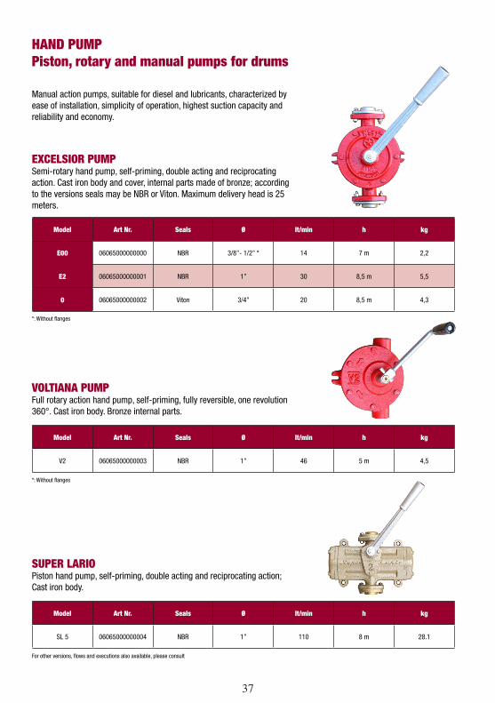
HAND PUMPPiston, rotary and manual pumps for drums
EXCELSIOR PUMP Semi-rotary hand pump, self-priming, double acting and reciprocating action. Cast iron body and cover, internal parts made of bronze; according to the versions seals may be NBR or Viton. Maximum delivery head is 25 meters.
VOLTIANA PUMPFull rotary action hand pump, self-priming, fully reversible, one revolution 360°. Cast iron body. Bronze internal parts.
SUPER LARIOPiston hand pump, self-priming, double acting and reciprocating action; Cast iron body.
Manual action pumps, suitable for diesel and lubricants, characterized by ease of installation, simplicity of operation, highest suction capacity and reliability and economy.
*: Without flanges
*: Without flanges
For other versions, flows and executions also available, please consult
Model Art Nr. Seals Ø lt/min h kg
E00 06065000000000 NBR 3/8”- 1/2” * 14 7 m 2,2
E2 06065000000001 NBR 1” 30 8,5 m 5,5
0 06065000000002 Viton 3/4” 20 8,5 m 4,3
Model Art Nr. Seals Ø lt/min h kg
V2 06065000000003 NBR 1” 46 5 m 4,5
Model Art Nr. Seals Ø lt/min h kg
SL 5 06065000000004 NBR 1” 110 8 m 28.1
38
Dear Customer,
Please fill and send us the next questionnaire, very helpful in the selection for the best oil transferring solution for your installation. Please add also a sketch if possible.
Is this System: For a new installation Yes / No Renovation of an existing installation Yes / No
Tank Type Pcs. Litre Ø or height
TANK INSTALLATION
- Underground tank
- One free standing and/or lying tank
POWER GENERATOR
Total genset / appliances nr Pcs. max kg/h
Total genset power output kVA
All the gensets in the same room? Yes / No
PIPING
Piping from the tank to the appliance Height m
Length m
Piping - if existing – Inside Diameter mm
Piping under ground (not observable) Yes / No
Piping visible Yes / No
Piping partially not visible Yes / No
Piping with frequent up & down gradients Yes / No
POWER SUPPLY Three Phase
Single Phase
Pump system type (your advice)? � Single pump.................................................................Models: N � Duplex Pump with automatic switch over......................... Models: GE, ZW System: � Pressure accumulating system, without cable to level probe....Model: GP � Main tank to daily service tank transfer............................Models: FP, ATAM Medium: If medium is not standard diesel, please detail or join medium datasheet. Other: ……………………………………………………………………………………………………………………………………………………….
Need catalogue? Yes / No. Bid text needed? Yes / No. Date: Sender:
LENGTH OF THE PIPE RUN
Suction side Suction lift Tank bottom-Pump m
Suction length Tank bottom-Pump m
Drive side Pressure lift Pump-Burner m
Pressure length Pump-Burner m
COMMUNICATION
Mod-bus � LAN/ethernet � Other:…………………………………………………………
Digital I / O Yes / No Nr. I:……………… Nr. O:………………
Analog I / O Yes / No Nr. I:……………… Nr. O:………………
GSM Yes / No
SIGNALS Flow meter Nr. :………………
REDUNDANCY
Standard �
TIER III �
TIER IV �
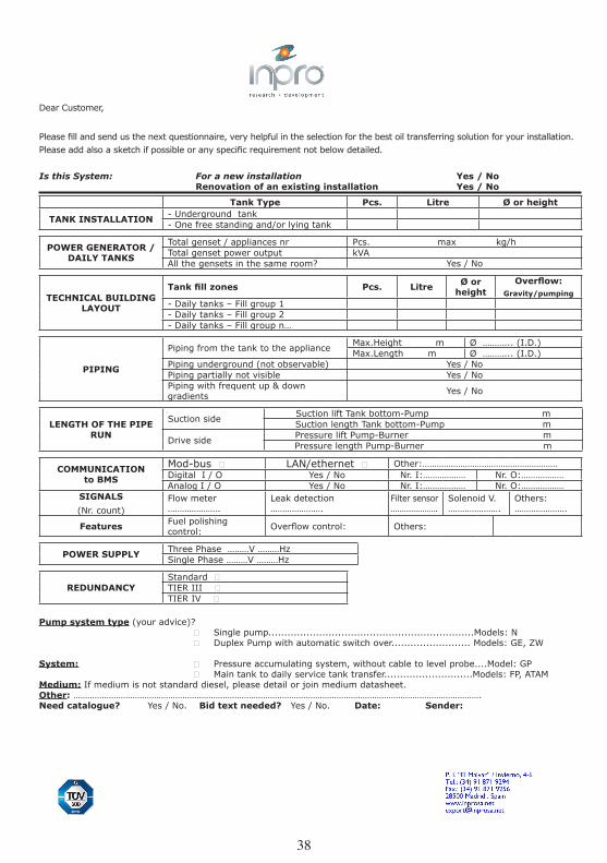
Dear Customer,
Please fill and send us the next questionnaire, very helpful in the selection for the best oil transferring solution for your installation. Please add also a sketch if possible or any specific requirement not below detailed.
Is this System: For a new installation Yes / No Renovation of an existing installation Yes / No
Tank Type Pcs. Litre Ø or height
TANK INSTALLATION - Underground tank- One free standing and/or lying tank
POWER GENERATOR / DAILY TANKS
Total genset / appliances nr Pcs. max kg/hTotal genset power output kVA All the gensets in the same room? Yes / No
TECHNICAL BUILDING LAYOUT
Tank fill zones Pcs. Litre Ø or height
Overflow:Gravity/pumping
- Daily tanks – Fill group 1- Daily tanks – Fill group 2- Daily tanks – Fill group n…
PIPING
Piping from the tank to the appliance Max.Height m Ø ………... (I.D.)Max.Length m Ø ………... (I.D.)
Piping underground (not observable) Yes / NoPiping partially not visible Yes / NoPiping with frequent up & down gradients Yes / No
LENGTH OF THE PIPE RUN
Suction side Suction lift Tank bottom-Pump mSuction length Tank bottom-Pump m
Drive side Pressure lift Pump-Burner mPressure length Pump-Burner m
COMMUNICATIONto BMS
Mod-bus � LAN/ethernet � Other:…………………………………………………Digital I / O Yes / No Nr. I:……………… Nr. O:………………Analog I / O Yes / No Nr. I:……………… Nr. O:………………
SIGNALS(Nr. count)
Flow meter ………………….
Leak detection ………………….
Filter sensor ………………….
Solenoid V. ………………….
Others: ………………….
Features Fuel polishing control: Overflow control: Others:
POWER SUPPLY Three Phase ………V ………Hz Single Phase ………V ………Hz
REDUNDANCYStandard �TIER III �TIER IV �
Pump system type (your advice)? � Single pump.................................................................Models: N � Duplex Pump with automatic switch over......................... Models: GE, ZW
System: � Pressure accumulating system, without cable to level probe....Model: GP � Main tank to daily service tank transfer............................Models: FP, ATAMMedium: If medium is not standard diesel, please detail or join medium datasheet.Other: ……………………………………………………………………………………………………………………………………………………….Need catalogue? Yes / No. Bid text needed? Yes / No. Date: Sender:

38
INPRO GROUPwww.inprogroup.net
Your trading partner: