
Innovative Way for Lay-up of Conical Shaped Sandwich ... aircraft, Unmanned Aerial Vehicle s and...
7
Abstract—A new lay-up process has been invented, which involves a layer being made from three special shape prepreg. The first piece is butterfly shaped and remaining two pieces shaped trapezoid, with radius on smaller edge. Joining of all three pieces is butt-joint type. The subsequent layers are also in pieces of similar shapes with varying sizes. The lay-up of subsequent layers is carried out at an angle of rotation with respect to adjacent layer in clockwise direction. The component manufactured has no flaws and defects. This lay-up process reduces the wastage of raw material and also reduces the manufacturing cycle time. Index Terms—Composite, lay-up, manufacturing, prepreg, interlaminar, flat wise tensile strength. I. INTRODUCTION Composite materials have emerged as the material of choice for reducing weight, cost and increasing the performance of military aircraft, general aviation aircraft, transport aircraft, Unmanned Aerial Vehicles and space launch vehicles. Major advancements have been made in design, fabrication and analysis of large complex aerospace structure. The use of composites can achieve weight reduction varying from 10% to 50% along with a cost reduction of 10% to 20% with equal performance when compared with components made of conventional metallic material [1]. A reduction of 1 Kg mass leads to the reduction of fuel consumption of around 120 litres per year [1]. Composite material based applications have grown rapidly in the aircraft industry. The percentage of structural weight made from composite materials has grown from less than 1% to more than 50% over the past four decades [2]. Complex products involving many different types of parts produced in small lots/sub-assemblies are required in the aircraft industry. Hence, various molds, dies, tools and jigs-fixtures are required for manufacturing of relatively small number of sheet metal and composite parts. Composite parts and co-cured assemblies are unique as plies are placed one above the other to build a laminate. The placement of plies allows for structure to be precisely tailored, but have the possibility of individual plies being distorted within a laminate. In many cases these ply distortions may not be visible after the cure process. This makes the manufacturing development process very important. Internal fabrication anomalies must be Manuscript received July 15, 2014; revised December 22, 2104. This work was supported by Hindustan Aeronautics Limited, Transport Aircraft Division, Kanpur, India. Farendra Singh Chouhan is with Hindustan Aeronautics Limited, Transport Aircraft Division, Kanpur, India (e-mai: [email protected]). understood and well-characterized, to account for the design and analysis of the structure. The collection of laminated layers shaped onto the mold before curing is called a lay-up. Desired mechanical properties in composites are achieved by defined stacking sequence/lay-up. In a typical lay-up, the angular orientation of fibres in each layer/lamina is specified. The conventional method of lay-up to manufacture any composite part is to place all layers one by one (in single piece) at different angles to achieve the required thickness and strength. II. METHODOLOGY The dimensions of conical composite part are critical as per manufacturing point of view. The corner base radius is R", outer radius R', thickness T, Draft angle Ø and maximum outer diameter of component is D (see Fig. 1). Following criticalities emerge from manufacturing point of view: R" + T > R' , (In present case, outer radius ≈ inner radius ≈ thickness) Wrinkles at the sharp corner radius Lay-up process Uniform thickness throughout the surface Fig. 1. Schematic view of component. Therefore, conventional lay-up process is not feasible for conical shaped components with sharp corner radius because wrinkles appear at the sharp corner joints. Hence a need is felt to invent a non-conventional lay-up process to overcome such problems. Binding/splicing of hex core aramid honeycomb and ox-core aramid honeycomb is done through foaming core filler (see Fig. 2). A. Material Used All prepreg and aramid honeycomb raw materialsweresourced from M/s Hexcel, France “unpublished” [3], “unpublished” [4]. The chemical, physical Innovative Way for Lay-up of Conical Shaped Sandwich Composite Component with Sharp Corner Radius Farendra Singh Chouhan International Journal of Materials, Mechanics and Manufacturing, Vol. 3, No. 2, May 2015 110 DOI: 10.7763/IJMMM.2015.V3.177
Transcript of Innovative Way for Lay-up of Conical Shaped Sandwich ... aircraft, Unmanned Aerial Vehicle s and...

Abstract—A new lay-up process has been invented, which
involves a layer being made from three special shape prepreg.
The first piece is butterfly shaped and remaining two pieces
shaped trapezoid, with radius on smaller edge. Joining of all
three pieces is butt-joint type. The subsequent layers are also in
pieces of similar shapes with varying sizes. The lay-up of
subsequent layers is carried out at an angle of rotation with
respect to adjacent layer in clockwise direction. The component
manufactured has no flaws and defects. This lay-up process
reduces the wastage of raw material and also reduces the
manufacturing cycle time.
Index Terms—Composite, lay-up, manufacturing, prepreg,
interlaminar, flat wise tensile strength.
I. INTRODUCTION
Composite materials have emerged as the material of
choice for reducing weight, cost and increasing the
performance of military aircraft, general aviation aircraft,
transport aircraft, Unmanned Aerial Vehicles and space
launch vehicles. Major advancements have been made in
design, fabrication and analysis of large complex aerospace
structure. The use of composites can achieve weight
reduction varying from 10% to 50% along with a cost
reduction of 10% to 20% with equal performance when
compared with components made of conventional metallic
material [1]. A reduction of 1 Kg mass leads to the reduction
of fuel consumption of around 120 litres per year [1].
Composite material based applications have grown rapidly in
the aircraft industry. The percentage of structural weight
made from composite materials has grown from less than 1%
to more than 50% over the past four decades [2]. Complex
products involving many different types of parts produced in
small lots/sub-assemblies are required in the aircraft industry.
Hence, various molds, dies, tools and jigs-fixtures are
required for manufacturing of relatively small number of
sheet metal and composite parts. Composite parts and
co-cured assemblies are unique as plies are placed one above
the other to build a laminate. The placement of plies allows
for structure to be precisely tailored, but have the possibility
of individual plies being distorted within a laminate. In many
cases these ply distortions may not be visible after the cure
process. This makes the manufacturing development process
very important. Internal fabrication anomalies must be
Manuscript received July 15, 2014; revised December 22, 2104. This
work was supported by Hindustan Aeronautics Limited, Transport Aircraft
Division, Kanpur, India.
Farendra Singh Chouhan is with Hindustan Aeronautics Limited,
Transport Aircraft Division, Kanpur, India (e-mai:
understood and well-characterized, to account for the design
and analysis of the structure. The collection of laminated
layers shaped onto the mold before curing is called a lay-up.
Desired mechanical properties in composites are achieved by
defined stacking sequence/lay-up. In a typical lay-up, the
angular orientation of fibres in each layer/lamina is specified.
The conventional method of lay-up to manufacture any
composite part is to place all layers one by one (in single
piece) at different angles to achieve the required thickness
and strength.
II. METHODOLOGY
The dimensions of conical composite part are critical as
per manufacturing point of view. The corner base radius is R",
outer radius R', thickness T, Draft angle Ø and maximum
outer diameter of component is D (see Fig. 1). Following
criticalities emerge from manufacturing point of view:
R" + T > R' , (In present case, outer radius ≈ inner radius
≈ thickness)
Wrinkles at the sharp corner radius
Lay-up process
Uniform thickness throughout the surface
Fig. 1. Schematic view of component.
Therefore, conventional lay-up process is not feasible for
conical shaped components with sharp corner radius because
wrinkles appear at the sharp corner joints. Hence a need is felt
to invent a non-conventional lay-up process to overcome such
problems. Binding/splicing of hex core aramid honeycomb
and ox-core aramid honeycomb is done through foaming core
filler (see Fig. 2).
A. Material Used
All prepreg and aramid honeycomb raw
materialsweresourced from M/s Hexcel, France
“unpublished” [3], “unpublished” [4]. The chemical, physical
Innovative Way for Lay-up of Conical Shaped Sandwich
Composite Component with Sharp Corner Radius
Farendra Singh Chouhan
International Journal of Materials, Mechanics and Manufacturing, Vol. 3, No. 2, May 2015
110DOI: 10.7763/IJMMM.2015.V3.177

and mechanical property of aramid honeycomb is available
on Hexcel website [5]. Following materialswere used to
manufacture the component and specimens:
HexWeb®HRH-10-3/16-3.0 (Hex core aramid
Honeycomb)
HexWeb®HRH-10/OX-3/16-3.0 (Ox core
aramidHoneycomb)
HexPly®913/50%/K285 (Kevlar prepreg)
HexPly®913/37%/120 (Glass prepreg)
AF-3024 (Foaming Adhesive)
EC-3500, Part A & B (Core Filler)
BJO-0930 (Micro-balloon Filler)
LY 556 (Epoxy Resin)
LN9169-8.4515.60 (Glass Cloth)
HY 951 (Hardener)
Fig. 2. Lay-up scheme.
Fig. 3. Mold and metal tool.
B. Design and Development of Manufacturing Technology
The first time development of the sharp corner radius
sandwich composite component requires skill, experience
and innovative thinking in lay-up technology and composite
manufacturing. The following manufacturing technology was,
therefore, invented to fabricate the component.
C. Mold Construction
It was requirement to make a high temperature resistance
single piece mold. A female mold was developed using
E-Glass fibre and epoxy resin with wet lay-up. It was
developed with outer radius R' at joining section of slant
periphery and circular section (see Fig. 3). Another metal tool
was developed with radius R'' + T (see Fig. 3). This metal tool
helped in achieving the radius of R'' + T.
D. Development of Lay-up
Outer radius was achieved by using core filler compound.
After that, R'' + T radius was achieved by using metal tool
(see Fig. 4).
Fig. 4. Mold with achieving outer radius by using core filler.
During lay-up, the first layer of Glass prepreg was divided
into three segments having special shapes. The first segment
shape was butterfly with center portion diameter D1, second
and third segment shape was trapezoid. The butterfly shape
segment was aligned with 0⁰ reference line. All segments
were laid-up with butt joint (see Fig. 5-Fig. 8).
Fig. 5. Layer divided into three segments.
Fig. 6. Butterfly shape segment of layer position on mold.
If a layer of lay-up could not be manufactured from one
single piece, the section of layer needed to overlap by 30tr ,
International Journal of Materials, Mechanics and Manufacturing, Vol. 3, No. 2, May 2015
111

where tr is patch thickness or 12-15 mm [6] or 15±2 mm to
25±5 mm depending upon the design requirement
“unpublished” [7], “unpublished” [8].
Fig. 7. Trapezoid shape segments of layer position on mold.
Fig. 8. Layer with butt joint.
The Second layer of Glass prepreg was also divided into
three segments having special shape. The first segment shape
was also butterfly, second and third segment shape was
trapezoid. Diameter of circular portion of butterfly shape
segment was increased by 30 mm with respect to previous
layer. Butterfly shape segment was rotated at an angle of 10º
in clockwise direction with respect to 0º reference line which
fulfilled the design requirement and eliminated overlap
requirement. All segments were laid-up with butt joint (see
Fig. 9).
Fig. 9. Layer with 10° clockwise rotation and 30 mm increase in diameter.
Further, next layer of Kevlar prepreg (third layer) was also
divided into three segments having special shape. The first
segment shape was butterfly, second and third segment shape
was trapezoid. The diameter of circular portion of butterfly
shape segment was further increased by 30 mm with respect
to the previous layer. Butterfly shape segment was rotated at
an angle of 10° in clockwise direction with respect to adjacent
layer which meant 20° rotations in clockwise direction with
respect to 0° reference lines which fulfilled the design
requirement and eliminated overlap requirement. All
segments were laid-up with butt joint (see Fig. 10).
Fig. 10. Layer with 20° clockwise rotation and 60mm increase in diameter.
The further next layer of Kevlar prepreg (fourth layer) was
also divided into three segments having special shape. The
first segment shape was butterfly, second and third segments
shape was trapezoid. The diameter of circular portion of
butterfly shape segment was further increased with 30 mm
with respect to previous layer. Butterfly shape segment was
rotated at an angle of 10º clockwise with respect to adjacent
layer, which meant 30º with respect to 0º reference line and
which fulfilled the design requirement and eliminated overlap
requirement. All segments were laid-up with butt joint (see
Fig. 11).
Fig. 11. Layer with 30° clockwise rotation and 90 mm increase in diameter.
Fig. 12. Finished component.
The further next layer of Kevlar prepreg (fifth layer) was
also divided into three segments having special shape. The
first segment shape was butterfly, second and third segment
shape was trapezoid. The diameter of circular portion of
butterfly shape segment was reduced to diameter D1 which
was equal to first layer diameter of Kevlar prepreg. But the
International Journal of Materials, Mechanics and Manufacturing, Vol. 3, No. 2, May 2015
112
rotation with respect to adjacent layer continued at an angle
of 10º.
The whole process was repeated for all subsequent layers
alternatively after every four layers. Vacuum bagging was
carried out after every two layers to obtain a better surface
finish and quality of the product. The sandwich component
was made successfully to meet design requirement (see Fig.
12).
III. CURING CYCLE
Fig. 13. Curing cycle.
IV. INSPECTION
Following inspection was carried out on the finished
component without surface protection:
1) External defects
The component was inspected for cracks, cut fibres,
bubbles, resin rich area, resin starved area, process brake, pits
and humps & de-lamination as per MIL Standard [10].
2) X-ray test
X-ray test were carried out as per MIL Standard [10].
V. DESTRUCTIVE TESTING
Following destructive tests have been carried out at coupon
level:
A. Flat Wise Tensile Test
1) Manufacturing of test specimen
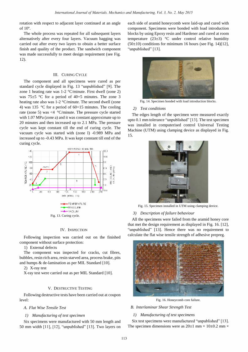
Six specimens were manufactured with 50 mm length and
50 mm width [11], [12], “unpublished” [13]. Two layers on
each side of aramid honeycomb were laid-up and cured with
component. Specimens were bonded with load introduction
blocks by using Epoxy resin and Hardener and cured at room
temperature (23±3) °C under control relative humidity
(50±10) conditions for minimum 16 hours (see Fig. 14)[12],
“unpublished” [13].
Fig. 14. Specimen bonded with load introduction blocks.
2) Test conditions
The edges length of the specimen were measured exactly
upto 0.1 mm tolerance “unpublished” [13]. The test specimen
was installed in computerised control Universal Testing
Machine (UTM) using clamping device as displayed in Fig.
15.
Fig. 15. Specimen installed in UTM using clamping device.
3) Description of failure behaviour
All the specimens were failed from the aramid honey core
that met the design requirement as displayed in Fig. 16. [12],
“unpublished” [13]. Hence there was no requirement to
calculate the flat wise tensile strength of adhesive prepreg.
Fig. 16. Honeycomb core failure.
B. Interlaminar Shear Strength Test
1) Manufacturing of test specimens
Six test specimens were manufactured “unpublished” [13].
The specimen dimensions were as 20±1 mm × 10±0.2 mm ×
International Journal of Materials, Mechanics and Manufacturing, Vol. 3, No. 2, May 2015
113
The component and all specimens were cured as per
standard cycle displayed in Fig. 13 “unpublished” [9]. The
zone 1 heating rate was 1-2 °C/minute. First dwell (zone 2)
was 75±5 °C for a period of 40+5 minutes. The zone 3
heating rate also was 1-2 °C/minute. The second dwell (zone
4) was 135 °C for a period of 60+15 minutes. The cooling
rate (zone 5) was <4 °C/minute. The pressure cycle started
with 1.07 MPa (zone a) and it was constant approximate up to
20 minutes and then increased up to 2.1 MPa. The pressure
cycle was kept constant till the end of curing cycle. The
vacuum cycle was started with (zone I) -0.989 MPa and
increased up to -0.43 MPa. It was kept constant till end of the
curing cycle.

2±0.2 mm “unpublished” [13], “unpublished” [14]. The
manufactured specimens are displayed in Fig.17. Each
specimen was manufactured with 8 layers of Kevlar prepreg.
The stacking sequence of all specimens was[0/90/0/90]S.The
measured dimensions for all six specimens were as displayed
in Table I.
TABLEI: MEASURED DIMENSIONS OF SPECIMENS
Specimen
No.
Width of the
specimen (a) in
mm
Thickness of the
specimen(b) in mm
1 10.06 2.13
2 10.03 2.06
3 10.04 1.89
4 10.06 2.04
5 10.08 2.13
6 10.04 1.94
Fig. 17. Manufactured specimens.
2) Test conditions
All specimens were tested for a short beam bending test
device (see Fig. 18.) in the longitudinal direction of the
specimen. The machine speed was 1mm/min “unpublished”
[13], [15].
Fig. 18. Specimen installed in the UTM using clamping device.
3) Calculation of interlaminar shear strength
The Interlaminar Shear Strength was calculated in 0⁰ and
90° direction as per “(1)”, “unpublished” [13], “unpublished”
[14], [15].
𝜏𝑏𝐵00 𝑜𝑟 𝜏𝑏𝐵900 = 0.75 ∗𝐹
𝑎∗𝑏 (1)
where 𝜏𝑏𝐵0° 𝑜𝑟 𝜏𝑏𝐵90° is Interlaminar Shear Strength in 0°
and 90° directions, respectively.
𝐹= applied force till fracture in N
𝑎= width of the specimen in mm
𝑏= thickness of the specimen in mm
VI. RESULTS
The test results at coupon level and components level were
as given below:
Flat-wise Tensile Test (FTT) at coupon level. All the test
specimens failed from honeycomb core.
X-Ray Test of the components for proper core splicing
and to ensure no core damage. The X-ray of component
met all the design criteria.
Interlaminar Shear Strength (ILSS): Stress-strain
diagrams for all six specimens are displayed in Fig.
19-Fig. 24. The obtained results of six specimens are
displayed in Table II.
TABLEII: ILSS TEST RESULTS
Specimen No. Applied Force(N) ILSS (N/mm2)
1 1173.40 41.070
2 1124.70 40.825
3 1002.60 39.627
4 1114.30 40.725
5 1138.30 39.762
6 1044.90 40.234
Fig. 19. Stress-Strain diagram for specimen 1.
Fig. 20. Stress-Strain diagram for specimen 2.
Fig. 21. Stress-Strain diagram for specimen 3.
International Journal of Materials, Mechanics and Manufacturing, Vol. 3, No. 2, May 2015
114
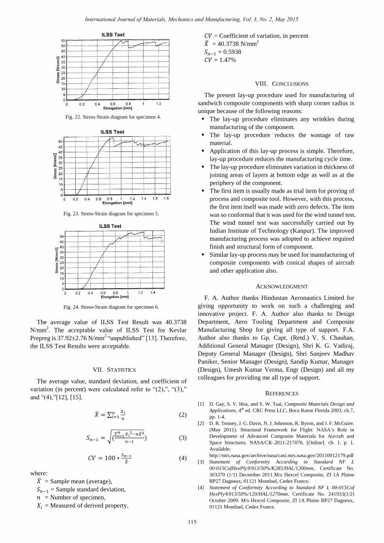
Fig. 22. Stress-Strain diagram for specimen 4.
Fig. 23. Stress-Strain diagram for specimen 5.
Fig. 24. Stress-Strain diagram for specimen 6.
The average value of ILSS Test Result was 40.3738
N/mm2. The acceptable value of ILSS Test for Kevlar
Prepreg is 37.92±2.76 N/mm2 “unpublished” [13]. Therefore,
the ILSS Test Results were acceptable.
VII. STATISTICS
The average value, standard deviation, and coefficient of
variation (in percent) were calculated refer to “(2),”, “(3),”
and “(4),”[12], [15].
�̅� = ∑𝑋𝑖
𝑛
𝑛𝑖=1 (2)
𝑆𝑛−1 = √(∑ 𝑋𝑖
2−𝑛�̅�2𝑛𝑖=1
𝑛−1) (3)
𝐶𝑉 = 100 ∗𝑆𝑛−1
�̅� (4)
where:
�̅� = Sample mean (average),
𝑆𝑛−1 = Sample standard deviation,
𝑛 = Number of specimen,
𝑋𝑖 = Measured of derived property,
𝐶𝑉 = Coefficient of variation, in percent
�̅� = 40.3738 N/mm2
𝑆𝑛−1 = 0.5938
𝐶𝑉 = 1.47%
VIII. CONCLUSIONS
The present lay-up procedure used for manufacturing of
sandwich composite components with sharp corner radius is
unique because of the following reasons:
The lay-up procedure eliminates any wrinkles during
manufacturing of the component.
The lay-up procedure reduces the wastage of raw
material.
Application of this lay-up process is simple. Therefore,
lay-up procedure reduces the manufacturing cycle time.
The lay-up procedure eliminates variation in thickness of
joining areas of layers at bottom edge as well as at the
periphery of the component.
The first item is usually made as trial item for proving of
process and composite tool. However, with this process,
the first item itself was made with zero defects. The item
was so conformal that it was used for the wind tunnel test.
The wind tunnel test was successfully carried out by
Indian Institute of Technology (Kanpur). The improved
manufacturing process was adopted to achieve required
finish and structural form of component.
Similar lay-up process may be used for manufacturing of
composite components with conical shapes of aircraft
and other application also.
ACKNOWLEDGMENT
F. A. Author thanks Hindustan Aeronautics Limited for
giving opportunity to work on such a challenging and
innovative project. F. A. Author also thanks to Design
Department, Aero Tooling Department and Composite
Manufacturing Shop for giving all type of support. F.A.
Author also thanks to Gp. Capt. (Retd.) V. S. Chauhan,
Additional General Manager (Design), Shri K. G. Vadiraj,
Deputy General Manager (Design), Shri Sanjeev Madhav
Paniker, Senior Manager (Design), Sandip Kumar, Manager
(Design), Umesh Kumar Verma, Engr (Design) and all my
colleagues for providing me all type of support.
REFERENCES
[1] D. Gay, S. V. Hoa, and S. W. Tsai, Composite Materials Design and
Applications, 4th ed. CRC Press LLC, Boca Raton Florida 2003, ch.7,
pp. 1-4.
[2] D. R. Tenney, J. G. Davis, N. J. Johnston, R. Byron, and J. F. McGuire.
(May 2011). Structural Framework for Flight: NASA’s Role in
Development of Advanced Composite Materials for Aircraft and
Space Structures. NASA/CR–2011-217076. [Online]. ch. 1. p. 1.
Available:
http://ntrs.nasa.gov/archive/nasa/casi.ntrs.nasa.gov/20110012179.pdf
[3] Statement of Conformity According to Standard NF L
00-015CofHexPly®913/50%/K285/HAL/1200mm, Certificate No.
303370 (1/1) December 2011.M/s Hexcel Composite, ZI 1A Plaine
BP27 Dagneux, 01121 Montluel, Cedex France.
[4] Statement of Conformity According to Standard NF L 00-015Cof
HexPly®913/50%/120/HAL/1270mm, Certificate No. 241933(1/2)
October 2009. M/s Hexcel Composite, ZI 1A Plaine BP27 Dagneux,
01121 Montluel, Cedex France.
International Journal of Materials, Mechanics and Manufacturing, Vol. 3, No. 2, May 2015
115

[5] Hexcel Composite. (August 2013). HexWeb®HRH-10®, Aramid
Fiber/Phenolic Resin Honeycomb, product data. [Online]. Available:
http://www.hexcel.com/Resources/Datasheets/Honeycomb-Data-Shee
ts/HRH_10_us.pdf
[6] C. Soutis and F. Z. Hu, “Design and performance of bonded patch
repairs of composite structures,” Proc Instn Mech Engrs, vol. 211, part
G, pp. 263-271, May 1997.
[7] Dornier 228 Structural Repair Manual, re.9, Hindustan Aeronautics
Limited, India, February 2007, ch. 51-72-40, p.210.
[8] Unmanned Air Vehicle (UAV) Structure Repair, re.1, Hindustan
Aeronautics Limited, India, December 2003, ch. 7, pp. 101-156
[9] Cure Cycle for Parts with Al face Sheets, Composite Face Sheets,
FM73 and Low Density Nomex Core (32 Kg/m3 and 40 Kg/m3) Glass
Reinforcements, HAL Standard SK/ALH/COMP/041, appendix 'D'.
October 1995.
[10] Adhesive Bonded Metal Faced Sandwich Structures, Acceptance
Criteria Military Specification, MIL-A-83376A (USAF) June 1978.
[11] Composite Materials Handbook, Polymer Matrix Composites
Guidelines for Characterisation of Structural Materials, vol. 1,
MIL-HDBK-17-1F, June 2002.
[12] Standard Test Method for Tensile Strength of Flat Sandwich
Constructions in Flatwise Plane, ASTM Standards, C297/C297M-04,
reapproved 2010.
[13] Design Standard for Preimpregnated Lay-ups of Fibre-Fabric (GFRP,
CFRP, and SFRP) with Epoxy Matrix of Dornier -228 Aircraft, DON
128 Part 1, February 1990.
[14] Inter Laminar Shear Strength (ILSS) or Short Beam Strength, HAL
Standard CMD/QAP (ALH)/024, August 2012.
[15] Standard Test Method for Short-Beam Strength of Polymer Matrix
Composite Materials and their Laminates, ASTM Standard
D2344/D2344M-00.
Farendra Singh Chouhan was born on May 1,
1980. His areas of experience include design and
development of repair schemes for repair of
metallic and composite aircraft structure; design
and development of aircraft structure by using
Unigraphics software; also, design and
development of repair scheme for repair of metallic
and composite unmanned aerial vehicle (UAV);
stress analysis and weight and centre of gravity
report of aircraft airframe using Nastran/Patran
software; development of supplement maintenance
manual; supplement IPC etc for DO-228 and HS-748 aircraft; obtaining
approval of structural modification for integration of different types’
sensors, upgraded system, new system and surveillance system on DO-228
and HS-748 aircraft to meet the customer requirements from Centre for
Military Airworthiness and Certification (CEMILAC) and Regional Centre
for Military Airworthiness (RCMA).
International Journal of Materials, Mechanics and Manufacturing, Vol. 3, No. 2, May 2015
116