Innovative Uses of BIM for Facility Management · PDF fileInnovative Uses of BIM for Facility...
119
Innovative Uses of BIM for Facility Management A Major Qualifying Project Submitted to the faculty of Worcester Polytechnic Institute In partial fulfillment of the requirements for the Degree of Bachelor of Science in Civil Engineering by Kristen D. Hunt Juan D. Torres Betancur Advisor: Professor Guillermo Salazar Sponsoring Agency: Massachusetts Port Authority 3/4/2015 Project ID: GFS-1603
Transcript of Innovative Uses of BIM for Facility Management · PDF fileInnovative Uses of BIM for Facility...
Innovative Uses of BIM for
Facility Management
A Major Qualifying Project Submitted to the faculty of
Worcester Polytechnic Institute
In partial fulfillment of the requirements for the
Degree of Bachelor of Science in Civil Engineering by
Kristen D. Hunt
Juan D. Torres Betancur
Advisor:
Professor Guillermo Salazar
Sponsoring Agency:
Massachusetts Port Authority
3/4/2015
Project ID: GFS-1603

ii
Abstract
The goal of this project is to contribute to the improvement of the facility management
operations for the Massachusetts Port Authority by streamlining the handover process and
optimizing asset operations. This project contributes to the gradual improvement of the facility
management functions at Massport by extending the current use of Building Information
Modeling (BIM). This project enriched the BIM models of the Framingham Parking Garage
facility and created a template to help investigate better practices for data attainment.
Information collected was incorporated into the existing BIM model to facilitate future
operations of maintenance. It also explored potential improvements for the interoperability
between BIM model and the Computer Maintenance Management System. Extensions for
improved BIM interoperability with structural analysis were also explored.
iii
Capstone Design Statement
This project used Building Information Modeling (BIM) technology to design an
improved handover process for the sponsor, the Massachusetts Port Authority (Massport). Their
four-story Logan Express Garage, in Framingham, Massachusetts was employed as the model for
the case study and structural analysis. This case study looked into the structural engineering,
construction, and facility management of this structure. The study included an investigation of
existing processes and, based on needs, modified models to represent the product of the
improved handover process. Guidelines were created for future implementation of the proposed
process.
The structural analysis was both completed through hand calculations and also through
the Robot Structural Analysis software application. The results were analyzed and compared to
one another and conclusions were drawn. The structural review was conducted according to
AISC design standards and the IBC building code, using the as-built structural models for this
facility. The BIM model, originally created using Revit software, was imported into the Robot
Structural Analysis application and adjusted so the program would perform the structural
analysis. This capstone design addressed the realistic constraints of health and safety, social,
economic, sustainability, and manufacturability and constructability, as discussed below.
Health & Safety: A structural analysis is crucial for the stability of a structure. Conducting in-
depth calculations assure the correct geometry and materials are used to construct the building.
The ultimate goal of engineering a building is to create a functional and safe environment for
people inside and in the surrounding areas. Analysis of structural components is an important
basic step towards the finished product.
Social: Constructing and designing structures create communities and locations for social
interactions. The analysis of the loads, materials and distribution of space all have to consider the
end purpose and the ways in which the structure will affect and be affected by the people using
it. Massport has a social mission to serve the public which can be fulfilled through their
structures, ports and facilities.
Economic: The economic aspect of an engineering project can be crucial to the success rate of
the project. The structural analysis through BIM technology ensures that clash detections and
material selections are done before the construction begins. This allows the project to foresee
iv
problems and resolve them before construction has begun and costs are increased for changes.
The interoperability also lends an economic perspective to the project because the improved
collaboration allows for more efficient practices and decreased waste, by minimizing errors and
omissions.
Sustainability: Improving the handover process creates a more sustainable means of working.
Current methods waste time and resources and are not modified for successful operations. The
facility management personnel are the people who maintain and assure that the structure is
maintained, with the proper information and models, the process would be more sustainable and
efficient. Improving the process to include the handing over of completed electronic models also
reduces large hard copy files, creating a more environmentally sustainable practice.
Manufacturability & Constructability: The use of BIM technology on projects has further
increased the precision in the quantifications of materials used and predictability of problems
that may occur under construction processes. This use of BIM has also changed the way in which
a structural analysis can be performed. Software, like Robot Structural Analysis, allows for
improved construction because the design can be reviewed by construction staff prior to the
initiation of on-site construction.

v
Professional Licensure Statement
As a student studying in the major of civil engineering, the ultimate goal is to work in the
design and construction of civil engineering projects and move up the career ladder acquiring
additional knowledge and professional experience and also developing mature judgement in the
field. The Professional Engineering Licensure certifies that this process has taken place after
some time of professional practice. To achieve this, several steps must be taken. The first of
which, after completing the required courses and obtaining a degree at an ABET accredited
institute, is to pass the Fundamentals of Engineering Exam (FE Exam). The exam covers various
material related to the field and information to assure a successful engineer in the workforce.
Upon completion of the coursework and exam the individual demonstrates possession of the
engineering fundamentals that will allow him/her to start his/her professional experience. To
become an eligible professional engineer, a person must gain four years of professional
experience, either in a qualified position or at graduate schooling.
Once passing the FE exam and gaining four years of experience, an engineer may apply
to obtain his/her Professional Engineering License (PE). With a PE license a professional would
be able to take on new responsibilities. The license allows the person to gain authority and
responsibility for design work. Throughout the individual's career, he or she must continue to
hone his or her skills to progress through the ranks and to maintain quality work. There are
requirements to sustain the professional license officially as well, such as attending events and
continuing studying, in addition to specific state guidelines.
The importance of the professional licensure is evident in several different situations. The
professional licensure allows an engineer to legally sign and submit engineering drawings or
plans. Due to this legal constraint, any engineer that would like to progress their career would
need to receive professional licensure for certain jobs of high responsibility. This also
emphasizes that professional engineers are responsible for the lives of those affected by his or
her work. Because there is a knowledge and skill set requirement for receiving a professional
license, the standards of competency of each engineer is also improved. This is extremely
important as it ensures the public that an experienced and knowledgeable individual is
responsible for the many projects that affect not only private sectors but also the public.
vi
Acknowledgements
The team would first like to thank Professor Guillermo Salazar, our advisor for the
duration of the project. Professor Salazar introduced us to an interesting project that engaged our
civil engineering passion and an array of wonderful individuals to work with. He provided us
with his first-hand knowledge and helpful guidance to progress the project.
We would also like to thank all of the people we were privileged enough to meet and
work with. From our sponsor, Massport, we would like to express our thanks to Dr. Luciana
Burdi, Danielle Arciero, Marzia Bolpagni, and Willie Hicks. They provided us with the
materials, information and advice to make this project successful and they also extended their
hospitality and kindness to make the project enjoyable.
The team also wants to thank WPI’s Civil Engineering Department PhD student, Jessica
Rosewitz. Jessica helped the team by providing her experience and knowledge of structural
systems through a comprehensible and logical manner that allowed the team to apply it to the
project.

vii
Authorship
The entirety of this project was completed through teamwork and collaboration. Both
team members were responsible for editing and review all components of the report and project.
Specific sections which had a primary author are designated below.
1.0 Introduction- Kristen and Juan
2.0 Background
2.1 Building Information Modeling - Kristen and Juan
2.2 Massport - Kristen
2.3 BIM-FM Integration Software
2.3.1 BIM Software - Juan
2.3.2 FM Software - Kristen
2.3.3 Integration Software - Kristen
2.4 Innovated Concepts of BIM - Juan
2.5 Summary - Kristen and Juan
3.0 Model Manipulation
3.1 Information Analysis - Juan
3.2 Information Enrichment - Kristen
3.3 Viewing Capabilities - Kristen
4.0 Improved Process- Juan
5.0 Structural Analysis- Kristen
6.0 Conclusions and Recommendations- Kristen and Juan

viii
Table of Contents
Abstract ........................................................................................................................................... ii
Capstone Design Statement ........................................................................................................... iii
Professional Licensure Statement ................................................................................................... v
Acknowledgements ........................................................................................................................ vi
Authorship..................................................................................................................................... vii
1.0 Introduction ............................................................................................................................... 1
2.0 Background ............................................................................................................................... 4
2.1 Building Information Modeling ............................................................................................ 4
2.2 Massport ................................................................................................................................ 6
2.2.1 Massport Overview......................................................................................................... 7
2.2.2 Massport’s Implementation of BIM ............................................................................... 7
2.2.3 The Future of Massport with BIM .................................................................................. 8
2.3 BIM-FM Integration Software .............................................................................................. 9
2.3.1 BIM Software ................................................................................................................. 9
2.3.2 FM Software ................................................................................................................. 17
2.3.3 Integration Software ..................................................................................................... 18
2.4 Innovated Concepts of BIM ................................................................................................ 22
2.4.1 Augmented or Virtual Reality with BIM ...................................................................... 22
2.4.2 BIM Location Services ................................................................................................. 23
2.4.3 Construction Integrated for FM .................................................................................... 24
2.5 Summary ............................................................................................................................. 25
3.0 Model Manipulation................................................................................................................ 29
3.1 Information Analysis ........................................................................................................... 29
3.1.1 Determine current status ............................................................................................... 30
3.1.2 Identify Facility Management information in model ................................................... 30
3.2 Information Enrichment ...................................................................................................... 31
3.3 Viewing Capabilities ........................................................................................................... 36
4.0 Improved Process .................................................................................................................... 38
4.1 Handover Process ................................................................................................................ 38
4.2 Facility Management Operations ........................................................................................ 39

ix
4.2.1 Experimental Solution to Software Data Integration ................................................... 42
5.0 Structural Analysis .................................................................................................................. 43
5.1 Steel Frame Analysis ........................................................................................................... 43
5.2 Double Tee Analysis ........................................................................................................... 44
5.3 Robot Structural Analysis ................................................................................................... 46
6.0 Conclusions and Recommendations ....................................................................................... 49
6.1 Improved Handover Process ............................................................................................... 49
6.1.2 Contract with Template ................................................................................................ 49
6.2 Improved Facility Management Operations ........................................................................ 50
6.2.1 Recommended Integration Software and Further Research ......................................... 50
6.3 Structural Analysis .............................................................................................................. 51
6.3.1 Recommendations for Structural Analysis Procedures ................................................ 51
6.4 General Recommendations ................................................................................................. 51
Bibliography ................................................................................................................................. 52
Appendix ....................................................................................................................................... 56
Appendix A: E-Files.................................................................................................................. 56
Appendix B: Sample of Asset Attribute Spreadsheet ............................................................... 57
Appendix C: Guidelines on How to Add Parameters, Attributes, Schedules, and Exporting
Data into Excel .......................................................................................................................... 58
Appendix D: Structural Document Components ...................................................................... 68
Appendix E: Calculations for Steel Framing ............................................................................ 69
Appendix F: Calculations and Corresponding Spreadsheet for Double Tees ........................... 71
Appendix G: Additional Robot Structure Analysis Components ............................................. 73
Appendix H: Project Proposal ................................................................................................... 74
x
Table of Figures
Figure 1: The “Tsunami” Effect (Adapted from Foster, 2011) ...................................................... 2
Figure 3: Level of Detail and Level of Development Examples (BIM Forum, 2013) ................... 6
Figure 4: Revit Architecture Interface (Autodesk, 2013) ............................................................. 10
Figure 5: ArchiCAD Interface (ArchiCAD, 2015) ....................................................................... 11
Figure 6: Revit MEP Interface (Cantonese, 2014)........................................................................ 12
Figure 7: Bentley Hevacomp Interface (Cortes, 2012) ................................................................. 13
Figure 8: Revit Structure Interface (Autodesk, 2011) .................................................................. 14
Figure 9: Tekla Structure Interface (Tekla, 2015b) ...................................................................... 15
Figure 10: Navisworks Interface (Graphic Design Inc., 2012) ..................................................... 16
Figure 11: Solibri Code Checker Interface (Khemlani, 2012) ...................................................... 17
Figure 12: Maximo Interface (PRWeb, 2015) .............................................................................. 18
Figure 13: EcoDomus Interface (EcoDomus, 2015) ..................................................................... 19
Figure 14: Version of BIM 360 (Autodesk, 2015c) ...................................................................... 20
Figure 15: BIM 360 Interface (CADTutor, 2012) ........................................................................ 21
Figure 16: YouBIM Interface (ENGworks BIM, 2015) ............................................................... 22
Figure 17: Virtual Reality Demonstration (Gaudiosi, 2015) ........................................................ 23
Figure 18: 2D and 3D Map Locations Services on BIM 360 Glue (Walker, 2015) ..................... 24
Figure 19: Model with Outlined Guideline Attributes (Alvarez-Romero, 2014) ......................... 25
Figure 20: Example of Loaded Existing Object ........................................................................... 32
Figure 21: Example of Common Object ....................................................................................... 33
Figure 22: Properties of Selected Asset after Attributes were added ........................................... 34
Figure 23: Window to Create Parameters ..................................................................................... 35
Figure 24: Window to Assign Parameters .................................................................................... 35
Figure 25: Viewing Object Parameters in Navisworks................................................................. 37
Figure 26: Lobby Framing Drawn in Robot ................................................................................. 46
Figure 27: Loading Added to Structure in Robot ......................................................................... 47

xi
Table of Tables
Table 1: Integration Software Evaluation ..................................................................................... 40
1
1.0 Introduction
The Architecture, Engineering and Construction Industry has been gradually changing
with the implementation of Building Information Modeling (BIM). The construction industry has
seen an increase from 28% to 71% in usage from 2008 to 2013 (McGraw-Hill Construction,
2012). BIM increases communication and organization while decreasing the inefficiencies of the
industry such as unplanned difficulties with processes and interfering components. The
implementation of the enabling technology of BIM allows companies to see “faster project
approvals, increased positive client interactions and higher client satisfaction” (Gaudiosi, 2015).
The programs and uses of BIM are continually advancing to include new applications and
purposes.
BIM is valuable to numerous professions throughout the lifecycle of a building. It is
employed for the design, construction, operation and renovation phases for any given building or
structure. Multiple BIM-based software applications have been developed to provide for the
needs in each of the project phases and professions. Specific programs highlight and focus the
needs for the particular function. Between phases the models and information must be exchanged
between different professionals and also possibly different software. This interoperability on data
exchange, like other aspects included in BIM, is also improving throughout the building lifecycle
and it is being researched in the search for efficient practices.
The handover process between the construction phase and the operation and maintenance
phase of the building can contain large amounts of information that have value to different
people. The excess of information that is needed for long-term facility use is referred to as the
“tsunami” effect, as seen in Figure 1 below.

2
Figure 1: The “Tsunami” Effect (Adapted from Foster, 2011)
All of this extra information, from the perspective of the facility manager, is the tsunami
that has to be cut down and refined to accommodate the needs for maintaining the building. The
remaining information still useful to the facility management process is the blue rectangle on the
right half of the figure above. On the other hand, some information needed for the processes after
the completion of the building may not be included in the model handover because it was not
originally vital for the design or construction; the red area in Figure 1 represents this. Therefore,
it would have to be added to the model to support the needs of the facility management team.
Massport, the owner and operator of various transportation systems across Massachusetts
and the sponsor for this project, has previously created a BIM roadmap. This roadmap outlines
future BIM applications and processes to be implemented in Massport’s facilities for the desired
result of a completed BIM portfolio. The steps for implementation will be to normalize BIM-
based project management, optimize asset management, and institutionalize enterprise asset
management. The specific concept from the roadmap addressed for this project is to “optimize
BIM to FM-integrated asset management” (Massport, 2015c)
Considering the “tsunami” effect and the Massport BIM roadmap, the project goal is to
improve efficiency of Facility Management operations for Massport by streamlining the
handover process and optimizing asset operations.
To address this goal, the team refined and prepared BIM Models to more efficiently serve
FM in the operations and maintenance throughout the building’s lifecycle. The model was

3
refined according to the determined needs of the FM division. Further guidelines were
distinguished to improve the handover process to aid FM, and research was conducted to
investigate practical software programs to improve efficiency of asset operations.
The project resulted in a modified model with the desired attributes, guidelines for a
streamlined handover process, and research of BIM-FM integration systems.

4
2.0 Background
This literature review provides background knowledge and details to better understand
the concepts and processes of BIM and its applications. This chapter provides an overview on
Massport’s history and their current implementation of BIM, along with information on the
current uses of BIM software in the design, construction, and facility management phases of a
building.
2.1 Building Information Modeling
Building Information Modeling (BIM), is a concept used to incorporate the information
and data for a building into an interactive model created on software. According to National BIM
Standard (NBIMS), “a building information model is a 3D digital representation of physical and
functional characteristics of a facility. As such it serves as a shared knowledge resource for
information about a facility forming a reliable basis for decisions during its lifecycle from
inception onward” (NBIMS, 2015).
Building information modeling is not necessarily a new technology but in recent years
numerous new applications with BIM have come about. “The adoption of BIM has grown from
28% to 71% in the construction industry between 2008 and 2013 in the first and second BIM
SmartMarket Report research studies, published by McGraw-Hill Construction in 2006 and
2009” (McGraw-Hill Construction, 2012). BIM has a wide range of uses for professions across
fields of practice. BIM can be used for the design, construction, and maintenance and operation
of the building. The graphic below in Figure 2 displays the uses of BIM throughout the life of a
building.
THIS SPACE HAS BEEN INTENTIONALLY LEFT BLANK.

5
The architect may use BIM to initially design the building before construction. The civil
engineer or structural engineer will take the design and continue using the BIM process to design
the structure and materials needed for a stable building. Along the way other engineers, such as
mechanical or electrical, may perform analyses, such as energy loss and orientation on the site.
BIM programs can also be used in construction project management for the cost and
constructability analysis, as well as scheduling. After the model is developed to complete
construction, the model could be transferred to support the operation of the building. The model
can continue to be further modified multiple times in the case of renovations. BIM is a valuable
asset for the lifecycle of the building. BIM integration with Computerized Maintenance
Management System (CMMS) software is also a valuable concept that is discussed in 2.3.3.
Models are made by numerous professionals and for different purposes. During creation
and after completion the product is modified for each use, not only is the content and software
specific but also the amount and formation of information is geared towards the function of the
model. The amount of information or detail in a model can be referenced through the Level of
Detail. There is also a Level of Development, which “is the degree to which the element’s
geometry and attached information has been thought through- the degree to which project team
members may rely on the information when using the model” (BIM Forum, 2013). Levels of
Development are classified on a number scale and different levels along the scale represent
specified descriptions for the corresponding details or development. These levels are defined as
100, 200, 300, 400, and 500. Level 0 signifies an item not modeled, level 100 refers to a
Figure 2: BIM through the lifecycle of a building (Syncronia, 2011)

6
conceptual model, and level 200 is a generic or representational model and the details increase in
amount, value and accuracy as the levels increase. Level 300 includes accurate information and
dimensions, and level 400 also includes fabrication, assembly and detailing information. Level
500 would correspond to a record model (Burdi, 2011). Examples of the Level of Detail and
Level of Development can be viewed in Figure 3 below (McPhee, 2013).
Figure 3: Level of Detail and Level of Development Examples (BIM Forum, 2013)
Over the years organizations have created ways to attempt to make BIM more useful and
standardized. Codes and standards of use have been devised across the globe. The ultimate
purpose of these standards is to allow a normalized process and product for all BIM as to allow
easier communication and compatibility. One such organization is OmniClass, which is “a
standard for organizing all construction information” (OmniClass, 2015). Another well-known
set of codes is the Construction Operations Building information exchange, or COBie. The goal
behind the creation of COBie is to assure that the information required is carried through the
lifecycle of a building, including facility management, in a way that it can be productively
employed (East, 2012). In some areas around the world these standards are required, like in the
United Kingdom, however elsewhere the normalized standards have not been as strongly
enforced so there still remain discrepancies from model to model.
2.2 Massport
The project is sponsored by the Massachusetts Port Authority, commonly known as
Massport, at Boston Logan International Airport. Massport is an independent public authority

7
dealing with transportation means throughout Massachusetts. As any organization responsible
for facilities or buildings, in the modern technology age, Massport has turned to innovative
technologies for efficient operation. The following sections will describe Massport as an
organization, as well as its current BIM applications and future endeavors.
2.2.1 Massport Overview
Massport was established in 1956 and became operational on February 17, 1959. It was
created as an independent public authority as not to draw funds from the government or the
taxpaying people. At the time of its creation, it was able to fund and sustain itself through “the
sale of revenue bonds, charges to users of its facilities and income from investments” (Massport,
2015a). Today Massport is “a world class organization of people moving people and goods –
and connecting Massachusetts and New England to the world – safely and securely and with a
commitment to our neighboring communities” (Massport, 2015b). Boston Logan International
Airport, Worcester Airport, Hanscom Field, Port of Boston and numerous other properties, such
a Logan Express parking garages, are under Massport’s jurisdiction.
Logan International Airport, located in Boston Massachusetts, provides flights to more
than 100 countries and areas around the world through the collaboration with nearly 50 airline
companies (Massport, 2015b). First opened in 1923 and officially named the General Edward
Lawrence Logan Airport in 1943, the airport has had numerous expansions and advances in its
field through the ninety plus years (Massport, 2015a). Logan Airport currently has four terminals
and local parking garage structures. The most recent completion to the complex at Logan Airport
is the parking garage facility.
The facility specifically incorporated in this project is the Logan Express parking garage
located in Framingham, Massachusetts. This garage consists of four stories of parking with 1100
parking spaces and a terminal with a passenger waiting area. The location was opened in April of
2015 (Benson, 2015).
2.2.2 Massport’s Implementation of BIM
Recently, Massport has been implementing various applications and uses of BIM through
different stages of the project development. Models have been created of the new constructed
parking garage and one of the terminals. These models were developed following the completed
8
construction to represent the as-built situations. However, they have not been adapted for facility
management use. Before these models are refined for the utilization in the operations of the
building, the proper information and attributes of certain components have to be collected.
Massport is working with two companies using three different techniques to gather the desired
attributes that will be included in the model for facility management (Burdi, Personal
Communication, 2015). In the past years, facility management teams at Logan Airport have been
operating with IBM Maximo.
2.2.3 The Future of Massport with BIM
Massport has created a Massport Building Information Modeling Roadmap for the
current and future implementation of BIM. The roadmap explains key areas where BIM can
improve throughout Massport. Massport’s mission for BIM is stated below:
“Massport will utilize BIM and related technologies to empower its staff and
service providers to design and build outstanding structures, and then manage and sustain
these facilities and assets to meet Massport’s mission. As stewards of these digital assets,
Massport will maintain BIM,GIS, and facility maintenance asset data to support strategic
planning, sound decisions, sustainability, environmental responsiveness, and improved
processes to add value to managing the building lifecycle, and to aid Massport in better
reinvestment of available funds based upon organizational missions and operational
requirements” (Massport, 2015c).
Down the road, the ideal result for Massport would be to have a BIM portfolio of digital
models for all facilities fully complete with reliable data and access to personnel to maximize
efficiency. Steps along the way included in the roadmap are:
“Normalize BIM based project management and project management training,
Optimize BIM to FM- integrated asset management,
Institutionalize enterprise asset management” (Massport, 2015c).
These three steps are to be accomplished through smaller steps outlined on a timeline
spanning from 2014 to 2020 within the roadmap.

9
2.3 BIM-FM Integration Software
Throughout the history of computer aided building design, the programs, applications and
software have continued to specify and improve for different reasons. All components of the
design, construction and operation of a building can be documented and displayed through
software. Depending on the need of the user and purpose of the information, certain types of
programs are more suitable than others. This section explores the software of BIM, FM and
integrators: their purposes, features, benefits and capabilities.
2.3.1 BIM Software
The different sectors of construction require specialized BIM software, and although
many are compatible with each other, each software program is not interchangeable. This section
will focus on widely used BIM software programs in architecture, MEP (mechanical, electrical,
and plumbing), structures, and construction. All of these programs create data for the final BIM
project and thus, it is very important to understand the common uses and capabilities of these
programs.
2.3.1.1 Architecture
There are two very popular architecture programs used in the construction industry. Each
has different functionality but tend to reach a similar conclusion with the product. The first that
this section will cover is Revit Architecture by Autodesk, and then ArchiCAD by Graphisoft.
Revit Architecture focuses on the capability to create different architectural features such
as a curtain wall, floor, roof, room and area, stairs, anti-aliasing and loadable component for
design. The primary use of Revit Architecture is for a firm to create a 3D representation of the
model that they believe the owner is visualizing. Since this software is from the Autodesk
family, it is easily transferred into other Autodesk programs such as: Revit MEP, Revit Structure,
and Navisworks. This program is made to be flexible with the design features. It is designed to
allow the user to easily fix wall joints and the loadable components such as doors and windows.
Revit Architecture also has a layout of phase and phase filters. This allows the user to easily see
the process of either demolition or construction. Its 3D feature is axonometric as well, which
constricts the ease of virtually walking around the building or structure designed (AE, 2013).

10
Although ArchiCAD is similar to Revit Architecture in that it focuses on the designing of
a structure for an owner, ArchiCAD has a more intuitive layout for its commands. It has
perspective views that embrace the option to virtually walk around the designed structure. There
are also drafting tools that easily incorporate the option of elevations and sections, and the
energy modeling systems work well. However, the energy modeling is not as powerful as the
Ecotect and Green Building Studio from Revit Architecture (AE, 2013).
For the most part, there are advantages to each. While ArchiCAD has working templates
that do not leave the user starting from the creation of templates and standards, Revit
Architecture can easily convert to AutoCAD, and this is the program most widely used in the
industry. In Figure 4 and 5, below, you can see side-by-side comparisons of the layout for both
Revit Architecture and ArchiCAD.
Figure 4: Revit Architecture Interface (Autodesk, 2013)

11
Figure 5: ArchiCAD Interface (ArchiCAD, 2015)
2.3.1.2 MEP
MEP stands for mechanical, electrical, and plumbing. This important component of a
construction project is often coordinated through collaboration in BIM because of the
visualization capabilities of the BIM models. The models can help each line of work find clashes
in the design of the mechanical, electrical, and plumbing systems. This allows foresight in the
designing process since the clash is detected before the construction is undertaken, effectively
reducing related costs and time.
Two popular programs for this kind of coordination are Autodesk Revit MEP and
Bentley Hevacomp Mechanical Designer. Both focus on the MEP coordination and energy
analysis of a design but have different layouts that end up affecting the learning curve of the
software.
Revit MEP follows the same interface as the other Revit software programs. This allows
a user who is familiar with the other Revit software programs to easily understand and use the
MEP program. The main purpose of the MEP version is to “help mechanical, electrical, and
plumbing engineers keep design data coordinated, minimize errors, and experience enhanced

12
collaboration with engineering and architecture teams (Autodesk, 2015a).” The interface of the
software allows the different members of the MEP team to see each other’s drawings. It also
features “automatic sizing and flow calculation for maximum performance (Autodesk, 2015a).”
This program also coordinates with Revit Architecture and Revit Structures which means there
are never issues with converting data amongst the different software.
Another popular MEP software program is Bentley Hevacomp Mechanical Designer.
This software focuses on “engineering-quality building load and energy calculations (Bentley,
2015).” This is accompanied by duct and pipe systems. The model utilizes DXF files and
includes 3D visualization tools. One of the differences between this software and Revit MEP is
that it includes code checking. This code checking is available for building designs and can be
changed to be country specific (Bentley, 2015). Figures 6 and 7 below illustrate the visual
differences between using Revit MEP and Bentley Hevacomp Mechanical Designer,
respectively.
Figure 6: Revit MEP Interface (Cantonese, 2014)

13
Figure 7: Bentley Hevacomp Interface (Cortes, 2012)
2.3.1.3 Structure
The structural analysis of a project has been evolving with the introduction of BIM
structural capabilities. Not only can projects be designed through BIM software, specifications of
materials, dimensions, and structural analysis can also be incorporated into the construction and
design phase. Two programs that work on this structural field are Autodesk Revit Structure and
Tekla Structures.
Autodesk Revit Structure is another version of the Autodesk family. As with the other
Revit programs, there is smooth interoperability between Revit Structure and other Revit
programs such as Revit Architecture and Revit MEP. The addition of Robot Analysis makes
Revit Structure very capable analysis software. The Robot Analysis is the extension that allows
Revit Structure to perform the structural analysis of a given project. Revit Structure also focuses
on the ability to create engineered beams and project-unique components. This asset gives the
user the flexibility to engineer complex projects. The Revit interface for Revit Structure also
improves the capacity to engage in large project files. Figure 8 below shows the interface of
Revit Structures.

14
Figure 8: Revit Structure Interface (Autodesk, 2011)
Tekla Structures is another structural analysis and design software. Although it is not part
of the Revit family suite, it does have extensions for interoperability with Revit models. This
allows the software to work with Revit Architecture and other models of the sort. Tekla
Structures also prides itself in the open BIM approach that enables users to use IFC’s to work
with different software programs (Tekla, 2015a). Figure 9 below shows the interface of Tekla
Structures.
THIS SPACE HAS BEEN INTENTIONALLY LEFT BLANK.

15
Figure 9: Tekla Structure Interface (Tekla, 2015b)
2.3.1.4 Construction
Two well-known construction software programs are Autodesk’s Navisworks and the
Solibri Model Checker. The main objective of the two software is to avoid construction design
mistakes while assuring quality of the project. By using features such as “clash detections” in
Navisworks and “code checking” in Solibri, users are empowered to not only detect possible
problems, but visualize and seek solutions to these problems. Early detections empower firms to
avoid problems that can cause expensive fixes and lengthened project durations.
The purpose of the Autodesk Navisworks program is to “help enable coordination,
construction simulation, and whole-project analysis” (Autodesk, 2015b). The program is used to
optimize scheduling, detect clashes and have constant collaboration amongst the different trades
working on a project. Navisworks is also designed to be able to handle large project files and
many different file formats, unlike Solibri Model Checker’s need for IFC’s. Figure 10 below
illustrates the interface of Navisworks.

16
Figure 10: Navisworks Interface (Graphic Design Inc., 2012)
Solibri Model Checker allows BIM models to be checked for “potential problems,
conflicts, or design code violations, and also includes visualization, walkthrough, interference
detection, model comparison, and information takeoff capabilities” (Khemlani, 2012). The 2012
release of this software includes the capability to automatically select relevant tasks and rulesets.
It can also provide a “result summary” for an overview of where most issues can be found.
Another useful addition is the ability to customize rules and code check the structure with any
new set of rules. In respects to interoperability, Solibri Code Checker can support COBie data
importation for visualization (Khemlani, 2012). Figure 11 below illustrates the interface of
Solibri Code Checker.
THIS SPACE HAS BEEN INTENTIONALLY LEFT BLANK.

17
Figure 11: Solibri Code Checker Interface (Khemlani, 2012)
2.3.2 FM Software
Once a building is complete it enters into the operation and maintenance phase of its
lifecycle. During this time software is employed to assure the smooth operation of the building.
This includes maintenance and repairs, inventories, work orders and many more applications.
Software with the purpose of operating the building is commonly referred to as Facility
Management (FM) or Computerized Maintenance Management Systems (CMMS). These
software programs contain the information needed for maintaining a building after completion.
Many of the FM and CMMS software also have applications built into the system to efficiently
access and use the information.
IBM Maximo Asset Management is very commonly used software in the field of facility
management. Maximo is applied to manage all aspect of facility management processes, which
include asset, work, service, contract, inventory and procurement (IBM, 2015). The software
contains all the information related to the items and objects throughout the building. Maximo is a
web-based CMMS program, as seen in Figure 12, which can be accessed through a computer and
connected to email to send work orders.

18
Figure 12: Maximo Interface (PRWeb, 2015)
2.3.3 Integration Software
Integrative software combines various types of software, such as BIM and FM programs
mentioned above. The purpose of combining and integrating the separate programs used in a
building is to assure all the information is included and it is conveniently located in a centralized
location. By combining FM programs with BIM software, the details of objects are also given a
location in the building through the 3D models. Examples of integrative software are EcoDomus,
BIM 360 and YouBIM. Many integrators are located on the cloud so multiple copies can be
investigated amongst numerous people on different devices and the information is kept synced
and up to date.
2.3.3.1 EcoDomus
“EcoDomus software provides 3D view of facilities in an easy-to-use format for facility
managers that links BIM with real-time facility operations data acquired via meters & sensors
(Building Automation Systems, BAS) and facility management (FM) software” (EcoDomus,

19
2015). EcoDomus has multiple products, one of which is EcoDomus FM. This software focuses
on assuring the information of the construction and design phases are accurately represented in
an integrated model for the use in facility management. The program can track work orders and
give a visual inventory to the user. EcoDomus is compatible with Autodesk Revit and Maximo,
two extremely popular platforms, and it employs both COBie and OmniClass standards and
codes (Starkov & Griffith, 2011). The software is employed to “compare “As Designed” with
“As Operated” and “As Maintained” for intelligent decision making” (Starkov & Griffith, 2011).
The image below in Figure 13 shows the interface and information provided in a typical window
of the EcoDomus FM software.
Figure 13: EcoDomus Interface (EcoDomus, 2015)
2.3.3.2 BIM 360
BIM 360 is produced by Autodesk, and therefore has desirable compatibility with the
other Autodesk products. BIM 360 is a cloud based application which can integrate various
models to aid in many steps in the lifecycle of the building. The different versions of the
application and the specified purposes can be viewed in Figure 14.

20
Figure 14: Version of BIM 360 (Autodesk, 2015c)
The application allows the user to easily access the information stored in each object
simply by selecting it, and more information, such as orientation, distances and sizes, can be
measured and determined in the 3D interactions. Like other integration systems, BIM 360 also
provides the other views and plans of the building for gathering practical information and cross
referencing details all in one software. The interface of BIM 360 can be seen on the iPad in
Figure 15.
THIS SPACE HAS BEEN INTENTIONALLY LEFT BLANK.

21
Figure 15: BIM 360 Interface (CADTutor, 2012)
2.3.3.3 YouBIM
YouBIM is another application for integration that can be used across devices. YouBIM
can connect and modify programs of a large variety from Revit, Maximo, Archibus and multiple
different building management systems. YouBIM has the capabilities to show any version of the
model which the user would need, whether it be the structural plans or just the HVAC systems or
the layout of the lighting in a finished room. The application provides easy navigation through
the 3D models and correspondences are made between 3D and 2D views to given a useful
representation to the user. Each object contains all the information inputted into any of the
systems for that particular item. Details such as instructions, warranties and videos can be stored
and saved within the objects in their location in the model (ENGworks BIM, 2013). The program
can also help the management team devise a preventative schedule and distribute work orders to
allow a smooth operation. Figure 16 below displays the detailed model shown in YouBIM and
the ease of access for the details of objects (ENGworks BIM, 2015).

22
Figure 16: YouBIM Interface (ENGworks BIM, 2015)
2.4 Innovated Concepts of BIM
The use of BIM has only recently started to become common jargon in the AEC
(architecture, engineering, and construction) industry. Ten years ago very few companies were
partaking in the use of BIM for their projects. As previously stated, the use of BIM in the
construction industry was 28% in 2008 while it grew to 71% by 2013 (Alvarez-Romero, 2014).
This leads to the idea that there should always be a focus on new and innovative concepts that
could take the industry to the next leap. This section focuses on three new concepts that could
lead to a change in the everyday work or efficiency of the industry.
2.4.1 Augmented or Virtual Reality with BIM
Augmented or virtual reality is a new technology that is able to create a digital space of
models. This allows a user to not only visualize but immerse into the model. Some virtual reality
programs can even allow the user to move objects and place them in new locations. In fact, this
is exactly what McCarthy Building Companies is doing currently with their projects.

23
For a project in the Martin Luther King Multi-Service Ambulatory Care Center,
McCarthy Building used virtual reality headsets to have the doctors and nurses overview the
design and location of objects in the structure. This led to specific and knowledgeable feedback
on the design of the structure. Mike Oster, the vice president and CIO of McCarthy, has stated
that “when we started embracing VR in the design and building process, we began seeing faster
project approvals, increased positive client interactions and higher client satisfaction (Gaudiosi,
2015).” Figure 17, below, illustrates the current use of virtual reality by McCarthy Building.
Figure 17: Virtual Reality Demonstration (Gaudiosi, 2015)
2.4.2 BIM Location Services
Location services for viewing a user’s position have been limited to the user’s ability to
navigate through a 3D model or understand their own position in regards to a 2D floor plan. With
the advancement of BIM models, BIM 360 Glue has been able to develop a way of combining
the two methods for locating the user. With the introduction of a 2D Map to the 3D model, there
is now a dropdown option for users to easily locate themselves on a floor plan and then click a
location to interact with the 3D model. This is illustrated by Figure 18 below.

24
Figure 18: 2D and 3D Map Locations Services on BIM 360 Glue (Walker, 2015)
2.4.3 Construction Integrated for FM
The “tsunami” effect previously discussed is an effect of BIM in the construction
processes. This effect is determined by the lack of information needed for facility management
and overload of information created throughout the process of construction. This recurring theme
has been acknowledged as a common problem in the industry and some studies have been made
to describe possible solutions.
One of these studies was performed by Sergio Alvarez-Romero in 2014. His focus was
on creating an approach for a “BIM-enabled digital handover process for enhancing the
operation and maintenance of the facility” (Alvarez-Romero, 2014). This was done by analyzing
the current practices and information needs for the handover process. Once this was determined,
Alvarez-Romero proposed “an open standard approach for the creation of a Model View
Definition that combines Industry Foundation Classes (IFCs) with COBie standards or with
Owner defined standards.” This would allow the information, created through a construction
project, to be exported into usable templates for the facility management of the structure. This
would make the handover process more efficient and increase BIM usage during the lifecycle of
the structure. Figure 19 below shows the example case study that Alvarez-Romero created in
accordance to his approach.

25
Figure 19: Model with Outlined Guideline Attributes (Alvarez-Romero, 2014)
2.5 Summary
The BIM implementations in the AEC industry have led to more efficient, leaner
projects. Although there was reluctance to this innovation from traditional construction work, the
vision of technology has brought new possibilities to the workflow and accuracy of construction.
With the use of different software programs, such as Revit Architecture, Bentley Hevacomp, and
Tekla Structure, the industry has focused on creating better visualization and forecasting of
projects for the use of the construction phase and through the lifecycle of the project. With these
advancements, however, there is now a stage of uncharted territory with the many choices of
software programs.
The goal of this project is to contribute to the improvement of the facility management
operations for the Massachusetts Port Authority by streamlining the handover process and
optimizing asset operations. This project contributes to the gradual improvement of the facility
management functions at Massport by extending the current use of Building Information
Modeling (BIM). In the following section the methods are explored for the process and

26
completion of the project. To achieve this goal the team designated three main objectives which
are the foundation for this Methodology Chapter:
1. Enrich the current provided model to meet the requirements for the purpose of
facility management.
2. Compile research of integration software to improve functionality for facility
management use.
3. Conduct a structural analysis review of the existing garage through hand
calculations and Robot Structural Analysis software.

29
3.0 Model Manipulation
The first portion of the project was to manipulate and enrich the information content in
the model to better aid in the facility management practices for operation of the garage, resulting
in an improved model that would be handed over from the contractor to the facility management
personnel. The model was analyzed to distinguish what information was already included and
what was missing from the desired asset list needed for facility management. Once the assets’
statues were identified, the model was enriched by adding objects and parameters to reflect the
asset list. The final step was to export the refined model to a usable file format for facility
management to view and query; in this case, Navisworks software was employed. The below
sections explain in more detail the processes of fulfilling the three steps to manipulating the
model.
3.1 Information Analysis
The first main objective was to distinguish the necessary and unnecessary attributes
included and not included in the current provided models. The methodology for this objective is
expanded on in the further subsections. The first step to reviewing the models was to request any
and all current models for the Framingham Garage. This was done to ensure that the information
reviewed was as complete as possible. The models received from Massport included As-Built
and Record Models. These included Architectural Models, Structural Models, and MEP models.
The As-Built Models were chosen for evaluation because these were the models that should have
been most accurate to current facility conditions. Using the As-Built Models, which are the most
accurate models to represent the building actually constructed, allowed the project to be
reviewed with the information that is typically available during an actual handover process. Also
important for the evaluation were the Facility Management practices being employed at
Massport and the interactions with the models. The second part of the first objective was to
differentiate the information that would be useful for facility management from the unnecessary
information added on through construction.
30
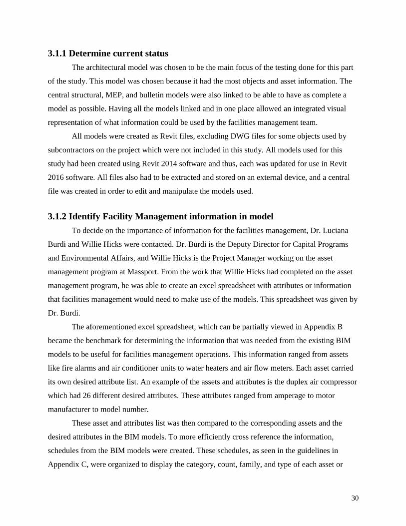
3.1.1 Determine current status
The architectural model was chosen to be the main focus of the testing done for this part
of the study. This model was chosen because it had the most objects and asset information. The
central structural, MEP, and bulletin models were also linked to be able to have as complete a
model as possible. Having all the models linked and in one place allowed an integrated visual
representation of what information could be used by the facilities management team.
All models were created as Revit files, excluding DWG files for some objects used by
subcontractors on the project which were not included in this study. All models used for this
study had been created using Revit 2014 software and thus, each was updated for use in Revit
2016 software. All files also had to be extracted and stored on an external device, and a central
file was created in order to edit and manipulate the models used.
3.1.2 Identify Facility Management information in model
To decide on the importance of information for the facilities management, Dr. Luciana
Burdi and Willie Hicks were contacted. Dr. Burdi is the Deputy Director for Capital Programs
and Environmental Affairs, and Willie Hicks is the Project Manager working on the asset
management program at Massport. From the work that Willie Hicks had completed on the asset
management program, he was able to create an excel spreadsheet with attributes or information
that facilities management would need to make use of the models. This spreadsheet was given by
Dr. Burdi.
The aforementioned excel spreadsheet, which can be partially viewed in Appendix B
became the benchmark for determining the information that was needed from the existing BIM
models to be useful for facilities management operations. This information ranged from assets
like fire alarms and air conditioner units to water heaters and air flow meters. Each asset carried
its own desired attribute list. An example of the assets and attributes is the duplex air compressor
which had 26 different desired attributes. These attributes ranged from amperage to motor
manufacturer to model number.
These asset and attributes list was then compared to the corresponding assets and the
desired attributes in the BIM models. To more efficiently cross reference the information,
schedules from the BIM models were created. These schedules, as seen in the guidelines in
Appendix C, were organized to display the category, count, family, and type of each asset or

31
object in the model. This was used as the preliminary comparison between the information in the
model and the information that the facilities management team wanted in the model.
3.2 Information Enrichment
To conduct the actual enrichment of the model itself, the team took different approaches
based on the specific situation of each attribute. When an attribute in the list from facility
management was not found in the model, it needed to be added by some means. The four
methods for object addition were loading existing objects, downloading existing objects,
modifying existing objects and creating new objects.
The first and simplest of the four options is loading an existing object. Attributes in this
category were already contained in the component tab of Revit software or they were placed in
the model previously. This method was used only when the object in the program was the proper
representation of the listed attribute. Minor changes such as names and spelling for existing
objects were carried out to assure the list matched the model sufficiently. An example of this is
seen below for the object of the defibrillator.
THIS SPACE HAS BEEN INTENTIONALLY LEFT BLANK.

32
Figure 20: Example of Loaded Existing Object
Modifying existing objects was the most common method used. When the object was not
in the model but an object in the same or similar family was found in the Revit library, then it
was loaded and modified. Since most of the objects for the purpose of facility management acted
as place holders and geometric shapes to hold information, the objects did not have to physically
match the detail of the actual objects. Therefore, the team was able to modify the name, and
family and categories when necessary, to assign the newly loaded object to the desired object
from the list. This method was used for the majority of assets. This was especially true for
objects of the same family such as panel board and air conditioner.

33
Figure 21: Example of Common Object
When an object was not located in the loaded components nor in the library of Revit, then
it was downloaded from an external object library such as RevitCity. When the needed object
was found, it was brought into the model and acted properly as any other object that would be
previously placed in the model.
The final method mentioned above, creating new objects, was employed the least of the
four for the refinement of the Framingham model. If an object listed on the desired asset lists was
not in the model, the library or on an external database, it had to be created. To do this, simple
geometry such as cubes were employed since the objects are place holders with LODs of 100
containing the crucial information for management of the space. The object was created in

34
AutoCAD and imported into the Revit library with the needed name, category and family to
assure success for the end product.
Once all the necessary objects identified on the facility management asset list were added
to the model the correct parameters and attributes were assigned to each. To do this, parameter
fields were created before they could be attached to object families. Each parameter would
appear when an object was selected and it would show a field next to the title of the parameter to
provide a space to enter in the specific data for that object selected.
Figure 22: Properties of Selected Asset after Attributes were added
For each unique parameter listed in the asset list, a parameter field was created. Through
the “Shared Parameters” function in Revit, the name and type of entry for the parameters were
designated. Once created, the parameter was then assigned to the appropriate categories for the
objects it had to identify. Also in this step, it could be designated under which section of the
object properties the parameter would be located. In Figure 23, below, the “Shared Parameters”
function is being used to add a parameter. The figure is adding the manufacturer parameter to the
Shared Parameters list. Figure 24

35
Figure 23: Window to Create Parameters
Figure 24: Window to Assign Parameters
The type option was used to assign the attributes. The parameters could either be added
based on type or instance, this means that the parameters’ entered data could be unique for each
type of object, so all air conditioners would have the same field, or by instance, so each
individual object would be able to have different field values. It is because of this step of
36
attaching the parameters, which made it so important to add or represent objects in the correct
categories. The parameters were not attached to each individual object but instead all objects in
the categories selected for the parameter would then contain the field. Throughout the
refinement, the team added 109 objects from the desired asset list and created over 100 unique
parameters to contain the data of the assets.
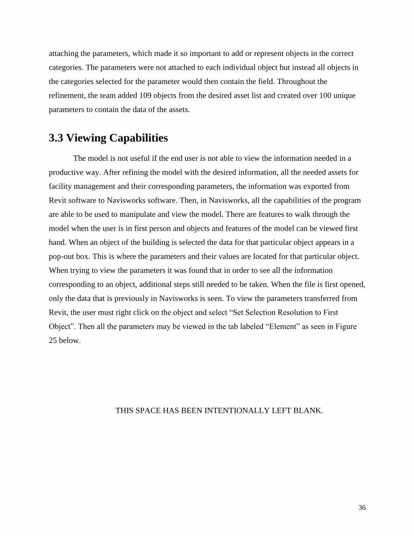
3.3 Viewing Capabilities
The model is not useful if the end user is not able to view the information needed in a
productive way. After refining the model with the desired information, all the needed assets for
facility management and their corresponding parameters, the information was exported from
Revit software to Navisworks software. Then, in Navisworks, all the capabilities of the program
are able to be used to manipulate and view the model. There are features to walk through the
model when the user is in first person and objects and features of the model can be viewed first
hand. When an object of the building is selected the data for that particular object appears in a
pop-out box. This is where the parameters and their values are located for that particular object.
When trying to view the parameters it was found that in order to see all the information
corresponding to an object, additional steps still needed to be taken. When the file is first opened,
only the data that is previously in Navisworks is seen. To view the parameters transferred from
Revit, the user must right click on the object and select “Set Selection Resolution to First
Object”. Then all the parameters may be viewed in the tab labeled “Element” as seen in Figure
25 below.
THIS SPACE HAS BEEN INTENTIONALLY LEFT BLANK.

37
Figure 25: Viewing Object Parameters in Navisworks
Navisworks is fairly user friendly and does not need significant training to use the simple
viewing capabilities. Currently, Massport is training a handful of project managers to better
understand the uses and applications of Navisworks. If Navisworks models are employed for
facility management operations then the personnel will be able to conduct an interactive
walkthrough through the model and view various objects. This allows the user to gain an
understanding of the location of the actual object, versus just have a serial number in a table
representing that particular object. Once the user locates the object, all the data added into the
Revit model may be easily accessed and viewed by simply pointing and clicking directly on the
object. If it is preferable, the user may even add more information or notes about the object in
question that will continue to be attached to the object in the Navisworks file.

38
4.0 Improved Process
The work developed in chapter 3 is intended to produce a model that can be used by
Facility Management; however, this was done after the design and construction BIM models
were created. Since most of the design and construction was done without the involvement of the
facility management team, the asset information need by FM was not included. This cause an
extra step of tagging and recording the data for the assets of the building, which is redundant and
time consuming since it is information that was much more accessible when the BIM models
were being created. Also, generally the information collected from the tagging is not always
incorporated into the models, so the models are never completed to the extent which facility
management needs. The solution proposed is an established template that may be given to the
different contractors or designers for a project.
4.1 Handover Process
To create the BIM model template, the team used the model that was refined, mentioned
above. This was the architectural model that had the structural, MEP, and bulletin models linked.
This model now contained all the objects loaded and the parameters created and attached. Once
saving the file as the template name, the team deleted all field values and items in the file so the
result was once again a blank file ready to be used for modeling. When the file was blank, it still
contained all the parameters the team had previously added. It also had the parameters connected
to the appropriate categories for objects defined in the refinement of the previous model. The
team saved the file not as a project but as a template so when a new project is opened, the user
may select this template to work from.
The purpose of creating a template is to assure that when the model is being created, all
the desired parameters are already contained in the file. Therefore, this allows the user to be
prompted with the correct attributes to complete when creating the model early on. So when an
object is added to the model when the as-built model is being created, the field to enter in the
specific data is there for use. The user does need to consider which attributes of the objects
would be helpful to the owner nor does he or she have to make the parameter his or herself
because the template contains all the necessary fields. This eliminates the need to obtain the data

39
after the fact because the information for each object is added into the model as the actual items
are purchased and installed by the contractor.
However, problems may arise with miscommunications or uncooperative parties. To
proactively prevent this, the required use of the template could be incorporated into the contract
created between Massport and the design contractor. Currently, the contracts require certain end
products, such as models in Revit, so the more complete models made from the given templates
is under the current workload requirements. If any parameter or object is not included in the
template for the particular project ahead of time then it may be added in manually once the
model is received from the contractor, using the steps mentioned in section 3.1 above. Although
the template may not contain all necessary attributes and assets, it eliminates the need to tag and
record all the objects of a building. By providing the initial template, only a handful of newly
identified unique or overlooked assets will have to be recorded retroactively versus the entire
array of assets as is the process currently being done.
4.2 Facility Management Operations
While considering solutions for the overarching problem of interoperability between
software, integration research was made to look into other possible options. The team
investigated various software and processes to consider for facility management use. Each option
was further researched and numerous benefits and limitations were determined. The below chart
displays the some possible integration tools and their evaluations.
THIS SPACE HAS BEEN INTENTIONALLY LEFT BLANK.

40
Table 1: Integration Software Evaluation
Program/Approach Benefits Limitations
Revit Editable
Various views
Require significant training
PDFs Simple
Minimum required training
Coordinated Steps
No 3D model
Paper
Maximo Currently used Not connected to model
EcoDomus Model viewing Requires training, not as common knowledge
BIM 360 Autodesk Product
Handheld App
Not limited by size of file (The Cloud)
Security (cloud application)
YouBIM Handheld App
Extensive capabilities
Large compatibility
New Product
Assemble Extensive capabilities Expensive
Navisworks User-Friendly
Current training in progress
Not backwards compatible
The driving factors in assessing the benefits of the alternative approach were the
practicality, learning curve, and interoperability of each option. Cost should be considered but it
was not included in this assessment since software is quoted on a project-based system.
Massport is currently using Autodesk Navisworks and IBM Maximo for asset viewing
and management. Although there is much value in the 3-dimensional aspects of BIM software,
the current use of PDF’s for asset location is the most widely used amongst the Facilities
Management staff. An additional software, EcoDomus, was researched for its ability to
automatically to bridge the gap between BIM and FM software.
The first program reviewed was Navisworks. As noted in section 3.2.1.3, Navisworks is
used to optimize scheduling through 4D and 5D modeling, detect clashes and create an
environment for communication between different trades. The ability to import files from an
array of diverse software enhances the use of Navisworks. It also gives options to different trades
work to use their preferred software; therefore, this platform lends itself to an easier adaptation
and interoperability. Since its main use is for visualization, most of its capabilities can be

41
understood with simple training. This makes this software easy to learn. In addition, its
capabilities to collect different types of files, show clashes, 4D and 5D simulations, and its user-
friendliness make this software very practical. The software’s current limitation is its inability to
edit model information for wider use with FM software.
IBM Maximo is currently also working towards bridging the gap between BIM and FM
software. An advantage of 3D models is the visual advantage for planning purposes. This
advantage allows the facility management staff to prepare the proper equipment and see the
location of an asset without needing to know how to get around a facility. An extension for
Maximo was released in January 2016 and focuses on the 3D model viewing capabilities of BIM
software. The model would be linked from BIM model software and can be used to look around
a model for assets and create work orders. The extension now allows Maximo to offer 3D asset
viewing capabilities. Although this enhances the possible integration of BIM and FM, it does not
address its inability to update asset information in the 3D models.
The Portable Document Format (PDF) is the most widely used digital format for 2D floor
plans and building information. This format allows large sheets of physical documents to be
converted into a digital format that can be more accessible and searchable. This allows facility
management staff to locate assets, but does not allow any information to be updated in the PDF
files. Bluebeam technology is also enhancing the capabilities of PDF’s. Bluebeam allows for
legends, batch markup summary, and document tab preview.
Although Massport is not currently using EcoDomus, it was researched as a possible
solution for bringing BIM and FM software into one software. This program has the capability of
showing 3D models from a variety of software programs; these can be but are not limited to
Navisworks files, Revit models, and Tekla files. As previously mentioned in section 2.3.3.1,
EcoDomus has the ability to integrate BIM model and FM software into one interface. This
allows work orders to be made while also being able to look up an asset on a 3D model and find
any details from that model about the asset. EcoDomus does well in allowing information to be
edited and updated in both FM software and BIM software. The current limitation is the creation
of new assets and the lack of standards for receiving information in anything other than COBie.
42
4.2.1 Experimental Solution to Software Data Integration
The current Autodesk Revit software does not have a direct connection with the Maximo
FM software. This has led to a missing link between the information created in Revit models and
the information that is constantly being updated for the asset management. The team researched
and worked on Revit to try and find a connection with the information-rich models and
Maximo’s asset database.
As aforementioned, Revit has a capability to create schedules of the assets or objects in
the model. From these schedules, any parameters previously added could be extracted into a
table. This table can then be exported from Revit as an excel spreadsheet.
Maximo’s asset management systems also has an export feature. This export feature has
several options but the team focused on the excel spreadsheet feature. Using the excel file from
Maximo, there are formats for the way Maximo can read information and these can be seen in
the exported excel spreadsheet. This then lends itself to some manipulation to bridge the gap
between the information from Maximo and the Revit models. When the excel file is updated, it
can be saved as a CSV file for use in either Maximo or Revit. Although it is currently not an
automatic software to software information exchange, this does allow for information to be
exported from each program and for manipulations to be made to update each system.
For this possibility, the collaboration of Maximo and Revit becomes more appealing for
the successful integration of BIM and FM software. This kind of manipulation however, takes
training, as it is not easy to understand. Understanding the way Maximo and Revit read the
spreadsheet files becomes the emphasis of training.
Using a template for the information format can increase how efficient and user-friendly
this process can become. This template, unlike the one proposed for the handover process, would
be used for the excel file to update the asset information between software. This helps take away
any extensive training that would need to be done for Revit, Maximo, or any other software
package as it shifts the technical knowledge from those packages and into a simpler Excel
spreadsheet.

43
5.0 Structural Analysis
The study was extended to explore extensions for BIM model interoperability for
structural design purposes. A structural review of the existing Framingham garage was
conducted. To do this, both hand calculations and software-aided analyses were conducted. The
pre-stressed double tees of the framing system for the garage were analyzed to assess the
appropriateness of the sizing and materials for the designated loads. The steel members of the
garage’s internal lobby area were also investigated to assure the capacities were sufficient. Once
completing the calculations by hand for the lobby area, the team created and analyzed the model
of the members using the software program, Robot Structural Analysis professional. The
information regarding the steps of these calculations and processes are further detailed in the
following sections.
5.1 Steel Frame Analysis
The team started the hand calculation by investigating the steel framing of the lobby.
Using the structural as-built models in Revit provided by Massport, the sizing and materials of
components were gathered. The section of the lobby that was chosen was a bay which was the
largest in the system that framed the boundaries of the lobby area. The bay itself is 37 feet 10
inches by 26 and a half feet. And it is supported by four W12x65 steel columns at the corners.
The beams which spanned between the columns were found to be W12x40 and the interior most
beams of the system are W12x19. The team also used the structural pdf drawing documents
given by Massport that were created during construction. These documents contain the
specifications of materials, capacities of components and loading conditions.
The appropriate beams for the scheme was determined from calculations for both the
plastic bending capacity and serviceability. The plastic bending capacity deals with the strength
of the member. At a certain point, when both the section of the member in tension and in
compression completely yield, a plastic hinge is formed. This hinge is located at the maximum
moment along the member in the fully plastic cross section. With the creation of this third hinge
in addition to the already existing two supporting hinges, the member will fail. Therefore, the
size and type of the member necessary to prevent this failure was calculated. The calculations

44
performed determined the uniform load, the plastic capacity and then the plastic section
modulus. Since this was a review of the capacity of the existing members, the team was able to
include the self-weight of the beams in the beginning calculations. The structural documents
revealed that the members supported the dead load of their own weight in addition to the
designated 100 pounds per square foot for the lobby area. If the calculations provide a value that
meets the requirements for the selected member, then that said member is appropriate for the
strength portion to support the system.
The second standard that was investigated to determine the proper beams was the
serviceability. This feature is related to the deflection of the members. The members were tested
to assure they can withstand the total load for the area. For this project 50% of the live loads
were used for the calculations and they were compared to the equations L/360 or 1 inch and
L/240 for the floor live load deflection and the total deflection. This check of serviceability
assures that the cross section of the member is able to withstand the tolerance of deflection for
the span.
Through the calculations using the provided pdf documents and the values in the AISC
Specifications, the team was able to conclude that the members were sufficient for their purpose
(AISC, 2013). Both sized members, the W12x19 and W12x40, were appropriate for strength
capacity and deflection resistance. Appendix E contains the in depth calculations and
computational processes.
5.2 Double Tee Analysis
The following component of the structure that was analyzed was the double tee beams.
These are pre-stressed concrete components that span between the columns of the garage. The
double tees span an average distance of 60 feet and are typically sized as seen in the documents
in Appendix D. Based on the material properties, geometry, loading and support of the members,
the team was able to calculate and distinguish the effectiveness. The team also used the
spreadsheet created by a previous MQP team comprised of Jose A. Cueva, Jean Pierre Miralda,
and Saadet Nur Yilmaz (Miralda, Cueva, & Yilmaz, 2015).
The creation of a pre-stressed member includes the pre-tensioning of the steel fibers
which are set in the concrete. These 7-wire strands are located below the center of gravity of the
member, so when the tensile force holding the strands is released, the bottom of the member

45
compresses and the top undergoes tensile forces. This causes the member to camber and gain a
visible deflection upwards. This is done so that when the additional loading is added, the
member’s top portion will go into compression from tension and the compression on the bottom
portion will decrease. The beam will bend back to a more horizontal direction and the affect is
that the member has a far larger strength capacity than general concrete (J. Rosewitz, Personal
Communication).
To begin, the structural documents were searched for dimensions, loading, and properties
that would be necessary for the calculations. The area designated to represent the structure’s
double tees was chosen as a section of the top level were the framing was assumed to be flat and
the loading was specified. The loading capacity was checked for three cases of the structure. The
areas included the parking with 40 psf of live loads, the terminal with 100 psf of live loads and
the roof with 20 psf of live loads. Due to the creation and logistics of pre-stressed concrete the
team had to check the capacity of the beam at various assumed stages in the usage of the
member. These stages are the capacity at release on both the end region and midspan region,
during formation of the member, and then also the capacity at the midspan while the member is
in service.
Using the PCI Design Handbook, the team assumed the diameter of the strand of steel in
the member was 0.6 inches and the calculations began with 8 strands in the double tee. The team
had to enter the proper geometry, properties and loading conditions in to the designated
equations to determine various components to contribute to the final evaluation of capacity.
These parts were the creep of the concrete, the elastic shortening, the shrinkage of the concrete
and the relaxation of the tendons (Miralda, Cueva, & Yilmaz, 2015).
Once the main sections were each calculated through the spreadsheet, the stresses on the
three designated conditions were found. To do this the individual stresses in different areas, such
as the top and bottom of the beams, were calculated and then combined to find the total stress on
the member during that condition. Based on guidelines and limits found in the PCI Handbook,
the stresses were designated as within the limits or not for effectiveness. When it was found that
the member did not fall within the limits or if the results showed the beam would be cracked,
inputs such as the number of strands and the eccentricity were adjusted to represent stronger
members.

46
As a result of the calculations it was found that with the largest loading, which would
correspond to the terminal section, the double tees need 20 strands so that it will meet the three
capacities for stress. All the calculations which relate to the work described in this section may
be found in Appendix F.
5.3 Robot Structural Analysis
The final component of the structural analysis for the project was to incorporate the
chosen steel framed portion of the lobby into the software program. From the BIM models
provided, the team was able to recreate the various members and columns for the designated bay.
In a separate Robot Structural Analysis file the bay was modeled to assure it was the only
component being analyzed and the geometry and connections were correct. The selected section
drawn in Robot Structural Analysis can be viewed below in Figure 26.
Figure 26: Lobby Framing Drawn in Robot
After designating the proper sizes and layout of the specified columns, beams and
girders, the loads had to be identified. The team found the factored loads that acted as distributed
loads on each beam from the structural documents and dimensions. By first identifying the type

47
of loading, the team was then able to assign a value to the loading conditions and apply them to
the corresponding members. The labeled distributed loads applied to each beam can be seen in
the figure below (Figure 27).
Figure 27: Loading Added to Structure in Robot
The final step of the analysis in the software was to simulate the calculations to obtain the
information about the members and load cases. The results from the calculations provided the
team with various data, such as moments, deflections and axial forces on the structure. These
results were comparable to the values obtained through the hand calculations.
While conducting this portion of the structural analysis, the following issues were
observed. BIM model configuration could not be exported successfully to Robot Structural
Analysis because the anylitical model did not meet all conditions for proper export. As a result
the geometry of the frame was recreated within Robot itself. This also proved difficult because
each node had to be added by specifying the x, y and z coordinates for each. The graphic user
interface of this software is not very user friendly in the sense of creating the model. Other than
that, there are a few beneficial features such as adding a dead load to represent the self-weight of

48
each member on the system was very useful. Also, the results which the program collects are
very extensive and, when understood and used properly, can be very applicable.

49
6.0 Conclusions and Recommendations
The team focused on improving the effectiveness and usability of BIM technology for
Facilities Management. This chapter will state the conclusions drawn from the project and
recommendations the team has for future BIM Facilities Management work. This will include the
improvements for the handover process for better resource attainment for facility management
and the investigation on practices to improve facility management for building operations.
6.1 Improved Handover Process
Through the investigation of current processes being used by Massport for their projects,
the team learned that the facilities management team, which would find the BIM software most
beneficial, is not involved early in the construction process. This leads to a retroactive approach
for the facilities management team. Any information that is needed for the assets must be located
through the many files of warranties and asset–specific information. Without early engagement
from the FM team, the models become more difficult to use and less practical as the required
information has not been connected to the assets in the models. The new handover process
guidelines, which can be found in Appendix C, created for this project can be seen in the
following sections below and are the recommendations for improving the handover process and
BIM usage in facilities management.
6.1.2 Contract with Template
The team reviewed the workflow used for inputting information and concluded that a
systematic approach would be most appropriate to improve the handover process. The current
workflow does not require the facility management team to work early on in the design or
construction process. Having the FM team included early in the process would allow the team to
create or customize model templates for the project. This process would give the data integration
team an opportunity to focus on creating or editing the parameters desired in the model for the
facilities management use. The model template or template file would be contractually used
throughout the design and construction phase to collect the data during installation of assets
versus retroactively. Doing this would in effect lead to a BIM model that is not only accurate but
is also rich in valuable and up-to-date information. This template-based system should

50
theoretically work for decreasing the amount of time that is used in ensuring that desired
parameters are in the models by populating models early on with information attached to the
objects.
6.2 Improved Facility Management Operations
The current software programs used for facility management and BIM may require an
extensive training program. For this reason, many FM users do not become familiar with the
software or technology that is presented throughout the different BIM platforms. Even when
information can become very impactful and powerful, the complexity of programs like Autodesk
Revit can discourage FM employees from accessing information in the BIM models. Another
important aspect to consider when investigating FM software and processes is the cost of the
platform. When investigating a possible integration option for the use in facility management
operations, the team conducted a pros and con analysis on various items, including factors such
as practically, cost and benefits.
6.2.1 Recommended Integration Software and Further Research
From the integration research and the final presentation at Massport, it became evident
that the user-friendliness of the software is one of the most important driving forces in the
adaptability of the software. The current use of PDF files for 2D floor plans lends itself to the
traditional format of searching for asset location and information. This information will tend to
become outdated overtime, and without a way to edit the information on PDF files, the
maintenance of the assets will become increasingly more difficult. It is recommended that 3D
modeling software be used to create as-built models and that these are maintained to ensure the
information is accurate. By keeping the 3D models accurate, 2D floor plans can be created with
the most updated information for facility management staff to use. These are possible solutions
while the technology improves. Once there is software that can be user-friendly for any staff
member to confidently use and find value in, there can be a transition towards 3D BIM and FM
software use. This transition can also be sped up with investment in training that focuses equally
on the software needed to learn and the value that each staff member can receive from learning
and using the new software-based process.

51
6.3 Structural Analysis
The additional component incorporated in the work of this project was the structural
analysis. A structural review of various systems throughout the garage was conducted. Through
hand calculations, the effectiveness of the steel framing for the lobby area and the double tees of
the structure evaluated. The Robot Structural Analysis software was used to investigate the
interoperability between it and Revit, and also to confirm the results of the review for the lobby’s
steel framing. Through the three methods, the differing sections and components were all
determined to be designed effectively for the loadings and the purposes designated.
6.3.1 Recommendations for Structural Analysis Procedures
For future analyses of structural systems of this nature, further research into the
interoperability capabilities of Robot Structural Analysis or a different software program is
recommended. In this study the use of Robot in this way was efficient or effective. However,
with further research and training of the capabilities and uses, the program may prove to be
beneficial in the future. It is also suggested to investigate different software packages that may
have more comprehensive applications and BIM interoperability features.
6.4 General Recommendations
Throughout the project, there were some inherent obstacles in working with the files for
the Framingham garage because there is no backwards compatibility for Autodesk Revit. The
first step was to update all the files to Revit 2016 files. It is recommended that files be kept with
the most up-to-date software packages as any older versions may become obsolete. Any work
done by subcontractors, project managers, designers, and other members of a project must be
usable in a specified open format.

52
Bibliography
AECbytes. (2013). “Revit 2014.” Retrieved from
http://www.aecbytes.com/review/2013/Revit2014.html
Alvarez-Romero, S. O. (2014). Use of building information modeling technology in the
integration of the handover process and facilities management. Worcester, Mass: Worcester
Polytechnic Institute.
American Institute of Steel Construction. (2013). Steel Construction Manual. 14th Edition.
ArchiCAD. (2015). “ArchiCAD.” Retrieved from
http://imag.malavida.com/mvimgbig/download/archicad-1479-1.jpg
Autodesk. (2011). “User Interface.” Retrieved from http://knowledge.autodesk.com/search-
result/caas/vhelp/help-dev-autodesk-com/v/Revit/enu/2012/Help/Revit-User-s-Guide/0005-
Introduc5/0018-User-Int18.html
Autodesk. (2013). “Autodesk Revit.” Retrieved from http://down.cd/images/apps/Autodesk-
Revit-2013-5723.jpg
Autodesk (2015a). “AutoCAD MEP: Electrical and plumbing design software.” Retrieved from
http://www.autodesk.com/products/autocad-mep/features/all/gallery-view
Autodesk. (2015b). “Navisworks.” Retrieved from
http://www.autodesk.com/products/navisworks/features/all/gallery-view
Autodesk. (2015c). “Collaborative Construction Management Software.” Retrieved from
http://www.autodesk.com/products/bim-360/overview
Benson, B. (2015). “New Logan Express Garage to Open in Framingham Thursday.” The
Metrowest Daily News. Retrieved from
http://www.metrowestdailynews.com/article/20150414/NEWS/150418031
Bentley (2015). “Hevacomp Mechanical Designer V8i.” Retrieved from
http://www.bentley.com/en-US/Products/Hevacomp+Mechanical+Designer/
BIM Forum. (2013). “Level of Development Specification.” Retrieved from
http://bimforum.org/wp-content/uploads/2013/08/2013-LOD-Specification.pdf

53
Burdi, L. (2011). “BIM: Why, What and How- The Commonwealth of Massachusetts’
Approach.” Presentation.
CADTutor. (2012). “Autodesk BIM 360 Glue.” Retrieved from
http://www.cadtutor.net/forum/showthread.php?73284-The-Navisworks-Mobile-App-is-Now-
Available-for-the-iPad-Autodesk-BIM-360-Glue
Cantonese. (2014). “Autodesk Revit MEP.” Retrieved from
http://www.arksystems.fi/revitm13l.jpg
Cortes, E. (2012). “HVAC Design with Bentley Building Mechanical Systems.” Retrieved from
http://i.ytimg.com/vi/Pf6FN_xWLtA/maxresdefault.jpg
East, W. (2012). “Construction-Operations Building information exchange (COBie).”
buildingSMART alliance.
EcoDomus. (2015). “BIM Software for Lifecycle Facilities Management.” Retrieved from
http://www.ecodomus.com/index.php/ecodomus-fm/
ENGworks BIM. (2013). “BIM for Facility Management-YouBIM-Cloud based solution.”
Retrieved from http://youbim.com/video.html
ENGworks BIM. (2015). “Features.” Retrieved from
http://youbim.com/features.html#attacheddocuments
Foster, B. (2011). “BIM for Facility Management: Design for Maintenance Strategy.” Journal of
Building Information Modeling, (Spring 2011), pp.18–19.
Gaudiosi, J. (2015). “How this 150-year-old company uses virtual reality.” Retrieved from
http://fortune.com/2015/08/25/mccarthy-construction-vr/
IBM. (2015). “Maximo Asset Management.” Retrieved from http://www-
03.ibm.com/software/products/en/maximoassetmanagement
Khemlani, L. (2012). “IFC Tools Feature in the Autodesk University Review.” Retrieved from
https://revitall.wordpress.com/tag/solibri/
Massport. (2015a). “History.” Retrieved from https://www.massport.com/logan-airport/about-
logan/history/
54
Massport. (2015b). “About Massport.” Retrieved from https://www.massport.com/about-
massport/about-massport/
Massport. (2015c). “Massport BIM Roadmap.” Retrieved from
https://www.massport.com/media/336989/Massport-BIM-Roadmap-Poster-2015-Update.pdf
Master Graphics Inc. (2012). “What’s New in Navisworks 2013 Part 2-Timeliner.” Retrieved
from https://www.youtube.com/watch?v=PJb8rDccnPU
McGraw-Hill Construction, (2012) “The Business Value of BIM in North America: Multi-Year
Trend Analysis and User Ratings (2007-2012)” Retrieved from
http://bimforum.org/wpcontent/uploads/2012/12/MHC-Business-Value-of-BIM-in-North-
America-2007-2012-SMR.pdf
McPhee, A. (2013). “Practical BIM: practical tips on making BIM work.” Retrieved from
http://practicalbim.blogspot.com/2013/03/what-is-this-thing-called-lod.html
Miralda, J.P., Cueva, J., & Yilmaz, S. (2015). CitySquare Underground Parking Garage.
Worcester, MA: Worcester Polytechnic Institute. Retrieved from http://wpi.summon.
serialssolutions.com/#!/search?bookMark=ePnHCXMw42LgTQStzc4rAe_hSuFkUHUGtieDC4
E-TlUAX-YD2q-Ql6IA2tYLLJ4V3BOLwPvbpdxcQ5w9dMsLMuOhQxfxRhZmoL2
TxnglAXCEJEs
NBIMS. (2015). “National BIM Standard-United States.” Retrieved from
https://www.nationalbimstandard.org/files/NBIMS-US_FactSheet_2015.pdf
OmniClass. (2015). “Background.” Retrieved from http://www.omniclass.org/background.asp
PRWeb. (2015). “Total Resource Management Unveils RulesManager 4.0.” Retrieved from
http://www.prweb.com/releases/2009/07/prweb2694864.htm
Starkov, I. & Griffith, H. (2011). “Building Lifecycle Data Management Enabled by COBie and
BIM.” Presentation.
Syncronia. (2011). “Autodesk BIM Conference 2011.” Retrieved from
http://blog.syncronia.com/en/autodesk-bim-conference-2011/
Tekla. (2015a). “Tekla Promotes Open Approach to BIM.” Retrieved from
http://www.tekla.com/company/building-construction/Open-BIM

55
Tekla. (2015b). “Tekla Structural Designer.” Retrieved from
http://www.tekla.com/sg/products/tekla-structural-designer
Walker, P. (2015). “BIM 360 Glue- New 2d map Feature for Intuitive Location Navigation.”
Retrieved from http://www.bim360.com/blog/2015/02/bim-360-glue-new-2d-map-feature-for-
intuitive-location-navigation-2/

56
Appendix
Appendix A: E-Files
Throughout the course of this project the team used and created numerous E-files. The list below
describes the files submitted with the report to help further clarify any components of the work.
Zipped File Folder- Final FILES
Revit Files
o Revit_Files -This internal folder contains all the Revit files that were revised for
the project.
o ARCHITECTURAL_LEXF_TERMINAL_CENTRAL_Bulletin18-GOLD-
TEMPLATE.rte –This the template created by the team to improve the attainment
of data through the handover process.
Navisworks Files –These are the files which were created to view the models in
Navisworks.
o ARCHITECTURAL_LEXF_TERMINAL_CENTRAL_Bulletin18-GOLD.nwc
o ARCHITECTURAL_LEXF_TERMINAL_CENTRAL_Bulletin18-GOLD.nwd
Excel of Attributes –This file is the original excel file containing the parameters and
assets provided by Massport that was used to revise the models.
o Asset Class with Attributes
Excel for Double Tees –This file contains the calculations for the double tee structural
review.
o Analysis of Double Tees
Robot Structural files – This file includes the work and analysis made with the Robot
Structural Analysis software.

57
Appendix B: Sample of Asset Attribute Spreadsheet

58
Appendix C: Guidelines on How to Add Parameters, Attributes,
Schedules, and Exporting Data into Excel
Depending on the editing rights the user may have, the file may not be edited or used for
anything than the visual content. To allow edits to be made and saved from a new user, the file
must be “detach from central.”
After clicking “open” for the selected file, Revit will ask if you would like to preserve or detach
the worksheets in the document. Using the “preserve worksheet” option allows previous
worksets to be used and a new central model to be created.
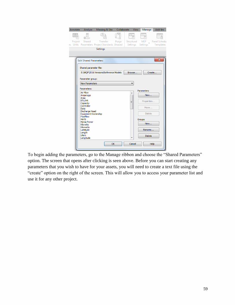
59
To begin adding the parameters, go to the Manage ribbon and choose the “Shared Parameters”
option. The screen that opens after clicking is seen above. Before you can start creating any
parameters that you wish to have for your assets, you will need to create a text file using the
“create” option on the right of the screen. This will allow you to access your parameter list and
use it for any other project.
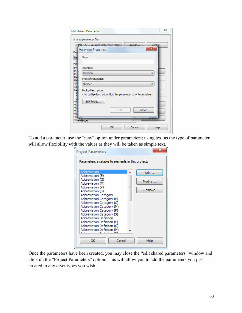
60
To add a parameter, use the “new” option under parameters; using text as the type of parameter
will allow flexibility with the values as they will be taken as simple text.
Once the parameters have been created, you may close the “edit shared parameters” window and
click on the “Project Parameters” option. This will allow you to add the parameters you just
created to any asset types you wish.

61
To insert the parameters you just created, click on the radio button with “Shared Parameters.”
From here you will be able to add all of the parameters and choose the asset categories that will
need the parameter. Clicking the type option is recommended for a parameter that will hold the
same value across all the assets designated with that parameter; if you would like to vary the
values in the parameters across different assets, use the instance option.
One of the most useful asset organization tools is creating schedules with the assets and
the parameters wanted. To do this, click on the analyze ribbon and then on the

62
“Schedule/Quantities” option. This will open a window from which you may create a new
schedule with the name you wish.
After creating a new schedule name, add the fields that you wish to have shown. These end up
being your parameters and may include Name, Family and Type, and Quantity as some of the
basic description information. You may add as many parameters as you wish to extract more
information.

63

64
By going to the “Modify Schedule/Quantities” ribbon, you may use the “highlight in model”
option and this will allow you to view the asset in the model.
From here, you may export the schedule from the “File” “Export” option. By clicking okay for
schedule appearance and continuing by licking next and finish, the file will be exported as a text
file that may be imported to an Excel spreadsheet.

65

66

67

68
Appendix D: Structural Document Components
Loadings from Structural PDF documents for the areas of the structure
Double Tee Schematic
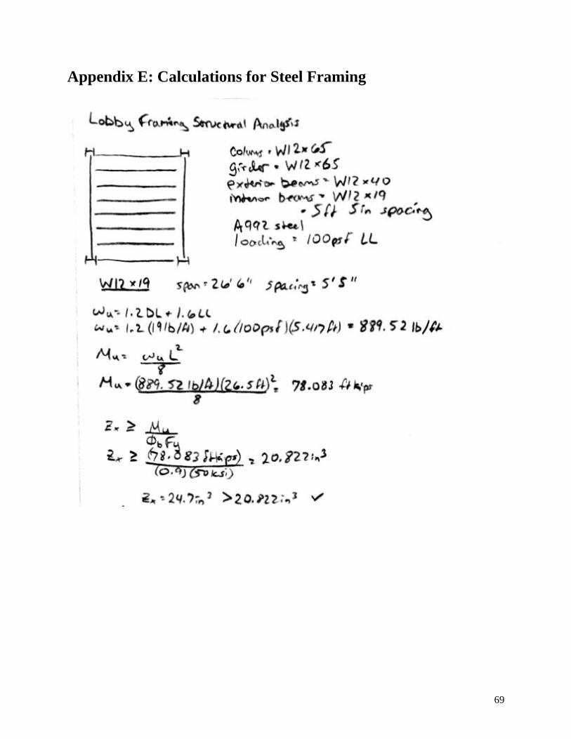
69
Appendix E: Calculations for Steel Framing

70

71
Appendix F: Calculations and Corresponding Spreadsheet for
Double Tees

72

73
Appendix G: Additional Robot Structure Analysis Components
Below are the results from the simulation calculations the team ran through Robot Structural
Analysis Professional.

74
Appendix H: Project Proposal
Innovative Uses of BIM for
Facility Management
Kristen Hunt
Juan Torres Betancur
Submitted to:
Professor Guillermo Salazar
3/4/2015
Worcester Polytechnic Institute
Massachusetts Port Authority

75

76
Table of Contents
1.0 Introduction ............................................................................................................................... 1
2.0 Background ............................................................................................................................... 4
2.1 What is BIM? ........................................................................................................................ 4
2.2 Massport ................................................................................................................................ 7
2.2.1 Massport History and Overview ..................................................................................... 7
2.2.2 Massport’s Implementation of BIM ............................................................................... 7
2.2.3 The Future of Massport with BIM .................................................................................. 8
2.3 BIM-FM Integration Software .............................................................................................. 8
2.3.1 BIM Software ................................................................................................................. 9
2.3.2 FM Software ................................................................................................................. 17
2.3.3 Integration Software ..................................................................................................... 18
2.4 Innovated Concepts of BIM ................................................................................................ 22
2.4.1 Augmented or Virtual Reality with BIM ...................................................................... 22
2.4.2 BIM Location Services ................................................................................................. 23
2.4.3 Construction Integrated for FM .................................................................................... 24
2.5 Conclusion ........................................................................................................................... 25
3.0 Methodology ........................................................................................................................... 26
3.1 Evaluate Facility Management and Model.......................................................................... 26
3.1.1 Determine current status ............................................................................................... 26
3.1.2 Identify FM information in model ................................................................................ 27
3.2 Refine Model for Facility Management .............................................................................. 28
3.3 Investigate and Prepare for Integration ............................................................................... 28
3.4 Provide Recommendations .................................................................................................. 29

1
Table of Figures
Figure 1: Graphical Representation of Tsunami Effect (Adapted from Alvarez-Romero, 2014) .. 2
Figure 2: BIM through the lifecycle of a building .......................................................................... 4
Figure 3: Level of Detail Examples ................................................................................................ 6
Figure 4: Revit Architecture Interface (http://down.cd/images/apps/Autodesk-Revit-2013-
5723.jpg) ....................................................................................................................................... 10
Figure 5: ArchiCAD Interface (http://imag.malavida.com/mvimgbig/download/archicad-1479-
1.jpg) ............................................................................................................................................. 11
Figure 6: Revit MEP Interface ...................................................................................................... 12
Figure 7: Bentley Hevacomp Interface ......................................................................................... 13
Figure 8: Revit Structure Interface ............................................................................................... 14
Figure 9: Tekla Structure Interface ............................................................................................... 15
Figure 10: Naviswork Interface .................................................................................................... 16
Figure 11: Solibri Code Checker Interface ................................................................................... 17
Figure 12: Maximo Interface ........................................................................................................ 18
Figure 13: Ecodomus Interface ..................................................................................................... 19
Figure 14: Version of BIM 360 .................................................................................................... 20
Figure 15: BIM 360 Interface ....................................................................................................... 21
Figure 16: YouBIM Interface ....................................................................................................... 22
Figure 17: Virtual Reality Demonstration .................................................................................... 23
Figure 18: 2D and 3D Map Locations Services on BIM 360 Glue .............................................. 24
Figure 19: Model with Outlined Guideline Attributes .................................................................. 25
1
1.0 Introduction
The Architecture, Engineering and Construction Industry was revolutionized with the
implementation of Building Information Modeling (BIM). The construction industry has seen an
increase from 28% to 71% in usage from 2008 to 2013 (McGraw-Hill Construction, 2012). BIM
increases communication and organization while decreasing the inefficiencies of the industry
such as unplanned difficulties with processes and interfering components. The implementations
of the improving technology of BIM allow companies to see “faster project approvals, increased
positive client interactions and higher client satisfaction” (Gaudiosi, 2015). The programs and
uses of BIM are continually advancing to include new applications and purposes.
BIM is valuable to numerous professions throughout the lifecycle of a building. It is
employed for the design, construction, operation and renovation phases for any given building or
structure. Multiple software have been developed to provide the capabilities for each of the
phases and professions. Specific programs highlight and focus the needs for the particular
function. Between phases the models and information must travel between different
professionals and also possibly different software. This handover segment of the lifecycle of a
building, like other aspects included in BIM is improving and being researched for efficient
practices.
The handover process between the design and construction phase to the operation and
maintenance phase of the building can contain large amounts of information that have value to
different people. One portion of this handover process that is detrimentally affecting the process
is a concept referred to as the tsunami effect. The tsunami effect explains how the model from
the creation of the building has all the information needed for the structural analysis,
construction, design and other components of the building that may not be crucial for its
operation after completion, as seen on the left half of Figure 1 below.

2
Figure 28: Graphical Representation of Tsunami Effect (Adapted from Alvarez-Romero, 2014)
All of this extra information, from the perspective of the facility manager, is the tsunami
that has to be cut down and refined to accommodate the team for maintaining the building. The
remaining information still useful to the facility management process is the blue rectangle on the
right half of the figure above. On the other hand, some information needed for the processes after
the completion of the building may not be included in the model handover because it was not
originally vital for the design or construction. Therefore, the attributes would have to be added
for the model to benefit the facility management team and this is included in the figure above as
the red rectangle.
Based on this concept of the tsunami effect and the goals of Massport, the team
developed the purpose of this project. The focus will be to refine and prepare Facilities
Management Building Information Models to more efficiently serve the lifecycle functions for
operation, maintenance and space utilization of a constructed facility.
The team will refine a preliminary model, provided by Massport, to facilitate the facility
management operations and prepare the model for integration with facility management (FM)
software to improve efficiency of the facility management process. To do this the team will
distinguish the necessary and unnecessary attributes included and not included in the current
provided model. Then, the current model will be refined to meet the requirements for the purpose
of facility management, and lastly, the team will prepare the modified model for integration
software to improve for facility management use.

3
The project will result in a modified model with the desired attributes, research of BIM-
FM integration systems and piloted software with the prepared model.

4
2.0 Background
2.1 What is BIM?
BIM, which stands for Building Information Modeling, is a concept used to incorporate
the information and data for a building into an interactive model created on software. According
to National BIM Standard (NBIMS), “a building information model is a 3D digital representation
of physical and functional characteristics of a facility. As such it serves as a shared knowledge
resource for information about a facility forming a reliable basis for decisions during its lifecycle
from inception onward” (NBIMS, 2015).
Building information modeling is not necessarily a new technology but in recent years
numerous new applications with BIM have come about. “The adoption of BIM has grown from
28% to 71% in the construction industry between 2008 and 2013 in the first and second BIM
SmartMarket Report research studies, published by McGraw-Hill Construction in 2006 and
2009” (McGraw-Hill Construction, 2012). BIM has a wide range of uses for professions across
fields of practice. BIM can be used for the design, construction, and maintenance and operation
of the building. The graphic below in Figure 2 displays the uses of BIM throughout the life of a
building.
Figure 29: BIM through the lifecycle of a building (Syncronia, 2011)

5
The architect may use BIM to initially design the building before creation. The civil
engineer or structural engineer will take the design and continue using the BIM process to
calculate the infrastructure and materials needed for a stable building. Along the way other
engineers may perform analyses, such as energy loss and orientation on the site. BIM programs
can also be used for the scheduling and cost analysis for the project manager. And then after the
model is implemented to complete construction, the model will be transferred for application for
the operation of the building. The model can continue through the steps of use multiple times in
the case of renovations. BIM is a valuable asset for the life-cycle of the building.
Models are made for numerous profession and purposes; therefore they differ on different
levels. During creation and after completion the product is modified for each use, not only is the
content and software specific but also the amount and formation of information is geared towards
the function of the model. The amount of information or detail in a model can be referenced
through the Level of Detail (LoD). LoD can also be Level of Development, which “is the degree
to which the element’s geometry and attached information has been thought through- the degree
to which project team members may rely on the information when using the model” (BIM
Forum, 2013). LoDs are rated on a number scale and different levels along the scale represent
specified descriptions for the corresponding details. Common ratings are 100, 200, 300, 350,
400, and 500. Level 0 signifies an item not modeled, level 100 refers to a conceptual model, and
level 200 is a generic or representational model and the details increase in amount and value as
the levels increase. Level 500 would correspond to a record model (Burdi, 2011). Examples of
the detail included in certain levels can be viewed in Figure 3 below (BIM Forum, 2013).
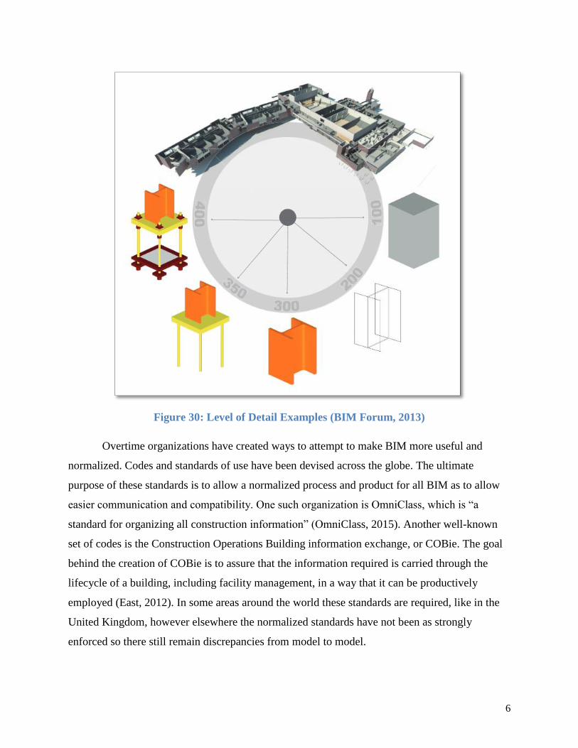
6
Figure 30: Level of Detail Examples (BIM Forum, 2013)
Overtime organizations have created ways to attempt to make BIM more useful and
normalized. Codes and standards of use have been devised across the globe. The ultimate
purpose of these standards is to allow a normalized process and product for all BIM as to allow
easier communication and compatibility. One such organization is OmniClass, which is “a
standard for organizing all construction information” (OmniClass, 2015). Another well-known
set of codes is the Construction Operations Building information exchange, or COBie. The goal
behind the creation of COBie is to assure that the information required is carried through the
lifecycle of a building, including facility management, in a way that it can be productively
employed (East, 2012). In some areas around the world these standards are required, like in the
United Kingdom, however elsewhere the normalized standards have not been as strongly
enforced so there still remain discrepancies from model to model.
7
2.2 Massport
For the duration of the project, the team will be collaborating with Massachusetts Port
Authority, commonly known as Massport, at Boston Logan International Airport. Massport is an
independent public authority dealing with transportation means throughout Massachusetts. As
any organization responsible for facilities or buildings, in the modern technology age, Massport
has turned to innovative software for efficient operation. The sections following will set the
scene for Massport, its current BIM usage and its future endeavors.
2.2.1 Massport History and Overview
Massport was established in 1956 and became operational on February 17, 1959. It was
created as an independent public authority as not to draw funds from the government or the
taxpaying people. At the time of its creation, it was able to fund and sustain itself through “the
sale of revenue bonds, charges to users of its facilities and income from investments” (Massport,
2015a). Today Massport is “a world class organization of people moving people and goods –
and connecting Massachusetts and New England to the world – safely and securely and with a
commitment to our neighboring communities” (Massport, 2015b). Under Massport’s jurisdiction
is Boston Logan International Airport, Worcester Airport, Hanscom Field, Port of Boston and
numerous other properties.
Logan International Airport, located in Boston Massachusetts, provides flights to more
than 100 countries and areas around the world through the collaboration with nearly 50 airline
companies (Massport, 2015b). First opened in 1923 and officially named the General Edward
Lawrence Logan Airport in 1943, the airport has had numerous expansions and advances in its
field through the ninety plus years (Massport, 2015a). Logan Airport currently has four terminals
and local parking garage structures. The most recent completion to the complex at Logan Airport
was the parking garage.
2.2.2 Massport’s Implementation of BIM
Recently, Massport has been implementing various stages and uses of BIM. Models have
been created of the new constructed parking garage and one of the terminals. These models were
developed following the completed construction to represent the as-built situations; however,
they are in the phase before modifications are enacted for facility management use. Before these
8
models are refined for the utilization in the operations of the building, the proper information and
attributes of certain components have to be collected. Massport is working with two companies
using three different techniques to gather the desired attributes that will be included in the model
for facility management (Burdi, Personal Communication, 2015). In the past years, facility
management teams at Logan Airport have been operating with IBM Maximo. But the full
potential of the benefits of models and BIM have not been explored to improve these processes.
2.2.3 The Future of Massport with BIM
Teams working with BIM at Massport have created a Massport Building Information
Modeling Roadmap for the current and future implementation of BIM. The roadmap explains
key areas where BIM can improve throughout Massport. Massport’s mission for BIM is stated
below:
“Massport will utilize BIM and related technologies to empower its staff and
service providers to design and build outstanding structures, and then manage and sustain
these facilities and assets to meet Massport’s mission. As stewards of these digital assets,
Massport will maintain BIM,GIS, and facility maintenance asset data to support strategic
planning, sound decisions, sustainability, environmental responsiveness, and improved
processes to add value to managing the building lifecycle, and to aid Massport in better
reinvestment of available funds based upon organizational missions and operational
requirements” (Massport, 2015c).
Down the road the ideal result for Massport would be to have a BIM portfolio complete
to 100% with reliable data and access to personnel to maximize efficiency. Steps along the way
included in the roadmap are to “normalize BIM based project management and project
management training, optimize BIM to FM- integrated asset management, and institutionalize
enterprise asset management” (Massport, 2015c). These three phases are distributed through
smaller goals outlined on a timeline spanning from 2014 to 2020 within the roadmap. The
roadmap can be viewed through the Massport website.
2.3 BIM-FM Integration Software
Throughout the history of computer aided building design, the programs, applications and
software have continued to specify and improve for different desires. All components of the
9
design, construction and operation of a building can be documented and displayed through
software. Depending on the need of the user and purpose of the information, certain types of
programs are more suitable than others. This section explores the software of BIM, FM and
integrators: their purposes, features, benefits and capabilities.
2.3.1 BIM Software
The different sectors of construction require specialized BIM software, and although
many are compatible with each other, each software program is not interchangeable. This section
will focus on widely used BIM software programs in architecture, MEP (mechanical, electrical,
and plumbing), structures, and construction. All of these programs create data for the final BIM
project and thus, it is very important to understand the common uses and capabilities of these
programs.
2.3.1.1 Architecture
There are two very popular architecture programs used in the construction industry. Each
has different functionality but tend to reach a similar conclusion with the product. The first that
this section will cover is Revit Architecture by Autodesk, and then ArchiCAD by Graphisoft.
Revit Architecture focuses on the capability to create different architectural features such
as a curtain wall, floor, roof, room and area, stairs, anti-aliasing and loadable component for
design. The primary use of Revit Architecture is for a firm to create a 3D representation of the
model that they believe the owner is visualizing. Since this software is from the Autodesk
family, it is easily transferred into other Autodesk programs such as: Revit MEP, Revit Structure,
and Navisworks. This program is made to be flexible with the design features. It is designed to
allow the user to easily fix wall joints and the loadable components such as doors and windows.
Revit Architecture also has a layout of phase and phase filters. This allows the user to easily see
the process of either demolition or construction. Its 3D feature is axonometric as well, which
constricts the ease of virtually walking around the building or structure designed (AE, 2013).
Although ArchiCAD is similar to Revit Architecture in that it focuses on the designing of
a structure for an owner, ArchiCAD has a more intuitive layout for its commands. It has
perspective views that embrace the option to virtually walk around the designed structure. There
are also drafting tools that easily incorporate the option of elevations and sections, and the

10
energy modeling systems work well. However, the energy modeling is not as powerful as the
Ecotect and Green Building Studio from Revit Architecture (AE, 2013).
For the most part, there are advantages to each. While ArchiCAD has working templates
that do not leave the user starting from the creation of templates and standards, Revit
Architecture can easily convert to AutoCAD, and this is the program most widely used in the
industry. In Figure 4 and 5, below, you can see side-by-side comparisons of the layout for both
Revit Architecture and ArchiCAD.
Figure 31: Revit Architecture Interface (Autodesk, 2013)

11
Figure 32: ArchiCAD Interface (ArchiCAD, 2015)
3.2.1.2 MEP
MEP stands for mechanical, electrical, and plumbing. This important component of a
construction project is often coordinated through collaboration in BIM because of the
visualization capabilities of the BIM models. The models can help each line of work find clashes
in the design of the mechanical, electrical, and plumbing systems. This allows foresight in the
designing process since the clash is detected before the construction is undertaken, effectively
reducing related costs and time.
Two popular programs for this kind of coordination are Autodesk Revit MEP and
Bentley Hevacomp Mechanical Designer. Both focus on the MEP coordination and energy
analysis of a design but have different layouts that end up affecting the learning curve of the
software.
Revit MEP follows the same interface as the other Revit software programs. This allows
a user who is familiar with the other Revit software programs to easily understand and use the
MEP program. The main purpose of the MEP version is to “help mechanical, electrical, and
plumbing engineers keep design data coordinated, minimize errors, and experience enhanced
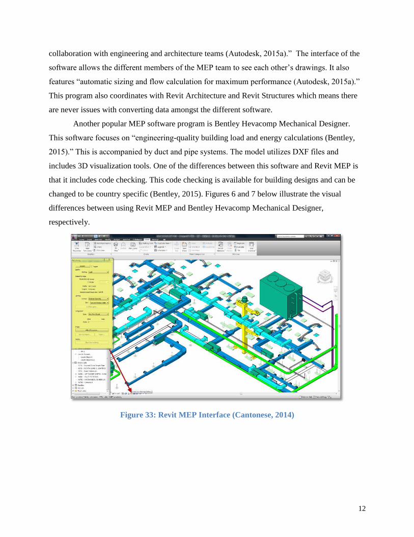
12
collaboration with engineering and architecture teams (Autodesk, 2015a).” The interface of the
software allows the different members of the MEP team to see each other’s drawings. It also
features “automatic sizing and flow calculation for maximum performance (Autodesk, 2015a).”
This program also coordinates with Revit Architecture and Revit Structures which means there
are never issues with converting data amongst the different software.
Another popular MEP software program is Bentley Hevacomp Mechanical Designer.
This software focuses on “engineering-quality building load and energy calculations (Bentley,
2015).” This is accompanied by duct and pipe systems. The model utilizes DXF files and
includes 3D visualization tools. One of the differences between this software and Revit MEP is
that it includes code checking. This code checking is available for building designs and can be
changed to be country specific (Bentley, 2015). Figures 6 and 7 below illustrate the visual
differences between using Revit MEP and Bentley Hevacomp Mechanical Designer,
respectively.
Figure 33: Revit MEP Interface (Cantonese, 2014)

13
Figure 34: Bentley Hevacomp Interface (Cortes, 2012)
3.2.1.3 Structure
The structural analysis of a project has been evolving with the introduction of BIM
structural capabilities. Not only can projects be designed through BIM software, specifications of
materials, dimensions, and structural analysis can also be incorporated into the construction and
design phase. Two programs that work on this structural field are Autodesk Revit Structure and
Tekla Structures.
Autodesk Revit Structure is another version of the Autodesk family. As with the other
Revit programs, there is smooth interoperability between Revit Structure and other Revit
programs such as Revit Architecture and Revit MEP. The addition of Robot Analysis makes
Revit Structure very capable analysis software. The Robot Analysis is the extension that allows
Revit Structure to perform the structural analysis of a given project. Revit Structure also focuses
on the ability to create engineered beams and project-unique components. This asset gives the
user the flexibility to engineer complex projects. The Revit interface for Revit Structure also
improves the capacity to engage in large project files. Figure 8 below shows the interface of
Revit Structures.

14
Figure 35: Revit Structure Interface (Autodesk, 2011)
Tekla Structures is another structural analysis and design software. Although it is not part
of the Revit family suite, it does have extensions for interoperability with Revit models. This
allows the software to work with Revit Architecture and other models of the sort. Tekla
Structures also prides itself in the open BIM approach that enables users to use IFC’s to work
with different software programs (Tekla, 2015a). Figure 9 below shows the interface of Tekla
Structures.

15
Figure 36: Tekla Structure Interface (Tekla, 2015b)
3.2.1.3 Construction
Two well-known construction software programs are Autodesk’s Navisworks and the
Solibri Model Checker. The main objective of the two software is to avoid construction design
mistakes while assuring quality of the project. By using features such as “clash detections” in
Navisworks and “code checking” in Solibri, users are empowered to not only detect possible
problems, but visualize and seek solutions to these problems. Early detections empower firms to
avoid problems that can cause expensive fixes and lengthened project durations.
The purpose of the Autodesk Navisworks program is to “help enable coordination,
construction simulation, and whole-project analysis” (Autodesk, 2015b). The program is used to
optimize scheduling, detect clashes and have constant collaboration amongst the different trades
working on a project. Navisworks is also designed to be able to handle large project files and
many different file formats, unlike Solibri Model Checker’s need for IFC’s. Figure 10 below
illustrates the interface of Navisworks.

16
Figure 37: Navisworks Interface (Graphic Design Inc., 2012)
Solibri Model Checker allows BIM models to be checked for “potential problems,
conflicts, or design code violations, and also includes visualization, walkthrough, interference
detection, model comparison, and information takeoff capabilities” (Khemlani, 2012). The 2012
release of this software includes the capability to automatically select relevant tasks and rulesets.
It can also provide a “result summary” for an overview of where most issues can be found.
Another useful addition is the ability to customize rules and code check the structure with any
new set of rules. In respects to interoperability, Solibri Code Checker can support COBie data
importation for visualization (Khemlani, 2012). Figure 11 below illustrates the interface of
Solibri Code Checker.

17
Figure 38: Solibri Code Checker Interface (Khemlani, 2012)
2.3.2 FM Software
Once a building is complete it enters into the operation and maintenance phase of its
lifecycle. During this time software is employed to assure the smooth operation of the building.
This includes maintenance and repairs, inventories, work orders and many more applications.
Software with the purpose of operating the building is commonly referred to as Facility
Management (FM) or Computerized Maintenance Management Systems (CMMS). These
software programs contain the information needed for maintaining a building after completion.
Many of the FM and CMMS software also have applications built into the system to efficiently
access and use the information.
IBM Maximo Asset Management is very commonly used software in the field of facility
management. Maximo is applied to manage all aspect of facility management processes, which
include asset, work, service, contract, inventory and procurement (IBM, 2015). The software
contains all the information related to the items and objects throughout the building. Maximo is a
web-based CMMS program, as seen in Figure 12, which can be accessed through a computer and
connected to email to send work orders.

18
Figure 39: Maximo Interface (PRWeb, 2015)
2.3.3 Integration Software
Integrative software combines various types of software, such as BIM and FM programs
mentioned above. The purpose of combining and integrating the separate programs used in a
building is to assure all the information is included and it is conveniently located in a centralized
location. By combining FM programs with BIM software, the details of objects are also given a
location in the building through the 3D models. Examples of integrative software are EcoDomus,
BIM 360 and YouBIM. Many integrators are located on the cloud so multiple copies can be
investigated amongst numerous people on different devices and the information is kept synced
and up to date.
2.3.3.1 EcoDomus
“EcoDomus software provides 3D view of facilities in an easy-to-use format for facility
managers that links BIM with real-time facility operations data acquired via meters & sensors
(Building Automation Systems, BAS) and facility management (FM) software” (EcoDomus,

19
2015). EcoDomus has multiple products, one of which is EcoDomus FM. This software focuses
on assuring the information of the construction and design phases are accurately represented in
an integrated model for the use in facility management. The program can track work orders and
give a visual inventory to the user. EcoDomus is compatible with Autodesk Revit and Maximo,
two extremely popular platforms, and it employs both COBie and OmniClass standards and
codes (Starkov & Griffith, 2011). The software is employed to “compare “As Designed” with
“As Operated” and “As Maintained” for intelligent decision making” (Starkov & Griffith, 2011).
The image below in Figure 13 shows the interface and information provided in a typical window
of the EcoDomus FM software.
Figure 40: EcoDomus Interface (EcoDomus, 2015)
2.3.3.2 BIM 360
BIM 360 is produced by Autodesk, and therefore has desirable compatibility with the
other Autodesk products. BIM 360 is a cloud based application which can integrate various
models to aid in many steps in the lifecycle of the building. The different versions of the
application and the specified purposes can be viewed in Figure 14.

20
Figure 41: Version of BIM 360 (Autodesk, 2015c)
The application allows the user to easily access the information stored in each object
simply by selecting it, and more information, such as orientation, distances and sizes, can be
measured and determined in the 3D interactions. Like other integration systems, BIM 360 also
provides the other views and plans of the building for gathering practical information and cross
referencing details all in one software. The interface of BIM 360 can be seen on the iPad in
Figure 15.

21
Figure 42: BIM 360 Interface (CADTutor, 2012)
2.3.3.3 YouBIM
YouBIM is another application for integration that can be used across devices. YouBIM
can connect and modify programs of a large variety from Revit, Maximo, Archibus and multiple
different building management systems. YouBIM has the capabilities to show any version of the
model which the user would need, whether it be the structural plans or just the HVAC systems or
the layout of the lighting in a finished room. The application provides easy navigation through
the 3D models and correspondences are made between 3D and 2D views to given a useful
representation to the user. Each object contains all the information inputted into any of the
systems for that particular item. Details such as instructions, warranties and videos can be stored
and saved within the objects in their location in the model (ENGworks BIM, 2013). The program
can also help the management team devise a preventative schedule and distribute work orders to
allow a smooth operation. Figure 16 below displays the detailed model shown in YouBIM and
the ease of access for the details of objects (ENGworks BIM, 2015).

22
Figure 43: YouBIM Interface (ENGworks BIM, 2015)
2.4 Innovated Concepts of BIM
The use of BIM has only recently started to become common jargon in the AEC
(architecture, engineering, and construction) industry. Ten years ago very few companies were
partaking in the use of BIM for their projects. As previously stated, the use of BIM in the
construction industry was 28% in 2008 while it grew to 71% by 2013 (Alvarez-Romero, 2014).
This leads to the idea that there should always be a focus on new and innovative concepts that
could take the industry to the next leap. This section focuses on three new concepts that could
lead to a change in the everyday work or efficiency of the industry.
2.4.1 Augmented or Virtual Reality with BIM
Augmented or virtual reality is a new technology that is able to create a digital space of
models. This allows a user to not only visualize but immerse into the model. Some virtual reality
programs can even allow the user to move objects and place them in new locations. In fact, this
is exactly what McCarthy Building Companies is doing currently with their projects.

23
For a project in the Martin Luther King Multi-Service Ambulatory Care Center,
McCarthy Building used virtual reality headsets to have the doctors and nurses overview the
design and location of objects in the structure. This led to specific and knowledgeable feedback
on the design of the structure. Mike Oster, the vice president and CIO of McCarthy, has stated
that “when we started embracing VR in the design and building process, we began seeing faster
project approvals, increased positive client interactions and higher client satisfaction (Gaudiosi,
2015).” Figure 17, below, illustrates the current use of virtual reality by McCarthy Building.
Figure 44: Virtual Reality Demonstration (Gaudiosi, 2015)
2.4.2 BIM Location Services
Location services for viewing a user’s position have been limited to the user’s ability to
navigate through a 3D model or understand their own position in regards to a 2D floor plan. With
the advancement of BIM models, BIM 360 Glue has been able to develop a way of combining
the two methods for locating the user. With the introduction of a 2D Map to the 3D model, there
is now a dropdown option for users to easily locate themselves on a floor plan and then click a
location to interact with the 3D model. This is illustrated by Figure 18 below.

24
Figure 45: 2D and 3D Map Locations Services on BIM 360 Glue (Walker, 2015)
2.4.3 Construction Integrated for FM
The “tsunami” effect previously discussed is an effect of BIM in the construction
processes. This effect is determined by the lack of information needed for facility management
and overload of information created throughout the process of construction. This recurring theme
has been acknowledged as a common problem in the industry and some studies have been made
to describe possible solutions.
One of these studies was performed by Sergio Alvarez-Romero in 2014. His focus was
on creating an approach for a “BIM-enabled digital handover process for enhancing the
operation and maintenance of the facility” (Alvarez-Romero, 2014). This was done by analyzing
the current practices and information needs for the handover process. Once this was determined,
Alvarez-Romero proposed “an open standard approach for the creation of a Model View
Definition that combines Industry Foundation Classes (IFCs) with COBie standards or with
Owner defined standards.” This would allow the information, created through a construction
project, to be exported into usable templates for the facility management of the structure. This
would make the handover process more efficient and increase BIM usage during the lifecycle of
the structure. Figure 19 below shows the example case study that Alvarez-Romero created in
accordance to his approach.

25
Figure 46: Model with Outlined Guideline Attributes (Alvarez-Romero, 2014)
2.5 Conclusion
The BIM implementations in the AEC industry have led to more efficient, leaner
projects. Although there was reluctance to this innovation from traditional construction work, the
vision of technology has brought new possibilities to the workflow and accuracy of construction.
With the use of different software programs, such as Revit Architecture, Bentley Hevacomp, and
Tekla Structure, the industry has focused on creating better visualization and forecasting of
projects for the use of the construction phase and through the lifecycle of the project. With these
advancements, however, there is now a stage of uncharted territory with the many choices of
software programs.

26
3.0 Methodology
The goal of this project is to refine and prepare Facilities Management Building
Information Models to more efficiently serve the lifecycle functions for operation, maintenance
and space utilization of a constructed facility. In the following section the methods are explored
for the process and completion of the project. To achieve this goal the team designated three
main objectives which is the foundation for this Methodology Chapter:
1. Distinguish the necessary and unnecessary attributes included and not included in
the current provided model.
2. Refine the current provided model to meet the requirements for the purpose of
facility management.
3. Prepare the modified model for integration software to improve for facility
management use.
3.1 Evaluate Facility Management and Model
The first main objective is to distinguish the necessary and unnecessary attributes
included and not included in the current provided model. The first portion needing completion
for this objective is continued research. The team will have to determine the current state of
facility management at Massport and the status of the model provided for the purpose of the
project. The second part of this first objective will be to decide what information in the handover
model is not needed for facility management and to identify which FM attributes are already
incorporated in the model.
3.1.1 Determine current status
Entering the second term of the project the team will continue the research based in the
field of facility management. Topics such as the processes and important items to consider for
operating the building will be researched. Facility management practices in general and their
relation to BIM will both be investigated. Through continued inquiries, the team will gain
knowledge of the steps to operating a building, the workflow of a facility management system
and the time consuming aspects. After studying the general concepts of management, the

27
connection and incorporation of BIM will be looked into. The team will search for similar
scenarios where the integration of BIM, or just FM systems, improved the efficiency of the
maintenance and operation of the building.
The team will interact with personnel at Logan Airport and Massport to gain insight into
the current means of facility management and the future goals at Logan Airport. Interviews and
visits will be held with designated people whom will have valuable input into the refinement and
use of the model, and people who will be interacting with the model itself. Other stakeholders
such as the sponsors, advisors and other professionals in the field will be interviewed as well.
The team will devise questions and topics before the specified meeting times to assure that the
interviews are dynamic, efficient and valuable.
Throughout the correspondence with Massport the team will be receiving the model. This
model will be the one in which the project and all objectives will be based around. The team will
investigate and interrogate the preliminary model from Massport. Information such as what
program it was created and modified in will have to be discovered for consideration of future
edits. Also, details such as when it was created, by whom, and for what purposes will be noted.
Based on the results from the initial model examination, the team will adjust the objective, goals
and methods to match accordingly.
3.1.2 Identify FM information in model
After determining the important aspects of facility management and the details of the
model provided, the team can distinguish the necessary and unnecessary attributes included and
not included. Information from the construction and design phases which are not needed for the
facility management phase will have to be identified for elimination. For information additions,
the attributes crucial for facility management will have to be designated; the team will have to
investigate to find which of the attributes are already included in the model and which must be
added.
To determine what should be in the model for the purpose of facility management, the
team will have to gain the perspective of management. Through this perspective, details of
importance and “unnecessary” details can be determined. With the newfound insight, the team
will examine the model to evaluate the importance of the information in relation to the
operations of facility management. If certain details included in the handover model are

28
identified as not needed for the next phase, it will be labeled as a possible category to eliminate
from the model. Furthermore, the knowledge obtained about the processes and needs of facility
management will also aid the team in deciding what to keep and what to add. The team has been
provided with a list of desired objects and their identifying attributes in a excel format from
Massport. These attributes will be checked for in the current model. If they are located, then they
will remain and be assured for accuracy. However, if a desired object or attribute is not located
in the model it will have to be incorporated by the team.
3.2 Refine Model for Facility Management
The second objective of the project, to refine the current provided model to meet the
requirements for the purpose of facility management, will be completed with the resulting
knowledge of objective 1.
Based on the information found to be “unnecessary” in the handover model, the details
will be trimmed down. Reviewing the provided information, needed attributes, and standards and
codes, the team will be able to successfully cut information not critical for facility management
without compromising the model or its effectiveness. The details which are required for facility
management and are incorporated in the construction model handed over will remain and be
checked for accuracy. The team will perform a thorough and efficient interrogation of the items
in the model for their date, details and purposes.
Once the attributes necessary for facility management are determined, the team will need
to identify which items and details are not included and add them. To do this, the team will
incorporate the attributes provided in the excel spreadsheet from Massport. The information for
these attributes will be collected through field surveys completed prior to the model refinement.
This information surveyed is what the team will be connecting to the items and objects in the
model. Throughout the process of refining, the team will assure that the adjustments to the
model, items and information are suitable for the standards and codes employed by Massport and
the Logan Airport.
3.3 Investigate and Prepare for Integration

29
The third main objective of the team will be to conduct research and prepare the modified
model for integration software to improve for facility management use. The team will be
focusing on different integrative programs including those from the following list: EcoDomus,
YouBIM, and BIM360.
The first step to accomplishing this objective will be to research the integrative programs.
This research will include case studies of other projects that have used these programs, as well as
expert feedback from Massport engineers. The feedback that will be given by these experts will
be carefully considered for the choosing of the program. The research will also focus on the type
of file formats that are accepted by the different integrative programs. The use of COBie, IFC’s,
and OmniClass standards will be reviewed. This review will aid in creating information that can
be used in different kinds of software programs.
With the researched information, the team will be able to compare the integrative
software programs. This comparison will be based off criteria such as: benefits, capabilities, and
facility management team opinions. Once the prevailing attributes of each software are
identified, the most suitable software to pilot for improving facility management operations at
Logan Airport will be chosen. After determining the proper software to pilot, the team will
conduct in-depth research for the specified program. This research will focus on the steps to
modify the case-study model for compatibility with the integrative program of choice. With the
knowledge of the requirements of the integrator the team will adjust the facility management
model to allow for compatibility with the program. The chosen software and adjusted model will
provide the team and sponsors with the material needed to pilot integrative software for
improving efficiency of facility management.
3.4 Provide Recommendations
At the conclusion of the project, the team will provide Massport with recommendations
and products. The projected products of the project are a modified model with the desired
attributes, research of BIM-FM integration systems, and piloted software with the prepared
model. The deliverables will also be accompanied by recommendations for future uses and steps
continuing the results of this project.
Based on the success and failures of the investigation of the model and refinements, the
team will determine certain guidelines for future models. These guidelines and parameters will

30
specify what programs and software to use, and what kinds and quantity of information should
be included. Theoretically, the guidelines provided by the team will allow a smooth handover
process between the construction and design phase to the facility management and operations
phase. Along with the guidelines for creation for the model, the team will also provide
recommendations on use and practices for improved efficiency of facility management.
Suggested practices could include steps of using the facility management model and workflow
processes that reduce time and increase productivity.
Another recommendation that the team will present to Massport is preferable integration
software. Based on the research and possible pilot studies, the team will recommend which BIM-
FM integrator, if any, should be incorporated into the processes of the facility management at
Logan Airport. This recommendation will be determined from the ease of use, cost, capabilities,
overall functionality and other designated benefits.

31
4.0 Bibliography
AECbytes. (2013). “Revit 2014.” Retrieved from
http://www.aecbytes.com/review/2013/Revit2014.html
Alvarez-Romero, S. O. (2014). Use of building information modeling technology in the
integration of the handover process and facilities management. Worcester, Mass: Worcester
Polytechnic Institute.
ArchiCAD. (2015). “ArchiCAD.” Retrieved from
http://imag.malavida.com/mvimgbig/download/archicad-1479-1.jpg
Autodesk. (2011). “User Interface.” Retrieved from http://knowledge.autodesk.com/search-
result/caas/vhelp/help-dev-autodesk-com/v/Revit/enu/2012/Help/Revit-User-s-Guide/0005-
Introduc5/0018-User-Int18.html
Autodesk. (2013). “Autodesk Revit.” Retrieved from http://down.cd/images/apps/Autodesk-
Revit-2013-5723.jpg
Autodesk (2015a). “AutoCAD MEP: Electrical and plumbing design software.” Retrieved from
http://www.autodesk.com/products/autocad-mep/features/all/gallery-view
Autodesk. (2015b). “Navisworks.” Retrieved from
http://www.autodesk.com/products/navisworks/features/all/gallery-view
Autodesk. (2015c). “Collaborative Construction Management Software.” Retrieved from
http://www.autodesk.com/products/bim-360/overview
Bentley (2015). “Hevacomp Mechanical Designer V8i.” Retrieved from
http://www.bentley.com/en-US/Products/Hevacomp+Mechanical+Designer/
BIM Forum. (2013). “Level of Development Specification.” Retrieved from
http://bimforum.org/wp-content/uploads/2013/08/2013-LOD-Specification.pdf
Burdi, L. (2011). “BIM: Why, What and How- The Commonwealth of Massachusetts’
Approach.” Presentation.

32
CADTutor. (2012). “Autodesk BIM 360 Glue.” Retrieved from
http://www.cadtutor.net/forum/showthread.php?73284-The-Navisworks-Mobile-App-is-Now-
Available-for-the-iPad-Autodesk-BIM-360-Glue
Cantonese. (2014). “Autodesk Revit MEP.” Retrieved from
http://www.arksystems.fi/revitm13l.jpg
Cortes, E. (2012). “HVAC Design with Bentley Building Mechanical Systems.” Retrieved from
http://i.ytimg.com/vi/Pf6FN_xWLtA/maxresdefault.jpg
East, W. (2012). “Construction-Operations Building information exchange (COBie).”
buildingSMART alliance.
EcoDomus. (2015). “BIM Software for Lifecycle Facilities Management.” Retrieved from
http://www.ecodomus.com/index.php/ecodomus-fm/
ENGworks BIM. (2013). “BIM for Facility Management-YouBIM-Cloud based solution.”
Retrieved from http://youbim.com/video.html
ENGworks BIM. (2015). “Features.” Retrieved from
http://youbim.com/features.html#attacheddocuments
Gaudiosi, J. (2015). “How this 150-year-old company uses virtual reality.” Retrieved from
http://fortune.com/2015/08/25/mccarthy-construction-vr/
IBM. (2015). “Maximo Asset Management.” Retrieved from http://www-
03.ibm.com/software/products/en/maximoassetmanagement
Khemlani, L. (2012). “IFC Tools Feature in the Autodesk University Review.” Retrieved from
https://revitall.wordpress.com/tag/solibri/
Massport. (2015a). “History.” Retrieved from https://www.massport.com/logan-airport/about-
logan/history/
Massport. (2015b). “About Massport.” Retrieved from https://www.massport.com/about-
massport/about-massport/
Massport. (2015c). “Massport BIM Roadmap.” Retrieved from
https://www.massport.com/media/336989/Massport-BIM-Roadmap-Poster-2015-Update.pdf
33
Master Graphics Inc. (2012). “What’s New in Navisworks 2013 Part 2-Timeliner.” Retrieved
from https://www.youtube.com/watch?v=PJb8rDccnPU
McGraw-Hill Construction, (2012) “The Business Value of BIM in North America: Multi-Year
Trend Analysis and User Ratings (2007-2012)” Retrieved from
http://bimforum.org/wpcontent/uploads/2012/12/MHC-Business-Value-of-BIM-in-North-
America-2007-2012-SMR.pdf
NBIMS. (2015). “National BIM Standard-United States.” Retrieved from
https://www.nationalbimstandard.org/files/NBIMS-US_FactSheet_2015.pdf
OmniClass. (2015). “Background.” Retrieved from http://www.omniclass.org/background.asp
PRWeb. (2015). “Total Resource Management Unveils RulesManager 4.0.” Retrieved from
http://www.prweb.com/releases/2009/07/prweb2694864.htm
Starkov, I. & Griffith, H. (2011). “Building Lifecycle Data Management Enabled by COBie and
BIM.” Presentation.
Syncronia. (2011). “Autodesk BIM Conference 2011.” Retrieved from
http://blog.syncronia.com/en/autodesk-bim-conference-2011/
Tekla. (2015a). “Tekla Promotes Open Approach to BIM.” Retrieved from
http://www.tekla.com/company/building-construction/Open-BIM
Tekla. (2015b). “Tekla Structural Designer.” Retrieved from
http://www.tekla.com/sg/products/tekla-structural-designer
Walker, P. (2015). “BIM 360 Glue- New 2d map Feature for Intuitive Location Navigation.”
Retrieved from http://www.bim360.com/blog/2015/02/bim-360-glue-new-2d-map-feature-for-
intuitive-location-navigation-2/