INNOVATIVE STRUCTURAL SYSTEMS FOR INDUSTRIAL...
15
Congreso de Métodos Numéricos en Ingeniería 2009 Barcelona, 29 junio al 2 de julio 2009 © SEMNI, España 2009 INNOVATIVE STRUCTURAL SYSTEMS FOR INDUSTRIAL BUILDINGS USING FIBRE REINFORCED CONCRETE AND MATERIAL NONLINEAR FEM-BASED MODELS Joaquim A. O. Barros 1 *, Lúcio A. P. Lourenço 2 , Delfina M. F. Gonçalves 2 and A. Francisco M. Oliveira 3 1: ISISE – Institute for Sustainability and Innovation in Structural Engineering Department of Civil Engineering University of Minho Campus de Azurém, Guimarães, Portugal e-mail: [email protected], web: http://www.isise.net 2: CIVITEST – Pesquisa de Novos Materiais para a Engenharia Civil, Lda Parque Industrial de Celeirós, 2ª Fase, Lote S6, Aveleda, Braga, Portugal e-mail: {luciolourenco,delfinagoncalves}@civitest.pt web: http://www.civitest.pt 3: Mota-Engil, Betão e pré-fabricados, Lda Edifício Mota – Rua do Rego Lameiro, nº 38, 4300-454 Porto, Portugal e-mail: [email protected] web: http://www.mota-engil.pt Keywords: Precast, fibre reinforced concrete, finite element method, material nonlinear analysis Abstract. Fibre Reinforced Concrete (FRC) can be very effective in precast pre-stressed high strength concrete structures, since shear reinforcement and passive longitudinal bars can be totally replaced by fibre reinforcement. To simulate adequately the fibre reinforcement benefits, material constitutive models, able of capturing the crack initiation and crack propagation need to be used, under the frame-work of FEM-based analysis. In the present work, the use of FRC was explored for the development of innovative structural systems for industrial buildings. The connections between structural precast elements were also simulated. The numerical simulations are described and the results are analyzed and discussed. 1. INTRODUCTION The development of advanced numerical tools able to explore the benefits of high performance materials, such is the case of fibre reinforced concrete (FRC), put new challenges to the Industry of Civil Construction, specially to the precasting sector, since innovative and competitive concrete structures can be developed. Due to the relatively high percentage of conventional steel reinforcing bars used in precast
Transcript of INNOVATIVE STRUCTURAL SYSTEMS FOR INDUSTRIAL...

Congreso de Métodos Numéricos en Ingeniería 2009 Barcelona, 29 junio al 2 de julio 2009
© SEMNI, España 2009
INNOVATIVE STRUCTURAL SYSTEMS FOR INDUSTRIAL BUILDINGS USING FIBRE REINFORCED CONCRETE AND
MATERIAL NONLINEAR FEM-BASED MODELS
Joaquim A. O. Barros1*, Lúcio A. P. Lourenço2, Delfina M. F. Gonçalves2 and A. Francisco M. Oliveira3
1: ISISE – Institute for Sustainability and Innovation in Structural Engineering Department of Civil Engineering
University of Minho Campus de Azurém, Guimarães, Portugal
e-mail: [email protected], web: http://www.isise.net
2: CIVITEST – Pesquisa de Novos Materiais para a Engenharia Civil, Lda Parque Industrial de Celeirós, 2ª Fase, Lote S6, Aveleda, Braga, Portugal
e-mail: {luciolourenco,delfinagoncalves}@civitest.pt web: http://www.civitest.pt
3: Mota-Engil, Betão e pré-fabricados, Lda Edifício Mota – Rua do Rego Lameiro, nº 38, 4300-454 Porto, Portugal
e-mail: [email protected] web: http://www.mota-engil.pt
Keywords: Precast, fibre reinforced concrete, finite element method, material nonlinear analysis
Abstract. Fibre Reinforced Concrete (FRC) can be very effective in precast pre-stressed high strength concrete structures, since shear reinforcement and passive longitudinal bars can be totally replaced by fibre reinforcement. To simulate adequately the fibre reinforcement benefits, material constitutive models, able of capturing the crack initiation and crack propagation need to be used, under the frame-work of FEM-based analysis. In the present work, the use of FRC was explored for the development of innovative structural systems for industrial buildings. The connections between structural precast elements were also simulated. The numerical simulations are described and the results are analyzed and discussed.
1. INTRODUCTION The development of advanced numerical tools able to explore the benefits of high performance materials, such is the case of fibre reinforced concrete (FRC), put new challenges to the Industry of Civil Construction, specially to the precasting sector, since innovative and competitive concrete structures can be developed. Due to the relatively high percentage of conventional steel reinforcing bars used in precast

Joaquim A. O. Barros, Lúcio A. P. Lourenço, Delfina M. F. Gonçalves and António F. M. Oliveira
2
concrete structural elements, namely to avoid shear failure occurrences and for the crack control, the expenses derived from the management and the placement of these reinforcements can have a considerable impact on the final cost of these elements. If these reinforcements can be totally or partially replaced by fibre reinforcement, the precasting process can be simplified and the construction time decreased, resulting economic benefits. Moreover, due to the 3D fibre distribution into the concrete volume and the possibility of using fibres of distinct material properties and geometric characteristics (the concept of hybrid fibre reinforcement), the effectiveness of fibre reinforcement for the shear resistance [1] and for the control of the width of the cracks formed due to thermo-hygro-mechanical effects [2] can be larger than the one provided by conventional steel bars. In the present paper, the use of constitutive models for the simulation of crack initiation and crack propagation in FRC, implemented in FEMIX computer program, was explored in order to assess the advantages of FRC for the precasting of structural elements for industrial buildings. FEMIX computer program [3] is based on the displacement method, being a large library of types of finite elements available. In the same framework several nonlinear constitutive models may be simultaneously considered, allowing, for instance, the combination of reinforced concrete with strengthening components, which exhibit distinct nonlinear constitutive laws.
2. DELTA BEAMS
2.1. Structural concept
Delta beams, of variable depth and I cross sectional configuration, are currently used as the roofing beam of RC frames applied in industrial buildings. In general, the length of these beams ranged from 10 to 20 m and the reinforcement is composed by pre-stressed cables applied in the bottom flange, shear stirrups, longitudinal skin reinforcement placed in the web’s beam, and passive longitudinal reinforcement applied in the top flange. Due to the high gradient of stresses in the anchorage zones of the pre-stressed cables, the percentage of conventional reinforcement in these zones can be very high, placing some difficulties on the concrete casting process. The rational use of FRC can replace the stirrups and the passive steel bars, with technical and economic advantages. Furthermore, if fibre reinforced self-compacting concrete (FRSCC) is used [4], the concrete durability and good looking can be significantly improved, since the high compactness, which is a characteristic of self compacting concrete, SCC (high relatively percentage of fines in the mix composition), provides extra resistance to the penetration of aggressive environmental agents. Figure 1 represents half FRC pre-stressed Delta beam, with circular holes on its web in order to decrease its self weight and to serve for the passage of infrastructures like cables and pipelines (heating, ventilating and air conditioning equipment).

Joaquim A. O. Barros, Lúcio A. P. Lourenço, Delfina M. F. Gonçalves and António F. M. Oliveira
3
A
A
B
B
C
C
D
D
A-A B-B C-C D-D
Figure 1. Half FRC pre-stressed Delta beam.
2.2. Materials
The Delta beam is built with a FRSCC of properties included in Table 1. The mix composition method for the FRSCC is described elsewhere [5]. The fracture parameters of the FRSCC were obtained from the research carried out in a previous research program [6]. In Table 1 E represents the Young’s Modulus, fck is the characteristic value of the FRSCC compressive strength, and fctk,min is the minimum characteristic value of the FRSCC direct tensile strength, determined from the recommendation of the CEB-FIP Model Code [7]. The remaining variables define the crack opening process, under the framework of a smeared crack model implemented into release V4.0 of FEMIX computer
program [8] (Figure 2). In this Figure IfG is the mode I fracture energy and lb is the crack
band width, assumed as equal to the square root of the area of the integration point of the finite element, in order to assure mesh objectivity [9].
Age E (GPa)
ckf
(MPa) ,minctkf
(MPa)
IfG
(N/mm),2
,
crn
crn u
,2
,1
crn
crn
,3
,
crn
crn u
,3
,1
crn
crn
24 hours 28.6 21.2 1.50 2.0 0.05 0.60 0.20 0.20 28 days 39.0 50.0 2.90 4.0 0.05 0.60 0.20 0.20
Table 1 – Mechanical properties of the adopted FRSCC.
The material properties for the steel of the pre-stressed cables (sub-index p) and passive bars (sub-index s) are included in Table 2. In this table, E is the elasticity modulus, fpuk is characteristic value of the tensile strength of the pre-stressed cables and fsyk is the characteristic value of the yield stress of the passive steel bars. Steel bars were assumed having rigid plastic behaviour after yield initiation.

Joaquim A. O. Barros, Lúcio A. P. Lourenço, Delfina M. F. Gonçalves and António F. M. Oliveira
4
n,ucr
cr D
n1 D cr
D cr
n2
n3
crn
n cr
n,3 cr n,2
cr
n,1 cr
n,3 cr
gf = Gf / lb n,2 cr
nsec D cr
If
b
G
l
x1
x2
t
Crack
ncrn
crt
crtcr
n w
s
Figure 2 – Stress-strain diagram for modelling the crack opening process.
Pre-stressed cables Passive bars (A500NR)
pE
(GPa) pukf
(MPa)
sE
(GPa) sykf
(MPa) 200 1860 200 500
Table 2 – Properties of the steel for the cables and bars.
2.3. Finite element mesh
The Delta beam was analysed assuming material nonlinear behaviour due to crack initiation and propagation, and yield initiation of steel bars. The beam was assumed as a plane stress state problem, having been discretized with the 8 nodes finite element mesh represented in Figure 3. A 3×3 Gauss-Legendre integration scheme for the concrete elements was assumed, while steel bars were assumed as perfectly bonded to the surrounding concrete, with an integration scheme of 3 points for each element.
g1︵g ︶
g2
3
Figure 3 – Adopted finite element mesh.
2.4. Load cases and combinations
For the design of the Delta beam, the load cases indicated in Table 3 were considered. The evaluation of these load cases was done according to the actual standards [10, 13].

Joaquim A. O. Barros, Lúcio A. P. Lourenço, Delfina M. F. Gonçalves and António F. M. Oliveira
5
Permanent loads Live loads
Self weight of the beam, secondary beams, roof panels and connexions
Imposed loads
Pre-stress Snow
Seismic [13]
Table 3 – Load cases.
The following three load combinations were considered: - Production: the self weight of the beam (SW) and the pre-stress (PS): SW + PS; - Service limit states, SLS: the self weight of the beam and permanent infra-structures (secondary beams, roof panels and connexions) (PL); the pre-stress (PS); the imposed loads (IL): PL + PS + IL; - Ultimate limit states, ULS: 1.35 PL + PS + 1.5 IL. The SFRSCC properties at 24 hours were considered for the analysis of the production load combination, while the properties at 28 days were taken for the other two load combinations.
2.5. Results
2.5.1. Production
In this phase it is current to assume a 5% lost of pre-stress due to instantaneous deformation of concrete. However, since the pre-stress is an unfavourable load case in this load combination, it was assumed that loss of pre-stress due to instantaneous concrete deformation does not occur. Therefore, a pre-stress of 1395 MPa was considered for the prestressed cables. Figure 4 represents the g2 displacement field for this load combination, having been obtained a maximum ascendant deflection of 15.6 mm.
Figure 4 – Displacement field in g3 direction (m).
The stress fields in g2 and g3 directions (σ2 and σ3, respectively), as well as the shear stress field (τ23) are represented in Figure 5.

Joaquim A. O. Barros, Lúcio A. P. Lourenço, Delfina M. F. Gonçalves and António F. M. Oliveira
6
a) Stresses in g2 direction, 2, (kPa)
b) Stresses in g3 direction, 3, (kPa)
c) Shear stresses, 23 (kPa)
Figure 5 – Stress fields for the fabrication phase (kPa).
The crack pattern for this load combination is represented in Figure 6. The occurrence of cracks in the contour of the first hole, in spite of being of reduced width, recommends placing a ring of steel bars in the perimeter of the holes.
Figure 6 – Crack pattern for the production load combination.
Joaquim A. O. Barros, Lúcio A. P. Lourenço, Delfina M. F. Gonçalves and António F. M. Oliveira
7
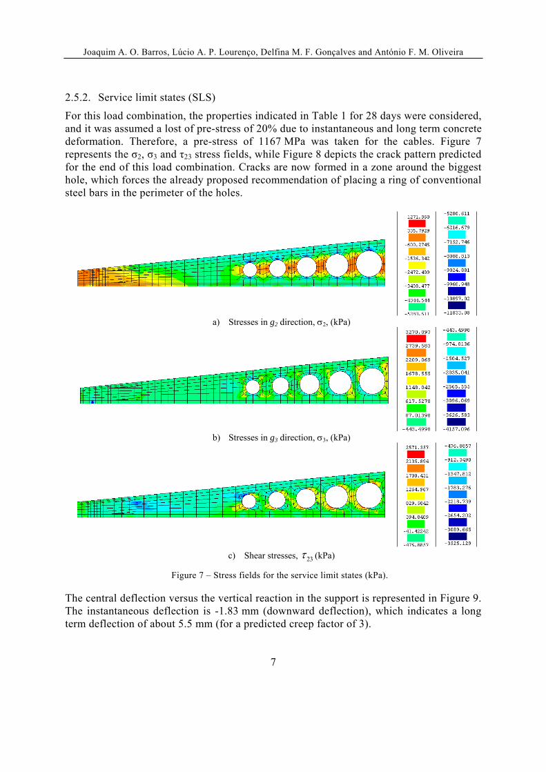
2.5.2. Service limit states (SLS)
For this load combination, the properties indicated in Table 1 for 28 days were considered, and it was assumed a lost of pre-stress of 20% due to instantaneous and long term concrete deformation. Therefore, a pre-stress of 1167 MPa was taken for the cables. Figure 7 represents the σ2, σ3 and τ23 stress fields, while Figure 8 depicts the crack pattern predicted for the end of this load combination. Cracks are now formed in a zone around the biggest hole, which forces the already proposed recommendation of placing a ring of conventional steel bars in the perimeter of the holes.
a) Stresses in g2 direction, 2, (kPa)
b) Stresses in g3 direction, 3, (kPa)
c) Shear stresses, 23 (kPa)
Figure 7 – Stress fields for the service limit states (kPa).
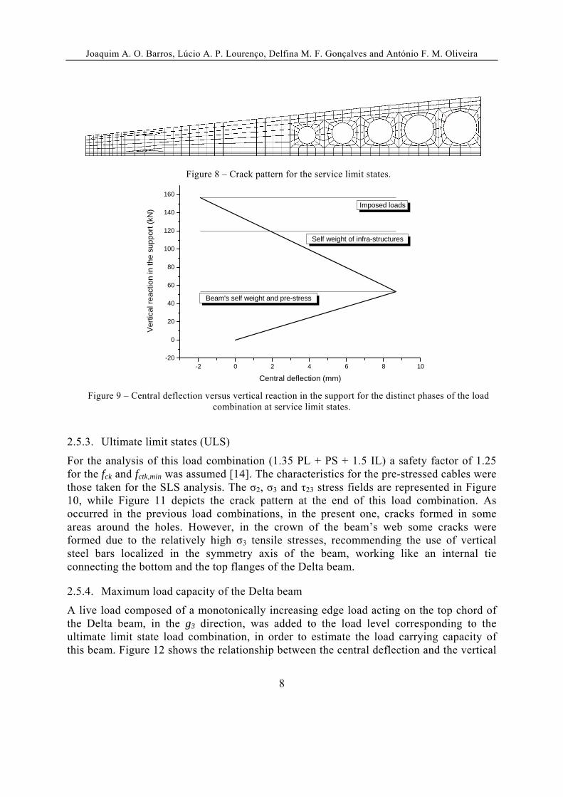
The central deflection versus the vertical reaction in the support is represented in Figure 9. The instantaneous deflection is -1.83 mm (downward deflection), which indicates a long term deflection of about 5.5 mm (for a predicted creep factor of 3).
Joaquim A. O. Barros, Lúcio A. P. Lourenço, Delfina M. F. Gonçalves and António F. M. Oliveira
8
Figure 8 – Crack pattern for the service limit states.
-2 0 2 4 6 8 10-20
0
20
40
60
80
100
120
140
160
Imposed loads
Self weight of infra-structures
Ver
tical
rea
ctio
n in
the
supp
ort (
kN)
Central deflection (mm)
Beam's self weight and pre-stress
Figure 9 – Central deflection versus vertical reaction in the support for the distinct phases of the load combination at service limit states.
2.5.3. Ultimate limit states (ULS)
For the analysis of this load combination (1.35 PL + PS + 1.5 IL) a safety factor of 1.25 for the fck and fctk,min was assumed [14]. The characteristics for the pre-stressed cables were those taken for the SLS analysis. The σ2, σ3 and τ23 stress fields are represented in Figure 10, while Figure 11 depicts the crack pattern at the end of this load combination. As occurred in the previous load combinations, in the present one, cracks formed in some areas around the holes. However, in the crown of the beam’s web some cracks were formed due to the relatively high σ3 tensile stresses, recommending the use of vertical steel bars localized in the symmetry axis of the beam, working like an internal tie connecting the bottom and the top flanges of the Delta beam.
2.5.4. Maximum load capacity of the Delta beam
A live load composed of a monotonically increasing edge load acting on the top chord of the Delta beam, in the g3 direction, was added to the load level corresponding to the ultimate limit state load combination, in order to estimate the load carrying capacity of this beam. Figure 12 shows the relationship between the central deflection and the vertical

Joaquim A. O. Barros, Lúcio A. P. Lourenço, Delfina M. F. Gonçalves and António F. M. Oliveira
9
reaction at the support for the Delta beam. The analysis was interrupted when the central deflection exceeded 80 mm.
a) Stresses in g2 direction, 2, (kPa)
b) Stresses in g3 direction, 3, (kPa)
c) Shear stresses, 23 (kPa)
Figure 10 – Stress fields for the ultimate limit states (kPa).
Figure 11 – Crack pattern for the ultimate limit states.
From this graph it is apparent that above the load corresponding to the ultimate limit state, the beam entered in a pronounced nonlinear phase, with a formation of a diffuse crack pattern in the bottom flange of the beam, in the beam’s web between the thicker cross section and the first hole, and in the perimeter of the holes (Figure 13).

Joaquim A. O. Barros, Lúcio A. P. Lourenço, Delfina M. F. Gonçalves and António F. M. Oliveira
10
-100 -80 -60 -40 -20 0 20
0
100
200
300
400
Imposed loads
Self weight of infra-structures
Ver
tical
re
actio
n in
the
sup
por
t (kN
)
Central deflection (mm)
Beam's self weight and pre-stress
Figure 12 – Central deflection versus vertical reaction.
Figure 13 – Crack pattern for a vertical reaction in the support of 400 kN – (red: crack in opening process; green: crack in closing process; blue: cracks in reopening process)
Table 4 resumes the obtained results. The obtained maximum and code-allowed crack openings are indicated in Table 5. The maximum crack opening was estimated multiplying
the maximum crack strain normal to the crack ( ,maxcrn ) to the crack band width of the
integration point where this ,maxcrn occurred. From the values of Table 5 it can be concluded
that, even for the maximum attained load applied to the beam, the maximum crack width did not exceed the allowed crack opening limit.
σ2
(MPa) σ3
(MPa) τ23
(MPa) Minimum Maximum Minimum Maximum
Production -17.10 1.25 -3.52 1.84 -2.99 a 3.33
SLS -11.83 1.271 -4.16 3.27 -3.53 a 2.57
ULS -14.30 2.24 -5.73 2.92 -4.06 a 3.32
Table 4 – Main results (negative values: compression).

Joaquim A. O. Barros, Lúcio A. P. Lourenço, Delfina M. F. Gonçalves and António F. M. Oliveira
11
Crack opening (mm)
Predicted Code-allowed
Production 0.007 Pre-stressed cables w=0.1 mm
Passive reinforcement
w=0.2 mm
SLS 0.001
ELU 0.010
Table 5 – Crack opening.
3. BEAM-COLUMN CONNEXION
The beam-column connexion is assured by threaded steel rods of 25 mm diameter, as schematically represented in Figure 14.
A
A
AA
Steel rods
Figure 14 – Connexion mechanism of the Beam-Column.
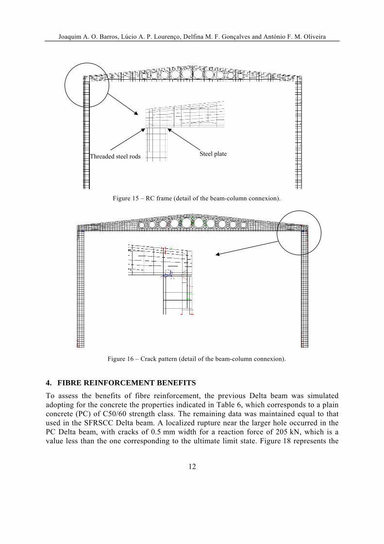
In order to assess the influence of this connexion in terms of the maximum tensile stresses in the beam of a representative RC frame of an industrial building, the frame was simulated numerically with the crack constitutive model used for the analysis of the Delta beam. The columns were discretized with 8 nodes quadrilateral finite plane stress state elements, and the connecting threaded steel rods were discretized with 2D embedded elements (perfectly bond was assumed). A steel plate, placed in between the interior contact beam-column, was simulated by a fictitious material of infinite strength in compression and null strength in tension in order to allow the transference of compressive forces only (Figure 15). The partial beam-column continuity provided by the threaded steel rods decreased the maximum tensile stresses in the beam, but cracks were formed in the top of the Delta beam in the supporting zone (Figure 16). Therefore, conventional steel bars should be applied in these zones to avoid the formation of these cracks. To avoid the formation of unstable cracks in the crack critical zones the arrangement of passive steel reinforcement represented in Figure 17 is recommended for the SFRSCC Delta beams.
Joaquim A. O. Barros, Lúcio A. P. Lourenço, Delfina M. F. Gonçalves and António F. M. Oliveira
12
Figure 15 – RC frame (detail of the beam-column connexion).
Figure 16 – Crack pattern (detail of the beam-column connexion).
4. FIBRE REINFORCEMENT BENEFITS
To assess the benefits of fibre reinforcement, the previous Delta beam was simulated adopting for the concrete the properties indicated in Table 6, which corresponds to a plain concrete (PC) of C50/60 strength class. The remaining data was maintained equal to that used in the SFRSCC Delta beam. A localized rupture near the larger hole occurred in the PC Delta beam, with cracks of 0.5 mm width for a reaction force of 205 kN, which is a value less than the one corresponding to the ultimate limit state. Figure 18 represents the
Threaded steel rods Steel plate

Joaquim A. O. Barros, Lúcio A. P. Lourenço, Delfina M. F. Gonçalves and António F. M. Oliveira
13
deformed mesh and the crack pattern of the mentioned failure zone (the cracks of pink colour are completely open, i.e., the fracture energy was already exhausted). Therefore, due to the resistance offered by fibres crossing the micro and meso-cracks, a localized failure did not occur in SFRSCC Delta beam up to very high deflection level, having been formed a diffuse crack pattern with clear benefits in terms of load carrying capacity, material durability and structural integrity.
A
A
B
B
C
C
D
D
A-A
Pre-stressed cables
Conventional reinforcement
B-B C-C D-D
Conventional reinforcement
ConventionalReinforcement
+
Figure 17 – Recommended reinforcement for the SFRSCC Delta beams
t E (GPa)
ckf
(MPa) ,minctkf
(MPa) FG
(N/mm)
,2
,
crn
crn u
,2
,1
crn
crn
,3
,
crn
crn u
,3
,1
crn
crn
28 days 39.0 50.0 2.90 0.1 0.05 0.60 0.20 0.20
Table 6 – Properties of plain concrete (C50/60).
Figure 18 – Deformed mesh (a) and crack pattern in the critical zone of the pre-stressed PC Delta beam (b). (cracks with pink colour: completely open)

Joaquim A. O. Barros, Lúcio A. P. Lourenço, Delfina M. F. Gonçalves and António F. M. Oliveira
14
5. POSSIBLE ENHANCEMENTS
Due to the distribution of principal stresses in the SFRSCC Delta beam, elliptical holes of a variable inclination of its larger axis (Figure 19) provide better structural behaviour than circular holes, as Figure 20 shows.
Figure 19 – Half beam of pre-stressed SFRSCC Delta beam with elliptical holes.
-100 -80 -60 -40 -20 0 20
0
100
200
300
400
500
Ve
rtic
al r
ea
ctio
n in
the
su
pp
ort
(kN
)
Beam's self weight and pre-stress
Self weight of infra-structures
Imposed loads
Central deflection (mm)
Circular Holes Elliptical Holes
Figure 20 – Central deflection versus vertical reaction of SFRSCC beams with circular and elliptical
holes.
6. CONCLUSIONS
In this paper the use of fibre reinforced concrete (FRC) and advanced numerical models, able of simulating the crack initiation and crack propagation in cement based materials, were used to explore the possibility of enhancing the structural behaviour of precast structural elements for industrial buildings. The study was focalized in pre-stress Delta beams, having been demonstrated that fibre reinforcement can almost totally replace stirrups and passive longitudinal reinforcement. These types of conventional reinforcements need to be used only in critical zones that the study has determined. A

Joaquim A. O. Barros, Lúcio A. P. Lourenço, Delfina M. F. Gonçalves and António F. M. Oliveira
15
connexion between Delta beam and RC columns was studied in order to decrease the tensile stresses in the beam and to decrease the buckling length of the column, with evident benefits in terms of the costs of the columns.
7. AKNOWLEDGEMENTS
The authors wish to acknowledge the support provided by “Mota-Engil, Betão e pré-fabricados, Lda” and “CIVITEST – Pesquisa de Novos Materiais para a Engenharia Civil” Companies.
REFERENCES
[1] Santos, P.F.S.; Barros, J.A.O.; Lourenço, L.A.P., “Steel fibres for the shear resistance of high strength concrete beams”, BEFIB 2008, 7th RILEM International Symposium on Fibre Reinforced Concrete Design and Applications, Paper SIM01, 17-19 September, (2008).
[2] Maekawa, K.; Ishida, T.; Kishi, T., “Multi-scale modelling of structural concrete”, Edit. Taylor & Francis, 645 pgs., (2009).
[3] Sena-Cruz, J.M.; Barros, J.A.O.; Azevedo, A.F.M.; Ventura Gouveia, A.V. “Numerical simulation of the nonlinear behavior of RC beams strengthened with NSM CFRP strips“,CMNE 2007 - Congress on Numerical Methods in Engineering and XXVIII CILAMCE - Iberian Latin American Congress on Computational Methods in Engineering, Abstract pp. 289, Paper nº 485 published in CD – FEUP, 20 pp., Porto, 13-15 June (2007).
[4] Barros, J.A.O., “Steel fiber reinforced self-compacting concrete – from the material characterization to the structural analysis”, HAC2008, 1st Spanish Congress on Self-Compacting Concrete, Valencia, Spain, 31-58, 18-19 February, (2008). (keynote lecturer)
[5] Pereira, E.B.; Barros, J.A.O., Camões, A.F.F.L., “Steel fiber reinforced self-compacting concrete – experimental research and numerical simulation”, Journal of Structural Engineering, 134(8), 1310-1321, August (2008).
[6] Barros, J.A.O.; Pereira, E.B.; Santos, S.P.F., “Lightweight panels of steel fiber reinforced self-compacting concrete”, Journal of Materials in Civil Engineering, 19(4), 295-304, (2007).
[7] CEB-FIB (1993). “CEB-FIP Model Code 1990 - Design Code.” Thomas Telford, Lausanne, Switzerland, (1993).
[8] Sena-Cruz, J.M. “Strengthening of concrete structures with near-surface mounted CFRP laminate strips.” PhD Thesis, Department of Civil Engineering, University of Minho, (2004). <http://www.civil.uminho.pt/composites/Publications/2006/JA2006_004_JCCC.pdf>
[9] Bazant, Z.P.; Oh, B.H., “Crack band theory for fracture of concrete”, Materials and Structures, RILEM, 16(93), 155-177, (1983).
[10] EN 1991-1-1, Eurocode 1: Actions on structures . Part 1-1 : General actions – Densities, self-weight, imposed loads for buildings, April (2002)
[11] EN 1991-1-3, Eurocode 1: Actions on structures . Part 1-3 : General actions – Snow loads, July (2003)
[12] EN 1991-1-4, Eurocode 1: Actions on structures . Part 1-4 : General actions – Wind loads, April (2005)
[13] EN 1998-1, Eurocode 8: Design of structures for earthquake resistance – Part 1 : General rules,seismic actions and rules for buildings, December (2004)
[14] CNR, “Istruzioniper la Progettazione, l’Esecuzione ed il Controllodi Strutture di Calcestruzzo Fibrorinforzato”, (2006).