Innovative Solutions for Minimizing Differential Deflection and Heaving Motion in Very Large...
212
INNOVATIVE SOLUTIONS FOR MINIMIZING DIFFERENTIAL DEFLECTION AND HEAVING MOTION IN VERY LARGE FLOATING STRUCTURES PHAM DUC CHUYEN NATIONAL UNIVERSITY OF SINGAPORE 2009
-
Upload
salimahsabri -
Category
Documents
-
view
90 -
download
6
Transcript of Innovative Solutions for Minimizing Differential Deflection and Heaving Motion in Very Large...

INNOVATIVE SOLUTIONS FOR MINIMIZING
DIFFERENTIAL DEFLECTION AND HEAVING MOTION
IN VERY LARGE FLOATING STRUCTURES
PHAM DUC CHUYEN
NATIONAL UNIVERSITY OF SINGAPORE
2009

INNOVATIVE SOLUTIONS FOR MINIMIZING
DIFFERENTIAL DEFLECTION AND HEAVING MOTION
IN VERY LARGE FLOATING STRUCTURES
PHAM DUC CHUYEN
B.Eng. (NUCE), M.Eng. (AIT)
A THESIS SUBMITTED
FOR THE DEGREE OF DOCTOR OF PHILOSOPHY
DEPARTMENT OF CIVIL ENGINEERING
NATIONAL UNIVERSITY OF SINGAPORE
2009

Acknowledgements
i
ACKNOWLEDGMENTS
First of all, my greatest thanks go to my supervisor Professor Wang Chien Ming, for
his education, ideas, inspiration, advises, prompt and clear comments about our work,
answers on many questions, and constant enthusiasm and interest. I consider myself as
a very happy person to work with such an outstanding researcher as a supervisor. And
I learned a lot about research, scientific philosophy and other things, for instance, how
to get joy from the equations and problems.
Next, I am grateful to my co-supervisor Professor Ang Kok Keng for his
valuable and useful discussions, information and comments through out the research. I
am also indeed grateful to Professor Tomoaki Utsunomiya from Kyoto University for
his advice and useful discussions on this research study.
I would also like to thank the chairman of my thesis advisory committee,
Professor Koh Chan Ghee for his valuable advice and suggestions on my research and
thesis. I am also thankful for the professors who examined my thesis. Their supportive
comments and suggestions were very much useful for the future improvement of the
thesis.
I’m grateful to the National University of Singapore for providing financial
support in the form of the NUS scholarship and facilities to carry out the research. The

Acknowledgements
ii
support provided by Mr. Krishna Sanmugam and technicians at Hydraulic Laboratory
in the use of equipments and computer facilities to carry out the experiment is also
appreciated.
In addition, I would like to extend my gratefulness to my colleagues in Civil
Engineering Department, especially Mr Tay Zhi Yung, Mr Muhammad Riyansyah, Ms
Bangun Emma Patricia, for their friendship, encouragement and valuable discussion
during the study.
Last but not least, I would like to express the deepest gratitude to my beloved
parents, wife and sisters for their eternal support, encouragement and love. I could not
finish the whole study without the great love and care from you.

iii
TABLE OF CONTENTS
Acknowledgements i
Table of Contents iii
Summary viii
List of Tables xi
List of Figures xii
Notations xix
Chapter 1 Introduction 1
1.1 Background information on VLFS 3
1.1.1 Types of VLFS 3
1.1.2 Advantages of VLFS 4
1.1.3 Applications of VLFS 5
1.1.4 VLFS components 12
1.2 Literature Survey 12
1.2.1 VLFS assumptions, shapes and models 13
1.2.2 VLFS and water interaction modeling 15
1.2.3 Minimizing differential deflection in VLFS 17
1.2.4 Minimizing motion in VLFS 18
1.3 Objectives and scope of study 21
1.4 Layout of thesis 22
Table of Contents
iv
Chapter 2 Minimizing Differential Deflection in Circular VLFS 25
2.1 Introduction 25
2.2 Problem definition 27
2.3 Basic assumptions and governing equations 29
2.4 Exact bending solutions and boundary conditions 31
2.4.1 VLFS regions without buoyancy force 31
2.4.2 VLFS regions with buoyancy force 32
2.4.3 Boundary and continuity conditions 33
2.5 Results and discussions on effectiveness of gill cells 34
2.5.1 Basic dimensions and properties of VLFS example, loading and
freeboard conditions 34
2.5.2 Verification of results of VLFS with gill cells 34
2.5.3 Effectiveness of gill cells in reducing the differential deflection and
stress-resultants 36
2.6 Optimal design/location of gill cells in circular VLFS 40
2.6.1 Case 1 – Varying loading magnitudes ql 41
2.6.2 Case 2 – Varying loading radius r0 43
2.6.3 Case 3 – Varying top and bottom plate thicknesses t 45
2.6.4 Case 1 – Varying freeboard hf 47
2.7 Comparing the effectiveness of gill cells with stepped VLFS 48
2.7.1 Case 1 – Varying loading magnitudes ql 49
2.7.2 Case 2 – Varying loading radius r0 50
2.7.3 Case 3 – Varying top and bottom plate thicknesses t 51
2.8 Optimal design/location of gill cells in annular VLFS 52

Table of Contents
v
2.8.1 Dimensions, properties of annual VLFS and proposed gill cells
location 52
2.8.2 Optimization formulation 53
2.8.3 Optimization results 54
2.9 Concluding remarks 56
Chapter 3 Minimizing Differential Deflection in Non-circular Shaped VLFS
Using Gill Cells 58
3.1 Introduction 58
3.2 Problem definition 59
3.3 Basic assumptions and FEM model for VLFS bending analysis 61
3.4 Results and discussions on effectiveness of gill cells 64
3.4.1 Dimensions and properties of VLFS examples, loading and freeboard
conditions 64
3.4.2 Verification of results 64
3.4.3 Effect of gill cells in reducing the differential deflection and von Mises
stress 65
3.5 Optimization problem 67
3.6 Optimization results 72
3.6.1 Optimization results for square VLFS 72
3.6.2 Optimization results for rectangular VLFS 78
3.6.3 Optimization results for I-shaped VLFS 84
3.7 Concluding remarks 90
Table of Contents
vi
Chapter 4 Minimizing Heaving Motion of Circular VLFS using Submerged
Plate 91
4.1 Introduction 91
4.2 Problem definition 92
4.3 Basic assumptions, equations and boundary conditions for circular VLFS 93
4.4 Model expansion of motion 96
4.5 Solution for radiation potentials 99
4.6 Solution for diffraction potentials 113
4.7 Equation of motion in modal coordinate 114
4.8 Results and discussions 117
4.9 Concluding remarks 128
Chapter 5 Minimizing Heaving Motion of Longish VLFS Using Anti-Heaving
Devices 130
5.1 Introduction 130
5.2 Experimental facility and instrumentation 133
5.2.1 Wave tank 133
5.2.2 Wave generating system 135
5.2.3 Data acquisition system 135
5.2.4 Testing condition 138
5.2.5 VLFS model 138
5.2.6 Types of anti-heaving devices 140
5.3 Experimental procedure 142
5.4 Experimental results 143
5.4.1 VLFS with submerged horizontal plate 143
5.4.2 VLFS with vertical plate 147

Table of Contents
vii
5.4.3 VLFS with L-shaped plate 151
5.4.4 VLFS with inclined plate 155
5.5 Most effective anti-heaving device 158
5.6 Concluding remarks 165
Chapter 6 Conclusions and Recommendations for Future Work 167
6.1 Conclusions 168
6.2 Recommendations for future work 171
References 174
List of Publications 186
viii
SUMMARY
In the new millennium, the world is facing new problems such as the lack of land, due
to the growing population and fast urban developments. Many island countries and
countries with long coastline have applied the traditional land reclamation method to
create land from the sea in order to decrease the pressure on the heavily used land
space. In recent years, an attractive alternative to land reclamation has emerged – the
very large floating structures technology. Very large floating structures (VLFS) can
and are already being used for storage facilities, industrial space, bridges, ferry piers,
docks, rescue bases, airports, entertainment facilities, military purpose, and even
habitation. VLFSs can be speedily constructed, exploited, and easily relocated,
expanded, or removed. These structures are reliable, cost effective, and
environmentally friendly.
VLFS may undergo large differential deflection under heavy nonuniformly
distributed loads and large motion under strong wave action. These conditions may
affect the smooth operation of equipments, the structural integrity and even the safety
of people on VLFS. The main objectives of this study are to develop (1) innovative
solutions to minimize the differential deflection of VLFS and (2) innovative solutions
to minimize the heaving motion of VLFSs for various shapes and dimensions. Various
alternative solutions are treated.
For minimizing the differential deflection in unevenly loaded circular VLFS,
two solutions were proposed. One solution makes use of the so-called “gill cells” and
Summary
ix
the other solution involves stepped VLFS (i.e. VLFS with varying height). Gill cells
are compartments in VLFS with holes or slits at their bottom floor that allow water to
flow in and out freely. As a result, the buoyancy forces are eliminated at the VLFS
region with gill cells. By suitable positioning the gill cells, one can reduce the
differential deflection of VLFS significantly. Although the stepped VLFS solution
reduces the differential deflection, it is not as effective as using the gill cells.
Furthermore, by reducing the differential deflection, the stress-resultants and bending
stresses in the VLFS are correspondingly reduced. In this study, the gill cells have
been used to minimize the slope in an annular shaped VLFS. In the circular and
annular shaped VLFS, the analytical bending solutions based on the Kirchhoff
hypothesis for plate bending analysis and the classical Newton optimization method
were used to seek the optimal design of gill cells.
Further investigation on the use of gill cells for minimizing the differential
deflection of arbitrary non-circular VLFS were made. As analytical solutions for
bending analysis of arbitrarily shaped VLFS are not available, finite plate element
analysis based on the Mindlin plate theory was employed. The Mindlin plate theory
was adopted in order to provide better accuracy of the computed stress resultants as
well as to include the effect of transverse shear deformation. For the optimization of
the position of gill cells in an arbitrarily shaped VLFS under an arbitrary loading
condition, Genetic Algorithms were employed because of its robustness in getting the
global optimum solution and the method allows the natural switching on and off the
gill cells in the optimization search. The effective of gill cells in reducing differential
deflection and stress-resultants in VLFS was confirmed from the extensive numerical
computations and examples considered.

Summary
x
In the investigation of the second topic of this study, i.e. the development of
anti-motion devices for VLFS under wave action, the author first considers circular
VLFS attached with a submerged horizontal annular plate strip that goes around the
edge of VLFS. Exact analytical solutions of hydroelastic were derived by making use
of the exact circular and annular plate solutions and exact velocity potential solutions
for circular domains. The effectiveness of this anti-motion device is demonstrated by
performing the analysis and comparing the results with and without the submerged
annular plate strip.
Further studies were investigated on minimizing the heaving motion of
rectangular VLFS under the action of waves by using various anti-motion devices
attached to its fore-end. These anti-motion devices include submerged horizontal plate,
vertical plate, L-shaped plate, and inclined plate. The effectiveness of these anti-
motion devices is confirmed by experimental results. Among these devices, inclined
plate seems to be the most effective device and it is recommended to be used in
appropriate VLFS applications.

xi
LIST OF TABLES
Table 2.1 Effect of gill cells in reducing maximum differential deflection and maximum stress-resultants 40 Table 2.2 Effectiveness of optimal gill cells in reducing the maximum slope and maximum stresses-resultants 55
Table 5.1 Pertinent information of model 140
Table 5.2 Anti-heaving devices considered in the experiment 141

xii
LIST OF FIGURES
Fig. 1.1 Types of VLFS 3
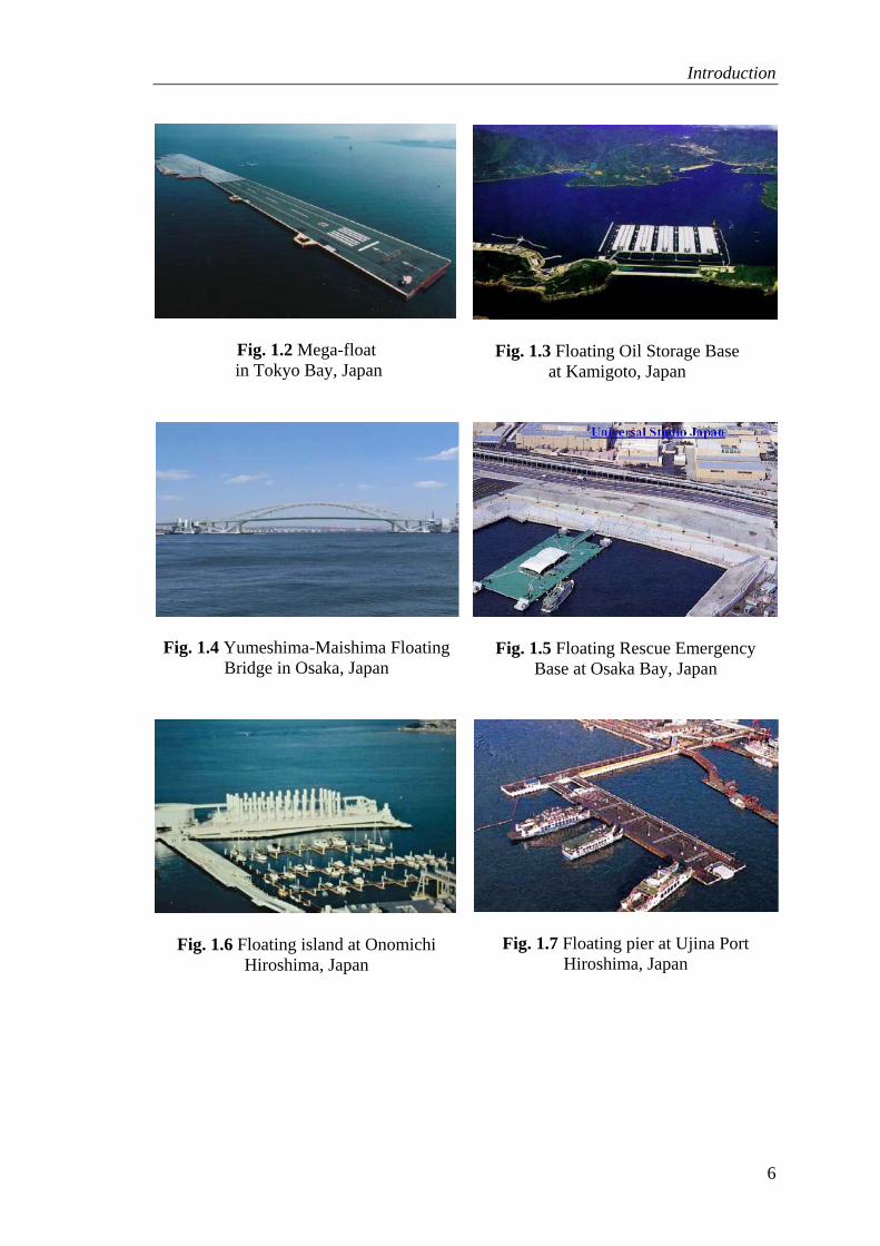
Fig. 1.2 Mega-float in Tokyo Bay, Japan 6
Fig. 1.3 Floating Oil Storage Base at Kamigoto, Japan 6
Fig. 1.4 Yumeshima-Maishima Floating Bridge in Osaka, Japan 6
Fig. 1.5 Floating Rescue Emergency Base at Osaka Bay, Japan 6
Fig. 1.6 Floating island at Onomichi Hiroshima, Japan 6
Fig. 1.7 Floating pier at Ujina Port Hiroshima, Japan 6
Fig. 1.8 Floating Restaurant in Yokohoma, Japan 7
Fig. 1.9 Floating Performance Stage, Singapore 7
Fig. 1.10 Floating helicopter pad in Vancouver, Canada 7
Fig. 1.11 Kelowna floating bridge in British Columbia, Canada 7
Fig. 1.12 Bergsøysund floating bridge, Norway 7
Fig. 1.13 Nordhordland Bridge Floating Bridge, Norway 7
Fig. 1.14 Hood Canal Floating Bridge in Washington States, USA 8
Fig. 1.15 Dubai Floating Bridge in Dubai, United Arab Emirates 8
Fig. 1.16 Marine Uranus by Nishimatsu Corporation 11
Fig. 1.17 Pearl Shell by Shimizu Corporation 11
Fig. 1.18 Osaka Focus A by Japanese Society of Steel Construction 11
Fig. 1.19 Osaka Focus B by Japanese Society of Steel Construction 11
List of Figures
xiii
Fig. 1.20 Components of a pontoon-type VLFS 12
Fig. 2.1 Pontoon-type circular VLFS with gill cells and varying heights 28
Fig. 2.2 Pontoon-type ring-shaped VLFS 29
Fig. 2.3 Design mesh of circular VLFS with gill cells used in SAP2000 analysis 35
Fig. 2.4 Comparison deflections w between analytical solutions and SAP2000 result of circular VLFS with gill cells 36 Fig. 2.5 Effect of gill cells on deflections w 38
Fig. 2.6 Effect of gill cells on shear force rQ 38
Fig. 2.7 Effect of gill cells on radial moment rM 39
Fig. 2.8 Effect of gill cells on circumferential moment θM 39
Fig. 2.9 Optimal design of gill cells when varying ql 42
Fig. 2.10 Effect of optimal gill cells when varying ql 42
Fig. 2.11 Optimal design of gill cells when varying r0 44
Fig. 2.12 Effect of optimal gill cells when varying r0 45
Fig. 2.13 Optimal design of gill cells when varying t 46
Fig. 2.14 Effect of optimal gill cells when varying t 46
Fig. 2.15 Optimal design of gill cells when varying freeboard hf 47
Fig. 2.16 Effect of optimal gill cells when varying freeboard hf 48
Fig. 2.17 Effect of optimal gill cells and optimal stepped VLFS when varying ql 50
Fig. 2.18 Effect of optimal gill cells and optimal stepped VLFS when varying r0 51
Fig. 2.19 Effect of optimal gill cells and optimal stepped VLFS when varying t 52
Fig. 2.20 Annular VLFS with gill cells 53
Fig. 2.21 Effect of optimal gill cells on slope dw 55
Fig. 3.1 Square, rectangular and I-shaped VLFSs 60

List of Figures
xiv
Fig. 3.2 Definitions of deflection and rotations 62
Fig. 3.3 Nondimensionalized deflection contour w in a quarter of the square VLFS without gill cells 66 Fig. 3.4 Nondimensionalized deflection contour w in a quarter of the square VLFS with gill cells 67 Fig. 3.5 Transformation of binary string to a quarter of the square VLFS with gill cells (shaded cells) in genetic algorithms rubric 70 Fig. 3.6 Optimization program flow-chart integrating GA and developed FEM model 72 Fig. 3.7 Stage 1 for a quarter of square VLFS 73
Fig. 3.8 Layouts of gill cells in quadrant of square VLFS for various generations in Stage 2 74 Fig. 3.9 Square VLFS with some possible optimal designs of gill cells 75
Fig. 3.10 Nondimensionalized deflection contour w of square VLFS 76
Fig. 3.11 Von Mises stress of a quarter of square VLFS 77
Fig. 3.12 Stage 1 for rectangular VLFS 79
Fig. 3.13 Layouts of gill cells in a quadrant of rectangular VLFS for various generations in Stage 2 79 Fig. 3.14 Rectangular VLFS with some possible optimal designs of gill cells 81
Fig. 3.15 Nondimensionalized deflection contour w in the rectangular VLFS 82
Fig. 3.16 Von Mises stress of a quarter of rectangular VLFS 83
Fig. 3.17 Stage 1 for I-shaped VLFS 84
Fig. 3.18 Layouts of gill cells in quadrant of I-shaped VLFS for various generations in Stage 2 85 Fig. 3.19 I-shaped VLFS with some possible optimal designs of gill cells 87
Fig. 3.20 Nondimesionalized deflection contour w in I-shaped VLFS 88
Fig. 3.21 Von Mises stress of a quarter of the I-shaped VLFS 89
Fig. 4.1 Geometry of uniform circular VLFS and coordinate system 93

List of Figures
xv
Fig. 4.2 Nondimensionalized deflection amplitude for circular VLFS with 2m width submerged plate 119 Fig. 4.3 Nondimensionalized deflection amplitude for circular VLFS with 10m width submerged plate 119 Fig. 4.4 Nondimensionalized deflection amplitude of VLFS without and with submerged plate of various widths 120 Fig. 4.5 Nondimensionalized bending moment amplitude of VLFS without and with submerged plate of various widths 120 Fig. 4.6 Nondimensionalized twisting moment amplitude of VLFS without and with submerged plate of various widths 121 Fig. 4.7 Nondimensionalized transverse shear force amplitude of VLFS without and with submerged plate of various widths 121 Fig. 4.8 Nondimensionalized deflection amplitude for circular VLFS with 8m width submerged plate at level d = 2m 123 Fig. 4.9 Nondimensionalized deflection amplitude for circular VLFS with 8m width submerged plate at level d = 19.5m 123 Fig. 4.10 Nondimensionalized deflection amplitude of VLFS without and with submerged plate at various depths 124 Fig. 4.11 Nondimensionalized bending moment amplitude of VLFS without and with submerged plate at various depths 124 Fig. 4.12 Nondimensionalized twisting moment amplitude of VLFS without and with submerged plate at various depths 125 Fig. 4.13 Nondimensionalized shear force amplitude of VLFS without and with submerged plate at various depths 125 Fig. 4.14 Nondimensionalized deflection amplitude for basic circular VLFS at fore-end 126 Fig. 4.15 Nondimensionalized deflection amplitude for circular VLFS with submerged plate at fore-end 127 Fig. 4.16 Nondimensionalized deflection amplitude of VLFS at fore-end 127
Fig. 4.17 Nondimensionalized deflection amplitude of VLFS at mid-position 128
Fig. 4.18 Nondimensionalized deflection amplitude of VLFS at back-end 128
Fig. 5.1 VLFS with box-shaped anti-motion device 130

List of Figures
xvi
Fig. 5.2 VLFS with submerged vertical plate anti-motion device 131
Fig. 5.3 VLFS with anti-motion devices treated by Ohta et al. (2002) 132
Fig. 5.4 Wave tank in Hydraulic Engineering Laboratory, NUS 133
Fig. 5.5 Experimental setup 134
Fig. 5.6 Wave generating system controller 136
Fig. 5.7 Wave data acquisition system 137
Fig. 5.8 Deflection data acquisition system 137
Fig. 5.9 Experimental model placed in wave tank 139
Fig. 5.10 Simple bending test to determine flexural rigidity EI of VLFS model 140
Fig. 5.11 Nondimensionalized deflection amplitude of VLFS without and with horizontal plate at wave period 0.8s 144 Fig. 5.12 Nondimensionalized deflection amplitude of VLFS without and with horizontal plate at wave period 0.9s 145 Fig. 5.13 Nondimensionalized deflection amplitude of VLFS without and with horizontal plate at wave period 1s 145 Fig. 5.14 Nondimensionalized deflection amplitude of VLFS without and with horizontal plate at wave period 1.1s 146 Fig. 5.15 Nondimensionalized deflection amplitude of VLFS without and with horizontal plate at wave period 1.2s 146 Fig. 5.16 Nondimensionalized deflection amplitude of VLFS without and with horizontal plate at wave period 1.3s 147 Fig. 5.17 Nondimensionalized deflection amplitude of VLFS without and with vertical plate at wave period 0.8s 148 Fig. 5.18 Nondimensionalized deflection amplitude of VLFS without and with vertical plate at wave period 0.9s 148 Fig. 5.19 Nondimensionalized deflection amplitude of VLFS without and with vertical plate at wave period 1s 149 Fig. 5.20 Nondimensionalized deflection amplitude of VLFS without and with vertical plate at wave period 1.1s 149 Fig. 5.21 Nondimensionalized deflection amplitude of VLFS without and with vertical plate at wave period 1.2s 150

List of Figures
xvii
Fig. 5.22 Nondimensionalized deflection amplitude of VLFS without and with vertical plate at wave period 1.3s 150 Fig. 5.23 Nondimensionalized deflection amplitude of VLFS without and with L-shaped plate at wave period 0.8s 152 Fig. 5.24 Nondimensionalized deflection amplitude of VLFS without and with L-shaped plate at wave period 0.9s 152 Fig. 5.25 Nondimensionalized deflection amplitude of VLFS without and with L-shaped plate at wave period 1s 153 Fig. 5.26 Nondimensionalized deflection amplitude of VLFS without and with L-shaped plate at wave period 1.1s 153 Fig. 5.27 Nondimensionalized deflection amplitude of VLFS without and with L-shaped plate at wave period 1.2s 154 Fig. 5.28 Nondimensionalized deflection amplitude of VLFS without and with L-shaped plate at wave period 1.3s 154 Fig. 5.29 Nondimensionalized deflection amplitude of VLFS without and with inclined plate at wave period 0.8s 155 Fig. 5.30 Nondimensionalized deflection amplitude of VLFS without and with inclined plate at wave period 0.9s 156 Fig. 5.31 Nondimensionalized deflection amplitude of VLFS without and with inclined plate at wave period 1s 156 Fig. 5.32 Nondimensionalized deflection amplitude of VLFS without and with inclined plate at wave period 1.1s 157 Fig. 5.33 Nondimensionalized deflection amplitude of VLFS without and with inclined plate at wave period 1.2s 157 Fig. 5.34 Nondimensionalized deflection amplitude of VLFS without and with inclined plate at wave period 1.3s 158 Fig. 5.35 Nondimensionalized deflection amplitude of VLFS without and with anti-heaving device of 20cm length at wave period 0.8s 159 Fig. 5.36 Nondimensionalized deflection amplitude of VLFS without and with anti-heaving device of 20cm length at wave period 0.9s 159 Fig. 5.37 Nondimensionalized deflection amplitude of VLFS without and with anti-heaving device of 20cm length at wave period 1s 160

List of Figures
xviii
Fig. 5.38 Nondimensionalized deflection amplitude of VLFS without and with anti-heaving device of 20cm length at wave period 1.1s 160 Fig. 5.39 Nondimensionalized deflection amplitude of VLFS without and with anti-heaving device of 20cm length at wave period 1.2s 161 Fig. 5.40 Nondimensionalized deflection amplitude of VLFS without and with anti-heaving device of 20cm length at wave period 1.3s 161 Fig. 5.41 Nondimensionalized deflection amplitude of VLFS without and with anti-heaving device of 10cm length at wave period 0.8s 162 Fig. 5.42 Nondimensionalized deflection amplitude of VLFS without and with anti-heaving device of 10cm length at wave period 0.9s 163 Fig. 5.43 Nondimensionalized deflection amplitude of VLFS without and with anti-heaving device of 10cm length at wave period 1s 163 Fig. 5.44 Nondimensionalized deflection amplitude of VLFS without and with anti-heaving device of 10cm length at wave period 1.1s 164 Fig. 5.45 Nondimensionalized deflection amplitude of VLFS without and with anti-heaving device of 10cm length at wave period 1.2s 164 Fig. 5.46 Nondimensionalized deflection amplitude of VLFS without and with anti-heaving device of 10cm length at wave period 1.3s 165

Notations
xix
NOTATIONS
A amplitude of incident wave (m)
a half width of annual submerged horizontal plate, length of cantilever test (m)
B horizontal dimension of anti-heaving device
b half length of VLFS testing model
Bχ curvature-displacement matrix
Bγ shear strain displacement matrix
D flexural rigidity of VLFS (kNm)
d distance from sea-bed to submerged horizontal plate (m)
Db bending stiffness matrix
DS shear stiffness matrix
dwdx
slope in annular VLFS
maxdwdx
maximum slope in annular VLFS with gill cells
0dwdx
maximum slope in annular VLFS without gill cells
E Young modulus of material (kN/m2)
Em equivalent Young modulus of VLFS (kN/m2)
Fi force matrix
G shear modulus (kN/m2)

Notations
xx
g gravitational acceleration (m/s2)
H water depth (m)
h overall depth of VLFS (m)
hf freeboard at the edge of VLFS (m)
h1 larger depth of stepped VLFS (m)
h2 smaller depth of stepped VLFS (m)
( )2 ( )nH • Hankel function of the second-kind
i imaginary unit i2 = -1
)(•nI modified first kind Bessel function
)(•nJ first kind Bessel function
K stiffness matrix
k wave number
6/5=sK shear correction factor for the Mindlin plate
( )nK • modified second-kind Bessel function
kw Winkler spring constant (kN/m3)
Mr radial bending moment (kNm)
Mθ twisting moment (kNm)
( )r rM M R D= non-dimensional bending moment
( )M M R Dθ θ= non-dimensional twisting moment
Mrmax maximum radial bending moment in VLFS with gill cells (kNm)
Mθmax maximum twisting moment in VLFS with gill cells (kNm)
Mr0 maximum radial bending moment in VLFS (kNm)
Mθ0 maximum twisting moment in VLFS (kNm)
Nw shape functions matrix

Notations
xxi
p total load acting on VLFS (kN/m2)
qs self weight of VLFS (kN/m2)
ql uniformly distributed loading magnitude acting on VLFS (kN/m2)
q0 basic loading magnitudes acting on VLFS (kN/m2)
Qr shear force (kN)
( )2r rQ Q R D= non-dimensional shear force
Qrmax maximum shear force in VLFS with gill cells (kN)
Qr0 maximum shear force in VLFS (kN)
R radius of circular VLFS, outer radius of annular VLFS (m)
r radial coordinate (m)
r0 loading radius of circular VLFS, inner radius of annular VLFS (m)
r1 inner radius of gill cells region in circular VLFS, inner radius of stepped region in circular VLFS, inner radius of the first gill cells region in annular VLFS (m) r2 outer radius of gill cells region in circular VLFS, outer radius of stepped region in circular VLFS, outer radius of the first gill cells region in annular VLFS (m) r3 inner radius of loading region in annular VLFS (m)
r4 outer radius of loading region in annular VLFS (m)
r5 inner radius of the second gill cells region in annular VLFS (m)
r6 outer radius of the second gill cells region in annular VLFS (m)
S non-dimensional plate rigidity
s number of sequence for each mode
t top and bottom plate thickness of VLFS (m)
t0 basic top and bottom plate thickness of VLFS (m)
w deflection of VLFS (m)
w displacement vector
we deflection at the edge of VLFS (m)

Notations
xxii
wc deflection at the center of VLFS (m)
wgm maximum deflection in gill cells region (m)
wma maximum deflection of VLFS (m)
wmi minimum deflection of VLFS (m)
/w w h= non-dimensional deflection
x horizontal coordinate (m)
( )nY • second kind Bessel function
z vertical coordinate (m)
2 1h hα = step ratio
Γ truncation number
γ shear strain vector
γm weight density of VLFS (kg/m3)
γw weight density of water (kg/m3)
wΔ maximum differential deflection in VLFS with gill cells or stepped VLFS (m)
0wΔ maximum differential deflection in VLFS (m)
( )∇ • Laplacian operator
ε curvature strain vector
θ circumferential coordinate (radian)
λ wave length (m)
njλ j -th positive root of the equation ( ) 0n njJ λ =
υ Poisson ratio
χ non-dimensional radial coordinate = r/R
φ velocity potential
nsφ radiation potential

Notations
xxiii
Dnφ diffraction potential
Iφ velocity potential of the undisturbed incident wave
xφ rotation about the y axe
yφ rotation about the x axe
ϖ wave frequency
1
CHAPTER 1
INTRODUCTION
The total land area of the Earth’s surface is about 148,300,000 square kilometers,
while the Earth’s surface area is 510,083,000 square kilometers. Thus, the main part of
the Earth’s surface is covered by sea, lakes, rivers, etc, which takes up 70 percent of
the Earth’s total surface area. Therefore, the land that we lived on forms only 30% of
the Earth’s surface. A large part of the Earth, which is the ocean, remains unexploited.
By the World Bank’s projection for global population, there will be 8.13 billion
people by 2030 and about 60% of this population will be living in urban areas. The
additional 2 billion people in a span of about 26 years will add tremendous pressure on
the land scarce cities. Thus in many island countries and countries with long coast
lines, the governments of these countries have resorted to land reclamation from the
sea in order to ease the expected pressure on the land space. There are, however,
constraints on land reclamation works such as the negative environmental impact on
the coastlines of the country and neighboring countries and marine ecological system,
as well as huge economic costs in reclaiming land from deep coastal water, especially
when the sand for reclamation has to be bought from other countries (Watanabe et al.
2004a).
In response to the aforementioned needs and problems, researchers and
engineers have proposed an interesting and attractive solution – the construction of
very large floating structures (VLFSs). In order to qualify for the VLFS status, Suzuki
and Yoshida (1996) proposed that the floating structure length to characteristic length

Introduction
2
(which is a function of the flexural rigidity to the buoyancy force) ratio and structural
length to wavelength ratio must be greater than unity. These two ratios imply a flexible
structure where the hydroelastic response dominates the rigid body responses under the
action of waves.
VLFS can be constructed to create floating airports, bridges, breakwaters, piers
and docks, storage facilities, wind and solar power plants, industrial space, emergency
bases, entertainment facilities, recreation parks, mobile offshore structures and even
for habitation. In certain applications of VLFS such as floating airports, floating
container terminals and floating dormitories where high loads are placed in certain
parts of the floating structure, the resulting differential deflections can be somewhat
large and may render certain equipment non operational. Therefore, it is important to
reduce the differential deflection in VLFS.
Generally, VLFS undergoes heaving, pitching and sway motion in the high seas.
Ohkusu and Nanba (1996) proposed an approach that treats the motion of VLFS as a
propagation of waves beneath a thin elastic-platform. Therefore, in order to reduce the
motion of VLFS, floating breakwaters as well as anti-motion devices on VLFS have
been proposed to reduce the wave transmitted under the VLFS. So far, there are many
research studies done on floating breakwaters. Recently, anti-motion devices have
been developed as alternatives for reducing the effect of waves on VLFS. An anti-
motion device is a body attached to an edge of VLFS so it does not need mooring
system like floating breakwaters and the time needed for construction is also shorter.
The rest of this chapter is organized as follows. Firstly, the background
information on VLFS is presented. A literature review then gives the information on
problems studied by researches and engineers, methods developed, and results derived

Introduction
3
about minimizing differential deflection and motion in VLFS. Finally, the objectives
and scope of study are given.
1.1 Background information on VLFS
1.1.1 Types of VLFS
VLFS may be classified under two broad categories (Watanabe et al. 2004a), namely
the pontoon-type and the semi-submersible type (Fig. 1.1). The latter type has a ballast
column tubes to raise the platform above the water level and suitable for use in open
seas where the wave heights are relatively large. VLFS of the semi-submersible type is
used for oil or gas exploration in sea and other purposes. It is kept in its location by
either tethers or thrusters. In contrast, the pontoon-type VLFS is a simple flat box
structure and features high stability, low manufacturing cost and easy maintenance and
repair. However, it is only suitable in calm sea waters, often near the shoreline.
Pontoon-type VLFS is also known in the literature as mat-like VLFS because of its
small draft in relation to the length dimensions. The Japanese refers to them as Mega-
Floats.
Pontoon-type
Semi-submersible-type
Fig. 1.1 Types of VLFS

Introduction
4
1.1.2 Advantages of VLFS
Very large floating structures have the following advantages over traditional
land reclamation in creating land from the sea:
• They are easy and fast to construct (components may be made at shipyards
and then be transported to and assembled at the site), thus, the sea space can
be quickly exploited.
• They are cost effective when the water depth is large or sea bed is soft.
• They are environmentally friendly as they do not damage the marine eco-
system or silt-up deep harbors or disrupt the ocean currents.
• They can easily be relocated (transported), removed, or expanded.
• The structures and people on VLFSs are protected from seismic shocks
since VLFSs are inherently base isolated.
• They do not suffer from differential settlement as in reclaimed soil
consolidation.
• Their positions with respect to the water surface are constant and thus
facilitate small boats and ship to come alongside when used as piers and
berths.
• Their location in coastal waters provide scenic body of water all around,
making them suitable for developments associated with leisure and water
sport activities.
• Their interior spaces may be used for car parks, offices, etc.
• There is no problem with rising sea level due to global warming.
Introduction
5
1.1.3 Applications of VLFS
Very large floating structures have already been used for different purposes in Japan,
Canada, Norway, USA, UK, Singapore, Brazil, and Saudi Arabia. China, Israel, the
Netherlands, Germany, and New Zealand are going to employ VLFSs in the near
future.
As the world’s leader in VLFSs, Japan constructed the Mega-Float in the
Tokyo Bay (Fig. 1.2), the floating oil storage base Shirashima and Kamigoto (Fig. 1.3),
the Yumeshima-Maishima Floating Bridge in Osaka (Fig. 1.4), the floating emergency
rescue bases in Tokyo Bay, Osaka Bay and Yokohama Bay (Fig. 1.5), the floating
island at Onomichi Hiroshima (Fig. 1.6), the floating ferry piers at Ujina Port
Hiroshima (Fig. 1.7) and the floating restaurant in Yokohoma (Fig. 1.8).
The world largest floating performance platform (Fig. 1.9) was built in
Singapore. Canada has a floating heliport pad in Vancouver (Fig. 1.10) and the
Kelowna floating bridge on Lake On in British Columbia (Fig. 1.11). Norway has the
Bergsøysund floating bridge (Fig. 1.12) and the Nordhordland bridge (Fig. 1.13). The
United States has the Hood Canal floating bridge in Washington State (Fig. 1.14).
Recently, in 2007, Dubai opened a 300m long floating concrete bridge over the Dubai
Creek (Fig. 1.15). The United Kingdom, Saudi Arabia, Brazil and other countries also
use floating structures for bridges, oil storage and other purposes.
Introduction
6
Fig. 1.2 Mega-float in Tokyo Bay, Japan
Fig. 1.3 Floating Oil Storage Base
at Kamigoto, Japan
Fig. 1.4 Yumeshima-Maishima Floating
Bridge in Osaka, Japan
Fig. 1.5 Floating Rescue Emergency
Base at Osaka Bay, Japan
Fig. 1.6 Floating island at Onomichi Hiroshima, Japan
Fig. 1.7 Floating pier at Ujina Port
Hiroshima, Japan

Introduction
7
Fig. 1.8 Floating Restaurant in Yokohoma, Japan
Fig. 1.9 Floating Performance Stage,
Singapore
Fig. 1.10 Floating helicopter pad
in Vancouver, Canada
Fig. 1.11 Kelowna floating bridge
in British Columbia, Canada
Fig. 1.12 Bergsøysund floating bridge,
Norway
Fig. 1.13 Nordhordland Bridge Floating
Bridge, Norway

Introduction
8
Fig. 1.14 Hood Canal Floating Bridge
in Washington States, USA Fig. 1.15 Dubai Floating Bridge in Dubai, United Arab Emirates
Source: Fig. 1.2 ~ 1.8 and 1.10 ~ 1.14 from Watanabe et al. (2004b), Fig. 1.15 from website: www.dubaiiformer.com
Pontoon floating bridge is the earliest application of the pontoon-type VLFS.
The first floating bridge is King Xerxes’ floating boat bridge across the Hellespont
(about 480 BC). Watanabe et al. (2004b) and Watanabe (2003) described the history
and worldwide development of floating bridges. The most famous floating bridges
constructed in the world are: the Galata Floating Bridge (1912) in Istanbul, the First
(1940), the Second (1963), and the Third Bridge (1989, Lacey Murrow), on Lake
Washington, and Hood Canal Bridge (1961) near Seattle in Washington state, the
Kelowna Floating Bridge (1958) in British Colombia, Canada, the Bergsøysund Bridge
(1992) and the Nordhordland Bridge (1994) over the deep fjords in Norway, a West
India Quay Footbridge in the Docklands, London (1996), the Admiral Clarey Bridge in
Hawaii (1998), Seebrücke (2000) in Saxony-Anhalt, Germany, a new swing floating
arch bridge Yumemai Bridge, in Osaka (2000), an pontoon bridges on the rivers
Amudarya and Syrdarya rivers in Uzbekistan and Turkmenistan (1989-2005). A
complete list of the pontoon bridges still in use and demolished can be found on the
website (http://en.structurae.de/structures/stype/index.cfm?ID=1051).
Large floating offshore structures can also be used for floating docks, piers and
container terminals. Many floating docks, piers, and berths are already in use all over

Introduction
9
the world. Floating piers have been constructed in Hiroshima, Japan, and Vancouver,
Canada. In Valdez, Alaska, a floating pier was designed for berthing the 50000-ton
container ships. The main advantage of a floating pier is its constant position with
respect to the waterline. Therefore, loading and unloading of cargo between the pier
and ship/ferry can operate smoothly. Floating docks have been constructed in the USA
and other countries. In case of rather deep water, VLFS are a good alternative to
traditional harbor facilities. Research on floating harbor facilities, their design and
analysis is going on in many countries (Watanabe et al. 2004a).
One more application of very large floating structures is the floating storage
facility. VLFSs have already been used for storing fuel. An offshore oil storage facility
is constructed like flat box-shaped tankers connected to each other and to other
components of the VLFS system. Japan has two major floating oil storage systems
(the only two in the world so far) namely Kamigoto (1990, near Nagasaki) and
Shirashima (1996, near Kitakyusyu) with capacity of 4.4 and 5.6 million kiloliters,
respectively. Complete information on the design, experiments and mooring of the oil
storage bases are given by Yoneyama et al. (2004).
VLFSs are ideal for applications as floating emergency rescue bases in seismic
prone areas owing to the fact that their bases are inherently isolated from seismic
motion. Japan has a number of such floating rescue bases parked in the Tokyo Bay, Ise
Bay and Osaka Bay. Specifications of the floating rescue bases can be found in
Yoneyama et al. (2004) and Watanabe et al. (2004b).
Another advantage of VLFS is its attractive panoramic view of the water body.
Waterfront properties and the sea appeal to the general public. Thus, VLFSs are
attractive for used as floating entertainment facilities such as hotels, restaurants,
shopping centers, amusement and recreation parks, exhibition centers, and theaters.

Introduction
10
Some floating entertainment facilities have been constructed. For example, the world
largest floating performer platform was built on the Marina Bay in Singapore in 2007
(Fig. 1.9), Aquapolis exhibition center in Okinawa (1975, already removed), the
Floating Island near Onomichi which resembles the Parthenon, and floating hotels in
British Columbia, Canada, and floating restaurants in Japan and Hong Kong.
In addition, VLFS can also be used as floating power plants. Floating power
plants for various types of energy are already being used in Brazil, Japan, Bangladesh,
Saudi Arabia, Argentina, and Jamaica. There are proposals to use VLFS for wind and
solar power plants (Takagi 2003 and Takagi and Noguchi 2005) and studies on this are
already underway. The Floating Structure Association of Japan has presented concept
designs of a clean power plant.
One of the most exciting applications of VLFS is the floating airport. The first
contemporary floating airport is constructed in 1943 by US Navy Civil Engineers
Corps by connecting pontoons. Recently, with the growth of cities and increase in air
traffic as well as the rise in land costs in major cities, city planners are considering the
possibility of using the coastal waters for urban developments including having
floating airports. Japan has made great progress by constructing a large airport in the
sea. Kansai International Airport (1994), Osaka, Japan, is the first airport in the world
completely constructed in the sea, although on an artificial reclaimed island. Airport
with runways on reclaimed islands in the sea are Chek Lap Kok International Airport
(1998), Hong Kong, China; Incheon International Airport (2001), Seoul, Korea;
Changi airport, Singapore; Central Japan International Airport, Nagoya; Kobe airport,
Japan. However, the extensive research on floating airports is continually pursued in
Japan (Tokyo, Osaka), USA (San Diego) and many other countries. The first largest
floating runway is the one-km long Mega-Float rest model built in 1998 in the Tokyo

Introduction
11
bay (Fig. 1.2). This is award of the Guinness book of records in 1999 for the world’s
largest man-made floating island. For small size, floating helicopter ports have already
been constructed in Vancouver, Canada (Fig. 1.9) and other places.
The final and the most advanced application of VLFS is the floating city. It
could become reality soon as various concepts have been proposed for building
floating cities or huge living complex. Figs. 1.16-1.19 show artist impressions of some
floating cities that have been proposed by various Japanese corporations.
Fig. 1.16 Marine Uranus by Nishimatsu Corporation
Fig. 1.17 Pearl Shell
by Shimizu Corporation
Fig. 1.18 Osaka Focus A by Japanese Society of Steel Construction
Fig. 1.19 Osaka Focus B by Japanese
Society of Steel Construction
Source: Fig. 1.16~1.19 from Watanabe et al. (2004b)

Introduction
12
1.1.4 VLFS components
The components of a VLFS system (general concept) are shown in Fig. 1.20. The
system comprises (1) a very large pontoon floating structure, (2) an access bridge or a
floating road to get to the floating structure from shore, (3) a mooring facility or station
keeping system to keep the floating structure in the specified place, and (4) a
breakwater, (usually needed if the significant wave height is greater than 4 m) which
can be floating as well, or anti-heaving device for reducing wave forces impacting the
floating structure, (5) structures, facilities and communications located on a VLFS.
Fig. 1.20 Components of a pontoon-type VLFS
1.2 Literature survey
This survey covers books, papers, reports and abstracts that give the basic theory for
reducing the differential deflection of VLFS under heavy load and reducing the motion
of VLFS under the action of wave. Different methods used for the problem are
described such as VLFS models and shapes, wave and other forces, anti-motion
devices. Also the author reviews what has been done already, what is currently being

Introduction
13
investigated and the future directions to study for the problem of reducing the
differential deflection and motion of VLFS.
Watanabe et al. (2004a and 2004b) presented very detailed surveys on the
research work on pontoon-type VLFSs. The numerous publications reported in
offshore structures/VLFS conference proceedings, journals, books and websites
confirm the interest in and importance of these structures to engineers and scientists.
Many papers on the analysis of VLFS were published in the following international
journals: Applied Ocean Research, Engineering Structures, International Journal of
Offshore and Polar Engineering, Journal of Engineering Mathematics, Journal of Fluid
Mechanics, Journal of Fluids and Structures, Marine Structures, Ocean Engineering,
Wave Motion; in the Proceedings of the International Workshops on Water Waves and
Floating Bodies (IWWWFB), International Offshore and Polar Engineering
Conference (ISOPE) and other conferences, workshops and seminars. Many
publications about VLFS have been published in non-scientific or scientific-popular
journals and newspapers and on the internet. Thus, the attention to and interest in the
problems of the behavior of floating plates in waves have recently increased.
1.2.1 VLFS assumptions, shapes and models
In this subsection, the author discusses the basic assumptions, the different shapes of
very large floating structures and their models proposed and analyzed by researchers
and engineers worldwide. In the hydroelastic analysis of VLFS, the basic assumptions
are usually made (Newman 1997, Stoker 1957, Watanabe et al. 2004a & 2004b,
Wehausen and Laitone 1960):
• the VLFS is modeled as an isotropic/orthotropic plate with free edges;

Introduction
14
• the fluid is ideal, incompressible, inviscid, the fluid motion is irrotational,
so that the velocity potential exists;
• the amplitude of the incident wave and the motions of the VLFS are both
small, and only the vertical motion of the structure is considered;
• there are no gaps between the VLFS and the water surface;
• the sea bottom is assumed to be flat.
In practice, VLFS can take on any shape (Yoneyama et al. 2004 and Watanabe
et al. 2004a). The choice of VLFS shape depends on many considerations such as its
purpose, the ocean/sea currents, the wave behavior on site, etc. Mainly, the VLFS
having a rectangular planform has been studied because of practical reasons for this
shape and also it lends itself for the construction of semi-analytical methods for
solutions. Some of these are Andrianov and Hermas (2003), Endo (2000), Hermans
(2003), Korobkin (2000), Mamidipudi and Webster (1994), Ohkusu and Namba (1996),
Ohkusu (1999), Takagi et al. (2000), Takagi and Nagayasu (2007) and Utsunomiya et
al. (1998). There are very few studies on non-rectangular shape VLFS. Hamamota and
Fujita (2002) treated L-shaped, T-shaped, C-shaped and X-shaped VLFSs. The
Japanese Society of Steel Construction (JSSC 1996) suggested that hexagonal shaped
VLFSs be constructed for floating cities in the Osaka Bay for better revolving
resistance under the action of waves as well as for easy expansion of floating structure.
Circular pontoon-type VLFS is considered by Hamamoto (1994), Meylan and
Squire (1996), Zilman and Miloh (2000), Tsubogo (2000), Peter et al. (2004), Sturova
(2003), Watanabe et al. (2003b), Andrianov and Hermans (2004, 2005), Wang et al.
(2004), Le Thi Thu Hang et al. (2005) and Watanabe et al. (2006). A ring-shaped
floating plate has been considered by Adrianov and Hermans (2006). Hermans (2001),
Meylan (2001, 2002) and Takagi and Nagayasu (2001) considered the general

Introduction
15
geometry of a VLFS; several interesting shapes of the structures are discussed in these
papers. These non-rectangular VLFS can be used for floating airports, cities, storage
facilities, power plant, etc. (Watanabe et al. 2004a and 2004b), and the behavior of
such VLFS could be analyzed by the methods developed.
Researchers commonly model these pontoon-type VLFSs as isotropic thin
plates and applied the classical thin plate theory (Kirchhoff 1850; Reddy 1999) for
determining the structural response. In order to obtain more accurate stress resultants,
some researchers such as (Watanabe et al. 2003b, Wang et al. 2004, Le Thi Thu Hang
et al. 2005, Watanabe et al. 2006, and Zhao et al. 2007) have used the first-order shear
deformation plate theory (Mindlin 1951) to model VLFS so that computation of stress
resultants requires only at most the evaluation of the first derivatives of the
displacement functions.
1.2.2 VLFS and water interaction modeling
The analysis may be carried out in frequency domain or in time domain. For normal
interaction of VLFS and water, the frequency domain is employed due to its simplicity
and numerical efficiency. However, for transient responses and for nonlinear equations
of motion due to the effects of mooring system or nonlinear wave (in severe wave
condition), the time domain has to be used.
In the frequency domain, two commonly-used approaches are modal expansion
method and direct method. The modal expansion method consists of separating the
hydrodynamic analysis and dynamic response and the dynamic response analysis of
the plate. The deflection of the plate with free edges is first decomposed into vibration
modes that can be arbitrarily chosen. Next, the hydrodynamic radiation forces are
evaluated for unit amplitude motions of each mode. The Galerkin’s method, by which

Introduction
16
the governing equation of the plate is approximately satisfied, is then used to calculate
the modal amplitudes, and the modal responses are summed up to obtain the total
response. Some of the researches using modal expansion method are Wang et al.
(2001), Takaki and Gu (1996a, 1996b), Hamamoto and Fujita (1995, 2002) and
Hamamoto et al. (1996, 1997).
For the direct method, the deflection of the VLFS is determined by solving the
equations directly without expanding the plate motion into eigenmodes. The solution
can be derived for both a two-dimensional geometry and a three-dimensional geometry.
Mamidipudi and Webster (1994) pioneered this direct method for VLFS. In their
solution procedure, the potentials of the diffraction and radiation are established first,
and the deflection of VLFS is determined by solving the combined hydroelastic
equation using the finite difference scheme. Their model was applied by Yago and
Endo (1996) who applied the pressure distribution method and the equation of motion
was solved using the finite element method. In the direct method of Kashiwagi (1998),
the pressure distribution method is applied and the deflection is derived from the
vibration equation of the structure. Ohkusu and Namba (1996, 1998) proposed a
different type of direct method. Their approach is based on the idea that the thin plate
is part of the free water surface but with different physical characteristics than those of
the free surface. This approach was used to analyze similar problems of two-
dimensional ice floe dynamics by Meylan and Squire (1994), and a circular floating
plate by Zilman and Miloh (2000).
In the time-domain analysis, the commonly-used approaches are the direct time
integration method (Watanabe and Utsunomiya 1996, Watanabe et al. 1998) and
Fourier transform method (Miao et al. 1996, Endo et al. 1998, Ohmatsu 1998, Endo
2000, Kashiwagi 2000). In the direct time integration method, the equations of motion
Introduction
17
are discretized for both the structure and the fluid domain. In the Fourier transform
method, the frequency domain solutions are first obtained for the fluid domain and
then the results are inserted into the differential equations for elastic motion.
1.2.3 Minimizing differential deflection in VLFS
Although a lot of studies have contributed much to the theory and analysis of VLFS,
there is relatively little work carried out in studying the problem of reducing the
differential deflection and stress-resultants in VLFS when subjected to a heavy central
load. There are some ways to decrease the differential deflection (Wang et al. 2006).
One solution is to increase the flexural stiffness of the structure by increasing the
overall depth of the floating structures or the thickness of the top and bottom slabs.
This solution will lead to an increase in costs. Another solution is to use stepped VLFS
by increasing the depth of VLFS at the loaded regions and reducing it at the unloaded
regions. Stepped circular plates have been treated by some researchers such as Wang
(1992), Avalos et al. (1995), Xiang and Zhang (2004) and Le Thi Thu Hang et al.
(2005) to investigate the free vibration However, no studies have applied these two
methods to analyze the differential deflection of VLFS.
Recently, Wang et al. (2006) proposed an innovative solution to reduce the
differential deflection by having compartments in the floating structure with holes or
slits at their bottom floors that allow water to flow in and out freely. The free flowing
of water through these holes and slits resembles the gills of fish and thus these
compartments have been referred to as gill cells. At the gill cells, the buoyancy forces
are eliminated. By appropriate positioning of these gill cells, it is possible to reduce the
differential deflection significantly as well as the stress-resultants. It is worth noting
that the holes in the gill cells have negligible effect on the flexural rigidity of the

Introduction
18
floating structure. Of course, the presence of gill cells leads to a slight loss in
buoyancy for the floating structure, which is a small price to pay for the advantage
gained in minimizing the differential deflection and stress-resultants. Wang et al.
(2006) analyzed a rectangular super-large floating container terminal by using the gill
cells. The VLFS is analyzed with the sea state of Singapore. In the studies of Wang and
Wang (2005), the hydroelastic of a super-large floating container terminal under sea
state of Singapore was analyzed and they found that the deflections due to the wave
loads are very small when compared to the static deflections due to the large live loads
from the containers resting on the floating structure. Therefore, Wang et al. (2006)
neglected the action of wave and they found that when gill cells are appropriately
designed and located, the differential deflection and stress-resultants in VLFS are
reduced significantly.
1.2.4 Minimizing motion of VLFS
There are some ways to reduce the effect of wave on the VLFS. The traditional way is
using breakwaters which reduce the height of incident water waves on the leeward side
to acceptable level. However, in many cases such as for consideration of
environmental protection and economics in open sea, breakwaters with high wave
transmission are adopted and the response at the ends of VLFS may become an
obstacle to the facilities mounted on the floating structures. Recently, anti-motion
devices have been proposed as alternatives for reducing the effect of waves on VLFS
where the wave dissipation effect of breakwaters is small or there are no breakwaters.
An anti-motion device is a body attached to an edge of VLFS so it does not need
mooring system like floating breakwaters and the time needed for construction is also
shorter.

Introduction
19
Ohkusu and Nanba (1996) proposed an approach that treats the motion of VLFS
as a propagation of waves beneath a thin elastic-platform. According to this approach,
the motion of VLFS is presented as waves. That means the anti-motion coincides with
a reduction of wave-transmission from the outside to the inside of VLFS. Following
this idea, some simple anti-motion devices have been proposed and investigated.
Takagi et al. (2000) proposed a box-shaped anti-motion device and investigated its
performance both theoretically and experimentally. They found that this device
reduces not only the deformation but also the shearing force and moment of the
platform. The motion of VLFS with this device is reduced in both beam-sea and
oblique sea.
A horizontal single plate attached to the fore-end of VLFS was proposed and
investigated experimentally by Ohta et al. (1999). The experimental results showed
that the displacement of VLFS with this anti-motion device is reduced significantly not
only at the edges but also the inner parts. They suggested that it would be possible to
eliminate the construction of breakwaters in a bay where waves are comparatively
small. Utsunomiya et al. (2000) made an attempt to reproduce these experimental
results by analysis. The comparison of the analytical results with the experimental
results has shown that their simple model can reproduce the reduction effect only
qualitatively. A more precise model considering rigorously the configuration of the
submerged horizontal plate within the framework of linear potential theory is
constructed in the study of Watanabe et al. (2003a) and has successfully reproduced
the experimental results.
Takagi et al. (2000) and Watanabe et al. (2003a) formulated the diffraction and
radiation potentials using the eigen-function expansion method which was originally
proposed by Stoker (1957) for the estimation of the elastic floating break-water. This

Introduction
20
method has been widely applied in many studies such as the study of elastic
deformation of ice floes (e.g., Evans and Davies 1968, Fox and Squire 1990, Melan
and Squire 1993) and study of the oblique incidence of surface waves onto an
infinitely long platform (e.g., Sturova 1998, Kim and Ertekin 1998).
More experimental work was investigated by Ohta et al. (2002). Typical features
of anti-motion devices treated in their study are L-shaped, reverse-L-shaped and
beach-type plate. They concluded that L-shaped plate is more effective against long
waves whereas beach-type and reverse-L-shaped plates are more effective against
short waves.
There are some other ideas in reducing the motion of VLFS under wave action.
Maeda et al. (2000) proposed a hydro-elastic response reduction system of a very large
floating structure by using wave energy absorption devices with oscillating water
column (OWC) attached to its fore and aft ends. Their results show the effectiveness of
this system in reducing the hydroelastic response of VLFS. Ikoma et al. (2005)
investigated the effects of a submerged vertical plate and an OWC to a hydroelastic
response reduction of VLFS. They found that this system is effective especially at the
wave period of 14s, it is possible to reduce the hydroelastic response up to 45%. Hong
and Hong (2007) proposed a method using pin connection from fore-end of VLFS to
OWC breakwater. They derived analytical solutions and obtained results showed that
this anti-motion device is effective in reducing the deflections, bending moments and
shear force of VLFS.
With the idea to reduce vibration of VLFS under action of wave, Zhao et al.
(2007) analyzed theoretically a VLFS with springs attached from fore-end of VLFS to
sea bed. They found the motion of VLFS is reduced by adding this kind of anti-motion

Introduction
21
device. However this idea maybe difficult in applying to real VLFS placed at deep sea
condition.
1.3 Objectives and scope of study
The main aim of the present study is to minimize the differential deflection and motion
of VLFS. More specifically, the objectives of this thesis are to:
1) investigate and compare the effectiveness of some solutions such as gill
cells and stepped VLFS in reducing the differential deflection of VLFS
under heavy loads to find the most effective solution. This would be
valuable in providing a better understanding about reducing differential
deflection in VLFS. The best solution would be applied to real VLFS.
2) to develop an analytical model using the best solution found above to
minimize the differential deflection in circular and annular VLFS under
heavy loads. The obtained analytical results could serve as benchmark
solutions in designing circular and annular VLFS.
3) to develop a finite element model using the best solution found above to
minimize the differential deflection in non-circular VLFS under heavy
loads. This FEM model could be applied to any shapes of VLFS. This
model is simple and it should facilitate in the preliminary design stage of
arbitrarily shaped VLFS.
4) to develop an analytical model to investigate the submerged horizontal
plate anti-motion device for minimizing the motion of circular VLFS under
wave action. The obtained analytical results could serve as benchmark
solution in designing submerged horizontal plate anti-motion device for
VLFS.

Introduction
22
5) to investigate other types of anti-motion devices applying to non-circular
VLFS. This gives a better understanding of anti-motion devices. The best
anti-motion device will be judged based on comparison of the obtained
results. This will serve as guideline in applying anti-motion devices in
actual VLFS.
As it is very difficult in minimizing the differential deflection of VLFS if the
heavy loads were acting on arbitrary places, the present study would only consider the
heavy loads acting on the central portion of VLFS. There would be many kinds of anti-
motion devices for VLFS. However, it may not be possible to obtain analytical
solutions for complex anti-motion devices. Therefore, the present study would only
derive the analytical solution of a simple anti-motion device which was a submerged
plate attached to the edge of circular VLFS. For other types of anti-motion devices
applying to non-circular VLFS, the present study would investigate experimentally to
find the best device in reducing the motion of VLFS.
1.4 Layout of thesis
In this chapter, an introduction of VLFS including its system, advantages and
applications have been given. A complete overview of the literature for minimizing
differential deflection and motion in VLFS is presented pertaining to both
experimental investigations and theoretical modeling. The scope and objectives of the
present study are presented.
In Chapter 2, the author studies the use of two methods, i.e. gill cells and
stepped VLFS, for minimizing the differential deflection in circular VLFS. A
comparison between two proposed methods is presented to show that gill cells method
is more effective than stepped VLFS. The use of gill cells to minimize the slope in an

Introduction
23
annular VLFS is also treated. In this chapter exact solutions of bending analysis based
on Kirchhoff plate theory for circular and annular VLFS and traditional optimization
based on Newton method are presented to seek the optimal design of gill cells and
stepped VLFS.
In Chapter 3, an extensive analysis of using gill cells in minimizing differential
deflection in arbitrarily shaped VLFS is presented and discussed. Finite element
method based on the Mindlin plate theory for bending analysis of arbitrarily shaped
VLFS and Genetic Algorithms are presented to seek the optimal design of gill cells.
This chapter also shows the reduction Von Mises stress of VLFS by using optimal
design of gill cells.
In Chapter 4, the author proposed an innovative anti-motion device, i.e.
submerged horizontal annular plate attached to the edge of a circular VLFS to
minimize the motion of VLFS. Exact analytical solutions of hydroelastic response are
derived by making use of the exact circular and annular plate solutions and exact
velocity potential solutions for circular domains. The effectiveness of this anti-motion
device is demonstrated by performing the analysis and comparing the results of
circular VLFS with and without the submerged annular plate strip.
In Chapter 5, a simple anti-heaving device, which is a submerged inclined plate,
is proposed. The performances of this device as well as three devices proposed in other
previous studies, namely a horizontal plate, a vertical plate and an L-shaped plate, are
investigated experimentally in the present work. A small scale model of VLFS with
the plate attachments is tested in a wave-tank to assess their effectiveness in reducing
the heaving motion. The obtained results are compared and discussed to find the most
effective device in minimizing motion of VLFS.

Introduction
24
In Chapter 6, the conclusions drawn from the studies of the aforementioned
innovative solutions in reducing differential deflection and motion of VLFS are
presented. Moreover, some recommendations for future studies based on this research
work are presented

25
CHAPTER 2
MINIMIZING DIFFERENTIAL DEFLECTION IN
CIRCULAR VLFS
2.1 Introduction
In certain applications of VLFS, the resulting differential deflections must be kept
within a stringent limit so as not to render certain equipment non-operational. For
example, if the VLFS is used for a floating container terminal, the heavy container
loads placed in the stacking yard (central portion) of the floating structure can cause a
large difference in the deflection value at the mid centre and the deflections at the
edges of the floating structure. This differential deflection can cause the quay cranes
located at the edge of the floating container terminal to cease operation due to the
stringent gradient tolerances of the rails which must be satisfied. Therefore, it is
important to reduce the differential deflection in certain applications of VLFS.
There are some ways to decrease the differential deflection. One solution is to
increase the flexural stiffness of the structure by increasing the overall depth of the
floating structures or the thickness of the top and bottom slabs. Another solution is to
use varying depths of VLFS or stepped VLFS by increasing the depth of VLFS at the
loaded regions and reducing it at the unloaded regions. Recently, Wang et al. (2006)
proposed an innovative solution to reduce the differential deflection by using gill cells
which are compartments in the floating structure with holes or slits at their bottom
floors that allow water to flow in and out freely. At the gill cells, the buoyancy forces

Minimizing Differential Deflection in Circular VLFS
26
are eliminated. The holes in the gill cells have negligible effect on the flexural rigidity
of the floating structure. Wang et al. (2006) analyzed a rectangular super-large floating
container terminal by using the gill cells. They found that when gill cells are
appropriately designed and located, the differential deflection and stress-resultants are
reduced. The question is where the prescribed number of gill cells should be placed in
the floating structure for minimum differential deflection.
In this chapter, the author performs a thorough study on the effectiveness of the
gill cells in reducing the differential deflection and stress-resultants for a pontoon-type
circular VLFS with gill cells with respect to their sizes and locations. The optimal
design of gill cells that minimizes the differential deflection between deflection at the
center and deflection at the edge of the circular VLFS is investigated. For a specific
circular VLFS with prescribed dimensions, material properties and other conditions,
there is an optimal design of gill cells. The overall optimal designs of gill cells are
analyzed according to varying some parameters in VLFS and conditions on VLFS.
The author also analyzes the effectiveness of using stepped VLFS in reducing
the differential deflection for a pontoon-type circular VLFS by varying the size and
locations of stepped plate. Comparisons between using stepped plate and gill cells in
reducing the differential deflection in VLFS are carried out to find the best solution.
The same volume of VLFS in both methods is used for a fair comparison.
Finally, the author uses the best solution to analyze its effectiveness in
minimizing the slope in a pontoon-type annular VLFS. In this chapter, the exact
bending solutions of circular and annular VLFS based on Kirchhoff plate theory
(Kirchhoff 1850) are used. The classical optimization based on Newton’s method is
employed as an optimization tool to investigate the optimal differential deflection in

Minimizing Differential Deflection in Circular VLFS
27
circular VLFS. For optimizing the slope in annular VLFS, a hybrid method combining
classical optimization and Genetic Algorithm (GA) is employed.
2.2 Problem definition
The author first considers the problem involving a flat box-shaped circular VLFS with
radius R, overall depth h and top and bottom thicknesses t as shown in Fig. 2.1a. The
considered VLFS is to carry a uniformly distributed load lq over its central portion
area bounded by the radius 0r . As the load is not uniformly distributed over the entire
floating structure, the induced deflection is not uniform. In fact, the structure will
deform into a bowl shape, with a maximum differential deflection occurring between
the centre of the structure and its outer free edge. The problem at hand is to minimize
the maximum differential deflection as well as to reduce the stress-resultants.
The author uses two methods, namely the gill cells solution and the varying
depth solution, to reduce the differential deflection problem. Owing to the
axisymmetric nature of the considered VLFS and the loading condition, it is proposed
that the gill cells be located as shown in Fig. 2.1b. The gill cells compartments are
bounded by the radii 1r and 2r such that 0 1 2r r r R≤ ≤ ≤ . These radii are to be
determined such that the maximum deferential deflection is minimized and the stress-
resultants are reduced. In the second method, the author uses varying depths with
smaller depth region (stepped region) located as shown in Fig. 2.1c with 2 1h h< . The
stepped region is bounded by the radii 1r and 2r . These radii are to be determined such
that the maximum deferential deflection is minimized. Then the author compares these
two solutions to find which of them is the best solution for reducing the differential
deflection and stress-resultants in VLFS.

Minimizing Differential Deflection in Circular VLFS
28
Gill Cells
RrR
q
Rr
rrr
h
R
r0
0
rr12
0 0 1
2
q
r
z
r
r
θh
l l
(a) (b)
Step region
R rrr
h
R
r0
r
r
1
2
0 1
2
ql 1
h 2
(c)
Fig. 2.1 Pontoon-type circular VLFS with gill cells and varying heights
In addition to the circular VLFS problem, the author also considers an annular
VLFS with inner radius r0, outer radius R, overall depth h and top and bottom
thicknesses t as shown in Fig. 2.2. The annular VLFS is subjected to a uniformly
distributed load lq over an annular area bounded by the radii r3 and r4. As the load is
not uniformly distributed over the entire floating structure, it causes a deformed shape
with a large slope in the structure. The problem at hand is to minimize the maximum

Minimizing Differential Deflection in Circular VLFS
29
slope as well as to reduce the stress-resultants by using the best solution found in the
first problem.
rR
q
r0
0
z
r
r
θ
h
l
rr 34
r0
3r
R
Loading region
r4
G
Fig. 2.2 Pontoon-type ring-shaped VLFS
2.3 Basic assumptions and governing equations
In the present axisymmetric bending analysis of the pontoon-type circular/annular
VLFS, the following assumptions have been made:
• The VLFS is modeled as an elastic classical thin circular/annular plate with free
edges.
• The buoyancy force is modeled by the Winkler-type spring system.
• There are no gaps between the VLFS and the water surface.
• The VLFS is considered to be placed in a benign sea environment. Therefore,
the influence of wave force on the vertical deflection of structure is assumed to
be negligible when compared to the deflection due to the heavy static load on
Minimizing Differential Deflection in Circular VLFS
30
the floating structure. This assumption has been verified in the analysis by
Wang et al. (2006) for sea state in Singapore.
The formulation of the circular VLFS problem is best cast in the cylindrical
coordinate system (r, θ, z) with the origin at the center and mid-plane of the plate as
shown in Fig. 1a. Note that the r coordinate is taken radially outward from the center
of the plate, the z coordinate along the height of the plate and the θ coordinate is taken
along a circumference of the plate.
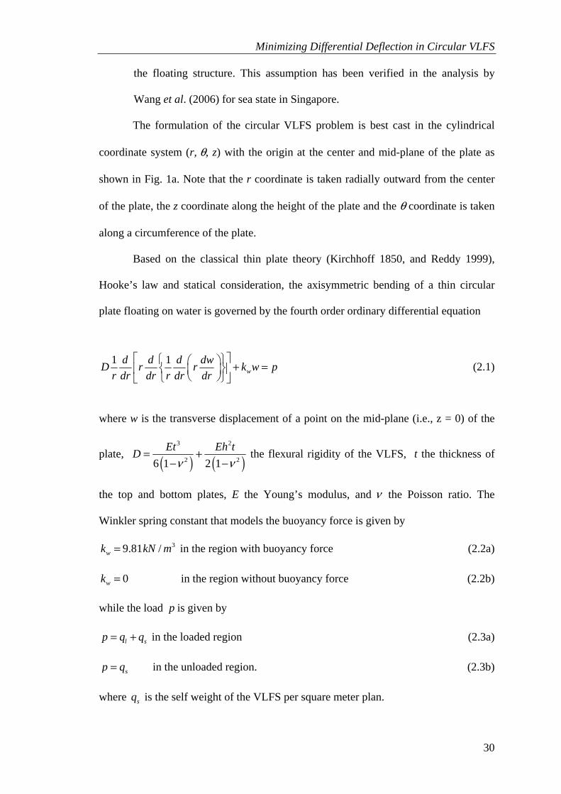
Based on the classical thin plate theory (Kirchhoff 1850, and Reddy 1999),
Hooke’s law and statical consideration, the axisymmetric bending of a thin circular
plate floating on water is governed by the fourth order ordinary differential equation
1 1w
d d d dwD r r k w pr dr dr r dr dr
⎡ ⎤⎧ ⎫⎛ ⎞ + =⎨ ⎬⎢ ⎥⎜ ⎟⎝ ⎠⎩ ⎭⎣ ⎦
(2.1)
where w is the transverse displacement of a point on the mid-plane (i.e., z = 0) of the
plate, ( ) ( )3 2
2 26 1 2 1Et Eh tD
ν ν= +
− − the flexural rigidity of the VLFS, t the thickness of
the top and bottom plates, E the Young’s modulus, and ν the Poisson ratio. The
Winkler spring constant that models the buoyancy force is given by
39.81 /wk kN m= in the region with buoyancy force (2.2a)
0wk = in the region without buoyancy force (2.2b)
while the load p is given by
l sp q q= + in the loaded region (2.3a)
sp q= in the unloaded region. (2.3b)
where sq is the self weight of the VLFS per square meter plan.

Minimizing Differential Deflection in Circular VLFS
31
2. 4 Exact bending solutions and boundary conditions
2.4.1 VLFS regions without buoyancy force
For plate regions with gill cells or stepped plate with smaller depth above water level,
there is no buoyancy force acting on the floating plate. In view of Eq. (2.1), the exact
bending solutions for these regions are given by (Timoshenko and Woinowsky-Krieger
1959)
4
2 21 2 3 4log log
64prw C r r C r C r C
D= + + + + (2.4)
142r
C DprQr
= − − (2.5)
( )
( )
23
1 2 2
33
1 2
3 2 log 3 216
2 log 216
r
Cpr C r CD r
M DCpr C r r r C r
r D rν
⎡ ⎤+ + + −⎢ ⎥
⎢ ⎥= −⎢ ⎥⎧ ⎫+ + + + +⎨ ⎬⎢ ⎥
⎩ ⎭⎣ ⎦
(2.6)
( )
( )
23
1 2 2
33
1 2
3 2 log 3 216
1 2 log 216
Cpr C r CD r
M DCpr C r r r C r
r D r
θ
ν⎡ ⎤⎛ ⎞
+ + + −⎢ ⎥⎜ ⎟⎝ ⎠⎢ ⎥= − ⎢ ⎥⎧ ⎫⎢ ⎥+ + + + +⎨ ⎬
⎢ ⎥⎩ ⎭⎣ ⎦
(2.7)
in which 1 2 3, ,C C C , and 4C are unknown constants, rM the radial bending moment,
θM the circumferential bending moment and rQ the shear force.

Minimizing Differential Deflection in Circular VLFS
32
2.4.2 VLFS regions with buoyancy force
In the view of Eq. (2.1), the exact solutions for the VLFS regions with buoyancy are
given by (Selvadurai 1979)
( ) ( ) ( ) ( )1 1 2 2 3 3 4 4w
pw B Z r l B Z r l B Z r l B Z r lk
= + + + + (2.8)
( ) ( ) ( ) ( )' ' ' '1 2 2 1 3 4 4 33r
DQ B Z r l B Z r l B Z r l B Z r ll⎡ ⎤= − − + −⎣ ⎦ (2.9)
( ) ( ) ( ) ( )
( ) ( ) ( )( ) ( )
1 2 2 1 3 4 4 3
' '1 1 2 22
' '3 3 4 4
1r
B Z r l B Z r l B Z r l B Z r lDM B Z r l B Z r lll
r B Z r l B Z r lν
⎡ ⎤− + −⎢ ⎥
⎧ ⎫= − +⎢ ⎥⎪ ⎪− − ⎨ ⎬⎢ ⎥+ +⎪ ⎪⎢ ⎥⎩ ⎭⎣ ⎦
(2.10)
( ) ( ) ( ) ( )( )
( ) ( ) ( )( ) ( )
1 2 2 1 3 4 4 3
' '2 1 1 2 2
' '3 3 4 4
1
B Z r l B Z r l B Z r l B Z r lDM B Z r l B Z r lll
r B Z r l B Z r lθ
ν
ν
⎡ ⎤− + −⎢ ⎥
= − ⎢ ⎥⎧ ⎫+⎪ ⎪+ −⎢ ⎥⎨ ⎬+ +⎢ ⎥⎪ ⎪⎩ ⎭⎣ ⎦
(2.11)
where 1 2 3, ,B B B and 4B are unknown constants, ( )1 4wl D k= and
( ) ( )( )
( )( )
( )( )
4 8 12
1 2 2 2
2 2 21 ...
2! 4! 6!
x x xZ x = − + − + (2.12)
( ) ( )( )
( )( )
( )( )
2 6 10
2 2 2 2
2 2 2...
1! 3! 5!
x x xZ x = − + − + (2.13)
( ) ( ) ( ) ( ) *3 1 1 2
1 2 log2 2
xZ x Z x R x Z x γπ⎡ ⎤⎧ ⎫= − + ⎨ ⎬⎢ ⎥⎩ ⎭⎣ ⎦
(2.14)
( ) ( ) ( ) ( ) *4 2 2 1
1 2 log2 2
xZ x Z x R x Z x γπ⎡ ⎤⎧ ⎫= + + ⎨ ⎬⎢ ⎥⎩ ⎭⎣ ⎦
(2.15)
with log * 0.57722 ECγ = = (Euler’s constant), and
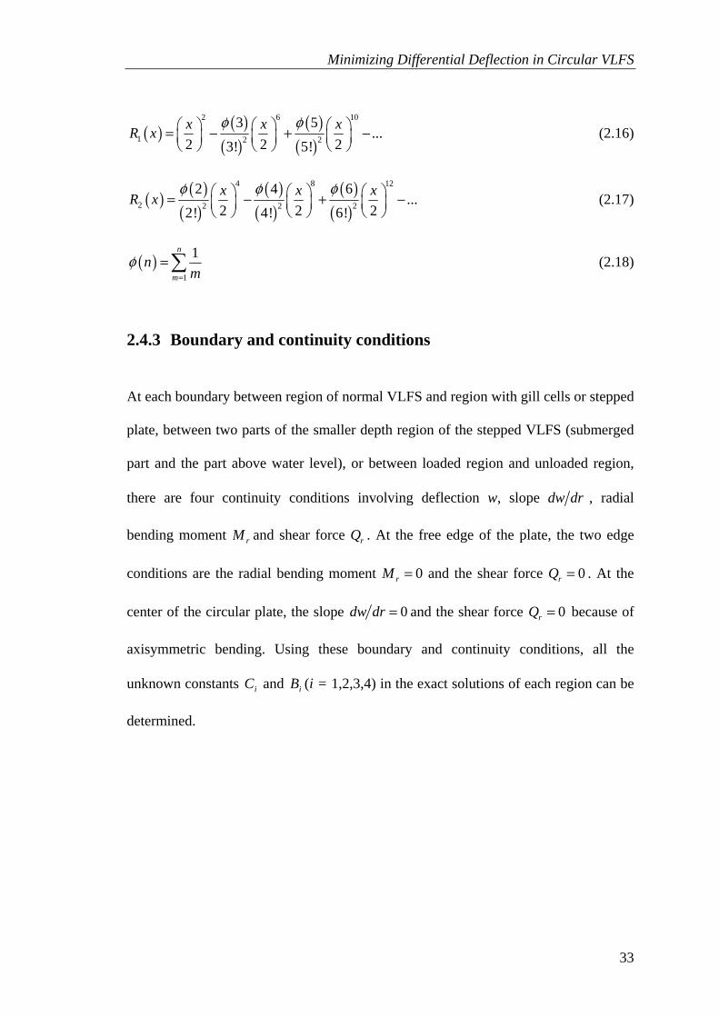
Minimizing Differential Deflection in Circular VLFS
33
( ) ( )( )
( )( )
2 6 10
1 2 2
3 5...
2 2 23! 5!x x xR x
φ φ⎛ ⎞ ⎛ ⎞ ⎛ ⎞= − + −⎜ ⎟ ⎜ ⎟ ⎜ ⎟⎝ ⎠ ⎝ ⎠ ⎝ ⎠
(2.16)
( ) ( )( )
( )( )
( )( )
4 8 12
2 2 2 2
2 4 6...
2 2 22! 4! 6!x x xR x
φ φ φ⎛ ⎞ ⎛ ⎞ ⎛ ⎞= − + −⎜ ⎟ ⎜ ⎟ ⎜ ⎟⎝ ⎠ ⎝ ⎠ ⎝ ⎠
(2.17)
( )1
1n
mn
mφ
=
=∑ (2.18)
2.4.3 Boundary and continuity conditions
At each boundary between region of normal VLFS and region with gill cells or stepped
plate, between two parts of the smaller depth region of the stepped VLFS (submerged
part and the part above water level), or between loaded region and unloaded region,
there are four continuity conditions involving deflection w, slope dw dr , radial
bending moment rM and shear force rQ . At the free edge of the plate, the two edge
conditions are the radial bending moment 0rM = and the shear force 0rQ = . At the
center of the circular plate, the slope 0dw dr = and the shear force 0rQ = because of
axisymmetric bending. Using these boundary and continuity conditions, all the
unknown constants iC and iB (i = 1,2,3,4) in the exact solutions of each region can be
determined.

Minimizing Differential Deflection in Circular VLFS
34
2.5 Results and discussions on effectiveness of gill cells
2.5.1 Basic dimensions and properties of VLFS example, loading and
freeboard conditions
For the example considered, the author will use the dimensions and properties of the
circular VLFS considered by Watanabe et al. (2006). The circular VLFS has R =
200m, h = 2m, t = 0.015m, v = 0.3, E = 2.06x10¹¹N/m2 and γm = 0.25γw where γm is the
density of VLFS and γw the density of water. For the basic loading condition, the
VLFS is considered to carry a uniform load of ql = 30 kN/m2 on the central portion
area bounded by radius r0/R = 0.7. A freeboard that is equal or greater than 0.5h is
specified in order to prevent sea water on the top surface of the floating structure.
2.5.2 Verification of results of VLFS with gill cells
As no analytical results are available, the verification of the analytical model and
equations is established by comparing the analytical solutions written in MATLAB
(2007) against the finite element results obtained from SAP2000 (CSI 2006). For this
purpose, the author considers the gill cells spanning between r1/R = 0.8 and r2/R = 0.9.
A very fine mesh design as shown in Fig. 2.3 is used in SAP2000 in order to
get accurate results. In this mesh, the VLFS is divided into 12000 shell elements
connected by 12001 nodes. The elements connected by the node in the center of VLFS
are three-node triangular shell elements. The other elements are four-node quadrilateral
shell elements. All shell elements are plate type with thickness of 2m. This element
type combines plane stress and plate bending stress. The weight density of the element
is γm = 0.25γw. The rigidity of the element is equal to the rigidity of VLFS in the

Minimizing Differential Deflection in Circular VLFS
35
analytical model. The buoyancy forces in the regions without gill cells are modeled in
SAP2000 by adding springs in vertical direction to the nodes in these regions. The
spring stiffness at each node is calculated by multiplying the Winkler spring constant
wk = 9.81kN/m3 with the associated plan area portions of the plate elements
contributing to that node.
Fig. 2.3 Design mesh of circular VLFS with gill cells used in SAP2000 analysis
It can be seen from Fig. 2.4 that the nondimensional deflections /w w h=
obtained from the two methods agree very well with each other. Therefore the
analytical modeling and equations are correctly set up.

Minimizing Differential Deflection in Circular VLFS
36
0 0.2 0.4 0.6 0.8 1r/R
Analytical solution
Fig. 2.4 Comparison deflections w between analytical solutions and SAP2000 result of circular VLFS with gill cells
2.5.3 Effect of gill cells in reducing differential deflection and stress-
resultants
In order to study the effectiveness of gill cells quantitatively, the author analyzes the
VLFS without and with gill cells. The gill cells are placed in unloaded region with r1/R
= 0.8 and r2/R varying from 0.85 to 0.95.
The nondimensional deflection /w w h= curves in Fig. 2.5 show that VLFS
with gill cells has smaller deflection at its center and larger deflections at the free edge
when compared to its counterpart without gill cells. Therefore, with the introduction of
gill cells in this manner, the maximum differential deflection occurring between the
center and the edge of VLFS is reduced. As r2 increases, this reduction is even more
distinct.
Figure 2.6 shows that VLFS with gill cells has smaller nondimensional shear
force ( )2r rQ Q R D= when compared to its counterpart without gill cells. As r2
w
0
0.5
1
1.5
2
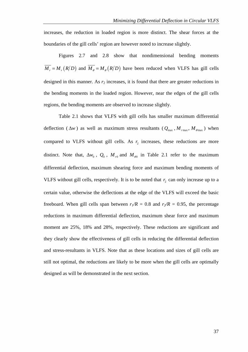
Minimizing Differential Deflection in Circular VLFS
37
increases, the reduction in loaded region is more distinct. The shear forces at the
boundaries of the gill cells’ region are however noted to increase slightly.
Figures 2.7 and 2.8 show that nondimensional bending moments
( )r rM M R D= and ( )M M R Dθ θ= have been reduced when VLFS has gill cells
designed in this manner. As r2 increases, it is found that there are greater reductions in
the bending moments in the loaded region. However, near the edges of the gill cells
regions, the bending moments are observed to increase slightly.
Table 2.1 shows that VLFS with gill cells has smaller maximum differential
deflection ( wΔ ) as well as maximum stress resultants ( maxQ , max max,rM Mθ ) when
compared to VLFS without gill cells. As 2r increases, these reductions are more
distinct. Note that, 0wΔ , 0Q , 0rM and 0Mθ in Table 2.1 refer to the maximum
differential deflection, maximum shearing force and maximum bending moments of
VLFS without gill cells, respectively. It is to be noted that 2r can only increase up to a
certain value, otherwise the deflections at the edge of the VLFS will exceed the basic
freeboard. When gill cells span between r1/R = 0.8 and r2/R = 0.95, the percentage
reductions in maximum differential deflection, maximum shear force and maximum
moment are 25%, 18% and 28%, respectively. These reductions are significant and
they clearly show the effectiveness of gill cells in reducing the differential deflection
and stress-resultants in VLFS. Note that as these locations and sizes of gill cells are
still not optimal, the reductions are likely to be more when the gill cells are optimally
designed as will be demonstrated in the next section.

Minimizing Differential Deflection in Circular VLFS
38
0r/R
00.2 0.4 0.6 0.8 1
R1r2r
Gill cells0rq
h
l
No gill cells
(r / R = 10.80
r / R = 2 0.85)
(r / R = 0.80r / R = 0.90)
(r / R = 0.80r / R = 0.95)
w
12
12
0.5
1
1.5
2 Fig. 2.5 Effect of gill cells on deflections w
-2
-1.5
-1
-0.5
0
0.5
1
0 0.2 0.4 0.6 0.8 1r /R
Fig. 2.6 Effect of gill cells on shear force rQ
No gill cells r1/R = 0.8, r2/R = 0.85 r1/R = 0.8, r2/R = 0.90 r1/R = 0.8, r2/R = 0.95
Qr

Minimizing Differential Deflection in Circular VLFS
39
-0.1
-0.05
0
0.05
0.1
0.15
0 0.2 0.4 0.6 0.8 1r/R
Fig. 2.7 Effect of gill cells on radial moment rM
-0.05
-0.025
0
0.025
0.05
0.075
0.1
0 0.2 0.4 0.6 0.8 1r/R
Fig. 2.8 Effect of gill cells on circumferential moment θM
Mr
No gill cells r1/R = 0.8, r2/R = 0.85 r1/R = 0.8, r2/R = 0.90 r1/R = 0.8, r2/R = 0.95
Mθ
No gill cells r1/R = 0.8, r2/R = 0.85 r1/R = 0.8, r2/R = 0.90 r1/R = 0.8, r2/R = 0.95

Minimizing Differential Deflection in Circular VLFS
40
Table 2.1 Effect of gill cells in reducing maximum differential deflection and maximum stress-resultants
2 /r R For 1 0.80r R =
0.85 0.90 0.95
0/w wΔ Δ 0.9557 0.8839 0.7490
max 0Q Q 0.8989 0.8420 0.8220
max 0r rM M 0.9348 0.8470 0.8111
max 0M Mθ θ 0.9317 0.8466 0.7236
2.6 Optimal design/location of gill cells in circular VLFS
For a circular VLFS with prescribed dimensions, material properties, loading and
freeboard conditions, the optimization problem at hand is to optimally design the gill
cells, that is, to determine the optimal values of r1 and r2 (Fig. 2.1) that minimize the
differential deflection which is assumed to be the difference between the deflections at
the center wc and at the edge we of the VLFS. The constrained optimization problem
may be mathematically stated as
( )
( )1 2, c er r
Min w w−
subject to e fw h h≤ −
gmw h≤
0 1 2r r r R≤ ≤ ≤ (2.19)
where hf is the height of the freeboard at the edge of the VLFS, and wgm the maximum
deflection in the gill cell region.

Minimizing Differential Deflection in Circular VLFS
41
The constrained optimization problem is solved using the MATLAB
Optimization Toolbox. The toolbox uses sequential quadratic programming (SQP)
implementation which is a generalization of Newton’s method. The SQP
implementation consists of three main stages including updating of the Hessian matrix
of the Lagrangian function (Powell 1978), quadratic programming problem solution
(Gill et al. 1984 and 1991), and line search and merit function calculation (Han 1997).
The optimal design of gill cells is defined by r1 and r2 and these radii depend
on various parameters including loading magnitude, radius of loading area, thickness
of top and bottom plates and the freeboard condition at the edge of VLFS. The optimal
design of gill cells for minimum differential deflection and reducing stress-resultants
will be investigated for four different cases, each case to assess the sensitivity of the
aforementioned parameters.
2.6.1 Case 1 - Varying loading magnitudes ql
The author adopts the dimensions and properties of VLFS and the freeboard condition
as in the part 2.5.1. In this case, the VLFS is considered to carry a uniform load ql with
magnitudes ranging from 0.6q0 to 1.6q0 (where q0 = 30 kN/m2) on the central portion
confined by the radius 0 0.7r R= .
Figure 2.9 shows that as ql increases, both r1 and r2 increase but r1 seems to
increase slightly faster than r2. This means that the optimal design of gill cells is
slightly smaller and the cells are located closer to the edge of the VLFS.

Minimizing Differential Deflection in Circular VLFS
42
0.7
0.8
0.9
1
0.6 0.8 1 1.2 1.4 1.6q l/q 0
Opt
imal
r1/R
, r2/R
Fig. 2.9 Optimal design of gill cells when varying ql
0.4
0.6
0.8
1
0.6 0.8 1 1.2 1.4 1.6q l/q 0
Max
imum
diff
eren
tial d
efle
ctio
n te
an
d st
ress
-res
ulta
nts r
atio
s f g
Fig. 2.10 Effect of optimal gill cells when varying ql
The sensitivity of the optimal design of gill cells in reducing the maximum
differential deflection and stress-resultants is shown in Fig. 2.10. The 40% reduction
achieved for the maximum differential deflection is significant. As ql increases, this
percentage reduction decreases. For 0 00.6 0.7lq q q≤ ≤ , the optimal design of gill cells
r2/R r1/R
Δw/Δw0 Qmax/Q0 Mrmax/Mr0 Μθmax/Μθ0

Minimizing Differential Deflection in Circular VLFS
43
led to a further reduction in the maximum bending moments as ql increases from 06.0 q
to 00.7q . However, for 0 00.7 1.6lq q q≤ ≤ , the reduction in the maximum bending
moment becomes smaller as ql increases from 00.7q to 06.1 q . Similarly, for
0 l 00.6 0.75q q q≤ ≤ , the presence of the optimal gill cells led to a further reduction in
the maximum shear force as ql increases from 06.0 q to 00.75q and when
0 l 00.75 1.6q q q≤ ≤ , the reduction in the maximum shear force becomes smaller as ql
increases from 00.75q to 06.1 q . In sum, the maximum percentage reduction in the
maximum shear force is approximately 55% when ql/q0 is 0.75 while the maximum
percentage reduction in the maximum bending moments is approximately 45% when
ql/q0 is 0.70.
2.6.2 Case 2 - Varying loading radius r0
The same dimensions and properties of VLFS and the freeboard condition are adopted.
In this case, the considered VLFS is to carry a uniform load of 30 kN/m2 over its
central area bounded by the radius 0r which the author shall vary from 0.4R to 0.85R.
Figure 2.11 shows that as the loading area radius r0 increases but is within
0.78R, both radii r1 and r2 increase with r1 increasing faster than r2. This means that
the optimal design of gill cells is smaller and located closer to the edge of the VLFS
for the loading configuration. When the loading radius becomes large, i.e r0 > 0.78R,
the optimal design of gill cells utilizes a relatively small area so as to ensure the
condition of freeboard at the edge of VLFS is satisfied.
As shown in Fig. 2.12, when the loading radius 0r increases, the reduction in
maximum shear force increases except for r0 > 0.82R. After 0r passes 0.82R, the

Minimizing Differential Deflection in Circular VLFS
44
reduction in the maximum shear force decrease gradually. Figure 2.12 also shows that,
when the loading radius r0 < 0.78R, the reductions in the maximum differential
deflection and bending moments are significant and their maximum percentage
reductions are 28% and 37%, respectively. Considering loading radius r0 > 0.78R, any
increase in the loading radius leads to smaller percentage reductions in the maximum
differential deflection and bending moments. In summary, the optimal design of gill
cells seems to be most effective in reducing the maximum differential deflection and
the maximum stress-resultants when 0.5R < r0 < 0.75R.
0.5
0.6
0.7
0.8
0.9
1
0.4 0.5 0.6 0.7 0.8 0.9r 0/R
Opt
imal
r1/R
, r2/R
Fig. 2.11 Optimal design of gill cells when varying r0
r2/R r1/R

Minimizing Differential Deflection in Circular VLFS
45
0.6
0.7
0.8
0.9
0.4 0.5 0.6 0.7 0.8 0.9r 0/R
Max
imum
diff
eren
tial d
efle
ctio
n df
an
d st
ress
-res
ulta
nts r
atio
s d
f
Fig. 2.12 Effect of optimal gill cells when varying r0
2.6.3 Case 3 - Varying top and bottom plate thicknesses t
In this case study, the same loading and freeboard conditions in the first example are
adopted. The same dimensions and properties of VLFS are also assumed except for the
top and bottom plate thickness t which now varies from 0.5t0 to 2.5t0 (in which t0 =
0.015 m).
The optimal design of gill cells is shown in Fig. 2.13. It may be observed that
the optimal design of gill cells does not change much with varying top and bottom
plate thicknesses t. As the plate thickness t increases, r1 is observed to remain
approximately constant while r2 decreases gradually.
As shown in Fig. 2.14, when the plate thickness t increases, the reduction in
maximum shear force increases but the reductions in maximum differential deflection
and bending moments seem to decrease gradually. The maximum percentage
Δw/Δw0 Qmax/Q0 Mrmax/Mr0 Μθmax/Μθ0
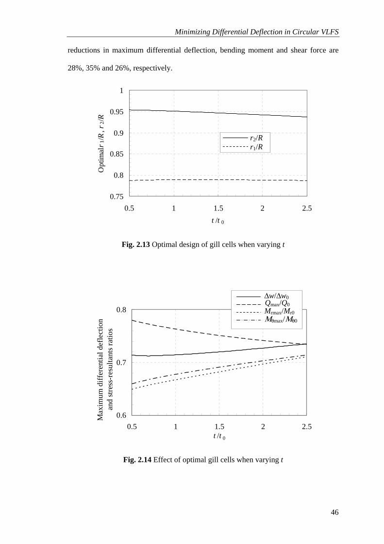
Minimizing Differential Deflection in Circular VLFS
46
reductions in maximum differential deflection, bending moment and shear force are
28%, 35% and 26%, respectively.
0.75
0.8
0.85
0.9
0.95
1
0.5 1 1.5 2 2.5t /t 0
Opt
imal
r 1/R
, r2/R
Fig. 2.13 Optimal design of gill cells when varying t
0.6
0.7
0.8
0.5 1 1.5 2 2.5t /t 0
Max
imum
diff
eren
tial d
efle
ctio
n
df
and
stre
ss-r
esul
tant
s rat
ios
df
Fig. 2.14 Effect of optimal gill cells when varying t
r2/R r1/R
Δw/Δw0 Qmax/Q0 Mrmax/Mr0 Μθmax/Μθ0
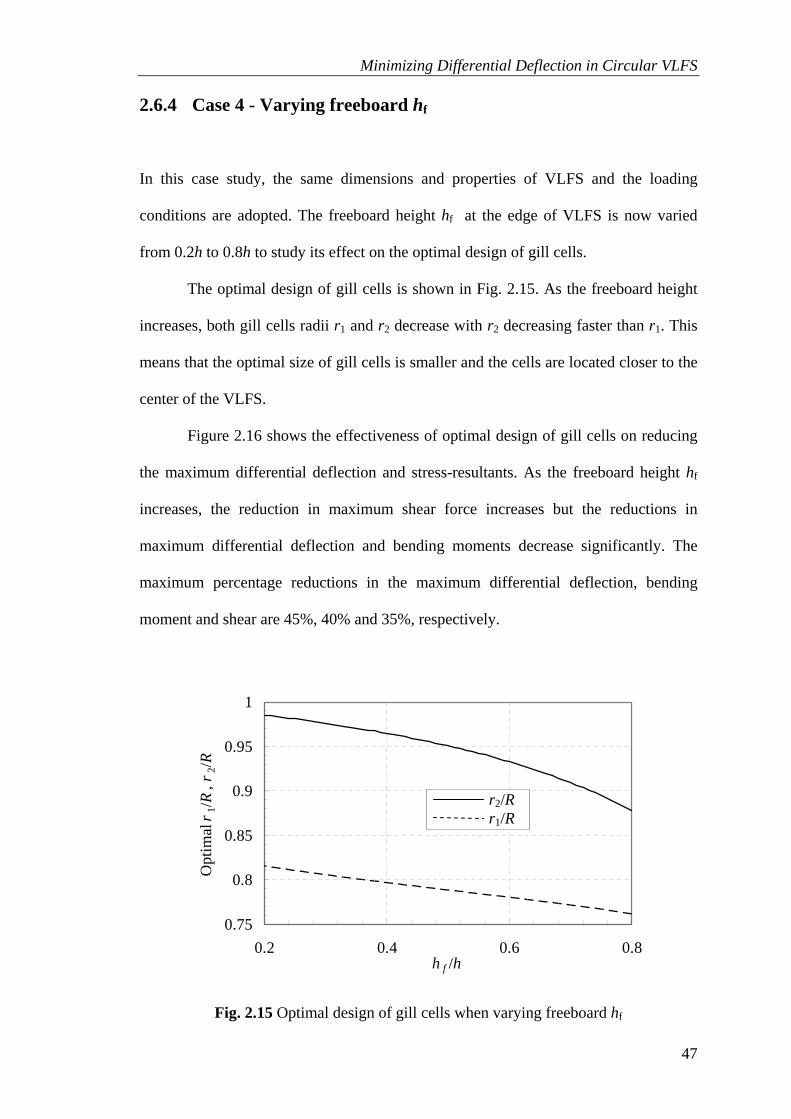
Minimizing Differential Deflection in Circular VLFS
47
2.6.4 Case 4 - Varying freeboard hf
In this case study, the same dimensions and properties of VLFS and the loading
conditions are adopted. The freeboard height hf at the edge of VLFS is now varied
from 0.2h to 0.8h to study its effect on the optimal design of gill cells.
The optimal design of gill cells is shown in Fig. 2.15. As the freeboard height
increases, both gill cells radii r1 and r2 decrease with r2 decreasing faster than r1. This
means that the optimal size of gill cells is smaller and the cells are located closer to the
center of the VLFS.
Figure 2.16 shows the effectiveness of optimal design of gill cells on reducing
the maximum differential deflection and stress-resultants. As the freeboard height hf
increases, the reduction in maximum shear force increases but the reductions in
maximum differential deflection and bending moments decrease significantly. The
maximum percentage reductions in the maximum differential deflection, bending
moment and shear are 45%, 40% and 35%, respectively.
0.75
0.8
0.85
0.9
0.95
1
0.2 0.4 0.6 0.8h f /h
Opt
imal
r1/R
, r2/R
Fig. 2.15 Optimal design of gill cells when varying freeboard hf
r2/R r1/R

Minimizing Differential Deflection in Circular VLFS
48
0.5
0.6
0.7
0.8
0.9
1
0.2 0.4 0.6 0.8h f /h
Max
imum
diff
eren
tial d
efle
ctio
n df
an
d str
ess-
resu
ltant
s ra
tios
df
Fig. 2.16 Effect of optimal gill cells when varying freeboard hf
2.7 Comparing the effectiveness of gill cells with stepped VLFS
The author will compare the effectiveness in reducing the differential deflection of
optimal design of gill cells in VLFS with that of optimal stepped VLFS (optimal
values of the radii 1r and 2r in Fig 2.1c). The volume of the stepped plate is kept the
same as the volume of the reference constant thickness plate. As shown in Fig. 2.1, the
constant thickness of the reference plate as h, the thickness of the stepped plate are
related to h, via the constant volume constraint, in the following manner
Δw/Δw0 Qmax/Q0 Mrmax/Mr0 Μθmax/Μθ0

Minimizing Differential Deflection in Circular VLFS
49
( )1 2 2
1 21 1
hhr rR R
α=
⎛ ⎞⎛ ⎞ ⎛ ⎞+ − −⎜ ⎟⎜ ⎟ ⎜ ⎟⎜ ⎟⎝ ⎠ ⎝ ⎠⎝ ⎠
(2.20)
2 1h hα= (2.21)
where 2 1 1h h= <α controls the change in the thickness of the stepped plate.
2.7.1 Case 1 - Varying loading magnitudes ql
The author adopts the basic dimensions and properties of VLFS and the freeboard
condition as in section 2.5.1. For stepped VLFS, the author adopts basic
ratio 2 1 0.5h h= =α . In this case, the VLFS is considered to carry a uniform load ql
with magnitudes ranging from 0.5q0 to 1.5q0 (where q0 = 30 kN/m2) on the central
portion confined by the radius 0 0.7r R= .
Figure 2.17 shows the effect of optimal design of gill cells in VLFS and
optimal stepped. Both methods are effective in reducing the maximum differential
deflection of VLFS. We see clearly that using gill cells gives more reduction in
maximum differential deflection in VLFS than using stepped VLFS about 18% in
every loading conditions.

Minimizing Differential Deflection in Circular VLFS
50
0.4
0.6
0.8
1
0.5 0.7 0.9 1.1 1.3 1.5q l/q 0
Stepped VLFSGill cells
Fig. 2.17 Effect of optimal gill cells and optimal stepped VLFS when varying ql
2.7.2 Case 2 - Varying loading radius r0
The same basic dimensions and properties of VLFS and the freeboard condition with
case 1 are adopted. In this case, the considered VLFS is to carry a uniform load of 30
kN/m2 over its central area bounded by the radius 0r which the author shall vary from
0.5R to 0.9R.
Figure 2.18 shows the effect of optimal design of gill cells in VLFS and
optimal stepped. Both methods are effective in reducing the maximum differential
deflection of VLFS. We see clearly that using gill cells gives more reduction in
maximum differential deflection in VLFS than using stepped VLFS. Only when the
loading radius r0 > 0.88R, stepped VLFS is more effective than gill cells. However,
this loading radius condition is not common in VLFS as the edge area of VLFS is used
for quay crane.
Max
imum
diff
eren
tial d
efle
ctio
n ra
tio Δ
w/Δ
w0

Minimizing Differential Deflection in Circular VLFS
51
0.6
0.7
0.8
0.9
1
0.5 0.6 0.7 0.8 0.9r 0/R
Stepped VLFSGill cells
Fig. 2.18 Effect of optimal gill cells and optimal stepped VLFS when varying r0
2.7.3 Case 3 - Varying top and bottom plate thicknesses t
In this case study, the same basic loading and freeboard conditions are adopted. The
same dimensions and properties of VLFS are also assumed except for the top and
bottom plate thickness t which now varies from 0.5t0 to 2.5t0 (in which t0 = 0.015 m).
Figure 2.19 shows the effect of optimal design of gill cells in VLFS and
optimal stepped. Both methods are effective in reducing the maximum differential
deflection of VLFS. We see clearly that using gill cells gives more reduction in
maximum differential deflection in VLFS than using stepped VLFS about 20%.
Max
imum
diff
eren
tial d
efle
ctio
n ra
tio Δ
w/Δ
w0

Minimizing Differential Deflection in Circular VLFS
52
0.6
0.7
0.8
0.9
0.5 1 1.5 2 2.5t /t 0
Stepped VLFSGill cells
Fig. 2.19 Effect of optimal gill cells and optimal stepped VLFS when varying t
2.8 Optimal design/location of gill cells in annular VLFS
2.8.1 Dimensions, properties of annular VLFS and proposed gill cells
location
As the load is not uniformly distributed over the entire floating structure as shown in
Fig. 2.2, it causes a deformed shape with a large slope in the structure. Owing to the
axisymmetric nature of the considered VLFS and the loading condition, it is proposed
that the gill cells be located as shown in Fig. 2.20. The gill cells compartments are
bounded in two regions by the radii r1, r2, r5, and r6 such that 0 1 2 3r r r r≤ ≤ ≤ and
4 5 6r r r R≤ ≤ ≤ .The problem at hand is to minimize the maximum slope as well as to
reduce the stress-resultants by finding the optimal values of these radii.
Max
imum
diff
eren
tial d
efle
ctio
n ra
tio Δ
w/Δ
w0

Minimizing Differential Deflection in Circular VLFS
53
r
q
0h
l
rr
14
Rr6
r5
r4r3
r2 r1
r 0
Gill cells' regions
r2
r3
rrR
56
Fig. 2.20 Annular VLFS with gill cells.
For the example considered, the author shall use the dimensions and properties
of the thin circular VLFS considered by Watanabe, et al. (2006) and cut out a central
circular portion of 0 0.2r R= . The ring-shape VLFS has R = 200m, r0 = 40m, h = 2m, t
= 0.015m, v = 0.3, E = 2.06x10¹¹ N/m2 and γm = 0.25γw where γm is the weight density
of VLFS and γw the weight density of water. The VLFS is considered to carry a
uniform load of ql = 25 kN/m2 on a portion area bounded by radii r3/R = 0.5 and r4/R =
0.7. An allowable draft at free edges that is equal or less than 0.7h is specified.
2.8.2 Optimization formulation
For an annular VLFS with prescribed dimensions, material properties, loading and
freeboard conditions, the optimization at hand is to optimally design the gill cells, that
is, to determine the optimal values of r1, r2, r5, and r6 that minimize the slope of the
VLFS. The constrained optimization problem may be mathematically stated as

Minimizing Differential Deflection in Circular VLFS
54
( ) ( )
( )1 2 5 6 0, , ,r r r r r r RMin Max dw
= ÷
⎛ ⎞⎜ ⎟⎝ ⎠
subject to e fw h h≤ − , gmw h≤ ,
0 1 2 3 4 5 6andr r r r r r r R≤ ≤ ≤ ≤ ≤ ≤ (2.22)
where hf = 0.3h is the allowable freeboard at the free edges of the VLFS, we the
maximum deflection at the free edges of VLFS, and wgm the maximum deflection in
the gill cell regions.
The slope function in VLFS is continuous and differentiable. So at each design
(location and size) of gill cells, the maximum slope is found by using MATLAB
Optimization Toolbox in which classical optimization algorithms is fully updated.
Obviously, the problem of determining the maximum slopes at different designs of gill
cells is stochastic in nature and does not follow a continuous and differentiable
function. Therefore, the minimization of the maximum slope problem cannot be solved
by any classical optimization algorithm. So MATLAB Genetic Algorithm and Direct
Search Toolbox is used to seek the optimal number and locations of gill cells that
minimize the maximum slope.
2.8.3 Optimization result
By carrying out the optimization exercise, the author found the optimal design of gill
cells to be bounded by radii r1 = 40.9177m, r2 = 65.2682m, r5 = 171.6198m, and r6 =
196.9966m. The slope curves in Fig. 2.21 show that VLFS with optimal gill cells has a
significantly smaller slope when compared to its counterpart without gill cells. Table
2.2 shows that VLFS with optimal gill cells has significantly smaller maximum slope
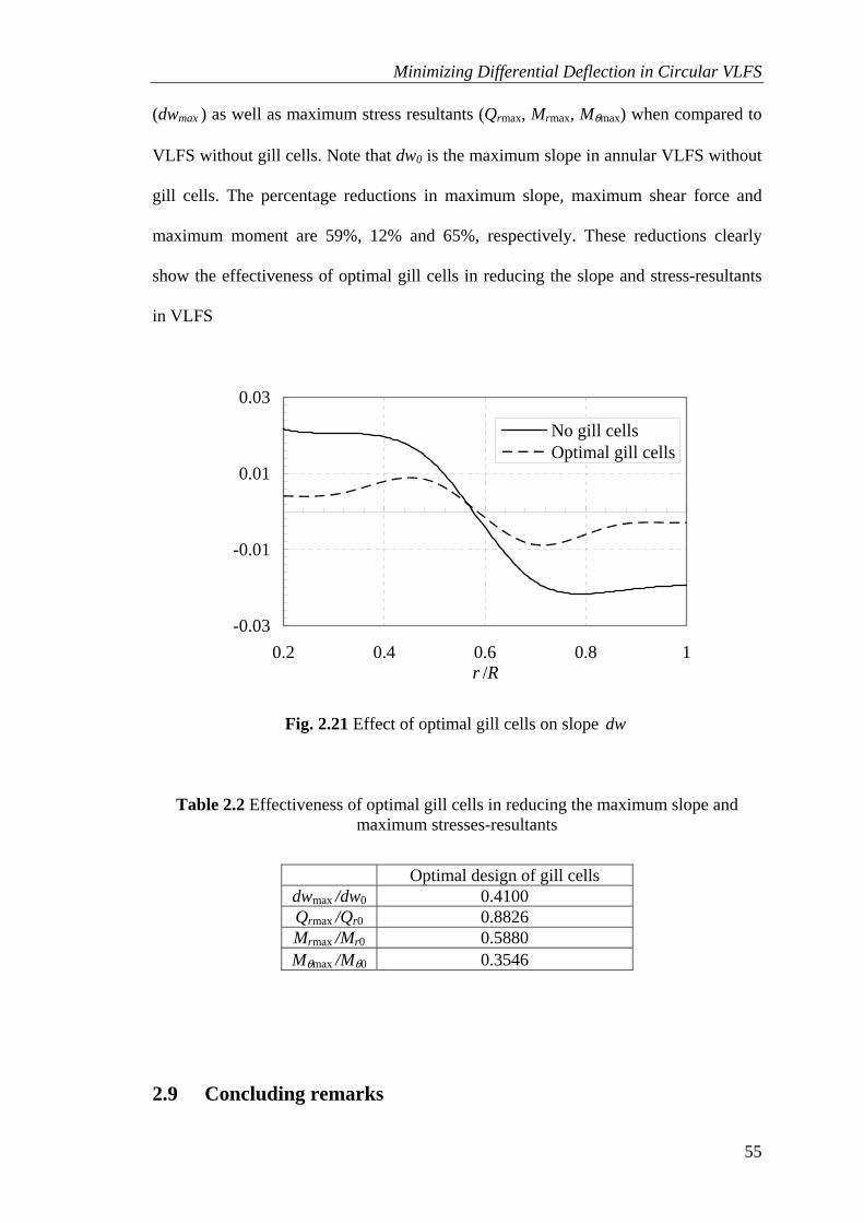
Minimizing Differential Deflection in Circular VLFS
55
(dwmax ) as well as maximum stress resultants (Qrmax, Mrmax, Mθmax) when compared to
VLFS without gill cells. Note that dw0 is the maximum slope in annular VLFS without
gill cells. The percentage reductions in maximum slope, maximum shear force and
maximum moment are 59%, 12% and 65%, respectively. These reductions clearly
show the effectiveness of optimal gill cells in reducing the slope and stress-resultants
in VLFS
-0.03
-0.01
0.01
0.03
0.2 0.4 0.6 0.8 1r /R
No gill cellsOptimal gill cells
Fig. 2.21 Effect of optimal gill cells on slope dw
Table 2.2 Effectiveness of optimal gill cells in reducing the maximum slope and maximum stresses-resultants
Optimal design of gill cells dwmax /dw0 0.4100 Qrmax /Qr0 0.8826 Mrmax /Mr0 0.5880 Mθmax /Mθ0 0.3546
2.9 Concluding remarks

Minimizing Differential Deflection in Circular VLFS
56
The effect of gill cells in reducing differential deflection and stress-resultants in
pontoon-type, circular VLFS under a confined central uniform load has been
investigated. The optimal design of gill cells with the view to minimizing the
differential deflection and stress-resultants has been carried out. The study conducted
considered a number of design parameters such as the loading magnitude, the radius of
the loading area, the thicknesses of the top and bottom plates and the freeboard height
at the edge of VLFS. The results show that
1) Gill cells, when designed appropriately, are effective in reducing the maximum
differential deflection and stress-resultants. The percentage reductions in the
maximum differential deflection, bending moments and shear force can be up
to 45%, 45% and 55%, respectively, for the example considered.
2) When the thicknesses of the top and bottom plates and the freeboard height of
the circular VLFS are increased, the optimal design of gill cells is more
effective in reducing the maximum shear force but is comparatively less
effective in reducing the maximum differential deflection and bending
moments.
3) The optimal design of gill cells is most effective when the radius of the loading
area is bounded by the radius that varies from 0.5R to 0.75R and when the
loading magnitude is not too large.
This chapter also compared the effectiveness in reducing the differential
deflection in circular VLFS by using gill cells and varying heights of VLFS. In both
cases, the same volume was used. The obtained results show that both methods are
effective in reducing the maximum differential deflection in VLFS. However, using
gill cells in VLFS is found more effective than using varying heights of VLFS.

Minimizing Differential Deflection in Circular VLFS
57
By using gill cells in an annular VLFS, the optimal design of gill cells with the
view to minimizing the slope and reducing the stress-resultants has been investigated.
The obtained results show that optimal design of gill cells in annular VLFS can reduce
the maximum slope, shear force and bending moment up to 59%, 12% and 65%,
respectively for the example considered. These reductions are significant and clearly
show the effectiveness of gill cells in reducing the slope and stress-resultants.
58
CHAPTER 3
MINIMIZING DIFFERENTIAL DEFLECTION IN
NON-CIRCULAR SHAPED VLFS USING GILL
CELLS
3.1 Introduction
In the previous chapter, we have minimized the differential deflection in a circular
VLFS and bending slope in an annular VLFS by using gill cells by analytical method.
In practice, VLFS can take on any shape (Watanabe 2004a) and an analytical method
for seeking the optimal design of gill cells is not possible. So in this chapter, we seek
the optimal layout (number and locations) of gill cells in an arbitrarily shaped VLFS
with the view to minimizing the differential deflection using a numerical technique. In
this technique, we developed finite plate elements based on the Mindlin plate theory
(Mindlin 1951) to model the VLFS so that more accurate bending results, especially
the stress resultants, may be obtained. The buoyancy forces are modeled as Winkler
springs. At the gill cell locations, the Winkler springs are removed since there are no
buoyancy forces.
Unlike the circular VLFS treated in Chapter 2, the objective function (which is
the differential deflection) of the optimization problem for an arbitrarily shaped VLFS
does not have an explicit analytical form because it has to be determined numerically.
Hence it lacks the continuous and differentiable function form. Therefore, the
59
optimization problem cannot be solved by any classical optimization algorithms that
require a continuous and differential objective function. Since the gill cell number and
locations are the variables in the optimization problem, we believe that genetic
algorithms (GA) are ideal for seeking these optimal variables that minimize the
maximum differential deflection.
3.2 Problem definition
Although the algorithm developed here could be used to handle any VLFS shape and
loading pattern, we shall consider some common shapes such as square, rectangular
and I-shape under symmetrical loading pattern for analysis and discussion. The I-shape
is considered as it provides more edge length for ship to berth. The flat box-like
VLFSs have an overall depth h, top and bottom plate thickness t and carrying a
uniform load ql on a central portion as shown in Fig. 3.1. Owing to the symmetry in
shape and loading conditions considered for these VLFS problems, we will analyze
only a quarter of the structure. As the load is not uniformly distributed over the entire
floating structures, the deflection surface is not uniform.
VLFS comprises many watertight compartments to provide the necessary
buoyancy. Gill cells are compartments without buoyancy because they have holes or
slits at their bottom floors that allow water to flow in and out freely. At the gill cells
locations, the buoyancy force is eliminated. The problem at hand is to seek the optimal
layout (number and positions) of gill cells that will minimize the maximum differential
deflection of VLFS under the non-uniform load.

60
30 120 30 30240
3018
030
240
Aea lq
30
Loading
Lc
Lc A
A
180 30240
3018
030
240
Aea lq
30
Loading
Lc
Lc A
A Note: all dimensions are in meter
180 30240
3012
030
180
Aea lq
30
Loading
Lc
Lc
A A
t=0.
03
180 30240
30
lq
Section A-A
h=3 VLFS
Fig. 3.1 Square, rectangular and I-shaped VLFSs
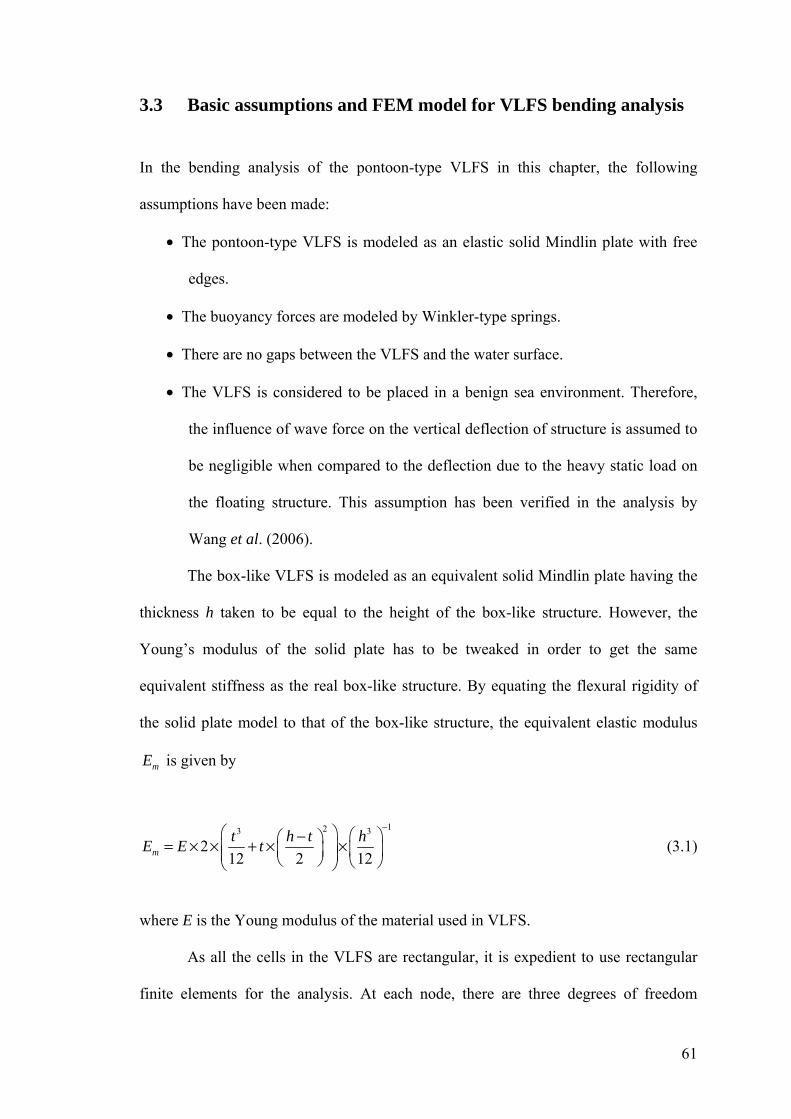
61
3.3 Basic assumptions and FEM model for VLFS bending analysis
In the bending analysis of the pontoon-type VLFS in this chapter, the following
assumptions have been made:
• The pontoon-type VLFS is modeled as an elastic solid Mindlin plate with free
edges.
• The buoyancy forces are modeled by Winkler-type springs.
• There are no gaps between the VLFS and the water surface.
• The VLFS is considered to be placed in a benign sea environment. Therefore,
the influence of wave force on the vertical deflection of structure is assumed to
be negligible when compared to the deflection due to the heavy static load on
the floating structure. This assumption has been verified in the analysis by
Wang et al. (2006).
The box-like VLFS is modeled as an equivalent solid Mindlin plate having the
thickness h taken to be equal to the height of the box-like structure. However, the
Young’s modulus of the solid plate has to be tweaked in order to get the same
equivalent stiffness as the real box-like structure. By equating the flexural rigidity of
the solid plate model to that of the box-like structure, the equivalent elastic modulus
mE is given by
123 3
212 2 12
−⎛ ⎞ ⎛ ⎞−⎛ ⎞= × × + × ×⎜ ⎟ ⎜ ⎟⎜ ⎟⎜ ⎟⎝ ⎠ ⎝ ⎠⎝ ⎠m
t h t hE E t (3.1)
where E is the Young modulus of the material used in VLFS.
As all the cells in the VLFS are rectangular, it is expedient to use rectangular
finite elements for the analysis. At each node, there are three degrees of freedom

62
, ,x yw φ φ in which w is the vertical displacement, xφ and yφ denote rotations about the
y and x axes, respectively. The definitions of vertical displacement and rotations are
shown in Fig. 3.2.
xy
y x
w, z
φ
φ
Fig. 3.2 Definitions of deflection and rotations
The vector sum of displacement and rotation angles includes twelve degrees of
freedom in an element, i.e.
1 1 1 2 2 2 4 4 4w ⎡ ⎤= ⎣ ⎦i x y x y x yw w wφ φ φ φ φ φ (3.2)
From this vector, the displacement and strain vectors are expressed as:
w N w= w i (3.3)
ε B wx y xy iz χε ε γ⎡ ⎤= =⎣ ⎦ (3.4)
xzγ B w⎡ ⎤= =⎣ ⎦yz iγγ γ (3.5)
where Nw is the shape functions, Bχ the curvature-displacement matrix, and Bγ the
shear strain displacement matrix
According to the principle of virtual work, we can write
( )Tε σdv γ τdv w w dAT TS w
V V A
K p kδ δ δ+ = −∫ ∫ ∫ (3.6)

63
{ }B D B dA B D B dA N N dA N dA⎛ ⎞
+ + =⎜ ⎟⎝ ⎠∫ ∫ ∫ ∫T T T w T
b S w i wA A A A
k w pχ χ γ γ (3.7)
[ ]{ } { }K w F=i i (3.8)
where 6/5=sK is the shear correction factor for the Mindlin plate, Db the bending
stiffness matrix, DS the shear stiffness matrix, [K] stiffness matrix and {Fi} the force
matrix.
( )3
2
1 0D 1 0
12 1 10 02
b
vEt v
v v
⎡ ⎤⎢ ⎥⎢ ⎥
= ⎢ ⎥− ⎢ ⎥−⎢ ⎥⎣ ⎦
(3.9)
( )1 0
D0 12 1
SS
K Etv⎡ ⎤
= ⎢ ⎥+ ⎣ ⎦ (3.10)
The Winkler spring constant wk in Eqs. (3.6) and (3.7) that models the
buoyancy force is given by
39.81 /wk kN m= in the region without gill cells (3.11a)
0wk = in the region with gill cells (3.11b)
while the load p is given by
= +l sp q q in the loaded region (3.12a)
= sp q in the unloaded region (3.12b)
in which sq is the self weight of the VLFS per square meter.
Based on the foregoing equations, a finite element method (FEM) program is
developed in MATLAB (2007) for the bending analysis.

64
3.4 Results and discussions on effectiveness of gill cells
3.4.1 Dimensions and properties of VLFS examples, loading and
freeboard conditions
The dimensions of the considered VLFSs are shown in Fig. 3.1. The material
properties, adopted from Chen et al. (2003), are: Poisson’s ratio 0.13=v , Young’s
modulus 10 21.19 10 N m= ×mE and weight density 3256.25kg m=mγ . We assumed
that top and bottom plates of VLFSs are made of steel with thickness 0.03m=t and
Young’s modulus 11 22.0 10 N m= ×E . From Eq. (3.1), we can get the equivalent
Young’s modulus Em. The VLFSs are assumed to be subjected to a uniform distributed
load of 230kN m=lq over the central portion as shown in Fig. 3.1. A freeboard that is
equal or greater than 0.25h is specified in order to prevent green water on the top
surface of the floating structures.
3.4.2 Verification of results
The verification of the developed FEM model is established by comparing the FEM
results with the results obtained from the commercial software SAP2000 (CSI 2006).
For this purpose, we consider a quarter of the square VLFS without gill cells and with
gill cells as shown in Fig. 3.5b with the unshaded compartments denoting normal
VLFS and shaded compartments denoting the gill cells. A mesh design, as shown in
Fig. 3.5b, is used for both the present FEM model and the SAP2000 model. In this
mesh, a quarter of the VLFS is divided into 576 equal four-node quadrilateral plate
elements connected by 625 nodes. The buoyancy forces in the regions without gill

65
cells are modeled in SAP2000 by adding springs in the vertical direction to the nodes
in these regions. The spring stiffness at each node is calculated by multiplying the
Winkler spring constant wk with the associated plan area portions of the plate elements
that contribute to that node.
It can be seen from Figs. 3.3 and 3.4 that the nondimensionalized deflection
contours =w w h obtained from the two computer codes agree very well for both the
VLFS with and without gill cells cases. Therefore, the present FEM model is correctly
set up and will be used to analyze the bending of VLFSs.
3.4.3 Effect of gill cells in reducing differential deflection and von
Mises stress
In order to study the effectiveness of gill cells quantitatively, we analyze the square
VLFS with and without gill cells. The gill cells are placed in the unloaded region as
shown in Fig. 3.5b. Figures 3.3 and 3.4 show the deflection contours of the VLFS with
and without gill cells, respectively. It can be seen that the deflection contour of VLFS
with gill cells is significantly flatter. Furthermore, the percentage reductions in the
maximum differential deflection and the maximum von Mises stress are about 21%
and 10%, respectively. These reductions are significant and clearly show the
effectiveness of gill cells. Note that as these gill cells are still not optimal, the
reductions are likely to be greater when the gill cells are optimally placed as will be
demonstrated in the optimization exercise later.

66
0.1
0.2
0.3
0.4
0.5
0.6
0.7
0.8
0.9
1.0
1.1
1.2
(a) Using current FEM model
0.1
0.2
0.3
0.4
0.5
0.6
0.7
0.8
0.9
1.0
1.1
1.2
(b) Using SAP2000
Fig. 3.3 Nondimensionalized deflection contour w in a quarter of the square VLFS without gill cells

67
0.3
0.4
0.5
0.6
0.7
0.8
0.9
1.0
1.1
1.2
(a) Using current FEM model
0.3
0.4
0.5
0.6
0.7
0.8
0.9
1.0
1.1
1.2
(b) Using SAP2000
Fig. 3.4 Nondimensionalized deflection contour w in a quarter of the square VLFS with gill cells
3.5 Optimization problems
For a VLFS with prescribed dimensions, material properties, loading and freeboard
conditions, we seek the optimal layout (number and locations) of gill cells that

68
minimizes the maximum differential deflection. The constrained optimization problem
may be mathematically stated as:
( )x
−ma miMin w w (3.13)
subject to gmw h≤ (3.14)
e fw h h≤ − (3.15)
where x is the vector containing the information on the number and locations of gill
cells, maw the maximum deflection of VLFS, miw the minimum deflection of VLFS,
gmw the maximum deflection of VLFS in gill cell regions, ew the maximum deflection
at the free edges of VLFS, and fh is the allowable freeboard at the free edges of VLFS.
Note that <fh h .
The objective function given in Eq. (3.13) is discontinuous and non-
differentiable. Therefore, this optimization exercise cannot be solved by any classical
optimization algorithm. We shall adopt genetic algorithm (GA) which can be applied
to solve a variety of optimization problems that are not well suited for standard
optimization algorithms, including problems in which the objective function is
discontinuous, non-differentiable, stochastic, or highly nonlinear.
The constrained optimization problem is solved by using the MATLAB
Genetic Algorithm and Direct Search Toolbox in which GA is fully coded. This
toolbox uses the basic GA (Goldberg 1989) and a subproblem formulated in GA by
combining the objective functions and nonlinear constraint function using the
Lagrangian and the penalty parameters (Conn et al. 1991) to solve a nonlinear
optimization problem with nonlinear constraints, linear constraints, and bounds. The

69
GA repeatedly modifies a population of individual solutions. At each step, some
members of the current population are chosen as parents. From these parents, children
are produced by making random changes to a single parent (called mutation), by
combining the vector entries of a pair of parents (called crossover), or by keeping
some parents (called elite). The current population is replaced with the children to
form the next generation. Over successive generations, the population will evolve
towards an optimal solution.
The basic idea in implementing GA for the optimization exercise is to represent
the compartments in VLFS as a binary string. In this binary string, ‘0’ represents the
gill cell, which means that there is no buoyancy force under the compartment and ‘1’
represents the normal cell, which means that there is a buoyancy force under the
compartment. The advantage of doing so is that, in GA, the binary string is the
simplest form for reproduction (crossover and mutation). For the square VLFS
considered, a quarter of VLFS is analyzed due to geometry and loading symmetry. In
this quadrant there are 576 compartments. So we produce 1152 binary strings where
one binary string contains 576 arrangements of gill cells and normal cells. One
example of this binary string is shown in Fig. 3.5a. When this binary string is set in the
VLFS shape with compartments as shown in Fig. 3.5b, we have a VLFS with gill cells
denoted by ‘0’ and normal cells (or compartments) denoted by ‘1’. In subsequent
figures, the shaded compartments shall denote gill cells whereas the unshaded
compartments shall denote normal cells.

70
(a) an example
of binary
string for
analysis
00000000000011111111111100000000000011111111111100111 1111111111111111111001111111111111111111111001111111111 1111111111110011111111111111111111110011111111111111111 1111100111111111111111111111100111111111111111111111100 1111111111111111111111001111111111111111111111001111111 111111111111111111111111111111111111111111111111111111111111111111111111111111111111111111111111111111111111111111111111111111111111111111111111111111111111111111111111111111111111111111111111111111111111111111111111111111111111111111111111111111111111111111111111111111111111111111111111111111111111111
(b) binary
string set in
the form of
VLFS shape.
Fig. 3.5 Transformation of binary string to a quarter of the square VLFS with gill cells (shaded cells) in genetic algorithms rubric
The flow-chart for the algorithm in defining the optimal layout of gill cells is
shown in Fig. 3.6. It involves GA and the developed FEM model. To speed up the
optimization process, it is proposed that large cells (each large cell consists of four
cells) be used in the first stage of analysis. In the second stage, all the large cells are
replaced by four cells for refinement of optimal layout of gill cells. In summary, the
two-stage method for solution is:
• Stage 1: Combine four cells into one large cell and run optimization program

71
(Fig. 3.6) to identify the approximate position of the large gill cells. In this
stage, it is to be noted that:
o The initial population of large gill cells is randomly placed on the VLFS
domain.
o The total members of population are equal to ten times the total number
of large cells.
o Program is set to terminate if no improvement in objective function is
obtained after an additional run of 20 generations.
In each pattern of large gill cells, the number of variable reduces by four times
and the time needed to run FEM program is very short as compared to the case
when the normal cells are used. Therefore, it takes a short time for computer
program to execute entire Stage 1.
• Stage 2: Refine the layout of VLFS by splitting each large cell into four equal
cells. Run the program to find the optimal layout of gill cells. In this second
stage, note that:
o The initial population of gill cells is randomly placed on the region
which covers the shaded areas identified in stage 1.
o The total members of population are now made equal to two times the
total cells.
o Program is set to terminate if no improvement in objective function is
obtained after an additional run of 20 generations.

72
MutationCrossoverElite Yes
No
Solution found
Initial population
Meet the stop criteria
and constraints usingPopulation
Creating newpopulation
Calculate fitness
current FEM model
Fig. 3.6 Optimization program flow-chart integrating GA and developed FEM model
3.6 Optimization results
3.6.1 Optimization results for square VLFS
Figure 3.7 shows the mesh of a quarter of VLFS with a loaded area for Stage 1 and the
results for the 1st generation and 32nd (or final) generation. Note that, wΔ and 0wΔ are
maximum differential deflection in VLFS with and without gill cells, respectively. At
this stage a quarter of VLFS consists of 144 cells, each cell measuring 10mx10m. The
initial population is randomly placed in the VLFS domain and result shows a reduction
in the maximum differential deflection by 22% when compared to VLFS design
without gill cells. In the 32nd generation, it reduces the maximum differential
deflection by 53% and the gill cells evolve towards the corner of VLFS.

73
area lqLoaded
120m30m 90m
30m
90m12
0m
Mesh and loading area
1st generation 0 0.7830w wΔ Δ =
32nd generation 0 0.4719w wΔ Δ =
Fig. 3.7 Stage 1 for a quarter of square VLFS
For Stage 2, a quarter of VLFS now consists of 576 cells, each measuring
5mx5m. The decrease in the maximum differential deflection and patterns of gill cells
at various generations for the first 80 generations of Stage 2 are shown in Fig. 3.8. The
initial population of gill cells is randomly placed in the region that covers the pattern
established from Stage 1. We can see from the results that after the 50th generation, the
maximum differential deflection hardly decreases. The gill cells seem to coalesce at
the corner of VLFS in a right-angled isosceles triangular shape. In practical
considerations, the gill cells layout should be a simple pattern in order to be fabricated
easily. We consider three design options (locations and number) of gill cells as shown
in Fig. 3.9 to study the sensitivity of the gill cell patterns in reducing the differential
deflection. Options 2 and 3 are very simple while Option 1 is a little more complicated
and arises from the optimization exercise. These three options satisfy the constraints
and hence are feasible solutions. The ratios of the maximum differential deflections of
VLFS with gill cells and without gill cells are 0.4663, 0.4945 and 0.5381 for Option 1,
Option 2, and Option 3, respectively. These numbers clearly show the effectiveness of
gill cells in reducing the maximum differential deflection, even when gill cell layout is
very simple, the reduction in the maximum differential deflection is still more than

74
46%. Option 1 has the minimum differential deflections among the three options and
this differential deflection is also very close to the value obtained in the 80th generation
of the optimization program. Therefore, we choose Option 1 as the optimal design of
gill cells for the square VLFS.
Initial generation 0 0.5093w wΔ Δ =
10th generation 0 0.4876w wΔ Δ =
20th generation 0 0.4798w wΔ Δ =
30th generation 0 0.4731w wΔ Δ =
50th generation 0 0.4690w wΔ Δ =
80th generation 0 0.4671w wΔ Δ =
Fig. 3.8 Layouts of gill cells in quadrant of square VLFS for various generations
in Stage 2

75
30m
30m
180m
30m
240m
30m
Lc
Lc
240m
180m
Option 1 0w wΔ Δ = 0.4663
Lc
Lc30m180m
240m30m
30m
180m
30m
240m
Option 2 0w wΔ Δ = 0.4945
Lc
Lc30m30m
240m180m
30m
180m
30m
240m
Option 3 0w wΔ Δ = 0.5381
Fig. 3.9 Square VLFS with some possible optimal designs of gill cells

76
0.1
0.2
0.3
0.4
0.5
0.6
0.7
0.8
0.9
1.0
1.1
1.2
(a) Without gill cells
0.65
0.70
0.75
0.80
0.85
0.90
0.95
1.00
1.05
1.10
1.15
1.20
(b) With optimal design of gill cells
Fig. 3.10 Nondimensionalized deflection contour w of square VLFS
0.14 0.14
0.14 0.14
1.23
0.696 0.696
0.696 0.696
1.29
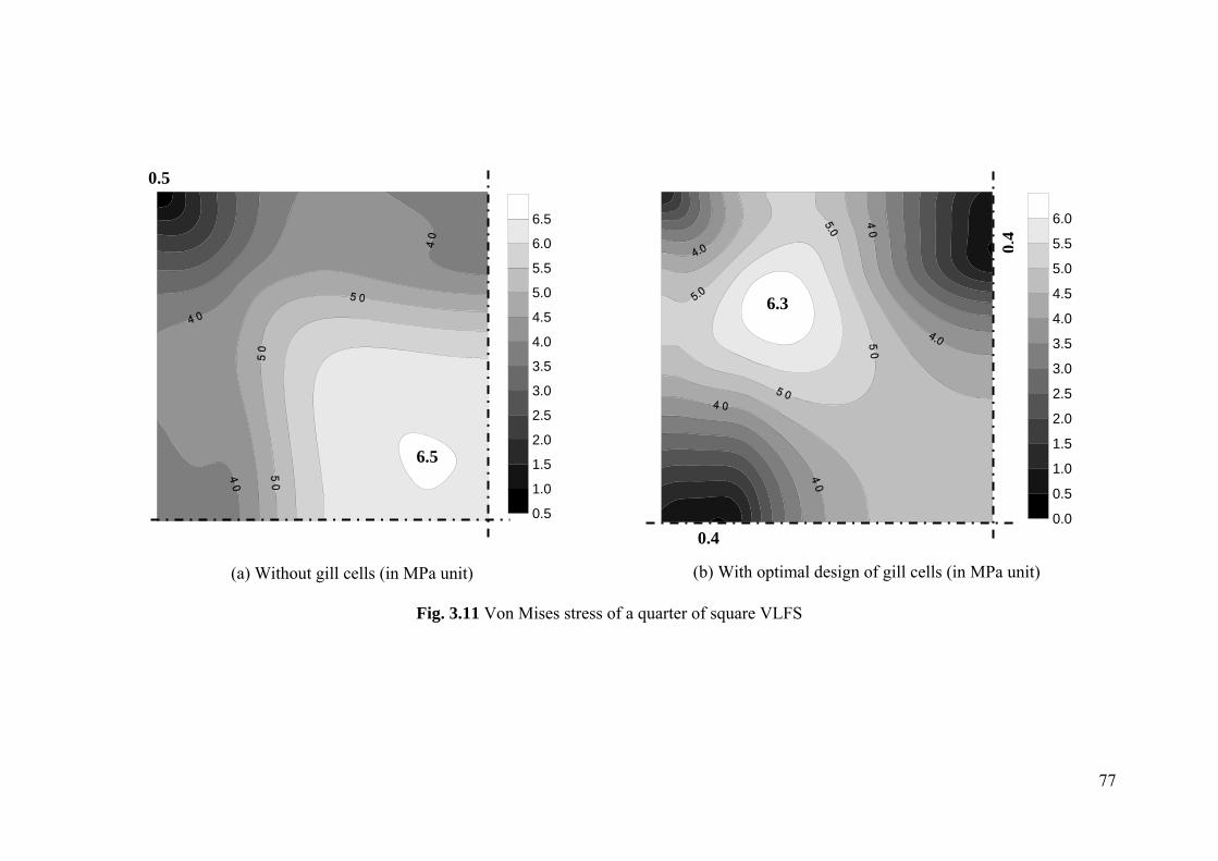
77
0.5
1.0
1.5
2.0
2.5
3.0
3.5
4.0
4.5
5.0
5.5
6.0
6.5
(a) Without gill cells (in MPa unit)
0.0
0.5
1.0
1.5
2.0
2.5
3.0
3.5
4.0
4.5
5.0
5.5
6.0
(b) With optimal design of gill cells (in MPa unit)
Fig. 3.11 Von Mises stress of a quarter of square VLFS
6.3
0.4
0.4
6.5
0.5
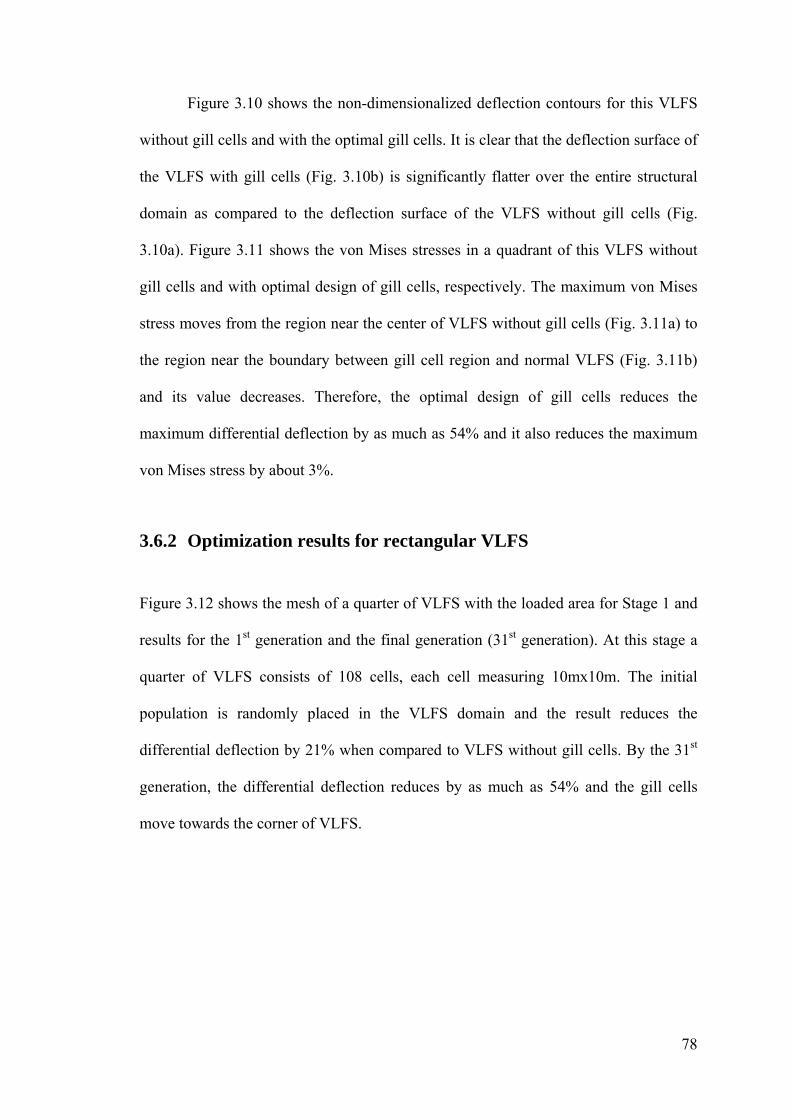
78
Figure 3.10 shows the non-dimensionalized deflection contours for this VLFS
without gill cells and with the optimal gill cells. It is clear that the deflection surface of
the VLFS with gill cells (Fig. 3.10b) is significantly flatter over the entire structural
domain as compared to the deflection surface of the VLFS without gill cells (Fig.
3.10a). Figure 3.11 shows the von Mises stresses in a quadrant of this VLFS without
gill cells and with optimal design of gill cells, respectively. The maximum von Mises
stress moves from the region near the center of VLFS without gill cells (Fig. 3.11a) to
the region near the boundary between gill cell region and normal VLFS (Fig. 3.11b)
and its value decreases. Therefore, the optimal design of gill cells reduces the
maximum differential deflection by as much as 54% and it also reduces the maximum
von Mises stress by about 3%.
3.6.2 Optimization results for rectangular VLFS
Figure 3.12 shows the mesh of a quarter of VLFS with the loaded area for Stage 1 and
results for the 1st generation and the final generation (31st generation). At this stage a
quarter of VLFS consists of 108 cells, each cell measuring 10mx10m. The initial
population is randomly placed in the VLFS domain and the result reduces the
differential deflection by 21% when compared to VLFS without gill cells. By the 31st
generation, the differential deflection reduces by as much as 54% and the gill cells
move towards the corner of VLFS.

79
area lqLoaded
120m90m30m
30m
60m90
m
Mesh and loading area
1st generation 0 0.7924w wΔ Δ =
31st generation 0 0.4551w wΔ Δ =
Fig. 3.12 Stage 1 for rectangular VLFS
For Stage 2, we have a quarter of VLFS comprising 432 cells, each cell
measuring 5mx5m. Figure 3.13 shows the decrease in the maximum differential
deflection and patterns of gill cells at various generations for the first 60 generations.
The initial population of gill cells is randomly placed in the bounded corner region as
shown in Fig. 3.13 just like in the case of the square VLFS, but with the bounded
longer side on the longer edge of the VLFS. After the optimization process, the gill
cells coalesce around the corner of VLFS in a right-angled triangular shape. After
examining the gill cells locations and based on practical considerations, we consider
three design options (locations and number) of gill cells as shown in Fig. 3.14. The
ratios of the maximum differential deflection of VLFS with gill cells and without gill
cells are 0.4468, 0.4767, and 0.4839 for Option 1, Option 2, and Option 3, respectively.
These ratios clearly show the effectiveness of gill cells in reducing the maximum
differential deflection. Even when the gill cell layout is very simple, the reduction in
the maximum differential deflection can be more than 51%. Option 1 has the minimum
differential deflections among the three options and this differential deflection is also
very close to the value obtained in the 60th generation. Therefore, we choose Option 1

80
as the optimal design of gill cells for the rectangular VLFS. Figure 3.15 shows the
non-dimensionalized deflection contour in this VLFS with the optimal gill cells and
without gill cells. VLFS with the optimal design of gill cells (Fig. 3.15b) is
significantly flatter over the entire structural domain as compared to the VLFS without
gill cells (Fig. 3.15a). Figure 3.16 shows the von Mises stresses in a quadrant of this
VLFS with optimal design of gill cells and without gill cells, respectively. VLFS with
optimal design of gill cells (Fig. 3.16b) has smaller maximum von Mises stress than
that of the VLFS without gill cells (Fig. 3.16a). Therefore, in this example, the optimal
design of gill cells reduces the maximum differential deflection by about 55% as well
as the maximum von Mises stress by 24%.
Initial generation 0 0.5402w wΔ Δ =
10th generation
0 0.4747w wΔ Δ =
20th generation
0 0.461w wΔ Δ =
30th generation 0 0.4532w wΔ Δ =
50th generation 0 0.4432w wΔ Δ =
60th generation 0 0.4429w wΔ Δ =
Fig. 3.13 Layouts of gill cells in a quadrant of rectangular VLFS for various
generations in Stage 2

81
Lc
Lc30m180m
240m30m
30m
120m
30m
180m
Option 1 0 0.4468w wΔ Δ =
Lc
Lc30m
240m180m30m
30m
120m
180m
30m
Option 2 0 0.4767w wΔ Δ =
Lc
Lc30m180m30m
240m
30m
120m
30m
180m
Option 3 0 0.4839w wΔ Δ =
Fig. 3.14 Rectangular VLFS with some possible optimal designs of gill cells

82
0.200.250.300.350.400.450.500.550.600.650.700.750.800.850.900.951.001.051.10
(a) Without gill cells
0.65
0.70
0.75
0.80
0.85
0.90
0.95
1.00
1.05
1.10
(b) With optimal design of gill cells
Fig. 3.15 Nondimensionalized deflection contour w in rectangular VLFS
1.133
0.222 0.222
0.222 0.222
1.101
0.694 0.694
0.694 0.694
83
0.00.51.01.52.02.53.03.54.04.55.05.56.06.57.07.5
(a) Without gill cells (in MPa unit)
0.0
0.5
1.0
1.5
2.0
2.5
3.0
3.5
4.0
4.5
5.0
5.5
6.0
(b) With optimal design of gill cells (in MPa unit)
Fig. 3.16 Von Mises stress of a quarter of rectangular VLFS
0.47 0.26
6.027.94

84
3.6.3 Optimization results for I-shaped VLFS
Figure 3.17 shows the mesh of a quarter of VLFS with the loaded area for Stage 1 and
the results for the 1st generation and 33rd generation (final generation). At this stage, a
quarter of VLFS consists of 117 cells, each cell measuring 10mx10m. The initial
population is randomly placed in the VLFS domain and the result reduces the
differential deflection by 16%. By the 33rd generation, the differential deflection has
been reduced by 66% and the gill cells move towards the corner of VLFS.
area lqLoading
60m30m30m120m
30m
90m12
0m
Mesh and loading area
1st generation 0 0.8421w wΔ Δ =
33rd generation 0 0.3422w wΔ Δ =
Fig. 3.17 Stage 1 for I-shaped VLFS
For Stage 2, we have 468 cells in the quarter of VLFS. The decrease in the
maximum differential deflection and patterns of gill cells at various generations for the
first 100 generations are shown in Fig. 3.18. The initial population is randomly placed
in the bold bound region which covers the gill cell locations found in the 33rd
generation of Stage 1.

85
Initial generation 0 0.5297w wΔ Δ =
10th generation
0 0.3759w wΔ Δ =
20th generation
0 0.3465w wΔ Δ =
40th generation 0 0.3431w wΔ Δ =
70th generation
0 0.3421w wΔ Δ =
100th generation 0 0.3411w wΔ Δ =
Fig. 3.18 Layouts of gill cells in quadrant of I-shaped VLFS for various generations
in Stage 2
After examining the trend of movement of gill cells in the optimization
exercise (Fig. 3.18), we consider three practical design options for the locations and
number of gill cells as shown in Fig. 3.19. The ratios of the maximum differential
deflection for VLFS with and without gill cells are 0.3440, 0.3658, and 0.3909 for
Option 1, Option 2, and Option 3, respectively. These ratios clearly demonstrate the
effectiveness of gill cells in reducing the differential deflection. Even with a simple gill
cell layout, the reduction can be more than 60%. We choose Option 1 as the optimal
design of gill cells because it has the minimum differential deflection among the three
options and this differential deflection is also very close to the value obtained in the
100th generation of the optimization program. Figure 3.20 shows the non-

86
dimesionalized deflection contour in this VLFS with the optimal gill cells and without
gill cells. VLFS with the optimal design of gill cells is significantly flatter as compared
to the VLFS without gill cells. Figure 3.21 shows the von Mises stresses in a quadrant
of this VLFS with optimal design of gill cells and without gill cells, respectively. The
maximum von Mises stress moves from the center of VLFS without gill cells (Fig.
3.21a) to the reentrance corner of VLFS (Fig. 3.21b) and its values increases. In this
example, the optimal design of gill cells reduces the maximum differential deflection
by about 66%. However, it increases the maximum von Mises stress by 26% near the
re-entrant corner. This is caused by the sudden change in the bending curvature at the
re-entrant corner. By placing suitable steel reinforcements in the re-entrant, one can
accommodate for these von Mises stresses. From this result, in order to avoid
increasing the von Mises stresses in VLFS with gill cells, one can provide smooth
transition at these re-entrant corners.

87
Lc
Lc
30m
180m
30m
240m
30m 30m 120m 30m 30m240m
Option 1 0 0.3440w wΔ Δ =
Lc
Lc
30m
180m
30m
240m
30m 30m 120m 30m 30m240m
Option 2 0 0.3658w wΔ Δ =
Lc
Lc
30m
180m
30m
240m
30m30m120m30m30m240m
Option 3 0 0.3909w wΔ Δ =
Fig. 3.19 I-shaped VLFS with some possible optimal designs of gill cells

88
0.00
0.10
0.20
0.30
0.40
0.50
0.60
0.70
0.80
0.90
1.00
1.10
(a) without gill cells
0.70
0.73
0.75
0.80
0.85
0.90
0.95
1.00
1.05
(b) with optimal design of gill cells
Fig. 3.20 Nondimesionalized deflection contour w in I-shaped VLFS
1.08 1.13
0.72
0.72
0.08 0.08
0.08 0.08

89
0
1
2
3
4
5
6
7
(a) without gill cells (in MPa unit)
0
1
2
3
4
5
6
7
8
9
(b) with optimal design of gill cells (in MPa unit)
Fig. 3.21 Von Mises stress of a quarter of the I-shaped VLFS
9.95
0.11 0.02
7.89
90
3.7 Concluding remarks
In this chapter, a FE computer code employing Mindlin plate element is developed for
the bending analysis of VLFS. Genetic algorithms, fully coded in MATLAB, are
employed to seek the optimal layout (number and locations) of gill cells in VLFS. The
modeling and optimization technique are illustrated with examples of various shapes
of VLFSs such as square, rectangular and I-shape. The results of these example VLFSs
show that, with the optimal design of gill cells, the differential deflections in square,
rectangular and I-shaped VLFSs can be significantly reduced by about 55%, 54%, and
66%, respectively. The VLFSs deflection shapes become significantly flatter over the
entire of VLFS domains. Furthermore, with optimal gill cells, the von Mises stresses
are also reduced in the square and rectangular VLFS. However for I-shaped VLFS, the
maximum von Mises stress increases at the re-entrant corners. Therefore, we can
conclude that gill cells may be applied to VLFS to minimize the differential deflection.
But for the VLFS with re-entrant corners, reinforcement must be introduced since the
von Mises stress may increase in these regions. Other way to avoid increasing the von
Mises stresses in VLFS with gill cells, one can provide smooth transition at these re-
entrant corners. The FEM model and optimization technique can be applied to any
shape of floating structure under any loading configuration so as to minimize the
differential deflection.
91
CHAPTER 4
MINIMIZING HEAVING MOTION OF
CIRCULAR VLFS USING SUBMERGED PLATE
4.1 Introduction
A submerged horizontal single plate attached to the fore-end of a rectangular VLFS
was proposed and investigated experimentally by Ohta et al. (1999). The experimental
results showed that the displacement of a VLFS model with this anti-motion device is
reduced significantly not only at the edges but also in the inner domain of the floating
structure. They suggested that by using this anti-motion device, it would be possible to
eliminate the construction of breakwaters in a bay where waves are comparatively
small. Utsunomiya et al. (2000) made an attempt to reproduce these experimental
results by analysis. The comparison of the analytical results with the experimental
results has shown that their simple model can reproduce the reduction effect only
qualitatively. A more precise model considering rigorously the configuration of the
submerged horizontal plate within the framework of linear potential theory is
constructed in a study by Watanabe et al. (2003a) and they validated their model with
experimental results.
In this chapter, we investigate the effectiveness of a submerged horizontal
annular plate strip as an anti-heaving device in reducing vertical deflections and stress-
resultants of a circular VLFS. In earlier studies of such an anti-motion device attached
to the fore-end of a rectangular VLFS, the vertical displacement at the aft-end is noted

Minimizing Heaving Motion of Circular VLFS using Submerged Plate
92
to be still relatively large. Therefore, we will analyze a circular VLFS with this device
attached around its edge. We formulate the diffraction and radiation potentials using
the eigen-function expansion method which was originally proposed by Stoker (1957)
for the estimation of the elastic floating breakwater. This method has been widely
applied in many studies such as the study of elastic deformation of ice floes (e.g.,
Evans and Davies 1968, Fox and Squire 1990, Meylan and Squire 1993) and the study
of the oblique incidence of surface waves onto an infinitely long platform (e.g.,
Sturova 1998, Kim and Ertekin 1998). Takagi et al. (2000) and Watanabe et al. (2003)
also applied this method to analyze the box-shaped and single plate anti-motion device
to a rectangular VLFS. We will compare obtained results of a VLFS with submerged
horizontal plate anti-motion device with the results of the VLFS alone to show the
efficiency of this device in a circular VLFS in reducing vertical deflection and stress-
resultants.
4.2 Problem definition
The fluid-structure system and the cylindrical coordinates system are shown in Fig. 4.1.
In this figure, region 1 is within VLFS and the submerged plate. Region 2 is beneath
the submerged plate. Region 3 is outside VLFS and the submerged plate. Region 4 is
outside VLFS and on top of the submerged plate. Region 5 is confined from the top of
the submerged plate to the bottom of VLFS. The origin of the coordinates system is on
the flat sea-bed and the z- axis is pointing upwards. The undisturbed free surface is on
the plane z H= , and the sea-bed is assumed to be flat at 0=z . The floating, flat,
circular plate has a radius of R and a uniform thickness h . The zero draft is assumed
for simplifying the fluid-domain analysis. The horizontal annular plate strip of width
2a is attached around the edge of the VLFS at a submerged level z = d. The sinusoidal

Minimizing Heaving Motion of Circular VLFS using Submerged Plate
93
plane wave is assumed to be incident to VLFS at 0=θ . The problem at hand is to
determine the effectiveness of the horizontal annular plate strip in reducing the
deflections and stress-resultants of the uniform circular plate under the wave action.
x
r,
θ
y
χ
z
R
2a1
5 4
2
3z=d
z=0
h
z=H
Sea bed
Incident Wave
Fig. 4.1 Geometry of uniform circular VLFS and coordinate system
4.3 Basic assumptions, equations and boundary conditions for
circular VLFS
The hydroelastic analysis is performed in the frequency domain. Considering time-
harmonic motions with the complex time dependence tie ϖ being applied to all first-
order oscillatory quantities, where i represents the imaginary unit, ϖ the angular
frequency of the wave and t the time, the complex velocity potential ),,( zr θφ is
governed by the Laplace’s equation:

Minimizing Heaving Motion of Circular VLFS using Submerged Plate
94
0),,(2 =∇ zr θφ (4.1)
in the fluid domain. The potential must satisfy the following boundary conditions on
the free surface, on the sea-bed, on the wetted bottom surface of the floating circular
body and on the submerged annular plate:
),,(),,( 2
zrgz
zr θφϖθφ =∂
∂ on , z H r R= > (4.2)
0),,( =∂
∂z
zr θφ on 0=z (4.3)
),(),,( θϖθφ rwiz
zr =∂
∂ on , z H r R= ≤ (4.4)
( , , ) ( , )r z i w Rz
φ θ ϖ θ∂ =∂
on , z d R a r R a= − ≤ ≤ + (4.5)
where ),( θrw is the vertical complex displacement of the VLFS, and g the
gravitational acceleration.
The radiation condition for the scattering and radiation potential is also applied
at infinity.
0)()(lim =⎥⎦⎤
⎢⎣⎡ −+
∂−∂
∞→ II
rik
rr φφφφ as ∞→r (4.6)
where r is the radial coordinate measured from the center of the circular VLFS, k the
wave number, and Iφ the potential representing the undisturbed incident wave:
1/ 20
00
cosh ( ) ( ) coscosh cosh
ikx nI n n
n
igAMigA kz e Z z i J kr nkH kH
φ ε θϖ ϖ
∞
=
= = ∑ (4.7)
Minimizing Heaving Motion of Circular VLFS using Submerged Plate
95
where 0 1, 2 ( 1)n nε ε= = ≥ ; A the amplitude of the incident wave; nJ the Bessel
function of the first kind of order n ; and
2
tanhk kHg
ϖ= (4.8)
1/ 20 0( ) coshZ z M kz−= (4.9)
01 sinh 212 2
kHMkH
⎛ ⎞= +⎜ ⎟⎝ ⎠
(4.10)
By assuming the circular VLFS to be an elastic, isotropic, shear deformable
plate, the motion of the floating circular body is governed by the following Mindlin
plate equations (Mindlin 1951):
012
1 32 =+−
−+
∂∂
+∂
∂rr
rrr hQr
MMMrr
M ψγϖθ
θθ (4.11)
012
21 32 =+−+
∂∂
+∂
∂θθ
θθθ ψγϖθ
hQr
MMrr
M rrr (4.12)
),(1 2 θγϖθ
θ rphwr
QQrr
Q rr =++∂
∂+
∂∂ (4.13)
where w is the modal displacement, θψψ ,r are the modal rotations. The bending
moments θMM r , , twisting moment θrM , and the shear forces θQQr , can be
calculated from the following relations:
⎭⎬⎫
⎩⎨⎧
⎟⎠⎞
⎜⎝⎛
∂∂++
∂∂=
θψψνψ θ
rr
r rrDM (4.14)
⎭⎬⎫
⎩⎨⎧
⎟⎠⎞
⎜⎝⎛
∂∂
++∂
∂=
θψψψν θ
θ rr
rrDM 1 (4.15)
Minimizing Heaving Motion of Circular VLFS using Submerged Plate
96
( )⎭⎬⎫
⎩⎨⎧
⎟⎠⎞
⎜⎝⎛ −
∂∂
+∂
∂−= θ
θθ ψ
θψψν r
r rrDM 112
(4.16)
r S rwQ K Ghr
ψ ∂⎛ ⎞= +⎜ ⎟∂⎝ ⎠ (4.17)
1S
wQ K Ghrθ θψ
θ∂⎛ ⎞= +⎜ ⎟∂⎝ ⎠
(4.18)
in which D is the plate rigidity, γ the mass per unit area of the plate, ν the Poisson
ratio, SK the Mindlin shear correction factor, and ),( θrp the fluid pressure on the
bottom surface of the plate.
The pressure ),( θrp is related to the velocity potential ),,( zr θφ by
Utsunomiya et al. (1998):
( , ) ( , , ) ( , )wp r i r H gw rθ ρϖφ θ γ θ= − − (4.19)
where wgγ is the hydrostatic restoring force factor and wγ the density of the water.
The floating body is free to move in the vertical direction along its edges and at
its free edges, the bending moment, twisting moment and shear force must vanish, i.e.
0 ,0 ,0 === rrr QMM θ (4.20)
4.4 Modal expansion of motion
The fluid-structure interaction is decomposed into the hydrodynamic problem in terms
of the velocity potential and the mechanical problem for the vibration of the circular
plate, the motion of the plate is expanded by the modal functions which consist of the
product of the natural dry modes of circular Mindlin plates with free edges.
Minimizing Heaving Motion of Circular VLFS using Submerged Plate
97
Irie et al. (1980) derived the exact vibration solutions for circular Mindlin plates
with free edges. The natural frequency parameters 2 hRDγξ ω= may be calculated
from setting the determinant of the matrix for the following homogeneous system of
equations to zero, i.e.
{ }11 12 13 1
21 22 23 2
31 32 33 3
k k k Ak k k Ak k k A
⎡ ⎤ ⎧ ⎫⎪ ⎪⎢ ⎥ =⎨ ⎬⎢ ⎥⎪ ⎪⎢ ⎥⎣ ⎦ ⎩ ⎭
0 (4.21)
where the elements of the matrix are given by:
)]()()()[1( 12
1'
1''
111 δνδνδσ nnn JnJJk −+−= (4.22)
)]()()[1(2 22'
222 δδσ nn JJnk −−−= (4.23)
)]()()[1( 33'
13 δδν nn JJnk −−= (4.24)
)]()()[1(2 11'
121 δδσ nn JJnk −−−= (4.25)
)]()()[1(2 22'
222 δδσ nn JJnk −−−= (4.26)
'' ' 223 3 3 3( ) ( ) ( )n n nk J J n J= − δ + δ − δ (4.27)
)( 1'
131 δσ nJk = (4.28)
)( 2'
232 δσ nJk = (4.29)
)( 333 δnnJk = (4.30)
and
( )2 2 2 22 1 2 1
1 2 22 2 23
2
( , ) 2( , ), 16(1 )
12
δ δ δ δσ σδ ντ ξ ν κ
τ
= =−⎡ ⎤−−⎢ ⎥
⎣ ⎦
(4.31)
Minimizing Heaving Motion of Circular VLFS using Submerged Plate
98
22 2 2 2 22 2
1 2 2 2 2
4, 2 12 6(1 ) 12 6(1 )
ξ τ τ τ τδ δν κ ν κ ξ
⎡ ⎤⎛ ⎞⎢ ⎥= + ± − +⎜ ⎟⎢ ⎥− −⎝ ⎠⎣ ⎦ (4.32)
( )2 2 2
23 2
2 6(1 )1 12
τ ξ ν κδν τ
⎡ ⎤−= −⎢ ⎥− ⎣ ⎦ (4.33)
Rh=τ (4.34)
The modal displacement w and the modal rotations θψψ ,r are given by:
21 Θ+Θ=w (4.35)
∂θ∂
∂∂σ
∂∂σψ 32
21
11)1()1(
Θ+
Θ−+
Θ−=
rrrr (4.36)
rrr ∂∂
∂θ∂σ
∂θ∂σψ θ
322
11
1)1(1)1(Θ
−Θ
−+Θ
−= (4.37)
where
( ) θχ nRA n cos111 Δ=Θ (4.38)
( ) θχ nRA n cos222 Δ=Θ (4.39)
( ) θχ nRA n sin333 Δ=Θ (4.40)
in which Rr /=χ ; n ( ),...,1,0 N= is the number of nodal diameters in the vibration
mode; and
( ) 3,2,1,0Im0
2
2
=⎩⎨⎧
<≥
=Δ jifif
jj
jjj δδ
δδ (4.41a)
( ) ( )( ) 3,2,1,
00
2
2
=⎩⎨⎧
<Δ≥Δ
=Δ jifIifJ
Rjjn
jjnjn δχ
δχχ (4.41b)

Minimizing Heaving Motion of Circular VLFS using Submerged Plate
99
and )(•nJ and )(•nI are the first kind and the modified first kind Bessel functions of
order n.
By using the superposition of the natural dry modes and the two rigid-body
motions (heave and pitch), the final solution of the plate deflection is given by:
∑∑= =
++=N
n
M
snsns nrwwwrw
0 110100000 cos)(cos),( θζθζζθ (4.42)
∑∑= =
=N
n
M
snsrnsr nrr
0 1, cos)(),( θψζθψ (4.43)
∑∑= =
=N
n
M
snsns nrr
0 1, sin)(),( θψζθψ θθ (4.44)
where nsnsrnsw ,, , , θψψ describe the natural dry modes (mode shape of free vibration);
s the sequence number for a given n value (i.e. );,...,2,1 Ms = and
Rrww /2 , 2 1000 == (4.45)
Note that 00w represents the heaving motion while 10w the pitching motion. The
complex modal amplitudes nsζ are the unknowns which are to be determined. When
N and M equal to infinity, Eqs. (4.42) to (4.44) provide the exact solution of a circular
Mindlin plate.
4.5 Solutions for radiation potentials
The velocity potential φ is then decomposed into diffraction and radiation potentials
by using the same modal amplitudes as in Newman (1994)

Minimizing Heaving Motion of Circular VLFS using Submerged Plate
100
( ) ( ) ( )( )( )
0 0 0 0,11 2
, , , cos , cosN N M
Dn ns nsn n s n
s n
r z r z n i r z nφ θ φ θ ϖ ζ φ θ= = = =
= ≥
= +∑ ∑ ∑ (4.46)
The boundary conditions on the free surface and wetted bottom surface of the
floating body, i.e. Eqs. (4.4-4.5), are modified to
( ),0Dn r z
zφ∂
=∂
on , and , z d R a r R a z H r R= − ≤ ≤ + = ≤ (4.47)
( ) ( ),ns
ns
r zw R
zφ∂
=∂
on , z d R a r R a= − ≤ ≤ + (4.48)
( ) ( ),ns
ns
r zw r
zφ∂
=∂
on , z H r R= ≤ (4.49)
Referring to Hamamoto and Tanaka (1992), in which the general solution for
circular VLFS is shown, the general solution for the boundary value problems can be
derived for each region from 1 to 5 defined in Fig. 4.1 as follows:
( ) ( ) ( ) ( )( )( )
( ) ( )( )( )
( )( )
( )( ) ( ) ( )
11 1 1 1(1)
,0 0 , 11
21 01
,
/ cosh /2 /sinh /
nn j
ns ns ns j jj n j
Rn nj nj
ns n njj nj n nj nj
I rrr z C Z C ZR a I R a
J r R z Rw r J r R rdr
R J H R
γφ
γ
λ λλ
λ λ λ
∞
=
∞
= +
⎛ ⎞= + +⎜ ⎟−⎝ ⎠ −
⋅ ⋅
∑
∑ ∫
(4.50)
( ) ( ) ( ) ( ) ( ) ( ) ( )( )( )
( ) ( )( )( )
( )( )( )
( ) ( )( )( )
( )( )( )
( )( )( )( )( ) ( ) ( )( )
2
2 2 2 2 2 2 2,0 0 ,0 0 , 2
1
2
2 2, 22
1 1 1
0
,
/2
cosh //
sinh /
n nn j
ns ns ns ns j jj n j
n j n njns j j
j j nj n njn j
R anj
ns n njnj
I rr R ar z C Z D Z C ZR a r I R a
K r J r R aD Z
R a JK R a
z R aw R J r R a rdr
d R a
γφ
γ
γ λλ λγ
λλ
λ
∞
=
∞ ∞
= = +
+
−⎛ ⎞ ⎛ ⎞= + +⎜ ⎟ ⎜ ⎟+⎝ ⎠ ⎝ ⎠ +
++ + ⋅
+−
+⋅ +
+
∑
∑ ∑
∫
(4.51)

Minimizing Heaving Motion of Circular VLFS using Submerged Plate
101
( ) ( ) ( )( ) ( )( )
( ) ( ) ( )( )( ) ( )
( )( )( ) ( )( )
( )2 3 3
03 3 3 3 3,0 0 ,2 3 3
10
,n n j
ns ns ns j jjn n j
H k r K k rr z C Z C Z
H k R a K k R aφ
∞
=
= ++ +
∑ (4.52)
If ( ) ( )2nj 1R a gω λ+ < , ( ) ( )( )2
njatanhb R a gω λ= +
( ) ( ) ( )( )( )
( ) ( )( )( ) ( )
( )( )( )( )
( )
( )( )( )
( ) ( )( )( ) ( )
( )( )( )( )
( )
( )( )( )
( )( ) ( )( )( ) ( )( )
( ) ( )( )
4 40 04 4 4 4 4
,0 0 ,0 04 40 0
4 44 4 4 4, ,4 4
1 1
21 1
0
,
/ cosh /2sinh /
/
n nns ns ns
n n
n j n j
ns j j ns j jj jn j n j
n nj nj
j nj n nj nj
R a
ns n nj
J k r Y k rr z C Z D Z
J k R a Y k R
I k r K k rC Z D Z
I k R a K k R
J r R a z H R a bR a J d H R a b
w R J r R a rdr
φ
λ λλ λ λ
λ
∞ ∞
= =
∞
= +
+
= + ++
+ ++
+ − + +⋅
+ − + +
⋅ +
∑ ∑
∑
∫
(4.53a)
If ( ) ( )2nj 1R a gω λ+ ≥ , ( ) ( )( )( )2
njatanhb g R aλ ω= +
( ) ( ) ( )( )( )
( ) ( )( )( ) ( )
( )( )( )( )
( )
( )( )( )
( ) ( )( )( ) ( )
( )( )( )( )
( )
( )( )( )
( )( ) ( )( )( ) ( )( )
( ) ( )( )
4 40 04 4 4 4 4
,0 0 ,0 04 40 0
4 44 4 4 4, ,4 4
1 1
21 1
0
,
/ sinh /2cosh /
/
n nns ns ns
n n
n j n j
ns j j ns j jj jn j n j
n nj nj
j nj n nj nj
R a
ns n nj
J k r Y k rr z C Z D Z
J k R a Y k R
I k r K k rC Z D Z
I k R a K k R
J r R a z H R a bR a J d H R a b
w R J r R a rdr
φ
λ λλ λ λ
λ
∞ ∞
= =
∞
= +
+
= + ++
+ ++
+ − + +⋅
+ − + +
⋅ +
∑ ∑
∑
∫
(4.53b)

Minimizing Heaving Motion of Circular VLFS using Submerged Plate
102
( ) ( ) ( ) ( ) ( ) ( ) ( )( )( )( )( )
( )
( )( )( )
( ) ( )( )( )
( )( )( )
( )( ) ( )( )( ) ( )( ) ( ) ( )( )
( )
5
5 5 5 5 5 5 5,0 0 ,0 0 , 5
1
5
5 5, 25
1 1 1
0
,
/2
cosh //
sinh /
/2
n nn j
ns ns ns ns j jj n j
n j n njns j j
j j nj n njn j
R anj
ns n njnj
n nj
nj
I rr R ar z C Z D Z C ZR r I R
K r J r R aD Z
R a JK R a
z H R aw R J r R a rdr
d H R a
J r RR
γφ
γ
γ λλ λγ
λλ
λ
λλ
∞
=
∞ ∞
= = +
+
−⎛ ⎞ ⎛ ⎞= + +⎜ ⎟ ⎜ ⎟⎝ ⎠ ⎝ ⎠
++ + ⋅
+−
− +⋅ + +
− +
∑
∑ ∑
∫
( )( )( )
( )( ) ( ) ( )21 01
cosh //
sinh /
Rnj
ns n njj n nj nj
z d Rw r J r R rdr
J H d R
λλ
λ λ
∞
= +
−⋅ ⋅
−∑ ∫
(4.54)
( )2 ,n nH I and nK represent Hankel function of the second-kind, modified Bessel
function of the first and second-kind of order n , respectively; njλ is the j -th positive
root of the equation ( ) 0n njJ λ = ; ( ),
ins jC and ( )
,i
ns jD are the unknown coefficients to be
determined; and
( )( )1
1
1
cos( )jj
j
zZ
Nγ
= (4.55)
( )( )2
2
2
cos( )jj
j
zZ
Nγ
= (4.56)
( )( )3
3
3
cos( )jj
j
k zZ
N= (4.57)
( )( ) ( )4
4
4
cos( )jj
j
k z dZ
N−
= (4.58)
( )( ) ( )( )5
5
5
cos jj
j
z dZ
N
γ −= (4.59)
( )1j
jHπγ = (4.60)

Minimizing Heaving Motion of Circular VLFS using Submerged Plate
103
( )2j
jdπγ = (4.61)
( )5j
jH d
πγ =−
(4.62)
( ) ( )( )2
3 3tanj jk k Hg
ϖ− = ( )( )3 0; 1jk j> ≥ (4.63)
( ) ( ) ( )( )2
4 4tanj jk k H dg
ϖ− − = ( )( )4 0; 1jk j> ≥ (4.64)
( ) ( ) ( )2
4 4tanhk k H dg
ϖ− = (4.65)
1 j jN H ε= (4.66)
2 j jN d ε= (4.67)
( )5 j jN H d ε= − (4.68)
( )( )( )
3
3 3
sin 2
2 4j
jj
k HHNk
= + ( )1j ≥ (4.69)
( ) ( )( )( )
4
4 4
sin 2
2 4j
jj
k H dH dNk
−−= + ( )1j ≥ (4.70)
Note that when j = 0, we have ( )30k ik= − and Eq. (4.63) reduces to the dispersion
relation given in Eq. (4.8), ( ) ( )4 40k ik= − and Eq. (4.64) reduces to the dispersion
relation given in Eq. (4.65). The situation where 1≥j implies that we are referring to
evanescent wave.
In order to ensure the formulation of independent equations, the following
orthogonal relationships are satisfied:

Minimizing Heaving Motion of Circular VLFS using Submerged Plate
104
( ) ( ) ( ) ( ) ( ) ( )
( ) ( ) ( ) ( )
1 1 2 2 3 3
0 0 0
4 4 5 5
H d H
i j i j i j
H H
i j i j ijd d
Z Z dz Z Z dz Z Z dz
Z Z dz Z Z dz δ
= = =
= =
∫ ∫ ∫∫ ∫
(4.71)
where ⎩⎨⎧
≠== )( 0
)( 1jiji
ijδ (4.72)
The continuity of the potential nsφ on the boundary between regions 2 and 3
( )r R a= + can be expressed as:
( ) ( ) ( ) ( ) ( ) ( ) ( ) ( )
( )( ) ( )( )( ) ( )( )
( )
3 3 2 2 2 2 2 2, ,0 0 ,0 0 ,
0 1
2
2 2, 2
1
n
ns j j ns ns ns j jj j
n jns j j
j n j
R aC Z C Z D Z C ZR a
K R aD Z
K R a
γ
γ
∞ ∞
= =
∞
=
−⎛ ⎞= + +⎜ ⎟+⎝ ⎠
++
−
∑ ∑
∑ (4.73)
By applying ( )2
0
d
lZ dz∫ to both sides of the foregoing equation, we obtain:
( ) ( ) ( )
( )
( ) ( ) ( )
( ) ( )( ) ( )( )( ) ( )( ) ( )2 3
2 2,0 ,0
3 2 32, 0
0 2 2, , 2
for 0
for 0lj
n
ns nsd
ns j l jn lj
Z ns l ns ln l
R aC D lR a
C Z Z dz K R aC D l
K R a
γ
γ−
∞
=
⎧ −⎛ ⎞+ =⎪ ⎜ ⎟+⎝ ⎠⎪⎪= ⎨ +⎪ + >⎪ −⎪⎩
∑ ∫ (4.74)
Similarly, by considering the continuity of the potential nsφ on the boundary
between regions 4 and 3 ( )r R a= + and applying ( )4H
ldZ dz∫ to both sides of the
continuity equation, we obtain:

Minimizing Heaving Motion of Circular VLFS using Submerged Plate
105
( ) ( ) ( )
( )
( ) ( )( ) ( )( )
( )( ) ( )
( ) ( )( ) ( )( )
( )( ) ( )4 3
404 4
,0 ,0 403 4 3
, 404 4, , 4
for 0
for 0lj
n
ns ns
nH
ns j l jdj
n lZ
ns l ns l
n l
Y k R aC D l
Y k RC Z Z dz
K k R aC D l
K k R−
∞
=
⎧ +⎪ + =⎪⎪= ⎨
+⎪+ >⎪
⎪⎩
∑ ∫ (4.75)
The continuity of the horizontal velocity ns rφ∂ ∂ on the boundary of the regions
2, 4 and 3 ( )r R a= + with ( ) ( )2nj 1R a gω λ+ < gives
( )( ) ( ) ( ) ( )( )
( ) ( ) ( )( )( ) ( )
( ) ( ) ( )( )( ) ( )( )
( )
( )
( )( ) ( ) ( )
( )( ) ( )
( ) ( ) ( )( )( ) ( )( )
( )
( )( )( )
( )( )( )( ) ( ) ( )( )
3 2 ' 3 3 3'0 03 3 3 3
,0 0 ,2 3 310
2 2'2 2 2 2 2 2,0 0 ,0 0 ,1 2
1
'
2 201
cosh /2 /sinh /
n j n jns ns j j
jn n j
nj n j
ns ns ns j jnj n j
n nj njns n nj
n nj nj
k H k R a k K k R aC Z C Z
H k R a K k R a
I R an R anC Z D Z C ZR a R a I R a
J z R aw R J r R a rdr
J d R aR a
γ γ
γ
λ λλ
λ λ
∞
=
∞
+=
+
+ ++ =
+ +
+−− +
+ + +
++ ⋅ ⋅ +
++
∑
∑
( )( ) ( ) ( )( )
( ) ( )( )( ) ( )
( )( ) ( ) ( )( )
( ) ( )( )( ) ( )
( ) ( ) ( )( )( ) ( )( )
( )
( )( )( )
( ) ( )( )( ) ( )( )
( ) ( )( )
1
2 2'2 2, 2
1
4 4 4 4' '0 04 4 4 4
,0 0 ,4 410
'
2 21 1
0
for 0
cosh /2sinh /
/
R a
j
j n jns j j
j n j
n j n j
ns ns j jjn n j
n nj nj
j n nj nj
R a
ns n nj
K R aD Z z d
K R a
k J k R a k I k R aC Z C Z
J k R a I k R a
J z H R a b
J d H R a bR a
w R J r R a rdr D
γ γ
γ
λ λλ λ
λ
+∞
=
∞
=
∞
=
∞
= +
+
++ ≤ <
−
+ ++ +
+ +
− + +⋅ ⋅
− + ++
+ +
∑ ∫
∑
∑
∑
∫ ( )( ) ( ) ( )( )
( )( )( )
( )( ) ( ) ( )( )
( )( )( ) ( )
4 4'0 04 4
,0 040
4 4'4 4, 4
1for
n
nsn
j n jns j j
j n j
k Y k R aZ
Y k R
k K k R aD Z d z H
K k R
∞
=
⎧⎪⎪⎪⎪⎪⎪⎪⎪⎪⎪⎪⎪⎪⎨⎪⎪⎪⎪⎪⎪
+⎪+⎪
⎪⎪⎪ +⎪ ≤ ≤⎪⎩∑
(4.76)
Applying ( )3
0
H
lZ dz∫ to both sides of the above equation, we obtain:

Minimizing Heaving Motion of Circular VLFS using Submerged Plate
106
( )( ) ( ) ( ) ( )( )
( ) ( ) ( )( ) ( )
( )( ) ( ) ( )( )
( ) ( )( ) ( )
( )
( )( ) ( ) ( )
( )( )
( )( ) ( ) ( )( )
( ) ( )( )( ) ( )
( ) ( ) ( )( )( ) ( )( )
( )
( )
3 2 ' 30 03
,0 2 30 2 2 3 2 2 3
,0 0 ,0 013 3'3, 3
2 2 2 2' '2 2 3 2 2 3, ,2 2
1 1
2
for 0
for 0
2
n
nsn
n
ns l ns ln
l n lns l
n l
j n j j n jns j jl ns j jl
j jn j n j
k H k R aC l
H k R a n R anC Z D ZR a R ak K k R a
C lK k R a
I R a K R aC Z D Z
I R a K R a
R a
γ γ γ γ
γ γ
− −+
∞ ∞− −
= =
⎫+⎪=⎪+ −⎪ = −⎬ + ++ ⎪
> ⎪+ ⎪⎭
+ ++ + +
+ −
+
∑ ∑
( )( )
( )( )( )( )
( )
( ) ( )( ) ( )( ) ( ) ( )( )
( ) ( )( )( )
( )( ) ( ) ( )( )
( )( )( ) ( )
( ) ( ) ( )( )( ) ( )( )
( )
( )( ) ( ) ( )( )
'3
2 01 1
4 4'0 04 4 3
,0 040 0
4 4 4 4' '0 04 4 3 4 4 3
,0 0 ,4 410
4 4'4,
cosh /
sinh /
/
dn nj njl
j n nj nj
R an
ns n nj ns l
n
n j n j
ns l ns j jljn n j
j n j
ns j
n j
J z R aZ dz
J d R a
k J k R aw R J r R a rdr C Z
J k R a
k Y k R a k I k R aD Z C Z
Y k R I k R a
k K k R aD
K k
λ λλ λ
λ
∞
= +
+−
∞− −
=
+⋅ ⋅
+
++ +
+
+ ++ +
+
++
∑ ∫
∫
∑
( )( )( )
( )( )( )
( ) ( )( )( ) ( )( )
( ) ( ) ( )( )
'4 3
2 241 1 1
3
0
2
cosh //
sinh /
n njjl
j j n nj
R aH nj
l ns n njdnj
JZ
JR aR
z H R a bZ dz w R J r R a rdr
d H R a b
λλ
λλ
λ
∞ ∞−
= = +
+
+ ⋅+
− + +⋅ +
− + +
∑ ∑
∫ ∫(4.77a)
Similarly, considering the continuity of the horizontal velocity ns rφ∂ ∂ on the
boundary of the regions 2, 4 and 3 ( )r R a= + with ( ) ( )2nj 1R a gω λ+ ≥ , and
applying ( )3
0
H
lZ dz∫ to both sides of the continuity equation, we obtain:
Minimizing Heaving Motion of Circular VLFS using Submerged Plate
107
( )( ) ( ) ( ) ( )( )
( ) ( ) ( )( ) ( )
( )( ) ( ) ( )( )
( ) ( )( ) ( )
( )
( )( ) ( ) ( )
( )( )
( )( ) ( ) ( )( )
( ) ( )( )( ) ( )
( ) ( ) ( )( )( ) ( )( )
( )
( )
3 2 ' 30 03
,0 2 30 2 2 3 2 2 3
,0 0 ,0 013 3'3, 3
2 2 2 2' '2 2 3 2 2 3, ,2 2
1 1
2
for 0
for 0
2
n
nsn
n
ns l ns ln
l n lns l
n l
j n j j n jns j jl ns j jl
j jn j n j
k H k R aC l
H k R a n R anC Z D ZR a R ak K k R a
C lK k R a
I R a K R aC Z D Z
I R a K R a
R a
γ γ γ γ
γ γ
− −+
∞ ∞− −
= =
⎫+⎪=⎪+ −⎪ = −⎬ + ++ ⎪
> ⎪+ ⎪⎭
+ ++ + +
+ −
+
∑ ∑
( )( )
( )( )( )( )
( )
( ) ( )( ) ( )( ) ( ) ( )( )
( ) ( )( )( )
( )( ) ( ) ( )( )
( )( )( ) ( )
( ) ( ) ( )( )( ) ( )( )
( )
( )( ) ( ) ( )( )
'3
2 01 1
4 4'0 04 4 3
,0 040 0
4 4 4 4' '0 04 4 3 4 4 3
,0 0 ,4 410
4 4'4,
cosh /
sinh /
/
dn nj njl
j n nj nj
R an
ns n nj ns l
n
n j n j
ns l ns j jljn n j
j n j
ns j
n j
J z R aZ dz
J d R a
k J k R aw R J r R a rdr C Z
J k R a
k Y k R a k I k R aD Z C Z
Y k R I k R a
k K k R aD
K k
λ λλ λ
λ
∞
= +
+−
∞− −
=
+⋅ ⋅
+
++ +
+
+ ++ +
+
++
∑ ∫
∫
∑
( )( )( )
( )( )( )
( ) ( )( )( ) ( )( )
( ) ( ) ( )( )
'4 3
2 241 1 1
3
0
2
sinh //
cosh /
n njjl
j j n nj
R aH nj
l ns n njdnj
JZ
JR aR
z H R a bZ dz w R J r R a rdr
d H R a b
λλ
λλ
λ
∞ ∞−
= = +
+
+ ⋅+
− + +⋅ +
− + +
∑ ∑
∫ ∫(4.77b)
Similarly, considering the continuity of the potential nsφ on the boundary
between regions 2 and 1 (r = R-a), and applying ( )2
0
d
lZ dz∫ to both sides of the
continuity equation, we obtain:
Minimizing Heaving Motion of Circular VLFS using Submerged Plate
108
( )( )( )
( )( )
( ) ( ) ( )
( ) ( ) ( )
( )
( ) ( ) ( )
( )( ) ( )( )( ) ( )( )
( ) ( )
( )
2 1
22 0
1 01
2 2,0 ,0
1 2 12, 0
0 2 2, ,2
/ cosh /2 /sinh /
for 0
for 0
2
lj
Rdn nj nj
l ns n njj nj n nj nj
n
ns nsd
ns j l jn lj
Z ns l ns l
n l
n
nj
J R a R z RZ dz w r J r R rdr
R J H R
R aC D lR a
C Z Z dz I R aC D l
I R a
JR a
λ λλ
λ λ λ
γ
γ
λλ
−
∞
= +
∞
=
−⋅ ⋅
⎧ −⎛ ⎞ + =⎪ ⎜ ⎟+⎝ ⎠⎪⎪+ = ⎨ −⎪ + >⎪ +⎪⎩
++
∑ ∫ ∫
∑ ∫
( ) ( )( )( )
( )( )( )( )
( )
( ) ( )( )
22 0
1 1
0
/ cosh /
sinh /
/
dnj njl
j n nj nj
R a
ns n nj
R a R a z R aZ dz
J d R a
w R J r R a rdr
λλ λ
λ
∞
= +
+
− + +⋅ ⋅
+
+
∑ ∫
∫
(4.78)
Similarly, considering the continuity of the potential nsφ on the boundary
between regions 5 and 1 (r = R-a), and applying ( )5H
ldZ dz∫ to both sides of the
continuity equation, we obtain:
( )( )( )
( )( )
( ) ( ) ( )
( ) ( ) ( )
( )
( ) ( ) ( )
( )( ) ( )( )
( )( )( ) ( )
( )
5 1
52
1 01
5 5,0 ,0
1 5 15,
0 5 5, ,5
/ cosh /2 /sinh /
for 0
for 0
/2
lj
RHn nj nj
l ns n njdj nj n nj nj
n
ns nsH
ns j l jd n ljZ ns l ns l
n l
n nj
nj
J R a R z RZ dz w r J r R rdr
R J H R
R aC D lR
C Z Z dz I R aC D l
I R
J R aR
λ λλ
λ λ λ
γ
γ
λλ
−
∞
= +
∞
=
−⋅ ⋅
⎧ −⎛ ⎞ + =⎪ ⎜ ⎟⎝ ⎠⎪⎪+ = +⎨ −⎪ + >⎪
⎪⎩
−
∑ ∫ ∫
∑ ∫
( )( )
( )( )( )( )
( )
( ) ( ) ( )( ) ( )( )
( )( ) ( )( )( ) ( )( )
( ) ( ) ( )( )
52
1 1
210 1
5
0
cosh /
sinh /
/2/
cosh //
sinh /
H njld
j n nj nj
Rn nj
ns n njj nj n nj
R aH nj
l ns n njdnj
R z d RZ dz
J H d R
J R a R aw r J r R rdr
R a J
z H R aZ dz w R J r R a rdr
d H R a
λλ λ
λλ
λ λ
λλ
λ
∞
= +
∞
= +
+
−⋅ ⋅
−
− ++
+
− +⋅ ⋅ +
− +
∑ ∫
∑∫
∫ ∫
(4.79)
Minimizing Heaving Motion of Circular VLFS using Submerged Plate
109
The continuity of the horizontal velocity ns rφ∂ ∂ on the boundary of the regions
1, 2 and 5 ( )r R a= − , and the application of ( )1
0
H
lZ dz∫ yield:
( )
( )
( )( ) ( ) ( )( )
( ) ( )( ) ( )
( )( )( )
( )( )
( ) ( ) ( )
( ) ( )( )
( )( )
( ) ( )( ) ( ) ( )( )
( ) ( )( )
1,0
1 1'1
, 1
'1
2 2 01 01
2 2'1 22 2 1 2 1 2,0,0 0 0 , 2
for 0
for 0
/ cosh /2 /sinh /
ns
l n l
ns ln l
RHn nj nj
l ns n njj n nj nj
nj n jns
ns l l ns jnn j
nCl
R aI R a
C lI R a
J R a R z RZ dz w r J r R rdr
R J H R
I R anDn R aC Z Z C
R aR a I R a
γ γ
γ
λ λλ
λ λ
γ γ
γ
∞
= +
−− −
⎧=⎪
−⎪+⎨ −⎪ >⎪ −⎩
−⋅ =
−−− +
−+ +
∑ ∫ ∫
( )
( )( ) ( ) ( )( )
( ) ( )( )( )
( )( ) ( )( )
( )( )( )( )( )
( ) ( ) ( )( )
( ) ( )( )
( )( )
( ) ( )( ) ( ) ( )( )
( )
2 1
1
2 2' '2 2 1, 2 22
1 1 1
1
00
5 5'1 55 5 1 5 1 5,0,0 0 0 , 5
/2
cosh //
sinh /
jlj
j n j n njns j jl
j j n njn j
R ad nj
l ns n njnj
nj n jns
ns l l ns jnn j
Z
K R a J R a R aD Z
JR aK R a
z R aZ dz w R J r R a rdr
d R a
I R anDn R aC Z Z C
R aR I
γ γ λλγ
λλ
λ
γ γ
γ
∞−
=
∞ ∞−
= = +
+
−− −
+
− − ++
+−
+⋅ ⋅ + +
+
−−− +
−
∑
∑ ∑
∫ ∫
( )( )
( )( ) ( ) ( )( )
( ) ( )( )( )
( )( ) ( )( )
( )( ) ( )( )( ) ( )( )
( ) ( ) ( )( )
( )( )( )
( )( )( )( )
( )
5 1
1
5 5' '5 5 1, 2 25
1 1 1
1
0
'1
2 21 1
/2
cosh //
sinh /
/ cosh /2sinh /
jlj
j n j n njns j jl
j j n njn j
R aH nj
l ns n njdnj
n nj njld
j n nj nj
ZR
K R a J R a R aD Z
JR aK R a
z H R aZ dzw R J r R a rdr
d H R a
J R a R z d RZ dz
R J H d R
γ γ λλγ
λλ
λ
λ λλ λ
∞−
=
∞ ∞−
= = +
+
∞
= +
+
− − ++ ⋅
+−
− ++ +
− +
− −⋅
−
∑
∑ ∑
∫ ∫
∑ ( ) ( )0
/R
H
ns n njw r J r R rdrλ∫ ∫
(4.80)
The continuity of the potential nsφ on the boundary between regions 4 and 5
( )r R= in the case ( ) ( )2nj 1R a gω λ+ < , and the application of ( )4H
ldZ dz∫ yield:

Minimizing Heaving Motion of Circular VLFS using Submerged Plate
110
( )( )( )
( ) ( )( )( ) ( )
( )( )( )
( ) ( )( )( ) ( )
( )( )( )
( )( ) ( )( )( ) ( )( )
( )
( ) ( )( ) ( ) ( ) ( )
( )4 50
404 4
,0 ,040
44 4, ,4
42
1 1
5 4 5,0 0
0
for 0
for 0
/ cosh /2sinh /
/
l
nns ns
n
n l
ns l ns ln l
Hn nj nj
lj nj dn nj nj
R aH
ns n nj ns ld
Z
J k RC D l
J k R a
I k RC D l
I k R a
J R R a z H R a bZ dz
R a J d H R a b
w R J r R a rdr C Z Z dz
λ λλ λ λ
λ−
∞
= +
+
⎧⎪ + =⎪ +⎪ +⎨⎪
+ >⎪+⎪⎩
+ − + +⋅ ⋅
+ − + +
+ =
∑ ∫
∫ ∫
( ) ( ) ( )
( )
( ) ( ) ( )
( )
( )( )( )
( ) ( )( )( ) ( )
( )( )
( )( )( )
( ) ( )( )( ) ( )( )
( )
4 5 4 50
4 5
5 4 5 5 4 5,0 0 ,
1
5
5 4 5, 25
1 1 1
4
/2
cosh /
sinh /
l lj
lj
nH H
ns l ns j l jd dj
Z Z
Hn j n njns j l jd
j j nj n njn jZ
Hnj
ld nj
R aD Z Z dz C Z Z dzR
K R J R R aD Z Z dz
R a JK R a
z H R aZ dz
d H R a
γ λλ λγ
λλ
− −
−
∞
=
∞ ∞
= = +
+
−⎛ ⎞ + +⎜ ⎟⎝ ⎠
++
+−
− +⋅ ⋅
− +
∑∫ ∫
∑ ∑∫
∫ ( ) ( )( )0
/R a
ns n njw R J r R a rdrλ+
+∫ (4.81a)
In case ( ) ( )2nj 1R a gω λ+ ≥ , we have

Minimizing Heaving Motion of Circular VLFS using Submerged Plate
111
( )( )( )
( ) ( )( )( ) ( )
( )( )( )
( ) ( )( )( ) ( )
( )( )( )
( )( ) ( )( )( ) ( )( )
( )
( ) ( )( ) ( ) ( ) ( )
( )4 50
404 4
,0 ,040
44 4, ,4
42
1 1
5 4 5,0 0
0
for 0
for 0
/ sinh /2cosh /
/
l
nns ns
n
n l
ns l ns ln l
Hn nj nj
lj nj dn nj nj
R aH
ns n nj ns ld
Z
J k RC D l
J k R a
I k RC D l
I k R a
J R R a z H R a bZ dz
R a J d H R a b
w R J r R a rdr C Z Z dz
λ λλ λ λ
λ−
∞
= +
+
⎧⎪ + =⎪ +⎪ +⎨⎪
+ >⎪+⎪⎩
+ − + +⋅ ⋅
+ − + +
+ =
∑ ∫
∫ ∫
( ) ( ) ( )
( )
( ) ( ) ( )
( )
( )( )( )
( ) ( )( )( ) ( )
( )( )
( )( )( )
( ) ( )( )( ) ( )( )
( )
4 5 4 50
4 5
5 4 5 5 4 5,0 0 ,
1
5
5 4 5, 25
1 1 1
4
/2
cosh /
sinh /
l lj
lj
nH H
ns l ns j l jd dj
Z Z
Hn j n njns j l jd
j j nj n njn jZ
Hnj
ld nj
R aD Z Z dz C Z Z dzR
K R J R R aD Z Z dz
R a JK R a
z H R aZ dz
d H R a
γ λλ λγ
λλ
− −
−
∞
=
∞ ∞
= = +
+
−⎛ ⎞ + +⎜ ⎟⎝ ⎠
++
+−
− +⋅ ⋅
− +
∑∫ ∫
∑ ∑∫
∫ ( ) ( )( )0
/R a
ns n njw R J r R a rdrλ+
+∫ (4.81b)
The continuity of the horizontal velocity ns rφ∂ ∂ on the boundary between
regions 4 and 5 ( )r R= in the case ( ) ( )2nj 1R a gω λ+ < , and the application
( )4H
ldZ dz∫ yield:
Minimizing Heaving Motion of Circular VLFS using Submerged Plate
112
( )( ) ( )( )
( ) ( )( )( )
( ) ( )( )( )( ) ( )
( )( ) ( )( )
( ) ( )( )( )
( ) ( )( )( )( ) ( )
( )( )( )
( )( ) ( )( )( ) ( )( )
( )
( )
4 4 4 4' '0 0 0 04 4
,0 ,04 40 0
4 4 4 4' '4 4, ,4 4
'4
2 21 1
for 0
for 0
/ cosh /2sinh /
/
n n
ns nsn n
l n l l n l
ns l ns l
n l n l
Hn nj njld
j n nj nj
ns n nj
k J k R k Y k RC D l
J k R a Y k R
k I k R k K k RC D l
I k R a K k R
J R R a z H R a bZ dz
J d H R a bR a
w R J r
λ λλ λ
λ
∞
= +
⎧⎪ + =⎪ +⎪ +⎨⎪
+ >⎪+⎪⎩
+ − + +⋅ ⋅
− + ++∑ ∫
( )( ) ( ) ( ) ( ) ( ) ( )
( )( ) ( )( )
( )( )( ) ( )
( ) ( )( )( ) ( )( )
( )
( )( )
( )( )( )( )
( ) ( ) ( )
( )
5 4 5 5 4 5,0 0 ,0 01
0
5 5 5 5' '5 4 5 5 4 5, ,5 5
1 1
'4
2 21 01
2
cosh /2 /sinh /
2
nR a
ns l ns ln
j n j j n j
ns j lj ns j ljj jn j n j
RHn nj nj
l ns n njdj n nj nj
n R anR a rdr C Z D ZR R
I R K RC Z D Z
I R K R a
J z d RZ dz w r J r R rdr
R J H d R
J
R a
γ γ γ γ
γ γ
λ λλ
λ λ
+− −
+
∞ ∞− −
= =
∞
= +
−+ = −
+ + +−
−⋅ ⋅
−
++
∫
∑ ∑
∑ ∫ ∫
( )( )( )
( ) ( )( )( ) ( )( )
( )
( ) ( )( )
'4
21 1
0
/ cosh /
sinh /
/
Hn nj njld
j n nj nj
R a
ns n nj
R R a z H R aZ dz
J d H R a
w R J r R a rdr
λ λλ λ
λ
∞
= +
+
+ − +⋅ ⋅
− +
+
∑ ∫
∫ (4.82a)
In the case ( ) ( )2nj 1R a gω λ+ ≥ , we have
Minimizing Heaving Motion of Circular VLFS using Submerged Plate
113
( )( ) ( )( )
( ) ( )( )( )
( ) ( )( )( )( ) ( )
( )( ) ( )( )
( ) ( )( )( )
( ) ( )( )( )( ) ( )
( )( )( )
( )( ) ( )( )( ) ( )( )
( )
( )
4 4 4 4' '0 0 0 04 4
,0 ,04 40 0
4 4 4 4' '4 4, ,4 4
'4
2 21 1
for 0
for 0
/ sinh /2cosh /
/
n n
ns nsn n
l n l l n l
ns l ns l
n l n l
Hn nj njld
j n nj nj
ns n nj
k J k R k Y k RC D l
J k R a Y k R
k I k R k K k RC D l
I k R a K k R
J R R a z H R a bZ dz
J d H R a bR a
w R J r
λ λλ λ
λ
∞
= +
⎧⎪ + =⎪ +⎪ +⎨⎪
+ >⎪+⎪⎩
+ − + +⋅ ⋅
− + ++∑ ∫
( )( ) ( ) ( ) ( ) ( ) ( )
( )( ) ( )( )
( )( )( ) ( )
( ) ( )( )( ) ( )( )
( )
( )( )
( )( )( )( )
( ) ( ) ( )
( )
5 4 5 5 4 5,0 0 ,0 01
0
5 5 5 5' '5 4 5 5 4 5, ,5 5
1 1
'4
2 21 01
2
cosh /2 /sinh /
2
nR a
ns l ns ln
j n j j n j
ns j lj ns j ljj jn j n j
RHn nj nj
l ns n njdj n nj nj
n R anR a rdr C Z D ZR R
I R K RC Z D Z
I R K R a
J z d RZ dz w r J r R rdr
R J H d R
J
R a
γ γ γ γ
γ γ
λ λλ
λ λ
+− −
+
∞ ∞− −
= =
∞
= +
−+ = −
+ + +−
−⋅ ⋅
−
++
∫
∑ ∑
∑ ∫ ∫
( )( )( )
( ) ( )( )( ) ( )( )
( )
( ) ( )( )
'4
21 1
0
/ cosh /
sinh /
/
Hn nj njld
j n nj nj
R a
ns n nj
R R a z H R aZ dz
J d H R a
w R J r R a rdr
λ λλ λ
λ
∞
= +
+
+ − +⋅ ⋅
− +
+
∑ ∫
∫ (4.82b)
With the above procedures, the continuity equations for both potential and
velocities have been satisfied. By solving the system of 8 sets of linear equations, we
can determine the 8 sets of unknown coefficients
( ) ( ) ( ) ( ) ( ) ( ) ( )( )1 2 2 4 4 5 53, , , , , , , ,, , , , , , ,ns j ns j ns j ns j ns j ns j ns j ns jC C D C C D C D .
4.6 Solutions for diffraction potentials
The general solution for diffraction potential can be obtained by the following
equations:
( ) ( ) ( ) ( ) ( )( )( )
( ) ( )( )( ) ( )
1
1 1 1 1(1),0 0 , 1
1
,n
n j
Dn n n j jj n j
I rrr z C Z z C Z zR a I R a
γφ
γ
∞
=
⎛ ⎞= +⎜ ⎟−⎝ ⎠ −∑ (4.83)

Minimizing Heaving Motion of Circular VLFS using Submerged Plate
114
( ) ( ) ( ) ( ) ( ) ( )
( )( )( )
( ) ( )( )( ) ( )
( )( )( ) ( )( )
( )
2 2 2 2 2,0 0 ,0 0
2 22 2 2 2, ,2 2
1 1
,n n
Dn n n
n j n j
n j j n j jj jn j n j
r R ar z C Z D ZR a r
I r K rC Z D Z
I R a K R a
φ
γ γ
γ γ
∞ ∞
= =
−⎛ ⎞ ⎛ ⎞= + +⎜ ⎟ ⎜ ⎟+⎝ ⎠ ⎝ ⎠
++ −
∑ ∑ (4.84)
( ) ( ) ( )( ) ( )( )
( ) ( ) ( )( )( ) ( ) ( )
( )( )( ) ( )( )
( ) ( )
( ) ( ) ( )
2 3 303 3 3 3 3
,0 0 ,2 3 310
30
,n n j
Dn n n j jjn n j
In
H k r K k rr z C Z z C Z z
H k R a K k R a
r Z z H
φ
φ
∞
=
= ++ +
+
∑ (4.85)
( ) ( ) ( )( )( )
( ) ( )( )( ) ( )
( )( )( )( )
( )
( )( )( )
( ) ( )( )( ) ( )
( )( )( )( )
( )
4 40 04 4 4 4 4
,0 0 ,0 04 40 0
4 44 4 4 4, ,4 4
1 1
,n n
Dn n n
n n
n j n j
n j j n j jj jn j n j
J k r Y k rr z C Z D Z
J k R a Y k R
I k r K k rC Z D Z
I k R a K k R
φ
∞ ∞
= =
= + ++
++
∑ ∑ (4.86)
( ) ( ) ( ) ( ) ( ) ( )
( )( )( )( )( )
( ) ( )( )( )
( ) ( )( )( )
5 5 5 5 5,0 0 ,0 0
5 55 5 5 5, ,5 5
1 1
,n n
Dn n n
n j n j
n j j n j jj jn j n j
r R ar z C Z D ZR r
I r K rC Z D Z
I R K R a
φ
γ γ
γ γ
∞ ∞
= =
−⎛ ⎞ ⎛ ⎞= + +⎜ ⎟ ⎜ ⎟⎝ ⎠ ⎝ ⎠
+−
∑ ∑ (4.87)
where
1/ 20 ( )
coshn
In n nigAM i J kr
kHφ ε
ϖ= (4.88)
8 sets of unknown coefficients ( ) ( ) ( ) ( ) ( ) ( ) ( )( )1 2 2 4 4 5 53, , , , , , , ,, , , , , , ,n j n j n j n j n j n j n j n jC C D C C D C D can be
determined by applying the continuity equations for the potential and velocities on the
boundaries of each region with the same procedure as shown in part 4.5.
4.7 Equation of motion in modal coordinates
In order to derive the equations of motion in modal coordinates, we consider the
kinetic energy T , the strain energy U and the energy associated with the pressure V

Minimizing Heaving Motion of Circular VLFS using Submerged Plate
115
( )22 2 2 2 2
0 0
12 12
R
m rhT h w rdrd
π
θγ ϖ ψ ψ θ⎧ ⎫= + +⎨ ⎬
⎩ ⎭∫ ∫ (4.89)
222
20 0
2 2 2
2 2
1 1{ [ 22
1 1] [ ]}2
Rr r
r r
rS r
U Dr r r r
w wr K Gh r rdrdr r r r
πθ θ
θθ θ
ψ ψψ ψν ψ ψθ θ
ψ ψν ψ ψ ψ θθ θ
∂ ∂∂ ∂ ⎛ ⎞ ⎛ ⎞⎛ ⎞= + ⋅ + + + +⎜ ⎟ ⎜ ⎟ ⎜ ⎟∂ ∂ ∂ ∂⎝ ⎠ ⎝ ⎠ ⎝ ⎠
∂ ∂− ∂ ∂⎛ ⎞ ⎛ ⎞ ⎛ ⎞⋅ − − + + + +⎜ ⎟ ⎜ ⎟⎜ ⎟∂ ∂ ∂ ∂⎝ ⎠ ⎝ ⎠⎝ ⎠
∫ ∫ (4.90)
( ) ( )
( ){ ( ) ( ) }2 21 5
0 0 0
2 2 22 5 4
0 0 0
( , ) ( , )
( , ) ( , ) ( , )
R a R
R a
R a R R a
RR a R a R
V p r wrdrd p r wrdrd
p r drd p r drd p r drd w
π π
π π π
θ θ θ θ
θ θ θ θ θ θ
−
−
+ +
− −
= − − −
⎡ ⎤− +⎢ ⎥⎣ ⎦
∫ ∫ ∫ ∫
∫ ∫ ∫ ∫ ∫ ∫ (4.91)
The Hamilton’s principle can be given as:
0=++− VUT δδδ (4.92)
By substituting ,w rψ and θψ which are represented by Eqs. (4.42)-(4.44), and
applying the Rayleigh-Ritz method (i.e. integration can be approximated by a linear
combination of elements), we obtain:

Minimizing Heaving Motion of Circular VLFS using Submerged Plate
116
( )2
,,2, , , ,
0( 0,1) 0 01( 2
,,, , , ,
,, , , , ,2 2
{ } { [12
( ) ( )
1 1( ) ( ) (2
R RMr npr ns
ns m ns np r ns r np ns nps ns n
r npr nsnp r np ns r ns
nsns r ns np r np ns
hh w w rdr Dr r
n nr r r r
n n rr r
θ θ
θ θ
θθ θ θ
ψψζ γ ϖ ψ ψ ψ ψ
ψψν νψ ψ ψ ψ
ψνψ ψ ψ ψ ψ
= == ≥
∂⎡ ∂− + + + ⋅⎢ ∂ ∂⎣
∂∂+ ⋅ + + +
∂ ∂∂−+ + ⋅ + + −
∑ ∫ ∫
( )
( ) ( )
,
,, , , ,
12, ,2
0
5 22 2,
0
)
( )] [( ) ( )
1 ( )( )]} ] ( , )
( , ) ( ,
r ns
np npnsnp r np S r ns r np
R a
ns ns np np w ns np
R R
w ns np w ns np w np R nsR a
nr
wwr n K Ghr r r
nw r nw r rdr r H w rdrr
r H w rdr g w w rdr w r d
θθ
θ θ
ψ
ψψ ψ ψ ψ
ψ ψ γ ϖ φ
γ ϖ φ γ γ ϖ φ
−
−
+∂
∂ ∂∂⋅ − + + + ⋅ +∂ ∂ ∂
+ − + − + −
− + −
∫
∫ ∫
( ) ( )
( ) ( ) ( )
( ) ( )
5 42 2, ,
1 5 2,
0
5 4, ,
)
( , ) ( , )
( , ) ( , ) ( , )
( , ) ( , )
R a
R a
R R a
w np R ns w np R nsR a R
R a R R a
w Dn np w Dn np w np R DnR a R a
R R
w np R Dn w np R DnR a R
rdr
w r d rdr w r d rdr
i r H w rdr i r H w rdr i w r d rdr
i w r d rdr i w r d rdr
γ ϖ φ γ ϖ φ
γ ϖ φ γ ϖ φ γ ϖ φ
γ ϖ φ γ ϖ φ
+
−
+
−
− +
− −
+
−
+
⎤+ ⎥
⎦
= − − −
+ +
∫
∫ ∫
∫ ∫ ∫
∫a
∫
(4.93)
In view of the fact that normal modes satisfy Eqs. (4.11)-(4.18) and Eq. (4.20) , Eq.
(4.93) can be simplified to:
( )
( ) ( ) ( ) ( )
( )
12 2 2 2 2
0( 0,1) 01( 2)
5 2 5 4,
1
0 0
{ [ ( , )
( , ) ( ( , ) ( , ) ( , ) )]
} ( , )
R aM
ns m ps ns m ps w ns nps ns n
R R a R R a
ns np np R ns ns nsR a R a R a R
R R
w ns np w Dn np
hR hR r H w rdr
r H w rdr w r d rdr r d rdr r d rdr
g w w rdr i r H w rdr
ζ ϖ γ δ ϖ γ δ ϖ γ φ
φ φ φ φ
γ γ ϖ φ
−
= == ≥
+ +
− − −
−
− + − +
+ − −
+ = −
∑ ∫
∫ ∫ ∫ ∫
∫ ( )
( ) ( ) ( )
5
2 5 4,
( , )
( , ) ( , ) ( , )
a R
Dn npR a
R a R R a
np R Dn Dn DnR a R a R
r H w rdr
w r d rdr r d rdr r d rdr
φ
φ φ φ
−
+ +
− −
⎡+⎢
⎣⎤⎛ ⎞
+ − − ⎥⎜ ⎟⎥⎠⎝ ⎦
∫ ∫
∫ ∫ ∫
(4.94)
where the normalization of the modal vectors is made such that

Minimizing Heaving Motion of Circular VLFS using Submerged Plate
117
( ) ps
R
npnsnprnsrnpns Rrdrww δψψψψτθθ
2
0,,,,
2
12=
⎭⎬⎫
⎩⎨⎧
++∫ (4.95)
and nsϖ represents the natural frequency. Equation (4.94) may be represented in a non-
dimensional form by:
( )
( ) ( ) ( ) ( )
( )
2 3 212 2
0( 0,1) 01( 2)
5 2 5 4,
1
0
{ [ ( , )
( , ) ( ( , ) ( , ) ( , ) )]
} [ ( , )
R aMm
ns ps ns ps ns nps n ws n
R R a R R a
ns np np R ns ns nsR a R a R a R
R
ns np Dn np
R S R r H w rdrg g
r H w rdr w r d rdr r d rdr r d rdr
iw w rdr r H w rdg
γϖ ϖζ τ δ λ δ φγ
φ φ φ φ
ϖ φ
−
= == ≥
+ +
− − −
⎛ ⎞− + −⎜ ⎟
⎝ ⎠
+ + − −
+ = −
∑ ∫
∫ ∫ ∫ ∫
∫ ( )
( ) ( ) ( )
5
0
2 5 4,
( , )
( ( , ) ( , ) ( , ) )]
R a R
Dn npR a
R a R R a
np R Dn Dn DnR a R a R
r r H w rdr
w r d rdr r d rdr r d rdr
φ
φ φ φ
−
−
+ +
− −
+
+ − −
∫ ∫
∫ ∫ ∫
(4.96)
where 4/( ), ,wS D gR h R r Rγ τ χ= = = . Note that Eq. (4.96) can be solved separately
for each n (number of nodal diameters or Fourier modes). Also, the frequency
parameters nsλ and the corresponding mode shapes nsw are available in the literature
(e.g. Wang et al. 2004).
4.8 Results and discussions
Consider the circular VLFS and sea state condition treated by Watanabe et al. (2006).
The circular VLFS has a radius R = 200m, thickness h = 2m, density ratio
0.25m wγ γ = , non-dimensional rigidity S = 0.000433, Poisson’s ratio 0.3υ = , and
shear correction factor SK = 5/6. It is assumed that the water depth H = 20m and the
incident wave length λ = 50m. For numerical calculation, we also consider the number
of nodal diameters N = 14, the number of sequence M = 5 for given N as recommended
by Watanabe et al. (2006). In their study, they used the truncation number for infinite

Minimizing Heaving Motion of Circular VLFS using Submerged Plate
118
sums Γ =20. However, for the circular VLFS with an attached submerged annular
plate considered herein, the truncation number Γ may not be the same and it needs to
be established from a convergence study on the results.
In order to study the sensitivity of the width of the submerged horizontal plate
on the hydroelastic response of the VLFS, we analyze the circular VLFS without and
with a submerged horizontal annular plate having various widths ranging from 2m to
10m (a = 1~5m) and positioned at a depth d = 15m. The convergence check for the
truncation number Γ is done for two cases such as a VLFS with the smallest and
largest widths of the submerged annular plate. The convergence studies in terms of the
truncation of infinite sums for these two cases are shown in Figs. 4.2 and 4.3,
respectively, for Γ = 20, 40 and 60. It can be seen clearly that Γ = 40 will suffice for
converged results. So we have chosen the truncation number Γ = 40 for the subsequent
calculations. Figures 4.4 to 4.7 show the deflections and stress-resultants of a VLFS
without and with the submerged annular plate having various widths ranging from 2m
to 10m (a = 1~5m) and positioned at a depth d = 15m. We can see that as the width of
the submerged plate increases from 2m to 8m, the deflection and stress-resultants in
the VLFS decrease as compared with its counterpart without an attached submerged
plate. However when the width of the plate increases to 10m, the deflection and the
twisting moment near the fore end of the VLFS increase. From these results, the
effectiveness of the submerged horizontal plate in reducing the deflection and stress-
resultants is shown to be significant when the plate is not too wide. The submerged
annular plate with 8m width gives the best reduction.

Minimizing Heaving Motion of Circular VLFS using Submerged Plate
119
Fig. 4.2 Nondimensionalized deflection amplitude for a circular VLFS with 2m width submerged plate
Fig. 4.3 Nondimensionalized deflection amplitude for a circular VLFS with 10m width submerged plate
Incoming wave
Incoming wave

Minimizing Heaving Motion of Circular VLFS using Submerged Plate
120
Fig. 4.4 Nondimensionalized deflection amplitude of a circular VLFS without and with submerged plate of various widths
Fig. 4.5 Nondimensionalized bending moment amplitude of a circular VLFS without and with submerged plate of various widths
Incoming wave
Incoming wave
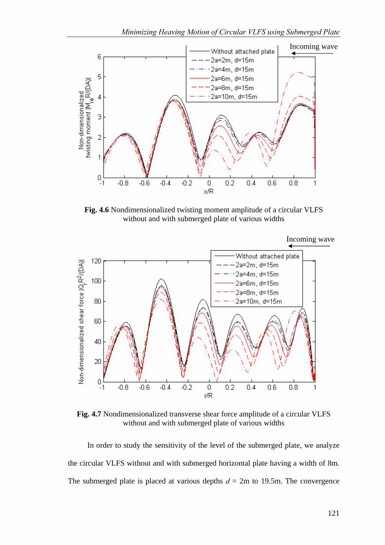
Minimizing Heaving Motion of Circular VLFS using Submerged Plate
121
Fig. 4.6 Nondimensionalized twisting moment amplitude of a circular VLFS without and with submerged plate of various widths
Fig. 4.7 Nondimensionalized transverse shear force amplitude of a circular VLFS without and with submerged plate of various widths
In order to study the sensitivity of the level of the submerged plate, we analyze
the circular VLFS without and with submerged horizontal plate having a width of 8m.
The submerged plate is placed at various depths d = 2m to 19.5m. The convergence
Incoming wave
Incoming wave

Minimizing Heaving Motion of Circular VLFS using Submerged Plate
122
studies for the required truncation number Γ are done for two cases, i.e. VLFS with
the submerged plate placed at the highest and lowest levels. The convergence
characteristics in terms of the truncation of infinite sums for these two cases are shown
in Fig. 4.8 and 4.9, respectively. It can be seen that Γ = 40 will suffice for converged
results for the case d = 19.5m whereas Γ = 60 is necessary for the case d = 2m. So we
have chosen the truncation number Γ = 60 for all calculations in this section. Figures
4.10 to 4.13 show the deflections and stress-resultants. Note that the free-edge
boundary conditions for the stress-resultants (Figs. 4.5 to 4.7 and 4.11 to 4.13) are
exactly satisfied because of the employment of the analytical Mindlin plate solutions.
It is generally difficult to observe the satisfaction of the natural boundary conditions
when using numerical methods based on the work-energy approach (see Wang et al.
2004 for a discussion on this matter). As the submerged plate moves nearer to the
bottom surface of the VLFS, its effectiveness becomes more apparent. However when
it moves too close to the VLFS (as the case for d = 19.5m), the motion of VLFS is
magnified near the fore-end. It may be due to the fact that the incoming wave makes
the submerged plate vibrate more and this motion gets transferred to the fore-end of
VLFS. We can see that the submerged annular plate with an 8m width and placed at d
= 18m seems to give the best reduction.

Minimizing Heaving Motion of Circular VLFS using Submerged Plate
123
-1 -0.8 -0.6 -0.4 -0.2 0 0.2 0.4 0.6 0.8 10
0.05
0.1
0.15
0.2
0.25
0.3
0.35
0.4
x/R
Non
-dim
ensi
onal
ized
def
lect
ion
|w(x
)/A|
Γ = 20Γ = 40Γ = 60Γ = 80
Fig. 4.8 Nondimensionalized deflection amplitude for a circular VLFS
with 8m width submerged plate at level d = 2m
Fig. 4.9 Nondimensionalized deflection amplitude for a circular VLFS with 8m width submerged plate at level d = 19.5m
Incoming wave
Incoming wave

Minimizing Heaving Motion of Circular VLFS using Submerged Plate
124
-1 -0.8 -0.6 -0.4 -0.2 0 0.2 0.4 0.6 0.8 10
0.05
0.1
0.15
0.2
0.25
0.3
0.35
0.4
x/R
Non
-dim
ensi
onal
ized
def
lect
ion
|w(x
)/A|
Without attached plate2a=8m, d=2m2a=8m, d=4m2a=8m, d=8m2a=8m, d=12m2a=8m, d=16m2a=8m, d=18m2a=8m, d=19.5m
Fig. 4.10 Nondimensionalized deflection amplitude of a circular VLFS without and with submerged plate at various depths
-1 -0.8 -0.6 -0.4 -0.2 0 0.2 0.4 0.6 0.8 10
5
10
15
20
x/R
Non
-dim
ensi
onal
ized
ra
dial
ben
ding
mom
ent |
MrR
/(DA
)|
Without attached plate2a=8m, d=2m2a=8m, d=4m2a=8m, d=8m2a=8m, d=12m2a=8m, d=16m2a=8m, d=18m2a=8m, d=19.5m
Fig. 4.11 Nondimensionalized bending moment amplitude of a circular VLFS without and with submerged plate at various depths
Incoming wave
Incoming wave
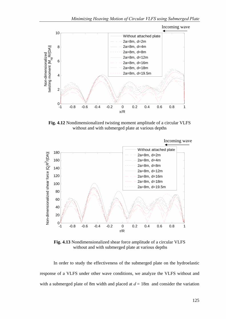
Minimizing Heaving Motion of Circular VLFS using Submerged Plate
125
-1 -0.8 -0.6 -0.4 -0.2 0 0.2 0.4 0.6 0.8 10
2
4
6
8
10
x/R
Non
-dim
ensi
onal
ized
tw
istin
g m
omen
t |M
r θR
/(DA
)|
Without attached plate2a=8m, d=2m2a=8m, d=4m2a=8m, d=8m2a=8m, d=12m2a=8m, d=16m2a=8m, d=18m2a=8m, d=19.5m
Fig. 4.12 Nondimensionalized twisting moment amplitude of a circular VLFS without and with submerged plate at various depths
-1 -0.8 -0.6 -0.4 -0.2 0 0.2 0.4 0.6 0.8 10
20
40
60
80
100
120
140
160
180
r/R
Non
-dim
ensi
onal
ized
she
ar fo
rce
|QrR
2 /(DA
)|
Without attached plate2a=8m, d=2m2a=8m, d=4m2a=8m, d=8m2a=8m, d=12m2a=8m, d=16m2a=8m, d=18m2a=8m, d=19.5m
Fig. 4.13 Nondimensionalized shear force amplitude of a circular VLFS without and with submerged plate at various depths
In order to study the effectiveness of the submerged plate on the hydroelastic
response of a VLFS under other wave conditions, we analyze the VLFS without and
with a submerged plate of 8m width and placed at d = 18m and consider the variation
Incoming wave
Incoming wave

Minimizing Heaving Motion of Circular VLFS using Submerged Plate
126
of wavelengths λ from R/25 to infinity (R/λ -> 0). The convergence behaviors of the
results in terms of the truncation of infinite sums for VLFS without and with
submerged plate are shown in Fig. 4.14 and 4.15, respectively. In both cases, shorter
waves require larger truncation numbers for convergence. It can be seen that Γ = 40 is
adequate for converged results of the basic VLFS while Γ = 60 is necessary for
converged results of VLFS with a submerged plate.
Figures 4.16 to 4.18 show the vertical deflections at the fore-end, mid-position
and back-end of the VLFS without and with horizontal submerged annular plate of 8m
width and placed at d = 18m as a function of R/λ. As it can be seen from these figures,
the effect of the submerged annular plate in reducing the hydroelastic response is
clearly observed.
Fig. 4.14 Nondimensionalized deflection amplitude for a basic circular VLFS at fore-end
Incoming wave

Minimizing Heaving Motion of Circular VLFS using Submerged Plate
127
0 5 10 15 20 250
0.2
0.4
0.6
0.8
1
1.2
1.4
R/λ
Non
-dim
ensi
onal
ized
def
lect
ion
|w(x
)/A|
Γ = 40Γ = 60
Γ = 80
Fig. 4.15 Nondimensionalized deflection amplitude for a circular VLFS with submerged plate at fore-end
Fig. 4.16 Nondimensionalized deflection amplitude of a circular VLFS at fore-end
Incoming wave
Incoming wave

Minimizing Heaving Motion of Circular VLFS using Submerged Plate
128
Fig. 4.17 Nondimensionalized deflection amplitude of a circular VLFS at mid-position
Fig. 4.18 Nondimensionalized deflection amplitude of a circular VLFS at back-end
4.9 Concluding remarks
In this chapter, the hydroelastic problem of a circular VLFS with a submerged
horizontal annular plate strip attached to its perimeter is analyzed in an exact manner
Incoming wave
Incoming wave

Minimizing Heaving Motion of Circular VLFS using Submerged Plate
129
for both the structure part and the fluid part. Although the formulations are given in
explicit formula, we have truncated the infinite sums. However, by using a suitable
truncation number Γ, one may still obtain very accurate converged results. The
significant reduction effect of the response with the attachment of the horizontal
submerged annular plate has been confirmed by the analysis.
It is important to note that the Mindlin plate theory has been adopted instead of
the commonly used classical thin plate theory in order to obtain more accurate stress-
resultants. Therefore the presented accurate hydroelastic responses should be useful to
VLFS engineers as benchmark solutions for verification of the numerical programs
based on the boundary element method and the finite element method.
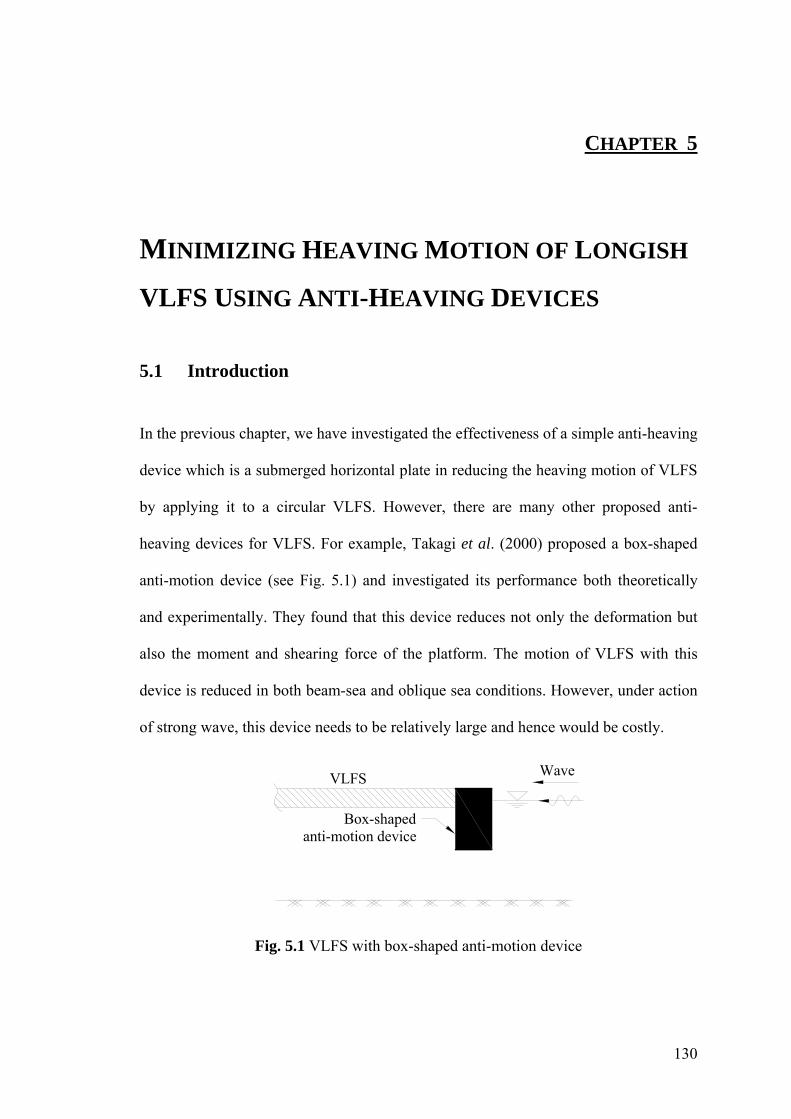
130
CHAPTER 5
MINIMIZING HEAVING MOTION OF LONGISH
VLFS USING ANTI-HEAVING DEVICES
5.1 Introduction
In the previous chapter, we have investigated the effectiveness of a simple anti-heaving
device which is a submerged horizontal plate in reducing the heaving motion of VLFS
by applying it to a circular VLFS. However, there are many other proposed anti-
heaving devices for VLFS. For example, Takagi et al. (2000) proposed a box-shaped
anti-motion device (see Fig. 5.1) and investigated its performance both theoretically
and experimentally. They found that this device reduces not only the deformation but
also the moment and shearing force of the platform. The motion of VLFS with this
device is reduced in both beam-sea and oblique sea conditions. However, under action
of strong wave, this device needs to be relatively large and hence would be costly.
WaveVLFS
Box-shaped anti-motion device
Fig. 5.1 VLFS with box-shaped anti-motion device

131
VLFS Wave
Submerged vertical plate anti-motion device
Fig. 5.2 VLFS with submerged vertical plate anti-motion device
Ohta et al. (1999), on the other hand, proposed a submerged vertical single
plate attached to the fore-end of VLFS as shown in Fig. 5.2. They investigated the
performance of such anti-motion device by conducting some experiments in a water
basin. The experimental results showed that the displacement of VLFS with this
submerged vertical plate is reduced significantly at the edges and in the inner parts as
well.
Continuing in this line of investigation, Ohta et al. (2002) considered other
anti-motion body forms such as an L-shaped plate, a reverse-L-shaped plate and a
beach-type plate (see Fig 5.3). They concluded that L-shaped plate is more effective
against long waves whereas beach-type plates and reverse-L-shaped plates are more
effective against short waves.
WaveVLFS
L-shaped plate anti-motion device
(a) VLFS with L-shaped plate anti-motion device
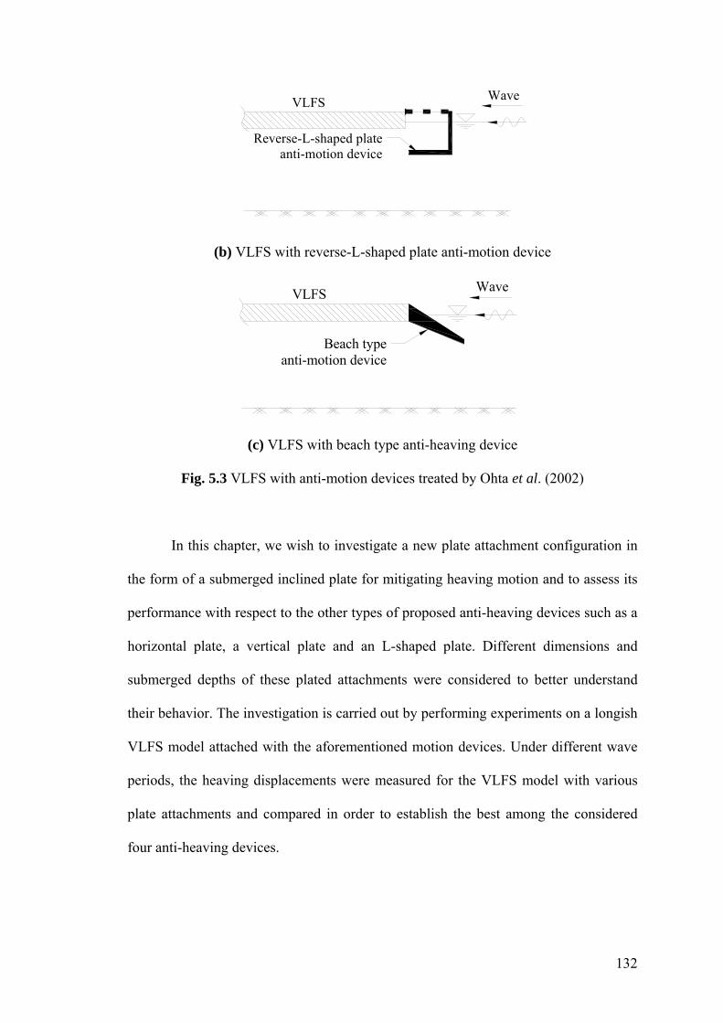
132
WaveVLFS
Reverse-L-shaped plate anti-motion device
(b) VLFS with reverse-L-shaped plate anti-motion device
WaveVLFS
Beach typeanti-motion device
(c) VLFS with beach type anti-heaving device
Fig. 5.3 VLFS with anti-motion devices treated by Ohta et al. (2002)
In this chapter, we wish to investigate a new plate attachment configuration in
the form of a submerged inclined plate for mitigating heaving motion and to assess its
performance with respect to the other types of proposed anti-heaving devices such as a
horizontal plate, a vertical plate and an L-shaped plate. Different dimensions and
submerged depths of these plated attachments were considered to better understand
their behavior. The investigation is carried out by performing experiments on a longish
VLFS model attached with the aforementioned motion devices. Under different wave
periods, the heaving displacements were measured for the VLFS model with various
plate attachments and compared in order to establish the best among the considered
four anti-heaving devices.

133
5.2 Experimental facility and instrumentation
5.2.1 Wave tank
The experimental study was carried out in the two dimensional wave tank as shown in
Fig. 5.4 in the Hydraulic Engineering Laboratory of the National University of
Singapore. The experimental setup for the present study is depicted in Fig 5.5. The
wave tank measures 36m in length, 2m width and 1.3m depth. To meet the size of the
testing model, the tank was partitioned to 0.8m width. The tank has a smooth rigid
horizontal concrete base and side walls. Glass panels of about 20mm thickness are
provided on both sides of the tank for about one eighth length of the tank and placed in
the middle of the tank to facilitate photographic and video recordings and observation
during the test. A spending beach provided at the other end with an average slop of 1:6
made of gravel absorbs the wave energy.
Fig. 5.4 Wave tank in Hydraulic Engineering Laboratory, NUS

134
Wave direction
(b) Plan view
(a) Longitudinal section
36m
2m
0.8m
0.5m
Partition wall
Model of VLFS
16.38m0.5m0.5m12.38m4m
Waveprobe
Anti-motiondevice 0.
95 m
Beach
Model of VLFS
Wavemaker
Waveprobe Potentiometers
= 2.44m2b
Fig. 5.5 Experimental setup

135
5.2.2 Wave generating system
The wave generating system consists of a servo controlled piston type wave maker
fixed at one end of the wave tank. This provides a facility to generate both
monochromatic and random waves according to the input signal.
The wave maker paddle motion was controlled by the input signal received
through the servo controller. The motion of the paddle generates a wave of certain
amplitude and frequency corresponding to the input signal. The frequencies of input
signal are the frequencies of the generated waves. However, the amplitudes of the
input signal are not the amplitudes of the generated waves. So the relationship between
the input signal and the actual values of amplitudes of the generated wave has to be
determined a priori. This relationship was carried out without the model in the channel.
At each frequency, different values of input signal amplitude ranging from 50 – 500
ml/PP were sent to the wave maker and the amplitudes of generated waves at the test
section in the wave tank were measured by wave probes to generate the desired wave
heights.
5.2.3 Data acquisition system
The instrumentations for wave generating system are shown in Fig. 5.6. Frequency and
amplitude signals are set in the HP 33120A function generator as shown in Fig. 5.6a
and are then transferred through the servo controller as shown in Fig. 5.6b, to the wave
paddle to generate the waves.

136
(a) HP 33120A function generator
(b) Servo controller
Fig. 5.6 Wave generating system controller
The time histories of water surface elevation were measured using three wave
probes as shown in Fig. 5.5. The wave probes Kenek CH-4, which includes insulated
coating wire as a conductor along its length, were used. By putting the wave probe into
water and running electric current, a kind of condenser between water and conductor is
formed. Its static electrical capacity is proportional to the water depth. Figure 5.7
shows the instrumentations for wave data acquisition. Each Kenek wave probe was
connected to a Kenek controller (on the right hand side of Fig. 5.7) to set the range of
measurement. Then, all the data is transferred to a personal computer through an
amplifier (on the right hand side of Fig. 5.7).

137
Fig. 5.7 Wave data acquisition system
In order to measure the vertical displacements of the VLFS model, 13 linear
motion potentiometers were installed along the center line of the model at a spacing of
0.2m. The deflection of VLFS is collected using deflection data acquisition system as
shown in Fig. 5.8. On the right hand side is the power supply and the other is the
oscilloscope. Each potentiometer was connected to both the power supply and
oscilloscope. We used potentiometer type with measure range of 10cm and set the
power supply at 10V so that the collected data was in cm unit.
Fig. 5.8 Deflection data acquisition system

138
5.2.4 Testing condition
For regular waves, the wave period is varied from 5s to 10s and the wave height from
0.5m to 1.5m, thereby simulating varying sea conditions. By using a scale of 1:50, the
testing values of wave height range from 1cm to 3cm. The testing values of the wave
period range from 0.8s to 1.3s. The values of wave period were obtained by using the
same Froude number of the testing VLFS model and the real VLFS.
5.2.5 VLFS model
Consider a longish VLFS of length 122m, width 25m and height 3m. By using a scale
of 1:50, we fabricated a model for the VLFS of length 2.44m, width 0.5m, and height
0.06m by pasting a 57mm thick polyethylene foam (specific gravity = 0.019) to the
bottom of a 3mm thick aluminum plate (Young’s modulus = 70GPa, specific gravity =
2.3). Figure 5.9 shows the experimental model. At the fore-end of the model, there are
8 ready bolts installed to attach the anti-heaving device. The floating model was
allowed to move freely in the vertical direction but was restrained from moving in the
horizontal plane by a mooring system consisting of 4 angle plates placed at the 4
corners of the plate model. Oil was put on surface of angle plates so that the friction
between the corner of VLFS and angle plate is negligible.

139
Fig. 5.9 Experimental model placed in wave tank
Table 5.1 gives the pertinent information of the model. The draft of the model
was calculated from the specific gravities of the materials used and validated with the
actual draft value measured from the experiment. The flexural rigidity EI was
calculated from a simple test as shown in Fig. 5.10 which simulates a cantilever beam
under its own weight. This simple test was repeated three times with different
cantilever lengths to check the repeatability of the calculated EI. We measured the
deflection at the free end of the cantilever then used this value to calculate the flexural
rigidity EI of the model by using the deflection relation given by Ye (2008)
4
8sq awEI
= (5.1)
where w is the measured deflection at the free end of the cantilever, qs the self weight
of the model, and a is the cantilever length.
VLFS Model
Ready bolts Angle plate
Potentiometer
Holding system
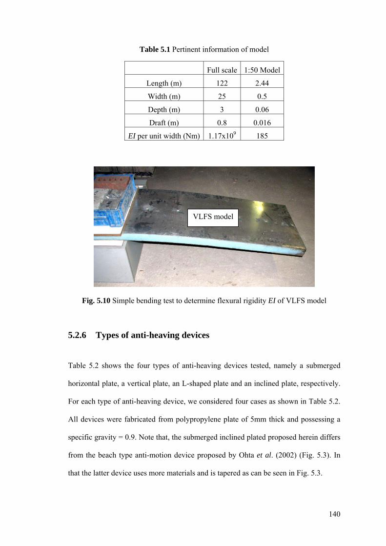
140
Table 5.1 Pertinent information of model
Full scale 1:50 Model
Length (m) 122 2.44
Width (m) 25 0.5
Depth (m) 3 0.06
Draft (m) 0.8 0.016
EI per unit width (Nm) 1.17x10⁹ 185
Fig. 5.10 Simple bending test to determine flexural rigidity EI of VLFS model
5.2.6 Types of anti-heaving devices
Table 5.2 shows the four types of anti-heaving devices tested, namely a submerged
horizontal plate, a vertical plate, an L-shaped plate and an inclined plate, respectively.
For each type of anti-heaving device, we considered four cases as shown in Table 5.2.
All devices were fabricated from polypropylene plate of 5mm thick and possessing a
specific gravity = 0.9. Note that, the submerged inclined plated proposed herein differs
from the beach type anti-motion device proposed by Ohta et al. (2002) (Fig. 5.3). In
that the latter device uses more materials and is tapered as can be seen in Fig. 5.3.
VLFS model

141
The connection of the anti-heaving device to the fore-end of the model was
made possible by using two jigs made of aluminum (2.5cm width and 3mm thickness)
and 8 bolts on top surface of the fore-end (see Fig. 5.9). The anti-heaving device was
bolted to the jigs.
Table 5.2 Anti-heaving devices considered in the experiment
Type of anti-heaving device Case No.
Dimensions and submerged level
Case A1
B = 10cm and dd = 10cm
Case A2
B = 20cm and dd = 10cm
Case A3
B = 10cm and dd = 20cm
(A) Submerged horizontal plate
B (10, 20cm)
WaveAttaching jigsModel
Attachedhorizontal plate
H=9
5cmdd
(10,
20c
m)
Case A4
B = 20cm and dd = 20cm
Case B1
dd = 10cm without slits
Case B2
dd = 10cm with slits of diameter 1cm and spacing 5cm
Case B3
dd = 20cm without slits
(B) Submerged vertical plate
WaveModel
Attachedvertical plate
(with and without slits)
dd (1
0, 2
0cm
)
H=9
5cm
Case B4
dd = 20cm with slits of diameter 1cm and spacing 5cm
Case C1
B = 5cm and dd = 10cm
Case C2
B = 10cm and dd = 10cm
Case C3
B = 5cm and dd = 20cm
(C) Submerged L-shaped plate
Attached L-shaped device
B (5, 10cm)
WaveModel
H=9
5cmdd
(10,
20c
m)
Case C4
B = 10cm and dd = 20cm

142
Case D1
B = 10cm without slits
Case D2
B = 10cm with slits of diameter 1cm and spacing 5cm
Case D3
B = 20cm without slits
(D) Submerged inclined plate (α = 45o)
Attached inclined plateB = 10, 20cm
(with and without slits)
Wave
α
Model
H=9
5cm
Case D4
B = 20cm with slits of diameter 1cm and spacing 5cm
5.3 Experimental procedure
The VLFS model and the various anti-motion devices were fabricated in the Hydraulic
Laboratory. On the top surface of the model, 13 nuts were fixed at an equal spacing of
0.2m. A holding system was prepared near the middle and on top of the wave tank in
order to fix the model and potentiometers. 3 wave probes were positioned in the wave
tank to measure the wave surface elevation.
The model was placed in the wave tank and restrained from horizontal
movement by 4 angle plates each at a corner of VLFS from the holding system. Finally
all 13 potentiometers were connected on top of the model by fixing each tip of the
potentiometer to 1 nut on top of the model and the other end of the potentiometer to
the holding system.
The VLFS model without anti-heaving device was tested first. Then one by one
anti-heaving device was connected to the for-end of the VLFS model and tested. Each
test was repeated three times to check the repeatability of the collected data and to
compute the statistical characteristics of the data. Each model was tested with various
wave period conditions ranging from 0.8s to 1.3s.

143
The time history of water surface elevation was sampled at a rate 100 data pts/s.
The time history of deflection of VLFS at each collected point was sampled at a rate
1600 data pts/s. To measure the time history of the deflection of VLFS under action of
incoming waves without the effect of the reflected waves from the end of the wave
tank, data were collected from the time the waves arrived at the fore-end of the model
up to the time when the reflected waves returned to the aft-end of the model. This time
period includes the steady-state response. The data collected were analyzed and only
the data in the steady-state response were used to study the effectiveness of anti-
heaving devices.
5.4 Experimental results
5.4.1 VLFS with submerged horizontal plate
Figures 5.11 to 5.16 show the vertical response distribution of VLFS without and with
the four cases (A1, A2, A3 and A4) of submerged horizontal plate anti-heaving device
mentioned in Section 5.2.6 for various wave periods ranging from 0.8s to 1.3s,
respectively. The ordinate represents the dimensionless values obtained by dividing the
amplitude w of vertical displacement on the center line of the model by the amplitude
A of the incident wave, while the abscissa represents the position of measuring points
in the longitudinal direction of the model. The wave propagates from right to left.
We can see that all these four anti-heaving devices are effective in reducing the
deflection near the aft-end of the model with more significant for longer anti-heaving
devices A2 and A4 (B = 20cm). According to Ohkusu and Nanba (1996), the motion of
VLFS is proportional to the propagation of waves beneath it. That means all these four
devices are effective in reducing the wave so that the obtained deflection is smaller

144
when compared to that of the basic VLFS. The longer plates have been observed to
provide better reduction effect near the aft-end and this tendency was also presented in
the experimental results by Ohta et al. (1999). However, near the fore-end of the model,
only anti-heaving devices placed at level dd = 10cm (i.e. Cases A1 and A2) are
effective in reducing the deflection while anti-heaving devices placed at level dd =
20cm (i.e. Cases A3 and A4) magnify the deflection instead since these devices placed
at a deeper level have a negative damping effect on the fore-end of the model. Among
these heaving devices, Case A2 seems to be the best device in reducing the deflection
of VLFS.
Fig. 5.11 Nondimensionalized deflection amplitude of VLFS without and with horizontal plate at wave period 0.8s
Incoming wave

145
Fig. 5.12 Nondimensionalized deflection amplitude of VLFS without and with horizontal plate at wave period 0.9s
Fig. 5.13 Nondimensionalized deflection amplitude of VLFS without and with horizontal plate at wave period 1s
Incoming wave
Incoming wave

146
Fig. 5.14 Nondimensionalized deflection amplitude of VLFS without and with horizontal plate at wave period 1.1s
Fig. 5.15 Nondimensionalized deflection amplitude of VLFS without and with horizontal plate at wave period 1.2s
Incoming wave
Incoming wave

147
Fig. 5.16 Nondimensionalized deflection amplitude of VLFS without and with horizontal plate at wave period 1.3s
5.4.2 VLFS with vertical plate
Figures 5.17 to 5.22 show the vertical response distribution of VLFS without and with
four cases (B1, B2, B3 and B4) of vertical plate mentioned in Section 5.2.6 for various
wave periods ranging from 0.8s to 1.3s, respectively. We can see clearly that all these
four devices are effective in reducing the displacement along the model. Apparently,
plates installed at a greater depth dd = 20cm (i.e. Cases B3 and B4) are more effective.
When the wave period is longer, the reductions become less significant since the wave
energy passes through the model under the bottom of the vertical plate. The tendency
of increasing heaving reduction along the model as the installation depth of vertical
plate increases and the waves become shorter was also observed by Ohta et al. (1999).
For a shorter plate dd = 10cm, plate with slits (i.e. Case B2) performs slightly better as
compared to the plate without slits (i.e. Case B1) whereas for the longer plate dd =
Incoming wave

148
20cm, the plate without slits (i.e. Case B3) is better than that with slits (i.e. Case B4).
Among these 4 devices, Case B3 provides the largest reduction in heaving motion.
Fig. 5.17 Nondimensionalized deflection amplitude of VLFS without and with vertical plate at wave period 0.8s
Fig. 5.18 Nondimensionalized deflection amplitude of VLFS without and with vertical plate at wave period 0.9s
Incoming wave
Incoming wave

149
Fig. 5.19 Nondimensionalized deflection amplitude of VLFS without and with vertical plate at wave period 1s
Fig. 5.20 Nondimensionalized deflection amplitude of VLFS without and with vertical plate at wave period 1.1s
Incoming wave
Incoming wave

150
Fig. 5.21 Nondimensionalized deflection amplitude of VLFS without and with vertical plate at wave period 1.2s
Fig. 5.22 Nondimensionalized deflection amplitude of VLFS without and with vertical plate at wave period 1.3s
Incoming wave
Incoming wave

151
5.4.3 VLFS with L-shaped plate
Figures 5.23 to 5.28 show the vertical response distribution of VLFS without and with
four cases (C1, C2, C3 and C4) of L-shaped plate for various wave periods from 0.8s
to 1.3s, respectively. The maximum deflection of VLFS always occurs near the ends of
VLFS. We can see that all these four devices are effective in reducing the displacement
along the model. Apparently, the smallest L-shaped plate (i.e. Case C1) is the least
effective. For a shorter wave (i.e. wave period < 1.1s), Case C2 is the most effective in
reducing the deflection near the fore-end whereas Case C3 is the most effective in
reducing the deflection near the aft-end. As the wave period becomes longer (i.e. wave
period ≥ 1.1s), the effectiveness of the largest L-shaped device (i.e Case C4) becomes
dominant along the model. Ohta et al. (2002) pointed out that L-shape device is
effective in reducing the heaving motion of VLFS especially under action of long
waves. We can see that our results also follow this tendency especially for Case C4
(with the largest L-shaped plate).

152
Fig. 5.23 Nondimensionalized deflection amplitude of VLFS without and
with L-shaped plate at wave period 0.8s
Fig. 5.24 Nondimensionalized deflection amplitude of VLFS without and with L-shaped plate at wave period 0.9s
Incoming wave
Incoming wave

153
Fig. 5.25 Nondimensionalized deflection amplitude of VLFS without and with L-shaped plate at wave period 1s
Fig. 5.26 Nondimensionalized deflection amplitude of VLFS without and with L-shaped plate at wave period 1.1s
Incoming wave
Incoming wave
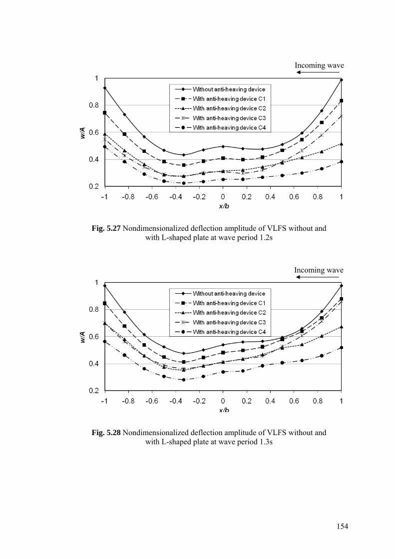
154
Fig. 5.27 Nondimensionalized deflection amplitude of VLFS without and with L-shaped plate at wave period 1.2s
Fig. 5.28 Nondimensionalized deflection amplitude of VLFS without and with L-shaped plate at wave period 1.3s
Incoming wave
Incoming wave

155
5.4.4 VLFS with inclined plate
Figures 5.29 to 5.34 show the vertical response distribution of VLFS without and with
four cases (D1, D2, D3 and D4) of inclined plate mentioned in Section 5.2.6 for
various wave periods from 0.8s to 1.3s, respectively. We can see that all these 4
devices are effective in reducing the displacement along the model. The maximum
deflection of VLFS with shorter inclined plates (i.e. Cases D1 and D2) occurs at fore-
end or aft-end of the model while that of VLFS with longer inclined plates (i.e. Cases
D3 and D4) occurs only at the aft-end of the model since the longer inclined plates
provide more damping effect on the fore-end of the model. The damping effect of the
slits can be seen clearly in the longer plate at the fore-end. As the wave period
becomes longer (i.e. wave period ≥ 1.1s), the effectiveness of the longer plates
becomes dominant along the model. For shorter wave (i.e. wave period <1.1s), the
effectiveness of shorter plates becomes dominant especially at the aft-end of the model.
Fig. 5.29 Nondimensionalized deflection amplitude of VLFS without and with inclined plate at wave period 0.8s
Incoming wave

156
Fig. 5.30 Nondimensionalized deflection amplitude of VLFS without and with inclined plate at wave period 0.9s
Fig. 5.31 Nondimensionalized deflection amplitude of VLFS without and with inclined plate at wave period 1s
Incoming wave
Incoming wave

157
Fig. 5.32 Nondimensionalized deflection amplitude of VLFS without and with inclined plate at wave period 1.1s
Fig. 5.33 Nondimensionalized deflection amplitude of VLFS without and with inclined plate at wave period 1.2s
Incoming wave
Incoming wave

158
Fig. 5.34 Nondimensionalized deflection amplitude of VLFS without and with inclined plate at wave period 1.3s
5.5 Most effective anti-heaving device
In order to find the most effective anti-heaving device, we will compare the
performances of the 4 types of aforementioned anti-heaving device using the same
amount of materials. For the same length of 20cm, we consider the submerged
horizontal plate (Case A2), submerged vertical plate (Case B3), submerged L-shaped
plate (Case C2), and submerged inclined plate (Case D4). Figures 5.35 to 5.40 show
the vertical response distribution of VLFS without and with an anti-heaving device for
various wave periods from 0.8s to 1.3s, respectively. As the wave period becomes
longer (i.e. wave period ≥ 1.2s), the effectiveness of the inclined plate become
dominant along the model. For a shorter wave, the inclined plate is the most effective
device in reducing the deflection near the fore-end while the vertical plate is the most
effective device in reducing the deflection near the aft-end. Therefore, in general, the
Incoming wave

159
inclined plate may be regarded as the most effective device among the four considered
designs for this VLFS model.
Fig. 5.35 Nondimensionalized deflection amplitude of VLFS without and with anti-heaving device of 20cm length at wave period 0.8s
Fig. 5.36 Nondimensionalized deflection amplitude of VLFS without and with anti-heaving device of 20cm length at wave period 0.9s
Incoming wave
Incoming wave

160
Fig. 5.37 Nondimensionalized deflection amplitude of VLFS without and with anti-heaving device of 20cm length at wave period 1s
Fig. 5.38 Nondimensionalized deflection amplitude of VLFS without and with anti-heaving device of 20cm length at wave period 1.1s
Incoming wave
Incoming wave

161
Fig. 5.39 Nondimensionalized deflection amplitude of VLFS without and with anti-heaving device of 20cm length at wave period 1.2s
Fig. 5.40 Nondimensionalized deflection amplitude of VLFS without and with anti-heaving device of 20cm length at wave period 1.3s
For the same length of 10cm, we consider submerged horizontal plate (Case A1),
submerged vertical plate (Case B2) and submerged inclined plate (Case D1). We also
Incoming wave
Incoming wave

162
make comparison with a submerged L-shaped plate (Case C1). Figures 5.41 to 5.46
show the vertical response distribution of VLFS without and with an anti-heaving
device for various wave periods from 0.8s to 1.3s, respectively. We can see clearly that
inclined plate is the most effective device in reducing the deflection along the VLFS.
Even when compared with an attached L-shaped device that uses more materials, the
inclined plate is still more effective. Therefore, we may deduce that the inclined plate
is the most effective anti-heaving device for such a longish floating structure.
Fig. 5.41 Nondimensionalized deflection amplitude of VLFS without and with anti-heaving device of 10cm length at wave period 0.8s
Incoming wave

163
Fig. 5.42 Nondimensionalized deflection amplitude of VLFS without and with anti-heaving device of 10cm length at wave period 0.9s
Fig. 5.43 Nondimensionalized deflection amplitude of VLFS without and with anti-heaving device of 10cm length at wave period 1s
Incoming wave
Incoming wave

164
Fig. 5.44 Nondimensionalized deflection amplitude of VLFS without and with anti-heaving device of 10cm length at wave period 1.1s
Fig. 5.45 Nondimensionalized deflection amplitude of VLFS without and with anti-heaving device of 10cm length at wave period 1.2s
Incoming wave
Incoming wave

165
Fig. 5.46 Nondimensionalized deflection amplitude of VLFS without and with anti-heaving device of 10cm length at wave period 1.3s
5.7 Concluding remarks
In this chapter, we have proposed a submerged inclined plate attached to the fore-end
of VLFS to mitigate the heaving motion. The performance of this anti-heaving device
was tested by attaching it to the fore-end of a longish flexible floating structure. In
order to ascertain the effectiveness of the submerged inclined plate, we compare its
performance against three other types of anti-heaving devices (that previous
researchers have considered), namely the submerged horizontal plate, the vertical plate
and the L-shaped plate.
The effectiveness of all these devices in reducing the heaving motion has been
confirmed by the test results. Among these devices, the newly proposed submerged
inclined plate attachment is the most effective. The reductions of the deflection of the
longish floating structure at the fore-end and aft-end when using this device are noted
to be very significant. Therefore, by using this device, it would be possible to eliminate
Incoming wave

166
the need for an expensive breakwater. In this study, we have only used an inclined
plate of 45o. There should exist an optimal angle of inclination that maximizes the
reduction of the heaving motion of the longish floating structure and future studies
should consider developing a simulation model to seek such an optimal design of
submerged inclined plate attachment.

167
CHAPTER 6
CONCLUSIONS AND RECOMMENDATIONS FOR FUTURE WORK
The main objective of this thesis is to minimize the differential deflection and heaving
motion of Very Large Floating Structure (VLFS). This study was prompted by the fact
that for certain applications of VLFS, there is a need to keep the floating platform calm
and flat so that the uneven heavy loads and wave forces do not affect the smooth operation
of certain equipment on VLFS as well as the structural integrity of VLFS. For example, in
the application of VLFS as a floating container terminal, the larger loading at the stacking
yard in the middle portion of the VLFS causes severe differential deflection that violates
the tight tolerances of the quay crane rails gradient and prevents the smooth operation of
the quay cranes. Other applications of VLFS, such as floating dormitories or hotels,
require minimum heaving, sway and pitching motions.
The innovative solution of using gill cells for minimizing the differential
deflection of VLFS under unevenly heavy load was studied in the first part of the thesis
(see Chapters 2 and 3). The second part investigates the innovative solutions of submerged
plates for minimizing the heaving motion of VLFS under wave action (see Chapters 4 and
5). This chapter summarizes the work and pertinent findings and discusses several
directions for future work in these aforementioned areas.

Conclusions and Recommendations for Future Work
168
6.1 Conclusions
The significant findings in this thesis can be summarized as follows:
1. The optimal designs of gill cells with the view to reduce the differential deflection
and bending stresses in circular VLFSs were analyzed analytically. The VLFS was
modeled as a classical thin (Kirchhoff) plate for the bending analysis and the
optimization exercise was performed using classical optimization algorithms based
on Newton’s method. The study considered a number of design parameters such as
loading magnitudes, loading radius, thickness of top and bottom plates and free
board at the edge of VLFS. The results show that optimal gill cells are very
effective in reducing the maximum differential deflection, bending moments and
shear forces. The percentage reductions in the maximum differential deflection,
bending moments and shear force can be up to 45%, 45% and 55%, respectively,
for the example considered. The optimal design of gill cells is most effective when
the loading radius is bound by 0.5R to 0.75R and the loading magnitude is not too
large. When the thicknesses of the top and bottom plates and the freeboard height
of the circular VLFS are increased, the optimal design of gill cells is more
effective in reducing the maximum shear force but is comparatively less effective
in reducing the maximum differential deflection and bending moments.
2. Also investigated herein is the effect of using stepped plate VLFS in reducing the
differential deflection of VLFS under heavy loads in pontoon-type, circular VLFS
under a central uniform partial load. The results show that this solution is also
effective in reducing the differential deflection in VLFS. By comparing with the

Conclusions and Recommendations for Future Work
169
solution of using gill cells, the results indicate that the solution of using gill cells is
more effective than using stepped plate. This may be attributed to the fact that by
using gill cells, the buoyancy forces are eliminated and this allows uneven
buoyancy forces acting at the bottom hull of the VLFS to somewhat
counterbalance the applied uneven loading. These findings are of crucial
importance in enhancing our understanding on the effectiveness of some possible
solutions in reducing the differential deflection in VLFS and suggesting the best
solution to use in the offshore industry.
3. In addition to circular VLFS, the optimal designs of gill cells with the view to
reducing the slope and bending stresses in the annular VLFS were analyzed by
using a hybrid method of classical optimization algorithms based on Newton’s
method and genetic algorithm. The obtained results show that optimal design of
gill cells in annular VLFS can reduce the maximum slope, shear force and bending
moment up to 59%, 12% and 65%, respectively for the example considered. These
reductions are significant and clearly show the effectiveness of gill cells in
reducing the slope and stress-resultants. Together with the analysis of gill cells in
circular VLFS mentioned above, the findings provide useful benchmark solutions
for designing circular and annular VLFS with gill cells.
4. The optimal design of gill cells and its effectiveness in non-circular VLFS were
also studied by developing an appropriate FEM model for VLFS bending analysis
and using genetic algorithms as an optimization tool. The modeling and
optimization technique were illustrated with examples considering square,
rectangular and I-shape VLFSs. The results show that, with optimal gill cells, the
differential deflection is significantly reduced and the VLFS deflection shape is

Conclusions and Recommendations for Future Work
170
significantly flatter over the entire of VLFS domain. However, for VLFSs with
reentrant corners, reinforcement may be necessary at these corners because of
increase in the maximum von Mises stress in these regions. This is due to the fact
that by using gill cells, the curvature of VLFS is changed. With optimal gill cells,
the curvature of VLFS is much flatter that makes the differential deflection reduce
and deflection shape flatter. At the reentrant corners, the curvature changes
abruptly and makes the bending stresses increase. The FEM model and
optimization technique developed herein can be applied to any shape of floating
structure under any loading configuration to minimize the differential deflection.
In the offshore industry, this model can be employed for the preliminary design
stage of arbitrarily shaped VLFS.
5. Also developed herein is an analytical model to investigate the submerged plate
anti-heaving device for minimizing the motion of circular VLFS under wave
action. This is a precise model considering rigorously the configuration of the
submerged horizontal plate within the framework of linear potential theory. The
obtained results show the effectiveness of this anti-heaving device in reducing not
only the heaving motion but also the stress-resultants of circular VLFS. This may
be due to the fact that the submerged plate reduces the wave height so that the
wave under the VLFS has lower amplitude when compared with the VLFS without
the attached plate.
6. To investigate anti-heaving device for longish VLFS (which are used as floating
runways or piers), it is proposed that a submerged inclined plate be attached to the
fore-end of VLFS. We have tested this device as well as three other types of anti-
heaving devices proposed in previous studies by other authors, namely submerged

Conclusions and Recommendations for Future Work
171
horizontal plate, vertical plate and L-shaped plate. The experiments were carried
out with anti-heaving device attached to the fore-end of a longish flexible floating
structure. The effectiveness of these devices in reducing the heaving motion has
been confirmed by the test results. Among these devices, the newly proposed
inclined plate attachment seems to be the most effective one. The reductions of the
deflection of the longish floating structure at the fore-end and aft-end when using
this device are noted to be very significant. Therefore, by using this device, it
would be possible to eliminate the need for an expensive breakwater
6.2 Recommendations for future work
Based on the findings presented above, the study of innovative solutions for minimizing
differential deflection and heaving motion of VLFS can be extended to widen their
applicability. Some recommendations for future work are listed below:
1. In this study, the investigation of the best innovative solutions for minimizing
differential deflection in VLFS was carried on circular VLFS. Future
investigations should consider other shapes of VLFS.
2. With regard to gill cells for minimizing differential deflection in circular and
annular VLFS, analytical bending solutions used were based on the classical thin
plate theory. In future study, analytical solutions for bending analysis for circular
and annular VLFS can be developed based on Mindlin plate theory for better
prediction response of VLFS especially the stress-resultants.
Conclusions and Recommendations for Future Work
172
3. Some interesting shapes of VLFSs were studied using gill cells to minimize the
differential deflection. The current research only considered the loading area to be
confined in the central portion of the VLFSs. Since the present numerical model is
capable of dealing with arbitrarily shaped VLFS and locations of loaded area, this
study can be extended to investigate other shapes and locations of loaded area.
4. Investigation on minimizing differential deflection in VLFS in this study
considered VLFS in a benign sea state condition where the influence of wave is
neglected. If the VLFS is located in a more severe sea state environment, it is
necessary to perform hydroelastic analysis of the VLFS under wave action as well
and determine the optimal design of gill cells allowing for this hydroelastic
component. Future studies are recommended to investigate the dynamic
hydroelastic problem of VLFS with gill cells.
5. In this study, an analytical model was developed to investigate the submerged
plate anti-heaving device for minimizing the motion of circular VLFS under wave
action was developed for the first time. However, this model is based on 2-D
configuration of VLFS and is restricted to only circular VLFS. Future works are
needed to investigate the effectiveness of submerged plate used in other shapes of
VLFSs. For arbitrarily shaped VLFSs, a 3-D configuration model is required.
Therefore, it is necessary to extend the 2-D model to 3-D model to analyze more
accurately the behavior and response of the real structure.
6. By performing experimental tests on 4 types of anti-heaving devices including a
submerged horizontal plate, a submerged vertical plate, a submerged L-shape plate
and a submerged inclined plate attached to the fore-end of a longish flexible
floating structure, it has been found that the inclined plate is the best anti-heaving

Conclusions and Recommendations for Future Work
173
device. We have only considered the case of an inclined plate of 450. Future
studies should investigate the effect of the angle of inclination on the capability of
the anti-heaving device. In particular, it would be useful to carry out an
optimization study to determine whether there exists an optimal angle of
inclination of the inclined plate as an anti-heaving device. It is also proposed that
future studies focus on developing a numerical technique and computer code for
predicting the heaving motion of arbitrary shaped anti-heaving device and
experimental studies carried out to validate the numerical solutions.

174
REFERENCES
Andrianov A.I. and Hermans A.J. (2003). The Influence of Water Depth on the
Hedroelastic Response of a Very Large Floating Platform.” Marine Structures
16(5), 355-71.
Andrianov A.I. and Hermans A.J. (2004). Hydroelasticity of Elastic Circular plate.
Proceedings of the 19th International Workshop on Water Waves and Floating Bodies,
Cortona, Italy, 7-10.
Andrianov A.I. and Hermans A.J. (2005). Hydroelasticity of a Circular Plate on Water of
Finite or Infinite Depth. Journal of Fluids and Structures 20(5), 719-33.
Andrianov A.I. and Hermans A.J. (2006). Hydroelastic Behavior of a Floating Ring-Shaped
Plate. Journal of Engineering Mathematics 54(1), 31-48.
Avalos R. D., Laura P. A. S., and Larrondo H. (1995). Transverse Vibration and
Buckling of Circular Plates of Discontinuously Varying Thickness Subject to an
In-Plane State of Hydrostatic Stress. Ocean Engineering 22, 105-10.
Chen X.J., Juncher Jensen J., Cui W.C. and Fu S.X. (2003). Hydroelasticity of a
Floating Plate in Multidirectional Waves. Ocean Engineering 30(15), 1997-
2017.
Conn A.R., Gould N.I.M. and Toint, Ph.L. (1991). A Globally Convergent Augmented
Lagrangian Pattern Search Algorithm for Optimization with General Constraints
and Simple Bounds. SIAM Journal on Numerical Analysis 28(2), 545–72.
References
175
CSI (2006). SAP2000 Version 11 Basic Analysis Reference Manual, Computers and
Structures, Berkeley, Calif.
Damaren C.J. (2007). Hyrodynamic Shape Optimization of Thin Floating Plates.
Ocean Engineering 34, 2231-9.
Endo H. (2000). The Behavior of a VLFS and an Airplane During Take off/ Landing
Run in Wave Condition. Marine Structures 13(6), 477-91.
Endo H., Yago K. and Chiaki S. (1998). Elastic Response of a Floating Platform
Stimulated by Dynamic Load. Proceedings of the 14th Ocean Engineering
Symposium, The Society of Naval Architects of Japan, 411-6
Evans D.V. and Davies T.V. (1968). Wave-Ice Interaction. Report 1313. Davidson
Lab-New Jersey: Stevens Institute of Technology.
Fox C. and Squire V.A. (1990). Reflection Transmission Characteristics at The Edge
of Shore Fast Sea Ice. Journal of Geophysical Research 95(C7), 11629-39.
Gill P.E., Murray W., Saunders M.A. and Wright M.H. (1984). Procedures for
Optimization Problems with a Mixture of Bounds and General Linear
Constraints. ACM Transactions on Mathematical Software 10:282-98.
Gill P.E., Murray W. and Wright M.H. (1991). Numerical Linear Algebra and
Optimization. Volume 1. Boston: Addison Wesley, 448p.
Goldberg D.E. (1989). Genetic Algorithms in Search, Optimization, and Machine
Learning. Addison-Wesley Longman, Boston, 412p
Hermans A.J. (2003). The Ray Method for the Deflection of a Floating Flexible
Platform in Short Waves. Journal of Fluids and Structures 17(4), 593-602.

References
176
Hamamoto T. (1994). Dynamic Response of Flexible Circular Floating Islands
Subjected to Stochastic Waves. Proceedings of the International Conference on
Hydroelasticity in Marine Technology, Trondheim, Norway, 433-45.
Hamamoto T. and Tanaka Y. (1992). Coupled Free Vibrational Characteristics of
Artificial Floating Islands, Fluid-Structure Interaction Analysis of Floating
Elastic Circular Plate, Part 1. Journal of Structural and Construction
Engineering 438, 165-77 [in Japanese].
Hamamoto T. and Fujita K. (1995). Three-dimensional BEM-FEM Coupled Dynamic
Analysis of Module-linked Large Floating Structures. Proceedings of the 5th
International Offshore and Polar Engineering Conference, The Hague, The
Netherlands, 329-9.
Hamamoto T. and Fujita K. (2002). Wet-Mode Superposition for Evaluating the
Hydroelastic Response of Floating Structures with Arbitrary Shape. Proceedings
of the 12th International Offshore and Polar Engineering Conference,
Kitakyushu, Japan, 290-97.
Hamamoto T., Hayashi T. and Fujita K. (1996). 3D BEM-FEM Coupled Hydroelastic
Analysis of Irregular Shaped Module-linked Large Floating Structures.
Proceedings of the 6th International Offshore and Polar Engineering
Conference, Los Angeles, California, USA, 362-9.
Hamamoto T., Suzuki A. and Fujita K. (1997). Hybrid Dynamic Analysis of Module-
linked Large Floating Structures Using Plate Elements. Proceedings of the 7th
International Offshore and Polar Engineering Conference, Honolulu, Hawaii,
USA, 362-9.

References
177
Han S.P. (1997). A Globally Convergent Method for Nonlinear Programming. Journal
of Optimization Theory and Applications 22(3), 297-309.
Hermans A.J. (2001). A Geometrical-Optics Approach for the Deflection of a Floating
Flexible Platform. Proceedings of the 16th International Workshop on Water
Waves and Floating Bodies, Hiroshima, Japan, 53-6.
Hong D.C. and Hong S.Y. (2007). Hydroelastic Responses and Drift Forces of a Very-
Long Floating Structure Equipped with a Pin-Connected Oscillating-Water-
Column Breakwater System. Ocean Engineering 34, 696-708.
Ikoma T., Masuda K., Maeda H., Chang-Kyu Rheem and Arita M. (2005). Effects of a
Submerged Vertical Plate and a Wave Energy Absorption Air-Chamber to a
Hydroelastic Response Reduction of VLFS. OCEANS, Proceedings of
MTS/IEEE 1, 719-24.
Irie T., Yamada G. and Aomura S. (1980). Natural Frequencies of Mindlin Circular
Plates. Journal of Applied Mechanics 47, 652-5.
JSSC (1994). Building Cities on the Sea, Japanese Society of Steel Construction,
Tokyo, Japan.
Kashiwagi M. (1998). A B-Spline Galerkin Scheme for Calculating Hydroelastic
Response of a Very Large Floating Structure in Waves. Journal of Marine
Science and Technology 3(1), 37-49.
Kashiwagi M. (2000). A Time-Domain Mode-Expansion Method for Calculating
Transient Elastic Response of a Pontoon-Type VLFS. Journal of Marine Science
and Technology 5, 89-100.
Kim J.W. and Ertekin R.C. (1998). An Eigenfunction Expansion Method for
Predicting Hydroelastic Behavior of a Shallow-Draft VLFS. In: Kashiwagi M,

References
178
Koterayama W, Ohkusu M, editors. Hydroelasticity in Marine Technology,
RIAM, Kyushu University, 47-59.
Kirchhoff G. (1850). Uber Das Gleichgewicht und die Bewegung einer elastischen
Scheibe. Journal fur die reine und angewandte Mathematik 40, 51-88.
Korobkin A.A. (2000). Numerical and Asymptotic Study of the Two-Dimensional
Problem on Hydroelastic Behavior of a Floating Plate in Waves. Journal of
Applied Mechanics and Theoretical Physics 41(2), 286-93.
Le Thi Thu Hang, Wang C.M. and Wu T.Y. (2005). Exact Vibration Results for
Stepped Circular Plates with Free Edges. International Journal of Mechanical
Sciences 47, 1224-48.
Maeda H., Washio Y., Osawa H., Chang-Kyu Rheem, Ikoma T., Onishi Y. and Arita
M. (2000). Hydro-Elastic Response Reduction System of a Very Large Floating
Structure with Wave Energy Absorption Devices. OCEANS 2000 MTS/IEEE
Conference and Exhibition 1, 527-31.
Mamidipudi P. and Webster W.C. (1994). The Motion Performance of a Mat-Like
Floating Airport. Proceedings of the International Conference on
Hydroelasticity in Marine Technology, Trondheim, Norway, 363-75.
MATLAB (2007). Getting Started with MATLAB 2007, The Math Works, Natick, MA.
Meylan M.H. (2001). A Variational Equation for the Wave Forcing of Floating Thin
Plates. Applied Ocean Research 23(4), 195-206.
Meylan M.H. (2002). Wave Response of an Ice Floe of Arbitrary Geometry. Journal
of Geophysical Research 102(C1), 5/1-5/11.

References
179
Meylan M. and Squire V.A. (1993). Finite-Floe Wave Reflection and Transmission
Coefficient from a Semi-Infinite Model. Journal of Geophysical Research
98(C7):12537-42.
Meylan M. and Squire V.A. (1994). The Response of Ice Floe to Ocean Waves.
Journal of Geophysical Research 99 (C1): 891-900.
Meylan M.H. and Squire V.A. (1996). Response of a Circular Ice Floe to Ocean Waves.
Journal of Geophysical Research 101(C4), 8869-84.
Miao Q., Du S., Dong S. and Wu Y. (1996). Hydrodynamic Analysis of a Moored Very Large
Floating Structure. In: Watanabe Y., Editor. Proceedings of the International Workshop
on Very Large Floating Structures, Hayama, Kanagawa, Japan, 201-8.
Mindlin R.D. (1951). Influence of Rotatory Inertia and Shear on Flexural Motions of
Isotropic, Elastic Plates. Journal of Applied Mechanics 18, 31-8.
Newman J.N. (1994). Wave effects on deformable bodies. Applied Ocean Research
16, 47-59.
Newman J.N. (1997). Marine Hydrodynamics. The MIT Press, Cambridge, USA,
402p.
Ohkusu M. (1999). Hydroelastic Interaction of a Large Floating Platform with Head
Seas. Proceedings of the 14th International Workshop on Water Waves and
Floating Bodies, Port Huron, USA, 119-22.
Ohkusu M. and Nanba Y. (1996). Analysis of Hydroelastic Behaviour of a Large
Floating Platform of Thin Plate Configuration in Waves. Proceedings of the
International Workshop on Very Large Floating Structures, Hayama, Japan,
143-48.

References
180
Ohkusu M. and Nanba Y. (1998). Hydroelastic Behaviour of a Large Floating Platform
of Elongated Form on Head Waves in Shallow Water. Proceedings of the 2nd
International Conference on Hydroelasticity in Marine Technology, Fukuoka,
Japan, 177-183.
Ohmatsu S. (1998). Numerical Calculation of Hydroelastic Behaviour of VLFS in
Time Domain. Proceedings of the 2nd International Conference on
Hydroelasticity in Marine Technology, Fukuoka, 89-97.
Ohta H., Torii T., Hayashi N., Watanabe E., Utsunomiya T., Sekita .K and Sunahara S.
(1999). Effect of Attachment of a Horizontal/Vertical Plate on the Wave
Response of a VLFS. Proceedings of the International Workshop on Very Large
Floating Structures, 265-74.
Ohta M., Ozaki M., Matsura M., Tanigaki S., Shuku M. and Inoue S. (2002). A Study
on Progress in Antiwave Performance of Mega-Float. Proceedings of the 12th
International Offshore and Polar Engineering Conference, Kitakyushu, Japan,
275-81.
Peter M., Meylan M.H. and Chung H. (2004). Wave Scattering by a Circular Plate in
Water of Finite Depth: a Closed Form Solution. International Journal of
Offshore and Polar Engineering 14(2), 81-5.
Powell M.J.D. (1978). A Fast Algorithm for Nonlinearly Constrained Optimization
Calculations. Lecture Notes in Mathematics 630,144-57.
Reddy J.N. (1999). Theory and Analysis of Elastic Plates. Taylor & Francis,
Philadelphia, 557p.
Selvadurai A.P.S. (1979). Elastic Analysis of Soil-Foundation Interaction. Amsterdam:
Elsevier, 543p.

References
181
Suzuki H., Yasuzawa Y., Fujikubo M., Okada S., Endo H., Hattori Y., Okada H.,
Watanabe Y., Morikawa M., Ozaki M., Minoura M., Manabe H., Iwata S. and
Sugimoto H. (1997). Structural Response and Design of Large Scale Floating
Structure. In: Proceedings of the 16th International Conference on Offshore
Mechanics and Arctic Engineering, 131-7.
Stoker J.J. (1957). Water Waves. Interscience Publishers, New York, 567p.
Sturova I.V. (1998). The Oblique Incidence of Surface Waves onto the Elastic Band.
In: Kashiwagi M, Koterayama W, Ohkusu M, editors. Hydroelasticity in Marine
Technology, RIAM, Kyushu University, 239-45.
Sturova I.V. (2003). Response of Unsteady External Load on the Elastic Circular Plate
Floating on Shallow Water. Proceedings of the 18th International Workshop on
Water Waves and Floating Bodies, Le Croisic, France, 177-80.
Suzuki H., Yoshida K. (1996). Design flow and strategy for safety of very large
floating structures. Proceedings of the International Workshop on Very Large
Floating Structures, VLFS’96, Hayama, Japan, 21-7.
Takagi K. (2003). Analysis of Hydroelastic Behavior of a Very Large Mobile Offshore
Structure in Waves. Proceedings of the 18th International Workshop on Water
Waves and Floating Bodies, Le Crosic, France, 181-84.
Takagi K. and Nagayasu M. (2001). Hydroelastic Behavior of a Mat-Type Very Large
Floating Structures of Arbitrary Geometry. Proceedings of the MTS/IEEE
Conference and Exhibition Ocean, Honolulu, USA, 3, 1923-9.
Takagi K. and Nagayasu M. (2007). Ray Theory for Predicting Hydroelastic Behavior
of a Very Large Floating Structure in Waves. Ocean Engineering 34, 362-70.

References
182
Takagi K. and Noguchi J. (2005). PFFT-NASTRAN Coupling for Hydroelastic
Problem of VLMOS in Waves. Proceedings of the 20th International Workshop
on Water Waves and Floating Bodies, Longyearbyen, Spitsbergen, Norway, 241-
44.
Takagi K., Yamada A., Kohara K. and Ikebuchi T. (1998). Experimental Research on
Slamming of a Very Large Floating Structure. Journal of the Kansai Society of
Naval Architects 230, 283-90 [in Japanese].
Takagi K., Shimada K. and Ikebuchi Y. (2000). An Anti-Motion Device for a Very
Large Floating Structure. Marine Structures 13, 421-36.
Takaki M. and Gu X. (1996a). Motions of a Floating Elastic Plate in Waves. Journal
of the Kansai Society of Naval Architects 180, 331-9.
Takaki M. and Gu X. (1996b). On Motion Performance of a Huge Floating Structure
in Waves. In: Watanabe Y., editor. Proceedings of the International Workshop
on Very Large Floating Structures, Hayama, Kanagawa, Japan, 157-64.
Timoshenko S.P., Woinowsky-Krieger S. (1959). Theory of Plates and Shells. New
York: McGraw-Hill, 580p.
Tsubogo T. (2000). A Study on the Hydroelastic Behaviour of a Pontoon-Type Large
Floating Disk. Journal of the Kansai Society of Naval 188, 295-302 [in
Japanese].
Utsunomiya T., Watanabe E. and Eatock Taylor R. (1998). Wave Response Analysis
of a Box-Like VLFS Close to a Breakwater. Proceedings of the 17th
International Conference on Offshore Mechanics and Arctic Engineering, 1-8.
Utsunomiya T., Watanabe E., Kuramoto M., Sunahara S., Sekita K., Hayashi N., Torii
T. and Ohta H. (2000). Wave Response Analysis of an Elastic Floating Body

References
183
with Submerged Horizontal Plate. Proceedings of the 15th Ocean Engineering
Symposium, The Society of Naval Architects of Japan, 191-98.
Wang C.M. and Wang C.D. (2005). Hydroelastic Analysis of a Super-Large Floating
Container Terminal. Floating Container Terminal Research Report No. 2,
Submitted to MPA and JCPL, Centre for Offshore Research and Engineering,
National University of Singapore, Singapore.
Wang C.M., Xiang Y., Utsunomiya T. and Watanabe E. (2001). Evaluation of Modal
Stress Resultants in Freely Vibrating Plates. International Journal of Solids and
Structures 38(36-37), 6525-58.
Wang C.M., Xiang Y., Watanabe E. and Utsunomiya T. (2004). Mode Shapes and
Stress-Resultants of Circular Mindlin Plates with Free Edges. Journal of Sound
and Vibration 276, 511-25.
Wang C.M., Wu T.Y., Choo Y.S., Ang K.K., Toh A.C., Mao W.Y. and Hee A.M
(2006). Minimizing Differential Deflection in a Pontoon-Type Very Large
Floating Structure via Gill Cells. Marine Structures 19(1), 70-82.
Wang J. (1992). Free Vibration of Stepped Circular Plates on Elastic Foundations.
Journal of Sound and Vibration 159, 175-81.
Watanabe E. (2003). Floating Bridges: Past and Present. Structural Engineering
International 13(2), 128-32.
Watanabe E. and Utsunomiya T. (1996). Transient Response Analysis of a VLFS at
Airplane Landing. In: Watanabe E., Editor. Proceedings of the International
Workshop on Very Large Floating Structures, Hayama, Kanagawa, Japan, 243-7.
References
184
Watanabe E., Utsunomiya T. and Tanigaki S. (1998). A Transient Response Analysis
of a Very Large Floating Structure by Finite Element Method. Structural
Engineering/Earthquake Engineering, JSCE 15(2), 155s-63s.
Watanabe E., Utsunomiya T. and Kuramoto M. (2003a). Wave Response Analysis of
VLFS with an Attached Submerged Plate. International Journal of Offshore and
Polar Engineering 13, 190-7.
Watanabe E., Utsunomiya T., Wang C.M. and Xiang Y. (2003b). Hydroelastic
Analysis of Pontoon-type circular VLFS. Proceedings of the 13th International
Offshore and Polar Engineering Conference, Honolulu, USA 1, 93-9.
Watanabe E., Utsunomiya T. and Wang C.M. (2004a). Hydroelastic Analysis of
Pontoon-Type VLFS: a Literature Survey. Engineering Structures 26(2), 245-56.
Watanabe E., Wang C.M., Utsumomiya T. and Moan T. (2004b). Very Large Floating
Structures: Applications, Analysis and Design. CORE Report 2004-02,
Singapore, 30p.
Watanabe E., Utsunomiya T., Wang C.M. and Le Thi Thu Hang (2006). Benchmark
Hydroelastic Responses of Circular VLFS under Wave Action. Engineering
Structures 28, 423-30.
Wehausen J.V. and Laitone E.V. (1960). Surface Waves. Encyclopedia of Physics,
Springer-Verlage, Berlin 9, 446-814.
Wu C., Watanabe E. and Utsunomiya T. (1995). An eigenfunction expansion-matching
method for analyzing the wave induced responses of an elastic floating plate.
Applied Ocean Research 17, 301-10.
Xiang Y. and Zhang L. (2004). Free Vibration Analysis of Stepped Circular Mindlin
Plates.” Journal of Sound and Vibration 280, 633-55.
References
185
Yako K. and Endo H. (1996). On the Hydroelastic Response of Box-shaped Floating
Structures with Shallow Draft. Journal of the Kansai Society of Naval Architects
180, 341-52.
Ye J.Q. (2008). Structural Analysis and Stress Analysis: Theories, Tutorials and
Examples. London: Taylor & Francis.
Yoneyama H., Hiraishi T. and Ueda S. (2004). Recent Technological Advances of
Ship Mooring Analysis and Construction of Floating Structures in Japan. PIANC
Bulletin 116, 79-89.
Zhao C., Zhang J. and Huang W. (2007). Vibration Reduction of Floating Elastic
Plates in Wave Waters. Marine Structures 20, 71-99.
Zilman G. and Miloh T. (2000). Hydroelastic Buoyant Circular Plate in Shallow
Water: a Closed Form Solution. Applied Ocean Research 22, 191-8.

186
LIST OF PUBLICATIONS
INTERNATIONAL JOURNAL
Wang C.M., Pham D.C. and Ang K.K. (2006). Effectiveness and Optimal Design of
Gill Cells in Minimizing Differential Deflection in Circular VLFS. Engineering
Structures 29(8), 1845-53.
D.C. Pham, C.M. Wang and T. Utsunomiya (2008). Hydroelastic Analysis of a
Pontoon-Type Circular VLFS with an Attached Submerged Plate. Applied Ocean
Research 30(4), 287-96.
Pham D.C. and Wang C.M. (2009). Optimal Layout of Gill Cells for Very Large
Floating Structures. Journal of Structural Engineering. (In Press)
Pham D.C., Wang C.M. and Emma P.B. (2009). Experimental Study on Anti-Heaving
Devices for a Longish VLFS. The Journal of the Institution of Engineers,
Singapore, 02(4).
INTERNATIONAL CONFERENCE
Pham D.C., Wang C.M. and Ang K.K. (2005). Minimizing Differential Deflection and
Stresses in VLFS Using Gill Cells. Proceedings of the Eighteenth KKCNN
Symposium on Civil Engineering, Kaohsiung, Taiwan, 829-34.

List of Publications
187
Pham D.C., Wang C.M. and Ang K.K. (2007). Optimal Design of Gill Cells for Very
Large Floating Structures. The 7th International Conference on Optimization:
Technique and Application (ICOTA7), Kobe, Japan, 255-36.
Pham D.C. and Wang C.M. (2007). Effectiveness and Optimal Design of Gill Cells in
Minimizing Slope in annular VLFS. Proceedings of the Twentieth KKCNN
Symposium on Civil Engineering, Jeju, Korea, 255-8.
Pham D.C., Wang C.M. and Emma P.B. (2008). Anti-Heaving Devices for VLFS.
Proceedings of the Twenty First KKCNN Symposium on Civil Engineering,
Singapore, 286-89.