Innovative One-pass Lining Solution for Doha’s Deep Tunnel ... 2017... · Proceedings of the...
10
Proceedings of the World Tunnel Congress 2017 – Surface challenges – Underground solutions. Bergen, Norway. 1 1 INTRODUCTION All sewer tunnels require both a primary structure tunnel system to withstand the ground and groundwater forces, and an inner lining to protect the durability of the primary system from the effects of corrosive sewer gasses. The more common design and construction method is a two-pass lining consisting of two parts: a structural precast lining, made up of precast concrete segments, and a thick sacrificial concrete layer with a High-density polyethylene (HDPE) or a Polyvinyl chloride (PVC) membrane cast inside the tunnel using specialised travelling formwork. This more “conservative” approach provides a thick double layer of corrosion protection from aggressive sewer gases, thereby lowering the tunnel’s maintenance needs and extending its life cycle. In the one-pass lining, the HDPE membrane and a thinner sacrificial concrete layer are cast together with the structural part of the segment in a factory. Once installed in the tunnel, the only remaining activity is to weld the joints. While the one-pass has been applied on projects for at least two decades, it is not used as often as the two-pass because is still considered somewhat “untried” and there is a fear of hidden built-in construction defects. However, it offers significant benefits to schedule, cost, quality and safety during construction if properly executed. This paper presents the implementation process and main challenges during the design and development of the one-pass lining on the Inner Doha Re-sewerage Implementation Strategy (IDRIS) programme. 2 IDRIS PROGRAMME The IDRIS programme is being developed by the Public Works Authority (Ashghal) with CH2M as the Programme Management Consultant (PMC). The project comprises the construction of a 16-kilometre-deep tunnel main trunk sewer (MTS), divided into three branches (Eastern, Northern and Western) and seven lateral interceptor sewers with a total length of about 24 kilometres. Sewage flows from central and south Doha are planned to be conveyed through a new pump station to the existing Doha South Sewage Treatment Works. Innovative One-pass Lining Solution for Doha’s Deep Tunnel Sewer System A. M. Najder Olliver CH2M, Doha, Qatar. T. Lockhart Bouygues Travaux Publics, Doha, Qatar. ABSTRACT: Large diameter sewer tunnels can be built with either a two-pass or one-pass lining to protect the structural concrete from aggressive sewer gases, thereby lowering a tunnel’s maintenance needs and extending its life cycle. The use of a one-pass lining can reduce the construction schedule, save capital costs and improve overall quality. A one-pass lining solution is being applied for the first time in the Middle East on the main trunk sewer of the Inner Doha Re-sewerage Implementation Strategy (IDRIS), a programme developed by the Public Works Authority (Ashghal) in the State of Qatar. CH2M is the Programme Management Consultant, with the tunnel designed and constructed by Bouygues Travaux Publics and Urbacon Trading & Contracting Joint Venture. This paper presents the implementation process and main challenges during the design and development of the lining.
Transcript of Innovative One-pass Lining Solution for Doha’s Deep Tunnel ... 2017... · Proceedings of the...

Proceedings of the World Tunnel Congress 2017 – Surface challenges – Underground solutions. Bergen, Norway.
1
1 INTRODUCTION
All sewer tunnels require both a primary structure tunnel system to withstand the ground and groundwater forces, and an inner lining to protect the durability of the primary system from the effects of corrosive sewer gasses.
The more common design and construction method is a two-pass lining consisting of two parts: a structural precast lining, made up of precast concrete segments, and a thick sacrificial concrete layer with a High-density polyethylene (HDPE) or a Polyvinyl chloride (PVC) membrane cast inside the tunnel using specialised travelling formwork. This more “conservative” approach provides a thick double layer of corrosion protection from aggressive sewer gases, thereby lowering the tunnel’s maintenance needs and extending its life cycle.
In the one-pass lining, the HDPE membrane and a thinner sacrificial concrete layer are cast together with the structural part of the segment in a factory. Once installed in the tunnel, the only remaining activity is to weld the joints.
While the one-pass has been applied on projects for at least two decades, it is not used as often as the two-pass because is still considered
somewhat “untried” and there is a fear of hidden built-in construction defects. However, it offers significant benefits to schedule, cost, quality and safety during construction if properly executed.
This paper presents the implementation process and main challenges during the design and development of the one-pass lining on the Inner Doha Re-sewerage Implementation Strategy (IDRIS) programme.
2 IDRIS PROGRAMME
The IDRIS programme is being developed by the Public Works Authority (Ashghal) with CH2M as the Programme Management Consultant (PMC). The project comprises the construction of a 16-kilometre-deep tunnel main trunk sewer (MTS), divided into three branches (Eastern, Northern and Western) and seven lateral interceptor sewers with a total length of about 24 kilometres. Sewage flows from central and south Doha are planned to be conveyed through a new pump station to the existing Doha South Sewage Treatment Works.
Innovative One-pass Lining Solution for Doha’s Deep Tunnel Sewer System
A. M. Najder Olliver CH2M, Doha, Qatar.
T. Lockhart Bouygues Travaux Publics, Doha, Qatar.
ABSTRACT: Large diameter sewer tunnels can be built with either a two-pass or one-pass lining to protect the structural concrete from aggressive sewer gases, thereby lowering a tunnel’s maintenance needs and extending its life cycle. The use of a one-pass lining can reduce the construction schedule, save capital costs and improve overall quality. A one-pass lining solution is being applied for the first time in the Middle East on the main trunk sewer of the Inner Doha Re-sewerage Implementation Strategy (IDRIS), a programme developed by the Public Works Authority (Ashghal) in the State of Qatar. CH2M is the Programme Management Consultant, with the tunnel designed and constructed by Bouygues Travaux Publics and Urbacon Trading & Contracting Joint Venture. This paper presents the implementation process and main challenges during the design and development of the lining.
Proceedings of the World Tunnel Congress 2017 – Surface challenges – Underground solutions. Bergen, Norway.
2
The gravity based system will link several catchments and enable the decommissioning of more than twenty aged pump stations currently located in residential and commercial areas. Therefore, environmental impacts such as odour nuisance and sewage overflows on the existing network will be minimised, while accommodating the expected population growth for years to come.
Bouygues Travaux Publics and Urbacon Trading & Contracting Joint Venture (BUJV), under a Design-Build contract, will construct the three MTS branches using two earth pressure balance (EPB) tunnel boring machines (TBMs) from Herrenknecht. Eleven shafts ranging between 22 and 42 metres deep, and supported by diaphragm walls, sprayed concrete lining or concrete segments installed by a Vertical Shaft Machine (VSM), will serve as work shafts and future access shafts.
The Project is the first in the region to implement CEEQUAL, the international evidence-based sustainability assessment, rating and awards scheme for civil engineering, infrastructure, landscaping and works in public spaces.
The project is planned to be completed in 2019.
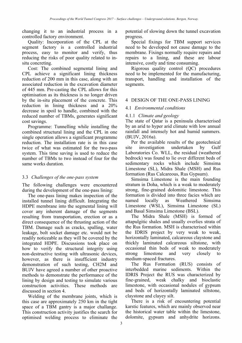
3 ONE-PASS VS TWO-PASS LINING 3.1 Background The original concept and tender design of the three-metre inner diameter tunnel lining system proposed for the project was developed by CH2M (CH2M, 2013). This was based on the two-pass lining solution previously implemented on Singapore’s Deep Tunnel Sewerage System (DTSS) and the Strategic Tunnel Enhancement Programme (STEP) in Abu Dhabi, UAE. To achieve the required maintenance free design life of 100 years, this system included ground support in the form of a precast concrete segmental lining with a separate corrosion protection lining (CPL) comprising of a 250-mm thick sacrificial cast-in-place concrete layer integral with a HDPE membrane (Figure 1).
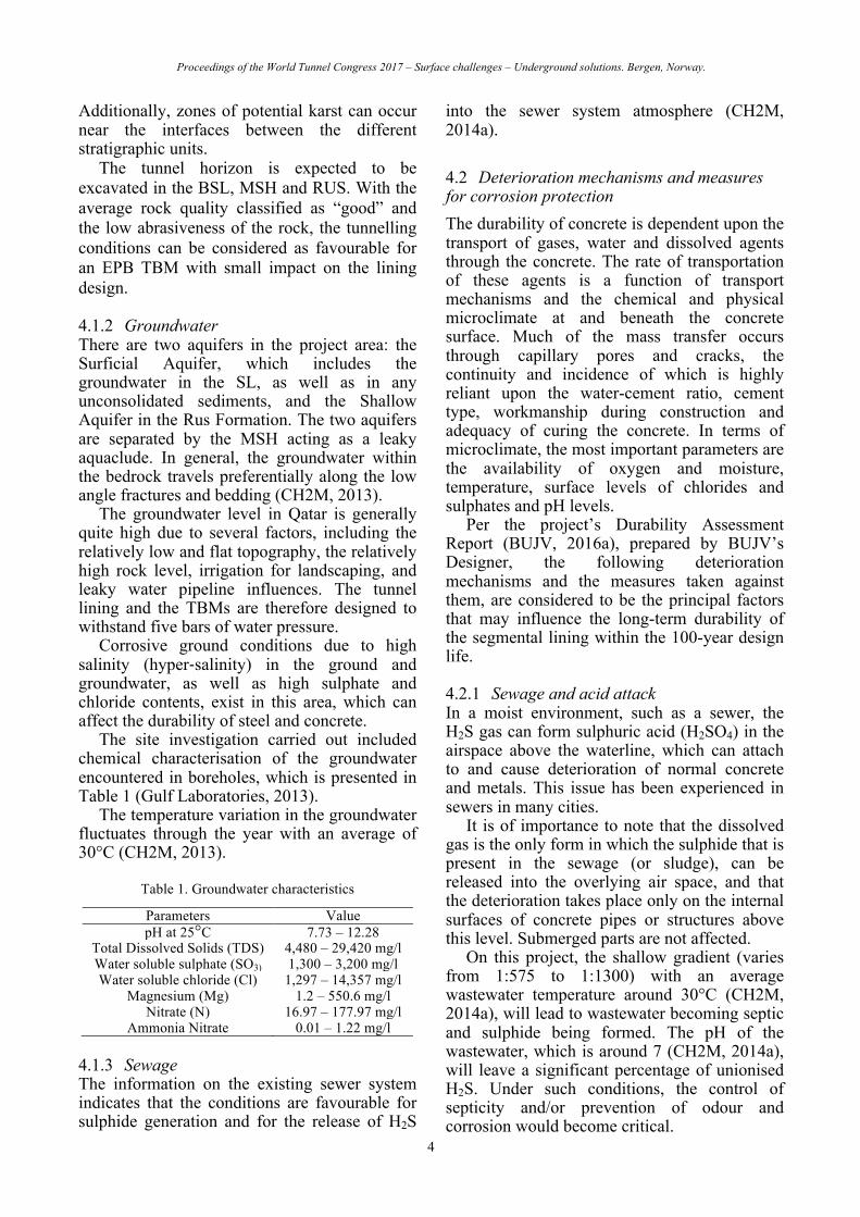
BUJV proposed an acceptable alternative incorporating the key feature of the CPL cast into the structural segmental lining system (Figure 2), thus allowing construction to be a one-pass approach and therefore reducing the required number of TBMs from four to two
while still achieving the prescribed completion date.
CH2M studied both systems in detail and performed a comparative analysis identifying the benefits and drawbacks associated with the alternative proposal as compared to the more conservative reference design.
Figure 1. Typical tunnel cross section as per the reference
design
Figure 2. Typical tunnel cross section as per the BUJV’s
proposal
3.2 Benefits of the one-pass system The benefits associated with BUJV’s one-pass lining were as follows:
Safety: Construction of the cast-in-place secondary lining is a labour-intensive operation carried out in a harsh environment. The one-pass alternative will significantly improve the safety and working conditions of the workers by eliminating this entire cast in place operation,
Proceedings of the World Tunnel Congress 2017 – Surface challenges – Underground solutions. Bergen, Norway.
3
changing it to an industrial process in a controlled factory environment.
Quality: Incorporation of the CPL at the segment factory is a controlled industrial process, easy to monitor and verify, thus reducing the risks of poor quality related to in-situ concreting.
Cost: The combined segmental lining and CPL achieve a significant lining thickness reduction of 200 mm in this case, along with an associated reduction in the excavation diameter of 445 mm. Pre-casting the CPL allows for this optimisation as its thickness is no longer driven by the in-situ placement of the concrete. This reduction in lining thickness and a 20% decrease in spoil to handle, combined with the reduced number of TBMs, generates significant cost savings.
Programme: Tunnelling while installing the combined structural lining and the CPL in one single operation allows a significant programme reduction. The installation rate is in this case twice of what was estimated for the two-pass system. This time saving is used to reduce the number of TBMs to two instead of four for the same works duration.
3.3 Challenges of the one-pass system The following challenges were encountered during the development of the one-pass lining:
The one-pass lining makes inspection of the installed tunnel lining difficult. Integrating the HDPE membrane into the segmental lining will cover any inherent damage of the segments resulting from transportation, erection or as a direct consequence of the thrusting action of the TBM. Damage such as cracks, spalling, water leakage, bolt socket damage etc. would not be readily noticeable as they will be covered by the integrated HDPE. Discussions took place on how to verify the structural integrity using non-destructive testing with ultrasonic devices, however, as there is insufficient industry demonstration of such testing, CH2M and BUJV have agreed a number of other proactive methods to demonstrate the performance of the lining by design and testing to simulate various construction activities. These methods are discussed in section 4.
Welding of the membrane joints, which is this case are approximately 250 km in the tight space of a TBM gantry is a major challange. This construction activity justifies the search for optimised welding process to eliminate the
potential of slowing down the tunnel excavation progress.
Special fixings for TBM support services need to be developed not cause damage to the membrane. Fixings normally require repairs and repairs to a lining, and these are labour intensive, costly and time consuming.
Rigorous quality control (QC) procedures need to be implemented for the manufacturing, transport, handling and installation of the segments.
4 DESIGN OF THE ONE-PASS LINING 4.1 Environmental conditions 4.1.1 Climate and geology The state of Qatar is a peninsula characterised by an arid to hyper arid climate with low annual rainfall and intensely hot and humid summers. (BUJV, 2016a).
Per the available results of the geotechnical site investigation undertaken by Gulf Laboratories Co. WLL, the residual (weathered bedrock) was found to lie over different beds of sedimentary rocks which include Simsima Limestone (SL), Midra Shale (MSH) and Rus formation (Rus Calcareous, Rus Gypsum).
Simsima Limestone is the main founding stratum in Doha, which is a weak to moderately strong, fine-grained dolomitic limestone. This formation is divided into three facies which are named locally as Weathered Simsima Limestone (WSL), Simsima Limestone (SL) and Basal Simsima Limestone (BSL).
The Midra Shale (MSH) is formed of attapulgitic shales and usually overlies strata of the Rus formation. MSH is characterised within the IDRIS project by very weak to weak, horizontally laminated, calcareous claystone and thickly laminated calcareous siltstone, with occasional thin beds of weak to moderately strong limestone and very closely to medium-spaced fractures.
The Rus Formation (RUS) consists of interbedded marine sediments. Within the IDRIS Project the RUS was characterized by fine-grained, weak chalky and bioclastic limestone, with occasional nodules of gypsum and beds of horizontally laminated siltstone, claystone and clayey silt.
There is a risk of encountering potential karstic features, which are mainly observed near the historical water table within the limestone, dolomite, gypsum and anhydrite horizons.
Proceedings of the World Tunnel Congress 2017 – Surface challenges – Underground solutions. Bergen, Norway.
4
Additionally, zones of potential karst can occur near the interfaces between the different stratigraphic units.
The tunnel horizon is expected to be excavated in the BSL, MSH and RUS. With the average rock quality classified as “good” and the low abrasiveness of the rock, the tunnelling conditions can be considered as favourable for an EPB TBM with small impact on the lining design.
4.1.2 Groundwater There are two aquifers in the project area: the Surficial Aquifer, which includes the groundwater in the SL, as well as in any unconsolidated sediments, and the Shallow Aquifer in the Rus Formation. The two aquifers are separated by the MSH acting as a leaky aquaclude. In general, the groundwater within the bedrock travels preferentially along the low angle fractures and bedding (CH2M, 2013).
The groundwater level in Qatar is generally quite high due to several factors, including the relatively low and flat topography, the relatively high rock level, irrigation for landscaping, and leaky water pipeline influences. The tunnel lining and the TBMs are therefore designed to withstand five bars of water pressure.
Corrosive ground conditions due to high salinity (hyper-salinity) in the ground and groundwater, as well as high sulphate and chloride contents, exist in this area, which can affect the durability of steel and concrete.
The site investigation carried out included chemical characterisation of the groundwater encountered in boreholes, which is presented in Table 1 (Gulf Laboratories, 2013).
The temperature variation in the groundwater fluctuates through the year with an average of 30°C (CH2M, 2013).
Table 1. Groundwater characteristics
Parameters Value pH at 25°C 7.73 – 12.28
Total Dissolved Solids (TDS) 4,480 – 29,420 mg/l Water soluble sulphate (SO3) 1,300 – 3,200 mg/l Water soluble chloride (Cl) 1,297 – 14,357 mg/l
Magnesium (Mg) 1.2 – 550.6 mg/l Nitrate (N) 16.97 – 177.97 mg/l
Ammonia Nitrate 0.01 – 1.22 mg/l
4.1.3 Sewage The information on the existing sewer system indicates that the conditions are favourable for sulphide generation and for the release of H2S
into the sewer system atmosphere (CH2M, 2014a).
4.2 Deterioration mechanisms and measures for corrosion protection The durability of concrete is dependent upon the transport of gases, water and dissolved agents through the concrete. The rate of transportation of these agents is a function of transport mechanisms and the chemical and physical microclimate at and beneath the concrete surface. Much of the mass transfer occurs through capillary pores and cracks, the continuity and incidence of which is highly reliant upon the water-cement ratio, cement type, workmanship during construction and adequacy of curing the concrete. In terms of microclimate, the most important parameters are the availability of oxygen and moisture, temperature, surface levels of chlorides and sulphates and pH levels.
Per the project’s Durability Assessment Report (BUJV, 2016a), prepared by BUJV’s Designer, the following deterioration mechanisms and the measures taken against them, are considered to be the principal factors that may influence the long-term durability of the segmental lining within the 100-year design life.
4.2.1 Sewage and acid attack In a moist environment, such as a sewer, the H2S gas can form sulphuric acid (H2SO4) in the airspace above the waterline, which can attach to and cause deterioration of normal concrete and metals. This issue has been experienced in sewers in many cities.
It is of importance to note that the dissolved gas is the only form in which the sulphide that is present in the sewage (or sludge), can be released into the overlying air space, and that the deterioration takes place only on the internal surfaces of concrete pipes or structures above this level. Submerged parts are not affected.
On this project, the shallow gradient (varies from 1:575 to 1:1300) with an average wastewater temperature around 30°C (CH2M, 2014a), will lead to wastewater becoming septic and sulphide being formed. The pH of the wastewater, which is around 7 (CH2M, 2014a), will leave a significant percentage of unionised H2S. Under such conditions, the control of septicity and/or prevention of odour and corrosion would become critical.

Proceedings of the World Tunnel Congress 2017 – Surface challenges – Underground solutions. Bergen, Norway.
5
Septicity modelling based on the tunnel flows and corresponding depths and velocities at selected shafts has been performed for the start-up and built-out conditions, based on the hydraulic modelling information carried out in InfoWorks provided by CH2M. It was deemed likely that the peak drop flows would lead to turbulence in shafts and hence higher risk of hydrogen sulphide and sulphuric acid formation. To establish the potential corrosion rates for concrete during the design life period, it is necessary to consider the rate of build-up of average annual flow and the impact this has on the mechanism for corrosion due to sulfuric acid.
Calculations in line with those presented by Loganathan et al (2008) and Pomeroy et al (1974) were produced, based on a linear increase in average annual flow rates. The “Pomeroy” factor for tunnels is generally taken as 1.5 to allow for localised loss of concrete, whereas the factor would be in the range of 1.5 to 10 in shafts and non-TBM tunnel adits. The service life assessments took into consideration the outputs from the hydraulic physical and Computational Fluid Dynamics (CFD) modelling.
The use of calcareous aggregate (limestone or dolomite) is chosen because it increases the alkalinity of concrete and thus prolongs the life of structures subject to damage by sulphide conditions (Stutterheim and Van Aardt, 1953).
The corrosion rate of a cement bonded pipe is estimated by finding the rate at which H2S will reach the pipe wall and the amount reaching the wall that will be oxidised and available for reaction. Therefore, the average release of H2S flux to the sewer wall per Pomeroy et al (1974) was calculated.
Per the design, the average rate of corrosion of concrete was estimated to be 0.825 mm/year. A partial “Pomeroy” factor of 1.5 for the TBM tunnels was applied to obtain the maximum localised corrosion rate, which was estimated at 1.238 mm/year. It is therefore concluded, that over a period of 100 years, based on the very conservative assumption that if parts of the HDPE membrane (which can provide the required durability by itself) have been impaired in the tunnel’s early days, between 82 mm and 120 mm of sacrificial concrete could have eroded in localised areas. A sacrificial concrete thickness of 120 mm in the TBM tunnels, is therefore considered to provide adequate
reassurance regarding structural integrity for the 100-year design life.
4.2.2 Chloride induced corrosion Due to the high salinity of the groundwater, the use of steel fibre reinforced concrete (SFRC) is advantageous. In conventionally reinforced concrete, adequate protection to the reinforcing steel is provided by a combination of concrete quality and cover to prevent chloride induced corrosion. However, in SFRC, there is virtually no cover to the fibres close to the surface and the design rules for durability, which apply to conventionally reinforced concrete, are no longer directly relevant.
For SFRC, which has been used widely over the last 30 years, it has been reported by researchers that corrosion is less active as compared to steel bar reinforcement (BUJV, 2016a). A fibre, being discontinuous, is not capable of giving rise to galvanic corrosion. Even if fibres do corrode, the small volume of the fibre is insufficient to create the bursting stresses associated with the corrosion of larger diameter reinforcement bars. For well compacted concrete, the corrosion of fibres is restricted to the surface of the concrete.
The use of SFRC was also considered due to the proven increase in ductility (strain-softening behaviour when tested in bending) in relation to unreinforced concrete and effective elimination of spalling damage, as well as the ability of controlling drying shrinkage cracking.
SFRC was therefore chosen for the segmental lining.
4.2.3 Sulphate attack Conventional sulphate attack is usually confined to concrete below ground and may occur when sulphates in the ground or groundwater react with hydrates in the cement. The products of the reaction are expansive compounds (gypsum and ettringite) that can lead to cracking and spalling of the concrete.
Whilst cracking due to sulphate attack is limited (compared with reinforcement corrosion), it is still a significant deterioration mechanism causing softening of the cement matrix and concrete section loss. The main factors affecting the rate of sulphate attack are concentration and type of sulphate, pH value and temperature of the soil or groundwater, cement type (and content) used, water-cement ratio applied and the compaction and curing of the concrete.
Proceedings of the World Tunnel Congress 2017 – Surface challenges – Underground solutions. Bergen, Norway.
6
The sulphate-bearing groundwater in Doha is considered to have a long-term effect on concrete deterioration. This mechanism of attack can typically be mitigated using high-quality concretes containing cement replacement materials, and supplementary protection such as membranes or sacrificial concrete layers.
4.3 Concrete mix design The developed concrete mix design in Table 2 was based on experience from other local tunnelling projects such as the Abu Hamour Stormwater Outfall and Doha Metro (BUJV, 2016a).
Table 2. Concrete Mix Design
Property Value Binder combination [% by weight of
total binder content] 30% OPC + 65% GGBS + 5% MS*
Aggregate type Limestone Max w/c ration [-] 0.38
Min binder content [kg/m3] 378 Classification for structural design 4C Min concrete grade (cylinder/cube)
[MPa] 50/60
* OPC = Ordinary Portland Cement GGBS = Ground Granulated Blast furnace Slag MS = Micro Silica (silica fume) The production testing includes field and
laboratory testing of fresh concrete (slump, temperature, air content and fibre washout), laboratory testing of hard concrete (compressive strength, water permeability, water absorption, acid soluble chloride content, flexural strength and fibre distribution) as well as sampling and testing of raw constituent materials. Sulphate resistance testing was also conducted during the preconstruction phase by applying the SVA method in accordance with Deutsches Institut für Bautechnik (DIBt), the German building authority.
4.4 Structural design The tunnel lining was designed according to Eurocode, fib Model Code 2010 and used the Convergence-Confinement approach per Panet (2001), with explicit simulations of the construction stages (BUJV, 2016b). BUJV’s experience validated on past projects has been used to estimate sensitive parameters such as the
deconfinement ratio and the confinement efficiency of the EPB TBM.
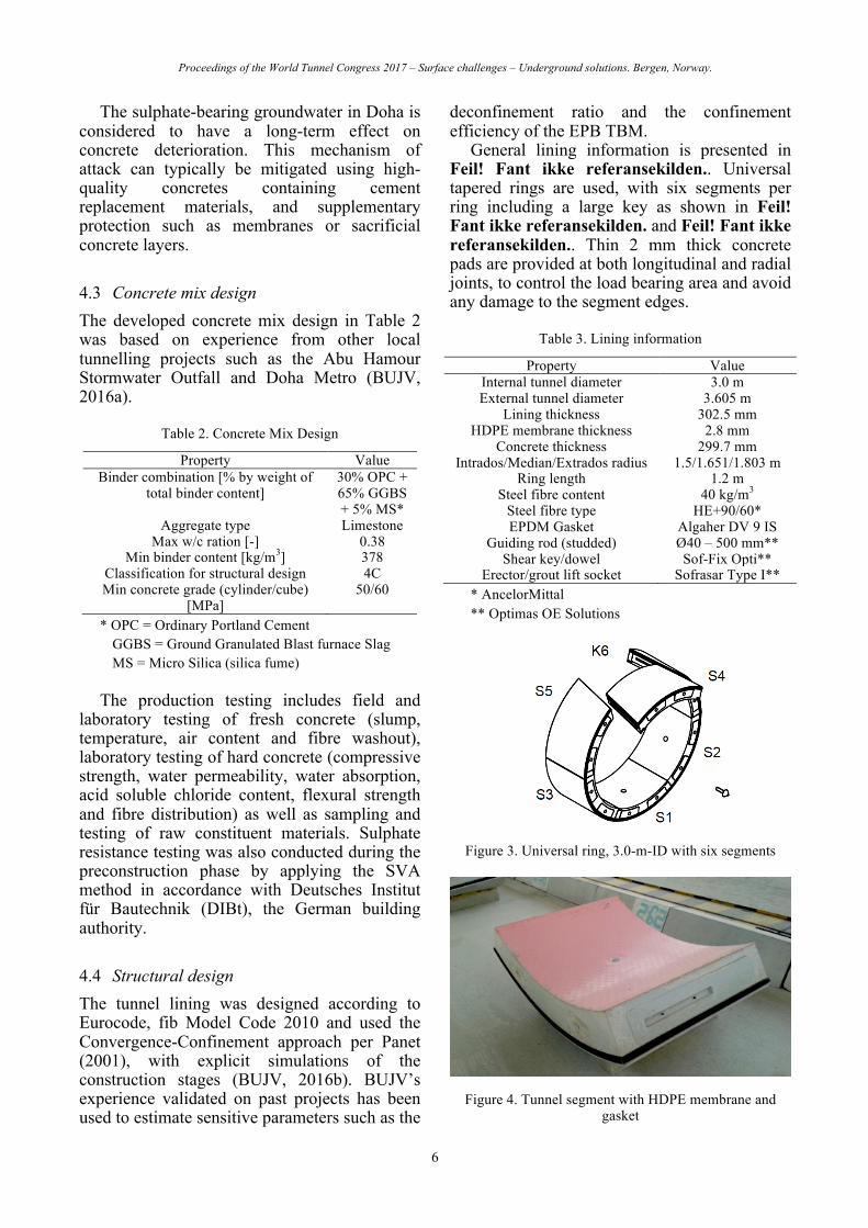
General lining information is presented in Feil! Fant ikke referansekilden.. Universal tapered rings are used, with six segments per ring including a large key as shown in Feil! Fant ikke referansekilden. and Feil! Fant ikke referansekilden.. Thin 2 mm thick concrete pads are provided at both longitudinal and radial joints, to control the load bearing area and avoid any damage to the segment edges.
Table 3. Lining information
Property Value Internal tunnel diameter 3.0 m External tunnel diameter 3.605 m
Lining thickness 302.5 mm HDPE membrane thickness 2.8 mm
Concrete thickness 299.7 mm Intrados/Median/Extrados radius 1.5/1.651/1.803 m
Ring length 1.2 m Steel fibre content 40 kg/m3
Steel fibre type HE+90/60* EPDM Gasket Algaher DV 9 IS
Guiding rod (studded) Ø40 – 500 mm** Shear key/dowel Sof-Fix Opti**
Erector/grout lift socket Sofrasar Type I** * AncelorMittal ** Optimas OE Solutions
Figure 3. Universal ring, 3.0-m-ID with six segments
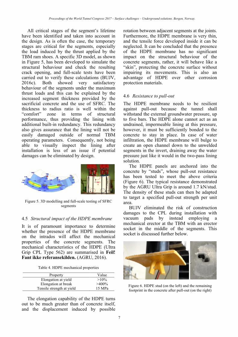
Figure 4. Tunnel segment with HDPE membrane and
gasket
Proceedings of the World Tunnel Congress 2017 – Surface challenges – Underground solutions. Bergen, Norway.
7
All critical stages of the segment’s lifetime have been identified and taken into account in the design. As is often the case, the temporary stages are critical for the segments, especially the load induced by the thrust applied by the TBM ram shoes. A specific 3D model, as shown in Figure 5, has been developed to simulate the structural behaviour and check the resulting crack opening, and full-scale tests have been carried out to verify these calculations (BUJV, 2016c). Both showed very satisfactory behaviour of the segments under the maximum thrust loads and this can be explained by the increased segment thickness provided by the sacrificial concrete and the use of SFRC. The thickness to radius ratio is well within the “comfort” zone in terms of structural performance, thus providing the lining with additional built-in redundancy. This redundancy also gives assurance that the lining will not be easily damaged outside of normal TBM operating parameters. Consequently, not being able to visually inspect the lining after installation is less of an issue if potential damages can be eliminated by design.
Figure 5. 3D modelling and full-scale testing of SFRC
segments
4.5 Structural impact of the HDPE membrane It is of paramount importance to determine whether the presence of the HDPE membrane on the intrados will affect the mechanical properties of the concrete segments. The mechanical characteristics of the HDPE (Ultra Grip CPL Type 562) are summarised in Feil! Fant ikke referansekilden. (AGRU, 2016).
Table 4. HDPE mechanical properties
Property Value Elongation at yield >10% Elongation at break >400%
Tensile strength at yield 15 MPa The elongation capability of the HDPE turns
out to be much greater than of concrete itself, and the displacement induced by possible
rotation between adjacent segments at the joints. Furthermore, the HDPE membrane is very thin, and the tensile force developed inside it can be neglected. It can be concluded that the presence of the HDPE membrane has no significant impact on the structural behaviour of the concrete segments, rather, it will behave like a “skin”, protecting the concrete surface without impairing its movements. This is also an advantage of HDPE over other corrosion protection materials.
4.6 Resistance to pull-out The HDPE membrane needs to be resilient against pull-out because the tunnel shall withstand the external groundwater pressure, up to five bars. The HDPE alone cannot act as an undrained, impermeable lining at this pressure, however, it must be sufficiently bonded to the concrete to stay in place. In case of water infiltration, the HDPE membrane will bulge to create an open channel down to the unwelded segments in the invert, draining away the water pressure just like it would in the two-pass lining solution.
The HDPE panels are anchored into the concrete by “studs”, whose pull-out resistance has been tested to meet the above criteria (Figure 6). The typical resistance demonstrated by the AGRU Ultra Grip is around 1.7 kN/stud. The density of these studs can then be adapted to target a specified pull-out strength per unit area.
BUJV eliminated the risk of construction damages to the CPL during installation with vacuum pads by instead employing a mechanical erector at the TBM with an erector socket in the middle of the segments. This socket is discussed further below.
Figure 6. HDPE stud (on the left) and the remaining footprint in the concrete after pull-out (on the right)

Proceedings of the World Tunnel Congress 2017 – Surface challenges – Underground solutions. Bergen, Norway.
8
4.7 Joints and gaskets The EPDM gasket was designed to withstand the groundwater pressure for 100 years at a 10 mm offset and installation tolerance of ±3 mm.
The gasket is located at the extrados of the ring, whereas the HDPE will be welded on the intrados, protecting the gasket from H2S attack, however, the gasket can still withstand some corrosive sewage gas exposure.
A one-piece embedded gasket type was chosen from Algaher, minimising placement discrepancies and keeping it securely in place during handling and installation.
5 MANUFACTURING OF THE SEGMENTS 5.1 Precast factory All 80,000 segments are manufactured in an in-house precast factory designed, equipped and operated by BUJV, including the concrete batching plant, which offers complete control on the quality of the SFRC. Thirteen sets of six moulds are used to cast an average of 160 segments per day.
5.2 Preconstruction trials Prior to full scale segment manufacturing, preconstruction trials took place to confirm the segment dimensions, concrete workability, the compaction of the concrete in the mould, the finish of the top and lateral walls and the distribution of the fibres. Thermocouples were also installed in the segments to measure the temperature development at the centre of the hardening concrete of the segment so it would not reach more than 75°C.
Furthermore, two segments were sent to France for crack monitoring and two segments were sent to Italy for TBM thrust load testing.
5.3 Segment manufacturing To tailor the HDPE panels to each of the six different segment geometries, templates are used for cutting as shown in Figure 7, considering the periodic fluctuations of the temperature to keep the dimensions within the tolerances.
The HDPE panel is then placed in the segment mould, after the erector socket (also made of HDPE) has been hot-welded at the centre.
Other embedded items such as the gasket, guiding rod studs and bolt sockets are also placed in the mould prior to placement of concrete.
Demoulding takes place after 7 hours when a minimum early age strength of 15 MPa is achieved.
Figure 7. Cutting of HDPE panels
5.4 Impact of HDPE on segment manufacturing The presence of the HDPE membrane on the intrados brings a few additional constraints to the segment production, whose impact shall not be overlooked since the quality of the final product depends on it.
The first obvious constraint is that the HDPE must not be damaged from the de-moulding operation all the way to the erection in the tunnel. All critical stages of the segment’s lifetime have been identified, for which adequate measures have been implemented to protect the membrane. For instance, “engravement tests” have been carried out to assess the residual deformation (reduction in thickness, measured with a micrometer) of the HDPE due to the stacking of the segments (Figure 8).
The presence of the HDPE membrane on the manufacturing of the segments does not bring unsurpassable problems. It requires however extra attention in terms of quality control (QC) in form of inspections, tracking with the use of bar coding and strict enforcement of designer guidelines at each and every production step to preserve the good condition of the lining. Nonetheless, the elevated levels of QC and oversight have been vital in achieving the required quality but at the same time kept the segment rejection rate and repairs to a minimum.

Proceedings of the World Tunnel Congress 2017 – Surface challenges – Underground solutions. Bergen, Norway.
9
Figure 8. “Engravement” tests linked to the stacking of
segments
6 INSTALLATION IN THE TUNNEL 6.1 Handling and erection The TBMs are equipped with a mechanical erector, holding the segments with a screw that is inserted into the HDPE socket. The HDPE socket (model Sofrasar grout lift socket type I), is embedded in the segments (Feil! Fant ikke referansekilden.) and its adaptor is welded to the membrane to ensure continuity of the CPL.
The erection process does not induce any significant load on the HDPE membrane, since the socket transfers the force directly to the much stiffer concrete.
Figure 9. Erector socket and HDPE panel in the mould
prior to concreting
6.2 Welding of the joints The total cumulated length of all joints over the 16 km of tunnel is approximately 250 km, which justifies the search for optimised welding equipment and techniques. Therefore, BUJV built a mock-up of the tunnel consisting of eight rings to develop and test the welding system before commencing the tunnelling operations.
At each joint located above the bottom 30-degree angle in the tunnel, extrusion welding as shown in Figure 10 is performed, to recreate a continuous, interruption-free CPL (Figure 11). Qualified welders perform the first phase of the
welding from a gantry at the back of the TBM, while the second phase is carried out after demobilisation of the TBM.
The integrity of the all seams is verified by spark testing.
Figure 10. HDPE extrusion welding
Figure 11. CPL after welding
6.3 Other construction activities To minimise any damage to the lining during tunnel excavation, BUJV developed special brackets for hanging the TBM services, and these attach to the erector socket. Furthermore, any secondary grouting can also be performed through the sockets.
In addition, special testing by Herrenknecht shown in Figure 12, has been carried out to ensure that the loads imposed by the TBM bogies onto the lining do not cause excessive permanent engravement.
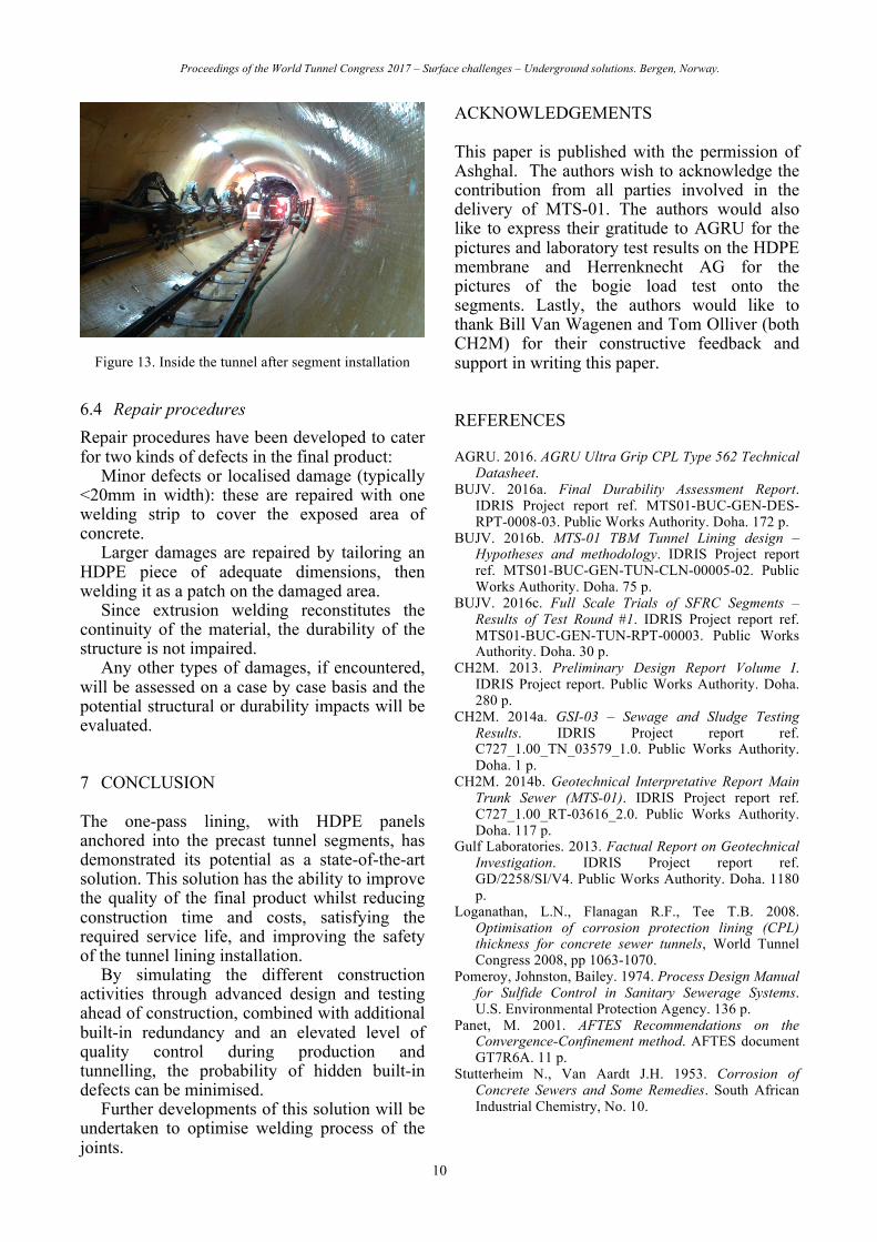
Figure 13 shows the inside of the tunnel after segment installation, which had just commenced at the time of finalising this paper.
Figure 12. Tests for the bogie loading
Proceedings of the World Tunnel Congress 2017 – Surface challenges – Underground solutions. Bergen, Norway.
10
Figure 13. Inside the tunnel after segment installation
6.4 Repair procedures Repair procedures have been developed to cater for two kinds of defects in the final product:
Minor defects or localised damage (typically <20mm in width): these are repaired with one welding strip to cover the exposed area of concrete.
Larger damages are repaired by tailoring an HDPE piece of adequate dimensions, then welding it as a patch on the damaged area.
Since extrusion welding reconstitutes the continuity of the material, the durability of the structure is not impaired.
Any other types of damages, if encountered, will be assessed on a case by case basis and the potential structural or durability impacts will be evaluated.
7 CONCLUSION
The one-pass lining, with HDPE panels anchored into the precast tunnel segments, has demonstrated its potential as a state-of-the-art solution. This solution has the ability to improve the quality of the final product whilst reducing construction time and costs, satisfying the required service life, and improving the safety of the tunnel lining installation.
By simulating the different construction activities through advanced design and testing ahead of construction, combined with additional built-in redundancy and an elevated level of quality control during production and tunnelling, the probability of hidden built-in defects can be minimised.
Further developments of this solution will be undertaken to optimise welding process of the joints.
ACKNOWLEDGEMENTS
This paper is published with the permission of Ashghal. The authors wish to acknowledge the contribution from all parties involved in the delivery of MTS-01. The authors would also like to express their gratitude to AGRU for the pictures and laboratory test results on the HDPE membrane and Herrenknecht AG for the pictures of the bogie load test onto the segments. Lastly, the authors would like to thank Bill Van Wagenen and Tom Olliver (both CH2M) for their constructive feedback and support in writing this paper.
REFERENCES
AGRU. 2016. AGRU Ultra Grip CPL Type 562 Technical Datasheet.
BUJV. 2016a. Final Durability Assessment Report. IDRIS Project report ref. MTS01-BUC-GEN-DES-RPT-0008-03. Public Works Authority. Doha. 172 p.
BUJV. 2016b. MTS-01 TBM Tunnel Lining design – Hypotheses and methodology. IDRIS Project report ref. MTS01-BUC-GEN-TUN-CLN-00005-02. Public Works Authority. Doha. 75 p.
BUJV. 2016c. Full Scale Trials of SFRC Segments – Results of Test Round #1. IDRIS Project report ref. MTS01-BUC-GEN-TUN-RPT-00003. Public Works Authority. Doha. 30 p.
CH2M. 2013. Preliminary Design Report Volume I. IDRIS Project report. Public Works Authority. Doha. 280 p.
CH2M. 2014a. GSI-03 – Sewage and Sludge Testing Results. IDRIS Project report ref. C727_1.00_TN_03579_1.0. Public Works Authority. Doha. 1 p.
CH2M. 2014b. Geotechnical Interpretative Report Main Trunk Sewer (MTS-01). IDRIS Project report ref. C727_1.00_RT-03616_2.0. Public Works Authority. Doha. 117 p.
Gulf Laboratories. 2013. Factual Report on Geotechnical Investigation. IDRIS Project report ref. GD/2258/SI/V4. Public Works Authority. Doha. 1180 p.
Loganathan, L.N., Flanagan R.F., Tee T.B. 2008. Optimisation of corrosion protection lining (CPL) thickness for concrete sewer tunnels, World Tunnel Congress 2008, pp 1063-1070.
Pomeroy, Johnston, Bailey. 1974. Process Design Manual for Sulfide Control in Sanitary Sewerage Systems. U.S. Environmental Protection Agency. 136 p.
Panet, M. 2001. AFTES Recommendations on the Convergence-Confinement method. AFTES document GT7R6A. 11 p.
Stutterheim N., Van Aardt J.H. 1953. Corrosion of Concrete Sewers and Some Remedies. South African Industrial Chemistry, No. 10.