Innovative MCS Starter Solutions - Solar Danmark A/Slegacy.solar.dk/upload/downloads/industri/ab_mcs...
54
WELCOME TO THE WORLD OF COMPLETE AUTOMATION Innovative MCS Starter Solutions MCS Starters and the New Mounting System 141A
Transcript of Innovative MCS Starter Solutions - Solar Danmark A/Slegacy.solar.dk/upload/downloads/industri/ab_mcs...

WELCOME TO THE WORLD OF COMPLETE AUTOMATION
Innovative MCS Starter Solutions
MCS Starters and the New Mounting System 141A

Open
Enclosed
Busbar
Top-hat rail
Panel
MotorProtection
Performance
Application
SafetyStandards
Control
Maintenance
SMC-DeltaSMC-3
Welcome to the Wide World of Allen-Bradley Starters
Innovative solutions for state of the art power control equipmentModern industrial automation requires efficient systems for power control, dependingon the specific application. Rockwell Automation offers tailored solutionsfor all purposes:
• MCS electromechanical starters for economic applications, as shown in this publication
• Electromechanical starters and loadfeeders up to 1250 A, see Catalogue A114-CA001A
• SMC softstarters for controlled starting and stopping of motors, see Selection Guide 150-SG006A
• PowerFlex 4 AC variable speed drives for continuous process control, see Technical Data 22A-TD001A
Power control devices integrate into control systemsAllen-Bradley motor control devices integrate into all kinds of control systems and architectures:
• Electromechanical control
• PLC control
• Industrial PC control
• DeviceNet bus communication control systems
Motor protection tailored to the application needsRockwell Automation offers a wide choice of Allen-Bradley motor protectiondevices for optimal protection, matching the application needs:
• 140M motor protection circuit breakers for cost-optimized solutions
• 193E electronic overload relays for enhanced up to high-levelprotection purposes including monitoring functions
• Integrated motor protection of softstarters and variable speed drives
Different applications require different mechanical structuresThe optimal mechanical system structure depends on the application, the system size, the control structure, and the required system availability.Rockwell Automation offers the right solution for all requirements, whether:
• Open or enclosed
• Busbar mounted
• Top-hat rail mounted
• Panel mounted
New Mounting System 141A offers MCC features at unmatched cost • Modular system design assures flexibility for extensions and changes in function
• Exchangeable starters and load feeders reduce downtime and provide flexibility
• Pluggable connections minimize wiring expenditure
• Operator safety provided by full protection against electric shock
2
InSaWinnToday’sinto thechangiand in Plant-fphases
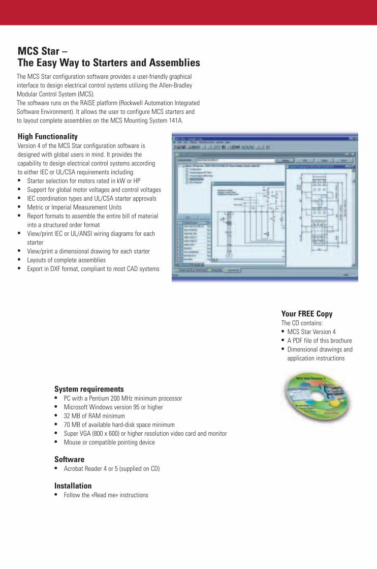
MCS Star –The Easy Way to Starters and Assemblies
High FunctionalityVersion 4 of the MCS Star configuration software is designed with global users in mind. It provides the capability to design electrical control systems according to either IEC or UL/CSA requirements including:• Starter selection for motors rated in kW or HP• Support for global motor voltages and control voltages• IEC coordination types and UL/CSA starter approvals• Metric or Imperial Measurement Units• Report formats to assemble the entire bill of material
into a structured order format• View/print IEC or UL/ANSI wiring diagrams for each
starter• View/print a dimensional drawing for each starter • Layouts of complete assemblies• Export in DXF format, compliant to most CAD systems
Main• Sim
pre
• Typcomcon
• Sequi
• Isosyssys
Your FREE Copy The CD contains:• MCS Star Version 4• A PDF file of this brochure • Dimensional drawings and
application instructions
System requirements• PC with a Pentium 200 MHz minimum processor • Microsoft Windows version 95 or higher • 32 MB of RAM minimum• 70 MB of available hard-disk space minimum • Super VGA (800 x 600) or higher resolution video card and monitor • Mouse or compatible pointing device
Software• Acrobat Reader 4 or 5 (supplied on CD)
Installation• Follow the «Read me» instructions
The MCS Star configuration software provides a user-friendly graphicalinterface to design electrical control systems utilizing the Allen-BradleyModular Control System (MCS).The software runs on the RAISE platform (Rockwell Automation IntegratedSoftware Environment). It allows the user to configure MCS starters andto layout complete assemblies on the MCS Mounting System 141A.

2
Innovative Starter Solutions –Savings and Benefits in all Phases
Innovative starter solutions from Rockwell Automation are offering benefits in every phase of the life cycle and help to maximize your investment. Lower total cost of ownershipwill be the result of choosing Rockwell Automation and it’s starter solutions.
Winning the challenge of the marketToday’s manufacturers are forced to integrate greater flexibilityinto their systems and production equipment to meet the ever-changing customer demands for better products at reduced costand in less time.Plant-floor automation has become a dynamic cycle with thephases: Justify – Apply – Install – Operate – Maintain – Improve.
Maintain• Simple starter exchange permits quick and efficient
preventive maintenance where required.
• Type “2” coordinated starters allow you to exchange components after a short-circuit at an operationally convenient point of time.
• Selective status signalling enable users to trace failures quickly.
• Iso™ Modules allow safe starter exchange during normal system operation and without switching-off the completesystem.
Operate• Reliable products guarantee trouble-free operation.
• Signalling and monitoring functions, e.g. running load with MCS-E3, permit optimized productivity and quick failure tracing.
• Efficient protection features avoid shut down and damages, increase the productivity.
Improve• Rapid and easy system extensions with busbar
mounting system.
• Future extensions can easily be considered from the beginning by using MCS Star.
• System flexibility allows for re-use of starter assemblies in other applications with different control functionality or motor sizes.
InstallStarters based on the Mounting System 141A are easy toinstall, time- and cost-saving. The advantages thereby are:
• Pluggable control connections available.
• Complete starters plug onto the bus bars.
• Simple starter exchange for commissioning.
• Test position for functional check of the control circuitrywith main circuits open.
3
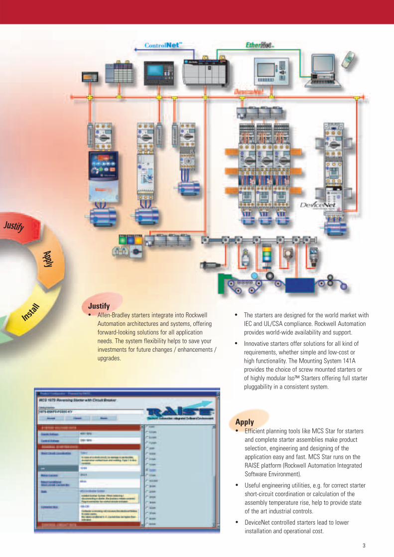
• The starters are designed for the world market withIEC and UL/CSA compliance. Rockwell Automation provides world-wide availability and support.
• Innovative starters offer solutions for all kind of requirements, whether simple and low-cost or high functionality. The Mounting System 141A provides the choice of screw mounted starters or of highly modular Iso™ Starters offering full starter pluggability in a consistent system.
Apply• Efficient planning tools like MCS Star for starters
and complete starter assemblies make product selection, engineering and designing of the application easy and fast. MCS Star runs on the RAISE platform (Rockwell Automation Integrated Software Environment).
• Useful engineering utilities, e.g. for correct starter short-circuit coordination or calculation of the assembly temperature rise, help to provide state of the art industrial controls.
• DeviceNet controlled starters lead to lower installation and operational cost.
Justify• Allen-Bradley starters integrate into Rockwell
Automation architectures and systems, offering forward-looking solutions for all application needs. The system flexibility helps to save your investments for future changes / enhancements / upgrades.

4
Pluggable modules• Standard and Iso™ Modules can be plugged as complete units
onto 60 mm centre spaced busbar systems.
• Simple mounting, commissioning and exchange of complete and prewired modules/load feeders.
• No drilling of holes for conductor connections, no screwing etc.• High reliability of busbar contacts – extends type “2” coordina-
tion to complete starter units mounted onto busbars.
Are you looking for MCC-features?The new Mounting System 141A offers them atunmatched cost
Compliant to high standards• Separation of busbars from the functional units with terminals
separated from busbars provides safety in operation and handling, corresponding to form 2b.
• All components of the starters are type-tested according EN 60 947 and fulfill the demanding standards. This facilitatesthe realisation of partially type-tested switchgear and control-gear assemblies in compliance with EN 60 439-1.
• For more information, see also our publication PTSK EN:“The easy way to build switchgear and controlgear assembliesin compliance with the regulations”
Ready for up-to-date control techniques• Ideally suited for decentralized control systems installed
in small local control stations.
• Suitable for conventional control as well as for PLC, DeviceNet and other field bus control.
• Vertical busbar orientation possible for space saving assemblies e.g. with direct connection of field wiring to the starters and load feeders.
The New Low-Cost Motor Control Centre Alternative
Standard Iso™ Busbar Busbar
Modules Modules The ease of flexibility• Free combination of load feeders • •• Use of standard preengineered starters as
• •well as of specific ones
The freedom of modularity • Easy to plan • •• Easy to order, one catalogue number for a
• •complete starter
• Easy to build • •• Easy in commissioning • •• Easy in holding spare parts • •• Easy for extensions and updates • •The speed of change
• Modules pluggable onto busbars • •• Control circuits pluggable as option • -• Control circuits pluggable as standard - •• Simple and quick mounting • •• Quick failure tracing and exchange lead to
• •low down-times and high productivity
The benefits of the test position• Safe and easy in commissioning and failure tracing - •• Full functional checks possible with the
•main circuits open -The comfort of safety
• No risk of electric shock when•starters are removed. No accessible live parts -
• Automatic contactor drop-out when removing•load-feeders (option) -
• No verification of short-circuit withstandrequired with highly current limiting • •circuit breakers series 140M and 140-CMN
• Circuit breakers 140M and 140-CMN withisolating and padlocking capability for • •disconnecting loads
MCS Iso™ Busbar Module
MCS StandardBusbar Module

Iso™ Modules for increased safety and functionality• Starter units plug on top of the busbar modules, which keep
the busbars safely covered.
• Control plugs standard.
• Test position for testing of the control circuits without load current flowing.
• Optional microswitch that automatically drops out the contactor when moving the module into the test position.
No verification of short-circuit withstandstrength with highly current limiting circuit breakers 140M and 140-CMN • IEC 60 439-1 dispenses from verification for Ipk < 17 kA.
140M and 140-CMN limit s-c currents well below this level.
• Starters using 140M Circuit Breakers, which fulfill UL 508 Type Erequirements as Manual Self-Protected Combination Motor Controllers, have no special limitation on the number of load feeders connected to an upstream SCPD� special Group MotorRules governing tap conductor protection no longer apply to these starters.
FlexibilityFree combination of loadfeeders and starters
ExchangeFast, easy and safe exchange of starters
Test PositionFull functional tests withthe main circuit open
5
6
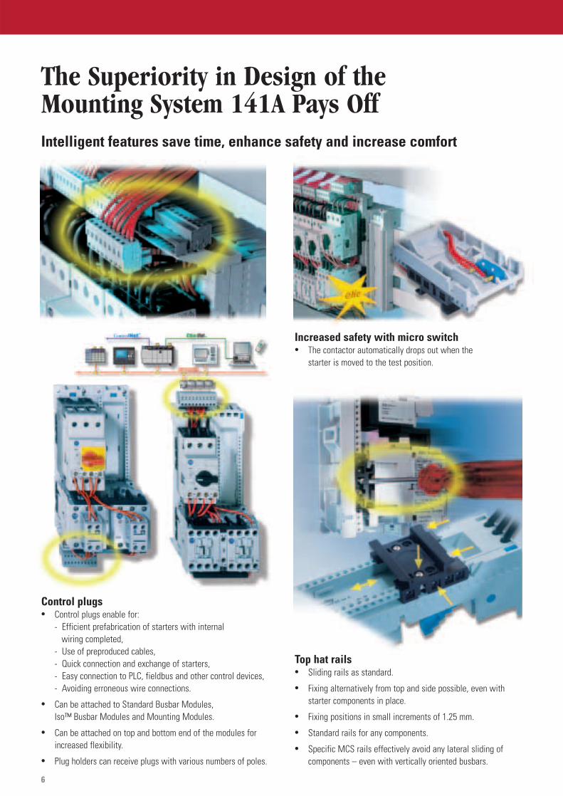
The Superiority in Design of the Mounting System 141A Pays Off
Control plugs• Control plugs enable for:
- Efficient prefabrication of starters with internal wiring completed,
- Use of preproduced cables,- Quick connection and exchange of starters,- Easy connection to PLC, fieldbus and other control devices,- Avoiding erroneous wire connections.
• Can be attached to Standard Busbar Modules, Iso™ Busbar Modules and Mounting Modules.
• Can be attached on top and bottom end of the modules for increased flexibility.
• Plug holders can receive plugs with various numbers of poles.
Increased safety with micro switch• The contactor automatically drops out when the
starter is moved to the test position.
Top hat rails• Sliding rails as standard.
• Fixing alternatively from top and side possible, even with starter components in place.
• Fixing positions in small increments of 1.25 mm.
• Standard rails for any components.
• Specific MCS rails effectively avoid any lateral sliding of components – even with vertically oriented busbars.
Intelligent features save time, enhance safety and increase comfort

7
Spare space busbar covers for operator safety• Covers for single busbars, can be cut to required length.
• Three pole busbar shroud for covering complete spare places.
New supply module for simple and safe supply• 3-phase units in one piece.
• Modern box-type terminals.
• Feeding-through possible.
Big cross-sections for thermally safe systems• Particularly important for systems operating at increased
ambient temperature conditions.
Bigger starter platforms by attaching modulesside-by-side• Simply insert connection clips from the rear to combine
modules.
5 mm
10 mm
Modules suitable for 5 mm and 10 mm busbars• One catalog number only.
• Set for 5 mm busbars upon delivery.
• Simple changeover to 10 mm busbar size by help of a screwdriver.
Latching busbar arresting lever• Keeps modules in place.
• Can be latched into open position to make both hands available for plugging-off modules (particularly important for load feeders consisting of two or more modules).

8
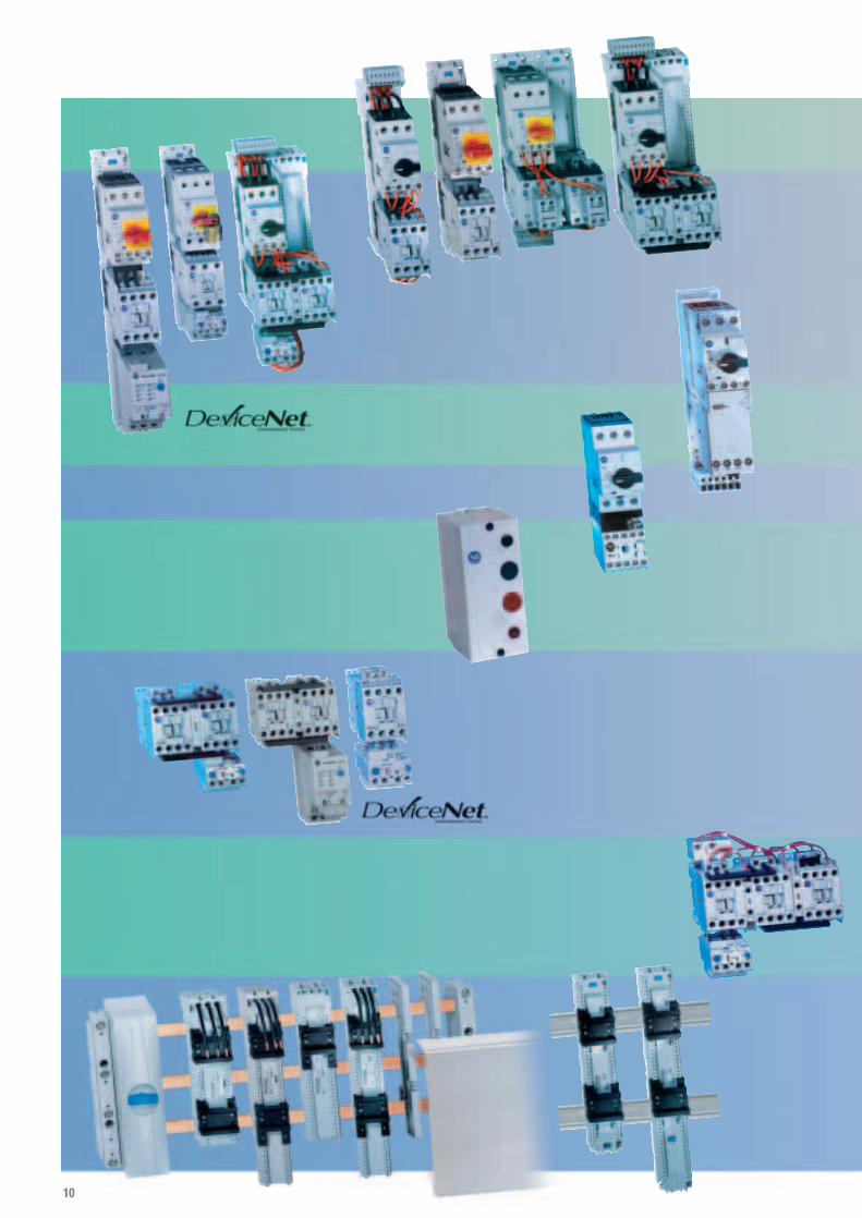
2-Component Direct On-Line Starter Bulletin 103S mounted on an MCS Iso™ Busbar Module
2-Component Reversing Starter Bulletin 107S mounted on an MCS Standard Busbar Module
3-Component Direct On-Line Starter Bulletin 103T mounted on an MCS Standard Busbar Module
3-Component Direct On-Line Starter Bulletin 103T mounted on an MCS Mounting Module for top-hat rail or screw mounting
2-Component Direct On-Line Compact Starter Bulletin 190S for top-hat rail or screw mounting
2-Component Direct On-Line Eco Starter Bulletin 190E for top-hat rail mounting
Enclosed Starter Bulletin 109 for screw mounting
Conventional Star-Delta Starter Bulletin 170 for top-hat rail or screw mounting
1
1
7
2
3
4
4
2
3
6
5
65
8
7
8
MCS Iso™ Busbar Module MCS Standard Busbar Modules
MCS Mounting Module
DeviceAdapter
Plate
Busbar Module
DOL Starters
ReversingStarters
Star-DeltaStarters
MotorProtectionCircuit Breaker
Magnetic OnlyCircuit Breaker
Electronicor ThermalOverload Relay
Type “2”
Busbarplug-on
Top-hat railmountingScrew mountingPluggable
9
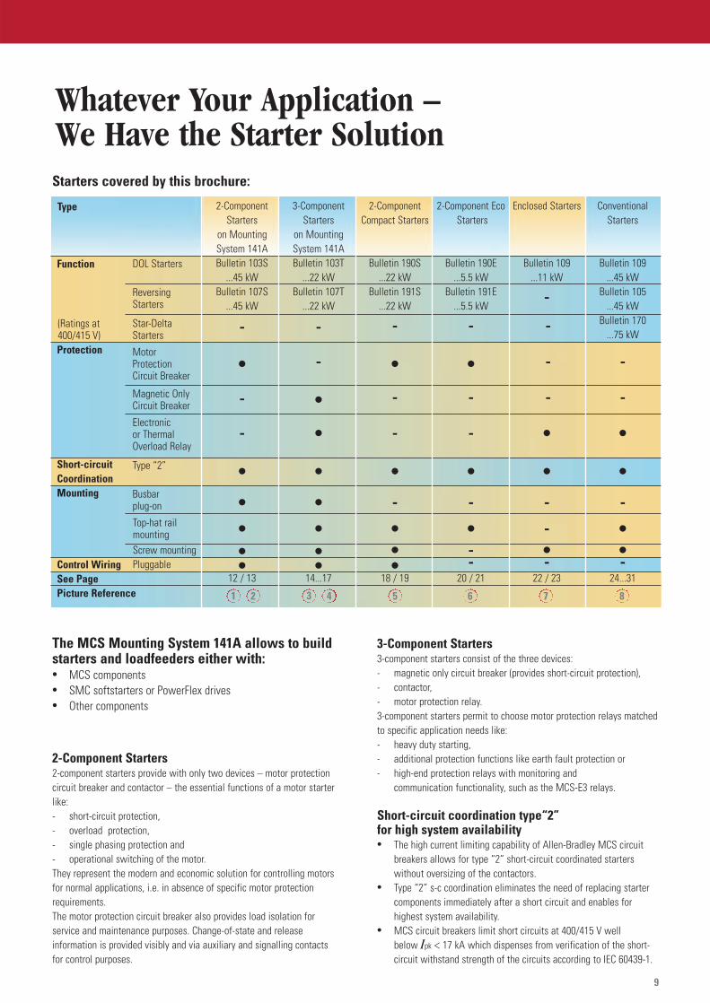
Whatever Your Application – We Have the Starter Solution
The MCS Mounting System 141A allows to buildstarters and loadfeeders either with:• MCS components • SMC softstarters or PowerFlex drives • Other components
2-Component Starters2-component starters provide with only two devices – motor protectioncircuit breaker and contactor – the essential functions of a motor starterlike:- short-circuit protection,- overload protection,- single phasing protection and- operational switching of the motor. They represent the modern and economic solution for controlling motorsfor normal applications, i.e. in absence of specific motor protectionrequirements.The motor protection circuit breaker also provides load isolation for service and maintenance purposes. Change-of-state and release information is provided visibly and via auxiliary and signalling contactsfor control purposes.
3-Component Starters3-component starters consist of the three devices:- magnetic only circuit breaker (provides short-circuit protection),- contactor,- motor protection relay.3-component starters permit to choose motor protection relays matched to specific application needs like:- heavy duty starting,- additional protection functions like earth fault protection or- high-end protection relays with monitoring and
communication functionality, such as the MCS-E3 relays.
Short-circuit coordination type“2” for high system availability• The high current limiting capability of Allen-Bradley MCS circuit
breakers allows for type “2” short-circuit coordinated starters without oversizing of the contactors.
• Type “2” s-c coordination eliminates the need of replacing starter components immediately after a short circuit and enables for highest system availability.
• MCS circuit breakers limit short circuits at 400/415 V well below Ipk < 17 kA which dispenses from verification of the short-circuit withstand strength of the circuits according to IEC 60439-1.
2-ComponentStarters
on MountingSystem 141ABulletin 103S
...45 kWBulletin 107S
...45 kW
-
•-
-
•••••
12 / 13
3-ComponentStarters
on MountingSystem 141ABulletin 103T
...22 kWBulletin 107T
...22 kW
-
-
••
•••••
14...17
2-ComponentCompact Starters
Bulletin 190S...22 kW
Bulletin 191S...22 kW
-
•-
-
•-
•••
18 / 19
2-Component EcoStarters
Bulletin 190E...5.5 kW
Bulletin 191E...5.5 kW
-
•-
-
•-
•--
20 / 21
ConventionalStarters
Bulletin 109...45 kW
Bulletin 105...45 kW
Bulletin 170...75 kW
-
-
•
•-
••-
24...31
Enclosed Starters
Bulletin 109...11 kW
-
-
-
-
•
•-
-•-
22 / 23
Type
Function
Protection
Short-circuitCoordinationMounting
Control WiringSee PagePicture Reference
Starters covered by this brochure:
1 3 5 6 7 82 4
(Ratings at400/415 V)
110

11
Bulletin 103S / 107S • Direct On-Line / Reversing Starters Pages with Circuit Breaker on Mounting System 141A 12 ... 13
Bulletin 103T / 107T • Direct On-Line / Reversing Starters Pageswith Circuit Breaker and 14 ... 15Electronic Overload Relay 193-EAon Mounting System 141A
• Direct On-Line / Reversing Starters Pageswith Circuit Breaker and 16 ... 17Electronic Motor Protection Relay 193-ECon Mounting System 141A
Bulletin 190S / 191S • Compact Starters Pages18 ... 19
Bulletin 190E / 191E • Eco Starters Pages20 ... 21
Bulletin 109 • Starters in Plastic Enclosure Pageswith Electronic Overload Relay 22 ... 23
• Starters in Plastic Enclosure Pageswith Thermal Overload Relay 22 ... 23
Bulletin 109 / 105 • Direct On-Line / Reversing Starters Pageswith Electronic Overload Relay 193-EA 24 ... 25
• Direct On-Line / Reversing Starters Pageswith Electronic Motor Protection Relay 193-EC 26 ... 27
• Direct On-Line / Reversing Starters Pageswith Thermal Overload Relay 193-CT 28 ... 29
Bulletin 170 • Star-Delta Starters Pageswith Electronic Overload Relay 193-EA 30 ... 31
• Star-Delta Starters Pageswith Thermal Overload Relay 193-CT 30 ... 31
Bulletin 141A • Mounting System 141A Pages33 ... 42

12 Rockwell Automation
Bulletin 103S / 107SStarters with Circuit BreakerProduct Selection
2-Component Direct On-Line Starters / Reversing Starters • Short-Circuit Coordination Type "1" and "2" according to IEC 60947-4-1• Starters with Bulletin 140M or 140-CMN circuit breakers and 100-C contactors• Completely assembled and wired on Bulletin 141A mounting system• IEC and UL/CSA compliant• Mounting versions: please refer to pages 8 and 9
T - MCS Standard Busbar Module, pluggable on busbar systems with 60 mm pole centre spacing
S - MCS IsoTM Busbar Module, pluggable on busbar systems with 60 mm polecentre spacing
W - Snap on 2 top hat rails 35 mm / 1 top hat rail 75 mm or screw fixing
Note: Line voltage and short-circuit coordination see MCS Star or catalog A114Selection: Find the correct Index Number considering motor rating, line voltage and coordination type
Standard MotorsAC-3, 3phase
230 V 400 / 415 V 500 V 690 VType 1 Type 2 Type 1 Type 2 Type 1 Type 2 Type 1 Type 2
[kW] Index Iq [kA] Index Iq [kA] Index Iq [kA] Index Iq [kA] Index Iq [kA] Index Iq [kA] Index Iq [kA] Index Iq [kA]0.02 02 100 02 65 01 100 01 650.04 03 100 03 65 02 100 02 650.06 04 100 04 65 02 100 02 65 02 100 02 50 01 100 01 500.09 04 100 04 65 03 100 03 65 03 100 03 50 02 100 02 500.12 05 100 05 65 04 100 04 65 03 100 03 50 03 100 03 500.18 06 100 06 65 04 100 04 65 04 100 04 50 03 100 03 500.25 06 100 06 65 05 100 05 65 05 100 05 50 04 100 04 500.37 07 100 07 65 06 100 06 65 05 100 05 50 05 100 05 500.55 08 100 08 50 06 100 06 65 06 100 06 50 05 100 05 500.75 08 100 08 50 07 100 07 65 06 100 06 50 06 10 06 81.1 11 100 11 50 08 100 08 50 07 100 07 50 06 10 06 81.5 11 100 11 50 08 100 08 50 08 100 09 50 07 8 07 81.8 14 100 14 50 11 100 11 50 08 100 09 50 07 8 07 82.2 14 100 14 50 11 100 11 50 08 100 09 50 08 8 10 103.0 20 100 20 50 14 100 14 50 11 100 12 50 08 8 10 103.7 21 100 21 50 14 100 14 50 14 50 15 50 12 10 13 104.0 21 100 21 50 14 100 14 50 14 50 15 50 12 10 13 105.5 26 50 27 65 20 65 20 50 16 50 17 50 17 6 19 66.3 30 50 31 65 21 65 21 50 22 50 22 50 18 6 19 67.5 36 100 36 65 21 65 21 50 22 50 22 50 18 6 19 69.0 37 100 37 65 26 50 27 65 24 50 24 50 24 6 25 6
10.0 40 100 40 65 30 50 31 65 27 50 29 50 24 6 25 611.0 41 100 41 65 30 50 31 65 27 50 29 50 25 6 25 613.0 41 100 41 65 36 65 36 65 31 50 34 50 25 6 25 615.0 44 100 44 65 36 65 36 65 32 50 34 50 28 6 28 617.0 44 100 44 65 40 65 40 65 37 50 37 50 33 10 33 618.5 44 100 44 65 40 65 40 65 37 50 37 50 33 10 33 620 47 100 47 65 41 65 41 65 37 50 38 50 35 10 35 622 47 100 47 65 41 65 41 65 41 50 41 50 38 10 38 625 48 100 48 65 44 65 44 65 41 50 41 50 39 10 39 630 44 65 44 65 42 50 42 50 42 10 42 632 44 65 44 65 44 50 44 30 42 10 42 637 47 50 47 65 44 50 44 30 43 10 43 640 48 50 48 65 45 50 45 15 43 10 43 645 48 50 48 65 47 50 47 15 46 850 48 50 48 1555 48 50 48 15
103S… 107S…
Hp ratings and dimensions - see MCS Star
Rockwell Automation 13
Bulletin 103S / 107SStarters with Circuit Breaker
Product Selection
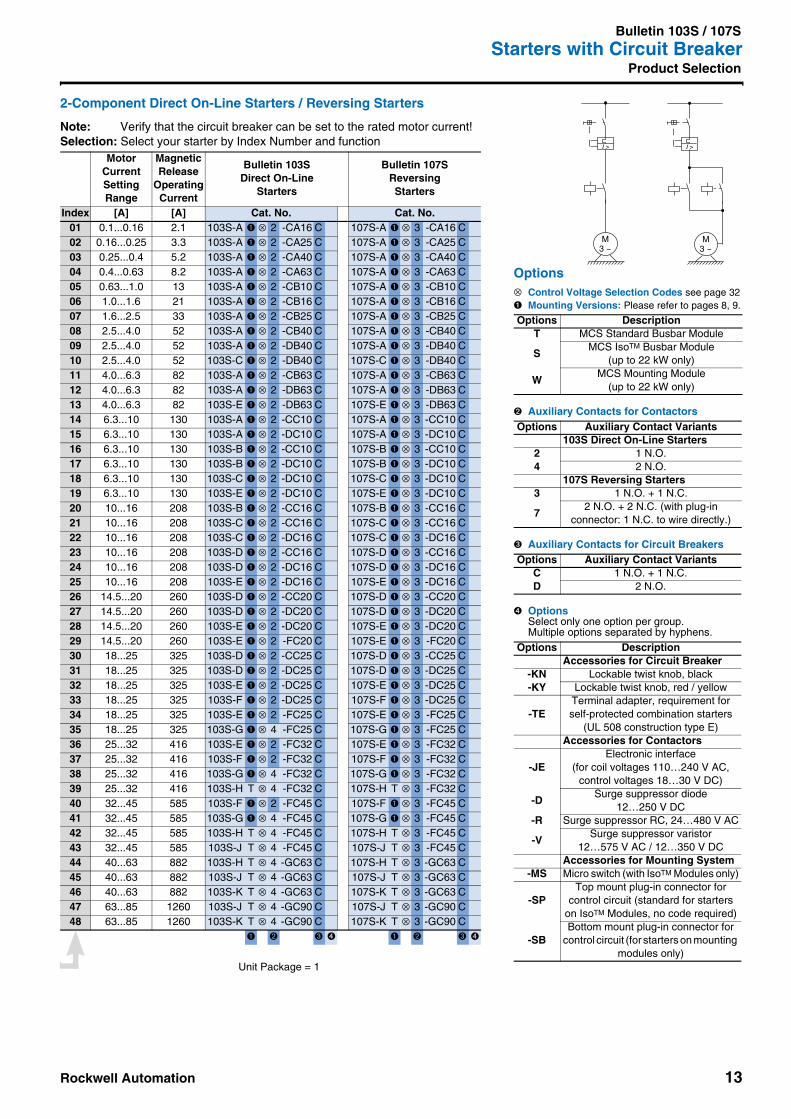
2-Component Direct On-Line Starters / Reversing Starters
Note: Verify that the circuit breaker can be set to the rated motor current!Selection: Select your starter by Index Number and function
Motor CurrentSettingRange
MagneticRelease
OperatingCurrent
Bulletin 103SDirect On-Line
Starters
Bulletin 107SReversingStarters
Index [A] [A] Cat. No. Cat. No.01 0.1...0.16 2.1 103S-A ➊ ⊗ 2 -CA16 C 107S-A ➊ ⊗ 3 -CA16 C02 0.16...0.25 3.3 103S-A ➊ ⊗ 2 -CA25 C 107S-A ➊ ⊗ 3 -CA25 C03 0.25...0.4 5.2 103S-A ➊ ⊗ 2 -CA40 C 107S-A ➊ ⊗ 3 -CA40 C04 0.4...0.63 8.2 103S-A ➊ ⊗ 2 -CA63 C 107S-A ➊ ⊗ 3 -CA63 C05 0.63...1.0 13 103S-A ➊ ⊗ 2 -CB10 C 107S-A ➊ ⊗ 3 -CB10 C06 1.0...1.6 21 103S-A ➊ ⊗ 2 -CB16 C 107S-A ➊ ⊗ 3 -CB16 C07 1.6...2.5 33 103S-A ➊ ⊗ 2 -CB25 C 107S-A ➊ ⊗ 3 -CB25 C08 2.5...4.0 52 103S-A ➊ ⊗ 2 -CB40 C 107S-A ➊ ⊗ 3 -CB40 C09 2.5...4.0 52 103S-A ➊ ⊗ 2 -DB40 C 107S-A ➊ ⊗ 3 -DB40 C10 2.5...4.0 52 103S-C ➊ ⊗ 2 -DB40 C 107S-C ➊ ⊗ 3 -DB40 C11 4.0...6.3 82 103S-A ➊ ⊗ 2 -CB63 C 107S-A ➊ ⊗ 3 -CB63 C12 4.0...6.3 82 103S-A ➊ ⊗ 2 -DB63 C 107S-A ➊ ⊗ 3 -DB63 C13 4.0...6.3 82 103S-E ➊ ⊗ 2 -DB63 C 107S-E ➊ ⊗ 3 -DB63 C14 6.3...10 130 103S-A ➊ ⊗ 2 -CC10 C 107S-A ➊ ⊗ 3 -CC10 C15 6.3...10 130 103S-A ➊ ⊗ 2 -DC10 C 107S-A ➊ ⊗ 3 -DC10 C16 6.3...10 130 103S-B ➊ ⊗ 2 -CC10 C 107S-B ➊ ⊗ 3 -CC10 C17 6.3...10 130 103S-B ➊ ⊗ 2 -DC10 C 107S-B ➊ ⊗ 3 -DC10 C18 6.3...10 130 103S-C ➊ ⊗ 2 -DC10 C 107S-C ➊ ⊗ 3 -DC10 C19 6.3...10 130 103S-E ➊ ⊗ 2 -DC10 C 107S-E ➊ ⊗ 3 -DC10 C20 10...16 208 103S-B ➊ ⊗ 2 -CC16 C 107S-B ➊ ⊗ 3 -CC16 C21 10...16 208 103S-C ➊ ⊗ 2 -CC16 C 107S-C ➊ ⊗ 3 -CC16 C22 10...16 208 103S-C ➊ ⊗ 2 -DC16 C 107S-C ➊ ⊗ 3 -DC16 C23 10...16 208 103S-D ➊ ⊗ 2 -CC16 C 107S-D ➊ ⊗ 3 -CC16 C24 10...16 208 103S-D ➊ ⊗ 2 -DC16 C 107S-D ➊ ⊗ 3 -DC16 C25 10...16 208 103S-E ➊ ⊗ 2 -DC16 C 107S-E ➊ ⊗ 3 -DC16 C26 14.5...20 260 103S-D ➊ ⊗ 2 -CC20 C 107S-D ➊ ⊗ 3 -CC20 C27 14.5...20 260 103S-D ➊ ⊗ 2 -DC20 C 107S-D ➊ ⊗ 3 -DC20 C28 14.5...20 260 103S-E ➊ ⊗ 2 -DC20 C 107S-E ➊ ⊗ 3 -DC20 C29 14.5...20 260 103S-E ➊ ⊗ 2 -FC20 C 107S-E ➊ ⊗ 3 -FC20 C30 18...25 325 103S-D ➊ ⊗ 2 -CC25 C 107S-D ➊ ⊗ 3 -CC25 C31 18...25 325 103S-D ➊ ⊗ 2 -DC25 C 107S-D ➊ ⊗ 3 -DC25 C32 18...25 325 103S-E ➊ ⊗ 2 -DC25 C 107S-E ➊ ⊗ 3 -DC25 C33 18...25 325 103S-F ➊ ⊗ 2 -DC25 C 107S-F ➊ ⊗ 3 -DC25 C34 18...25 325 103S-E ➊ ⊗ 2 -FC25 C 107S-E ➊ ⊗ 3 -FC25 C35 18...25 325 103S-G ➊ ⊗ 4 -FC25 C 107S-G ➊ ⊗ 3 -FC25 C36 25...32 416 103S-E ➊ ⊗ 2 -FC32 C 107S-E ➊ ⊗ 3 -FC32 C37 25...32 416 103S-F ➊ ⊗ 2 -FC32 C 107S-F ➊ ⊗ 3 -FC32 C38 25...32 416 103S-G ➊ ⊗ 4 -FC32 C 107S-G ➊ ⊗ 3 -FC32 C39 25...32 416 103S-H T ⊗ 4 -FC32 C 107S-H T ⊗ 3 -FC32 C40 32...45 585 103S-F ➊ ⊗ 2 -FC45 C 107S-F ➊ ⊗ 3 -FC45 C41 32...45 585 103S-G ➊ ⊗ 4 -FC45 C 107S-G ➊ ⊗ 3 -FC45 C42 32...45 585 103S-H T ⊗ 4 -FC45 C 107S-H T ⊗ 3 -FC45 C43 32...45 585 103S-J T ⊗ 4 -FC45 C 107S-J T ⊗ 3 -FC45 C44 40...63 882 103S-H T ⊗ 4 -GC63 C 107S-H T ⊗ 3 -GC63 C45 40...63 882 103S-J T ⊗ 4 -GC63 C 107S-J T ⊗ 3 -GC63 C46 40...63 882 103S-K T ⊗ 4 -GC63 C 107S-K T ⊗ 3 -GC63 C47 63...85 1260 103S-J T ⊗ 4 -GC90 C 107S-J T ⊗ 3 -GC90 C48 63...85 1260 103S-K T ⊗ 4 -GC90 C 107S-K T ⊗ 3 -GC90 C
➊ ➋ ➌ ➍ ➊ ➋ ➌ ➍
Options⊗ Control Voltage Selection Codes see page 32➊ Mounting Versions: Please refer to pages 8, 9.
➋ Auxiliary Contacts for Contactors
➌ Auxiliary Contacts for Circuit Breakers
➍ OptionsSelect only one option per group.Multiple options separated by hyphens.
Options DescriptionT MCS Standard Busbar Module
SMCS IsoTM Busbar Module
(up to 22 kW only)
WMCS Mounting Module
(up to 22 kW only)
Options Auxiliary Contact Variants103S Direct On-Line Starters
2 1 N.O.4 2 N.O.
107S Reversing Starters3 1 N.O. + 1 N.C.
72 N.O. + 2 N.C. (with plug-in
connector: 1 N.C. to wire directly.)
Options Auxiliary Contact VariantsC 1 N.O. + 1 N.C.D 2 N.O.
Options DescriptionAccessories for Circuit Breaker
-KN Lockable twist knob, black-KY Lockable twist knob, red / yellow
-TETerminal adapter, requirement forself-protected combination starters
(UL 508 construction type E)Accessories for Contactors
-JEElectronic interface
(for coil voltages 110…240 V AC, control voltages 18…30 V DC)
-DSurge suppressor diode
12…250 V DC-R Surge suppressor RC, 24…480 V AC
-VSurge suppressor varistor
12…575 V AC / 12…350 V DCAccessories for Mounting System
-MS Micro switch (with IsoTM Modules only)
-SPTop mount plug-in connector for
control circuit (standard for starterson IsoTM Modules, no code required)
-SBBottom mount plug-in connector for
control circuit (for starters on mounting modules only)
M3 ~
I >
M3 ~
I >
Unit Package = 1

14 Rockwell Automation
Bulletin 103T / 107TStarters with Circuit Breaker and Electronic Overload Relay 193-EAProduct Selection
3-Component Direct On-Line Starters / Reversing Starters • Short-Circuit Coordination Type "1" and "2" according to IEC 60947-4-1• Starters with Bulletin 140M or 140-CMN circuit breakers,100-C contactors and
193-EA electronic overload relays• Completely assembled and wired on Bulletin 141A mounting system• IEC and UL/CSA compliant• Mounting versions: please refer to pages 8 and 9
T -MCS Standard Busbar Module, pluggable on busbar systems with 60 mmpole centre spacing
S -MCS IsoTM Busbar Module, pluggable on busbar systems with 60 mm polecentre spacing
W -Snap on 2 top hat rails 35 mm / 1 top hat rail 75 mm or screw fixing
Note: Line voltage and short-circuit coordination see MCS Star or catalog A114Selection: Find the correct Index Number considering motor rating, line voltage and coordination type Standard Motors
AC-3, 3phase230 V 400 / 415 V 500 V 690 V
Type 1 Type 2 Type 1 Type 2 Type 1 Type 2 Type 1 Type 2[kW] Index Iq [kA] Iq [kA] Index Iq [kA] Iq [kA] Index Iq [kA] Index Iq [kA] Index Iq [kA] Index Iq [kA]0.02 01 100 65 01 100 650.04 02 100 65 01 100 650.06 02 100 65 01 100 65 01 100 01 50 01 100 01 500.09 02 100 65 02 100 65 01 100 01 50 01 100 01 500.12 02 100 65 02 100 65 02 100 02 50 01 100 01 500.18 03 100 65 02 100 65 02 100 02 50 02 100 02 500.25 03 100 65 02 100 65 02 100 02 50 02 100 02 500.37 03 100 65 03 100 65 02 100 02 50 02 100 02 500.55 05 100 65 03 100 65 03 100 03 50 02 100 02 500.75 05 100 65 03 100 65 03 100 03 50 03 8 03 81.1 05 100 65 05 100 65 03 100 03 50 03 8 03 81.5 06 100 65 05 100 65 05 100 05 50 03 8 03 82.2 06 100 65 06 100 65 05 100 05 50 05 10 04 103.0 09 100 65 06 100 65 06 100 06 50 05 10 04 104.0 11 100 65 06 100 65 06 100 06 50 06 6 08 65.5 13 100 65 09 100 65 07 100 07 50 07 6 08 66.3 13 100 65 11 100 65 10 50 10 50 10 6 08 67.5 18 100 65 11 100 65 11 50 11 50 10 6 08 6
10.0 20 100 65 13 65 65 12 50 12 50 14 6 14 611.0 22 100 65 13 65 65 13 50 16 50 14 6 14 615.0 18 65 65 15 50 16 50 15 6 15 618.5 20 65 65 19 50 19 50 17 6 17 622 22 65 65 22 50 22 50 21 10 21 625 22 50 22 50 23 10 23 630 23 50 23 50 23 10 23 637 24 10 24 6
103T… 107T…
Hp ratings anddimensions - see MCS Star
Rockwell Automation 15
Bulletin 103T / 107TStarters with Circuit Breaker and Electronic Overload Relay 193-EA
Product Selection
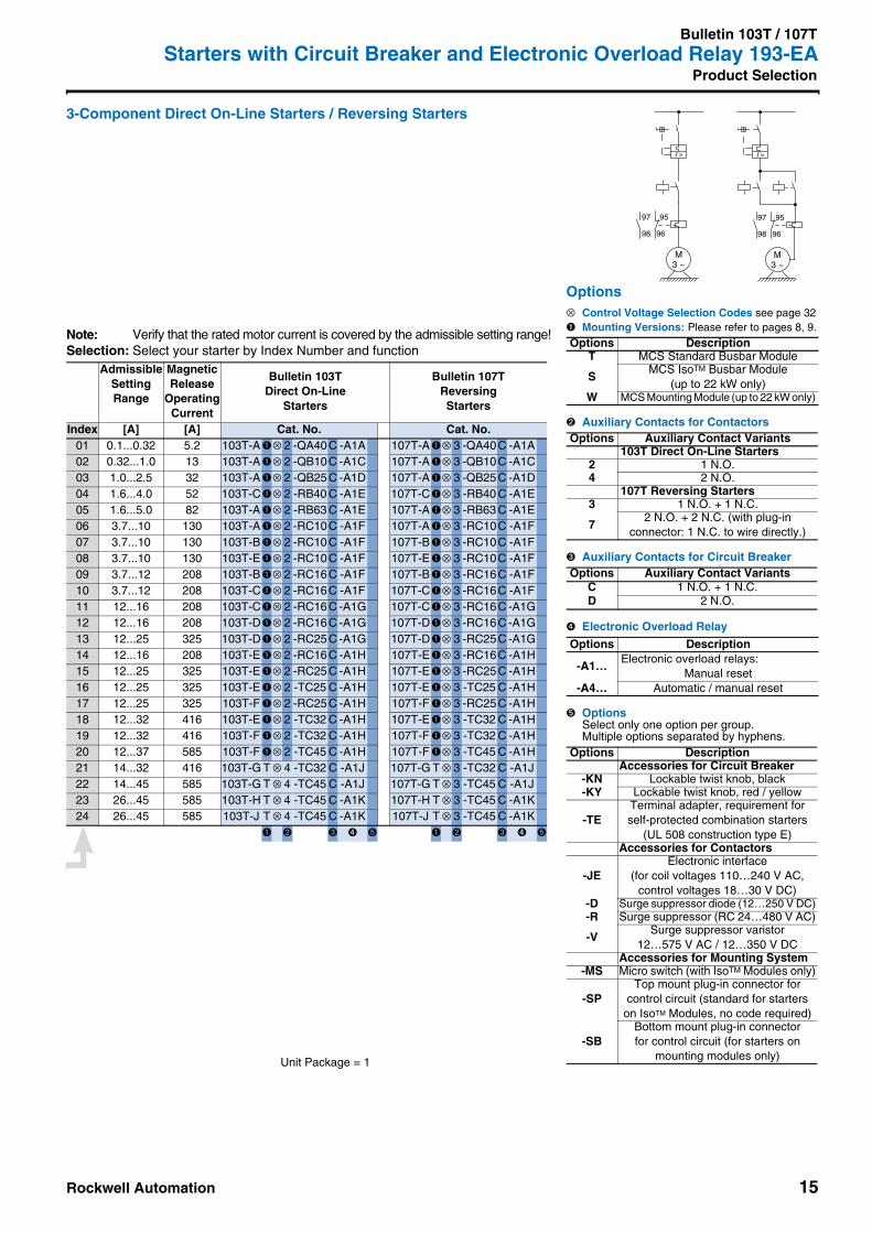
3-Component Direct On-Line Starters / Reversing Starters
Note: Verify that the rated motor current is covered by the admissible setting range!Selection: Select your starter by Index Number and function
AdmissibleSettingRange
MagneticRelease
OperatingCurrent
Bulletin 103TDirect On-Line
Starters
Bulletin 107TReversingStarters
Index [A] [A] Cat. No. Cat. No.01 0.1...0.32 5.2 103T-A ➊⊗ 2 -QA40C -A1A 107T-A ➊⊗ 3 -QA40C -A1A02 0.32...1.0 13 103T-A ➊⊗ 2 -QB10C -A1C 107T-A ➊⊗ 3 -QB10C -A1C03 1.0...2.5 32 103T-A ➊⊗ 2 -QB25C -A1D 107T-A ➊⊗ 3 -QB25C -A1D04 1.6...4.0 52 103T-C➊⊗ 2 -RB40 C -A1E 107T-C➊⊗ 3 -RB40 C -A1E05 1.6...5.0 82 103T-A ➊⊗ 2 -RB63 C -A1E 107T-A ➊⊗ 3 -RB63 C -A1E06 3.7...10 130 103T-A ➊⊗ 2 -RC10C -A1F 107T-A ➊⊗ 3 -RC10C -A1F07 3.7...10 130 103T-B ➊⊗ 2 -RC10C -A1F 107T-B ➊⊗ 3 -RC10C -A1F08 3.7...10 130 103T-E ➊⊗ 2 -RC10C -A1F 107T-E ➊⊗ 3 -RC10C -A1F09 3.7...12 208 103T-B ➊⊗ 2 -RC16C -A1F 107T-B ➊⊗ 3 -RC16C -A1F10 3.7...12 208 103T-C➊⊗ 2 -RC16C -A1F 107T-C➊⊗ 3 -RC16C -A1F11 12...16 208 103T-C➊⊗ 2 -RC16C -A1G 107T-C➊⊗ 3 -RC16C -A1G12 12...16 208 103T-D➊⊗ 2 -RC16C -A1G 107T-D➊⊗ 3 -RC16C -A1G13 12...25 325 103T-D➊⊗ 2 -RC25C -A1G 107T-D➊⊗ 3 -RC25C -A1G14 12...16 208 103T-E ➊⊗ 2 -RC16C -A1H 107T-E ➊⊗ 3 -RC16C -A1H15 12...25 325 103T-E ➊⊗ 2 -RC25C -A1H 107T-E ➊⊗ 3 -RC25C -A1H16 12...25 325 103T-E ➊⊗ 2 -TC25 C -A1H 107T-E ➊⊗ 3 -TC25 C -A1H17 12...25 325 103T-F ➊⊗ 2 -RC25C -A1H 107T-F ➊⊗ 3 -RC25C -A1H18 12...32 416 103T-E ➊⊗ 2 -TC32 C -A1H 107T-E ➊⊗ 3 -TC32 C -A1H19 12...32 416 103T-F ➊⊗ 2 -TC32 C -A1H 107T-F ➊⊗ 3 -TC32 C -A1H20 12...37 585 103T-F ➊⊗ 2 -TC45 C -A1H 107T-F ➊⊗ 3 -TC45 C -A1H21 14...32 416 103T-G T ⊗ 4 -TC32 C -A1J 107T-G T ⊗ 3 -TC32 C -A1J22 14...45 585 103T-G T ⊗ 4 -TC45 C -A1J 107T-G T ⊗ 3 -TC45 C -A1J23 26...45 585 103T-H T ⊗ 4 -TC45 C -A1K 107T-H T ⊗ 3 -TC45 C -A1K24 26...45 585 103T-J T ⊗ 4 -TC45 C -A1K 107T-J T ⊗ 3 -TC45 C -A1K
➊ ➋ ➌ ➍ ➎ ➊ ➋ ➌ ➍ ➎
M3 ~
I >
97 95
98 96
M3 ~
I >
97 95
98 96
Options⊗ Control Voltage Selection Codes see page 32➊ Mounting Versions: Please refer to pages 8, 9.
➋ Auxiliary Contacts for Contactors
➌ Auxiliary Contacts for Circuit Breaker
➍ Electronic Overload Relay
➎ OptionsSelect only one option per group.Multiple options separated by hyphens.
Options DescriptionT MCS Standard Busbar Module
SMCS IsoTM Busbar Module
(up to 22 kW only)W MCS Mounting Module (up to 22 kW only)
Options Auxiliary Contact Variants103T Direct On-Line Starters
2 1 N.O.4 2 N.O.
107T Reversing Starters3 1 N.O. + 1 N.C.
72 N.O. + 2 N.C. (with plug-in
connector: 1 N.C. to wire directly.)
Options Auxiliary Contact VariantsC 1 N.O. + 1 N.C.D 2 N.O.
Options Description
-A1…Electronic overload relays:
Manual reset-A4… Automatic / manual reset
Options DescriptionAccessories for Circuit Breaker
-KN Lockable twist knob, black-KY Lockable twist knob, red / yellow
-TETerminal adapter, requirement forself-protected combination starters
(UL 508 construction type E)Accessories for Contactors
-JEElectronic interface
(for coil voltages 110…240 V AC, control voltages 18…30 V DC)
-D Surge suppressor diode (12…250 V DC)-R Surge suppressor (RC 24…480 V AC)
-VSurge suppressor varistor
12…575 V AC / 12…350 V DCAccessories for Mounting System
-MS Micro switch (with IsoTM Modules only)
-SPTop mount plug-in connector for
control circuit (standard for starterson IsoTM Modules, no code required)
-SBBottom mount plug-in connectorfor control circuit (for starters on
mounting modules only)Unit Package = 1
16 Rockwell Automation
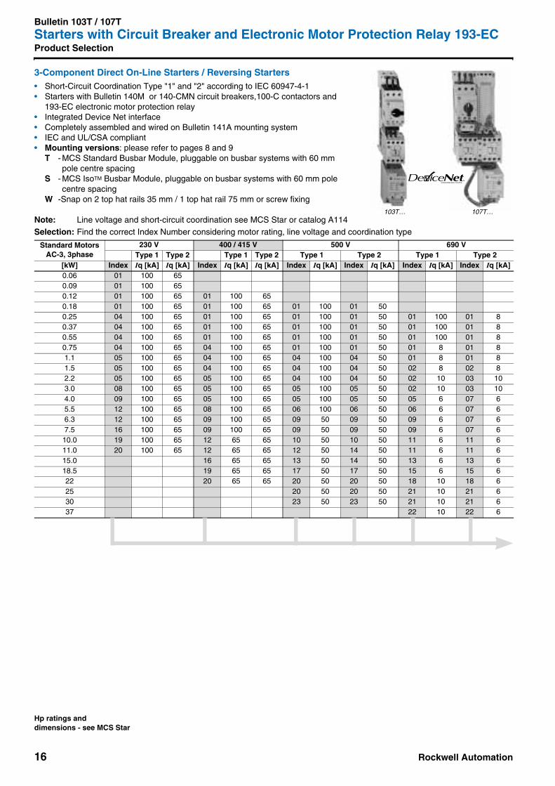
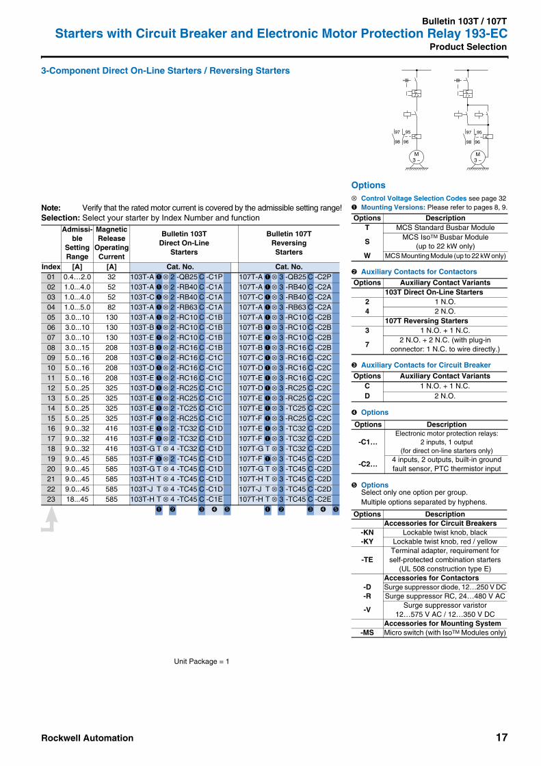
Bulletin 103T / 107TStarters with Circuit Breaker and Electronic Motor Protection Relay 193-ECProduct Selection
3-Component Direct On-Line Starters / Reversing Starters • Short-Circuit Coordination Type "1" and "2" according to IEC 60947-4-1• Starters with Bulletin 140M or 140-CMN circuit breakers,100-C contactors and
193-EC electronic motor protection relay• Integrated Device Net interface• Completely assembled and wired on Bulletin 141A mounting system• IEC and UL/CSA compliant• Mounting versions: please refer to pages 8 and 9
T - MCS Standard Busbar Module, pluggable on busbar systems with 60 mmpole centre spacing
S - MCS IsoTM Busbar Module, pluggable on busbar systems with 60 mm polecentre spacing
W -Snap on 2 top hat rails 35 mm / 1 top hat rail 75 mm or screw fixing
Note: Line voltage and short-circuit coordination see MCS Star or catalog A114Selection: Find the correct Index Number considering motor rating, line voltage and coordination type
Standard MotorsAC-3, 3phase
230 V 400 / 415 V 500 V 690 VType 1 Type 2 Type 1 Type 2 Type 1 Type 2 Type 1 Type 2
[kW] Index Iq [kA] Iq [kA] Index Iq [kA] Iq [kA] Index Iq [kA] Index Iq [kA] Index Iq [kA] Index Iq [kA]0.06 01 100 650.09 01 100 650.12 01 100 65 01 100 650.18 01 100 65 01 100 65 01 100 01 500.25 04 100 65 01 100 65 01 100 01 50 01 100 01 80.37 04 100 65 01 100 65 01 100 01 50 01 100 01 80.55 04 100 65 01 100 65 01 100 01 50 01 100 01 80.75 04 100 65 04 100 65 01 100 01 50 01 8 01 81.1 05 100 65 04 100 65 04 100 04 50 01 8 01 81.5 05 100 65 04 100 65 04 100 04 50 02 8 02 82.2 05 100 65 05 100 65 04 100 04 50 02 10 03 103.0 08 100 65 05 100 65 05 100 05 50 02 10 03 104.0 09 100 65 05 100 65 05 100 05 50 05 6 07 65.5 12 100 65 08 100 65 06 100 06 50 06 6 07 66.3 12 100 65 09 100 65 09 50 09 50 09 6 07 67.5 16 100 65 09 100 65 09 50 09 50 09 6 07 6
10.0 19 100 65 12 65 65 10 50 10 50 11 6 11 611.0 20 100 65 12 65 65 12 50 14 50 11 6 11 615.0 16 65 65 13 50 14 50 13 6 13 618.5 19 65 65 17 50 17 50 15 6 15 622 20 65 65 20 50 20 50 18 10 18 625 20 50 20 50 21 10 21 630 23 50 23 50 21 10 21 637 22 10 22 6
CONFORMANCE TESTEDTM
103T… 107T…
Hp ratings anddimensions - see MCS Star
Rockwell Automation 17
Bulletin 103T / 107TStarters with Circuit Breaker and Electronic Motor Protection Relay 193-EC
Product Selection
3-Component Direct On-Line Starters / Reversing Starters
Note: Verify that the rated motor current is covered by the admissible setting range!Selection: Select your starter by Index Number and function
Admissi-ble
SettingRange
MagneticRelease
OperatingCurrent
Bulletin 103TDirect On-Line
Starters
Bulletin 107TReversingStarters
Index [A] [A] Cat. No. Cat. No.01 0.4…2.0 32 103T-A ➊ ⊗ 2 -QB25 C -C1P 107T-A ➊ ⊗ 3 -QB25 C -C2P02 1.0...4.0 52 103T-A ➊ ⊗ 2 -RB40 C -C1A 107T-A ➊ ⊗ 3 -RB40 C -C2A03 1.0...4.0 52 103T-C ➊ ⊗ 2 -RB40 C -C1A 107T-C ➊ ⊗ 3 -RB40 C -C2A04 1.0...5.0 82 103T-A ➊ ⊗ 2 -RB63 C -C1A 107T-A ➊ ⊗ 3 -RB63 C -C2A05 3.0...10 130 103T-A ➊ ⊗ 2 -RC10 C -C1B 107T-A ➊ ⊗ 3 -RC10 C -C2B06 3.0...10 130 103T-B ➊ ⊗ 2 -RC10 C -C1B 107T-B ➊ ⊗ 3 -RC10 C -C2B07 3.0...10 130 103T-E ➊ ⊗ 2 -RC10 C -C1B 107T-E ➊ ⊗ 3 -RC10 C -C2B08 3.0...15 208 103T-B ➊ ⊗ 2 -RC16 C -C1B 107T-B ➊ ⊗ 3 -RC16 C -C2B09 5.0...16 208 103T-C ➊ ⊗ 2 -RC16 C -C1C 107T-C ➊ ⊗ 3 -RC16 C -C2C10 5.0...16 208 103T-D ➊ ⊗ 2 -RC16 C -C1C 107T-D ➊ ⊗ 3 -RC16 C -C2C11 5.0...16 208 103T-E ➊ ⊗ 2 -RC16 C -C1C 107T-E ➊ ⊗ 3 -RC16 C -C2C12 5.0...25 325 103T-D ➊ ⊗ 2 -RC25 C -C1C 107T-D ➊ ⊗ 3 -RC25 C -C2C13 5.0...25 325 103T-E ➊ ⊗ 2 -RC25 C -C1C 107T-E ➊ ⊗ 3 -RC25 C -C2C14 5.0...25 325 103T-E ➊ ⊗ 2 -TC25 C -C1C 107T-E ➊ ⊗ 3 -TC25 C -C2C15 5.0...25 325 103T-F ➊ ⊗ 2 -RC25 C -C1C 107T-F ➊ ⊗ 3 -RC25 C -C2C16 9.0...32 416 103T-E ➊ ⊗ 2 -TC32 C -C1D 107T-E ➊ ⊗ 3 -TC32 C -C2D17 9.0...32 416 103T-F ➊ ⊗ 2 -TC32 C -C1D 107T-F ➊ ⊗ 3 -TC32 C -C2D18 9.0...32 416 103T-G T ⊗ 4 -TC32 C -C1D 107T-G T ⊗ 3 -TC32 C -C2D19 9.0...45 585 103T-F ➊ ⊗ 2 -TC45 C -C1D 107T-F ➊ ⊗ 3 -TC45 C -C2D20 9.0...45 585 103T-G T ⊗ 4 -TC45 C -C1D 107T-G T ⊗ 3 -TC45 C -C2D21 9.0...45 585 103T-H T ⊗ 4 -TC45 C -C1D 107T-H T ⊗ 3 -TC45 C -C2D22 9.0...45 585 103T-J T ⊗ 4 -TC45 C -C1D 107T-J T ⊗ 3 -TC45 C -C2D23 18...45 585 103T-H T ⊗ 4 -TC45 C -C1E 107T-H T ⊗ 3 -TC45 C -C2E
➊ ➋ ➌ ➍ ➎ ➊ ➋ ➌ ➍ ➎
M3 ~
I >
97 95
98 96
M3 ~
I >
97 95
98 96
Options⊗ Control Voltage Selection Codes see page 32➊ Mounting Versions: Please refer to pages 8, 9.
➋ Auxiliary Contacts for Contactors
➌ Auxiliary Contacts for Circuit Breaker
➍ Options
➎ OptionsSelect only one option per group.Multiple options separated by hyphens.
Options DescriptionT MCS Standard Busbar Module
SMCS IsoTM Busbar Module
(up to 22 kW only)W MCS Mounting Module (up to 22 kW only)
Options Auxiliary Contact Variants103T Direct On-Line Starters
2 1 N.O.4 2 N.O.
107T Reversing Starters3 1 N.O. + 1 N.C.
72 N.O. + 2 N.C. (with plug-in
connector: 1 N.C. to wire directly.)
Options Auxiliary Contact VariantsC 1 N.O. + 1 N.C.D 2 N.O.
Options Description
-C1…Electronic motor protection relays:
2 inputs, 1 output (for direct on-line starters only)
-C2…4 inputs, 2 outputs, built-in ground fault sensor, PTC thermistor input
Options DescriptionAccessories for Circuit Breakers
-KN Lockable twist knob, black-KY Lockable twist knob, red / yellow
-TETerminal adapter, requirement forself-protected combination starters
(UL 508 construction type E)Accessories for Contactors
-D Surge suppressor diode, 12…250 V DC-R Surge suppressor RC, 24…480 V AC
-VSurge suppressor varistor
12…575 V AC / 12…350 V DCAccessories for Mounting System
-MS Micro switch (with IsoTM Modules only)
Unit Package = 1

18 Rockwell Automation
Bulletin 190S / 191SCompact Starters with Circuit BreakerProduct Selection
Direct On-Line Starters / Reversing Starters • Short-Circuit Coordination Type "1" and "2" according to IEC 60947-4-1• Accessories: Bulletin 140M circuit breakers and 100-C contactors• Complete unit, ready for connection with internal wiring• All control connections at the bottom of the starter• Removable cover• IEC and UL/CSA compliant• Mounting versions: please refer to pages 8 and 9
-Snap on 2 (1) top hat rails 35 mm / 1 top hat rail 75 mm or screw fixing
Note: Line voltage and short-circuit coordination see MCS Star or catalog A114Selection: Find the correct Index Number considering motor rating, line voltage and coordination type Standard Motors
AC-3, 3phase230 V 400 / 415 V 500 V 690 V
Type 2 Type 2 Type 1 Type 2 Type 1 Type 2[kW] Index Iq [kA] Index Iq [kA] Index Iq [kA] Index Iq [kA] Index Iq [kA] Index Iq [kA]0.02 2 65 1 650.04 3 65 2 650.06 4 65 2 65 2 65 2 50 1 65 1 500.09 4 65 3 65 3 65 3 50 2 65 2 500.12 5 65 4 65 3 65 3 50 3 65 3 500.18 6 65 4 65 4 65 4 50 3 65 3 500.25 6 65 5 65 5 65 5 50 4 65 4 500.37 7 65 6 65 5 65 5 50 5 65 5 50
0.558 50 6 65 6 65 6 50 5 65 5 509 65
0.758 50 7 65 6 65 6 50 6 10 6 89 65
1.111 50 8 50 7 65 7 50 6 10 6 812 65 9 65
1.511 50 8 50 8 65 9 50 7 8 7 812 65 9 65
2.214 50 11 50 8 65 9 50 8 8 10 1016 65 12 65
3.020 50 14 50 11 65 12 50 8 8 10 1021 65 16 65
4.022 50 14 50 14 50 16 50 12 10 13 1023 65 16 65
5.526 65 20 50 15 50 17 50 17 6 19 6
21 65
6.329 65 22 50 23 50 23 50 18 6 19 6
23 657.5 34 65 22 50 23 50 23 50 18 6 19 69.0 35 65 26 65 24 50 24 50 24 6 25 6
10.0 37 65 29 65 26 50 28 50 24 6 25 611.0 38 65 29 65 26 50 28 50 25 6 25 613.0 38 65 34 65 29 50 32 50 25 6 25 615.0 34 65 30 50 32 50 27 6 27 617.0 37 65 35 50 35 50 31 6 31 618.5 37 65 35 50 35 50 31 6 31 620 38 65 35 50 36 50 33 10 33 622 38 65 38 50 38 50 36 10 36 625 38 50 38 50
190S… 191S…
Hp ratings anddimensions - see MCS Star

Rockwell Automation 19
Bulletin 190S / 191SCompact Starters with Circuit Breaker
Product Selection
Direct On-Line Starters / Reversing Starters
Note: Verify that the circuit breaker can be set to the rated motor current!Selection: Select your starter by Index Number and function
Motor CurrentSettingRange
MagneticRelease
OperatingCurrent
Bulletin 190SDirect On-Line
Starters
Bulletin 191SReversingStarters
Index [A] [A] Cat. No. Cat. No.1 0.1...0.16 2.1 190S-AN⊗ 2 -CA16 C 191S-AN⊗ 3 -CA16 C2 0.16...0.25 3.3 190S-AN⊗ 2 -CA25 C 191S-AN⊗ 3 -CA25 C3 0.25...0.4 5.2 190S-AN⊗ 2 -CA40 C 191S-AN⊗ 3 -CA40 C4 0.4...0.63 8.2 190S-AN⊗ 2 -CA63 C 191S-AN⊗ 3 -CA63 C5 0.63...1.0 13 190S-AN⊗ 2 -CB10 C 191S-AN⊗ 3 -CB10 C6 1.0...1.6 21 190S-AN⊗ 2 -CB16 C 191S-AN⊗ 3 -CB16 C7 1.6...2.5 33 190S-AN⊗ 2 -CB25 C 191S-AN⊗ 3 -CB25 C8 2.5...4.0 52 190S-AN⊗ 2 -CB40 C 191S-AN⊗ 3 -CB40 C9 2.5...4.0 52 190S-AN⊗ 2 -DB40 C 191S-AN⊗ 3 -DB40 C
10 2.5...4.0 52 190S-CN⊗ 2 -DB40 C 191S-CN⊗ 3 -DB40 C11 4.0...6.3 82 190S-AN⊗ 2 -CB63 C 191S-AN⊗ 3 -CB63 C12 4.0...6.3 82 190S-AN⊗ 2 -DB63 C 191S-AN⊗ 3 -DB63 C13 4.0...6.3 82 190S-EN⊗ 3 -DB63 C —14 6.3...10 130 190S-AN⊗ 2 -CC10 C 191S-AN⊗ 3 -CC10 C15 6.3...10 130 190S-BN⊗ 2 -CC10 C 191S-BN⊗ 3 -CC10 C16 6.3...10 130 190S-AN⊗ 2 -DC10 C 191S-AN⊗ 3 -DC10 C17 6.3...10 130 190S-BN⊗ 2 -DC10 C 191S-BN⊗ 3 -DC10 C18 6.3...10 130 190S-CN⊗ 2 -DC10 C 191S-CN⊗ 3 -DC10 C19 6.3...10 130 190S-EN⊗ 3 -DC10 C —20 10...16 208 190S-BN⊗ 2 -CC16 C 191S-BN⊗ 3 -CC16 C21 10...16 208 190S-BN⊗ 2 -DC16 C 191S-BN⊗ 3 -DC16 C22 10...16 208 190S-CN⊗ 2 -CC16 C 191S-CN⊗ 3 -CC16 C23 10...16 208 190S-CN⊗ 2 -DC16 C 191S-CN⊗ 3 -DC16 C24 10...16 208 190S-DN⊗ 2 -DC16 C 191S-DN⊗ 3 -DC16 C25 10...16 208 190S-EN⊗ 3 -DC16 C —26 14.5...20 260 190S-DN⊗ 2 -DC20 C 191S-DN⊗ 3 -DC20 C27 14.5...20 260 190S-EN⊗ 3 -DC20 C —28 14.5...20 260 190S-EN⊗ 3 -FC20 C —29 18...25 325 190S-DN⊗ 2 -DC25 C 191S-DN⊗ 3 -DC25 C30 18...25 325 190S-EN⊗ 3 -DC25 C —31 18...25 325 190S-FN⊗ 3 -DC25 C —32 18...25 325 190S-EN⊗ 3 -FC25 C —33 18...25 325 190S-GN⊗ 3 -FC25 C —34 25...32 416 190S-EN⊗ 3 -FC32 C —35 25...32 416 190S-FN⊗ 3 -FC32 C —36 25...32 416 190S-GN⊗ 3 -FC32 C —37 32...45 585 190S-FN⊗ 3 -FC45 C —38 32...45 585 190S-GN⊗ 3 -FC45 C —
➊ ➋ ➌ ➊ ➋ ➌
Options⊗ Control Voltage Selection Codes
see page 32➊ Auxiliary Contacts for Contactors
➋ Auxiliary Contacts + Trip Contactsfor Circuit Breakers(Front mounting)
➌ OptionsSelect only one option per group.Multiple options separated by hyphens.
Bulletin 191S Reversing Starters:Mechanical interlock includedReversing starters can only be deliveredwith AC-control (Electronic interfaces can be used alternatively)
Type Option Auxiliary Contact Variants
190S-A…D1 1 N.C.2 1 N.O.
190S-E…G 3 1 N.O. + 1 N.C.
191S-A…D1 N.C. is used for electric interlock
3 1 N.O. + 1 N.C.
Option Auxiliary Contact VariantsC 1 N.O. + 1 N.C.D 2 N.O.S 1 N.O. + 1 N.O. trip contact
Options DescriptionAccessories for Circuit Breaker
-KN Lockable twist knob, black-KY Lockable twist knob, red / yellow
-TETerminal adapter, requirement forself-protected combination starters
(UL 508 construction type E)Accessories for Contactors
-JEElectronic interface
(for coil voltages 110…240 V AC, control voltages 18…30 V DC)
-DSurge suppressor diode
12…250 V DC
-RSurge suppressor RC
24…480 V AC
-VSurge suppressor varistor
12…575 V AC / 12…350 V DCControl Plug
-SP Plug-in connector for control circuit
M3 ~
I >
M3 ~
I >
Unit Package = 1
20 Rockwell Automation
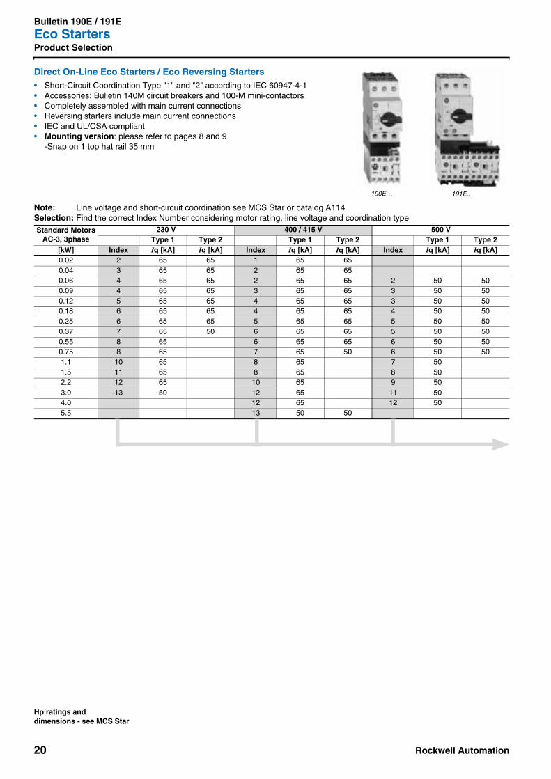
Bulletin 190E / 191EEco StartersProduct Selection
Direct On-Line Eco Starters / Eco Reversing Starters • Short-Circuit Coordination Type "1" and "2" according to IEC 60947-4-1• Accessories: Bulletin 140M circuit breakers and 100-M mini-contactors• Completely assembled with main current connections• Reversing starters include main current connections• IEC and UL/CSA compliant• Mounting version: please refer to pages 8 and 9
-Snap on 1 top hat rail 35 mm
Note: Line voltage and short-circuit coordination see MCS Star or catalog A114Selection: Find the correct Index Number considering motor rating, line voltage and coordination type Standard Motors
AC-3, 3phase230 V 400 / 415 V 500 V
Type 1 Type 2 Type 1 Type 2 Type 1 Type 2[kW] Index Iq [kA] Iq [kA] Index Iq [kA] Iq [kA] Index Iq [kA] Iq [kA]0.02 2 65 65 1 65 650.04 3 65 65 2 65 650.06 4 65 65 2 65 65 2 50 500.09 4 65 65 3 65 65 3 50 500.12 5 65 65 4 65 65 3 50 500.18 6 65 65 4 65 65 4 50 500.25 6 65 65 5 65 65 5 50 500.37 7 65 50 6 65 65 5 50 500.55 8 65 6 65 65 6 50 500.75 8 65 7 65 50 6 50 501.1 10 65 8 65 7 501.5 11 65 8 65 8 502.2 12 65 10 65 9 503.0 13 50 12 65 11 504.0 12 65 12 505.5 13 50 50
190E… 191E…
Hp ratings anddimensions - see MCS Star

Rockwell Automation 21
Bulletin 190E / 191EEco Starters
Product Selection
Direct On-Line Eco Starters / Eco Reversing Starters
Note: Verify that the circuit breaker can be set to the rated motor current!Selection: Select your starter by Index Number and function
MotorCurrentSettingRange
MagneticRelease
OperatingCurrent
Bulletin 190EDirect On-Line
Starters
Bulletin 191EReversingStarters
Index [A] [A] Cat. No. Cat. No.1 0.1...0.16 2.1 190E-MN⊗ 2 -CA16 B 191E-MN⊗ 1 -CA16 B2 0.16...0.25 3.3 190E-MN⊗ 2 -CA25 B 191E-MN⊗ 1 -CA25 B3 0.25...0.4 5.2 190E-MN⊗ 2 -CA40 B 191E-MN⊗ 1 -CA40 B4 0.4...0.63 8.2 190E-MN⊗ 2 -CA63 B 191E-MN⊗ 1 -CA63 B5 0.63...1.0 13 190E-MN⊗ 2 -CB10 B 191E-MN⊗ 1 -CB10 B6 1.0...1.6 21 190E-MN⊗ 2 -CB16 B 191E-MN⊗ 1 -CB16 B7 1.6...2.5 33 190E-MN⊗ 2 -CB25 B 191E-MN⊗ 1 -CB25 B8 2.5...4.0 52 190E-MN⊗ 2 -CB40 B 191E-MN⊗ 1 -CB40 B9 2.5...4.0 52 190E-NN⊗ 2 -CB40 B 191E-NN⊗ 1 -CB40 B
10 4.0...6.3 82 190E-MN⊗ 2 -CB63 B 191E-MN⊗ 1 -CB63 B11 4.0...6.3 82 190E-NN⊗ 2 -CB63 B 191E-NN⊗ 1 -CB63 B12 6.3...10 130 190E-NN⊗ 2 -CC10 B 191E-NN⊗ 1 -CC10 B13 10...12 208 190E-PN⊗ 2 -CC16 B 191E-PN⊗ 1 -CC16 B
➊ ➋ ➊ ➋
Options⊗ Control Voltage Selection Codes
see page 32➊ Auxiliary Contacts for Contactors
191E Reversing Starters:Starters with AC-control with mechanical interlockStarters with DC-control only without mechanical interlock
➋ Auxiliary Contacts + Trip contacts for Circuit Breakers(Front mounting)
Type Option Auxiliary Contact Variants
190E1 1 N.C.2 1 N.O.
191E
1 N.C. is used for electric interlock1 1 N.C.5 1 N.O. + 2 N.C.6 2 N.O. + 1 N.C.
Option Auxiliary Contact VariantsA 1 N.C.B 1 N.O.C 1 N.O. + 1 N.C.D 2 N.O.S 1 N.O. + 1 N.O. trip contact
M3 ~
I >
M3 ~
I >
Unit Package = 1
22 Rockwell Automation
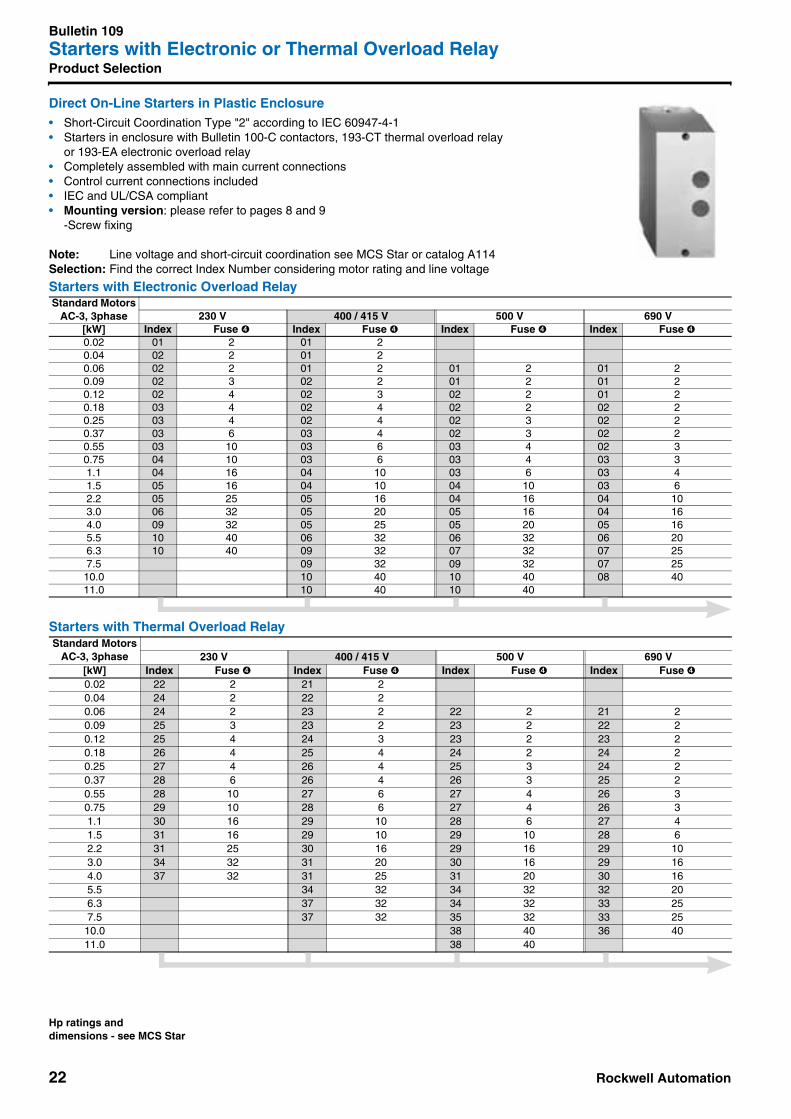
Bulletin 109Starters with Electronic or Thermal Overload RelayProduct Selection
Direct On-Line Starters in Plastic Enclosure • Short-Circuit Coordination Type "2" according to IEC 60947-4-1• Starters in enclosure with Bulletin 100-C contactors, 193-CT thermal overload relay
or 193-EA electronic overload relay• Completely assembled with main current connections• Control current connections included• IEC and UL/CSA compliant• Mounting version: please refer to pages 8 and 9
-Screw fixing
Note: Line voltage and short-circuit coordination see MCS Star or catalog A114Selection: Find the correct Index Number considering motor rating and line voltage
Starters with Electronic Overload Relay
Starters with Thermal Overload Relay
Standard MotorsAC-3, 3phase 230 V 400 / 415 V 500 V 690 V
[kW] Index Fuse ➍ Index Fuse ➍ Index Fuse ➍ Index Fuse ➍0.02 01 2 01 20.04 02 2 01 20.06 02 2 01 2 01 2 01 20.09 02 3 02 2 01 2 01 20.12 02 4 02 3 02 2 01 20.18 03 4 02 4 02 2 02 20.25 03 4 02 4 02 3 02 20.37 03 6 03 4 02 3 02 20.55 03 10 03 6 03 4 02 30.75 04 10 03 6 03 4 03 31.1 04 16 04 10 03 6 03 41.5 05 16 04 10 04 10 03 62.2 05 25 05 16 04 16 04 103.0 06 32 05 20 05 16 04 164.0 09 32 05 25 05 20 05 165.5 10 40 06 32 06 32 06 206.3 10 40 09 32 07 32 07 257.5 09 32 09 32 07 25
10.0 10 40 10 40 08 4011.0 10 40 10 40
Standard MotorsAC-3, 3phase 230 V 400 / 415 V 500 V 690 V
[kW] Index Fuse ➍ Index Fuse ➍ Index Fuse ➍ Index Fuse ➍0.02 22 2 21 20.04 24 2 22 20.06 24 2 23 2 22 2 21 20.09 25 3 23 2 23 2 22 20.12 25 4 24 3 23 2 23 20.18 26 4 25 4 24 2 24 20.25 27 4 26 4 25 3 24 20.37 28 6 26 4 26 3 25 20.55 28 10 27 6 27 4 26 30.75 29 10 28 6 27 4 26 31.1 30 16 29 10 28 6 27 41.5 31 16 29 10 29 10 28 62.2 31 25 30 16 29 16 29 103.0 34 32 31 20 30 16 29 164.0 37 32 31 25 31 20 30 165.5 34 32 34 32 32 206.3 37 32 34 32 33 257.5 37 32 35 32 33 25
10.0 38 40 36 4011.0 38 40
Hp ratings anddimensions - see MCS Star
Rockwell Automation 23
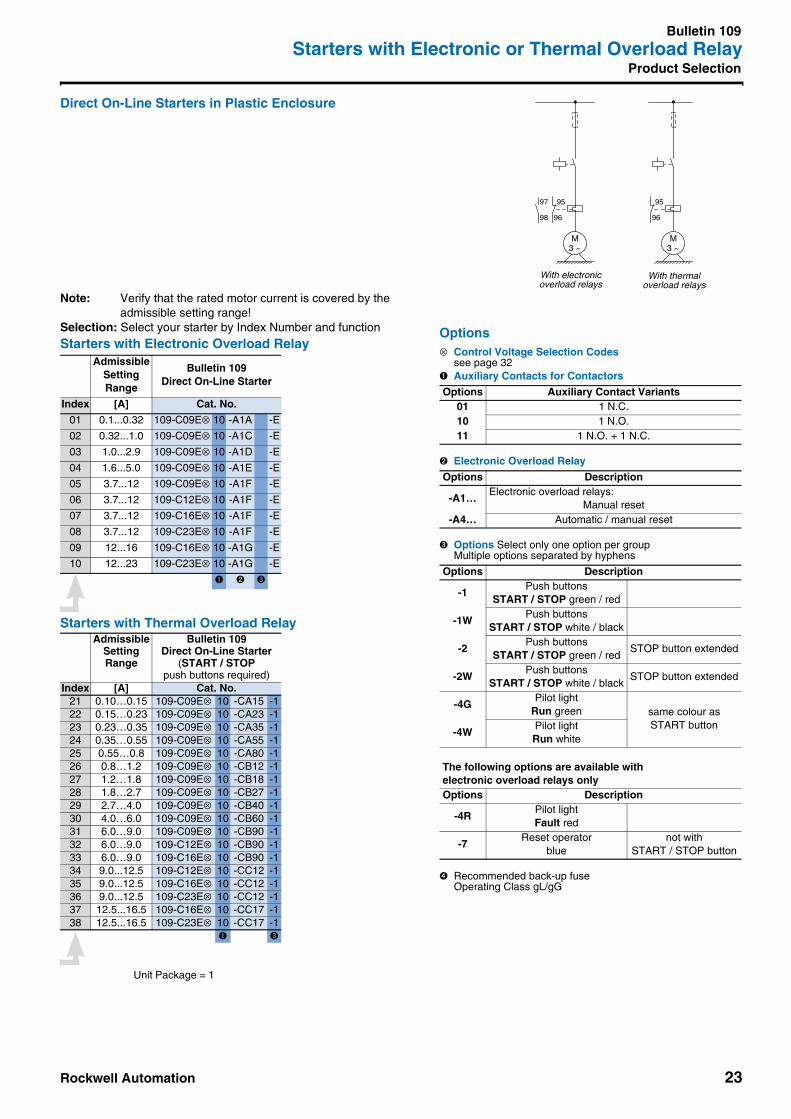
Bulletin 109Starters with Electronic or Thermal Overload Relay
Product Selection
Direct On-Line Starters in Plastic Enclosure
Note: Verify that the rated motor current is covered by the admissible setting range!
Selection: Select your starter by Index Number and functionStarters with Electronic Overload Relay
Starters with Thermal Overload Relay
AdmissibleSettingRange
Bulletin 109Direct On-Line Starter
Index [A] Cat. No.
01 0.1...0.32 109-C09E⊗ 10 -A1A -E
02 0.32...1.0 109-C09E⊗ 10 -A1C -E
03 1.0...2.9 109-C09E⊗ 10 -A1D -E
04 1.6...5.0 109-C09E⊗ 10 -A1E -E
05 3.7...12 109-C09E⊗ 10 -A1F -E
06 3.7...12 109-C12E⊗ 10 -A1F -E
07 3.7...12 109-C16E⊗ 10 -A1F -E
08 3.7...12 109-C23E⊗ 10 -A1F -E
09 12...16 109-C16E⊗ 10 -A1G -E
10 12...23 109-C23E⊗ 10 -A1G -E
➊ ➋ ➌
AdmissibleSettingRange
Bulletin 109Direct On-Line Starter
(START / STOPpush buttons required)
Index [A] Cat. No.21 0.10…0.15 109-C09E⊗ 10 -CA15 -122 0.15…0.23 109-C09E⊗ 10 -CA23 -123 0.23…0.35 109-C09E⊗ 10 -CA35 -124 0.35…0.55 109-C09E⊗ 10 -CA55 -125 0.55…0.8 109-C09E⊗ 10 -CA80 -126 0.8…1.2 109-C09E⊗ 10 -CB12 -127 1.2…1.8 109-C09E⊗ 10 -CB18 -128 1.8…2.7 109-C09E⊗ 10 -CB27 -129 2.7…4.0 109-C09E⊗ 10 -CB40 -130 4.0…6.0 109-C09E⊗ 10 -CB60 -131 6.0…9.0 109-C09E⊗ 10 -CB90 -132 6.0…9.0 109-C12E⊗ 10 -CB90 -133 6.0…9.0 109-C16E⊗ 10 -CB90 -134 9.0...12.5 109-C12E⊗ 10 -CC12 -135 9.0...12.5 109-C16E⊗ 10 -CC12 -136 9.0...12.5 109-C23E⊗ 10 -CC12 -137 12.5...16.5 109-C16E⊗ 10 -CC17 -138 12.5...16.5 109-C23E⊗ 10 -CC17 -1
➊ ➌
M3 ~
95
96
Options⊗ Control Voltage Selection Codes
see page 32➊ Auxiliary Contacts for Contactors
➋ Electronic Overload Relay
➌ Options Select only one option per groupMultiple options separated by hyphens
➍ Recommended back-up fuse Operating Class gL/gG
Options Auxiliary Contact Variants01 1 N.C.10 1 N.O.11 1 N.O. + 1 N.C.
Options Description
-A1…Electronic overload relays:
Manual reset-A4… Automatic / manual reset
Options Description
-1Push buttons
START / STOP green / red
-1WPush buttons
START / STOP white / black
-2Push buttons
START / STOP green / redSTOP button extended
-2WPush buttons
START / STOP white / blackSTOP button extended
-4GPilot light
Run green same colour asSTART button
-4WPilot lightRun white
The following options are available withelectronic overload relays onlyOptions Description
-4RPilot lightFault red
-7Reset operator
bluenot with
START / STOP button
M3 ~
97 95
98 96
With electronicoverload relays
With thermaloverload relays
Unit Package = 1

24 Rockwell Automation
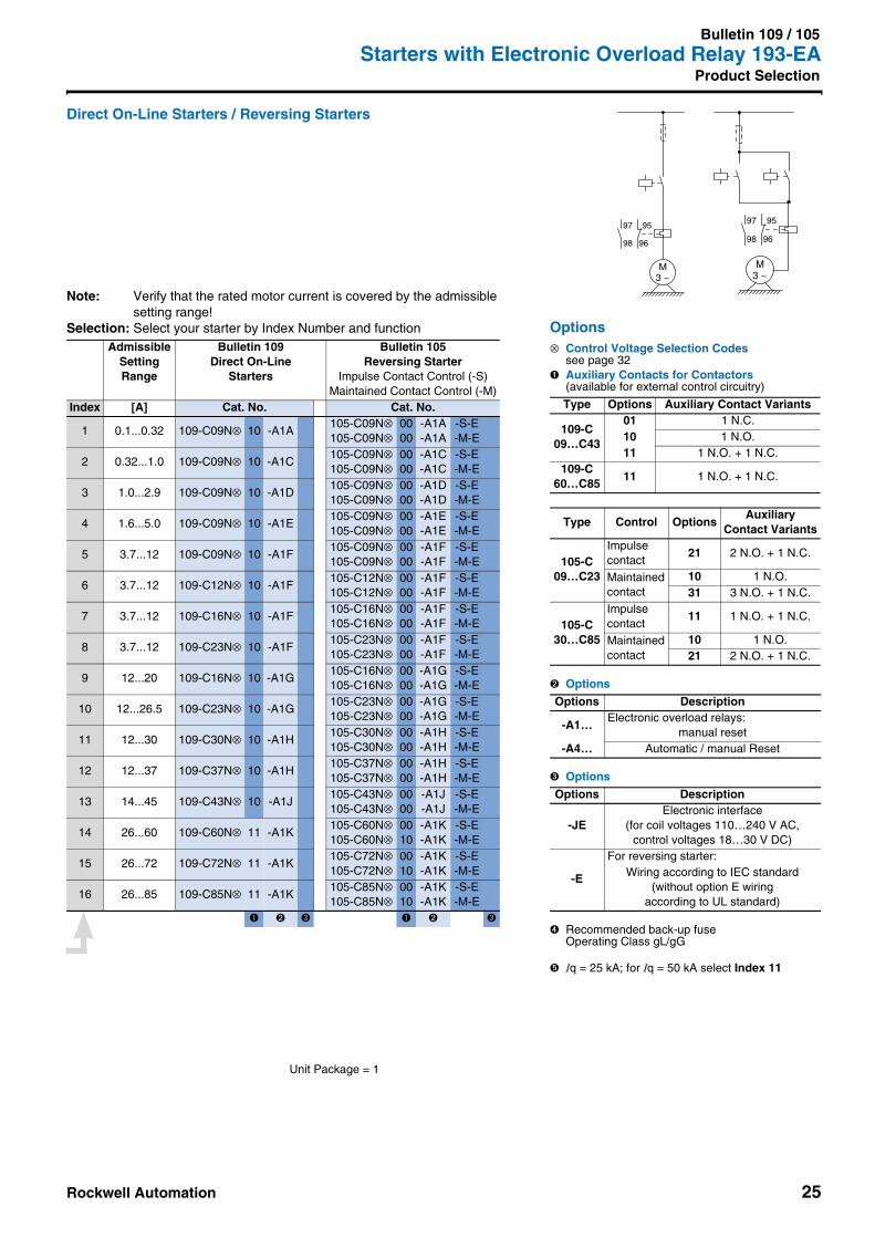
Bulletin 109 / 105Starters with Electronic Overload Relay 193-EAProduct Selection
Direct On-Line Starters / Reversing Starters• Short-Circuit Coordination Type "2" according to IEC 60947-4-1• Starters with Bulletin 100-C contactors and 193-EA electronic overload relay• Completely assembled with main current connections• Control current connections included• IEC and UL/CSA compliant• Mounting versions: please refer to pages 8 and 9
-Snap on 1 top hat rail 35 mm or screw fixing
Note: Line voltage and short-circuit coordination see MCS Star or catalog A114Selection: Find the correct Index Number considering motor rating and line voltage
Standard MotorsAC-3, 3phase
230 V 400 / 415 V 500 V 690 V
Fuse➍
Circuit Breaker(to order separately)
Iq = 65 kA
Fuse➍
Circuit Breaker(to order separately)
Iq = 65 kA
Fuse➍
Circuit Breaker(to order separately)
Iq = 50 kA
Fuse➍
[kW] Index [A] Cat. No. Index [A] Cat. No. Index [A] Cat. No. Index [A]0.02 1 2 140M-C2N-A25 1 2 140M-C2N-A250.04 2 2 140M-C2N-A40 1 2 140M-C2N-A400.06 2 2 140M-C2N-A63 1 2 140M-C2N-A40 1 2 140M-C2N-A25 1 20.09 2 3 140M-C2N-A63 2 2 140M-C2N-A40 1 2 140M-C2N-A40 1 20.12 2 4 140M-C2N-B16 2 3 140M-C2N-A63 2 2 140M-C2N-A40 1 20.18 3 4 140M-C2N-B16 2 4 140M-C2N-A63 2 2 140M-C2N-A63 2 20.25 3 4 140M-C2N-B16 2 4 140M-C2N-B10 2 3 140M-C2N-A63 2 20.37 3 6 140M-C2N-B25 3 4 140M-C2N-B16 2 3 140M-C2N-B10 2 20.55 3 10 140M-C2N-B25 3 6 140M-C2N-B16 3 4 140M-C2N-B16 2 30.75 4 10 140M-D8N-B40 3 6 140M-C2N-B25 3 4 140M-C2N-B16 3 31.1 4 16 140M-D8N-B63 4 10 140M-D8N-B40 3 6 140M-C2N-B25 3 41.5 5 16 140M-D8N-B63 5 10 140M-D8N-B40 4 10 140M-C2N-B25 3 62.2 5 25 140M-D8N-C10 5 16 140M-D8N-B63 4 16 140M-D8N-B63 4 103.0 6 32 140M-D8N-C16 5 20 140M-D8N-C10 5 16 140M-D8N-B63 4 164.0 9 32 140M-D8N-C16 5 25 140M-D8N-C10 5 20 140M-D8N-C10 5 165.5 10 40 140M-D8N-C25 6 32 140M-D8N-C16 6 32 140M-D8N-C10 6 206.3 10 40 140M-D8N-C25 9 32 140M-D8N-C16 7 32 140M-D8N-C16 7 257.5 11 63 140M-F8N-C32 9 32 140M-D8N-C16 9 32 140M-D8N-C16 7 25
10.0 12 80 140M-F8N-C45 10 40 140M-D8N-C25 10 40 140M-D8N-C16 8 4011.0 13 100 140M-F8N-C45 10 40 140M-D8N-C25 10 40 140M-D8N-C25 ➎ 11 4015.0 14 125 — 11 63 140M-F8N-C32 11 63 140M-F8N-C25 11 5018.5 14 160 — 12 80 140M-F8N-C45 12 80 140M-F8N-C32 12 5022 15 160 — 13 100 140M-F8N-C45 13 100 140M-F8N-C45 13 6325 16 160 — 14 125 — 13 100 140M-F8N-C45 14 8030 14 125 — 14 125 140M-F8N-C45 14 8037 15 160 — 14 125 — 15 10045 16 160 — 15 160 — 16 10055 16 160 —
109… 105…
Hp ratings anddimensions - see MCS Star
Rockwell Automation 25
Bulletin 109 / 105Starters with Electronic Overload Relay 193-EA
Product Selection
Direct On-Line Starters / Reversing Starters
Note: Verify that the rated motor current is covered by the admissible setting range!
Selection: Select your starter by Index Number and functionAdmissible
SettingRange
Bulletin 109Direct On-Line
Starters
Bulletin 105Reversing Starter
Impulse Contact Control (-S)Maintained Contact Control (-M)
Index [A] Cat. No. Cat. No.
1 0.1...0.32 109-C09N⊗ 10 -A1A105-C09N⊗105-C09N⊗
0000
-A1A-A1A
-S-E-M-E
2 0.32...1.0 109-C09N⊗ 10 -A1C105-C09N⊗105-C09N⊗
0000
-A1C-A1C
-S-E-M-E
3 1.0...2.9 109-C09N⊗ 10 -A1D105-C09N⊗105-C09N⊗
0000
-A1D-A1D
-S-E-M-E
4 1.6...5.0 109-C09N⊗ 10 -A1E105-C09N⊗105-C09N⊗
0000
-A1E-A1E
-S-E-M-E
5 3.7...12 109-C09N⊗ 10 -A1F105-C09N⊗105-C09N⊗
0000
-A1F-A1F
-S-E-M-E
6 3.7...12 109-C12N⊗ 10 -A1F105-C12N⊗105-C12N⊗
0000
-A1F-A1F
-S-E-M-E
7 3.7...12 109-C16N⊗ 10 -A1F105-C16N⊗105-C16N⊗
0000
-A1F-A1F
-S-E-M-E
8 3.7...12 109-C23N⊗ 10 -A1F105-C23N⊗105-C23N⊗
0000
-A1F-A1F
-S-E-M-E
9 12...20 109-C16N⊗ 10 -A1G105-C16N⊗105-C16N⊗
0000
-A1G-A1G
-S-E-M-E
10 12...26.5 109-C23N⊗ 10 -A1G105-C23N⊗105-C23N⊗
0000
-A1G-A1G
-S-E-M-E
11 12...30 109-C30N⊗ 10 -A1H105-C30N⊗105-C30N⊗
0000
-A1H-A1H
-S-E-M-E
12 12...37 109-C37N⊗ 10 -A1H105-C37N⊗105-C37N⊗
0000
-A1H-A1H
-S-E-M-E
13 14...45 109-C43N⊗ 10 -A1J105-C43N⊗105-C43N⊗
0000
-A1J-A1J
-S-E-M-E
14 26...60 109-C60N⊗ 11 -A1K105-C60N⊗105-C60N⊗
0010
-A1K-A1K
-S-E-M-E
15 26...72 109-C72N⊗ 11 -A1K105-C72N⊗105-C72N⊗
0010
-A1K-A1K
-S-E-M-E
16 26...85 109-C85N⊗ 11 -A1K105-C85N⊗105-C85N⊗
0010
-A1K-A1K
-S-E-M-E
➊ ➋ ➌ ➊ ➋ ➌
Options⊗ Control Voltage Selection Codes
see page 32➊ Auxiliary Contacts for Contactors
(available for external control circuitry)
➋ Options
➌ Options
➍ Recommended back-up fuseOperating Class gL/gG
➎ Iq = 25 kA; for Iq = 50 kA select Index 11
Type Options Auxiliary Contact Variants
109-C09…C43
01 1 N.C.10 1 N.O.11 1 N.O. + 1 N.C.
109-C60…C85
11 1 N.O. + 1 N.C.
Type Control OptionsAuxiliary
Contact Variants
105-C09…C23
Impulsecontact
21 2 N.O. + 1 N.C.
Maintainedcontact
10 1 N.O.31 3 N.O. + 1 N.C.
105-C30…C85
Impulsecontact
11 1 N.O. + 1 N.C.
Maintainedcontact
10 1 N.O.21 2 N.O. + 1 N.C.
Options Description
-A1…Electronic overload relays:
manual reset-A4… Automatic / manual Reset
Options Description
-JEElectronic interface
(for coil voltages 110…240 V AC, control voltages 18…30 V DC)
-E
For reversing starter:Wiring according to IEC standard
(without option E wiringaccording to UL standard)
M3 ~
97 95
98 96
M3 ~
97 95
98 96
Unit Package = 1
26 Rockwell Automation
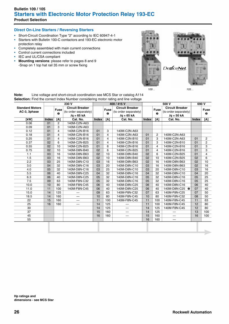
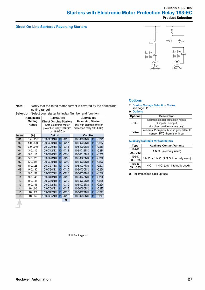
Bulletin 109 / 105Starters with Electronic Motor Protection Relay 193-ECProduct Selection
Direct On-Line Starters / Reversing Starters• Short-Circuit Coordination Type "2" according to IEC 60947-4-1• Starters with Bulletin 100-C contactors and 193-EC electronic motor
protection relay• Completely assembled with main current connections• Control current connections included• IEC and UL/CSA compliant• Mounting versions: please refer to pages 8 and 9
-Snap on 1 top hat rail 35 mm or screw fixing
Note: Line voltage and short-circuit coordination see MCS Star or catalog A114Selection: Find the correct Index Number considering motor rating and line voltage
Standard MotorsAC-3, 3phase
230 V 400 / 415 V 500 V 690 V
Fuse➋
Circuit Breaker(to order separately)
Iq = 65 kA
Fuse➋
Circuit Breaker(to order separately)
Iq = 65 kA
Fuse➋
Circuit Breaker(to order separately)
Iq = 50 kA
Fuse➋
[kW] Index [A] Cat. No. Index [A] Cat. No. Index [A] Cat. No. Index [A]0.06 01 2 140M-C2N-A630.09 01 3 140M-C2N-A630.12 01 4 140M-C2N-B16 01 3 140M-C2N-A630.18 01 4 140M-C2N-B16 01 4 140M-C2N-A63 01 2 140M-C2N-A630.25 01 4 140M-C2N-B16 01 4 140M-C2N-B10 01 3 140M-C2N-A63 01 20.37 02 6 140M-C2N-B25 01 4 140M-C2N-B16 01 3 140M-C2N-B10 01 20.55 02 10 140M-C2N-B25 01 6 140M-C2N-B16 01 4 140M-C2N-B16 01 30.75 02 10 140M-D8N-B40 02 6 140M-C2N-B25 01 4 140M-C2N-B16 01 31.1 03 16 140M-D8N-B63 02 10 140M-D8N-B40 02 6 140M-C2N-B25 01 41.5 03 16 140M-D8N-B63 02 10 140M-D8N-B40 02 10 140M-C2N-B25 02 62.2 03 25 140M-D8N-C10 03 16 140M-D8N-B63 02 16 140M-D8N-B63 02 103.0 04 32 140M-D8N-C16 03 20 140M-D8N-C10 03 16 140M-D8N-B63 02 164.0 05 32 140M-D8N-C16 03 25 140M-D8N-C10 03 20 140M-D8N-C10 03 165.5 06 40 140M-D8N-C25 04 32 140M-D8N-C16 04 32 140M-D8N-C10 04 206.3 06 40 140M-D8N-C25 05 32 140M-D8N-C16 05 32 140M-D8N-C16 05 257.5 09 63 140M-F8N-C32 05 32 140M-D8N-C16 05 32 140M-D8N-C16 05 25
10.0 10 80 140M-F8N-C45 06 40 140M-D8N-C25 06 40 140M-D8N-C16 06 4011.0 11 100 140M-F8N-C45 06 40 140M-D8N-C25 06 40 140M-D8N-C25 ➌ 07 4015.0 14 125 — 09 63 140M-F8N-C32 07 63 140M-F8N-C25 07 5018.5 14 160 — 10 80 140M-F8N-C45 10 80 140M-F8N-C32 08 5022 15 160 — 11 100 140M-F8N-C45 11 100 140M-F8N-C45 11 6325 16 160 — 14 125 — 11 100 140M-F8N-C45 12 8030 14 125 — 14 125 140M-F8N-C45 12 8037 15 160 — 14 125 — 13 10045 16 160 — 15 160 — 16 10055 16 160 —
109… 105…
CONFORMANCE TESTEDTM
Hp ratings anddimensions - see MCS Star
Rockwell Automation 27
Bulletin 109 / 105Starters with Electronic Motor Protection Relay 193-EC
Product Selection
Direct On-Line Starters / Reversing Starters
Note: Verify that the rated motor current is covered by the admissible setting range!
Selection: Select your starter by Index Number and functionAdmissible
Setting Range
Bulletin 109Direct On-Line Starters
(with electronic motor protection relay 193-EC1
or 193-EC2)
Bulletin 105Reversing Starter
(only with electronic motor protection relay 193-EC2)
Index [A] Cat. No. Cat. No.01 0.4…2.0 109-C09N⊗ 10 -C1P 105-C09N⊗ 11 -C2P02 1.0...5.0 109-C09N⊗ 10 -C1A 105-C09N⊗ 11 -C2A03 3.0...9.0 109-C09N⊗ 10 -C1B 105-C09N⊗ 11 -C2B04 3.0...12 109-C12N⊗ 10 -C1B 105-C12N⊗ 11 -C2B05 5.0...16 109-C16N⊗ 10 -C1C 105-C16N⊗ 11 -C2C06 5.0...23 109-C23N⊗ 10 -C1C 105-C23N⊗ 11 -C2C07 5.0...25 109-C30N⊗ 10 -C1C 105-C30N⊗ 11 -C2C08 5.0...25 109-C37N⊗ 10 -C1C 105-C37N⊗ 11 -C2C09 9.0...30 109-C30N⊗ 10 -C1D 105-C30N⊗ 11 -C2D10 9.0...37 109-C37N⊗ 10 -C1D 105-C37N⊗ 11 -C2D11 9.0...43 109-C43N⊗ 10 -C1D 105-C43N⊗ 11 -C2D12 9.0...45 109-C60N⊗ 11 -C1D 105-C60N⊗ 11 -C2D13 9.0...45 109-C72N⊗ 11 -C1D 105-C72N⊗ 11 -C2D14 18...60 109-C60N⊗ 11 -C1E 105-C60N⊗ 11 -C2E15 18...72 109-C72N⊗ 11 -C1E 105-C72N⊗ 11 -C2E16 18...85 109-C85N⊗ 11 -C1E 105-C85N⊗ 11 -C2E
➊
Options⊗ Control Voltage Selection Codes
see page 32➊ Options
Auxiliary Contacts for Contactors
➋ Recommended back-up fuse
Options Description
-C1…Electronic motor protection relays:
2 inputs, 1 output (for direct on-line starters only)
-C2…4 inputs, 2 outputs, built-in ground fault
sensor, PTC thermistor input
Type Auxiliary Contact Variants109-C
09…C431 N.O. (internally used)
109-C60…C85
1 N.O. + 1 N.C. (1 N.O. internally used)
105-C09…C85
1 N.O. + 1 N.C. (both internally used)
M3 ~
97 95
98 96
M3 ~
97 95
98 96
Unit Package = 1

28 Rockwell Automation
Bulletin 109 / 105Starters with Thermal Overload Relay 193-CTProduct Selection
Direct On-Line Starters / Reversing Starters• Short-Circuit Coordination Type "2" according to IEC 60947-4-1• Starters with Bulletin 100-C contactors and 193-CT thermal overload relay• Completely assembled with main current connections• Control current connections included• IEC and UL/CSA compliant• Mounting versions: please refer to pages 8 and 9
-Snap on 1 top hat rail 35 mm or screw fixing
Note: Line voltage and short-circuit coordination see MCS Star or catalog A114Selection: Find the correct Index Number considering motor rating and line voltage
Standard MotorsAC-3, 3phase
230 V 400 / 415 V 500 V 690 V
Fuse➌
Circuit Breaker(to order separately)
Iq = 65 kA
Fuse➌
Circuit Breaker(to order separately)
Iq = 65 kA
Fuse➌
Circuit Breaker(to order separately)
Iq = 50 kA
Fuse➌
[kW] Index [A] Cat. No. Index [A] Cat. No. Index [A] Cat. No. Index [A]
0.02 02 2 140M-C2N-A25 01 2 140M-C2N-A25
0.04 04 2 140M-C2N-A40 02 2 140M-C2N-A40
0.06 04 2 140M-C2N-A63 03 2 140M-C2N-A40 02 2 140M-C2N-A25 01 2
0.09 05 3 140M-C2N-A63 03 2 140M-C2N-A40 03 2 140M-C2N-A40 02 2
0.12 05 4 140M-C2N-B16 04 3 140M-C2N-A63 03 2 140M-C2N-A40 03 2
0.18 06 4 140M-C2N-B16 05 4 140M-C2N-A63 04 2 140M-C2N-A63 04 2
0.25 07 4 140M-C2N-B16 06 4 140M-C2N-B10 05 3 140M-C2N-A63 04 2
0.37 08 6 140M-C2N-B25 06 4 140M-C2N-B16 06 3 140M-C2N-B10 05 2
0.56 08 10 140M-C2N-B25 07 6 140M-C2N-B16 07 4 140M-C2N-B16 06 3
0.75 09 10 140M-D8N-B40 08 6 140M-C2N-B25 07 4 140M-C2N-B16 06 3
1.1 10 16 140M-D8N-B63 09 10 140M-D8N-B40 08 6 140M-C2N-B25 07 4
1.5 11 16 140M-D8N-B63 09 10 140M-D8N-B40 09 10 140M-C2N-B25 08 6
2.2 11 25 140M-D8N-C10 10 16 140M-D8N-B63 09 16 140M-D8N-B63 09 10
3.0 14 32 140M-D8N-C16 11 20 140M-D8N-C10 10 16 140M-D8N--B63 09 16
4.0 17 32 140M-D8N-C16 11 25 140M-D8N-C10 11 20 140M-D8N-C10 10 16
5.5 14 32 140M-D8N-C16 14 32 140M-D8N-C10 12 20
6.3 17 32 140M-D8N-C16 14 32 140M-D8N-C16 13 25
7.5 17 32 140M-D8N-C16 15 32 140M-D8N-C16 13 25
10.0 18 40 140M-D8N-C16 16 40
11.0 18 40 140M-D8N-C25 ➍
109… 105…
Hp ratings anddimensions - see MCS Star

Rockwell Automation 29
Bulletin 109 / 105Starters with Thermal Overload Relay 193-CT
Product Selection
Direct On-Line Starters / Reversing Starters
Note: Verify that the circuit breaker can be set to the rated motor current!Selection: Select your starter by Index Number and function
MotorCurrentSettingRange
Bulletin 109Direct On-Line
Starters
Bulletin 105Reversing Starter
Impulse Contact Control (S)Maintained Contact Control (M)
Index [A] Cat. No. Cat. No.
01 0.10…0.15 109-C09N⊗ 10 -CA15105-C09N⊗105-C09N⊗
0000
-CA15-CA15
-S-E-M-E
02 0.15...0.23 109-C09N⊗ 10 -CA23105-C09N⊗105-C09N⊗
0000
-CA23-CA23
-S-E-M-E
03 0.23...0.35 109-C09N⊗ 10 -CA35105-C09N⊗105-C09N⊗
0000
-CA35-CA35
-S-E-M-E
04 0.35...0.55 109-C09N⊗ 10 -CA55105-C09N⊗105-C09N⊗
0000
-CA55-CA55
-S-E-M-E
05 0.55...0.8 109-C09N⊗ 10 -CA80105-C09N⊗105-C09N⊗
0000
-CA80-CA80
-S-E-M-E
06 0.8...1.2 109-C09N⊗ 10 -CB12105-C09N⊗105-C09N⊗
0000
-CB12-CB12
-S-E-M-E
07 1.2..1.8 109-C09N⊗ 10 -CB18105-C09N⊗105-C09N⊗
0000
-CB18-CB18
-S-E-M-E
08 1.8...2.7 109-C09N⊗ 10 -CB27105-C09N⊗105-C09N⊗
0000
-CB27-CB27
-S-E-M-E
09 2.7...4.0 109-C09N⊗ 10 -CB40105-C09N⊗105-C09N⊗
0000
-CB40-CB40
-S-E-M-E
10 4.0...6.0 109-C09N⊗ 10 -CB60105-C09N⊗105-C09N⊗
0000
-CB60-CB60
-S-E-M-E
11 6.0...9.0 109-C09N⊗ 10 -CB90105-C09N⊗105-C09N⊗
0000
-CB90-CB90
-S-E-M-E
12 6.0...9.0 109-C12N⊗ 10 -CB90105-C12N⊗105-C12N⊗
0000
-CB90-CB90
-S-E-M-E
13 6.0...9.0 109-C16N⊗ 10 -CB90105-C16N⊗105-C16N⊗
0000
-CB90-CB90
-S-E-M-E
14 9.0...12.5 109-C12N⊗ 10 -CC12105-C12N⊗105-C12N⊗
0000
-CC12-CC12
-S-E-M-E
15 9.0...12.5 109-C16N⊗ 10 -CC12105-C16N⊗105-C16N⊗
0000
-CC12-CC12
-S-E-M-E
16 9.0...12.5 109-C23N⊗ 10 -CC12105-C23N⊗105-C23N⊗
0000
-CC12-CC12
-S-E-M-E
17 12.5...17.5 109-C16N⊗ 10 -CC17105-C16N⊗105-C16N⊗
0000
-CC17-CC17
-S-E-M-E
18 12.5...17.5 109-C23N⊗ 10 -CC17105-C23N⊗105-C23N⊗
0000
-CC17-CC17
-S-E-M-E
➊ ➋ ➊ ➋
Options⊗ Control Voltage Selection Codes
see page 32➊ Auxiliary Contacts for Contactors
(available for external control circuitry)
➋ Options
➌ Recommended back-up fuseOperating Class gL/gG
➍ Type 2 Iq = 25 kA
Type Options Auxiliary Contact Variants
109-C09…C23
01 1 N.C.10 1 N.O.11 1 N.O. + 1 N.C.
Type Control OptionsAuxiliary
Contact Variants
105-C09…C23
Impulsecontact
21 2 N.O. + 1 N.C.
Maintainedcontact
10 1 N.O.31 3 N.O. + 1 N.C.
Options Description
-JEElectronic interface
(for coil voltages 110…240 V AC, control voltages 18…30 V DC)
-EWiring according to IEC standard
(without option E wiringaccording to UL standard)
M3 ~
97 95
98 96
M3 ~
97 95
98 96
Unit Package = 1

30 Rockwell Automation
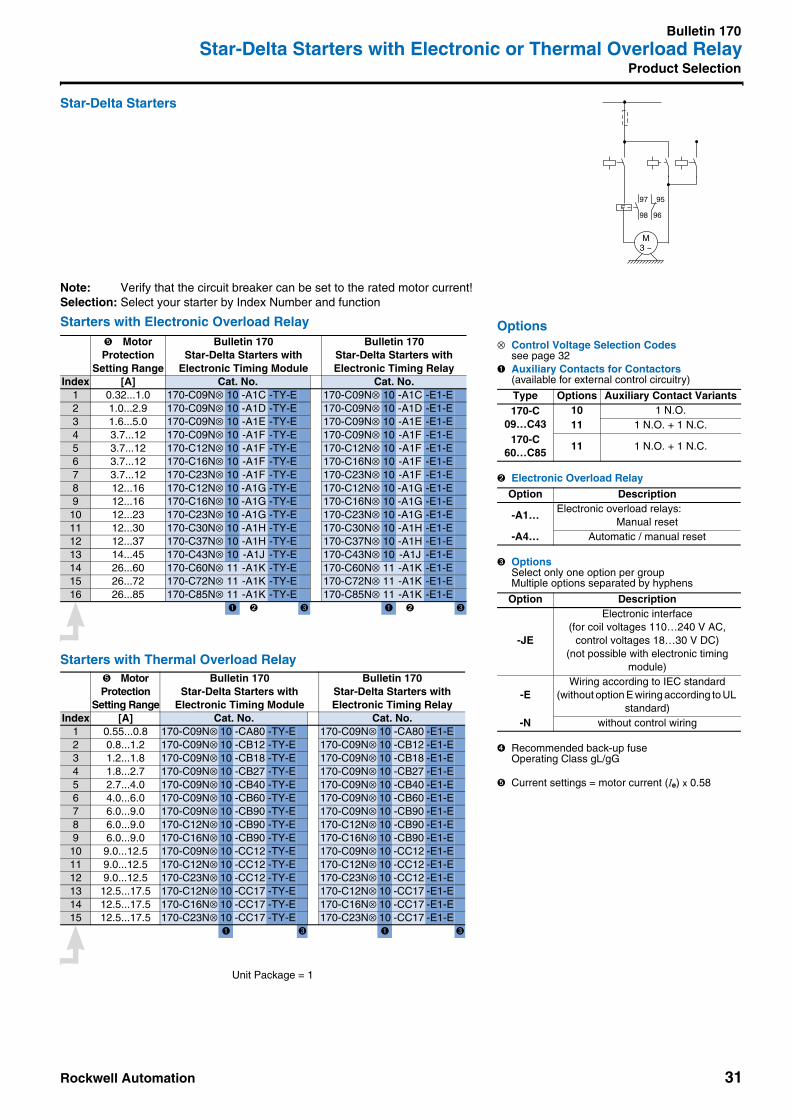
Bulletin 170Star-Delta Starters with Electronic or Thermal Overload RelayProduct Selection
Star-Delta Starters • Short-Circuit Coordination Type "2" according to IEC 60947-4-1• Starters in enclosure with 100-C contactors, 193-EA electronic or 193-CT thermal overload relay• Completely assembled with main current connections• With mechanical and electrical interlock• IEC and UL/CSA compliant• Mounting versions: please refer to pages 8 and 9
-Snap on 1 top hat rail 35 mm or screw fixing
Note: Line voltage and short-circuit coordination see MCS Star or catalog A114Selection: Find the correct Index Number considering motor rating and line voltage
Starters with Electronic Overload Relay
Starters with Thermal Overload Relay
Standard MotorsAC-3, 3phase
230 V 400 / 415 V 500 V 690 VFuse ➍ Fuse ➍ Fuse ➍ Fuse ➍
[kW] Index [A] Index [A] Index [A] Index [A]0.75 2 6 2 4 1 4 1 21.1 3 10 2 4 2 4 1 41.5 3 10 2 6 2 4 2 42.2 4 16 3 10 2 6 2 43.0 4 16 3 10 3 10 2 64.0 4 20 4 16 3 10 3 105.5 4 25 4 16 4 16 3 106.3 8 32 4 20 4 16 3 167.5 8 32 4 20 4 16 4 16
10.0 10 40 5 32 5 20 5 2011.0 10 40 9 32 5 25 6 2015.0 11 63 10 40 9 32 7 2518.5 12 80 10 40 10 32 10 3222 13 80 11 50 10 40 11 3225 13 100 11 63 11 50 11 4030 14 125 12 63 12 50 12 4037 15 125 13 80 13 63 13 5045 16 160 14 100 13 80 14 6355 14 125 14 100 14 8063 15 125 14 125 15 10075 16 160 15 125 16 10090 16 160
Standard MotorsAC-3, 3phase
230 V 400 / 415 V 500 V 690 VFuse ➍ Fuse ➍ Fuse ➍ Fuse ➍
[kW] Index [A] Index [A] Index [A] Index [A]0.75 4 6 2 4 2 4 1 21.1 4 10 3 4 3 4 2 41.5 5 10 4 6 3 4 3 42.2 6 16 5 10 4 6 3 43.0 7 16 5 10 5 10 4 64.0 7 20 6 16 5 10 5 105.5 10 25 7 16 6 16 5 106.3 13 32 7 20 6 16 6 167.5 13 32 7 20 7 16 6 16
10.0 11 32 11 20 8 2011.0 14 32 11 25 9 2015.0 15 40 14 32 12 2518.5 15 32 15 32
170…
Hp ratings anddimensions - see MCS Star
Rockwell Automation 31
Bulletin 170Star-Delta Starters with Electronic or Thermal Overload Relay
Product Selection
Star-Delta Starters
Note: Verify that the circuit breaker can be set to the rated motor current!Selection: Select your starter by Index Number and function
Starters with Electronic Overload Relay
Starters with Thermal Overload Relay
➎ MotorProtection
Setting Range
Bulletin 170Star-Delta Starters with
Electronic Timing Module
Bulletin 170Star-Delta Starters withElectronic Timing Relay
Index [A] Cat. No. Cat. No.1 0.32...1.0 170-C09N⊗ 10 -A1C -TY-E 170-C09N⊗ 10 -A1C -E1-E2 1.0...2.9 170-C09N⊗ 10 -A1D -TY-E 170-C09N⊗ 10 -A1D -E1-E3 1.6...5.0 170-C09N⊗ 10 -A1E -TY-E 170-C09N⊗ 10 -A1E -E1-E4 3.7...12 170-C09N⊗ 10 -A1F -TY-E 170-C09N⊗ 10 -A1F -E1-E5 3.7...12 170-C12N⊗ 10 -A1F -TY-E 170-C12N⊗ 10 -A1F -E1-E6 3.7...12 170-C16N⊗ 10 -A1F -TY-E 170-C16N⊗ 10 -A1F -E1-E7 3.7...12 170-C23N⊗ 10 -A1F -TY-E 170-C23N⊗ 10 -A1F -E1-E8 12...16 170-C12N⊗ 10 -A1G -TY-E 170-C12N⊗ 10 -A1G -E1-E9 12...16 170-C16N⊗ 10 -A1G -TY-E 170-C16N⊗ 10 -A1G -E1-E
10 12...23 170-C23N⊗ 10 -A1G -TY-E 170-C23N⊗ 10 -A1G -E1-E11 12...30 170-C30N⊗ 10 -A1H -TY-E 170-C30N⊗ 10 -A1H -E1-E12 12...37 170-C37N⊗ 10 -A1H -TY-E 170-C37N⊗ 10 -A1H -E1-E13 14...45 170-C43N⊗ 10 -A1J -TY-E 170-C43N⊗ 10 -A1J -E1-E14 26...60 170-C60N⊗ 11 -A1K -TY-E 170-C60N⊗ 11 -A1K -E1-E15 26...72 170-C72N⊗ 11 -A1K -TY-E 170-C72N⊗ 11 -A1K -E1-E16 26...85 170-C85N⊗ 11 -A1K -TY-E 170-C85N⊗ 11 -A1K -E1-E
➊ ➋ ➌ ➊ ➋ ➌
➎ MotorProtection
Setting Range
Bulletin 170Star-Delta Starters with
Electronic Timing Module
Bulletin 170Star-Delta Starters withElectronic Timing Relay
Index [A] Cat. No. Cat. No.1 0.55...0.8 170-C09N⊗ 10 -CA80 -TY-E 170-C09N⊗ 10 -CA80 -E1-E2 0.8...1.2 170-C09N⊗ 10 -CB12 -TY-E 170-C09N⊗ 10 -CB12 -E1-E3 1.2...1.8 170-C09N⊗ 10 -CB18 -TY-E 170-C09N⊗ 10 -CB18 -E1-E4 1.8...2.7 170-C09N⊗ 10 -CB27 -TY-E 170-C09N⊗ 10 -CB27 -E1-E5 2.7...4.0 170-C09N⊗ 10 -CB40 -TY-E 170-C09N⊗ 10 -CB40 -E1-E6 4.0...6.0 170-C09N⊗ 10 -CB60 -TY-E 170-C09N⊗ 10 -CB60 -E1-E7 6.0...9.0 170-C09N⊗ 10 -CB90 -TY-E 170-C09N⊗ 10 -CB90 -E1-E8 6.0...9.0 170-C12N⊗ 10 -CB90 -TY-E 170-C12N⊗ 10 -CB90 -E1-E9 6.0...9.0 170-C16N⊗ 10 -CB90 -TY-E 170-C16N⊗ 10 -CB90 -E1-E
10 9.0...12.5 170-C09N⊗ 10 -CC12 -TY-E 170-C09N⊗ 10 -CC12 -E1-E11 9.0...12.5 170-C12N⊗ 10 -CC12 -TY-E 170-C12N⊗ 10 -CC12 -E1-E12 9.0...12.5 170-C23N⊗ 10 -CC12 -TY-E 170-C23N⊗ 10 -CC12 -E1-E13 12.5...17.5 170-C12N⊗ 10 -CC17 -TY-E 170-C12N⊗ 10 -CC17 -E1-E14 12.5...17.5 170-C16N⊗ 10 -CC17 -TY-E 170-C16N⊗ 10 -CC17 -E1-E15 12.5...17.5 170-C23N⊗ 10 -CC17 -TY-E 170-C23N⊗ 10 -CC17 -E1-E
➊ ➌ ➊ ➌
Options⊗ Control Voltage Selection Codes
see page 32➊ Auxiliary Contacts for Contactors
(available for external control circuitry)
➋ Electronic Overload Relay
➌ OptionsSelect only one option per groupMultiple options separated by hyphens
➍ Recommended back-up fuseOperating Class gL/gG
➎ Current settings = motor current (Ie) x 0.58
Type Options Auxiliary Contact Variants170-C
09…C4310 1 N.O.11 1 N.O. + 1 N.C.
170-C60…C85
11 1 N.O. + 1 N.C.
Option Description
-A1…Electronic overload relays:
Manual reset-A4… Automatic / manual reset
Option Description
-JE
Electronic interface(for coil voltages 110…240 V AC,
control voltages 18…30 V DC)(not possible with electronic timing
module)
-EWiring according to IEC standard
(without option E wiring according to UL standard)
-N without control wiring
M3 ~
97 95
98 96
Unit Package = 1

Bulletin 103S, 107S, 103T, 107T, 109, 105, 170, 190S, 191S, 190E, 191EStarters
32 Rockwell Automation
Control Voltage Selection Codes
Voltage codes in bold type: Preferred products( ) Voltage codes in parentheses: No inventory (longer delivery time)
➊ Extended operation limits 0.65…1.3 x Us➋ Extended operation limits 0.7…1.25 x Us
190E, 191E
[V] 24 48 110110-120
220-230
230230-240
240380-400
400-415
50 Hz — — D — (A) — — — KK60 Hz — — D — — (A) — — KK50/60 Hz KD KH — — — KF — (KT) — —
103S, 107S,103T, 107T,190S, 191S,105, 109, 170
[V] 12 24 32 36 42 48 100100-110
110 120 127 200200-220
200-230
208-240
50 Hz (R) (K) (V) (W) (X) (Y) (KP) — (D) (P) (S) (KG) — — —60 Hz (Q) (J) — (V) — (X) — (KP) — (D) — — (KG) — (L)50/60 Hz — KJ — — — KY (KP) — KD — — (KG) — (KL) —
220-230
230230-240
240 277 347 380380-400
400400-415
440 480 500 550 600
50 Hz (F) — (VA) (T) — — — (N) — (G) (B) — (M) (C) —60 Hz — — — (A) (T) (I) (E) — — — (N) (B) — — (C)50/60 Hz — KF — (KA) — — — — KN — (KB) — — — —
190E, 191E
[V] 24 48 110 220
DC Z24 (Z48) Z11 (Z2)with diode protective circuit DC ZD24 — — —
1...-C09…C43
[V] 9➊ 12 24➋ 36 48 60 64 72 80 110 115 125 220 230 250
DC (ZR) (ZQ) — (ZW) (ZY) (ZZ) (ZB) (ZG) (ZE) ZD (ZP) (ZS) (ZA) (ZF) (ZT)with diode protective circuit DC — — DJ — — — — — — — — — — — —
1...-C60…C85 DC — — — — — — — — — — — — — — —with diode protective circuit DC (DR) (DQ) DJ (DW) (DY) (DZ) (DB) (DG) (DE) DD (DP) (DS) (DA) (DF) (DT)
⊗ Control Voltage Selection Codes for AC Control
⊗ Control Voltage Selection Codes for DC Control

Rockwell Automation 33
Bulletin 141AMounting System
Bulletin 141AMounting System
• Modular• Reduces Installation Time• Component Modules Easily Added
and Removed• Pre-assembly of Starters of any kind• Pluggable Control Connections• Ease of Commissioning and Testing• Standard Modules Pluggable• IsoTM Modules for highest Operator
Safety• Mounting Modules for Top Hat Rail
and Screw Mounting
TABLE OF CONTENTSDescription Page Description PageOverview . . . . . . . . . . . . . . . . . . . . . . . . . . . . . . . . . . . . . . . . . . . . 2…9Product Selection
MCS IsoTM Busbar Modules . . . . . . . . . . . . . . . . . . . . . . . . . . . . . 34MCS Standard Busbar Modules . . . . . . . . . . . . . . . . . . . . . . . . . . 35MCS Mounting Modules . . . . . . . . . . . . . . . . . . . . . . . . . . . . . . . . 37
Accessories. . . . . . . . . . . . . . . . . . . . . . . . . . . . . . . . . . . . . . . . . . . . 40
SpecificationsPanel Mounting System . . . . . . . . . . . . . . . . . . . . . . . . . . . . . . . .41Standards and Approvals . . . . . . . . . . . . . . . . . . . . . . . . . . . . . . .41
Dimensions . . . . . . . . . . . . . . . . . . . . . . . . . . . . . . . . . . see MCS Star
Bulletin 141AMounting System
34 Rockwell Automation
Product Selection
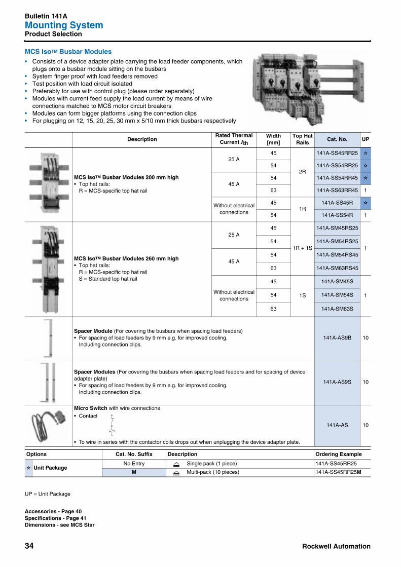
MCS IsoTM Busbar Modules • Consists of a device adapter plate carrying the load feeder components, which
plugs onto a busbar module sitting on the busbars• System finger proof with load feeders removed • Test position with load circuit isolated• Preferably for use with control plug (please order separately)• Modules with current feed supply the load current by means of wire
connections matched to MCS motor circuit breakers• Modules can form bigger platforms using the connection clips• For plugging on 12, 15, 20, 25, 30 mm x 5/10 mm thick busbars respectively
DescriptionRated Thermal
Current IthWidth[mm]
Top HatRails
Cat. No. UP
MCS IsoTM Busbar Modules 200 mm high• Top hat rails:
R = MCS-specific top hat rail
25 A45
2R
141A-SS45RR25 ✫
54 141A-SS54RR25 ✫
45 A54 141A-SS54RR45 ✫
63 141A-SS63RR45 1
Without electricalconnections
451R
141A-SS45R ✫
54 141A-SS54R 1
MCS IsoTM Busbar Modules 260 mm high• Top hat rails:
R = MCS-specific top hat railS = Standard top hat rail
25 A45
1R + 1S
141A-SM45RS25
154 141A-SM54RS25
45 A54 141A-SM54RS45
63 141A-SM63RS45
Without electricalconnections
45
1S
141A-SM45S
154 141A-SM54S
63 141A-SM63S
Spacer Module (For covering the busbars when spacing load feeders)• For spacing of load feeders by 9 mm e.g. for improved cooling.
Including connection clips.141A-AS9B 10
Spacer Modules (For covering the busbars when spacing load feeders and for spacing of device adapter plate)• For spacing of load feeders by 9 mm e.g. for improved cooling.
Including connection clips.
141A-AS9S 10
Micro Switch with wire connections
• Contact
• To wire in series with the contactor coils drops out when unplugging the device adapter plate.
141A-AS 10
Options Cat. No. Suffix Description Ordering Example
✫ Unit PackageNo Entry Single pack (1 piece) 141A-SS45RR25
M Multi-pack (10 pieces) 141A-SS45RR25M
UP = Unit Package
Accessories - Page 40Specifications - Page 41Dimensions - see MCS Star
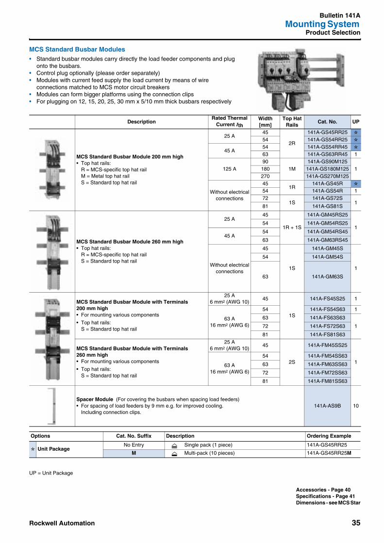
Rockwell Automation 35
Bulletin 141AMounting System
Product Selection
MCS Standard Busbar Modules • Standard busbar modules carry directly the load feeder components and plug
onto the busbars.• Control plug optionally (please order separately)• Modules with current feed supply the load current by means of wire
connections matched to MCS motor circuit breakers• Modules can form bigger platforms using the connection clips• For plugging on 12, 15, 20, 25, 30 mm x 5/10 mm thick busbars respectively
DescriptionRated Thermal
Current IthWidth[mm]
Top HatRails
Cat. No. UP
MCS Standard Busbar Module 200 mm high• Top hat rails:
R = MCS-specific top hat railM = Metal top hat railS = Standard top hat rail
25 A45
2R
141A-GS45RR25 ✫
54 141A-GS54RR25 ✫
45 A54 141A-GS54RR45 ✫
63 141A-GS63RR45 1
125 A90
1M141A-GS90M125
1180 141A-GS180M125270 141A-GS270M125
Without electricalconnections
451R
141A-GS45R ✫
54 141A-GS54R 172
1S141A-GS72S
181 141A-GS81S
MCS Standard Busbar Module 260 mm high• Top hat rails:
R = MCS-specific top hat railS = Standard top hat rail
25 A45
1R + 1S
141A-GM45RS25
154 141A-GM54RS25
45 A54 141A-GM54RS45
63 141A-GM63RS45
Without electricalconnections
45
1S
141A-GM45S
1
54 141A-GM54S
63 141A-GM63S
MCS Standard Busbar Module with Terminals200 mm high• For mounting various components
• Top hat rails:S = Standard top hat rail
25 A6 mm2 (AWG 10)
45
1S
141A-FS45S25 1
63 A16 mm2 (AWG 6)
54 141A-FS54S63 1
63 141A-FS63S63
172 141A-FS72S63
81 141A-FS81S63
MCS Standard Busbar Module with Terminals260 mm high• For mounting various components
• Top hat rails:S = Standard top hat rail
25 A6 mm2 (AWG 10)
45
2S
141A-FM45SS25
163 A
16 mm2 (AWG 6)
54 141A-FM54SS63
63 141A-FM63SS63
72 141A-FM72SS63
81 141A-FM81SS63
Spacer Module (For covering the busbars when spacing load feeders)• For spacing of load feeders by 9 mm e.g. for improved cooling.
Including connection clips.141A-AS9B 10
Options Cat. No. Suffix Description Ordering Example
✫ Unit PackageNo Entry Single pack (1 piece) 141A-GS45RR25
M Multi-pack (10 pieces) 141A-GS45RR25M
UP = Unit Package
Accessories - Page 40Specifications - Page 41Dimensions - see MCS Star

Bulletin 141AMounting System
36 Rockwell Automation
Product Selection
MCS Standard Busbar Modules >100 A • Busbar modules > 100 A are screw mounted onto the busbars• Sliding nuts for matching the fixing positions of components• Terminal positions available on top or bottom• For mounting components with current ratings > 100 A (supply and load feeders)
DescriptionHeight[mm]
Rated Thermal Current Ith
Width[mm]
Wire Size[mm2](AWG)
Cat. No. UP
MCS Standard Busbar Modules with box terminals on top
222 200 A 1086 … 70
(AWG 16…00)141A-FS108V200T
1
320 250 A 11035 … 120
(AWG 2…4/0)141A-FL110V250T
MCS Standard Busbar Modules with box terminals on bottom
222 200 A 1086 … 70
(AWG 16…00)141A-FS108V200B
320 250 A 11035 … 120
(AWG 2…4/0)141A-FL110V250B
UP = Unit Package
Accessories - Page 40Specifications - Page 41Dimensions - see MCS Star

Rockwell Automation 37
Bulletin 141AMounting System
Product Selection
MCS Mounting Modules • Modules (carrying the load feeder components) for screw mounting or snapping
onto top hat (DIN) rails.• Control plug optionally (please order separately)• Three module lengths for 2- and 3-component starters.• Modules can form bigger platforms using the connection clips (see accessories)• Modules with PE - terminal for termination of the motor leads incl. PE (for mounting
on top hat rails only).
➊ Ith = Rated thermal current
DescriptionHeight[mm]
Width[mm]
Top HatRails
Cat. No. UP
MCS Mounting Module• Top hat rails:
R = MCS-specific top hat rail
• 228 mm high; preferably for 2-component starters
• 283 mm high; preferably for 3-component starters 193-EA/EB
• 333 mm high; preferably for 3-component starters 193-EC
228
45
2R
141A-WS45RR ✫
54 141A-WS54RR ✫
283
45
2R
141A-WM45RR ✫
54 141A-WM54RR ✫
333
45
2R
141A-WL45RR
1
54 141A-WL54RR
MCS Mounting Module with PE-terminal• Top hat rails:
R = MCS-specific top hat rail
• 228 mm high; preferably for 2-component starters
• 283 mm high; preferably for 3-component starters 193-EA/EB
• 333 mm high; preferably for 3-component starters 193-EC
228
45
2R
141A-WS45RRP ✫
54 141A-WS54RRP ✫
283
45
2R
141A-WM45RRP ✫
54 141A-WM54RRP ✫
333
45
2R
141A-WL45RRP
1
54 141A-WL54RRP
Spacer Module• For spacing of load feeders by 9 mm e.g. for improved cooling.
Including connection clips.141A-AS9W 10
Options Cat. No. Suffix Description Ordering Example
✫ Unit PackageNo Entry Single pack (1 piece) 141A-WS45RR
M Multi-pack (10 pieces) 141A-WS45RRM
UP = Unit Package
Accessories - Page 40Specifications - Page 41Dimensions - see MCS Star

Bulletin 141AMounting System
38 Rockwell Automation
Product Selection
Busbar Components
DescriptionBusbar[mm]
Cat. No. UP
Busbar Supports• 60 mm pole centre spacing
• The busbar support can easily be adjusted to the busbar size via the integral slide rail.
3-pole
12, 15, 20, 25, 30 x 5/10
141A-TR3 10
4-pole 141A-TR4 10
1-pole 141A-TR1 10
Busbar End Covers• Prevents from contact with the busbar ends
• The end cover can easily be clipped on the busbar support.
3-pole 141A-TR3E 10
4-pole 141A-TR4E 10
Feeder Busbar Support• For 3-pole supply
• 60 mm pole centre spacing1.5…16 mm2 (AWG 16…6)
12, 15, 20, 25, 30 x 5/10
141A-TR3F16 10
Supply Modules• For 3-pole supply
• 60 mm pole centre spacing
6…70 mm2 (AWG 10…00)54 mm wide
12…30 x 5or
12…30 x 10
141A-VN370
1
35…120 mm2 (AWG 2…MCM 250)81 mm wide
141A-VN3120
95…185 mm2 (AWG 3/0…MCM 350)135 mm wide
141A-VN3185
150…300 mm2 (MCM 300…600)135 mm wide
141A-VN3300R
Laminated copper:3 x 20 x 1…10 x 32 x 1 mm
135 mm wide141A-VN3300F
Single Terminals• Single terminals for supplying busbars
2.5…16 mm2 (AWG 14…6)12…30 x 5 141A-VS116 25
12…30 x 10 141A-VS216 25
4…35 mm2 (AWG 12…2)12…30 x 5 141A-VS135 25
12…30 x 10 141A-VS235 25
16…70 mm2 (AWG 6…00)12…30 x 5 141A-VS170 25
12…30 x 10 141A-VS270 25
Terminal Cover• Finger protection when busbars supplied with single terminals.
• Fixable on busbar with plastic lock.
• Height: 180 mm, wide: 54 mm
12…30 x 5or
12…30 x 10141A-BK1 1
UP = Unit Package
Accessories - Page 40Specifications - Page 41Dimensions - see MCS Star

Rockwell Automation 39
Bulletin 141AMounting System
Product Selection
Busbar Components
DescriptionBusbar[mm]
Cat. No. UP
Busbar Connectors• For connection of busbar racks with same dimensions
Distance of systems 5…10 mm
12…20 x 5 or
12…20 x 10141A-VC3A 12
13…20 mm
20…30 x 5 or
20…30 x 10
141A-VC3B 6
50…60 mm 141A-VC3C 3
100…110 mm 141A-VC3D 3
Single Pole Busbar Covers• Snap-on profile for single busbars for protection against electric shock.
• Length: 1 m, can be cut to length.
12…30 x 5 141A-BS5
10
12…30 x 10 141A-BS10
Three Pole Busbar Shroud• Covers all three busbars for protection against electric shock.
• 200 x 1100 mm
• Cover to be cut to length
141A-BCF1 2
Busbar Shroud Holder• Use together with busbar shroud
(2 required for 1 cover)
12…30 x 5 or
12…30 x 10141A-BCF1H 10
UP = Unit Package
Accessories - Page 40Specifications - Page 41Dimensions - see MCS Star

Bulletin 141AMounting System
40 Rockwell Automation
Accessories
Accessories
DescriptionSize[mm]
Cat. No. UP
Device RailsIsoTM, standard and mounting modules
➊ R = MCS-specific top hat rail
➋ S = Standard top hat rail
Plastic top hat rail specific for MCS components
45 141A-AHR45
10
54 141A-AHR54
63 141A-AHR63
Plastic top hat rail standard for universal use
45 141A-AHS45
10
54 141A-AHS54
63 141A-AHS63
72 141A-AHS72
81 141A-AHS81
Metal top hat rail
90 141A-AHM90
10171 141A-AHM171
252 141A-AHM252
Carrier for Top Hat Rail• Carrier for top hat rails inclusive screws, fits on the standard top hat rails.
For screw mounting of metal top hat rails on bigger devices.54 141A-AHH54 10
Control Plugs• Allows fast and simple connection of control
wiring.
• Comprises plug holders and male and female plug
• To snap onto IsoTM, standard and mounting modules
8-pole control plug 141A-APC8 ✫
10-pole control plug 141A-APC10 ✫
12-pole control plug 141A-APC12 ✫
Control Plug Holder• Receives Wago control plugs with catches
and Wago Cage Clamp connections.
• To snap onto IsoTM, standard or mounting modules
Wago catalog number:female plug 232-2##/026-000male plug 231-6##/018-000
141A-APH 10
Connection Clip• For joining modules
141A-AK 50
Instruction label• Self-adhesive application instruction
141A-AI 10
Options Cat. No. Suffix Description Ordering Example
✫ Unit PackageNo Entry Single pack (1 piece) 141A-APC8
M Multi-pack (10 pieces) 141A-APC8M
➊
➋
UP = Unit Package
Product Selection - Page 34
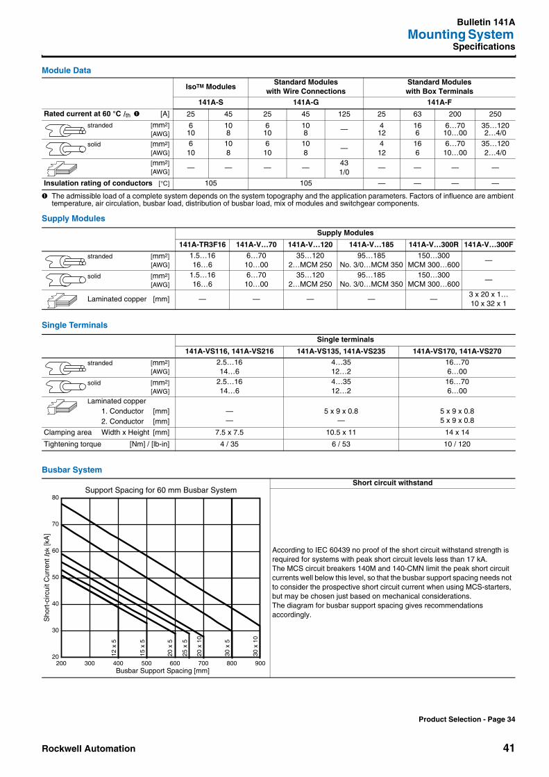
Rockwell Automation 41
Bulletin 141AMounting System
Specifications
Module Data
➊ The admissible load of a complete system depends on the system topography and the application parameters. Factors of influence are ambient temperature, air circulation, busbar load, distribution of busbar load, mix of modules and switchgear components.
Supply Modules
Single Terminals
Busbar System
IsoTM ModulesStandard Modules
with Wire ConnectionsStandard Modules with Box Terminals
141A-S 141A-G 141A-F
Rated current at 60 °C Ith ➊ [A] 25 45 25 45 125 25 63 200 250
stranded [mm2][AWG]
610
108
610
108 — 4
12166
6…7010…00
35…1202…4/0
solid [mm2][AWG]
610
108
610
108
—4
12166
6…7010…00
35…1202…4/0
[mm2][AWG]
— — — —431/0
— — — —
Insulation rating of conductors [°C] 105 105 — — — —
Supply Modules
141A-TR3F16 141A-V…70 141A-V…120 141A-V…185 141A-V…300R 141A-V…300F
stranded [mm2][AWG]
1.5…1616…6
6…7010…00
35…1202…MCM 250
95…185No. 3/0…MCM 350
150…300MCM 300…600
—
solid [mm2][AWG]
1.5…1616…6
6…7010…00
35…1202…MCM 250
95…185No. 3/0…MCM 350
150…300MCM 300…600
—
Laminated copper [mm] — — — — —3 x 20 x 1…10 x 32 x 1
Single terminals
141A-VS116, 141A-VS216 141A-VS135, 141A-VS235 141A-VS170, 141A-VS270
stranded [mm2][AWG]
2.5…1614…6
4…3512…2
16…706…00
solid [mm2][AWG]
2.5…1614…6
4…3512…2
16…706…00
Laminated copper1. Conductor [mm]2. Conductor [mm]
——
5 x 9 x 0.8—
5 x 9 x 0.85 x 9 x 0.8
Clamping area Width x Height [mm] 7.5 x 7.5 10.5 x 11 14 x 14
Tightening torque [Nm] / [lb-in] 4 / 35 6 / 53 10 / 120
Short circuit withstand
According to IEC 60439 no proof of the short circuit withstand strength is required for systems with peak short circuit levels less than 17 kA.The MCS circuit breakers 140M and 140-CMN limit the peak short circuit currents well below this level, so that the busbar support spacing needs not to consider the prospective short circuit current when using MCS-starters, but may be chosen just based on mechanical considerations. The diagram for busbar support spacing gives recommendations accordingly.
Support Spacing for 60 mm Busbar System
20
30
40
50
60
70
80
200 300 400 500 600 700 800 900Busbar Support Spacing [mm]
Sho
rt-c
ircui
t Cur
rent
Ipk
[kA
]
30 x
10
20 x
10
30 x
5
25 x
5
20 x
5
15 x
5
12 x
5
Product Selection - Page 34
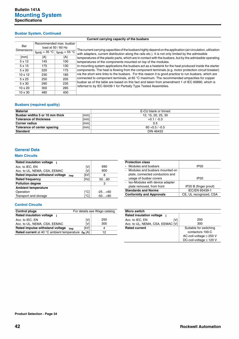
Bulletin 141AMounting System
42 Rockwell Automation
Specifications
Busbar System, Continued
Busbars (required quality)
General DataMain Circuits
Control Circuits
Current carrying capacity of the busbars
BarDimensions
Recommended max. busbarload at 50 / 60 Hz
The current carrying capacities of the busbars highly depend on the application (air circulation, utilization with adapters, current distribution along the rails etc.). It is not only limited by the admissible temperatures of the plastic parts, which are in contact with the busbars, but by the admissible operating temperatures of the components mounted on top of the modules.In mounting system applications the busbars act as a heatsink for the heat produced inside the starter components. The heat is flowing from the component terminals (e.g. motor protection circuit breaker) via the short wire links to the busbars. For this reason it is good practice to run busbars, which are connected to component terminals, at 65 °C maximum. The recommended ampacities for copper busbar as of the table are based on this fact and taken from amendment 1 of IEC 60890, which is referred to by IEC 60439-1 for Partially Type Tested Assemblies.
tamb = 35 °C tamb = 55 °C
[mm] [A] [A]5 x 12 145 1005 x 15 175 1305 x 20 220 175
10 x 12 230 1855 x 25 250 2055 x 30 290 235
10 x 20 350 28510 x 30 480 400
Material E-CU blank or tinnedBusbar widths 5 or 10 mm thick [mm] 12, 15, 20, 25, 30Tolerance of thickness [mm] +0.1 / -0.3Corner radius [mm] 0.5Tolerance of center spacing [mm] 60 +0.5 / -0.5Standard DIN 46433
Rated insulation voltage iAcc. to IEC, EN [V]Acc. to UL, NEMA, CSA, EEMAC [V]
690600
Rated impulse withstand voltage imp [kV] 8Rated frequency [Hz] 50…60Pollution degree 3Ambient temperatureOperation [°C]Transport and storage [°C]
-25…+60-50…+80
Protection class- Modules and busbars IP00- Modules and busbars mounted on
plate, connected conductors and usage of busbar covers IP20
- Iso-Modules with device adapter plate removed, from front IP20 B (finger proof)
Standards and Norms IEC/EN 60439-1Conformity and Approvals CE, UL recognized, CSA
Control plugs For details see Wago catalogRated insulation voltage iAcc. to IEC, EN [V]Acc. to UL, NEMA, CSA, EEMAC [V]
250300
Rated impulse withstand voltage imp [kV] 4Rated current at 40 °C ambient temperature Ith [A] 12
Micro switchRated insulation voltage iAcc. to IEC, EN [V]Acc. to UL, NEMA, CSA, EEMAC [V]
250300
Rated current Suitable for switching contactors 100-C
AC-coil-voltage ≤ 250 VDC-coil-voltage ≤ 120 V
Product Selection - Page 34
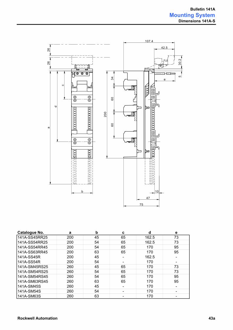
Bulletin 141AMounting System
Dimensions 141A-S
Catalogue No. a b c d e141A-SS45RR25 200 45 65 162.5 73141A-SS54RR25 200 54 65 162.5 73141A-SS54RR45 200 54 65 170 95141A-SS63RR45 200 63 65 170 95141A-SS45R 200 45 - 162.5 -141A-SS54R 200 54 - 170 -141A-SM45RS25 260 45 65 170 73141A-SM54RS25 260 54 65 170 73141A-SM54RS45 260 54 65 170 95141A-SM63RS45 260 63 65 170 95141A-SM45S 260 45 - 170 -141A-SM54S 260 54 - 170 -141A-SM63S 260 63 - 170 -
Rockwell Automation 43a
c
a
3460
60
47
75
26
b
e
10
d
200
107.4
42.5
30.2
26
5

Bulletin 141AMounting SystemDimensions 141A-G
Catalogue No. a b c d e141A-GS45RR25 200 45 65 162.5 73141A-GS54RR25 200 54 65 162.5 73141A-GS54RR45 200 54 65 170 95141A-GS63RR45 200 63 65 170 95141A-GS45R 200 45 - 162.5 -141A-GS54R 200 54 - 170 -141A-GS72S 200 72 105 - -141A-GS81S 200 81 105 - -141A-GM45RS25 260 45 65 170 73141A-GM54RS25 260 54 65 170 73141A-GM54RS45 260 54 65 170 95141A-GM63RS45 260 63 65 170 95141A-GM45S 260 45 - 170 -141A-GM54S 260 54 - 170 -141A-GM63S 260 63 - 170 -
43b Rockwell Automation
a
b
c
60
63
35
3460
e
10
d
200
72.5
19.5
30.2
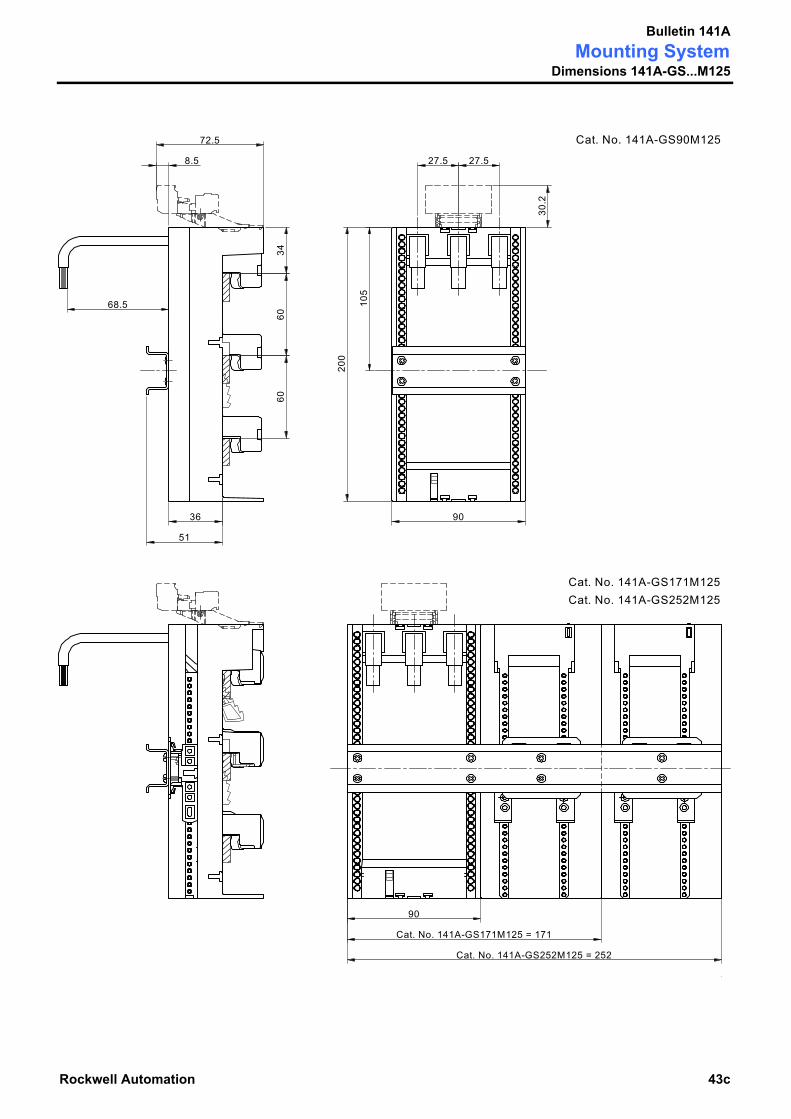
Bulletin 141AMounting System
Dimensions 141A-GS...M125
Rockwell Automation 43c
30.2
8.5 27.5 27.5
68.5 105
200
90
3460
60
36
51
72.5
90
Cat. No. 141A-GS171M125 = 171
Cat. No. 141A-GS252M125 = 252
Cat. No. 141A-GS171M125Cat. No. 141A-GS252M125
Cat. No. 141A-GS90M125

Bulletin 141AMounting SystemDimensions 141A-F
Catalogue No. a b c d141A-FS45S25 200 45 65 - 6mm² AWG 10141A-FS54S63 200 54 65 - 16mm² AWG 6141A-FS63S63 200 63 65 - 16mm² AWG 6141A-FS72S63 200 72 65 - 16mm² AWG 6141A-FS81S63 200 81 65 - 16mm² AWG 6141A-FM45SS25 260 45 65 170 6mm² AWG 10141A-FM54SS63 260 54 65 170 16mm² AWG 6141A-FM63SS63 260 63 65 170 16mm² AWG 6141A-FM72SS63 260 72 65 170 16mm² AWG 6141A-FM81SS63 260 81 65 170 16mm² AWG 6
43d Rockwell Automation
Wire Sizes
30.2
d
200
72.5
19.5
a
b
c
60
63
35
3460
10
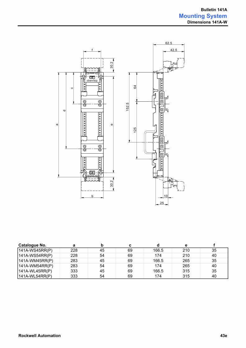
Bulletin 141AMounting System
Dimensions 141A-W
Catalogue No. a b c d e f141A-WS45RR(P) 228 45 69 166.5 210 35141A-WS54RR(P) 228 54 69 174 210 40141A-WM45RR(P) 283 45 69 166.5 265 35141A-WM54RR(P) 283 54 69 174 265 40141A-WL45RR(P) 333 45 69 166.5 315 35141A-WL54RR(P) 333 54 69 174 315 40
Rockwell Automation 43e
42.5
30.2
30.2
25
152.
5
6412
5
f
e
d
62.5
c
a
b
oben/top
10
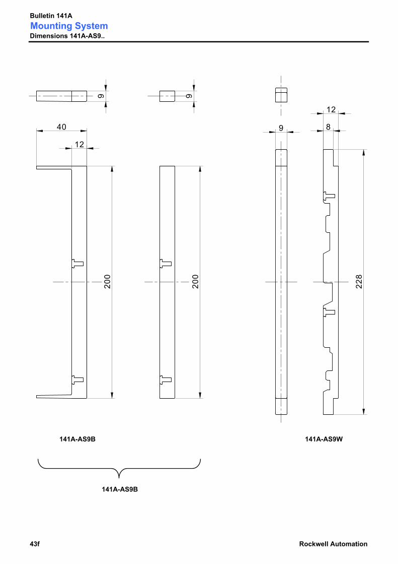
Bulletin 141AMounting SystemDimensions 141A-AS9..
141A-AS9B
141A-AS9B
43f Rockwell Automation
141A-AS9W
12
40
9200
200
9
8
12
228
9

Bulletin 141AMounting SystemDimensions 141A-APC...
8 Poles 10 Poles 12 Poles
Rockwell Automation 43g
72.262
.5
30.2
24.3
41.5 51.5 61.5
43.5 53.5 63.5
31.5
48.5
58.2
27.5
14.3
22.4
14.3
10

Bulletin 141AMounting System
Dimensions 141A-TR...
141A-TR3
141A-TR4
43h Rockwell Automation
141A-TR3F16 141A-TR3E
141A-TR4E 141A-TR1
20
75
6060
17.5
185
23
28
51
20
17.5
185
6060
75
202
5 31
166
6060
60
51
28
23
245
17.5
125
5 31
226
20
26
63 50 63
51
36.5
Ø 6
.5
Ø 6
.5
12.5
Ø 6
.5
12.5
27

Rockwell Automation 43i
Bulletin 141AMounting System
Specifications
Dimensions see MCS Star
Weight [g] MCS IsoTM
Busbar Module[g]
MCS StandardBusbar Module
[g]MCS Standard
Busbar Module >100 A[g]
BusbarComponents
[g] Accessories [g]
141A-SS45RR25 381 141A-GS45RR25 302 141A-FS108V200T 1000 141A-TR3 203 141A-AHR45 15141A-SS54RR25 396 141A-GS54RR25 347 141A-FL110V250T 1200 141A-TR4 256 141A-AHR54 16141A-SS54RR45 472 141A-GS54RR45 358 141A-FS108V200B 1000 141A-TR1 59 141A-AHR63 16141A-SS63RR45 480 141A-GS63RR45 379 141A-FL110V250B 1200 141A-TR3E 21 141A-AHS45 15141A-SS45R 279 141A-GS90M125 781 141A-TR4E 28 141A-AHS54 16141A-SS54R 305 141A-GS180M125 1021 MCS
Mounting Module[g]
141A-TR3F16 285 141A-AHS63 16141A-SM45RS25 402 141A-GS270M125 1271 141A-VN370 360 141A-AHS72 17141A-SM54RS25 418 141A-GS45R 200 141A-WS45RR 163 141A-VN3120 485 141A-AHS81 18141A-SM54RS45 494 141A-GS54R 226 141A-WS54RR 204 141A-VN3185 1140 141A-AHM90 65141A-SM63RS45 502 141A-GS72S 268 141A-WM45RR 189 141A-VN3300R 1540 141A-AHM171 122141A-SM45S 300 141A-GS81S 289 141A-WM54RR 211 141A-VN3300F 1619 141A-AHM252 180141A-SM54S 327 141A-GM45RS25 313 141A-WL45RR 211 141A-VS116 21 141A-AHH54 19141A-SM63S 405 141A-GM54RS25 368 141A-WL54RR 222 141A-VS216 23 141A-APC8 29
141A-GM54RS45 379 141A-WS45RRP 180 141A-VS135 46 141A-APC10 35141A-GM63RS45 400 141A-WS54RRP 221 141A-VS235 47 141A-APC12 40141A-GM45S 211 141A-WM45RRP 212 141A-VS170 71 141A-APH 5141A-GM54S 277 141A-WM54RRP 234 141A-VS270 74 141A-AS9B 20141A-GM63S 298 141A-WL45RRP 240 141A-BK1 144 141A-AS9W 20141A-FS45S25 272 141A-WL54RRP 251 141A-VC3A 185 141A-AS9S 38141A-FS54S63 328 141A-VC3B 251 141A-AK 1141A-FS63S63 349 141A-VC3C 565 141A-AS 75141A-FS72S63 387 141A-VC3D 870141A-FS81S63 408 141A-BCF1 750141A-FM45SS25 293 141A-BCF1H 40141A-FM54SS63 349 141A-BS5 87141A-FM63SS63 370 141A-BS10 101141A-FM72SS63 408141A-FM81SS63 429

www.rockwellautomation.com
Corporate HeadquartersRockwell Automation, 777 East Wisconsin Avenue, Suite 1400, Milwaukee, WI, 53202-5302 USA, Tel: (1) 414.212.5200, Fax: (1) 414.212.5201
Headquarters for Allen-Bradley Products, Rockwell Software Products and Global Manufacturing SolutionsAmericas: Rockwell Automation, 1201 South Second Street, Milwaukee, WI 53204-2496 USA, Tel: (1) 414.382.2000, Fax: (1) 414.382.4444Europe/Middle East/Africa: Rockwell Automation SA/NV, Vorstlaan/Boulevard du Souverain 36, 1170 Brussels, Belgium, Tel: (32) 2 663 0600, Fax: (32) 2 663 0640Asia Pacific: Rockwell Automation, 27/F Citicorp Centre, 18 Whitfield Road, Causeway Bay, Hong Kong, Tel: (852) 2887 4788, Fax: (852) 2508 1846
Headquarters for Dodge and Reliance Electric ProductsAmericas: Rockwell Automation, 6040 Ponders Court, Greenville, SC 29615-4617 USA, Tel: (1) 864.297.4800, Fax: (1) 864.281.2433Europe/Middle East/Africa: Rockwell Automation, Brühlstraße 22, D-74834 Elztal-Dallau, Germany, Tel: (49) 6261 9410, Fax: (49) 6261 17741Asia Pacific: Rockwell Automation, 55 Newton Road, #11-01/02 Revenue House, Singapore 307987, Tel: (65) 6356-9077, Fax: (65) 6356-9011
Publication 141A-SG001B-EN-P – March 2003 Copyright © 2003 Rockwell Automation. All rights reserved. Printed in Switzerland