“Innovative end-to-end management of Dynamic Manufacturing...
82
FP7- FoF-ICT-2011.7.3 Virtual Factories and enterprises “Innovative end-to-end management of Dynamic Manufacturing Networks” Deliverable D1.1.1 Compendium on virtual manufacturing management Disclaimer: The IMAGINE IP project is co-funded by the European Commission under the 7 th Framework Programme. This document reflects only authors’ views. EC is not liable for any use that may be done of the information contained therein. Workpackage: 1 – Novel approach to DMN management Authors: UoP, IPA, UoW, NTUA, INTRA, EADS, CNRS, AIDIMA, UNINO, CRF, REPLY Status: Final Date: 24/01/2012 Version: 2.5 Classification: Public
Transcript of “Innovative end-to-end management of Dynamic Manufacturing...

FP7- FoF-ICT-2011.7.3 Virtual Factories and enterprises
“Innovative end-to-end management of Dynamic Manufacturing Networks”
Deliverable D1.1.1
Compendium on virtual manufacturing management
Disclaimer:
The IMAGINE IP project is co-funded by the European Commission under the 7th Framework Programme. This document reflects only
authors’ views. EC is not liable for any use that may be done of the information contained therein.
Workpackage: 1 – Novel approach to DMN management
Authors: UoP, IPA, UoW, NTUA, INTRA, EADS, CNRS, AIDIMA, UNINO,
CRF, REPLY
Status: Final
Date: 24/01/2012
Version: 2.5
Classification: Public

Compendium On Virtual Manufacturing Management
D1.1.1
2
IMAGINE Project Profile
Contract No.: FP7-ICT- 285132
Acronym: IMAGINE
Title:
Innovative End-to-end Management of Dynamic Manufacturing
Networks
URL: www.imagine-futurefactory.eu
Start Date: 01/09/2011
Duration: 36 MONTHS

Compendium On Virtual Manufacturing Management
D1.1.1
3
Document History
Version Date Author (Partner) Remarks
1.0 5th December
2011
UoP, IPA, UoW, NTUA, INTRA, EADS, CNRS, AIDIMA, UNINO,
CRF, REPLY
First compiled
version,
incorporating all
input
2.0 15th December
2011 UoP, ServTech, INTRA
Revised version,
addressing the
comments of the 1st
internal review
process
2.1 16th December
2011 UoP, INTRA
Additional
Refinements
2.2 21th December
2011 UoP, INTRA, SAG
Addressing new
comments received
2.3 18th January
2012 UoP, IPA, INTRA, ServTech
Improvements in
various sections
2.4 20th January
2012 UoP, INTRA Minor refinements
2.5 24th January
2012 UoP, INTRA, EADS Final improvements

Compendium On Virtual Manufacturing Management
D1.1.1
4
Executive Summary
Deliverable D1.1.1 aims to accomplish two primary objectives:
1. To reach a common starting point for all partners of the IMAGINE project towards end-to-end
Dynamic Manufacturing Networks (DMN) management
2. To identify suitable case studies for the deployment and validation of the IMAGINE innovative
approach.
In order to provide an overview of the current industrial practice, identifying at the same time the
shortcomings of available software tools, the following information is provided:
1. The current practices and the lowlights of the associated software systems in the area of
supply chain and DMN management are indicated in Chapter 2.2.
2. The latest developments and advances from an academic perspective are presented in
Chapter 2.3.
3. A clustered overview of the standards, regulations and technologies currently in use or
already identified as relevant for the IMAGINE project is provided in Chapter 3.
Accordingly, suitable case studies have been identified for each of the five Living Labs that will be
realized in IMAGINE. For each Living Lab (Chapters 4.2, 4.3, 4.4, 4.5 and 4.6), the following
information has been provided:
1. The main objective and the expectations from IMAGINE.
2. The current practices and their specific shortcomings.
3. A set of business cases that can be examined in the context of each Living Lab.
The resulting deliverable is expected to act as a Compendium on Virtual Manufacturing Management,
supporting the future project activities.

Compendium On Virtual Manufacturing Management
D1.1.1
5
Table of Contents
IMAGINE Project Profile ................................................................ 2
Document History .......................................................................... 3
Executive Summary ....................................................................... 4
Table of Contents ........................................................................... 5
List of Figures ................................................................................ 7
1 Introduction ............................................................................ 9
1.1 Purpose and Scope ........................................................................................ 9
1.2 Approach for Work Package and Relation to other Work Packages and
Deliverables .................................................................................................. 9
1.3 Structure of the Document ........................................................................... 9
2 Virtual Manufacturing Management ..................................... 11
2.1 Introduction ................................................................................................ 11
2.2 Current Practices ........................................................................................ 11
2.3 Latest Developments .................................................................................. 14
2.3.1 Network Configuration .......................................................................... 14
2.3.2 Network Design ................................................................................... 17
2.3.3 Monitoring and Governance ................................................................... 20
2.4 Conclusions ................................................................................................. 21
3 Manufacturing Systems Regulations and Standards ............ 23
3.1 Introduction ................................................................................................ 23
3.2 Framework for standards, regulations and technology .............................. 23
3.2.1 Periodic overview ................................................................................. 23
3.2.2 Inclusion process ................................................................................. 24
3.2.3 Decision process .................................................................................. 25
3.3 Clustered overview of existing standards and technologies relevant for
IMAGINE ..................................................................................................... 25
3.3.1 Standards, regulations and technologies relevant for IMAGINE .................. 26
3.3.2 Clustering of the standards, regulations and technologies ......................... 34
3.4 Conclusions and Future Work ..................................................................... 36
4 Living Labs Case Studies Discussion ..................................... 37
4.1 Introduction ................................................................................................ 37
4.2 Aerospace and Defence Industry ................................................................ 37

Compendium On Virtual Manufacturing Management
D1.1.1
6
4.2.1 Objective: ........................................................................................... 37
4.2.2 Current Practice and Existing Problems ................................................... 37
4.2.3 Process flow ........................................................................................ 39
4.2.4 Expectation from Imagine Platform: ....................................................... 40
4.2.5 Business Use Case ............................................................................... 41
4.3 Industry agnostic, Multi-site, Single Factory Context ................................ 46
4.3.1 Objective ............................................................................................ 47
4.3.2 Current Practice and Existing Problems ................................................... 48
4.3.3 Process Flow ....................................................................................... 50
4.3.4 Expectation from Imagine Platform ........................................................ 52
4.3.5 Business Use Case ............................................................................... 53
4.4 Furniture Manufacturing Industry .............................................................. 54
4.4.1 Objective ............................................................................................ 54
4.4.2 Current Practice and Existing Problems ................................................... 54
4.4.3 Process Flow ....................................................................................... 56
4.4.4 Expectation from IMAGINE Platform ....................................................... 59
4.4.5 Business Use Case ............................................................................... 60
4.5 Car Manufacturing Industry ....................................................................... 64
4.5.1 Objective ............................................................................................ 64
4.5.2 Current Practice and Existing Problems ................................................... 64
4.5.3 Process flow ........................................................................................ 65
4.5.4 Expectation from Imagine Platform ........................................................ 66
4.5.5 Business Use Case ............................................................................... 67
4.6 Engineering Sector ...................................................................................... 68
4.6.1. Objective ............................................................................................ 68
4.6.2. Current Practice and Existing Problems ................................................... 68
4.6.3. Process Flow ....................................................................................... 70
4.6.4. Expectation from IMAGINE Platform ....................................................... 71
4.6.5. Business Use Case ............................................................................... 72
4.7 Living Labs Summary .................................................................................. 74
5 Conclusions ........................................................................... 76
5.1 Discussion of Results .................................................................................. 76
5.2 Final words .................................................................................................. 76
Annex A: References .................................................................... 78
6 Appendix ............................................................................... 81
6.1 Indicative KPIs ........................................................................................... 81

Compendium On Virtual Manufacturing Management
D1.1.1
7
List of Figures
Figure 2-1 Indicative Criteria for partner selection....................................................................... 16
Figure 2-2: Strategy and Design of Network Processes – Main Elements [18] ................................. 18
Figure 2-3: SCOR Framework [23] ............................................................................................ 19
Figure 3-1: Step 1 “periodic overview” of the IMAGINE standard, regulation and technology handling
framework ............................................................................................................................. 24
Figure 3-2: Step 2, “inclusion process” of the IMAGINE standard, regulation and technology handling
framework ............................................................................................................................. 24
Figure 3-3: Step 3, “decision process” of the IMAGINE standard, regulation and technology handling
framework ............................................................................................................................. 25
Figure 3-4: Map of the standards, regulations and technologies relevant for the IMAGINE project .... 35
Figure 4-1: Large family of European Aerospace & Defence Products ............................................ 37
Figure 4-2: Current trends for the Supply Chain for Aerospace ..................................................... 38
Figure 4-3: BoostAerospace Hub ............................................................................................... 39
Figure 4-4: Continuously integrated factory engineering and design .............................................. 46
Figure 4-5: Hard- and software infrastructure of GEMLab 2.0 ....................................................... 47
Figure 4-6: Use case scenario – Objectives ................................................................................ 47
Figure 4-7: Process flow of modelling and optimising a Dynamic Manufacturing Network ................ 51
Figure 4-8: Exemplary product – Desk Set ................................................................................. 51
Figure 4-9: Living Lab method for the modelling and optimisation of a DMN .................................. 52
Figure 4-10: Furniture Living Lab end-customer.......................................................................... 54
Figure 4-11: Products - Features ............................................................................................... 56
Figure 4-12: Furniture Products ................................................................................................ 57
Figure 4-13: Furniture Industry Common Production Flow ........................................................... 58
Figure 4-14: Furniture Industry - User Requirements Matching to IMAGINE Phases ........................ 59
Figure 4-15: Furniture Industry Living Lab business case overview ............................................... 60
Figure 4-16: Automotive production network .............................................................................. 64
Figure 4-17: Production network definition, execution and exception management ......................... 65
Figure 4-18: Technical infrastructure, with actors and data flows .................................................. 66
Figure 4-19: Competence Profile for a WMCCM Company ............................................................ 69
Figure 4-20: WMCCM Consortium/Team suggestion to address tender Opportunity ........................ 69
Figure 4-21: The WMCCM workflow .......................................................................................... 70
Figure 4-22: IMAGINE Framework ............................................................................................ 71
Figure 4-23: Proposed DSTL response VO structure .................................................................... 73

Compendium On Virtual Manufacturing Management
D1.1.1
8
List of Tables
Table 2-1: Supply Chain Management Software Suppliers [7] ....................................................... 12
Table 3-1: Overview over the standards, regulations and technologies, relevant for IMAGINE .......... 34
Table 4-1: Aerospace Living Lab Business Case index .................................................................. 41
Table 4-2 Commercial software applications for Product and Factory Lifecycle Management ............ 49
Table 4-3: Software Tool Commonly used in Furniture Industry.................................................... 56
Table 4-4: Furniture Industry Living Lab business index .............................................................. 60
Table 4-5: Furniture Industry Living Lab Business case overview .................................................. 61
Table 4-6: Living Labs Summary ............................................................................................... 74
Table 6-1: Indicative Key Performance Indicators ....................................................................... 82

Compendium On Virtual Manufacturing Management
D1.1.1
9
1 Introduction
1.1 Purpose and Scope
The main objective of this deliverable (D1.1.1) is to provide the common ground for initiating the
IMAGINE Project activities. Particularly, three main sub-objectives are identified as the core of the
deliverable:
1. The presentation of the state-of-the-art regarding the dynamic manufacturing network
management as well as the related software technology and tools
2. The regulation and standardization activities currently used in networked manufacturing
3. The description of the case studies that will be investigated in the project
These can also be identified as the primary objectives of deliverable D1.1.1 and related tasks T1.1
and T1.2.
1.2 Approach for Work Package and Relation to other Work Packages and Deliverables
One of the main requirements is to provide a background information framework - current practices
and state-of-the-art approaches - to Task 1.3, which is planned to elucidate the novel methodology
for the management of Dynamic Manufacturing Networks (DMNs).
Additionally, the regulation and standardization information recorded and provided by this deliverable
is expected to be considered in the context of WP2 ‘Technology Foundation and Architecture
Specification’, aiming at resolving relevant architecture and interoperability issues.
Furthermore, the definitions of the five Living Labs that will demonstrate the results of the IMAGINE
project are provided in this deliverable. These definitions are important since they will drive the
IMAGINE future developments, promoting a case-driven implementation approach. Therefore, the
definitions of the IMAGINE Living Labs are expected to be utilised by all future project activities and
especially by WP2/T2.1, where the IMAGINE Platform use cases are defined in detail, and of course
by WP4, which deals with the Living Lab demonstrations.
1.3 Structure of the Document
In relation to the aforementioned, the deliverable follows a structure pertaining to the identified main
sub-objectives.
Chapter 1 provides a short introduction about the scope of this deliverable and is followed by Chapter
2, which focuses on the Virtual Manufacturing Management. Chapter 2 presents the current practices,
the latest developments and recent advances from the academic perspective and an overview of the
DMN lifecycle. Three DMN lifecycle phases are identified: ‘Network Configuration’, ‘Network Processes
Design’ and ‘Network Monitoring and Governance’. The latest developments in managing
manufacturing networks are presented in these sections. The key points identified are indicated in the
conclusions of Chapter 2.
Chapter 3 focuses on the regulations and standards used in networked manufacturing systems. A list
of the most commonly used standards is provided, in order to provide a set of standards that could
be used for addressing software architecture and interoperability issues. Technologies and guidelines

Compendium On Virtual Manufacturing Management
D1.1.1
10
have also been included in Chapter 3 to further support the development of the novel DMN
methodology.
In Chapter 4, the IMAGINE Living Labs (aerospace and defence industry, industry agnostic, furniture
manufacturing, car manufacturing and engineering sector) are described. For each of the five
IMAGINE Living Labs, the primary respective objective along with the current practices and associated
shortcomings are identified. The current process flow together with the eventual expectations of the
industrial stakeholders is also described. The ultimate objective is to define the business use cases
that will be tested and validated in the context of the Living Labs demonstrations in WP4.
Finally, Chapter 5 concludes the Deliverable D1.1.1, by presenting the findings and the directions to
be followed by the IMAGINE project.

Compendium On Virtual Manufacturing Management
D1.1.1
11
2 Virtual Manufacturing Management
2.1 Introduction
For many decades, cost and production rates were the most important performance criteria in
manufacturing, and manufacturers relied on dedicated mass production systems in order to achieve
economies of scale. However, as living standards improve, it is increasingly evident that the era of
mass production is being replaced by the era of market niches. [1]
Commonly, in order to respond to this need, companies form virtual enterprises. In a Virtual
Enterprise (VE), a company assembles a temporary consortium of partners and services for a certain
purpose. The purpose could be a temporary special request, an ongoing goal to fulfil orders, or an
attempt to take advantage of a new resource or market niche. The general rationale for forming the
VE is to reduce both costs and time to market, while increasing flexibility and gaining access to new
markets and resources. In principle, large companies or organisations, participating in a VE, focus on
their core competencies and mission critical operations, outsourcing everything else to partners. One
of the ideas driving the VE creation is that of processes dynamically constructed out of available
Internet-based services as needed at runtime. [2]
Since the 1990’s, the concept of virtual enterprises has gained more momentum, as it is based on
“the ability to create temporary co-operations and to realize the value of a short unpredicted business
opportunity that the partners cannot (or can, but only to lesser extent) capture on their own [3]”.
There is much debate regarding the formal definition of virtual enterprises in the bibliography, yet
there are three fundamental features of the Virtual Enterprise concept that make up the fundamental
difference between the virtual and the traditional enterprise, and that generate a number of
consequences, making that paradigm shift [4] :
1. Dynamics of network reconfiguration
2. Virtuality
3. External entities as environments for enabling or supporting the VE integration, as well as a
reconfiguration dynamics
The classification of a virtual enterprise may be carried out based on four types of “opportunistic
aggregation”: opportunity-driven, capability-driven, supplier-chain, and bidding consortia [5]. In the
realm of time, various methods for managing virtual enterprises and collaborative networks in general
have been proposed by researchers. An indicative set of approaches is presented in the following
paragraphs.
2.2 Current Practices
Factories operate in networks and are parts of logistic connections with chains in design and
engineering of the products, supply chains from customer orders to customers` delivery, supply
chains for factory machines, equipment and tools [6]. Today’s networked factories have to exhibit low
production cost and high flexibility and adaptability to the dynamic change of demand as well as to
other external factors.
Subcontracting a great part of the production activities is nowadays a common option, widely
employed by many large organisations (e.g. 60% for Airbus’ A380). Even more intense

Compendium On Virtual Manufacturing Management
D1.1.1
12
subcontracting plans are targeted for future projects (e.g. future long-range Aircrafts envision an
80% subcontracting). Tier-one sub-contractors are also relying on subcontracting their own
production quite aggressively. As a result, the number of sub-contractors is increased globally for the
whole supply chain from level one to the other levels. This trend can be referred to as “Virtualization
of the enterprise”. At every level of the supply chain there are companies working with different
organization structures and different tools.
Software tools are often employed to assist these efforts. An indicative list of software vendors that
provide software used in production networks is presented in Table 2-1: Supply Chain Management
Software Suppliers [7].The table lists the following software tools:
• SCP: Supply Chain Planning
• WMS: Warehouse Management System
• MES/MRP: Manufacturing Execution Systems / Material Resource Planning
• TMS: Transportation Management Systems
Table 2-1: Supply Chain Management Software Suppliers [7]
Supplier 2010
Revenue Web Site SCP WMS MES/MRP TMS
SAP $1.317
billion www.sap.com x x x x
Oracle $1.21 billion www.oracle.com x x x x
JDA Software $362 million www.jda.com x
x
Manhattan
Associates $136 million www.manh.com x x
x
RedPrairie $94 million www.redprairie.com
x x x
IBS $83 million www.ibsus.com x x x x
Lawson
Software $80 million www.lawson.com x x x x
Descartes
Systems Group $75 million www.descartes.com
x
Kewill Systems $64 million www.kewill.com
x
Retalix $58.5 million www.retalix.com x x
x
Servigistics $58 million www.servigistics.com x x
x
Epicor $57 million www.epicor.com x x
x
Infor $54 million www.infor.com x x x x
Totvs $50 million www.totvs.com x x
x
GTNexus $48 million www.gtnexus.com x
x
Sterling
Commerce $43 million www.sterlingcommerce.com
x
x
Aldata $41 million www.aldata-solution.com x x
x
e2open $39 million www.e2open.com x x
x
IFS $37 million www.ifsworld.com/us x
x
Logility $37 million www.logility.com x x
x

Compendium On Virtual Manufacturing Management
D1.1.1
13
However, within the context of IMAGINE, and especially when considering the lifecycle of Dynamic
Manufacturing Networks, other kind of software products will also be considered, such as:
• PDM tools: Product Data Management
• PLM solutions: Product Lifecycle Management
• SLM tools: Simulation Lifecycle Management
• MRO tools: Maintenance and Reparation Operations
• FLM: Factory Lifecycle Management
Despite the advances on the software platforms and tools used, a lot of effort has yet to be made, in
order for the integration of suppliers to reach a high maturity level. According to [8] poor planning
and integration of e-commerce and enterprise resource planning systems is costing major
organisations up to £600,000 a month until problems are sorted out. Aside from poor planning and
integration difficulties the heterogeneity of the various partners can also cause undesired effects.
According to EADS the A380 program was delayed due to the heterogeneity of the PLM tools used
inside Airbus, with important economic impact.
According to EADS, the A380 program was delayed partially due to the heterogeneity of the PLM tools
used inside Airbus, with important economic impact. This led to an important PLM harmonization
project inside the EADS Group1. It also led to the creation of an eBusiness PLM standards governance
group for the whole Aerospace & Defense community2, as the “digital break“ problem is not Airbus
specific, but shared by all the Aerospace eBusiness ecosystem, as illustrated by the objective of
SEINE project3. Some industrial PLM Hubs platforms are currently emerging (such as BOOST
Aerospace4), which are operated in some cases by external entities as environments for enabling or
supporting the digital collaboration.
“On Boarding”, for such platforms, could be defined as the process of acquiring the necessary
knowledge, skills, and behaviours to effectively and efficiently participate in a partnership.
Specifications and implementation of current hubs are really slow, and on boarding process could be
difficult as such approaches are emerging. Therefore, the on boarding process is important since the
maturity of the partners’ community needs to be developed as fast as possible.
Besides the rather slow onboarding process, the cost of sophisticated software tools is also frequently
prohibiting SMEs to adopt such efforts. By using open standards and modern technologies, such as
web services technologies and service oriented architectures, the cost of the software tools is
expected to be reduced and the on boarding process could be accelerated.
According to [9] when it comes to logistics management and supply chain management 58% of
retailers are either constrained by a fragmented IT approach or are even using manual or
spreadsheet approaches. As argued in [9], retailers need to address the lack of integration between
1 EADS PLM Group strategy: Phenix harmonization programme, Mondon, 23/11/2007, http://www.virtual-
plm.com/fr/brochure/download/file/345_0_EADS_PHENIX_Public_Pres_V22.pdf 2 ASD Strategic Standardization Group, http://www.asd-ssg.org/web/asd-ssg 3 SEINE project, http://www.ticpme2010.fr/projets/projet66/fiche_html/ 4 BOOST Aerospace, Collaborative Digital Hub, http://www.boostaerospace.com/Pages/AirCollab.aspx

Compendium On Virtual Manufacturing Management
D1.1.1
14
software solutions such as Warehouse Management Systems, Order Management Systems,
Transportation Management Systems and Inventory Management Systems. The importance of
visibility is also highlighted by [9]. In particular, 50% of the companies surveyed do not have real
time access to inventory and order data. At the same time, the today’s dominant business model does
not allow for the consideration of loosely coupled partnerships that could be built on the fly,
addressing specific time-constrained demand requirements. Security and confidentiality aspects need
both to be taken into account, while the processes for integrating diverse organisations in networked
manufacturing enterprises will have to be less complex and expensive.
IMAGINE has identified these difficulties, as discussed in the previous paragraphs, and aims to tackle
these issues by incorporating modern, yet mature technologies such as web services.
2.3 Latest Developments
According to [10], a supply chain can be viewed as a directed graph where the nodes represent
functionality that must be provided and the arcs capture precedence constraints among the functions.
A function might be the procurement of a raw material, the manufacture of an assembly, or the
shipment of a product to a distribution centre. For each of these functions, there are one or more
options available to satisfy the function. [10]
The latest developments in efficiently determining these nodes and arcs as well as the overall
network performance are discussed in next paragraphs. The findings have been aligned to the key
phases identified in the IMAGINE project DoW, namely Network Configuration, Network Design,
Monitoring and Governance.
2.3.1 Network Configuration
Before selecting the right partners for an alliance, a company first needs to identify potential
partners. Usually, many enterprises have a list of pre-approved suppliers that can perform work for
them. Even though there are no formal criteria for the inclusion of companies in this list, it is
generally populated with local suppliers that have already traded with the enterprise. However,
because of the increased competitiveness in the global market, an increasing number of business and
trade directories have emerged providing means for online partner identification. Examples of them
can be found in regional portals, a series of representative examples follows:
• China Sourcing (www.chinasourcing.ch), which promotes the products offered by companies across China;
• Asia Trade Hub (www.asiatradehub.com), which lists companies across all major Asian cities; • Alibaba International (www.alibaba.com), a manufacturing directory primarily serving SMEs,
with one million registered users from over 240 countries; • MFG (www.mfg.com), a specialized manufacturing e-marketplace that focuses on engineering
SMEs; • Enterprise Europe Network (http://www.enterprise-europe-network.ec.europa.eu), an EU
supported business support network that specializes in supporting SMEs finding international business partners. In a broader sense it can provide searches to form manufacturing partnerships.
What is common to all these portals is the frequently limited information provided about the listed
companies. Companies are usually classified according to their end products, as for example in China
Sourcing and Alibaba, an approach that is insufficient for innovative, higher value added work. As

Compendium On Virtual Manufacturing Management
D1.1.1
15
argued by [11], it is the skills and assets that exist in a firm that result in the development of new
successful products delivered in chosen markets. Products are only instances of what an engineering
company is doing, and does not show all it can do. The importance of an individual’s experience,
know-how and skill has been noted in [12]. How far a manufacturing resource or a process can be
pushed towards its highest level of performance is usually dependent on the skills of the individuals
driving the process. The lack of relevant information on the existing portals points towards the need
for a partner repository that could, for instance, capture key competencies and product descriptions
and would provide information that can be verified or trusted by the members of a network.
The design of such a partner repository could provide a standard way to access partners’
competencies and possibly the ability to compare them with the product manufacturing requirements.
Additionally, it could enable access to dynamic information of partners, such as available resources
and current manufacturing capacity. In the Virtual Enterprises (VE) environment, interactions
between distributed, heterogeneous computing entities representing different enterprises, people and
resources, take place. These interactions, in order to be both syntactic and semantic compatible,
need to follow appropriate standards well understood by all the participants [13]. The identification of
potential partners in this context would result in a list of potential partners whose competencies
match the product manufacturing requirements. In principle, only a subset of these partners would
be selected to actually form the Manufacturing Network. In the context of this document this final
selection of partners is referred as Partner Selection. In today’s challenging market conditions,
companies need to take advantage of any opportunity to improve their performance. In this context,
working closely with supply chain partners to optimize business processes is one of the main methods
to achieve this goal. Therefore, a key step in the formation of any supply chain is that of partner
selection [14].
Partner selection decisions change the global supply chain design problem in many ways because
they are based on broadly defined criteria. Suppliers are typically selected based on the buyer’s
perception of the suppliers’ ability to meet quality, quantity, delivery, price, and the service needs of
the firm [15]. In some cases, purchasing managers consider an even broader set of criteria, defined
as the total cost of ownership, to include the cost of carrying inventory, repair, training, disposal, etc.
[16]. Supplier contracts also influence the design problem structure with additional factors such as
minimum order quantities, restrictions on the number of vendors, geographic preferences, and
limitations on supplier capacities [17]. Ultimately, purchasing managers try to summarize these
factors so that candidate suppliers may be sorted and ranked for selection. An indicative list of
information on which criteria can be based is presented at Figure 2-1.

Compendium On Virtual Manufacturing Management
D1.1.1
16
Figure 2-1 Indicative Criteria for partner selection5
5 The compilation of this list has been influenced by the following works:
• Willems, S.P., 1999. Two papers in supply chain design: Supply Chain Configuration and Part Selection
in Multigeneration Products. Ph.D. Dissertation. MIT.
• Huang G.Q., Zhang X.Y. and Liang L., 2005. Towards Integrated Optimal Configuration of Platform
Products, Manufacturing Processes, and Supply Chains. Journal of Operations Management, 23 (3–4),
267–290.
• Mourtzis D., Papakostas N., Makris S., Xantakis V. and Chryssolouris G., 2008. Supply chain modeling
and control for producing highly customized products. CIRP Annals - Manufacturing Technology. 57(1),
451-454.
• Meyer, M.H. & Utterback, J.M., 1993. The product family and the dynamics of core capability. Sloan Management Review, 34(3), pp.29-47.
• Slack, P.N., Chambers, D.S. & Johnston, P.R., 2009. Operations Management, Financial Times/ Prentice Hall; 6 edition.
• Efthymiou K., Sipsas K., Melekos D., Georgoulias K., Chryssolouris G., 2011. A Manufacturing Ontology
Following Performance Indicators Approach. 7th International Conference on Digital Enterprise
Technology, Athens, Greece. 586-595.
• Leenders, M., Johnson, F. & Flynn, A., 2010. Purchasing and Supply Management, McGraw-Hill/Irwin; 14 edition.
• Burt, D.N., Dobler, D.W. & Starling, S.L., 2003. World Class Supply Management The Key To Supply Chain Management [Hardcover], McGraw-Hill; 7th edition.
• Pan, A.C., 1989. Allocation order quantity among suppliers. Journal of Purchasing and Materials Management, (25), 36-39.
• Lin, C., Chiu, H. & Chu, P., 2006. Agility index in the supply chain. International Journal of Production Economics, 100(2), 285-299.
• Christopher, M. & Towill, D.R., 2000. Supply chain migration from lean and functional to agile and customised. Supply Chain Management: An International Journal, 5(4), 206-213.
• Gunasekaran A., Lai K.-H. and Chang T.C.E., 2008. Responsive Supply Chain: A Competitive Strategy in
a Networked Economy. Omega, 36 (4), 549–564.
• Nepal B., Monplaisir L. and Famuyiwa O., 2012. Matching product architecture with supply chain design.
European Journal of Operational Research, 216 (2), 312-325.

Compendium On Virtual Manufacturing Management
D1.1.1
17
What is primarily missing on partner identification and selection ?
While there are several internet portals concentrating on companies and their products, they do not
seem to provide the sufficient functionality for appropriately identifying and selecting the
potential partners for a manufacturing network. Frequently, this is because they categorize
companies based on their products and not their competencies and/or potential competencies. The
results provided are also frequently inadequate for selecting the ideal partner by applying a set of
criteria, since they do not provide the functionality to perform partner selection by applying
sophisticated criteria. Sophisticated criteria could be applied if dynamic data –concerning, for
example, available resources or present requirements- is available. However, a major drawback of
current approaches is that they commonly provide static data and, thus, do not allow sophisticated
selection. Another important issue is that they do not provide any means for the collaboration and
orchestration of work among the companies.
2.3.2 Network Design
The design of network processes is composed of different elements: e.g. Structural network and
supply chain design processes, functional network design process as collaborative factory engineering
and design processes, followed by the implementation of interconnected IT architectures, networked
production systems and end-to-end supply chains network processes from customer orders to
product delivery. Figure 2-2 presents the main elements of the network process design types that
have been identified in Literature. Each of these elements consists of various methods and
applications, which could support the DMN design process. In the following paragraphs, the Structural
and Functional Network Process Design as well as the Implementation of Network Processes in terms
of Virtual Manufacturing and Information Technology are summarized. It should be noted that
although these processes have been identified as relevant to the Dynamic Manufacturing Networks,
they have not been implemented in an integrated software platform or tool and they still represent
part of an on-going theoretical debate about how network processes may be defined and designed.
• Alexopoulos K., Papakostas N., Mourtzis D., Chryssolouris G., 2010. A method for comparing flexibility
performance for the lifecycle of manufacturing systems under capacity planning constraints.
International Journal of Production Research, 49 (11),3307-3317.
• Aksoy, A. & Öztürk, N., 2011. Supplier selection and performance evaluation in just-in-time production environments. Expert Systems with Applications, 38(5), 6351-6359.
• Crispim, J.A. & de Sousa, J.P., 2010. Partner selection in virtual enterprises. International Journal of Production Research, 48(3), 683-707.
• Weber, C., 1991. Vendor selection criteria and methods. European Journal of Operational Research, 50(1), 2-18.
• Che, Z.H. & Wang, H.S., 2010. A hybrid approach for supplier cluster analysis. Computers & Mathematics with Applications, 59(2), 745-763.
• Wang, Z.-J., Xu, X.-F. & Zhan, D.-C., 2009. Genetic algorithm for collaboration cost optimization-oriented partner selection in virtual enterprises. International Journal of Production Research, 47(4), 859-881.
• Ip W.H., Huang M., Yung K.L. and Wang D., 2003. Genetic algorithm solution for a risk-based partner
selection problem in a virtual enterprise. Computers & Operations Research, 30 (2), 213-231.
• Zhiping F., Tiansheng H. and Zhizhuang L., 2008. Selection of Suppliers Based on Rough Set Theory
and Fuzzy TOPSIS Algorithm. Knowledge Acquisition and Modeling Workshop, 2008. KAM Workshop
2008. IEEE International Symposium on, 979-982.

Compendium On Virtual Manufacturing Management
D1.1.1
18
Figure 2-2: Strategy and Design of Network Processes – Main Elements [18]
The Structural Network Process Design
The strategy of the Production Network Design depends on the business models of the collaborating
enterprises. For example, the centralised control of network processes is reasonable if a large
enterprise is dominating the production network or interconnects their own production systems. In
the case of interconnecting individual companies, the design and control of manufacturing network
processes are often performed in a decentralised manner but in close connection and coordination
with the joint production systems, as individual companies often try to be autonomous in terms of
acting and decision making [19].
Functional Network Process Design
The functional network design process with its collaborative factory engineering and design processes
have to cover all the phases and aspects of the Product and Factory Life Cycle within a DMN [20].
There are a few methodologies for product design that could in theory enable a systematic
engineering of products. One of the most important documents in the field of methodical product
design is the guideline [21] provided by the Association of German Engineers (VDI). Most standard
works of engineering design refer to this guideline.
Implementation of the network process design
Digital production engineering is a complex procedure, since distributed engineering teams, using
heterogeneous IT tools, should be able to collaborate in order to design and implement a production
system [22]. The work of Alexopoulos [22] presents the theoretical groundwork of a workflow system
for collaborative computer-aided production engineering. This prototype workflow system could
support the execution of production engineering activities in the Extended Enterprise (EE) and it is

Compendium On Virtual Manufacturing Management
D1.1.1
19
built on the basis of web services and the BPEL (Business Process Execution Language). It also
manages the electromechanical data exchange, using XML that conforms to the AutomationML
format. [22]
According to the authors, the workflow of a production engineering project could be configured within
the BPEL Engine layer and deployed as a set of coordinated web services. The engineering data
become available to the appropriate cooperating partners in a native or an AutomationML open
format. Unlike many traditional PDM and PLM systems, the AutomationML Server approach does not
need to be configured in-depth in order to match the current production engineering procedures.
However, effort is required for interfacing with the legacy systems but this is expected to be achieved
in a shorter time, due to the openness and the flexibility provided by the web-services API. [22]
End-to-End Process Design
Identifying a future vision for a plant network requires a pragmatic approach involving a careful
balance of analysis, intuition and creativity. There are too many variables to model every aspect
mathematically – and yet a systematic and clear process is essential, supported by valid data.
The Supply Chain Operations Reference (SCOR®) model provides a framework that links performance
metrics, processes, best practices, and people into a unified structure. The framework supports
communication between supply chain partners and enhances the effectiveness of supply chain
management, technology, and related supply chain improvement activities. SCOR metrics provide the
basis for an organization to measure how successful it is in achieving its desired objectives and are
designed to be used in conjunction with supply chain performance attributes, making it easier to
compare different supply chains and different supply chain strategies. SCOR also provides a common
language for supply chain classification and analysis. Using a common language and framework
makes it easier for teams to communicate, speeds benchmarking efforts, and enhances the
evaluation of best practices [23]. Although the SCOR framework may provide the means for fostering
the communication among DMN nodes as well as the evaluation of their performance, it has still to be
tested and validated within the scope of realistic DMN cases.
Figure 2-3: SCOR Framework [23]
What is primarily missing on processes planning?
As it can be concluded from the previous paragraphs, different methodologies relating to process
planning can be found in the literature. Although these methodologies provide a sound theoretical
basis for modelling DMNs, they still have to be tested and validated in real dynamic manufacturing

Compendium On Virtual Manufacturing Management
D1.1.1
20
networks and distributed production cases. A few cases presented in the literature are related in
principle to static supply chain configurations, and are most usually limited to addressing only a minor
part of the DMN lifecycle.
2.3.3 Monitoring and Governance
This phase aims at managing and controlling in a continuous way the operations of the network,
resulting either in “small and corrective” decisions towards the network’s operation optimisation, or to
“larger and structural” changes. These changes should in theory be fed back to the network
configuration phase, for reconstructing the network in order to achieve better results.
Although research has delivered various methodologies for controlling plant operations and
monitoring data coming out of the production systems, they do not yet seem mature enough for
addressing the needs of dynamic manufacturing networks. Today, we find various platforms able to
control intra-organisational processes (and even in some cases inter-organisational processes as part
of static supply chains), but as noted in [24], there is a lack of approaches and tools specifically
developed for dynamic networks that consist of distributed, independent, and heterogeneous
members. Current approaches cannot deliver the same results without strong modifications and one
has to investigate to what extent they can meet the different requirements set by such dynamic
alliances.
The notion of a DMN includes the configuration of a network consisting of a large number of closely
integrated and interdependent projects, which are executed over a wide geographic spread, across
very different time zones, and involve large numbers of staff. As it is understandable, this whole
process, apart from being very difficult to be executed, affects also a wide range of stakeholders
whether they are members of the network or not.
This last phase claims the need for monitoring and governing end-to-end process performance and
detecting events that may influence performance. A considerable collection of indicative KPIs can be
found in the Appendix, specifically in Table 6-1: Indicative Key Performance Indicators.
In essence, the network evaluation could be split to the following four sub-phases:
a) Real Time Data Collection and Network Monitoring. This step would deal with gaining
access on information regarding how the work progresses and raising alerts on early detection
of issues that may influence the performance of the network’s operation.
b) Operational Level DMN Governance. This sub-phase would constitute the logical step
after an alert is generated and would deal with the immediate response of the system in order
to fine-tune and optimise the network in order to avoid the consequences of the problem
identified.
c) Network Performance Measurement and KPIs Monitoring. During this phase a
cumulative analysis of various metrics of the network would be carried out and translated in
KPIs, presenting the overall picture regarding the DMN.
d) Network Performance Evaluation and DMN Reformation. The last step would include
the analysis and evaluation of the DMNs KPIs values towards deciding on whether a
reconfiguration of the network is necessary in order to maximise the anticipated results.

Compendium On Virtual Manufacturing Management
D1.1.1
21
What is primarily missing on network evaluation?
There are no approaches that can monitor, manage and control dynamic manufacturing networks
without implementing strong and complicated modifications. Nevertheless, even after implying the
necessary modifications, it has to be investigated to what extent these can meet the different
requirements set by such dynamic alliances.
2.4 Conclusions
One of the top business pressures most frequently cited by today’s enterprises is the need to react to
demand changes in a more timely manner. Further to having to deal with the increase in year-over-
year fulfilment and transportation per unit costs, companies have been attempting to improve the
cross-channel supply chain flexibility in order to achieve a faster reaction to demand changes and
improved supply chain responsiveness [9]. Manufacturing companies must be able to quickly
restructure or transform the supply chain execution (source-deliver processes) in response to an
evolving global, multi-channel supply chain scenario. However, many companies still don’t have the
ability to respond to dynamic demand cycles, while, at the same time, the increased globalisation
pushes the demand uncertainty at even higher levels [9]. In the retail domain, for instance, the
demand has been so uncertain in the last 18 months (mid 2010 – end 2011) that the volume of
inventory has either been too high to too low [9]. The recent events of the volcano’s eruption in
Iceland and the nuclear disaster in Fukushima have reaffirmed the need for greater flexibility in order
for manufacturing organizations to cope with the dynamic nature of the market and its fluctuations.
At the same time, current SCM software platforms and tools are too expensive to implement, deploy
and use at a broader networked enterprise scale, including smaller companies with lower IT capacity,
and are unable to a) cover all actual phases of a manufacturing network and b) cope with the highly
dynamic and uncertain nature of demand. It is not enough for today’s manufacturing enterprises to
be ‘networked’: they have to be able to change and adapt to a continuously evolving environment
and to form dynamic alliances with other companies and organisations in a fast and cost-efficient
manner. In parallel, when considering collaborative networks utilizing supporting platforms and tools,
such as PDM, PLM, SLM, MRO and FLM, it is also frequently found that these networks are difficult to
change and to adapt to new, emerging requirements.
To effectively manage a Manufacturing Network in an integrated manner, the most appropriate
partners have to be selected, an efficient network manufacturing process should be identified and
designed and the appropriate monitor and govern strategies should be defined.
Identification of the appropriate partners is the first step in the process. In order to successfully
identify potential partners it is not always sufficient to rely on identification based on their current
product since they only provide a subset of their true potential. Efficient partner identification should
take into consideration the network partners’ competencies.
The filtering and subsequent best final choice of network partners has to face fuzzy, incomplete data
and a big variety of criteria. Criteria formulation usually fall under 4 main classes of attributes: Time,
Flexibility, Cost and Quality and use various data from potential partners. To cope with non-
homogeneity of partners, fuzzy, incomplete and uncertain data various algorithmic techniques can be
employed such as heuristic, stochastic optimisation, evolutionary programming, etc.

Compendium On Virtual Manufacturing Management
D1.1.1
22
Although a few approaches for partner identification and selection may be found in the most recent
literature, nevertheless, their integration into dynamic manufacturing networks management
methodologies has not been tested or reported yet. Current practises are in principle limited to the
utilisation of internet directories that categorize companies based on their products and in particular
their textual description. The information, functionality and categorisation provided by these
directories are insufficient for forming dynamic manufacturing networks. There is much more
information that needs to be identified in order for key competencies to be revealed and utilised,
taking advantage of multiple sophisticated criteria.
After selecting a group of partners the Dynamic Manufacturing Network must be designed efficiently
at the Strategic, Tactical and Operational levels. In terms of structural and strategic network process
design, analytical methods and applications can be employed in the DMN environment as part of the
IMAGINE framework. Within such a common and consistent management and design framework,
critical aspects and processes of a DMN can be analysed and optimised. Moreover, the network
processes can not only be assessed analytically, but also be dynamically simulated and optimised to
support the planning and design of a DMN.
While, different methodologies relating to process planning can be found in the literature that provide
a sound theoretical basis for modelling DMNs, they still have to be tested and validated in real
dynamic manufacturing networks and distributed production cases. The few cases presented in the
literature are related in principle to static supply chain configurations, and are most usually limited to
addressing only a minor part of the DMN lifecycle.
There are also no approaches that can monitor, manage and control dynamic manufacturing
networks without implementing strong and complicated modifications. Nevertheless, even after
implying the necessary modifications, it has to be investigated to what extent these can meet the
different requirements set by such dynamic alliances and how well can they be integrated in a
dynamic manufacturing network management approach.
Summarizing, the following points have been identified regarding the DMN lifecycle:
• The functional network design process with its collaborative factory engineering and design
processes have to cover all the phases and aspects of the Product and Factory Life Cycle
within a DMN.
• The network processes cannot only be assessed analytically, but also be dynamically
simulated and optimised to support the planning and design of a DMN.
• If needed, the partner selection process can be repeated in order to select partner(s) that
may lead to the desired network objectives in a timely and cost-efficient manner.
• When the network design has been completed the dynamically created manufacturing
network can assume its operation. Governing the network requires access to near real time
data that are used in conjunction with predefined KPIs to monitor the DMN operation, detect
performance flaws and trigger correction actions.
• The quick reconfiguration or redesign of the DMN should be possible in order to avoid
undesired performance flaws.

Compendium On Virtual Manufacturing Management
D1.1.1
23
3 Manufacturing Systems Regulations and Standards
3.1 Introduction
Considering the creation of flexible DMN, standards are of outmost importance in order to ensure the
compatibility of all partners involved in the planning process. The extensive list of standards that are
either used or expected to be used by the Living Labs needs to be comprised in order to cluster it for
the following examination of possible gaps and necessary enhancements or developments inside the
IMAGINE consortium.
In order to enable the consortium to handle the complexity of the standards, regulations and
technologies used for the IMAGINE project, first a framework is established to enable controlled
processes. This framework is described in Section 3.2. Section 3.3 introduces a consolidated map and
a clustered baseline overview of the standards, regulations and technologies currently in use or
already identified as relevant for the IMAGINE project.
3.2 Framework for standards, regulations and technology
During the course of the project, it is expected that new standards, regulations and technologies will
be identified which might be necessary or useful for the IMAGINE project or it might become obvious,
that a previously not included standard, regulation and technology might be useful.
In order to handle the standards, regulations and technologies during the course of the project
without creating any confusion in the consortium, a framework is established. This framework is
comprised of three steps, “periodic overview”, “inclusion process” and “decision process”.
3.2.1 Periodic overview
To keep the table of standards, regulations and technologies, relevant for the IMAGINE project, up to
date, the list will be updated periodically for each of the Living Labs. Step 1 “periodic overview” is
detailed in Figure 3-1.
This periodic update of the list is then included into the deliverable D1.1.1. If any partner identifies a
gap for a specific challenge in their Living Lab, he may first consult the clustered overview and map
of the standards already in use by the consortium. If none of the included standards, regulations and
technologies addresses his challenge, he is then able to trigger step two and if necessary step three
of the standard handling framework. The created map of all standards, regulations and technologies
useful for the IMAGINE project is also the basis for the evaluation of the necessity of the expansion of
standards or the inclusion of new ones.

Compendium On Virtual Manufacturing Management
D1.1.1
24
Figure 3-1: Step 1 “periodic overview” of the IMAGINE standard, regulation and
technology handling framework
3.2.2 Inclusion process
In case a partner in the consortium identifies a new standard, regulation or technology or one that
needs to be expanded for the IMAGINE project, he will trigger the inclusion process (Figure 3-2).
Figure 3-2: Step 2, “inclusion process” of the IMAGINE standard, regulation and
technology handling framework
Compendium On Virtual Manufacturing Management
D1.1.1
25
For this step, every partner is required to keep track of the standards, regulations and technologies
relevant for his Living Lab. If he considers a new one or an extension is necessary, this step is used
to determine the possibility to help him evaluate a useful substitution using the existing standards,
regulations and technologies already in the consortium. At the end of this step, the partner
introducing the new or extended standard, regulation or technology -which he considered necessary-,
he can be now sure if the next, step three is required to trigger the inclusion or extension.
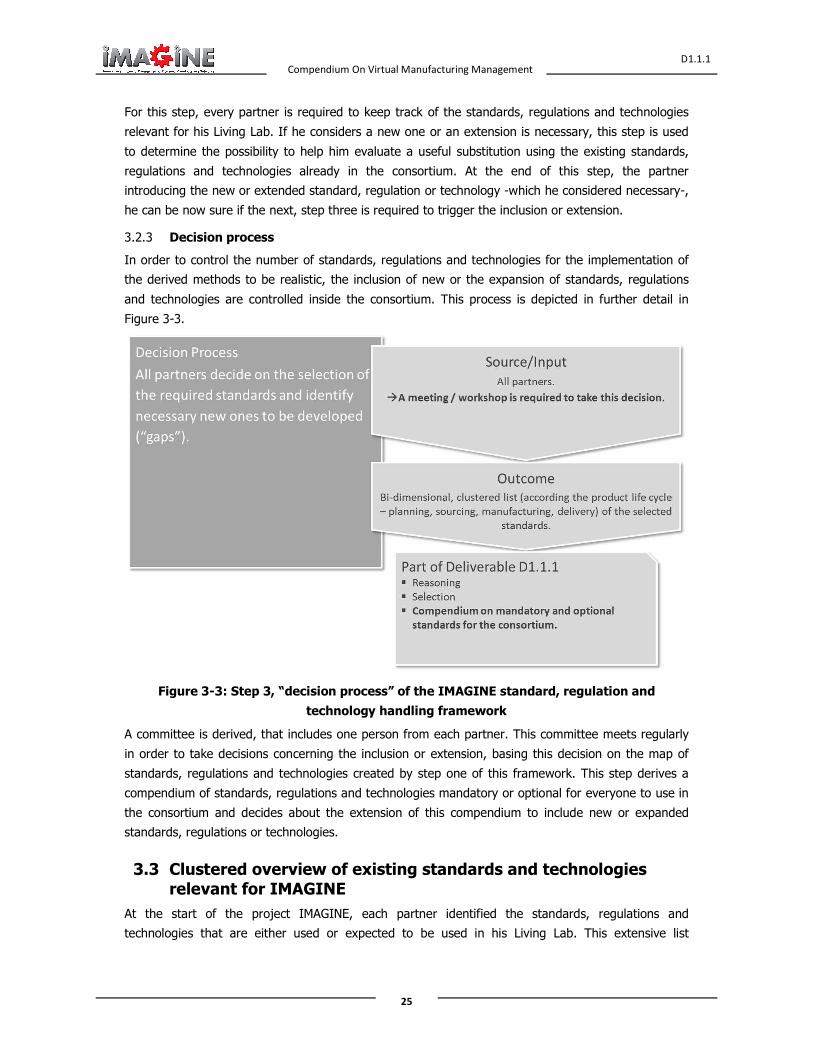
3.2.3 Decision process
In order to control the number of standards, regulations and technologies for the implementation of
the derived methods to be realistic, the inclusion of new or the expansion of standards, regulations
and technologies are controlled inside the consortium. This process is depicted in further detail in
Figure 3-3.
Figure 3-3: Step 3, “decision process” of the IMAGINE standard, regulation and
technology handling framework
A committee is derived, that includes one person from each partner. This committee meets regularly
in order to take decisions concerning the inclusion or extension, basing this decision on the map of
standards, regulations and technologies created by step one of this framework. This step derives a
compendium of standards, regulations and technologies mandatory or optional for everyone to use in
the consortium and decides about the extension of this compendium to include new or expanded
standards, regulations or technologies.
3.3 Clustered overview of existing standards and technologies relevant for IMAGINE
At the start of the project IMAGINE, each partner identified the standards, regulations and
technologies that are either used or expected to be used in his Living Lab. This extensive list

Compendium On Virtual Manufacturing Management
D1.1.1
26
comprises standards, regulations and technologies both from the mechanical engineering as well as
from the IT field.
3.3.1 Standards, regulations and technologies relevant for IMAGINE
In order to enable the consortium to have a common basis of standards, regulations and technologies
in use by everyone, the consortium is asked to list the ones, relevant for IMAGINE in their specific
Living Lab. In sum, more than only standards, regulations and technologies were gathered, in order
to ensure the compatibility of the created IMAGINE platform for all Living Labs:
• Standards: Of course, the standards need to be gathered as most Laboratories are bound to
them. If any technology, method or other gathered relevant input is described in an official
standard, it is preferred to include the official standard instead of descriptions of the method
itself.
• Regulations: In some fields of the mechanical engineering especially, regulations are very
common. In difference to the standards, they are mostly not binding and are often more an
understanding of how to approach certain topics.
• Technologies: In order to enable the consortium to be able to use the most modern
technologies in use today and to ensure the compatibility, the used technologies are
gathered.
• Methods: Some Living Labs are using specialized methods, especially in the field of
optimisation. If they are not standardized, they were included in the table in order to
methodically ensure the compatibility.
• Formats: There are formats which are not (yet) standardised, but are very common in certain
fields. These formats might prove very useful in order to provide the consortium a list of
exchange formats where there are already experiences in the consortium.
All partners identified the standards, regulations and technologies currently in use in their Living Lab
or expected to be relevant to IMAGINE. These have been gathered Table 3-1: Overview over the
standards, regulations and technologies, relevant for IMAGINE. This table will be the basis of
discussion in the workshops of the standardisation group in order to identify gaps and decide on
mandatory or optional standards, regulations, technologies etc. Some of them are gathered from
several partners. This does not necessarily mean they are implemented identically for these partners.
Standards especially can be very extensive and as such might be in use differently, when different
sections of the standards are addressed. In order to prevent confusion, all gathered standards,
regulations, technologies, methods and formats are classified according to the DMN lifecycle as well
as the supply chain lifecycle, each described in the DoW of the IMAGINE project and clarified in
Chapter 2. This information is not describing what the standards, regulations, technologies, methods
and formats themselves are able to cover, but rather what the appropriate partner uses (or could
possibly use) these standards, regulations, technologies, methods and formats for. It is therefore
expedient to include some of them several times, if different partners use them to cover different
parts of the supply chain or DMN lifecycle. This may especially be the case for standards, regulation
and technology that encompass extensive fields (e.g. ISA95) and therefore have an extensive range
of appliance.

Compendium On Virtual Manufacturing Management
D1.1.1
27
General information
Supply chain
lifecycle DMN lifecycle
Phase
Type Name Standardisation body Field
Intro.
Partner Planning
Sourcing
Manufacturing
Configure
Design
Monitor and Govern
Method 5s - Eng. UoW X X X
Method 6 Sigma - Eng. UoW X X X
Method 8D - Eng. UoW X X X
Technology
Advanced
visualization
on the Web
W3C IT EADS X X X X X X
Standard ANSI/ISA95
International
Society of
Automation
Eng. FhG-
IPA X X
Standard ANSI/ISA95
International
Society of
Automation
Eng. FhG-
IPA X X
Standard AS 9100
European
Association of
Aerospace
Industries
Eng. UoW X X X X X X
Format AutomationML AutomationML Eng./IT FhG-
IPA X X X X X X
Standard AutomationML
Deutsche
Kommission für
Elektrotechnik
Elektronik
Informationstechnik
Eng. UoP X X X X X
Standard AutomationML
Deutsche
Kommission für
Elektrotechnik
Elektronik
Informationstechnik
Eng. UoP X X X X X

Compendium On Virtual Manufacturing Management
D1.1.1
28
General information
Supply chain
lifecycle DMN lifecycle
Phase
Type Name Standardisation body Field
Intro.
Partner Planning
Sourcing
Manufacturing
Configure
Design
Monitor and Govern
Format B2MML Eng./IT FhG-
IPA X X X X
Format BPEL Eng./IT FhG-
IPA X X X X X X
Format BPMN OMG IT UoP X X X X X X
Technology BPMN
Object
management
group/Business
process
management
initiative
IT UoP X X X X X X
Technology Caching and
load balancing IT EADS X X X X X X
Format CAEX Eng./IT FhG-
IPA X X X
Technology Cloud-
Manufacturing Eng.
FhG-
IPA X X X
Format COLLADA Eng./IT FhG-
IPA
Technology
Configuration
and change
management
ISO Eng. EADS
Guideline cPlatform
documentation IT LOGO X X X
Standard DIN 8580 German Institute
for Standardization Eng.
FhG-
IPA X X X X X X
Standard Ean 128 LOGO X X X

Compendium On Virtual Manufacturing Management
D1.1.1
29
General information
Supply chain
lifecycle DMN lifecycle
Phase
Type Name Standardisation body Field
Intro.
Partner Planning
Sourcing
Manufacturing
Configure
Design
Monitor and Govern
Standard EDI
National Institute of
Standards and
Technology
LOGO X X X X X X
Guideline
Enterprise
interoperability
framework
EADS Eng./IT EADS X X X X X X
Technology Enterprise
modelling
Open group ISO
OMG IT EADS
Technology
Enterprise
portal
technology
OASIS W3C IT EADS X X X X X X
Technology
Federation
Mashup
Syndication
W3C IT EADS X X X x x x
Method FMEA - Eng. UoW X X
Technology Grid-
Manufacturing Eng.
FhG-
IPA X X X X X
GuideLine GTIP/HS X X X
Standard IDEF0
National Institute of
Standards and
Technology
IT/Eng. UoP X X X X X X
Standard IDEF0
National Institute of
Standards and
Technology
IT/Eng. UoP X X X X
Standard IEC 62264
International
Electrotechnical
Commission
Eng./IT FhG-
IPA X X X X

Compendium On Virtual Manufacturing Management
D1.1.1
30
General information
Supply chain
lifecycle DMN lifecycle
Phase
Type Name Standardisation body Field
Intro.
Partner Planning
Sourcing
Manufacturing
Configure
Design
Monitor and Govern
Technology IMDS HP Eng./IT UoW
Technology
Integration
frameworks
(.Net, J2EE)
IT EADS X X X
Standard ISO 10303
International
Organization for
Standardization
Eng. FhG-
IPA X X X X
Standard
ISO 10303
STandard for
the Exchange
of Product
model data
(STEP)
ISO Eng./IT EADS X X X X X X
Standard ISO 13485
International
Organization for
Standardization
Eng. UoW X X X
Standard ISO 14001
International
Organization for
Standardization
Eng. UoW X X X X X X
Standard ISO 15489
International
Organization for
Standardization
IT UoW X X X X X X
Standard ISO 16739 Industry
Foundation Classes Eng.
FhG-
IPA X X X X X X
Standard ISO 17025
International
Organization for
Standardization
Eng. UoW X X X X X X
Standard ISO 27001 International IT UoW X X X

Compendium On Virtual Manufacturing Management
D1.1.1
31
General information
Supply chain
lifecycle DMN lifecycle
Phase
Type Name Standardisation body Field
Intro.
Partner Planning
Sourcing
Manufacturing
Configure
Design
Monitor and Govern
Organization for
Standardization
Standard ISO 9000
International
Organization for
Standardization
Eng. FhG-
IPA X X X X X X
Standard ISO 9000
International
Organization for
Standardization
Eng. LOGO X X X X X X
Standard ISO 9001
International
Organization for
Standardization
Eng. UoW X X X X X
Standard ISO/IEC
20000
International
Organization for
Standardization
/International
Electrotechnical
Commission
IT FhG-
IPA X X
Standard ISO/IEC
27001
International
Organization for
Standardization
/International
Electrotechnical
Commission
IT FhG-
IPA X X X
Standard ISO/TS 16949
International
Automotive Task
Force
Eng. UoW X X X
Standard ITIL Office of
Government IT UoW

Compendium On Virtual Manufacturing Management
D1.1.1
32
General information
Supply chain
lifecycle DMN lifecycle
Phase
Type Name Standardisation body Field
Intro.
Partner Planning
Sourcing
Manufacturing
Configure
Design
Monitor and Govern
Commerce
Format JT Eng./IT FhG-
IPA X
Standard
Model Driven
Architecture
(MDA)
OMG Eng./IT EADS X X X
Format OWL OMG Eng./IT FhG-
IPA X X X
Format PLCopenXML Eng./IT FhG-
IPA X
Technology
Product
lifecycle
management
ISO Eng. EADS X
Standard
Security
assertion
markup
language
(SAML)
OASIS IT EADS X X X X X X
Technology Semantic
cartography IT EADS X X X X X X
Technology Semantic Web
technology W3C OASIS IT EADS X X X X X X
Technology
Single sign on
and federation
of identity
IT EADS X X X X X X
Technology SOA
Technology W3C OASIS OMG IT EADS

Compendium On Virtual Manufacturing Management
D1.1.1
33
General information
Supply chain
lifecycle DMN lifecycle
Phase
Type Name Standardisation body Field
Intro.
Partner Planning
Sourcing
Manufacturing
Configure
Design
Monitor and Govern
Standard
Software &
Systems
Process
Engineering
Metamodel
specification
Version 2.0
(SPEM2)
OMG Eng./IT EADS X X X X X X
Guideline
SOSI (system
of systems
interoperability
)
Eng./IT EADS X X X X X X
Method SPC - Eng. UoW X X X
Technology System
engineering INCOSE ISO Eng. EADS X X X X X X
Format UBL Eng./IT LOGO X X X X X X
Guideline VDI 2209 Association of
German Engineers Eng.
FhG-
IPA X
Guideline VDI 3633 Association of
German Engineers Eng.
FhG-
IPA X X X
Guideline VDI 4499 Association of
German Engineers Eng.
FhG-
IPA X X X
Guideline VDI 5200 Association of
German Engineers Eng.
FhG-
IPA X X X X X X
Guideline VDI 5600 Association of
German Engineers Eng.
FhG-
IPA X X
Technology WEB server IT EADS X X

Compendium On Virtual Manufacturing Management
D1.1.1
34
General information
Supply chain
lifecycle DMN lifecycle
Phase
Type Name Standardisation body Field
Intro.
Partner Planning
Sourcing
Manufacturing
Configure
Design
Monitor and Govern
Format WSDL W3C IT UoP X X X X X X
Technology WSDL W3C IT UoP X X X X X X
Format XML W3C/OMG Eng./IT FhG-
IPA X X X X X
Format XML Eng./IT LOGO X X X X X
Format XML W3C IT UoP X X X X
Technology XML W3C IT UoP X X X X X X
Standard
XML Process
Definition
Language
version
2(XPDL2)
Wfmc Eng./IT EADS X X X X X X
Format XSD W3C IT UoP X X X X X X
Technology XSD W3C IT UoP X X X X X X
Table 3-1: Overview over the standards, regulations and technologies, relevant for
IMAGINE
At the start of the project, the partners have identified 61 different standards, regulations and
technologies relevant for IMAGINE. As this list is quite extensive and not an appropriate basis for
discussion, it is further clustered in the following chapter.
3.3.2 Clustering of the standards, regulations and technologies
In order to enable the consortium to identify the gaps in the existing standards, regulations and
technologies, the relevant standards have been clustered into a map (Figure 3-4). The categorization
in this figure has been done by type while the sorting of the previous table has been done by the
name of the standard, regulation or standard. It has to be noted, the formats are included as a
subsection of the standards, as most of them are in use in a similar way.
The map will be updated according to the standards, regulations and technologies that will be further
identified during the course of the project. It is the basis for the identification of possible gaps and

Compendium On Virtual Manufacturing Management
D1.1.1
35
will be used for the discussion of standards to be extended or derived by the IMAGINE project.
Standards will be evaluated in more detail for deliverables D1.2 and D2.2.
Figure 3-4: Map of the standards, regulations and technologies relevant for the IMAGINE
project

Compendium On Virtual Manufacturing Management
D1.1.1
36
3.4 Conclusions and Future Work
The standards, regulations and technologies relevant to the IMAGINE project have been identified
and clustered. The listing and clustering of the standards could be subject to change as new
standards could emerge and others standards could be overshadowed by future findings, as it is also
discussed in Section 3.2.
This chapter will be used as a framework to ensure the compatibility of all partners involved in the
planning process. A framework based on the use of existing information standards and reference
models for the information needed in DMN management has been presented in this chapter. The
framework includes standards regarding information, information exchange standards and
standardization bodies related to the ICT tools commonly used during all product development
phases. It describes how the consortium will create mandatory and optional lists of standards already
available and identify -in several workshops over the course of the project- what gaps exist and need
to be addressed by creating appropriate new standards, regulations or technologies or extending
existing ones.
The framework has been completed by taking into account the standards used by industrial partners
systems as well as the latest scientific advances.
The framework has been established on a new approach to standards use and standards
development for the needs of the novel DMN management and provides a strong foundation for the
standards-based integration of the IMAGINE platform with the participating production systems in the
Living Labs in WP4.
In the course of WP2, the IMAGINE platform will be specified. During the course of this work the list
of standards, regulations, technologies, methods and formats will serve as a base of existing
experience when deciding the development of the IMAGINE platform. The selection of standards,
regulations, technologies, methods and formats by the committee as described in Section 3.2.3, will
be based on the requirements of the IMAGINE platform as they arise during the specification in WP2.

Compendium On Virtual Manufacturing Management
D1.1.1
37
4 Living Labs Case Studies Discussion
4.1 Introduction
The IMAGINE Living Labs have been initially defined in this chapter. The main difficulties experienced
have been identified and the initial expectations from the IMAGINE project results are indicated. This
chapter aims to provide the first basic input and to support the detailed definition of the IMAGINE
Platform use cases in Workpackage 2 and the eventual implementation and demonstration of the
Living Labs in Workpackage 4. The IMAGINE case studies are discussed following the same structure
for each Living Lab. Initially, the main objectives are indicated. The current practices are provided
and the existing problems are described. Additionally, the process flow depending on each case under
study is presented. Finally, the expectations from the IMAGINE Platform are discussed and related
business use cases are defined.
4.2 Aerospace and Defence Industry
4.2.1 Objective:
The objective of this Living Lab is the collaborative digital product development within extended
enterprise and networked organizations.
4.2.2 Current Practice and Existing Problems
Currently, the new trends are leading to a full reconfiguration of the Supply Chains within European
Aeronautic and Defence, for various families of Products as illustrated by the following figure.
Figure 4-1: Large family of European Aerospace & Defence Products

Compendium On Virtual Manufacturing Management
D1.1.1
38
New projects are reaching a high level of subcontracting (e.g. 60% for Airbus’ A380) and are
targeting even higher level of subcontracting for future programs (e.g. future long-range Aircrafts
programs are targeting 80%). In addition, it is targeted to reduce the number of tiers-one sub-
contractors, but as these are also sub-contracting a lot, there is a global increase of the number of
sub-contractors for the whole supply chain from level one to the other levels. This trend can be
referred as “Virtualization of the enterprise”. This is illustrated by the following figure which comes
from strategic communication in the area of PLM for Aerospace.
Figure 4-2: Current trends for the Supply Chain for Aerospace
In addition, another trend is the systematic usage of Computer and Modelling for growing set of
Engineer disciplines and for collaboration, leading system usage of Model Based engineering, being
for System Engineering or Product Life Cycle Management. This trend can be referred as
“Virtualization of the Product”.
The combination of both trends is leading to border effects in terms of interoperability for
collaboration within extended enterprise implying interchange and sharing of digital model of the
Product.
In order to respond to such needs, emerging eBusiness PLM Hubs within large groups (EADS PHC
PHUSION) and for the European Aerospace & Defence (c.f. Boost-Aerospace Figure 4-3:
BoostAerospace Hub) are being setup, with on one hand the systematic usage of COTS as
components of the collaborative infrastructure and digital engineering chains, and on the other hand
the identification of strategic importance of eBusiness PLM standards, as promoted by strategic
standardization workgroup such as ASD Strategic Standardization Group or EADS Strategic
Standardization Committee.
In such a context, some issues exist with the expected qualities of the cross organizational
collaborative platform: interoperability, flexibility, robustness, security or other qualities of the
platforms are to be adapted to support a continuously changing Supply Chain without endangering
the Programs. It also appears that appropriate Methodologies and Requirement Engineering for
setting-up such platforms are not available yet, and that on boarding process is facing heterogeneous

Compendium On Virtual Manufacturing Management
D1.1.1
39
maturity of the members of the Supply Chain when dealing with digital collaboration. Finally,
organizational impacts of the strategy used in terms of Architecture, Security and Product Data
Management are not always well assessed by involved organizations and stakeholders because of the
complexity of these new environments and because of the lack of experience in deploying proposed
approaches at this scale.
Figure 4-3: BoostAerospace Hub
In order to illustrate such situation with a concrete example, let’s consider that the A380 program
was delayed due to heterogeneity of the PLM tools used inside Airbus, with important economical
impact. EADS PHENIX (PLM Harmonization) project was launched in order to face such a problem. In
addition, EADS decided to be involved in Boost-Aerospace in order such harmonization also made
inside the whole supply chain, and in order to avoid the digital break between huge OEMs, first level
sub-contractor and SMEs, and in order to face border effect of virtualization of the enterprises. It
should be stated that specifications and Implementation of current hubs are really slow, and on
boarding process could be difficult as such approaches are emerging. On boarding process is
important, and the maturity of the community has to be developed as fast as possible.
4.2.3 Process flow
So the process that is considered is the related to collaborative platform. Such a platform is dedicated
to a digital eBusiness ecosystem (in our case Aerospace and Defence Industry within the area of
PLM), willing to support networked Product Development within Virtual Enterprise.
The process associated to such a platform was defined in ATHENA (FP6 IST-507849) for Network
Product Development platform:
P1- Set up of the platform (Design, development, deployment and enactment)
P2- Interconnection between Information system of a company and the collaborative platform
P3- Collaborating (several instances of collaboration processes)

Compendium On Virtual Manufacturing Management
D1.1.1
40
P4 – Leaving the community (disconnection from the Collaborating platform
Here, it will be necessary for the operator of such a platform to be able to qualify:
• The network of organizations interconnected to the platform in order to support collaborative
product development of digital product
• The network of applications that have to be interconnected in order to support cross-
organizational collaborative processes
Qualification should be done related to different purpose:
• Effective interchange and sharing of product data between partners and CAD/Product Data
Management systems involved (constituting what is called the “digital factory”).
• Secured collaboration
• Maturity in terms of collaboration processes, in particular in PLM and System Engineering
context
• Maturity in terms of interoperability of application for secured collaboration – in link with
relevant standards elected by a Digital Business ecosystem (e.g. European Aerospace and
Defence).
4.2.4 Expectation from Imagine Platform:
The expectation from the Imagine Platform is to provide
• Open, robust and evolutionary environment allowing to aggregate solution components
provided by IMAGINE partners and interconnection with most of the legacy capabilities.
• Dedicated services, based on blueprints and dynamic network management, for the different
stakeholders, such as collaborative platform operators (e.g. THALES for BoostAerospace) and
OEM to be able to qualify interconnected companies and supply chain, all along the life cycle
of the collaboration within a continuous evolving environment.
Usage of blueprints should respond to identified issues such as:
o Appropriate Collaborative eBusiness PLM and Engineering platform set-up within
European Aerospace & Defence ecosystem, aligned with the Manufacturing
ecosystem
o On Boarding process and assessment/monitoring of the maturity of the Supply Chain
Members in terms of digital collaboration and in terms of effective infrastructures
and capabilities
o Collaboration monitoring
o Applicative functional chain monitoring
• Dedicated services for supporting stakeholders, such as ICT departments dealing with Technical Information Systems, Design offices dealing with methods and standard experts within the field of secured Product Data Exchange. Usage of Dynamic Networked Management should in particular respond to identified needs such as:
– Appropriate Service Level agreement between
• Supply Chain partners

Compendium On Virtual Manufacturing Management
D1.1.1
41
• Applicative components and technical components providing services for the collaboration
– Robustness of the underlying reconfigurable infrastructure (Organizational, Functional, Applicative and ICT)
To be driven by Business needs and virtual lab infrastructure, in order to ensure cohesion of the
activities of the IMAGINE partners, in order to build and prepare interoperability appropriately and in
order to accelerate innovation and to respond to Business needs in terms of collaboration within the
Supply Chain. In particular, it is expected that IMAGINE platform could rely on existing experimental
cPlatform defined by EADS IW on the basis of an Interoperability Framework, in order not to reinvent
the wheel, and in order to prepare and construct efficiently and effectively the interoperability within
the IMAGINE project first, and within the targeted communities second (Aerospace but also
automotive, furniture, etc).
As the targeted system is a complex system of systems, some focus should be put on precise
components or aspects, leading to different business cases that will be extended and refined all along
the IMAGINE project. The business cases are listed in the next section.
4.2.5 Business Use Case
Table 4-1: Aerospace Living Lab Business Case index
Business Case Business Case Name Reference
Aerospace_BC1 Digital Business Ecosystem with a set of common standards for
PLM
EADS PHC (PLM
harmonization)
Aerospace_BC2 Product data exchange, sharing and archiving manufacturing
standards elected by ASD Strategic Standardization Group
ASD SSG
Business cases
Aerospace_BC3 Networked Collaborative Product Development ATHENA [DB43]
Aerospace_BC4 PLM collaboration SEINE project
Aerospace_BC5 Functional modeling (SysML) within a SLM context (Simulation
Lifecycle Management)
OpenDevFactory
Project
Aerospace_BC6 Secured collaboration infrastructure for development of the Digital
Behavioural Aircraft within integrated and extended enterprise
CRESCENDO
Aerospace_BC7 Selection of the good components, good standards for the
CPlatform
The listed business cases were to some extent defined in previous research or operational projects which should take advantage of new solutions that IMAGINE aims to define. Several other potential and relevant business cases will be investigated related to other research activities inside EADS
IW/SE.

Compendium On Virtual Manufacturing Management
D1.1.1
42
Other relevant Business Cases will be search within publicly available result of external European projects of interest for EADS IW.
Aerospace_BC1: Digital Business Ecosystem with a set of common standards for PLM
As is situation Stakeholders: Strategic standardization group (EADS SSC), EADS Business Units, their methods and ICT departments, Software product providers, standardization bodies and projects, EADS PHC project, EADS BUs’ partners and supply chains Objectives: To be able to implement effectively a roadmap for PLM harmonization within the EADS group Processes: To identify and elect relevant common methods, services and tools Targeted improvement: To accelerate on boarding process
To be situation Problem to be addressed: To assess simultaneous PLM maturity and global harmonization Generic solution:
• Blueprint for development, implementation and usage of PLM capabilities of PHC
• Collaborative experimental place for acceleration of specifications assessment, maturity of tools, validation of associated collaborative processes and feedback to methods and tools improvement
Specific solution: To be proposed by the partners Assessment criteria:
• Technical level: Robustness, performance, should be easy to use • Applicative/process level:
– Quality of the developed services, tools and associated development process, better interaction between the stakeholders
– Automatic generation and tuning of application interfaces • Organizational level: Usability for the different concerned decision makers
and operational people
Aerospace_BC2: Product data exchange, sharing and archiving manufacturing
standards elected by ASD Strategic Standardization Group
As is situation Stakeholders: Strategic standardization group (ASD SSG), Enterprises in Aerospace domain, their methods and ICT departments, Software product providers, standardization bodies and projects, PLM hubs Objectives: To be able to implement effectively a roadmap for standardization policies for the whole digital business ecosystem Processes: To identify and elect relevant standards, to support policies establishment and implementation by companies and tools Targeted improvement: To establish and measure maturity of the digital ecosystem member for collaboration through digital hubs
To be situation Problem to be addressed: To assess simultaneous usage of standards, related implementations and concerned processes despite number of actors implied for development, implementation and usage of standards Generic solution:
• Blueprint for development, implementation and usage of standards for digital eBusiness PLM standards
• Collaborative experimental place for fasten standard assessment, maturity of interfaces of tools, validation of associated collaborative processes and feedback to standards for improvement
Specific solution: To be proposed by the partners Assessment criteria:
• Technical level: Robustness, performance; should be easy to use

Compendium On Virtual Manufacturing Management
D1.1.1
43
• Applicative/process level: Quality of the developed standards and associated development process, better interaction between users and standardization community; automatic generation and tuning of application interfaces
• Organizational level: Usability for the different concerned decision makers
Aerospace_BC3: Networked collaborative Product Development
As is situation Stakeholders: Programs, Methods&Tools, ICT department, ICT integrators, Objectives: To be able to define easily collaborative space between functional and organizational boundaries at an acceptable price Processes: To define collaborative space, to set it up, to connect, to collaborate to disconnect Targeted improvement: To include new horizontal services for Networked collaboration, for Dynamic Networked Management, as the environment is continuously changing Reference: ATHENA As is and To be scenarios
To be situation Problem to be addressed: To be able to aggregate easily Networked Product Development Collaborative Platform and new kind of services for Dynamic Network Management, with minimum integration effort Generic solution: Interoperability framework, blueprint Specific solution: To be proposed by Imagine partners Assessment criteria:
• Technical level: Reduction of time to deployment – and other resources- for enactment for new service – with appropriate integration/aggregation
• Applicative/process level: Agility and fast adaptation to process and capabilities evolution
• Organizational level: Better robustness for digital collaboration infrastructures
Aerospace_BC4 : PLM collaboration
As is situation Stakeholders: Different industrial sector and domains that can be involved in a given program using PLM standards Objectives: To be able to defined common standards and practices for the industry which need PLM eBusiness standards for similar problems Processes: Multi-domain projects, networking, sharing experience, etc Targeted improvement: Manage the complexity, sharing roadmap and know Reference: SEINE project web site
To be situation Problems to be addressed:
• Providing Common blueprint based on implementation of standards (Methods & Tools)
• Semantic preservation and global coherency of distributed Product Metadata
• Qualification of the federated Interconnected Information systems within the Supply Chain
Generic solution:
• Dynamic Network Management facilities • Shared knowledge base and model of reference repositories for
qualification • Data aggregation • Data transposition
Specific solution:
• Extended hypermodel services (EADS IW) • To be proposed by Imagine partners
Assessment criteria:

Compendium On Virtual Manufacturing Management
D1.1.1
44
• Technical level: Easy collection and federation of data • Applicative/process level: Fast collection and easy maintenance of the
knowledge base • Organizational/level: Easily find relevant information to help decision
making
Aerospace_BC5: Functional modeling (SysML) within a SLM context (Simulation
Lifecycle Management)
As is situation Stakeholders: Design office, method and tools Objectives: To define new methods in order to deal with Digital Behavioral Aircraft, taking advantage of Simulation tools and Simulation Life Cycle Management Processes: Selection of best in class tools for each company, creation of specific SLM systems, integration a posteriori with the partners within the supply chain, high cost for connection with other PLM tools and maintenance of the interfaces Targeted improvement: To prepare and build interoperability at the earlier stage, between partners Reference: Open Dev Factory, Crescendo Enterprise Collaboration
To be situation Problem to be addressed:
• Accelerate elaboration of standards , associated recommended practice by taking into account legacy solutions, and relying on legacy Dynamic Networked Management capabilities developed by other functions of the enterprises
• Adaptation of the quality of service and service level agreement to support digital simulation within networked organizations
Generic solution: To be proposed by IMAGINE partners Specific solution: To be proposed by IMAGINE partners Assessment criteria:
• Technical level: Reduction of the development phase • Applicative/process level: Faster composition and reconfiguration of the
applicative chain • Organizational/level: Reduction of resources required for establishment of
collaboration
Aerospace_BC6 : Secured collaboration infrastructure for development of the Digital
Behavioral Aircraft within integrated and extended enterprise
As is situation Stakeholders: Security officers, Partners in competition, standardization, solution providers, integrator, IT department, Design office, programs Objectives: Secured and effective digital collaboration Processes: Same than for collaborative platform with special focus on interoperability Targeted improvement: To facilitate security requirements and assessment of chosen policies and standards in terms of workability and interoperability Reference: Crescendo secured collaboration platform, Boost-Aerospace, PHC Phusion
To be situation Problem to be addressed: To be able at an earlier phase to specify security requirements and to validate them on the basis of experimentation & To be able to create testbed for security components in order to validate interoperability, robustness, quality of services and price of their maintenance within an evolutionary context Generic solution:
• SCM Networks monitoring • Auto-adaptation • Appropriate level of SLA

Compendium On Virtual Manufacturing Management
D1.1.1
45
• Interoperability Framework Specific solution:
• LAAS: SLA framework adaptation to cPlatform that will constitute the infrastructure of the Aerospace Lab
• Other IMAGINE partners to make proposals Assessment criteria:
• Technical level: Selection, deployment and monitoring of appropriate software components for security – and appropriate tuning for appropriate quality of service and operational maintenance
• Applicative/process level: Percentage of operational time • Organizational/level: Reduction of time for connection to cPlatform for
appropriate secured collaboration
Aerospace_BC7: Selection of the good components, good standards for the CPlatform
As is situation Stakeholders: EADS IW, standardization bodies, research projects Objectives: to develop innovative framework and associated experimental environment supporting fast establishment of eBusiness PLM collaboration based on Computer Aided Engineering with extended and virtual enterprise Processes: Elaboration of component based infrastructure with continuous functional extension and Targeted improvement: scalability and robustness Reference: BootAerospace, PHC Phusion, EADS programs (in terms of amount of data and simulation of number of users)
To be situation Problem to be addressed: How to ensure that collaborative platforms architecture is scalable? Generic solution:
• Coupling of caching, load balancing, adaptive service bus • Blueprint for scalable networked organizations and applications in the
Supply Chain • Monitoring and auto-adaptation
Specific solution:
• LAAS will adapt research on low level network and service auto-adaptation to an Enterprise Service Bus
• Other IMAGINE partners to make proposal Assessment criteria:
• Technical level: QoS for ICT infrastructure • Applicative/process level: OoS for business services • Organizational/level: Amount of resource required for obtaining and
maintaining scalable infrastructure

Compendium On Virtual Manufacturing Management
D1.1.1
46
4.3 Industry agnostic, Multi-site, Single Factory Context
Holistic and multi-scale product design, factory and process planning is a key factor to face the
challenges that are created by shorter product life cycles, increasing number of variants and the need
for an efficient integration of new technologies. The “Grid Engineering for Manufacturing Laboratory
2.0” (GEMLab 2.0) is the Fraunhofer IPA unique platform which provides suitable enabling
technologies to meet those challenges. It is an innovative workflow-and grid-based planning
environment, integrating self-developed and state-of-the-art commercial tools, for continuously
integrated product design, factory and process planning along the whole factory life cycle [27]. It
enables the collaborative sharing of resources and competences in engineering of factories and
products and supports the integrated and continuous management of the entire Product and Factory
Life Cycle [20].
Figure 4-4: Continuously integrated factory engineering and design
The innovative GEMLab 2.0 is an industry-agnostic, multi-site factory and process planning
environment. It is characterised by the employment of innovative solutions and integrated state-of-
the-art digital manufacturing tools. In sum, those properties enhance the quality, reduce the time and
optimise the planning of processes, factories and production networks. A Change Propagation System
guarantees the consistent propagation of data changes within the planning environment. This way a
continuous integration of the information flow along the whole the planning process can be achieved.

Compendium On Virtual Manufacturing Management
D1.1.1
47
The GEMLab 2.0 is comprised of current digital tools for planning and engineering of products,
processes and factories. Integrated are two types of digital tools, commercially available (Siemens
Industry Software GmbH & Co. KG; Parametric Technology GmbH) and in-house developed systems
(Fraunhofer IPA). There is a plethora of hardware and software available, of which a complete
overview is given in the next figure.
Hardware
1. GEMLab, FhG IPA
Stereoscopic 3D-Projektion-Wall8
• 10 dedicated PC Workstations• 12 High-End-PCs for 3D-Cube System• 14 further PCs as additional
Workstations
Cooperative Planning Table
VR-Systems:� SpaceMouse� Nintendo Wii Control and Balance Board
2. Smart Factory IFF Uni Stgt.
Ubisense, different mobile terminals, RFID readers
3. Parts of IFF Learning Factory IFF Uni Stgt.
Physical Learning Factory and coupled Digital Learning Island
Software
Planning Phase Tools
Product development NX3, Pro/Engineer4, AutoCAD10, Inventor10
Product life cycle management Windchill4
Investment and performance planning FLIP1
Site and network planning vProNet1
Process, equipment and workplace planning
Process Designer / Process Simulate3
Process simulation Plant Simulation3
Layout planning Cooperative Planning Table1, Process Designer3, FactoryCAD3, SBFP9
Internal logistics FactoryCAD3, FactoryFlow3, Plant Simulation3, Order Management System1,2
3D visualization GEM Factory Immersion1
Factory operation Failure Management System1,5
Order Management System1,2
Factory Cockpit1,2, DataEngine1,2
ProVis.Agent7, ProVis.APS7, ProVis.Visu7
Total Energy Efficiency Management1
Factory life cycle management Teamcenter Manufacturing3
Planning workflowSystem integration
GEMFlow (workflow system)1
Globus Toolkit6
1) Fraunhofer IPA2) IFF Universität Stuttgart3) Siemens Industry Software4) Parametric Technology
Corporation (PTC)5) Sikom Solvtec
6) GlobusAlliance7) Fraunhofer IOSB8) Eyevis9) University of Malta10)Autodesk
Figure 4-5: Hard- and software infrastructure of GEMLab 2.0
4.3.1 Objective
The objective of this case study is to enhance the state-of-the-art industry agnostic living lab called
“GEMLab 2.0”, which is very well suited for factory level planning and optimisation, in order to enable
the planning and optimisation of Dynamic Manufacturing Networks. Thus, an optimal factory and
network planning and optimisation, considering stakeholders and dynamic changes in a production
network can be achieved (Figure 4-6).
Figure 4-6: Use case scenario – Objectives

Compendium On Virtual Manufacturing Management
D1.1.1
48
The main goals, which will be addressed in the use-case scenario, are:
- Reduction of effort for planning factories and manufacturing networks
- Consideration of dynamic changes in a manufacturing network
- Value added ideal dynamic manufacturing network planning
- Agile planning processes to handle order and engineering changes.
To achieve the overall objective, new methods and reference models have to be developed and
integrated in the industry agnostic living lab. Thereby different aspects have to be considered:
- The enhancement of existing factory planning reference models, concerning rules and processes within manufacturing networks
- The development of blueprints to characterise supplier, stakeholder, factories and products of a specific manufacturing network
- The development of a method for knowledge-driven multi-scale modelling of existing manufacturing networks
- The development of a method for the optimisation of multi-site, multi supplier, multi-customer networks
- The analysis of specific “What if” scenarios
Thus, the modelling of factories as well as dynamic manufacturing networks and their subsequent
optimisation will be supported through suitable methods and reference models, to ensure the
competitiveness of the participating industry partner in a first step and in a second step for the whole
European industry.
4.3.2 Current Practice and Existing Problems
Factory Planning
State-of-the-art reference models for Process Development and Factory Planning provide defined,
structured and standardized workflows for different factory and process planning activities to over-
come the current challenges in Manufacturing Engineering [26, 27]. The predefined standardized
planning activities improve the communication between planning partners, interdisciplinary teams or
stakeholders, who participate in different phases of a factory planning activity ([27], [28]). The first
factory reference models were proposed as factory structure reference models. These reference
models are targeted to a specific industrial sector or they are very generic and describe the structure
of a factory without taking its life cycle or processes into account [29, 30, 31]. Today’s reference
models for Process Development and Factory Planning provide a various level of detail for each
planning phase and support different phases of the factory life cycle [32, 33]. [34, 35] concentrate
on the factory planning (investment, building, layout, logistics planning and ramp-up) without
considering the manufacturing execution planning and the dismantling of the factory [33, 32, 35, 34,
36]. A more holistic view on the factory planning life cycle is provided by the VDI (Association of
German Engineers) and Westkämper. There, the factory life cycle phase “manufacturing execution” is
additionally taken into account ([27], [28]). However, the dismantling is not considered in those
approaches. [37] provides a factory and process planning reference model, which concentrates on
the factory planning phases up to manufacturing execution in a highly detailed way. An innovative
point in the approach of [37] is that it also takes the relations and interdependencies between the
planning phases into account [37]. The approach of [38] concentrates on the whole factory life cycle
including manufacturing execution and the dismantling of the factory; also the information flow in the
manufacturing execution phase is considered briefly [38]. The VFF (Virtual Factory Framework, EU

Compendium On Virtual Manufacturing Management
D1.1.1
49
Project, available at www.vff-project.eu) reference model for Factory and Process Planning is a
generic, modular, open and extensible reference model taking into account the factory planning
phases from investment planning to ramp-up. Every planning phase is described through detailed,
structured and standardized planning activities. The information flow between the planning phases is
also considered (VFF NMP-4).
The methodology and reference models for Product and Factory Lifecycle Management are
implemented in several existing commercial software applications, on which the table below gives an
overview.
CAx-
App. Description Software Application
PLM
Product Lifecycle Management (PLM) is the process of
managing the entire lifecycle of a product from its
conception, through design and manufacture, to
service and disposal.
Teamcenter-Engineering
Windchill; ENOVIA
FLM
Factory Lifecycle Management (FLM) is the process of
managing the entire life cycle of a Factory from its
conception, through planning and operation, including
maintenance and dismantling.
Teamcenter-
Manufacturing
Table 4-2 Commercial software applications for Product and Factory Lifecycle
Management
[39] focuses on the knowledge-based integration of product development, process planning and the
planning of the production system. At the same time economic instruments are considered. Recently,
the CIRP working group SPECIES (SPECIES) highlighted how critical the modelling, integration and
evolution (named co-evolution) of products, processes and production systems along their life cycles
is. [40] addressed the co-evolution problem both from the industrial and academic point of view, by
presenting industrial use cases and extensively analysing the scientific literature, respectively.
Moreover, the authors presented a reference model to study the integration between products,
process and production system in terms of requirements to face a specific industrial problem,
constraints imposed by the internal and external Factory Environment, and capabilities offered by
methodologies and tools. Finally, [40] identified a collection of future research priorities to be
addressed: need of technical standards for evolving information related to product, process,
production systems; development of co-evolutionary Design-for-X methodologies; new Business
Models for co-evolving product, process and production systems; new production system
architectures to support the changes in products and processes; reconfigurable process plans.
Thus, the state-of-the-art reference models mainly aim at decreasing the complexity of the planning
activities and modelling as well as managing all the necessary information and communication flows.
However, these reference models are not able to integrate the different planning life cycles of the
product, the process and the factory in a knowledge based approach.
Network planning
The ideal distribution of a manufacturer’s production sites is a crucial issue to assure their
competitiveness. An early model which supports the managing of new production capacities in

Compendium On Virtual Manufacturing Management
D1.1.1
50
production networks is developed by [41]. Thereby the production network is divided into two levels,
the production site level and the headquarter level. By dividing the network into these levels, [41]
generated a simulation model to analyse the future changes in the production program. Based on the
research activities of [41], [42] and [43] develop a three level production network model. This
contains the network level, where production sites are chosen, the site level, where the production
program of the single production sites is planned and the production module level, where the detailed
planning of production processes is carried out. Other approaches in the field of network planning
concentrate on mathematical optimisation. [44] developed a method for designing and evaluating
global production networks based on a quantitative analysis of network costs. [45] and [46] focus
more on the aspect of analysing costs at one production site and neglect the extension to production
networks. Another approach pursues the value added ideal production network planning. Thereby the
flexible and cost optimized simulation based distribution of the value creation in a production network
is supported through the employment of a reference method consisting of seven [47].
Today’s network planning approaches consider a high variety of aspects, while developing a model of
a specific production network. However, the following optimisation is mostly based on static factors.
Dynamic changes regarding stakeholder, supplier and factories in a production network are not
considered properly. The knowledge-driven communication between the factory level (product,
process and factory life cycle) and the network level (stakeholders, suppliers), is not supported by
existing reference models, either. This reveals a lack of dynamic change consideration and
knowledge-driven communication between the stakeholders, suppliers and the factory level.
Summary
In summary there are some issues that have to be addressed in this use case scenario to enable a
holistic modelling and optimisation of a production network with its containing stakeholders, suppliers
and factories. These are:
- Integration of the factory level and the network level in on holistic reference model
- Suitable consideration of dynamic changes within a complex Dynamic Manufacturing Network
- Suitable standards for communication and data/information exchange within a complex Dynamic Manufacturing Network
- Adequate optimisation methods for complex Dynamic Manufacturing Network
Thus, this use case scenario will enhance and integrate previously developed reference models, in
order to develop a holistic, knowledge-driven, industry-agnostic reference model, which considers
both, the integrated factory level (product, process and factory life cycle) and the network level
(stakeholders). This concept allows the efficient modelling and simulation-based optimisation of
complex Dynamic Manufacturing Network.
4.3.3 Process Flow
This chapter evaluates the needed process flow for the realisation of the planned use case scenario.
Six steps have to be performed, in order to achieve the defined objects and goals. These steps,
depicted in Figure 4-7, are:
1) The definition of the considered products.
2) The characterisation of the involved supplier.
3) The definition of the structure of the production network.
4) The following analysis of the production structure.

Compendium On Virtual Manufacturing Management
D1.1.1
51
5) The definition of the production site.
6) The definition of the production modules.
Based on this, the ideal involvement of production sites and production modules, the production
networks can be defined. Thus an efficient modelling and value added ideal manufacturing network
optimisation is enabled.
Figure 4-7: Process flow of modelling and optimising a Dynamic Manufacturing Network
Before planning and optimising a DMN, a clear understanding of the strategic goals, which will
eventually determine the formation of the Dynamic Manufacturing Network, has to be defined. To get
a clearer view on these processes, an example, based on an exemplary product, will be given on how
this process can be applied. The exemplary product will be a desk set comprised of two existing
components –a clock and a cup– and a new component –a lamp–. This exemplary product is depicted
in Figure 4-8.
Figure 4-8: Exemplary product – Desk Set
First of all, the adaptation of the existing DMN has to be clarified. Will the lamp be built in an existing
production site or in a new production site? Strategic goals should initially be defined. Based on these
strategic goals, in the first step, the relevant product –the lamp– and its component parts are
identified, keeping the modelling and optimisation of a DMN characterised by blueprints in mind.
These are e.g. the inlay and the body housing. Additionally, involved suppliers, which will supply
specific parts for the lamp, are characterised e.g. regarding their competences to manufacture the
needed parts, their ability to deliver and their cost. Those input parameters, represented by key
performance indicators, requirements and blueprints enable a detailed analysis of the whole existing
production network and its restructuration. Relevant information e.g. transportation or capacity in

Compendium On Virtual Manufacturing Management
D1.1.1
52
different sites, considering the planning and further optimization are identified too. Based on this
identification, performance indicators are defined and used to generate an accurate performance
measurement framework for the following subsequent steps. This framework enables the evaluation
of the production network regarding the ideal involvement of production sites and production
modules in the production network. The result of this step is a rough Dynamic Manufacturing
Network. This rough Dynamic Manufacturing Network shows where the parts of the lamp will be
manufactured and assembled and brought together with the desk set.
Based on the results of the first step, a rough layout of the DMN can be developed, considering the
layers of a factory down to sites, single machines and machine units. This rough DMN layout builds
the basis for a detailed arrangement of machines and equipment using simulation as a basis, to
enable the most efficient manufacturing and assembling of the lamp and the desk set regarding the
material flow, energy efficiency and/or others. Furthermore, the performance of the whole DMN can
be calculated by taking into account the defined performance indicators, requirements and blueprint.
The results of this step are an optimized DMN down to sites, a factory performance forecast and
optimized manufacturing lines to manufacture the whole desk set.
After the planning and optimization of the DMN, in a third step, the customer orders will be provided
or generated – in the case the customer orders for the planned DMN are not identified. Based on
these orders, the production sequence of the lamp and the desk set can be planned and the
manufacturing line can be evaluated using the discrete event simulation as well as the closed loop
simulation. The planning of the production sequence and the evaluation of the different production
lines considering the different sites can be performed. The last step is the consideration of the factory
operation. In this step the real data of the DMN will be used to enable the monitoring of the defined
KPIs. Figure 4-9 shows the described planning phases within this Business Use Case and the different
planning activities.
Figure 4-9: Living Lab method for the modelling and optimisation of a DMN
4.3.4 Expectation from Imagine Platform
The overall expectation of this use case scenario is an industry agnostic, multi-site, single factory
context platform that enables a holistic and efficient modelling and optimisation of complex
production networks. Thereby the evolving issues, which arise from multi-site, multi supplier, multi-

Compendium On Virtual Manufacturing Management
D1.1.1
53
customer networks can be addressed. Not just static optimisation methods can be applied, but
dynamic optimisation methods, which enable a value-added ideal dynamic manufacturing network
planning.
Additionally characteristics and KPI’s to describe supplier, stakeholder, factories and products of a
specific manufacturing network through blueprints, which will be used as valuable and suitable input
for the method developed in this use case scenario, are to be developed for this scenario. This is then
used to verify the proper functionality of the optimisation method and enables the analysis of specific
“What if” scenarios. Thus, the modelling of factories as well as dynamic manufacturing networks
(DMN) and their subsequent optimisation will be supported through suitable methods and reference
models.
4.3.5 Business Use Case
The Business Use Case considering the Industry agnostic, Multi-site, Single Factory Context Living Lab
consists of four different steps for the planning of Dynamic Manufacturing Networks (DMN).
Due to the detailed definition of the Use cases in WP2-Deliverable 2.1, a conceptual overview of
currently practicable Use Cases for the GEMLab 2.0 will be given. These business use cases may
consider a manufacturing engineering enterprise, which has to adapt its production network, because
of different turbulent market influences.
These influences can be addressed by this Business Use Case:
- A Tier 1 supplier is insolvent.
- One or more Tier 1 or 2 suppliers are too expensive to contract them in the future.
- New customer requirements are propagated to the product development and new technologies are needed to fit them.
- The whole production network performance has to be improved by restructuring the existing international production network to increase the own competitiveness.
- A new site has to be built and the production system and layout have to be planned.
- New orders are placed with different requirements concerning focus on quality, price or production time.
- Existing manufacturing layouts have to be optimized.
With the method, described in Section 4.3.3, all these aspects can be addressed. By using blueprints
of different suppliers a supplier can be replaced in a very short time and new suppliers, which meet
the requirements considering the technology for the production an innovative product, can be
identified. Furthermore the performance of an established production network can be evaluated
regarding its product component manufacturing distribution in different sites and its network
production sequence as well as throughput times. Also, new site projects can be evaluated in advance
with the help of simulations.

Compendium On Virtual Manufacturing Management
D1.1.1
54
4.4 Furniture Manufacturing Industry
4.4.1 Objective
Furnishing Living Lab will check the benefits of IMAGINE for the furnishing sector with a main
scenario: on-demand supply and production networks, which is the most commonly used system in
the furniture manufacturing industry and divided in two main fields (supply network and production
estimation).
4.4.2 Current Practice and Existing Problems
It is quite obvious that the whole Furniture Manufacturing Industry does not work in a unique way
and at every level of the supply chain there are companies working with different organization
structures. Anyway it is also true that there is a mainly representative group of companies that share
a common work system.
Therefore we will assume that there is a most common system and in order to describe the current
practice we will use but it is important to state that in this sector, probably the most well known
companies are not the most representative ones (for instance IKEA).
First of all we will show by means of the next diagram an overview of the supply chain, from the first
supplier to the end customer.
Figure 4-10: Furniture Living Lab end-customer

Compendium On Virtual Manufacturing Management
D1.1.1
55
The above figure represents an end customer (any individual who wants to furnish a room) who gets
in a furniture shop (retail) and after watching the showroom, orders a list of items.
Probably this order will be made of items from different manufacturers: for instance the sofa is made
by one, table and chairs by another one and the shelves, and cabinets by another one. Then the
retailer converts this order into several purchase orders to all those manufacturers.
On the other hand, each furniture manufacturer, in order to make these items, will group them with
other orders and plan this manufacturing process. For this group of orders, he will also need to buy
some raw materials or components to his provider.
Then, these materials will be sent to the furniture manufacturer, who at this point will be able to
manufacture the components and assemble them. And once they are packed they will be sent to the
retail warehouse.
When all the required components are at the warehouse, the retailer will call the end customer to
agree a date for the delivery and at-home-assembling.
Involved Roles
In the next section every role is detailed.
End Customer
This role represents any individual who has the intention to furnish a room or a whole house and
visits one or several showrooms to decide what he / she wants.
Retail
In this sector the retailer is commonly represented by furniture shops with a showroom where the
customers can watch some proposals from different manufacturers. These shops may be independent
or part of large chains of shops. Apart from these proposals they have a library of catalogues with all
the possible options for every item and its price because it is impossible to show every product and
every option. These catalogues contain technical information like dimensions, finishing or base
material.
Normally the customer asks for several estimates for different possibilities assessed by the sales
person. At the end he confirms one of them and is converted into a firm order.
Once the order is ready, the retailer converts that order into one or several orders to their suppliers
(furniture manufacturers). They can be several because the list of products of the order can come
from different catalogues from different manufacturers.
These orders are sent by FAX or electronic mail.
From this point, the retailer waits for the reception of the products from every manufacturer and for
this purpose they work with warehouses. Sometimes, the retailer is also the owner of this warehouse
and in other situations, they outsource this process. This process is called orders consolidation.
The last process is the delivery and at-home-assembly. It may be carried on order by order or
grouping several orders when destination is the same.
Furniture manufacturers and suppliers also play an important role in the furniture manufacturing
industry. Their roles are discussed in the next section.

Compendium On Virtual Manufacturing Management
D1.1.1
56
4.4.3 Process Flow
Table 4-3: Software Tool Commonly used in Furniture Industry
ERPs (Company) CAD / CAM 3D Furnishing (Company)
Purpose: insight
management
Purpose: design of
catalogue, parts and
generating manufacturing
instructions
Purpose: Showing (at the
retail) to the customer the look
of a room with the selected
items and generating the order
to the factories.
Gdp (AIDIMA)
Teowin (Simsa)
SPIWood (2020)
expertMueble (Datadec)
Note: commonly well
known ERPs like SAP,
Navision, Axapta, Oracle,
etc are not very popular in
this sector.
Inventor +Alphacam
Autocad (only CAD)
Topsolid (CAD + CAM)
Cabinet vision + Alphacam
S-Planner (AIDIMA)
Teowin (Simsa)
Planit
Profiles for Products
In the furniture industry, we can classify the products according to many different criteria, but in
order to define them for the IMAGINE platform, we must consider a sorting that allows us to define
them in a unique way. With these criteria we find two main kinds of products:
• Furniture. For these products (chairs, tables, cabinets, sofas, etc) there is a specific way to identify them based on a reference and a list of properties. This way solves the problem of the huge amount of features available for every part of every product which combined enables a very wide range of choices for everyone. Then to identify a product we need a data structure like this:
Figure 4-11: Products - Features
• Components. These products are the ones that are required by the furniture manufacturers in order to make their products. They can be identified just by a reference and some additional information. Then in order to identify a product we need a data structure like this:

Compendium On Virtual Manufacturing Management
D1.1.1
57
Figure 4-12: Furniture Products
Profiles for Manufacturers
Furniture Manufacturer
For the furniture manufacturer the process starts when they receive an order from a retailer. They
never sell directly to the end customer but when there are specific situations with family, etc.
Every order is registered as most of them work with some kind of sw. program, at least for the sales
department. There are others, but cannot be considered a standard, that have integrated information
systems like ERPs. Independently of the IT solutions they have implemented, these manufacturers
manage to review and plan the manufacturing process along the different shop floor departments.
Commonly this is made grouping these orders by some criteria according to their needs. Most
common criteria are:
• Geographical delivery area, when they need to optimise transport
• Colours, when they need to optimise the finishing line and they don’t need to optimise transport
• Delivery date, when they must accomplish with this date (this is not often a must)
• Order reception date, when the priority is the lead time
According to these grouping criteria, the manufacturing process starts with the final objective that
orders need to be sent complete.
The furniture manufacturer is not a simple assembler of parts that they buy. They usually
manufacture most of the wood components from the motherboard, if required they polish them and
finally they assemble and pack them.
One of the main difficulties for a manufacturer is to get the required materials on time so that they
can avoid delays in the delivery terms. In order to get this they usually have an oversized warehouse
for the most common materials but for others that are expensive or not very common it becomes a
difficult task. Here we show a list with the typical materials that are supplied to a furniture factory:
• Wooden or melamine Boards
• Edges
• Glue
• Varnish
• Pulls
• Glass parts for different purposes: doors, shelves, etc.
• Several types of iron fittings.
In the next diagram you can observe one of the common production flows:

Compendium On Virtual Manufacturing Management
D1.1.1
58
• Material reception. Normally stored in organised warehouses, not chaotic ones.
• Cutting from board. Standard size boards are bought and the cutting process tries to optimize the waste of board by means of a program that uses an algorithm to achieve it.
• Edge banding. It is the process that adds a nice edge to the cut part.
• Machining. This process can drill or shape the parte to fit the needs. This is the technologically most advanced process and uses CNC programs.
• Polishing. Depending on the type of base material and finishing the parts may be polished. Two main groups: wooden parts are always polished and melamine parts are only lacquered in some cases.
• Assembly. Both manufactured and bought parts are assembled.
• Packing. Every product is packed, using one or several packs.
• Grouping order. As orders need to be sent complete, but they are not made all at a time there is a necessary process to store items while the others are being made. This is usually done by metallic structures with wheels to be moved easily.
Cutting from board
Edge bandingMachining
Polishing
Assembly
Packing
Grouping order
Material reception
Figure 4-13: Furniture Industry Common Production Flow
The manufacturer is also responsible for the transport till the retailer and for this process, different
situations occur:
• Carriers and trucks own to the manufacturing company
• Delivery agencies are outsourced
• Self-employed workers are outsourced to cover specific routes.
Supplier

Compendium On Virtual Manufacturing Management
D1.1.1
59
The supplier plays a very important role in this supply chain because as described above it becomes a
difficult task for the manufacturer to be able to plan what they will need because there is a very wide
range of materials and it makes that some of them have to be ordered on demand.
As the supplier is actually a manufacturer that provides raw materials or components we can assume
that they work with a similar system than described for the furniture manufacturers but, obviously
with different production processes.
4.4.4 Expectation from IMAGINE Platform
From the Furniture Industry Living Lab there is a matching from the user requirements of the furniture scenarios to the three phases of IMAGINE.
In the following figure there is a representation of such matching:
Figure 4-14: Furniture Industry - User Requirements Matching to IMAGINE Phases
1. Phase 1: Configure � Product, services and suppliers definition. This phase will be carried on when a new catalogue is being designed. At this stage it is necessary to design every component and also to find providers for the new materials. Even though commonly providers are normally the same from one catalogue to another, this phase of IMAGINE will be specially interesting to search providers for innovative materials like novel iron fittings, novel types of boards made of lighter panels, etc.
2. Phase 2: Design � Offering/Bidding for new products. After products/services and providers have been defined by means of their respective Blueprints, at this phase the user of IMAGINE will select the most appropriate suppliers within an Offering/Bidding process. In order to help the user in his decision making process, some kind of simulation process may be utilized to show the complete lead times at every situation.
3. Phase 3: Monitor & Govern � Orders management and tracking. Once a product is defined and the required suppliers have been selected, this phase will be focused on the tasks involved in the entire process to produce and serve an order (it is assumed that the MRP process knows the required materials and terms kept at factory level).

Compendium On Virtual Manufacturing Management
D1.1.1
60
4.4.5 Business Use Case
Figure 4-15 shows an overall overview of the Furniture Business Use Cases and the standards and possible services that may be used.
Figure 4-15: Furniture Industry Living Lab business case overview
All the communication between the blueprint and the DMN will be made by XML files, since it is a widely-used format for sharing structured information.
These are the 3 proposed Business Use Cases:
Table 4-4: Furniture Industry Living Lab business index
Business Case
(acronym)
Business Case Name
Furniture_BC1 Configuration of Product, services and suppliers definition
Furniture_BC2 Design by Offering/Bidding for new products
Furniture_BC3 Monitor & Govern: Orders management and tracking

Compendium On Virtual Manufacturing Management
D1.1.1
61
Table 4-5: Furniture Industry Living Lab Business case overview
Furniture_BC1: Configuration of Product, services and suppliers definition
As is situation Stakeholders: Manufacturers, Retailers, Transports. All stakeholders in furniture value chain. ICT department. Objectives: To be able to manufacture a product under any supply service problem.
To be situation Problem to be addressed: To be able to re-configure a product under any supply problem finding a fast supply agent. Generic solution: Interoperability framework. Blueprint for configuration on products, services and suppliers. In the “Configure” phase, which includes the design of the new products, it is necessary to design every component and also to find providers for the new materials. The standard ISO 10303-236 (AP236) will deal with the product data information for the furniture industry, then the ISO 10303-25 is needed to specify the mappings between the EXPRESS data specification language into the Object Management Group’s (OMG) Unified Modelling Language (UML). It will be necessary:
• Specification for every product to manufacture. This specification should include information not only about the end product, but also for every part of it: dimensions, machining, finishing, etc. The intention is to make use of the ISO 10303-236 standard which deals with the product data information for the furniture industry. Furthermore, it has to consider a multi-attribute management, which is a specific requirement at this industry (for example any cabinet has different choices meaning colours, knobs; in a sofa the choices are mainly the textiles which combined generate a very wide range of options for it).
• Specification for every purchasing component. These components may be standard or innovative. In the first case, just a reference would be necessary but in the second one, it would be necessary to attach some technical (probably CAD/CAM) files to define them. Products will be defined using some kind of multi-layered categories, so that they can be
structured. Some typical examples for this purpose could be transportation or polishing which are usually subcontracted.
• Specification for every required service. For this definition, it will be used technical information by means of technical files. Services will be defined using some kind of multi-layered categories, so that they can be structured. Some typical examples for this purpose could be transportation or polishing which are usually subcontracted.
• Specification for every provider in order to ease the search of providers some kind of multi-layered categories will be used (the same one than for services and components). In this way it will be possible to find providers at the next phase
Specific solution: To be proposed by the partners Assessment criteria:
• Technical level: Very easy to use by SMEs • Applicative/process level: Quality of the developed services for a better

Compendium On Virtual Manufacturing Management
D1.1.1
62
product configuration between the stakeholders • Organizational level: Usability for the different concerned decision makers
Furniture_BC2: Design by Offering/Bidding for new products
As is situation Stakeholders: Manufacturers, Retailers, Transports, all stakeholders in furniture value chain. Objectives: Find new providers in other value chains for new product manufacturing.
To be situation Problem to be addressed: to be able to bid/offer the manufacturing of a new product to new suppliers. Generic solution: Interoperability framework. Blueprint for provider seeking to offer a bid for manufacturing a new product. In the “Design” phase, there is the same issue regarding the product data information, so both AP236 and the ISO 10303-25 will be used in the blueprints definitions. The ebfSOA is responsible of the documentation of the blueprints, in particular the documentation related to the administrative and commercial tasks (RFQs, Invoices, etc.) . The JADE is a Multi-Agent Systems (MAS) that will be responsible for searching new suppliers, as JADE enables the creation of a short list of suppliers that have the raw materials available, making the search faster. From the point of view of a company which has developed a new product:
• Sending information by the DMN to the suppliers whose blueprint matches the product definition so they can bid for providing it.
• Sending information by the DMN to the suppliers whose blueprint matches the service definition so they can bid for providing it.
• Receiving information from the potential suppliers about the terms of service: lead time, terms of payment, price.
• Selecting suppliers for those products or services at a test-mode. • Simulating the whole process according to the information received. This
simulation must provide information about:
- Complete lead time
- Total cost
- Terms of service.
• Selecting suppliers for those products or services and sending them a confirmation
From the point of view of those suppliers:
• Receiving information about the requirements of the products or services • Sending their bids with:
- Prices
- the appropriated SLAs (Service Level Agreements)
- Lead time
• Joining “the consortium” once they have been confirmed
Specific solution: To be proposed by the partners Assessment criteria:
• Technical level: Robustness, performance; easy to use for SMEs • Applicative/process level: Quality on selecting and searching new possible
providers • Organizational level: Usability for the different concerned decision makers

Compendium On Virtual Manufacturing Management
D1.1.1
63
Furniture_BC3: Monitor & Govern: Orders management and tracking
As is situation Stakeholders: Manufacturers, Retailers, Transport,… All stakeholders in furniture value chain, ICT department. Objectives: To know the situation of any order at manufacturing level as well as at delivery level.
To be situation Problem to be addressed: To be able to monitor any order traceability. Generic solution: Interoperability framework (ebfSOA), blueprint for order tracking for:
• Sending to the DMN the Bill of Materials and services required from the orders. Some kind of automatic process should redirect every order to its previously selected supplier.
• Sending / receiving confirmation of the reception of the order and the lead time.
• Tracking at any moment the status, not only of an order of a component, but also of the whole process to achieve the actual target: serving on time the whole order, i.e. comparing the estimated shipping terms with actual date and having the option to see how a delay affects the whole process.
• Tracking the delivery status of the order once it has been sent
The “Monitor & Govern” phase uses ebfSOA once again for all the documentation pertaining to orders, tracking the delivery and order status. Also, here in this phase, JADE may be utilized to help in the monitoring of the documents, to search for changes and warn the user. Specific solution: To be proposed by Imagine partners Assessment criteria
• Technical level: Robustness, performance; easy to use for SMEs • Applicative/process level: Quality on finding and searching an order • Organizational level: Usability for the different concerned decision makers

Compendium On Virtual Manufacturing Management
D1.1.1
64
4.5 Car Manufacturing Industry
The Car Manufacturing Industry Living Lab is a replicated automotive production network reproducing
in test environment the actual layout of a manufacturing chain along its main lifecycle phases with a
detailed focus on inbound flows and spare parts management.
4.5.1 Objective
The objective of this Living Lab is the collaborative digital product execution to ensure business
continuity in large organizations.
4.5.2 Current Practice and Existing Problems
Current practices
The automotive production network includes the OEM plant and its main part suppliers. In the Living
Lab, order, manufacturing and provisioning of parts are performed, towards the OEM plant (inbound
use case) and to the spare part dealers (spare parts use case), as displayed in the Figure 4-16 below.
Figure 4-16: Automotive production network
On top of that, many other users are involved, such as:
• global supply chain management, for the design and coordination of the network; • procurement and material management, for the identification of suppliers, contracting and
execution phases
• production planning and warehouse management, at the plants level • spare part and car dealers, which can be independent from the OEM
The ERP (Enterprise Resource Planning) system implements all the order management for incoming
parts and connects to the MRP (Manufacturing Requirements/Resource Planning), the MES
(Manufacturing Execution System) and the Click WM for the management of inbound/spare parts.

Compendium On Virtual Manufacturing Management
D1.1.1
65
Click WM is the dedicated system which provides visibility on the level of stock in the warehouses, as
shown in Figure 4-18. All systems are interfaced one each other throughout the supply chain.
The suppliers are involved through a collaboration portal that will be simulated by using a
customizable social networking platform for B2B called TamTamy. This platform is already in use by
FIAT Group companies for interacting among dealers and manufacturing.
The customization will enable, through usage of APIs, to post a request to the suppliers’ community
in real time, manage a bid among them based on response parameters (time, cost, quality, shipping
terms etc.) and drop an order.
The suppliers subscribe to the collaboration portal based on their interest in supply categories and
size/quantity of the supplies.
Current shortcomings
The risk visibility, and thus the potential to ensure business continuity is only ensured in very specific
cases:
• When the supplier actually belongs to the same group as the OEM and thus can provide complete visibility on the operation risk and the relative mitigation strategies.
• When the part can be supplied by multiple vendors without involving the co-design of the part itself.
Cases of business interruption in the automotive sector are well known, such as the “1997 Aisin fire”
involving a Toyota-subsidiary6.
4.5.3 Process flow
As described above, the target process is the digital collaboration for ensuring the business
continuity, in particular for the manufacturing of vehicles. The collaborative platform has to address
the following steps, described in the figure below:
Network definition
Component
Specs
Supplier
identification
Process
definition
Negotiation
& planning
Update specs
Suppliers
Panel List
Re-negotiate
Suppliers review
Network execution
Production
Planning
Production
Control
Business
Continuity
Problems
handling
Problems
Handling
Issue
Management
Figure 4-17: Production network definition, execution and exception management
6 See http://en.wikipedia.org/wiki/1997_Aisin_fire

Compendium On Virtual Manufacturing Management
D1.1.1
66
P1- Specifications definition
P2- Identification/ Selection of supplier from panel, through marketplace
P3- Manufacturing, execution and control
P4- Exception management and re-definition of network
4.5.4 Expectation from Imagine Platform
The objective of the Car Manufacturing Living Lab is to determine, design, develop and simulate the
key elements of the IMAGINE concepts highlighting the potential impact on existing and future
business models regarding the car production processes.
The final goal of the Living Lab is to demonstrate which parts of the factory and supplier network
levels could be improved in terms of robustness and performances by using the DMN concepts and
technologies on the virtual enterprise business model.
The Living Lab will reproduce in a certification/test environment the main ICT architecture and
production strategies of the real production system chain
The Living Lab will exploit a cloud-based system environment able to scale up the computing powers
and loads to provide flexible, on demand and pay-per-use resources. The cloud computing system will
be hosted in the Reply data center and accessible from the outside for public demonstrations.
Figure 4-18: Technical infrastructure, with actors and data flows
If the part can be supplied by multiple vendors without involving the co-design of the part itself, the
IMAGINE platform can help in finding alternative suppliers and ensuring the business continuity,
which is increasingly important in case of a business interruption due to unexpected failure of a
supplier e.g. in case of natural catastrophic events or quality drawbacks.
The Living Lab will use the IMAGINE platform to perform simulation and what-if scenarios: the
simulated production environments, as described above, will simulate the XML messages generated
currently by the ERP, MRP, MES etc. as input for the Click WM – replica (inbound/spare parts
management system) and evaluate the resilience of the network (or business continuity performance)
through specific KPIs.

Compendium On Virtual Manufacturing Management
D1.1.1
67
4.5.5 Business Use Case
The use case is expected to be finalized in WP2 and specifically in T2.1. However, a preliminary
business use case has been identified and is provided hereafter.
Car Manufacturing Industry Living Lab Use Case
As is situation Stakeholders: Manufacturers, suppliers, spare part and car dealers Objectives: In case a supplier is unable to deliver as promised, it is difficult to reconfigure the network without business interruption.
To be situation Problem to be addressed: To be able to quickly find new suppliers for a given part, without, if possible, involving the co-design of the part itself; and to quickly reconfigure the network with minimal business interruption. Generic solution: Interoperability framework. Search functionality for suppliers able to provide the required part.
• The Living Lab will use the IMAGINE platform to perform simulation and what-if scenarios: the simulated production environments, will simulate the XML messages generated currently by the ERP, MRP, MES etc. as input for the Click WM – replica (inbound/spare parts management system) and evaluate the resilience of the network (or business continuity performance) through specific KPIs.
Specific solution: To be proposed by the partners Assessment criteria:
• Technical level: Robustness, performance • Applicative/process level: Business interruption minimization. • Organizational level: Usability for the different concerned decision makers

Compendium On Virtual Manufacturing Management
D1.1.1
68
4.6 Engineering Sector
4.6.1. Objective
The European Collaborative networked Organisations LEADership initiative, ECOLEAD, aims to
create strong foundations and mechanisms needed to establish the most advanced collaborative
and network-based industry society in Europe: This four year, 26 member, 15.2 million euro
project ( project ID 506958 ) had as its vision:
“In ten years most enterprises will be part of some sustainable collaborative networks that will act as
breeding environments for the formation of dynamic virtual organizations in response to fast changing
market conditions.”
The UoW living lab, called WMCCM, is one of the few working platforms that’s demonstrates the
EcoLead vision actually working with real businesses conducting real trade. WMCCM currently
implements most of the collaborative working platform vision that has been articulated by a range of
EU Projects such as Athena, etc. It does not currently cater for the functions conceived for IMAGINE.
There is currently no way for the partners from a consortium created by WMCCM to then undertake
the actual manufacturing supply chain co-ordination and management activity.
This living lab will help define the requirements for IMAGINE and test the resulting IMAGINE platform
in the context of a breeding environment for virtual organisations in the engineering sector.
4.6.2. Current Practice and Existing Problems
The UoW has a large knowledge transfer and engagement activity working with SMEs and large
Engineering sector partners such as Jaguar – Land Rover, BAE Systems, JCB, and Arup. For the
IMAGINE project we propose utilising our existing Living Lab which provides services to Engineering
related SMEs. This lab is an online system used by companies to promote their capabilities, find
opportunities, select partners and undertake projects. The process flow for it is shown in Figure 4-21:
The WMCCM workflow.
The WMCCM living lab currently has 10,000+ registered user companies. These are mainly SMEs, and
address all sectors and levels. Many are support businesses to the 2nd, 3rd tier component business.
The sectors covered include automotive, aerospace, retail, rail, construction, IT and more. Of these
10,000+ companies around 400 have been visited and validated via a competence profiling process
to capture what they CAN DO, as well as what they DO NOW. An example competence profile is
shown in Figure 4-19.

Compendium On Virtual Manufacturing Management
D1.1.1
69
Figure 4-19: Competence Profile for a WMCCM Company
Only competence profiled companies are considered for partnership when WMCCM members use its
team formation (supply chain building) function. These partnerships are usually formed in response to
a new tender opportunity that WMCCM has notified its members of. See Figure 4-20, for a screen
shot of a suggested team to address the needs of a particular tender.
Figure 4-20: WMCCM Consortium/Team suggestion to address tender Opportunity
Once a consortium/team has been formed the WMCCM platform provides secure collaborative work
spaces for collaboration co-ordination. These collaborative spaces do not provide any kind of
functionality to assist in the planning and coordination of the manufacturing activity. Thus WMCCM

Compendium On Virtual Manufacturing Management
D1.1.1
70
achieves Ecolead’s goal of breeding new virtual organisations in response to opportunities, but then
has no tools to help the virtual organisation undertake the resulting tasks of planning and execution.
4.6.3. Process Flow
WMCCM is designed to support the following key workflow processes as shown in Figure 4-21. The
workflows, as illustrated from left to right in Figure 4-21, are described below:
1. Sourcing new business from varied e-tender external online sources including a range of
both public and private sector contracts. Firms can also generate tenders for their own needs.
Source &import
e-Tenders
Classifytenders into
sub-tasks
Competence profile
& add firms
Classifyfirms by
competence
CommonWMCCMOntology
Partner search
matchingtenders to SMEs
FormVO
Respond to tender business
need
Onlinesecure
collaboration
WMCCMBroker
Externalintegrator
Win &manage
new business
1
2
3
4
5 6 7
Figure 4-21: The WMCCM workflow
2. Competence Profiling of SMEs. This is a structured process that measures capability within
firms using a standardised formal questionnaire with the objective of generating trust and giving
easily comparable information. The focus of the questionnaire is to discover what the firm can
do, rather than what they are doing currently. The competence profile also captures a range of
hard and soft factors so that firms with similar cultures can be identified when forming effective
collaborations and virtual organisations.
3. The classification of tender requirements and SME capability using a common ontology.
Tender requirements are automatically classified by process, skill need, and location and quality
standards by the WMCCM system and then compared against the needs and capability of
Competence Profiled SMEs. Therefore when tender requirements and SME requirements match,
the SME is automatically alerted by a daily email giving detail about the tender opportunity.
4. Match tender to individual or group of SMEs using WMCCM online Partner Search System.
The Partnership Search system is used when a tender requires a competence, which interested
SMEs cannot provide individually. It is a two-stage search process. The first stage matches
against an absolute need or hard factors. The second stage is a preference or soft factor scoring

Compendium On Virtual Manufacturing Management
D1.1.1
71
process. The system scores matching marks for each eligible company and then suggests a best-
fit partnership based on the highest matched scores.
5. The results of the partner search suggest an initial best fit grouping of SMEs who collectively
have the potential capability to bid for the tender contract. At this stage the VO starts to take
shape as members undergo a stage of team forming through a number of initial face-to-face
meetings. It is important that best practice virtual teaming principles are followed in order to
ensure that good team performance is achieved.
6. Respond to tender (business need) and collaborate online in secure project spaces. These
can be generated within the portal by SMEs to support low cost and speedy collaboration.
Default functionality includes document storage, simple project and task allocation management
and discussion forums with associated knowledge management tools.
7. If the bid is successful and the contract won, further collaboration tools can be used such as
an integrated supply chain visibility facility.
In summary, rather than just measuring current operational capability, competence profiling seeks to
determine transferable capability. SMEs that are competence profiled are matched against a dynamic
ontology, which allows their capabilities to be matched against the tasks of any online tender. This is the
matching of tasks (tender requests) with resources (the SMEs capability) with the view of stimulating
innovation.
4.6.4. Expectation from IMAGINE Platform
As described in section 4.6.2, WMCCM living lab provides a breeding environment for establishment of
virtual organisations. Therefore as illustrated in figure 4-22, functionalities of WMCCM platform
correlates with the configuration stage of IMAGINE framework. However there is no mechanism in
WMCCM for actual collaboration between companies or for integration of their ICT tools.
Figure 4-22: IMAGINE Framework

Compendium On Virtual Manufacturing Management
D1.1.1
72
Therefore the UoW living lab places demands on the IMAGINE platform in the following ways. Some
of these are complementary to the other living labs but others are contradictory.
1. The WMCCM members employ a broad range of processes and tools. These are usually not
the high end automated machinery such as that employed by tier 1 supplier in Automotive
and Aerospace. Some WMCCM members are tier 1 suppliers to automotive, aerospace
companies, rail, but they tend to supply a number of customers and are not exclusively
orientated towards a particular sector. The majority of the WMCCM companies supply to
three different sectors. Automotive, Aerospace and Retail are the most common. Thus there
is a very diverse base of machinery and processes.
2. There is often no strong end customer to drive integration. Thus decisions on the level of
coordination and integration are driven purely by the benefits derived by the members
themselves.
3. There is a belief that integration will reduce flexibility and autonomy.
4. Better integration and coordination of the supply chain will bring about a more optimal
operation overall for the supply chain. However individual members may have to “lose” for
the overall system to gain. Selling the benefits will be a lot harder.
4.6.5. Business Use Case
As formation and deformation of virtual organisations at WMCCM are exclusively based on companies’
interest new tender opportunities, therefore at this stage of the project, it is not possible to describe
a particular case study that could be used in the final stage of the project to test the functionalities of
the IMAGINE platform. However, the following case study will describe a project in which WMCCM’s
functionalities has been used to meet a particular tender’s requirements.
Case Study Description
The DSTL tender was an opportunity to apply automotive industry best practice to form a VO,
comprising of multi-disciplinary SMEs in order to meet future DSTL engineering requirements. Due to
the scale and complex nature of the DSTL technical requirements and scale of the contract value at
over €15m, it was accepted that a typical engineering SME within the West Midlands, UK could not
provide the wide range of competencies nor realistically expect to navigate the intricate tendering
procedures independently.
Thus a collaborative VO was established through utilising the WMCCM to address the specific
requirements of the DSTL contract. Aspîre Consulting, a Defence based SME and WMCCM member,
was used to act as a conduit between the automotive and military industry sectors, to facilitate the
long and intricate DSTL procurement process and in the future to act as a potential prime contractor.

Compendium On Virtual Manufacturing Management
D1.1.1
73
When the DSTL tender was received by WMCCM, it was automatically processed by the in-built
dynamic ontology, which splits the tender into a number of sub-tasks including industrial market,
technical skill and geographic location.
The online partner search selection tool was run to identify a short list of potential consortium
members covering each area of technical expertise. This matching of capability is a key part of
grouping potential members, in order to build a dynamic VO. Each company was then contacted and
invited to form part of the collaborative consortia, attending a number of face-to-face briefing
sessions. The VO structure of the DSTL bid can be seen in Figure 4-23.
General Heavy Mechanical &
Electrical Engineering
DSTL
Aspire Consulting LtdProject Management
General Light /Medium
Mechanical & Electrical
Engineering
Electronics
Munitions /Weapons
Mechanical & Electrical
Engineering
Light / Medium Mechanical Engineering
Light / Medium Electrical
Engineering
Heavy Mechanical Engineering
HeavyElectrical
EngineeringLt/ Med Mech
Lt / Med Elec
Heavy Mech
Heavy Elec
Electronics
WMCCM
WMGUniversity of
Warwick
3 rd Tier Suppliers (*)
(*) = Access to Members database to select alternative suppliers. Firms can also fill multi functions
3 firms
3 firms
5 firms
3 firms
6 firms
Munitions
3 firms
Figure 4-23: Proposed DSTL response VO structure
The collaborative bid aimed to provide DSTL with a “one-stop-shop” for all of the engineering service
disciplines detailed in its competitive tender call. In addition to the membership of WMCCM and its
approach seeks to give a number of further benefits:
•The ability to address all of DSTL’s needs both from a capability and capacity perspective without
any additional investment in tooling, machinery and software.
•The ability to offer additional services from other SME members of WMCCM to meet DSTL additional
service options. WMCCM has a wider membership of 4,000 SMEs, each with a brief business or
detailed competence profile. Consequently if the combined capability and capacity of the companies

Compendium On Virtual Manufacturing Management
D1.1.1
74
identified in this proposal are unable to meet the task requirements set by DSTL then within a short
time period an alternative supplier can be identified from the WMCCM membership to join the team.
4.7 Living Labs Summary
A high level of complementarity can be identified by the IMAGINE Living Labs. We may note that
some Living Labs focus on the configuration phase of the network while others focus on the operation
phase of the network or follow a more holistic approach. Additionally, we can prefatory identify the
important aspects for the IMAGINE Living Labs, such as partner selection, interoperability,
reconfiguration, monitoring, network transparency and more. As a next step, these will be
investigated in detail within the context of Task 1.3 and Work package 2, in order to design end
eventually implement a platform able to tackle these issues.
Finally, the main objectives and expectations of the IMAGINE Living Labs have been examined and an
effort to extract and summarize this information is provided in Table 4-6: Living Labs Summary.
Table 4-6: Living Labs Summary
Living Lab Objective Expectations from IMAGINE
Aerospace and Defence Industry
Collaborative digital product development within extended enterprise and networked organizations
Provide open, robust and evolutionary environment allowing to aggregate solution components provided by IMAGINE partners and interconnection with most of the legacy capabilities. Provide dedicated services, based on blueprints and dynamic network management to the different stakeholders in order to be able to qualify interconnected companies and supply chain, all along the life cycle of the collaboration within a continuous evolving environment. Provide dedicated services for supporting stakeholders, such as ICT departments dealing with Technical Information Systems, Design offices dealing with methods and standard experts within the field of secured Product Data Exchange.
Industry agnostic, Multi-site, Single Factory Context
Enhance the industry agnostic living lab called “GEMLab 2.0” to enable the planning and optimisation of Dynamic Manufacturing Networks
Realize an industry agnostic, multi-site, single factory context platform that enables a holistic and efficient modelling and optimisation of complex production networks. Characteristics and KPIs to describe supplier, stakeholder, factories and products of a specific manufacturing network through blueprints.
Furniture Manufacturing Industry
On-demand supply and production networks
Efficient matching of the user requirements in the furniture scenarios to the three identified phases of IMAGINE ('Configure', 'Design', 'Monitor & Govern').

Compendium On Virtual Manufacturing Management
D1.1.1
75
Car Manufacturing Industry
Collaborative digital product execution to ensure business continuity in large organizations
Examine the key elements of the IMAGINE concepts highlighting the potential impact on existing and future business models regarding the car production processes. Demonstrate which parts of the factory and supplier network levels could be improved in terms of robustness and performances by using the DMN concepts and technologies on the virtual enterprise business model.
Engineering Sector Breeding environment for virtual organisations in the engineering sector, especially within an SME context.
Support the existing Living Lab to cover the 'Design' and 'Monitor & Govern' phases.
Fine tune partner search; provide the infrastructure needed to replace Face to Face meetings; to orchestrate end-to-end process. Better integration and coordination of the supply chain will bring a more optimal operation; support integration but without reducing flexibility and autonomy.

Compendium On Virtual Manufacturing Management
D1.1.1
76
5 Conclusions
5.1 Discussion of Results
The findings of this deliverable indicate that while there are some approaches that partially cover
some aspects of network manufacturing there is no end-to-end dynamic manufacturing network
management approach available. The study of the current practices and latest developments has also
helped in deriving important findings that will help in the formation of a novel methodology for the
end-to-end management of dynamic manufacturing networks.
In particular, partner identification and selection is currently facilitated only by the companies’ internal
lists of known suppliers’ ratings and/or by internet directories. However, internet directories
categorize companies based on textual descriptions of their products and do not adequately consider
their current and/or potential competencies. In parallel, they do not seem to provide the sufficient
functionality for appropriately identifying and selecting the potential partners for a manufacturing
network. Another important issue is that they do not provide any means for the collaboration and
orchestration of work among the companies.
In terms of process planning most methodologies tend to focus on static manufacturing networks and
do not properly address dynamic manufacturing networks, able to efficiently change in a regular
basis. Finally, it can be noted that there are no approaches that can monitor, manage and control
dynamic manufacturing networks without strong modifications. In addition, when analysing the huge
list of tools, applications or processes which have to deal with Dynamic Manufacturing Networks, one
difficulty that can be identified is to define DMN services and capabilities that can be shared and used
in a coherent way, together with the whole set of heterogeneous applications, processes and tools
that are interconnected within an eBusiness environment.
5.2 Final words
Three main sections are provided in Deliverable D1.1.1:
1. The presentation of the current practices in virtual manufacturing management.
2. The identification of the regulation and standardization activities currently used in
manufacturing.
3. The description of the case studies that will be investigated in the project.
Based on these, Deliverable D1.1.1 will facilitate the development of the methodology for efficient
end-to-end management of Dynamic Manufacturing Networks, a work that will take place in Task 1.3.
The current, unstructured practices in virtual manufacturing management are described in Chapter 2,
while specific problems have been analyzed and targeted in Chapter 4. The identified drawbacks in
current practice and the problems experienced will provide the basis for developing the required
solutions. Additionally, an overview on the lifecycle of Dynamic Manufacturing Networks is
approached in Section 2.3. This overview provides the initial guidelines for the segregation of the
methodology to specific, different sections of the DMN lifecycle: ‘Configure’, ‘Processes design’ and
‘Monitor & Govern’. This categorization has been done in order to promote exact solutions for specific
problems during the DMNs lifecycle and eventually providing focused solutions. Additionally, a

Compendium On Virtual Manufacturing Management
D1.1.1
77
preliminary set of parameters that can be investigated during the construction and operation of
manufacturing networks has also been provided in Section 2.3. The key findings are provided in
Section 2.4. The final aggregation of the developed solutions will be realized by the IMAGINE
Platform that will be implemented in later stages of the project. Finally, in order to further support the
work in Task 1.3 and WP2, Deliverable D1.1.1 provides an outlook on the latest academic approaches
supporting efficient network manufacturing management.
The regulation and standardization activities in Chapter 3 provide –among others- the partners with a
reference point that can be exploited during the whole duration of the project in order to, depending
on each case under study, resolve related problems that may be encountered (e.g. interoperability
issues). Furthermore, the provided information will be particularly considered in WP2 in order to
decide on and structure the technology foundation and the IMAGINE Platform architecture.
Finally, the Living Labs have been described in detail in this deliverable. The as-is and the to-be
situations have been specified for all five IMAGINE Living Labs. The main objectives are made clear
and the shortcomings of the current practices are reported. The expectations from the IMAGINE
Platform and preliminary business use cases have been identified. The provided information will be
examined in order to derive the individual tools that will solve the reported issues and which will
eventually be integrated in order to realize the IMAGINE Platform.
Based on these conclusions, we can expect that deliverable D.1.1.1 will successfully accomplish its
main objectives, to provide a common starting point for all partners in the IMAGINE project towards
end-to-end DMN management and to identify suitable case studies for the implementation of the
project.

Compendium On Virtual Manufacturing Management
D1.1.1
78
Annex A: References
1. Chryssolouris G., 2006. Manufacturing Systems: Theory and Practice, 2nd Edition, 606p, Springer-
Verlag, New York.
2. Petrie C. and Bussler C., 2003. Service Agents and Virtual Enterprises: A Survey. IEEE Internet
Computing. IEEE Computer Society. July/August 2003 , 2-152.
3. Katzy BR. and Schuh G., 1998. The Virtual Enterprise. In: Molina A., Sanchez J., Kusiak A., ed.
Handbook of Life Cycle Engineering: Concepts, Methods and Tools. Kluwer Academic Publishers, 59-92.
4. Putnik G., Cruz-Cunha M.M., Sousa R. and Avila P., 2005. Virtual Enterprise Integration: Challenges of a
New Paradigm. In: Putnik G.D., Cruz-Cunha M.M., ed. Virtual Enterprise Integration: Technological and
Organizational Perspectives. Idea Group Inc, 1-30.
5. Goranson T.H., 1999. The agile virtual enterprise: Cases, metrics, tools. Quorum Books.
6. Westkamper E., Hummel V., 2006. The Stuttgart Enterprise Model - Integrated Engineering of Strategic
& Operational Functions. In: Manufacturing Systems: Proceedings of the CIRP Seminars on
Manufacturing Systems, 35(1), 89-93.
7. Trebilcock B., 2011. Top 20 Supply Chain Management Software Suppliers [online]. Modern Material
Handling. Available from: http://www.mmh.com/images/site/MMH1107_Top20Software.pdf [Accessed
10 December 2011].
8. King L., 2009. ERP data problems cost firms £600,000 a month [online]. Computer World UK. Available
from: http://www.computerworlduk.com/news/applications/16713/erp-data-problems-cost-firms-
600000-a-month/ [Accessed 10 December 2011].
9. Permenter K. and Anand S., 2011. State of Cross Channel Retail Supply Chain Execution. Aberdeen
Group.
10. Willems, S.P., 1999. Two papers in supply chain design: Supply Chain Configuration and Part Selection
in Multigeneration Products. Ph.D. Dissertation. MIT.
11. Meyer, M.H. & Utterback, J.M., 1993. The product family and the dynamics of core capability. Sloan Management Review, 34(3), pp.29-47.
12. Slack, P.N., Chambers, D.S. & Johnston, P.R., 2009. Operations Management, Financial Times/ Prentice Hall; 6 edition.
13. Malucelli A. and Oliveira E., 2004. Ontology-Services Agent to Help in the Structural and Semantic
Heterogeneity In: Camarinha-Matos L., ed. Virtual Enterprises and Collaborative Networks. Springer
Boston, 149, 175-182.
14. Mikhailov, L., 2002. Fuzzy analytical approach to partnership selection in formation of virtual enterprises. Omega, 30(5), 393-401.
15. Leenders, M., Johnson, F. & Flynn, A., 2010. Purchasing and Supply Management, McGraw-Hill/Irwin; 14 edition.
16. Burt, D.N., Dobler, D.W. & Starling, S.L., 2003. World Class Supply Management The Key To Supply Chain Management [Hardcover], McGraw-Hill; 7th edition.
17. Pan, A.C., 1989. Allocation order quantity among suppliers. Journal of Purchasing and Materials Management, (25), 36-39.
18. Shapiro J. F., 2007. Modeling the supply chain. 2nd. Edition, Thomson-Brooks Cole, Belmont CA.
19. Jovane F., Westkämper E., Williams D., 2009. The ManuFuture Road, Towards Competitive and
Sustainable High-Adding-Value Manufacturing. 1st. Edition, Springer.
20. Constantinescu C. and Westkämper E., 2008. Grid Engineering for Networked and Multi-scale
Manufacturing, In: Manufacturing Systems and Technologies for the New Frontier, The 41st CIRP
Conference on Manufacturing Systems, May 26-28, Tokyo.
21. Association of German Engineers (VDI), 1993. VDI 2221: Methodik zum Entwickeln und Konstruieren
technischer Systeme und Produkte.
22. K. Alexopoulos, S. Makris, V. Xanthakis, G. Chryssolouris, 2011. A web-services oriented workflow management system for integrated digital production engineering. CIRP Journal of Manufacturing Science and Technology

Compendium On Virtual Manufacturing Management
D1.1.1
79
23. Supply Chain Council. SCOR Model Overview,Version 10.00, [online], Supply Chain Council. Available
from http://supply-chain.org/f/SCOR-Overview-Web.pdf. [Accessed 25 November 2011]
24. Westphal I., Mulder, W., and Seifert, M., 2008. Supervision Of Collaborative Processes In VOs. In: L.M.
Camarinha-Matos, and H. Afsarmanesh, eds. Methods and Tools for Collaborative Networked
Organizations. Boston: Springer, 239-256.
25. Ibis Associates, 2011. Key Performance Indicators. Available at: http://www.ibisassoc.co.uk. [Accessed
12 November 2011].
26. Constantinescu C., Hummel V., Westkämper E., 2006. The Migration of the Life Cycle Paradigm into the
Manufacturing Engineering. Institut für Industrielle Fertigung und Fabrikbetrieb. Stuttgart.
27. Westkämper E. and Constantinescu C., 2009. Reference Model for Factory Engineering and Design.
Institut für Produktionstechnik und Automatisierung, Institut für Industrielle Fertigung und
Fabrikbetrieb. Stuttgart.
28. Association of German Engineers (VDI), 2009. VDI 5200: Fabrikplanung Planungsvorgehen.
29. Zelm M., Kosanke K., Vernadat. F., 1999. CIMOSA: Enterprise engineering and integration. Computers
in Industry, 40(2-3), 83-97.
30. Doumeingts G., 1984. Méthode GRAI: Méthode de conception des systèmes de productique,.These
d’état en Automatique. Universite de Bordeaux I.
31. Albus J.S., Meystel A.M., 1996. A Reference Model Architecture for Design and Implementation of
Intelligent Control in Large and Complex Systems. International Journal of Intelligent Control and
Systems. 1(1), 15-30.
32. Kettner H., Schmidt, J., Greim H.R., 1984. Leitfaden der systematischen Fabrikplanung. Hanser Verlag.
München.
33. Aggteleky, B., 1970. Fabrikplanung. Hanser Verlag. München.
34. Grundig C.G., 2008. Fabrikplanung: Planungssystematik, Methoden und Anwendungen. Hanser Verlag.
München
35. Wiendahl H.P., Reichardt J., Nyhuis P., 2009. Handbuch Fabrikplanung: Konzept, Gestaltung und
Umsetzung wandlungsfähiger Produktionsstätten. Hanser Verlag. Munchen.
36. Pawellek G (2008) Ganzheitliche Fabrikplanung – Grundlagen, Vorgehensweise, EDV-Unterstützung. Springer, Berlin
37. Helbing, K.W., 2010. Handbuch Fabrikprojektierung. Berlin, Springer Verlag. Heidelberg.
38. Schenk M., Wirth S., Müller E., 2010. Factory Planning Manual. Berlin, Springer Verlag, Heidelberg.
39. Schuh G., Eversheim W.(Hrsg.), 2005. Integrierte Produkt- und Prozessgestaltung. Springer, Berlin
40. Tolio, T., et al., 2010. SPECIES -- Co-evolution of Products, Processes and Production Systems. In:
Annals of the CIRP - Manufacturing Technology. 59(2), 672-693.
41. Hagedorn A., 1992. Modellgestützte Planung und Kon-trolle von Produktionsstandorten. Univ., Diss.--
Hildesheim, Dt. Univ.-Verlag, Wiesbaden.
42. Schellberg O., 2002. Effiziente Gestaltung von globalen Produktionsnetzwerken. Techn. Hochsch.,
Diss.—Aachen. Shaker.
43. Merchiers A., 2008. Bewertung globaler Standortstruktur-alternativen im Maschinenbau. Techn.
Hochsch., Diss.—Aachen.Apprimus-Verlag, Aachen.
44. Meyer T., 2005. Globale Produktionsnetzwerke. Ein Mo-dell zur kostenoptimierten Standortwahl. Techn.
Univ., Diss.--Darmstadt. Shaker, Aachen.
45. Wunderlich, J.: Kostensimulation. Simulationsba-sierte Wirtschaftlichkeitsregelung komplexer Pro-
duktionssysteme. Meisenbach, Bamberg, Erlan-gen, 2002.

Compendium On Virtual Manufacturing Management
D1.1.1
80
46. Kohler U., 2008. Methodik zur kontinuierlichen und kos-tenorientierten Planung produktionstechnischer
Systeme. Techn. Univ., Diss.—München,2007. Utz, München
47. Rahman O.A., Jäger J., Constantinescu C., 2011. Synchronous Method and Engineering Tool for the
Strategic Factory Planning, In: Proceedings of the 44th CIRP International Conference on Manufacturing
Systems, Madison, USA, June 1-3.

Compendium On Virtual Manufacturing Management
D1.1.1
81
6 Appendix
6.1 Indicative KPIs
A selection of KPIs is presented in the following table, divided into categories concerning the business
processes they are mostly related to. These KPIs will be examined during the development of the
novel methodology for DMN management, in order to eventually decide on which KPIs should be
considered during the configuration, design and monitoring of DMNs. Of course, this table can only be
considered as an example collection of indicators which are, according to [25], most commonly used
in manufacturing and engineering enterprises.
Business
Processes Indicative KPIs
Production & Supply
chain
Cost variances, Manufacturing cost, Fixed production cost, Variable production cost,
average Production cost of the goods manufactured during the period budget ratio,
order processing cycle, production cycle times, downtime, % outsourcing, PLER,
budget ratio, STR, capacity utilisation, logistics cost, SPC, load utilisation, failure
rates, return on plant, space utilisation, set up time, waste rates, pollution levels,
emergency delivery, out of stock %, obsolescent stock %, recycling%, back order
%, JIT% energy efficiency ratio, peak capacity %, supplier ratio, partnering,
obsolescent stock, EOQ, number of suppliers, supplier spread ratio, number of
components, emergency call out, delivery failures, productive hours %, E-
enablement, vendor rating, project success, internal service satisfaction levels,
effective headcount, % mentoring
Product Development
Product age spread, R&D%, ideas, strategic fit, budget ratio, protocol score, total
cycle time, project review, team creation, testing, % outsourcing, NPDER, budget
ratio, license fees, IPR%, IPR infringements, IPR maintenance costs, royalty rate %,
time, productive hours %, budget, specification, project success, internal service
satisfaction levels, effective headcount, % mentoring
Administration
PEST elements, budget ratio, high impact/ high probability assumptions and
boundary conditions (strategic risk assessment),CGAL, RSM, contractual, portfolio
risk levels, % hurdle rate, insurance costs/sales, BEV, capital spread ratio, cost per
sqm or cost per employee for facilities total space, productive hours %, % meeting
time, BS index, utility cost, noise, accidents, % outsourcing, complaint resolution
speed, complaint resolution cost, average meetings/ month, utility cost/ market cost
ratio, premises cost/ market cost ratio, space utilisation, whistleblowing,
temperature, noise, health and safety breaches, security breaches, document loss,
pension cost, theft, AER, budget ratio, KFR, project success, certification, wages
ratio, litigation, internal service satisfaction levels, effective headcount, % mentoring
Personnel
Productivity, budget ratio, turnover, absenteeism, % outsourcing (temporary staff
ratio), PER, budget ratio, labour cost%, wages ratio, CNCER, employee satisfaction
levels, CH/WH ratio, overtime%, skills, training, discipline, disputes, appeals,
timekeeping ratio, apprenticeship, recruitment costs, training days, productive hours
%, whistleblowing, span of control, appraisals, wages ratio, diversity index, PDP,

Compendium On Virtual Manufacturing Management
D1.1.1
82
project success, internal service satisfaction levels, effective headcount, %
mentoring
IT
Management information system functionality, productivity, budget ratio, stability,
web hits, access speed, site downtime, site click through, productive hours %,
Intranet, Extranet, % outsourcing, ITER, budget ratio, security breaches, data
storage, EDI, web position, quality of data, information overload, project success,
internal service satisfaction levels, effective headcount, % mentoring
Finance
Financial ratios, budget ratio, % outsourcing, FER, BEV, BEV/EBITDA, debt age, cost
of finance, capital allocation ratio, capex, EFT%, CER, tax charge, SPT %, gross
yield, P/E,PEG, EPS, project success, DER%, BDR, FCF, overdue accounts, productive
hours %, market dynamics capital allocation, EBITDA currency/ debt currency ratio,
sales tax rate %, cash interest rate%, depreciation %, internal service satisfaction
levels, effective headcount, % mentoring
Sales and Marketing
CLV, budget ratio, market share by segment, trial rate, competitive score, sales by
channel, % repeat purchase, average sales value, sales productivity, market share,
advertising productivity by channel, cost per lead, cost per converted lead, bid
success rates, range sale%, average discount, service call out times, productive
hours %, enquiry response time, seasonality ratio, price index, customer satisfaction,
advertising awareness, % branding %, customer investment review, customer
transition rate, value chain, % outsourcing, MER, budget ratio, EGMG ratio, customer
investment return, customer churn, complaints, warranty claims, project success,
channel members, product positioning variance, SER, AER, pricing, price elasticity,
country spread, seasonality ratio, customer spread, product spread, product age
spread ratios, segmental leadership, TDA's, project success, CIR%, competitive
bidding success %, internal service satisfaction levels, effective headcount, %
mentoring
Table 6-1: Indicative Key Performance Indicators