Innovative design of retaining structures Cristina ... · PDF fileInnovative design of...
13
ECOTERRA - Journal of Environmental Research and Protection www.ecoterra-online.ro 2014, Volume 11, Issue 4 64 Innovative design of retaining structures 1 Cristina Feodorov, 2 Ramiro Sofronie 1 Technical University of Civil Engineering Bucharest, Romania; 2 UNESCO Chair, Faculty of Civil and Environmental Engineering, Bucharest, Romania. Corresponding author: R. Sofronie, [email protected]. Abstract. The paper deals with the design in safe conditions of retaining structures. Both reinforced concrete and reinforced soil retaining walls are considered. When used in seismic areas their original and permanent eccentricities dramatically increase. In order to apply the Meyerhof assumption regarding the distribution of compressive stresses on the basses of retaining structures, the resultants of all vertical forces should be applied on the third-half of the bases. From that condition at limit state, the expression of the aspect-ratio is determined. Those four cases of analysis are: 1) permanent actions AP, 2) permanent and variable actions AP+AV, 3) permanent and accidental actions AP +AA and 4) permanent, variable and accidental actions AP+AV+AA. The obtained expressions for aspect-ratios are represented graphically as functions of different parameters. They suggestively show how the aspect-ratio is influenced by geometric, geo-technique and dynamic parameters. The shaping of cross-sections can be done now in safety. Further, the stability of cross-sections is checked for the three degrees of freedom in plane: sliding, overturning and settling. The obtained safety factors are depending on the aspect-ratio as a geometric parameter. They are also graphically represented and by acting on some parameters the stability conditions of retaining structures can be improved. Key Words: aspect-ratio, degree-of-freedom, overturning, settling, sliding. Introduction. Retaining structures are frequently used for critical or vital infrastructures. Since by tradition they are shaped according to the diagrams of pressure acting upon them, as a respect gesture for their important function, the retaining structures were called “Engineering Works of Art”. When are made of reinforced concrete they appear as elastic and slender retaining walls. Alternatively, when in retaining works reinforced granular soil is used, the resulting structures are like massive walls. In the two types of structures the reinforcing techniques are essentially different. For concrete structures the use of steel reinforcement is based on the screw-vice effect obtained with the aid of the combination between normal and tangential stresses and is totally independent of gravity. On the contrary, for soil structures the geosynthetic reinforcement disposed always in horizontal layers, is self-anchored in gravel and fully dependent by the gravity. In spite of that different structural composition, the two types of retaining walls, on reinforced concrete and reinforced soil, are similarly behaving under service actions. The problem of all retaining structures is that a priori they are eccentric constructions. Under permanent actions they are by their initial shaping eccentric works and behave as such during all service planned for them. Nothing can change this status of eccentric structures. On the contrary, concentrated and distributed vertical loads, directly applied on the crests of retaining walls, are increasing their initial eccentricities. Moreover, in seismic prone areas, where often strong earthquakes occur, the initial eccentricities are also amplified. The real danger of instability by unequal settlements cannot be neglected any longer. It is the most frequent accident displayed so far by all types of retaining walls. Such, even small, deviations from gravitational verticality are not only anaesthetic, but irradiate insecurity feelings. From the most disadvantageous combinations of analysis actions the highest value of eccentricity results. Compared with the third-half value of base length the eccentricity is classified as either a small or large one. For small eccentricities, the whole base works to the soil pressure, linearly applied according to a trapezoidal diagram. At the base ends there are a maximum value and a minimum value, but both are compressions. In this particular case Meyerhof hypothesis, by which the soil pressure uniformly distributed on the active length of wall’s base is applicable. Alternatively, for large eccentricities, only partly of the base length is submitted to soil pressure according to a triangular diagram. In that situation differentiated settlements could occur between the two ends of base length. According to the Theory of Bernoulli-Navier, the length of active base results from the equilibrium
Transcript of Innovative design of retaining structures Cristina ... · PDF fileInnovative design of...

ECOTERRA - Journal of Environmental Research and Protection
www.ecoterra-online.ro 2014, Volume 11, Issue 4
64
Innovative design of retaining structures 1Cristina Feodorov, 2Ramiro Sofronie
1 Technical University of Civil Engineering Bucharest, Romania; 2 UNESCO Chair, Faculty of Civil and Environmental Engineering, Bucharest, Romania.
Corresponding author: R. Sofronie, [email protected].
Abstract. The paper deals with the design in safe conditions of retaining structures. Both reinforced concrete and reinforced soil retaining walls are considered. When used in seismic areas their original and permanent eccentricities dramatically increase. In order to apply the Meyerhof assumption regarding the distribution of compressive stresses on the basses of retaining structures, the resultants of all vertical forces should be applied on the third-half of the bases. From that condition at limit state, the expression of the aspect-ratio is determined. Those four cases of analysis are: 1) permanent actions AP, 2) permanent and variable actions AP+AV, 3) permanent and accidental actions AP +AA and 4) permanent, variable and accidental actions AP+AV+AA. The obtained expressions for aspect-ratios are represented graphically as functions of different parameters. They suggestively show how the aspect-ratio is influenced by geometric, geo-technique and dynamic parameters. The shaping of cross-sections can be done now in safety. Further, the stability of cross-sections is checked for the three degrees of freedom in plane: sliding, overturning and settling. The obtained safety factors are depending on the aspect-ratio as a geometric parameter. They are also graphically represented and by acting on some parameters the stability conditions of retaining structures can be improved. Key Words: aspect-ratio, degree-of-freedom, overturning, settling, sliding.
Introduction. Retaining structures are frequently used for critical or vital infrastructures. Since by tradition they are shaped according to the diagrams of pressure acting upon them, as a respect gesture for their important function, the retaining structures were called “Engineering Works of Art”. When are made of reinforced concrete they appear as elastic and slender retaining walls. Alternatively, when in retaining works reinforced granular soil is used, the resulting structures are like massive walls. In the two types of structures the reinforcing techniques are essentially different. For concrete structures the use of steel reinforcement is based on the screw-vice effect obtained with the aid of the combination between normal and tangential stresses and is totally independent of gravity. On the contrary, for soil structures the geosynthetic reinforcement disposed always in horizontal layers, is self-anchored in gravel and fully dependent by the gravity. In spite of that different structural composition, the two types of retaining walls, on reinforced concrete and reinforced soil, are similarly behaving under service actions. The problem of all retaining structures is that a priori they are eccentric constructions. Under permanent actions they are by their initial shaping eccentric works and behave as such during all service planned for them. Nothing can change this status of eccentric structures. On the contrary, concentrated and distributed vertical loads, directly applied on the crests of retaining walls, are increasing their initial eccentricities. Moreover, in seismic prone areas, where often strong earthquakes occur, the initial eccentricities are also amplified. The real danger of instability by unequal settlements cannot be neglected any longer. It is the most frequent accident displayed so far by all types of retaining walls. Such, even small, deviations from gravitational verticality are not only anaesthetic, but irradiate insecurity feelings. From the most disadvantageous combinations of analysis actions the highest value of eccentricity results. Compared with the third-half value of base length the eccentricity is classified as either a small or large one. For small eccentricities, the whole base works to the soil pressure, linearly applied according to a trapezoidal diagram. At the base ends there are a maximum value and a minimum value, but both are compressions. In this particular case Meyerhof hypothesis, by which the soil pressure uniformly distributed on the active length of wall’s base is applicable. Alternatively, for large eccentricities, only partly of the base length is submitted to soil pressure according to a triangular diagram. In that situation differentiated settlements could occur between the two ends of base length. According to the Theory of Bernoulli-Navier, the length of active base results from the equilibrium

ECOTERRA - Journal of Environmental Research and Protection
www.ecoterra-online.ro 2014, Volume 11, Issue 4
65
equation of all vertical forces. For critical infrastructures of high importance the retaining walls with large eccentricity are prohibited by codes (Mocanu 2011). The innovation in design proposed by paper consists in shaping the cross-sections of all retaining walls according to their aspect-ratio. That means instead of assuming the absolute values of base and height, the dimensionless ratio between the two values is used in equilibrium and stability equations. In this way the necessary proportion between the base and height is preserved, and it is also better controlled. The analysis receives thus a holistic meaning easily to be used in design for practical applications. Geometric and geotechnical data. For the sake of simplicity both typical cross-sections of reinforced concrete and reinforced soil retaining walls are framed by identical rectangles with length of base L and height of retention H (Figure 1).
Figure 1. Typical cross-sections of RC and RS retaining walls.
The dimensionless ratio between the two geometric characteristics
6.0HLA (1)
is called aspect-ratio and assumes as minimal value of a figure near to the golden proportion
.618,0 (2) Geotechnical data refers to specific weight u for infill and p for soil in kN/m3, cohesion
uc for infill and pc for soil in kPa and internal friction u and p respectively, in
hexadecimal degrees. Since the cross-section of reinforced concrete area is less than 10% of the rectangular area LH, for the specific weight of composed cross-section the equivalent specific weight is evaluated by pondered ratio to
ub
uubbeq AA
AA
. (3)
where bA is area of reinforced concrete cross-section while
bu ALHA . (4)

ECOTERRA - Journal of Environmental Research and Protection
www.ecoterra-online.ro 2014, Volume 11, Issue 4
66
Analysis actions. According to Eurocode 1 and Romanian Code CR 0-2012 for analysing the cross-section of a retaining structure the following five actions should be considered: Permanent actions - AP→ (G):
a) The own weight of cross-section along the unit of length applied in the gravity centre CG
LHG u (kN/m) (5)
b) The horizontal component of soil active thrust applied at the height H/3 from
base
2
2HKE pap
ah
(kN/m) (6)
where
1sin1sin1
p
papK
(7)
is the coefficient of active thrust. Variable actions (temporary) - AV→(Q):
c) Resultant of uniformly distributed overload on the crest applied in gravity centre CG
pLP (kN/m) (8)
d) Additional active caused by crest overload applied at the height H/2 from base
pHKE apap (kN/m) (9)
Accidental actions (exceptional) - AA →(A):
Horizontal component of seismic force applied in the gravity centre CG
GkQ h (kN/m) (10)
where
1g
ak gh
h (11)
is the coefficient of seismic intensity, gha - the horizontal component of ground
acceleration provided by Romanian Code P100/1-2013 also called Peak Ground Acceleration, abbreviated as PGA, while the gravitational acceleration assumes the value g = 9,81 m/s2 (Feodorov 2012). Since the analysis is carried out in the frame of Theory of first order or Linear Theory, Newton’s Principle of independence and superposion of actions is valid and can be applied. According to the above mentioned codes for finding the most defavourable situation the following four combinations of actions are available: 1) AP, 2) AP+AV, 3) AP+AA and 4) AP+AV+AA (Feodorov & Sofronie 2013) Third-half condition in the general case. Assume that all five forces defined above as acting on the cross-section of a retaining structure are reduced in the gravity centre of base. Then, the resultant of vertical forces has the expression:
LpHpLLHPGN uu )( , (12)
and the resultat moment

ECOTERRA - Journal of Environmental Research and Protection
www.ecoterra-online.ro 2014, Volume 11, Issue 4
67
6
)(32
)(3
2HLkpKHKHQEHEM uhappapapah (13)
The third-half condition of stability becomes
23
1)(
6)(3
2
LLpH
HLkpKHK
NMe
u
uhappap
(14)
By taking into account the notation (1) adopted for the aspect-ratio of retaining structures from the above condition the following in-equation results
0332
HpHp
KA
Hp
kA
u
p
ap
u
uh
. (15)
Since the ratio between overload p and the height of retention H has the value of an equivalent specific weight the following notation is assumed
HHp , (16)
and the above in-equation takes the simplified form
0332
Hu
Hpap
Hu
uh KAkA
. (17)
The unique solution of the above in-equation assumes the simple expression for aspect-ratio
. (18)
This expression corresponds to the general case of loading with permanent, variable and accidental actions. Further this solution is discussed in details for the other three particular cases. Particular cases. Permanent actions – AP: 0H and 0hk
The expression of aspect-ratio (18) becomes
u
papAP KA
, (19)
and for the numerical values
265.0apK and ]5.15.0[ up (20)
is graphically represented below (Figure 2).
Hu
Hpap
Hu
uh
Hu
uh KkkA
3
23
23
2

ECOTERRA - Journal of Environmental Research and Protection
www.ecoterra-online.ro 2014, Volume 11, Issue 4
68
Figure 2. Aspect-ratio for permanent actions versus specific weight ratio.
Permanent and variable actions – AP+AV: 0hk
The expression of aspect-ratio (18) becomes
, (21)
and for the numerical values
265.0apK , 3/18 mkNp
3/24 mkNu and 620,615,610H (22)
is graphically represented below (Figure 3).
Figure 3. Aspect-ratio for permanent and variable actions versus equivalent specific weight.
Permanent and accidental actions – AP+AA: 0H The expression of aspect-ratio (18)
uH
pH
u
pap
Hu
HpapAVAP KKA
1
313
ECOTERRA - Journal of Environmental Research and Protection
www.ecoterra-online.ro 2014, Volume 11, Issue 4
69
, (23)
and for the numerical values
]40,010,0[ hk , 265.0apK and 75.0up (24)
is graphically represented below (Figure 4).
Figure 4. Aspect-ratio for permanent and accidental actions.
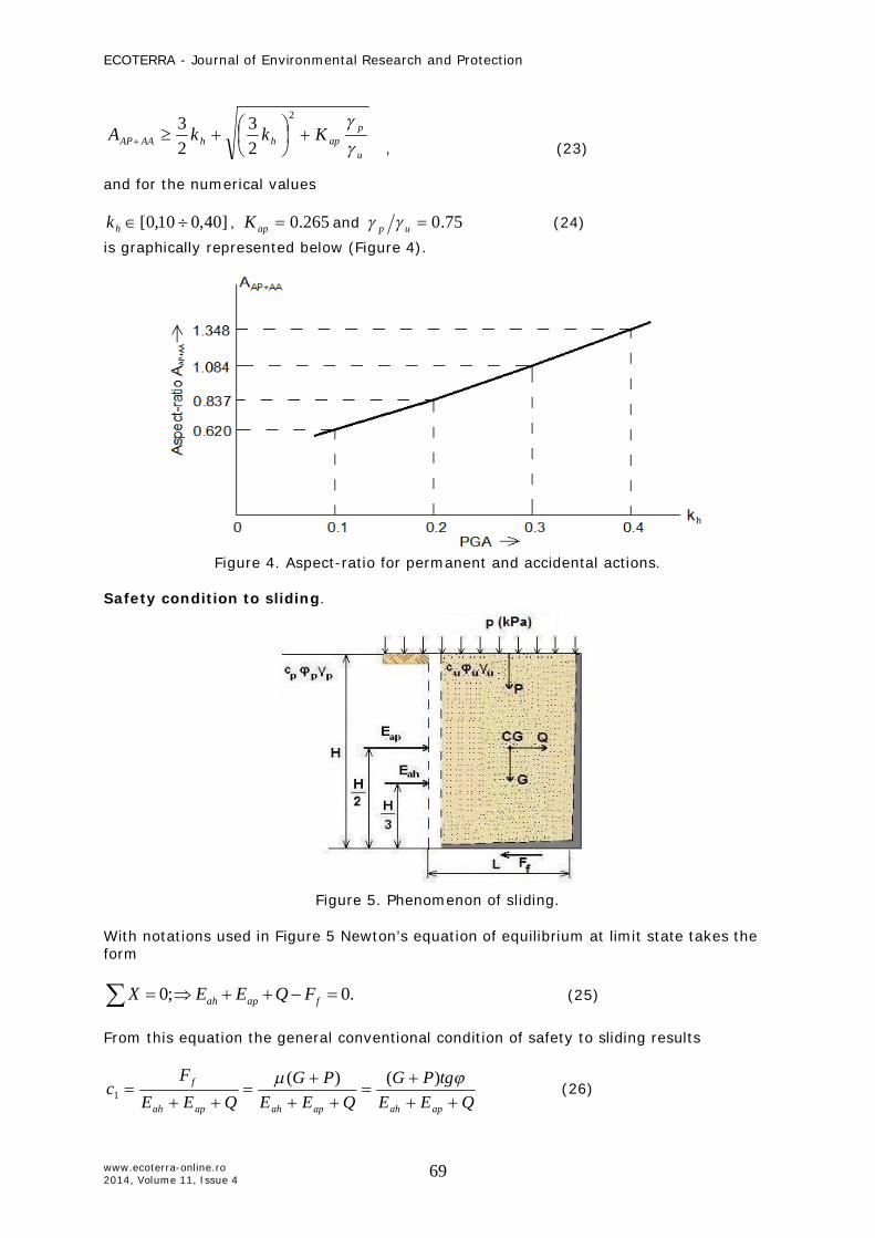
Safety condition to sliding.
Figure 5. Phenomenon of sliding.
With notations used in Figure 5 Newton’s equation of equilibrium at limit state takes the form
.0;0 fapah FQEEX (25)
From this equation the general conventional condition of safety to sliding results
QEEtgPG
QEEPG
QEEF
capahapahapah
f
)()(1 (26)
u
paphhAAAP KkkA
2
23
23

ECOTERRA - Journal of Environmental Research and Protection
www.ecoterra-online.ro 2014, Volume 11, Issue 4
70
Explicitly, in the particular case of permanent actions AP only, the expression of safety factor to sliding becomes proportional with the aspect-ratio, namely
HL
Ktg
EGtgc
ap
u
p
u
ah
u
21 (27)
Therefore, the values of aspect-ratio for permanent actions AP, that satisfy the required safety factor to sliding, are defined by the expression
11 21 c
tgK
Au
ap
u
pAP
(28)
and for the numerical values
,75.0up 265.0apK , 30u and ]0.40.1[1 c (29)
is graphically represented in Figure 6.
Figure 6. Aspect-ratio versus safety factor to sliding for parmanent actions only.
Safety condition to overturning
Figure 7. Phenomenon of overturning.

ECOTERRA - Journal of Environmental Research and Protection
www.ecoterra-online.ro 2014, Volume 11, Issue 4
71
With the notations used in Figure 7 Newton’s equation of equilibrium at limit state takes the form
.02
)(2
)(3
;0)( LPGHQEHEM apahA (30)
From this equation the general conventional condition of safety to overturning results
2)(
3
2)(
2 HQEHE
LPGc
apah
. (31)
Explicitly, in the particular case of permanent actions AP only, the expression of safety factor to overturning becomes proportional with the square of aspect-ratio, namely
2
23
3
2
HL
KHE
LGc
p
u
apah
(32)
Therefore, the values of aspect-ratio for permanent actions AP, that satisfy the required safety factor to overturning, are defined by the expression
22 3c
KA
u
papAP
(33)
and for the numerical values
,5.1;0.1;5.0up 265.0apK , and ]0.120.1[2 c (34)
is graphically represented in Figure 8.
Figure 8. Aspect-ratio versus safety factor to overturning for parmanent actions only.

ECOTERRA - Journal of Environmental Research and Protection
www.ecoterra-online.ro 2014, Volume 11, Issue 4
72
Safety condition to settling
Figure 9. Phenomenon of settling.
With notations used in Figure 9 Newton’s equation of equilibrium at limit state takes the form
0)2(;0 lim eLNY (35)
From this equation the general conventional condition of safety to settling results
NeLc lim
3)2(
(36)
where the third-half requirement is fulfilled, namely.
62
)(3 L
PG
HQEHE
NMe
apah
(37)
Explicitly, in the particular case of permanent actions AP only, the expression of safety factor to settling becomes, after successive processions, an implicit function of aspect-ratio, namely
HLL
KHL
cu
u
pap
lim
2
3
3, (38)
and finally the nonlinear algebraic equation results
033
lim3
23
u
papAP
uAP
KALcA

ECOTERRA - Journal of Environmental Research and Protection
www.ecoterra-online.ro 2014, Volume 11, Issue 4
73
With the notation
lim
Lu , for ]5,01,0[ (39)
the non-dimensional equation for aspect-ratio takes the form
0333
23
u
papAPAP
KAcA
(40)
and its unique solution
23
4)( 233
3u
pap
AP
Kcc
A
(41)
for the numerical values
,75.0up 25.0 , 265.0apK , and ]0.40.1[3 c (42)
is graphically represented in Figure 10.
Figure 10. Aspect-ratio versus safety factor to settling for parmanent actions only.
Case study. A structure with the height of retention mH 00.6 is considered. The geotechnical data are:
21;50;/18
30;0;/243
3
ppp
uuu
kPacmkNcmkN
the surcharge kPap 25 , gPGA 30,0 , and for sake of simplicity, for AP only according
to BS 8006:2010, 0.2321 ccc . An aspect-ratio analysis is required.

ECOTERRA - Journal of Environmental Research and Protection
www.ecoterra-online.ro 2014, Volume 11, Issue 4
74
Preliminary calculations
265,021sin121sin1
sin1sin1
p
papK
; 75.02418
u
p
; 3/17.4625 mkN
Hp
H
23.01817.4
p
H
; 17.02417.4
u
H
; 08.048.0300
00.124300
00.624
lim
xxLu
The combinations of analysis actions:
60.045.075.0265.0 xKAu
papAP
%2020.145.054.0
AP
AVAP
AA
%14040.245.008.1
AP
AAAP
AA
%13131.245.004.1
AP
AAAVAP
AA
It is to be noticed that the inequality
08.104.1 AAAPAAAVAP AA
shows that the combination AP+AA is more dangerous than AP+AV+AA, and in both cases the length of base becomes larger than the height of retention with all consequences implied by this extension in horizontal direction. The differences between the three degrees of freedom, sliding, overturning and settlement, are reflected below in the values assumed by the corresponding aspect-ratios.
60.054.017.01
23.03175.0265.01
31
xxxKAuH
pH
u
papAVAP
60.008.175.0265.030.05.130.05.123
23 2
2
xxxKkkA
u
paphhAAAP
Hu
Hpap
Hu
uh
Hu
uhAAAVAP KkkA
323
23
2
60.004.117.42417.4318265.0
17.4242430.05.1
17.4242430.05.1
2
xxxxxx

ECOTERRA - Journal of Environmental Research and Protection
www.ecoterra-online.ro 2014, Volume 11, Issue 4
75
60.034.00.2577.0265.075.05.0
21
11 xxxctgK
Au
ap
u
pAP
60.036.00.275.03265.0
3 22 xxcK
Au
papAP
60.070.02
75.03265,04)08.00.2(08.00.2
23
4)( 2233
3
xxxx
Kcc
A u
pap
AP
For the same factors of safety the aspect-ratios in sliding and overturning are closed. By far the settlement needs more attention. The last value of aspect-ratio is rather unlikely to occur in practice, but it shows that all investigations are worth to be done. A similar comparative analysis has been carried out for some waste transfer stations located in Vatra Dornei, Câmpulung, Fălticeni and Rădăuti in Suceava County, North of Romania. A prefabricated retaining wall of reinforced concrete designed in Germany was proposed through the European Program for all locations. But the four places have three different PGAs, namely 0.10g, 0.15g and 0.20g, varying therefore from simple to double. By taking into that values and changing the prefabricated solution into a cast in-situ one, three distinct projects were proposed (Sofronie 2014). Beside a better control of safety for the three Stations of waste transfer the average cost was reduced with about 33% comparing with the initial prefabricated solution. Conclusions. Both paper objectives were fulfilled. The first one, referring to shaping the cross-sections of retaining structures, was solved by the third-half condition. The bases of retaining walls remain fully compressed and Meyerhof hypothesis for distribution of soil pressure valid. The second objective, that of stability to sliding, overturning and settling, was coherently solved with the relations between aspect-ratios and safety factors. This geometric parameter is mirroring all structural reactions caused by actions and therefore it is worth to be used in design applications. Numerical results, further presented in a study case, prove the usefulness of this original method. Acknowledgements. The opportunity offered by Faculty of Environmental Science and Engineering, particularly by its dean, prof. Alexandru Ozunu, for presenting this paper to the 10th edition of the ELSEDIMA International Conference is gratefully acknowledged by both authors. References Feodorov C., 2012 Optimization of retaining structures made of reinforced soil.
Proceedings of the Twelve National Conference of Geotechnical and Foundations – Iasi, pp.1023-1032.
Feodorov C., Sofronie R., 2013 Safety levels reached by reinforced soil structures. Environmental Engineering and Management Journal 12(2):1535-1545.
Mocanu D. A., 2011 Reduction and prevention the seismic risc of slopes. PhD thesis prepared under the supervision of prof. Ramiro Sofronie and submitted to Technical University of Civil Engineering, Bucharest.
Sofronie R., 2014 Reinforced concrete retaining wall cast in-situ. Stations of waste-transfer located in Vatra Dornei, Câmpulung, Fălticeni and Rădăuti, Suceava County. Expert Report No. 264/2014.

ECOTERRA - Journal of Environmental Research and Protection
www.ecoterra-online.ro 2014, Volume 11, Issue 4
76
Received: 08 October 2014. Accepted: 04 November 2014. Published online: 30 December 2014. Author: Cristina Feodorov, Technical University of Civil Engineering Bucharest, Bd. Lacul Tei 122-124, 020396 Bucharest, Romania, e-mail: [email protected] Ramiro Sofronie, UNESCO Chair, Faculty of Civil and Environmental Engineering, Bucharest, Bd. Marasti 59, 011464 Bucharest, Romania, e-mail: [email protected] This is an open-access article distributed under the terms of the Creative Commons Attribution License, which permits unrestricted use, distribution and reproduction in any medium, provided the original author and source are credited. How to cite this article: Feodorov C., Sofronie R., 2014 Innovative design of retaining structures. Ecoterra 11(4):64-76.