Innovative conductive polymer composite coating for ...
13
HAL Id: hal-02364732 https://hal.archives-ouvertes.fr/hal-02364732 Submitted on 15 Nov 2019 HAL is a multi-disciplinary open access archive for the deposit and dissemination of sci- entific research documents, whether they are pub- lished or not. The documents may come from teaching and research institutions in France or abroad, or from public or private research centers. L’archive ouverte pluridisciplinaire HAL, est destinée au dépôt et à la diffusion de documents scientifiques de niveau recherche, publiés ou non, émanant des établissements d’enseignement et de recherche français ou étrangers, des laboratoires publics ou privés. Innovative conductive polymer composite coating for aircrafts lightning strike protection Vincent Bedel, Antoine Lonjon, Eric Dantras, Michel Bouquet To cite this version: Vincent Bedel, Antoine Lonjon, Eric Dantras, Michel Bouquet. Innovative conductive polymer com- posite coating for aircrafts lightning strike protection. Journal of Applied Polymer Science, Wiley, 2019, 137, pp.1-11. 10.1002/app.48700. hal-02364732
Transcript of Innovative conductive polymer composite coating for ...

HAL Id: hal-02364732https://hal.archives-ouvertes.fr/hal-02364732
Submitted on 15 Nov 2019
HAL is a multi-disciplinary open accessarchive for the deposit and dissemination of sci-entific research documents, whether they are pub-lished or not. The documents may come fromteaching and research institutions in France orabroad, or from public or private research centers.
L’archive ouverte pluridisciplinaire HAL, estdestinée au dépôt et à la diffusion de documentsscientifiques de niveau recherche, publiés ou non,émanant des établissements d’enseignement et derecherche français ou étrangers, des laboratoirespublics ou privés.
Innovative conductive polymer composite coating foraircrafts lightning strike protection
Vincent Bedel, Antoine Lonjon, Eric Dantras, Michel Bouquet
To cite this version:Vincent Bedel, Antoine Lonjon, Eric Dantras, Michel Bouquet. Innovative conductive polymer com-posite coating for aircrafts lightning strike protection. Journal of Applied Polymer Science, Wiley,2019, 137, pp.1-11. �10.1002/app.48700�. �hal-02364732�

OATAO is an open access repository that collects the work of Toulouse researchers and makes it freely available over the web where possible
Any correspondence concerning this service should be sent
to the repository administrator: [email protected]
This is an author’s version published in: http://oatao.univ-toulouse.fr/25087
To cite this version:
Bedel, Vincent and Lonjon, Antoine and Dantras, Eric and
Bouquet, Michel Innovative conductive polymer composite coating for
aircrafts lightning strike protection. (2019) Journal of Applied Polymer
Science, 137. 1-11. ISSN 0021-8995
Official URL: https://doi.org/10.1002/app.48700

Innovative conductive polymer composite coating for aircraftslightning strike protection
Vincent Bedel,1,2 Antoine Lonjon ,1 Éric Dantras,1 Michel Bouquet21CIRIMAT, Université de Toulouse, CNRS, Physique des Polymères, 118 route de Narbonne 31062, Toulouse cedex 09, France2Institut de Recherche Technologique (IRT) Saint Exupéry, 3 rue Tarfaya, CS 34436 31405 Toulouse cedex 4, FranceCorrespondence to: A. Lonjon (E-mail: [email protected])
ABSTRACT: A new kind of high electrical conductive epoxy coating with low filler rate was investigated for lightning strike protection(LSP) of carbon fiber reinforced polymer (CFRP). The coating without CFRP substrate was firstly studied. The influence of silver sub-micronic wires (AgSWs) with a high aspect ratio on the electrical behavior is observed; that is, the electrical resistivity evolution, the cur-rent density value, and the electrical conduction mechanisms as function of temperature. The preponderant electrical conductionmechanism is an Ohmic behavior. The higher level of conductivity obtained is 5.5 × 10⁵ S m−1 for 9% vol of AgSWs. Lightning striketests were carried out on an epoxy/AgSWs coating filled with 8% in volume (74 gsm) and deposited on a CFRP. The ultrasonic testingafter lightning strike on coated CFRP shows no structural delamination and demonstrates the interest of this new route for anefficient LSP. © 2019 Wiley Periodicals, Inc. J. Appl. Polym. Sci. 2019, 137, 48700.
drawbacks, the first work described the introduction of carbonfillers. The literature is meanly focused on carbon fillers dispersionsuch as carbon black,11,12 carbon nanotubes,13–15 carbonnanofibers,16 or graphene.17,18 The conductive behavior is obtainedabove the percolation threshold which depends on the particlesaspect ratio. This phenomenon was described by Balberg et al.19
and Kirkpatrick.20 The lowest values of filler content were obtainedwith CNTs close to 0.05%vol.21 However, the conductivity levelabove the percolation threshold capped at 10−1 S m−1. Better valuesof electrical conductivity are reported with metallic fillers22–29 near103 S m−1 but for a filler content upper than 20%vol. This ratiodecreases drastically the mechanical properties and overweights thecomposite. An increase of the metallic fillers aspect ratio allows usto decrease the filler content.30 In this case, the percolation thresh-old is reached for a volume fraction lower than 1%vol24,31 keepingthe mechanical properties32,33 and the lightweight of the polymercomposites. Best results in epoxy matrix were obtained with silvernanowires31 which exhibit an electrical conductivity around102 S m−1 for particles content lower than 5%vol.
This work examines the electrical behavior of a conductive com-posite coating epoxy/silver submicronic wires (AgSWs) for LSP.The current density as a function of the electric field characteris-tics was studied for different AgSWs volume fraction. The aimwas to develop an epoxy coating with the highest electrical
KEYWORDS: Applications; coatings; thermosets
DOI: 10.1002/app.48700
INTRODUCTION
Thermoset matrices reinforced by carbon fibers (CFRP) are used in aeronautic structural parts since the last decades, mainly for their lightweight. However, CFRP materials are complex and are charac-terized by an intrinsic structural anisotropy. This heterogeneous structure implies various types of electrical conductivity levels with the worst value along the transversal ax.1,2 The electrical conductiv-ity improvement of CFRP remains a challenging task. The high current density observed during lightning strike implies various types of damages,3–5 for example, critical degradations of the mechanical properties by delamination (labeled direct effect3,6). The aeronautical industry has explored different kinds of solutions to preserve the integrity of the composite structure7,8 from lightning current. Currently, the lightning strike protection (LSP) is based on surface metallic inserts to reduce the damages.7,9 These protections could be metallic foil, perforated metallic foil, metallic mesh, or expanded metal foil bonded on the composite structure surface. The design and the morphology of the LSP depend on the protec-ted area. However, this kind of LSP induces a significant overweight associated with an increase of the complexity in composite pro-cess.8,10 The weak value of CFRP electrical conductivity is due to the dielectric behavior of the polymer matrix. An increase of this electrical conductivity could be an alternative strategy to reduce the damage induced by lightning current. To overcome these

conductivity for a filler content lower than 10%vol. The current–voltage curves were studied as a function of temperatures. Thelimit current density was carried out for various filler contents.Finally, a normalized lightning strike test on CFRP was per-formed for the best conductive coating. A comparison with theclassical ECF protection was performed.
MATERIALS AND METHODS
Epoxy Matrix CoatingThe epoxy matrix used in this study is a mixture of MBDA [4,40-methylenebis(N,N-diglycidylaniline)], DGEBA (bisphenol A diglycidylether), and DGEBF (bisphenol-F diglycidyl ether). The amine hard-ener is composed by a DETDA (diethyltoluenediamine) and a DACH(1,2 diaminocyclohexane) supplied by Sicomin for RTM structuralapplications.
Silver Submicronic WiresAgSWs are elaborated with a modified polyol process34 inspiredby Sun and Wiley works.35–37 It consists in the reduction ofAgNO3 with ethylene glycol solution. A unidirectional controlledsilver crystal growth is promoted. The crystal growth is assistedby polyvinylpyrrolidone which is preferentially adsorbed on {100}crystal faces. AgSWs are washed and stored in ethanol. The meandiameter is around 200 nm and 40 μm for the mean length; thatis, an aspect ratio close to 220.34 This polyol process allows toproduce up to 100 g of AgSWs.
Coating ProcessingComposite coatings were elaborated by mixing an ethanol sus-pension of AgSWs in the epoxy part. Then, hardener was poured(stoichiometric ratio 75/25 in mass). The final suspension withepoxy resin and AgSWs was obtained by mechanical and ultra-sonic stirring. The coating was deposited through a paint spraygun at room temperature after the ultrasonic treatment. A glasssheet of 20 × 18 × 1.1 mm was used as substrate for the current–voltage experiment. A dumbbell shape sample was used(Figure 1) to drive the electron flow through a known dimensionsection. Samples have approximately the same channel dimen-sions; the current value was normalized to the section. A specific
attention was paid to decrease the contact resistances between thesample and the wires of the experimental measurement setupwith a colloidal silver liquid.
For the lightning strike tests, the substrate was replaced by CFRPwith a lay-up representative of a structural composite: that is,[(0/45/90/−45)s]s and 500 × 500 × 3 mm. After spraying, all thecoating samples were cured with different steps from 40 to200 �C. The coating thickness was between 40 and 100 μm.AgSWs content was checked by thermogravimetric analysis fromroom temperature to 1000 �C at a heating rate of 20 �C min−1
under synthetic air atmosphere.
Expanded Copper Foil Lightning Strike ProtectionThe LSP coating elaborated in this work is compared to theExpanded Copper Foil73 (ECF73)7 used for aircraft. The ECF73 iscomposed of a prepreg epoxy adhesive with a chopped strand matof glass fiber and an ECF giving a surface density about 73 gsm(grams by square meter). The global surface density of this LSP isaround 170 gsm and is applied on the top of the CFRP with usualvacuum bag processing assisted by temperature ramp up to 180 �C.
Scanning Electron MicroscopyThe dispersion of the AgSWs in the coating was observed byelectronic microscopy with a JEOL JSM 6700F instrument (scan-ning electron microscope, SEM) under a voltage between 10 and19 keV. Backscattered electron and secondary electron detectionmodes were used to increase the contrast between AgSWs andepoxy matrix and to observe the morphology and the repartitionof the fillers into the matrix respectively. The coating edge cutwas obtained at room temperature.
Current–Voltage Measurement and MechanismsCurrent–voltage characteristics of conductive coatings wereobtained with a Keithley SourceMeter 2420 plugged to the samplein four wires mode controlled by a LabVIEW program. The sam-ple was held by two crocodile clips inside a cryostat under heliumatmosphere. An Eurotherm 2408 allowed us to set the tempera-ture. The measurement parameters like the minimum and maxi-mum values of current or tension, the sampling rate (around
Figure 1. The dumbbell shape sample. [Color figure can be viewed at wileyonlinelibrary.com]

25 points per 100 mV), the duration of the electric charge appli-cation (2 s for each point), sample dimensions, and temperatureare implemented in the LabVIEW program. This system allowsus to plot the I–V curves to determine the dynamic resistivityand the dynamic current density, J(A m−2). I–V curves of poly-mer composites filled with carbon38,39 were used to describe theconduction mechanisms. The charge carrier’s mobility andthe conductivity exhibit different behaviors corresponding to thechemical nature of the studied materials. In the case of heteroge-neous materials like polymers and polymer composites, thechemical structure implies localized states inducing a “pseudo-continuum” in the band gap. The conductivity of these heteroge-neous materials was governed by carriers mobility and wasdescribed by two mainly models. The band gap has a decreasingconcentration of localized states between the valence band andthe Fermi level, it is renamed “mobility gap.”40 The borderbetween delocalized states and localized one is named mobilityedge. Mott41 or Efros42 and Shklovskii describe the charge car-riers mobility through the variable range hopping (VRH)model.41 This behavior can be also explained by another mecha-nism: the multiple trapping and release (MTR)43,44 model. Bothare driven by the temperature. For the VHR, the electronic acti-vation between localized states come from two mechanisms,45
tunneling effect and hopping thermally assisted. The second ispredominant at high temperatures. A study46 mentioned thatVHR and MTR models are present in heterogeneous materials;but their prevalence is driven by the temperature. To sum up, atlowest temperature, the VHR model drives the conductivity bytunneling effect. For the intermediate temperatures, hopping isdominant. As the temperature increases, the conductivity mecha-nism switches to MTR. The I–V characteristics of such systems,conductor, semiconductor, or conductive composite have twomeanly behaviour47:
• a linear behavior, which traduces an Ohmic conductivity.• a nonlinear behavior.• I = V
x (with x > 1) which is the characteristic of a tungsten fila-ment for example.
• I = Vx (with x > 1) which is the characteristic of space chargesphenomenon.48,49
The slope of the curve ln(J) = ln(E) allows us to determine theconduction mechanism: that is, slope is equal to 1 for an Ohmicmechanism, and greater than 2 if charge carriers are injected inthe sample.50
Lightning Strike TestThe aim is to observe the effect of the lightning strike current onthe sample morphology and to evaluate the efficiency of the LSP
by ultrasonic characterization. The test conditions were definedby the requirements of the standard ARP5412: Aircraft LightningEnvironment and Related Test Waveforms. The conductiveepoxy coating was compared to the ECF73 7 and we have focusedour interest on area with a moderate risk of lightning impact(a specific zone labeled 2A).
The waveform of the lightning strike is defined for a zone (aero-nautical structures are identified in different areas by a mappingas a function of the probability and the power of the lightningstrike) and could be described by eq. (1) and Table I.
i tð Þ= I0 e−αt −e−βt� � ð1Þ
where I0 is the highest value of the current (A), α is the inverseof the impulsion time in s−1, and β is the inverse of the ascenttime in s−1.
The amount of energy dissipated during the test was described bythe square integration of eq. (1). This value permits to quantifythe damages on the impacted zone. This specific energy(or action integral) is the square of the intensity multiplied bythe impact duration.
The lightning strike tests were carried out at GERAC Electromag-netism Company. The CFRP sample was screwed between an alu-minum frame and the support frame linked to the ground. Thelightning current was applied with a jet diverter placed at 5 cmfrom the sample surface. The measurements were realized with atemperature between 15 and 35 �C, relative humidity lower than85%, and an atmospheric pressure ranging from 84 to 107 kPa.
Ultrasonic TestingAfter the lightning strike test, the sample was inspected by C-scanmode ultrasonic testing. Only longitudinal waves were used to detectdamages inside the volume. The transductor is installed on a motor-ized arm to scan the surface sample (x, y coordinates). It allows usto obtain the defaults distribution and their depth. The ultrasonicwave frequency was 5 Mhz, they were generated by 32 transductors.This frequency allows us to detect size default up to 500 μm.
RESULTS AND DISCUSSION
Submicronic Wires Dispersion in the MatrixThe AgSWs dispersion in the epoxy coating was observed bySEM. The coating surface [Figure 2(a)] and the edge [Figure 2(b)] observations show a homogenous dispersion without largebundles. A slight orientation of the wires due to the elaborationprocess was observed. The AgSWs aspect ratio was preservedafter the spraying process. The nanocomposite coating thicknesswas measured close to 50 μm.
Table I. Waveforms parameters
Waveform I0 (A) α (s−1) β (s−1) Action integral (A2 s) Duration (ms)
A 218 810 11 354 647 265 2.0 × 10⁶ ≤ 0.5
B 11 300 700 2000 2.9 × 10⁴ 5
C 400 N/A N/A N/A 250 ≤ t ≤ 1000
D 109 405 22 708 1 294 530 2.5 × 10⁵ ≤ 0.5

Electrical BehaviorInfluence of AgSWs Content. Figure 3 shows the evolution of thecurrent density as a function of the electric field for several filler con-tents above the percolation threshold. These measurements were
carried out for low levels of electric field. A linear behavior is pointedout. The resistivity decreases with the filler content due to theincrease of the conductive paths. The linear regression ln(J) = ln(E)allows us to obtain a slope value close to 1, corresponding to an
Figure 2. Poly(epoxy)/Ag 2%vol AgSWs SEM images: (a) surface and (b) edge cut.
Figure 3. Current density as a function of electrical field for various AgSWs ratio in epoxy coating.

Ohmic conductivity. The evolution of the average value of the resis-tance is not linear with silver wires content. For example, the currentdensity of the 9%vol sample is not nine time higher than the 1%volsample. The resistance of the 1%vol is 60 times more important.
Test Reversibility. Successive increase and decrease electrical fieldscans were performed. Figure 4 reports results for three filler con-tents. For purpose of clarity, only three filler ratios were presentedbut a similar behavior was observed for all AgSWs content. Forthis electrical field range, the ascent and descent behavior are simi-lar. The current injections through the sample for moderate cur-rent values have not modified the physical or chemical structure ofthe samples. The conductive mechanism looks to be the same.
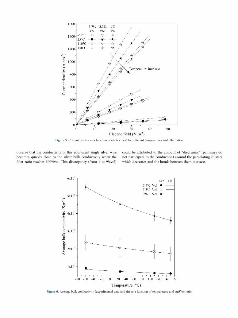
Conductivity Behavior as a Function of Temperature. Figure 5reports the influence of temperature on conductivity for the follow-ing isotherms: −60, 25, 110, and 150 �C. For purpose of clarity, onlythree filler ratios were presented; a similar behavior was observed forall AgSWs content. A linear behavior was pointed out for the variousisotherms. The conductivity associated with the slope was influencedby the temperature increase. Its evolution with the temperature iscomparable to an Ohmic mechanism in metallic materials. This lastmechanism seems to be preponderant, contrary to hopping one clas-sically observed for conductive composites-based polymer.27,51,52
Conductivity evolution as function of temperature is described by thefollowing phenomenological law deduced from the Ohm’s law53–55:
σ Tð Þ= 1ρ0 1 + α T −T0ð Þ½ � ð2Þ
with σ(T) is the electrical conductivity in S m−1, ρ0 is the electri-cal resistivity at the temperature T0 in Ω m, and α is the thermalcoefficient in K−1.
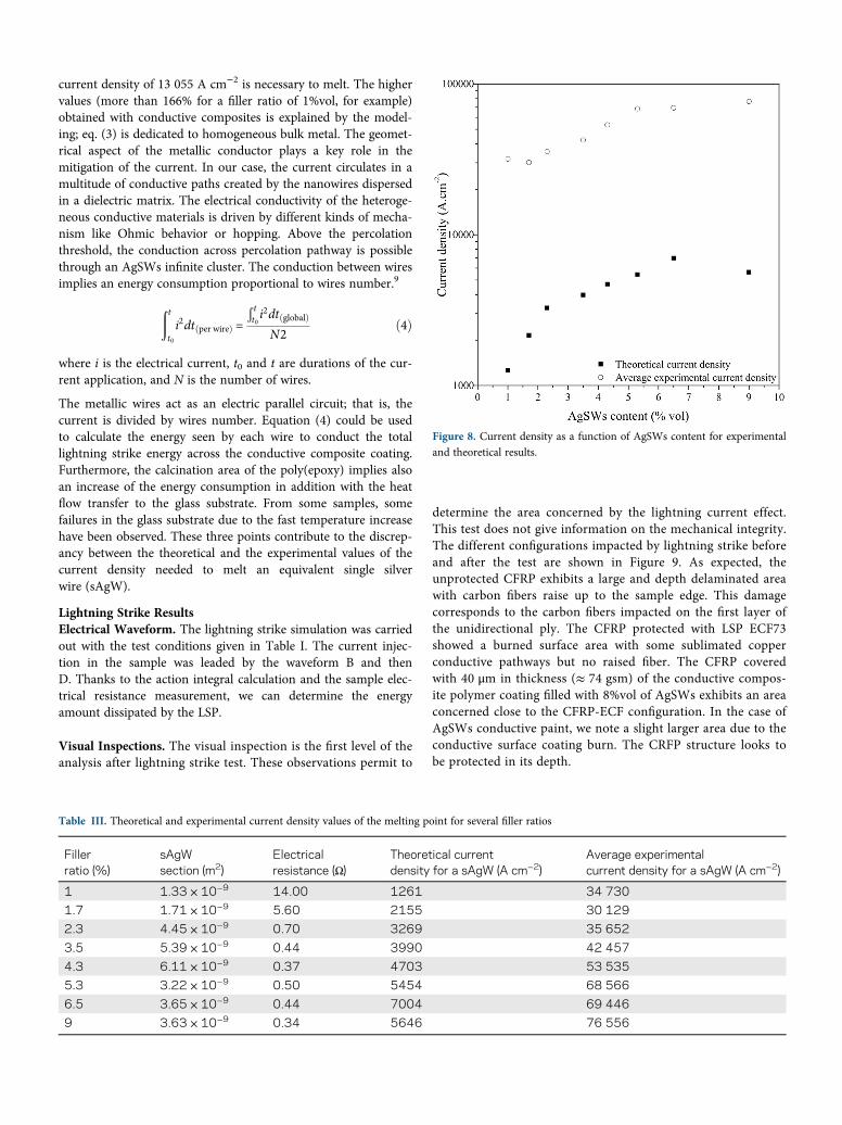
Data extracted from Figure 5 are used to determine the evolutionof the conductivity as function of temperature. J(E) slope isreported in Figure 6 and fitted with eq. (2). The experimentalvalues are well fitted by the model for all filler ratios. Thermalcoefficient values deduced are reported in Table II and are inde-pendent from the filler content. α values for composites are closeto the silver value; the discrepancy with the metal value is proba-bly due to the contact resistances between each AgSWs in theconductive composite coating. This point confirms the similarcomposites behavior regarded to the metallic one.
For 9%vol of AgSWs, Figure 7 reports a conductivity value of5.5 × 105 S m−1. As far as we know, it is the highest conductivityvalue reported in the literature for a composite polymer coatingwith low filler content. The well-known channel section and thevolume filler ratio allow us to calculate the apparent diameter ofan equivalent single wire (sAgW). The evolution does not followa mixing law. The values calculated below are obtained at 25 �C:
9 × 10⁵ � 3 × 10⁵ S m−1 1%vol of Ag SWs.
2 × 10⁶ � 0.8 × 10⁵ S m−1 for the sampled filled by 4.3%vol ofAg SWs.
7 × 10⁶ � 1 × 10⁶ S m−1 for the sampled filled by 9%vol ofAg SWs.
To compare, the silver bulk conductivity was 6.2 × 10⁷ S m−1 at25 �C in the same range of electric field. It is interesting to
Figure 4. Current density as a function of electric field for successive increase and decrease electric field values at 25 �C.
observe that the conductivity of this equivalent single silver wirebecomes quickly close to the silver bulk conductivity when thefiller ratio reaches 100%vol. This discrepancy (from 1 to 9%vol)
could be attributed to the amount of “died arms” (pathways donot participate to the conduction) around the percolating clusterswhich decreases and the bonds between them increase.
Figure 5. Current density as a function of electric field for different temperatures and filler ratios.
Figure 6. Average bulk conductivity (experimental data and fit) as a function of temperature and AgSWs ratio.

Limit Electric Field. The conductive composite coatings wereevaluated by measuring the maximum current density load foreach sample at 25 �C. Figure 7 shows the evolution of the cur-rent density as a function of the electrical field up to thebreakdown.
In the vicinity of the breakdown, the current density valuereaches a maximum (value reported in the inset of Figure 7)described by a plateau. After the breakdown, calcined areas areobserved in the channel. This area is larger when the filler ratiodecreases. The sample was definitively degraded by the suddentemperature increase. This behavior is probably associated withthe melting of AgSWs. In order to confirm this assumption, wecalculate the current value necessary to melt an equivalent bulkmetallic wire,56,57 thanks to the following equation:
Cp:ρv:l:S:ΔT = I2:ρ0 1 + α T−T0ð Þ½ � lSΔt
I =
ffiffiffiffiffiffiffiffiffiffiffiffiffiffiffiffiffiffiffiffiffiffiffiffiffiffiffiffiffiffiffiffiffiffiffiffiffiCp:ρv:S
2:ΔTρ0 1 + α T −T0ð Þ½ �Δt
s=
ffiffiffiffiffiffiffiffiffiffiffiffiffiffiffiffiffiffiffiffiffiffiffiffiCp:ρv:S
2:ΔTρ Tð ÞΔt
sð3Þ
where I is the current in A, Cp is the specific heat capacity in JK−1 kg−1, ρv is the sample density in kg m−3, ΔT is the tempera-ture variation between the ambient temperature and the meltingpoint of the sample, l is the wire length in m, S is the wiresection in m2, ρ0 is the electrical resistivity at the temperature T0
in Ω m, α is the thermal coefficient in K−1, and Δt is the currentapplication time.
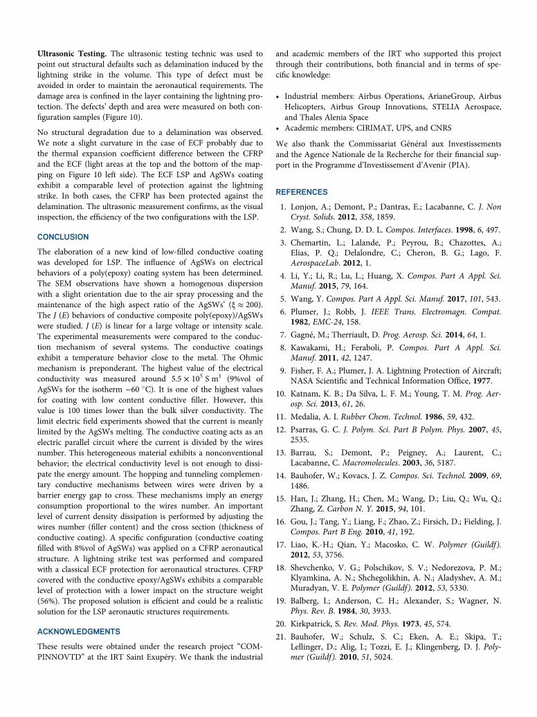
The well-known channel section and the volume filler ratio allowus to calculate the apparent diameter of an equivalent single wire(sAgW). The current value calculated, thanks to eq. (3), and nor-malized by the sAgW section allows us to determine the theoreti-cal current density level at the melting point for each electricalresistivity values (Table III and Figure 8).
We observe a discrepancy between the theoretical and experi-mental values with the increase of AgSWs content. In order tocompare, the same calculation is done for a bulk silver wire; a
Table II. Thermal coefficient values α as a function of filler ratio of AgSWs
Filler ratio (% in volume) α (K−1)
2.3 2.6 × 10⁻³ � 0.1 × 10⁻³
5.3 1.51 × 10⁻³ � 0.05 × 10⁻³
9 2.07 × 10⁻³ � 0.04 × 10⁻³
100 (bulk) 3.42 × 10⁻³ � 1 × 10⁻⁵ K−1
Figure 7. Current density as a function of electric field for several AgSWs ratios at 25 �C. Inset: maximum current density values as a function of the AgSWsvolume content measured at the plateau of J = f(U).
current density of 13 055 A cm−2 is necessary to melt. The highervalues (more than 166% for a filler ratio of 1%vol, for example)obtained with conductive composites is explained by the model-ing; eq. (3) is dedicated to homogeneous bulk metal. The geomet-rical aspect of the metallic conductor plays a key role in themitigation of the current. In our case, the current circulates in amultitude of conductive paths created by the nanowires dispersedin a dielectric matrix. The electrical conductivity of the heteroge-neous conductive materials is driven by different kinds of mecha-nism like Ohmic behavior or hopping. Above the percolationthreshold, the conduction across percolation pathway is possiblethrough an AgSWs infinite cluster. The conduction between wiresimplies an energy consumption proportional to wires number.9
ðtt0
i2dt per wireð Þ =
Ð tt0i2dt globalð ÞN2
ð4Þ
where i is the electrical current, t0 and t are durations of the cur-rent application, and N is the number of wires.
The metallic wires act as an electric parallel circuit; that is, thecurrent is divided by wires number. Equation (4) could be usedto calculate the energy seen by each wire to conduct the totallightning strike energy across the conductive composite coating.Furthermore, the calcination area of the poly(epoxy) implies alsoan increase of the energy consumption in addition with the heatflow transfer to the glass substrate. From some samples, somefailures in the glass substrate due to the fast temperature increasehave been observed. These three points contribute to the discrep-ancy between the theoretical and the experimental values of thecurrent density needed to melt an equivalent single silverwire (sAgW).
Lightning Strike ResultsElectrical Waveform. The lightning strike simulation was carriedout with the test conditions given in Table I. The current injec-tion in the sample was leaded by the waveform B and thenD. Thanks to the action integral calculation and the sample elec-trical resistance measurement, we can determine the energyamount dissipated by the LSP.
Visual Inspections. The visual inspection is the first level of theanalysis after lightning strike test. These observations permit to
determine the area concerned by the lightning current effect.This test does not give information on the mechanical integrity.The different configurations impacted by lightning strike beforeand after the test are shown in Figure 9. As expected, theunprotected CFRP exhibits a large and depth delaminated areawith carbon fibers raise up to the sample edge. This damagecorresponds to the carbon fibers impacted on the first layer ofthe unidirectional ply. The CFRP protected with LSP ECF73showed a burned surface area with some sublimated copperconductive pathways but no raised fiber. The CFRP coveredwith 40 μm in thickness (≈ 74 gsm) of the conductive compos-ite polymer coating filled with 8%vol of AgSWs exhibits an areaconcerned close to the CFRP-ECF configuration. In the case ofAgSWs conductive paint, we note a slight larger area due to theconductive surface coating burn. The CRFP structure looks tobe protected in its depth.
Table III. Theoretical and experimental current density values of the melting point for several filler ratios
Fillerratio (%)
sAgWsection (m2)
Electricalresistance (Ω)
Theoretical currentdensity for a sAgW (A cm−2)
Average experimentalcurrent density for a sAgW (A cm−2)
1 1.33 × 10⁻⁹ 14.00 1261 34 730
1.7 1.71 × 10⁻⁹ 5.60 2155 30 129
2.3 4.45 × 10⁻⁹ 0.70 3269 35 652
3.5 5.39 × 10⁻⁹ 0.44 3990 42 457
4.3 6.11 × 10⁻⁹ 0.37 4703 53 535
5.3 3.22 × 10⁻⁹ 0.50 5454 68 566
6.5 3.65 × 10⁻⁹ 0.44 7004 69 446
9 3.63 × 10⁻⁹ 0.34 5646 76 556
Figure 8. Current density as a function of AgSWs content for experimentaland theoretical results.

Figure 9. Nonimpacted (top) and impacted (bottom) samples without LSP (right), with ECF73 (center) and with AgSWs coating 8% in volume. [Color fig-ure can be viewed at wileyonlinelibrary.com]
Figure 10. On the left, C-scan mapping of a CFRP protected by ECF73 and on the right, AgSWs coating. [Color figure can be viewed atwileyonlinelibrary.com]
Ultrasonic Testing. The ultrasonic testing technic was used topoint out structural defaults such as delamination induced by thelightning strike in the volume. This type of defect must beavoided in order to maintain the aeronautical requirements. Thedamage area is confined in the layer containing the lightning pro-tection. The defects’ depth and area were measured on both con-figuration samples (Figure 10).
No structural degradation due to a delamination was observed.We note a slight curvature in the case of ECF probably due tothe thermal expansion coefficient difference between the CFRPand the ECF (light areas at the top and the bottom of the map-ping on Figure 10 left side). The ECF LSP and AgSWs coatingexhibit a comparable level of protection against the lightningstrike. In both cases, the CFRP has been protected against thedelamination. The ultrasonic measurement confirms, as the visualinspection, the efficiency of the two configurations with the LSP.
CONCLUSION
The elaboration of a new kind of low-filled conductive coatingwas developed for LSP. The influence of AgSWs on electricalbehaviors of a poly(epoxy) coating system has been determined.The SEM observations have shown a homogenous dispersionwith a slight orientation due to the air spray processing and themaintenance of the high aspect ratio of the AgSWs’ (ξ ≈ 200).The J (E) behaviors of conductive composite poly(epoxy)/AgSWswere studied. J (E) is linear for a large voltage or intensity scale.The experimental measurements were compared to the conduc-tion mechanism of several systems. The conductive coatingsexhibit a temperature behavior close to the metal. The Ohmicmechanism is preponderant. The highest value of the electricalconductivity was measured around 5.5 × 10⁵ S m1 (9%vol ofAgSWs for the isotherm −60 �C). It is one of the highest valuesfor coating with low content conductive filler. However, thisvalue is 100 times lower than the bulk silver conductivity. Thelimit electric field experiments showed that the current is meanlylimited by the AgSWs melting. The conductive coating acts as anelectric parallel circuit where the current is divided by the wiresnumber. This heterogeneous material exhibits a nonconventionalbehavior; the electrical conductivity level is not enough to dissi-pate the energy amount. The hopping and tunneling complemen-tary conductive mechanisms between wires were driven by abarrier energy gap to cross. These mechanisms imply an energyconsumption proportional to the wires number. An importantlevel of current density dissipation is performed by adjusting thewires number (filler content) and the cross section (thickness ofconductive coating). A specific configuration (conductive coatingfilled with 8%vol of AgSWs) was applied on a CFRP aeronauticalstructure. A lightning strike test was performed and comparedwith a classical ECF protection for aeronautical structures. CFRPcovered with the conductive epoxy/AgSWs exhibits a comparablelevel of protection with a lower impact on the structure weight(56%). The proposed solution is efficient and could be a realisticsolution for the LSP aeronautic structures requirements.
ACKNOWLEDGMENTS
These results were obtained under the research project “COM-PINNOVTD” at the IRT Saint Exupéry. We thank the industrial
and academic members of the IRT who supported this projectthrough their contributions, both financial and in terms of spe-cific knowledge:
• Industrial members: Airbus Operations, ArianeGroup, AirbusHelicopters, Airbus Group Innovations, STELIA Aerospace,and Thales Alenia Space
• Academic members: CIRIMAT, UPS, and CNRS
We also thank the Commissariat Général aux Investissementsand the Agence Nationale de la Recherche for their financial sup-port in the Programme d’Investissement d’Avenir (PIA).
REFERENCES
1. Lonjon, A.; Demont, P.; Dantras, E.; Lacabanne, C. J. NonCryst. Solids. 2012, 358, 1859.
2. Wang, S.; Chung, D. D. L. Compos. Interfaces. 1998, 6, 497.
3. Chemartin, L.; Lalande, P.; Peyrou, B.; Chazottes, A.;Elias, P. Q.; Delalondre, C.; Cheron, B. G.; Lago, F.AerospaceLab. 2012, 1.
4. Li, Y.; Li, R.; Lu, L.; Huang, X. Compos. Part A Appl. Sci.Manuf. 2015, 79, 164.
5. Wang, Y. Compos. Part A Appl. Sci. Manuf. 2017, 101, 543.
6. Plumer, J.; Robb, J. IEEE Trans. Electromagn. Compat.1982, EMC-24, 158.
7. Gagné, M.; Therriault, D. Prog. Aerosp. Sci. 2014, 64, 1.
8. Kawakami, H.; Feraboli, P. Compos. Part A Appl. Sci.Manuf. 2011, 42, 1247.
9. Fisher, F. A.; Plumer, J. A. Lightning Protection of Aircraft;NASA Scientific and Technical Information Office, 1977.
10. Katnam, K. B.; Da Silva, L. F. M.; Young, T. M. Prog. Aer-osp. Sci. 2013, 61, 26.
11. Medalia, A. I. Rubber Chem. Technol. 1986, 59, 432.
12. Psarras, G. C. J. Polym. Sci. Part B Polym. Phys. 2007, 45,2535.
13. Barrau, S.; Demont, P.; Peigney, A.; Laurent, C.;Lacabanne, C. Macromolecules. 2003, 36, 5187.
14. Bauhofer, W.; Kovacs, J. Z. Compos. Sci. Technol. 2009, 69,1486.
15. Han, J.; Zhang, H.; Chen, M.; Wang, D.; Liu, Q.; Wu, Q.;Zhang, Z. Carbon N. Y. 2015, 94, 101.
16. Gou, J.; Tang, Y.; Liang, F.; Zhao, Z.; Firsich, D.; Fielding, J.Compos. Part B Eng. 2010, 41, 192.
17. Liao, K.-H.; Qian, Y.; Macosko, C. W. Polymer (Guildf).2012, 53, 3756.
18. Shevchenko, V. G.; Polschikov, S. V.; Nedorezova, P. M.;Klyamkina, A. N.; Shchegolikhin, A. N.; Aladyshev, A. M.;Muradyan, V. E. Polymer (Guildf). 2012, 53, 5330.
19. Balberg, I.; Anderson, C. H.; Alexander, S.; Wagner, N.Phys. Rev. B. 1984, 30, 3933.
20. Kirkpatrick, S. Rev. Mod. Phys. 1973, 45, 574.
21. Bauhofer, W.; Schulz, S. C.; Eken, A. E.; Skipa, T.;Lellinger, D.; Alig, I.; Tozzi, E. J.; Klingenberg, D. J. Poly-mer (Guildf). 2010, 51, 5024.

22. Gurland, J. Trans. Metall. Soc. aime. 1966, 236, 642.
23. Untereker, D.; Lyu, S.; Schley, J.; Martinez, G.;Lohstreter, L. ACS Appl. Mater. Interfaces. 2009, 1, 97.
24. Lonjon, A.; Laffont, L.; Demont, P.; Dantras, E.;Lacabanne, C. J. Phys. Chem. C. 2009, 113, 12002.
25. Audoit, J.; Laffont, L.; Lonjon, A.; Dantras, E.;Lacabanne, C. Polymer (Guildf). 2015, 78, 104.
26. Nguyen, T. H. L.; Quiroga Cortes, L.; Lonjon, A.; Dantras, E.;Lacabanne, C. J. Non Cryst. Solids. 2014, 385, 34.
27. Ramachandran, L.; Lonjon, A.; Demont, P.; Dantras, E.;Lacabanne, C. Mater. Res. Express. 2016, 3, 085027.
28. Stejskal, J. Chem. Pap. 2013, 67, 814.
29. Kim, J. M.; Jang, K.; Lee, S. J. J. Appl. Polym. Sci. 2019, 136,47927.
30. Lonjon, A.; Dantas, E.; Demont, P.; Lacabanne, C. Pat.WO/2010/012935 (2010).
31. Bedel, V.; Lonjon, A.; Dantras, É.; Bouquet, M. J. Appl.Polym. Sci. 2018, 135, 46829.
32. Lonjon, A.; Demont, P.; Dantras, E.; Lacabanne, C. J. NonCryst. Solids. 2012, 358, 236.
33. Lonjon, A.; Caffrey, I.; Carponcin, D.; Dantras, E.;Lacabanne, C. J. Non Cryst. Solids. 2013, 376, 199.
34. Cortes, L. Q.; Lonjon, A.; Dantras, E.; Lacabanne, C. J. NonCryst. Solids. 2014, 391, 106.
35. Wiley, B.; Sun, Y.; Xia, Y. Langmuir. 2005, 21, 8077.
36. Sun, Y. Adv. Mater. 2002, 14, 833.
37. Sun, Y.; Yin, Y.; Mayers, B. T.; Herricks, T.; Xia, Y. Chem.Mater. 2002, 14, 4736.
38. Coleman, J.; Curran, S.; Dalton, A.; Davey, A.;McCarthy, B.; Blau, W.; Barklie, R. Phys. Rev. B - Condens.Matter Mater. Phys. 1998, 58, R7492.
39. Narkis, M.; Ram, A.; Flashner, F. Polym. Eng. Sci. 1978,18, 649.
40. Mott, N. F. Adv. Phys. 1967, 16, 49.
41. Mott, N. F.; Davis, E. A. Electronic Processes in Non-Crystalline Materials 2nd ed.; Clarendon Press: Oxford,1979.
42. Efros, A. L.; Phys, J. C Solid State Phys. 1976, 2021, 9.
43. Schwarz, R. J. Non Cryst. Solids. 1998, 148, 227.
44. Teyssedre, G.; Laurent, C. IEEE Trans. Dielectr. Electr.Insul. 2005, 12, 857.
45. Baranovski, S. Charge Transport in Disordered Solids withApplications in Electronics; Philipps University Marburg:Germany, 2006.
46. Blaise, G. J. Electrostat. 2001, 50, 69.
47. Dissado, L. A.; Fothergill, J. C. In Electrical Degradationand Breakdown in Polymers; Stevens, G. C., Ed.,P. Peregrinus Ltd.: United Kingdom, 1992.
48. Child, C. D. Phys. Rev. (Series I). 1911, 32, 492.
49. Stallinga, P. Electrical Characterization of Organic Elec-tronic Materials and Devices; John Wiley & Sons: Chiches-ter, UK, 2009.
50. Ramamurthy, P. C.; Malshe, A. M.; Harrell, W. R.;Grego, R. V.; McGuire, K.; Rao, A. M. International Semi-conductor Device Research Symposium; IEEE:Washington, DC, USA, 2003; p. 208.
51. Sheng, P.; Sichel, E. K.; Gittleman, J. I. Phys. Rev. Lett.1978, 40, 1197.
52. Jovi�c, N.; Dudi�c, D.; Montone, A.; Antisari, M. V.;Mitri�c, M.; Djokovi�c, V. Scr. Mater. 2008, 58, 846.
53. Upadhyay, D. C.; Goyal, E. M.; Goel, J. P. Physics: E-Book.1st ed; SBPD Publications: Meerut, India, 2016.
54. Eccles, W. H. Proc. Phys. Soc. London. 1909, 22, 289.
55. Sondheimer, E. H. Adv. Phys. 1952, 1, 1.
56. Preece, W. H. Proc. R. Soc. London. 1883, 36, 464.
57. Stauffacher, E. R. Gen. Electr. Rev. 1928, 31, 326.