INNOVATIVE APPROACHES TO ELECTROMECHANICAL FLIGHT CONTROL ... · PDF fileRecent Advances in...
7
Recent Advances in Aerospace Actuation Systems and Components, May 5-7 2010, Toulouse, France INNOVATIVE APPROACHES TO ELECTROMECHANICAL FLIGHT CONTROL ACTUATORS AND SYSTEMS Markus Christmann EADS Innovation Works TCC6, Energy and Propulsion 81663 Munich, Germany Phone: +49 (0)89 607-20159 Fax: +49 (0)89 607-21717 Email: [email protected] Sebastian Seemann EADS Innovation Works TCC6, Energy and Propulsion 81663 Munich, Germany Phone: +49 (0)89 607-20874 Fax: +49 (0)89 607-21717 Email: [email protected] Dr. Peter Jänker EADS Innovation Works TCC6, Energy and Propulsion 81663 Munich, Germany Phone: +49 (0)89 607-27825 Fax: +49 (0)89 607-21717 Email: [email protected] ABSTRACT This paper focuses on key challenges of electromechanical actuation systems with multiple degrees of freedom for two specific applications. One is an electromechanical fixed wing trailing edge flap actuation system enabling both differential and asymmetric flap setting for a transport aircraft. The second one is an electromechanical actuation system for the swashplate of a helicopter. To optimize the system weight, initial fit cost and MTBF of the trailing edge flap actuation system different system topologies are investigated. Further innovative approaches are invented for feedback sensors, electric motors, mechanical transmissions and control systems trying to take benefit from the specifics of the electromechanical actuators like their inherent positioning accuracy, high control bandwidth and speed independent torque limiting capability. The swashplate system of a helicopter provides lift, pitch and roll control. The loss of any of these control functions is classified catastrophic mandating a very robust and fault- tolerant design of the 3-degree-of-freedom swash plate actuation system. Different architectures of such actuation system are presented that are fail-operative regarding major mechanical failures and dual-fail-operative for all other failure modes whose probability is not extremely remote. These architectures are evaluated in terms of technological risk, weight, and installation space. KEYWORDS EMA, flight control, swashplate, helicopter, actuator, actuation system, fault-tolerance, trailing edge flap I INTRODUCTION Future flight control system architectures will be based on “More Electric” or even “All Electric” concepts promising benefits mainly in terms of efficiency, weight and maintenance. Even though electric actuation is gaining considerable momentum competing with conventional hydraulic systems the big challenge in designing electromechanical actuation systems is to achieve both quantifyable improvements and compliance with the stringent requirements in terms of environment, operational reliability and safety [1]. 1.1 Trailing edge flap actuation system The high lift system of large transport aircraft comprises leading edge slats and trailing edge flaps and is deployed during take-off and final approach, providing additional lift to get or stay airborne at low speeds. Most current production flap drive systems have a low efficiency, require a high installation effort with shafts and gearboxes distributed across most of the wing trailing edges and offer no functional flexibility like e.g. differential surface deflection. For some modern a/c designs (e.g. 787, A350) additional functions like differential flap setting are implemented by an evolutionary change to established flap drive system concepts [2, 3, 4, 5]. It is proposed and investigated in this paper to develop a distributed electrical flap drive system that is completely integrated with the flap support structures. This new technology is an enabler for new functionalities, which are or have been developed and assessed in related research (e.g. AWIATOR and NACRE [6] projects). It may also provide an increase in the fault tolerance of the high lift system. The presented work was carried out under the NEFS project (New track integrated Electrical Flap drive System) which is funded under the 6th Framework Program (FP6) of the European Commission and Coordinated by EADS Innovation Works [7]. The project team involves 13 partners from industry and academia. The project duration is from March 2007 to June 2011.
Transcript of INNOVATIVE APPROACHES TO ELECTROMECHANICAL FLIGHT CONTROL ... · PDF fileRecent Advances in...

Recent Advances in Aerospace Actuation Systems and Components, May 5-7 2010, Toulouse, France
INNOVATIVE APPROACHES TO ELECTROMECHANICAL FLIGHTCONTROL ACTUATORS AND SYSTEMS
Markus ChristmannEADS Innovation Works
TCC6, Energy and Propulsion81663 Munich, Germany
Phone: +49 (0)89 607-20159Fax: +49 (0)89 607-21717
Email: [email protected]
Sebastian SeemannEADS Innovation Works
TCC6, Energy and Propulsion81663 Munich, Germany
Phone: +49 (0)89 607-20874Fax: +49 (0)89 607-21717
Email: [email protected]
Dr. Peter JänkerEADS Innovation Works
TCC6, Energy and Propulsion81663 Munich, Germany
Phone: +49 (0)89 607-27825Fax: +49 (0)89 607-21717
Email: [email protected]
ABSTRACT
This paper focuses on key challenges of electromechanicalactuation systems with multiple degrees of freedom for twospecific applications. One is an electromechanical fixed wingtrailing edge flap actuation system enabling both differentialand asymmetric flap setting for a transport aircraft. Thesecond one is an electromechanical actuation system for theswashplate of a helicopter.To optimize the system weight, initial fit cost and MTBF ofthe trailing edge flap actuation system different systemtopologies are investigated. Further innovative approachesare invented for feedback sensors, electric motors,mechanical transmissions and control systems trying to takebenefit from the specifics of the electromechanical actuatorslike their inherent positioning accuracy, high controlbandwidth and speed independent torque limiting capability.The swashplate system of a helicopter provides lift, pitch androll control. The loss of any of these control functions isclassified catastrophic mandating a very robust and fault-tolerant design of the 3-degree-of-freedom swash plateactuation system. Different architectures of such actuationsystem are presented that are fail-operative regarding majormechanical failures and dual-fail-operative for all otherfailure modes whose probability is not extremely remote.These architectures are evaluated in terms of technologicalrisk, weight, and installation space.
KEYWORDS
EMA, flight control, swashplate, helicopter, actuator,actuation system, fault-tolerance, trailing edge flap
I INTRODUCTION
Future flight control system architectures will be based on“More Electric” or even “All Electric” concepts promising
benefits mainly in terms of efficiency, weight andmaintenance. Even though electric actuation is gainingconsiderable momentum competing with conventionalhydraulic systems the big challenge in designingelectromechanical actuation systems is to achieve bothquantifyable improvements and compliance with thestringent requirements in terms of environment, operationalreliability and safety [1].
1.1 Trailing edge flap actuation system
The high lift system of large transport aircraft comprisesleading edge slats and trailing edge flaps and is deployedduring take-off and final approach, providing additional liftto get or stay airborne at low speeds.Most current production flap drive systems have a lowefficiency, require a high installation effort with shafts andgearboxes distributed across most of the wing trailing edgesand offer no functional flexibility like e.g. differential surfacedeflection. For some modern a/c designs (e.g. 787, A350)additional functions like differential flap setting areimplemented by an evolutionary change to established flapdrive system concepts [2, 3, 4, 5].It is proposed and investigated in this paper to develop adistributed electrical flap drive system that is completelyintegrated with the flap support structures. This newtechnology is an enabler for new functionalities, which are orhave been developed and assessed in related research (e.g.AWIATOR and NACRE [6] projects). It may also providean increase in the fault tolerance of the high lift system.The presented work was carried out under the NEFS project(New track integrated Electrical Flap drive System) which isfunded under the 6th Framework Program (FP6) of theEuropean Commission and Coordinated by EADSInnovation Works [7]. The project team involves 13 partnersfrom industry and academia. The project duration is fromMarch 2007 to June 2011.

Recent Advances in Aerospace Actuation Systems and Components, May 5-7 2010, Toulouse, France
1.2 Swashplate actuation system
One peculiarity of electromechanical actuators (EMAs)compared to well established and field proven hydraulicactuators is that the mechanical jam of an electromechanicalactuator has to be considered as a credible failure with aprobability of occurrence of larger than 10-8 per flight hour.This is due to the fact that EMA operation relies onmechanical components not being certified as critical parts –and thus not being trusted never to fail – e.g. ball screws orroller screws, respectively. Since in a conventionalswashplate actuation arrangement comprising three actuators,the jamming of any one of those actuators would becatastrophic, the system has to be designed jam-tolerant –either by conceiving an appropriate actuator arrangement orby providing highly available, jam-tolerant actuators.Previous work is reported in [8], [9] and [10].This paper focuses on the introduction of arrangementvariants using customized EMAs based on existenttechnology and satisfying the safety requirements of aprimary flight control system by providing sufficient systemredundancy. A twofold strategy is pursued to identifypromising actuation architecture variants. First, a top-downapproach is made investigating several actuator arrangementsoperating the swashplate. Secondly, the design of possiblesystem architectures is presented in a bottom-up approach.The need for additional safety devices is discussed, namelypower-off brakes and disconnect devices. Availabilityrequirements for these devices are derived from the safetyanalysis data of the respective system architecture. Finally,the results of both a quantitative weight assessment and asemi-quantitative evaluation based on defined target criteriaare presented.
II TRAILING EDGE FLAPACTUATION SYSTEM – NEFSPROJECT
2.1 Objectives and expected benefits
The main objective of NEFS is to develop an alternative to a“traditional” flap drive system comprising a distributedelectrical flap drive system that is completely integrated intothe flap support structure (Figure 1). This includes a redesignof the flap beam providing the opportunity for an innovativecomposite design and enabling an optimized system-structure solution. The focus in this paper will however be onthe project activities regarding system design.The expected benefits of the proposed flap drive system are: new functionalities of the high lift system via differential
flap setting (DFS), like accelerated vortex decay, roll trimand roll control support
reducing operational interruptions caused by high liftsystems
improving the drive system efficiency L/D improvement in cruise weight reduction of the flap track beam due to highly
integrated composite design cost reduction in the manufacturing and assembly of the
flap track beam due to the minimized number of parts improved maintainability
reduced installation effort (for design and manu-facturing).
The joint research effort of the consortium members willenable them to evaluate the benefit of the investigatedapproach and to apply the validated technologies for futureadvanced aircraft and wing configurations.
Aluminum track beam Composite track beamMechanically coupled Electronic synchronizationHydraulic power Electric powerFuselage & wing mounted Track beam integrated
Figure 1 : Main objectives of the NEFS project
2.2 Project Consortium
To achieve the objectives set out in the previous chapter, aconsortium was formed comprising EADS and Airbus as thesystem integrator and producer of the end-product, majorplayers and expert SMEs (Small and Medium sizedEnterprises) of the European aircraft system supplier industry(Diehl, Saab, Goodrich, BAE-Systems, Stridsberg),aerospace structure suppliers (RUAG, ACE) as well asuniversities and research institutions providing front endresearch in the affected fields of technology (DLR,University of Kaiserslautern, Aalto University (Helsinki) andWarsaw University of Technology).An overview on the national composition of the consortiumand the budget breakdown by type of organization is shownin Figure 2.
Figure 2: Budget share by nationality and organization type
2.3 System Architecture
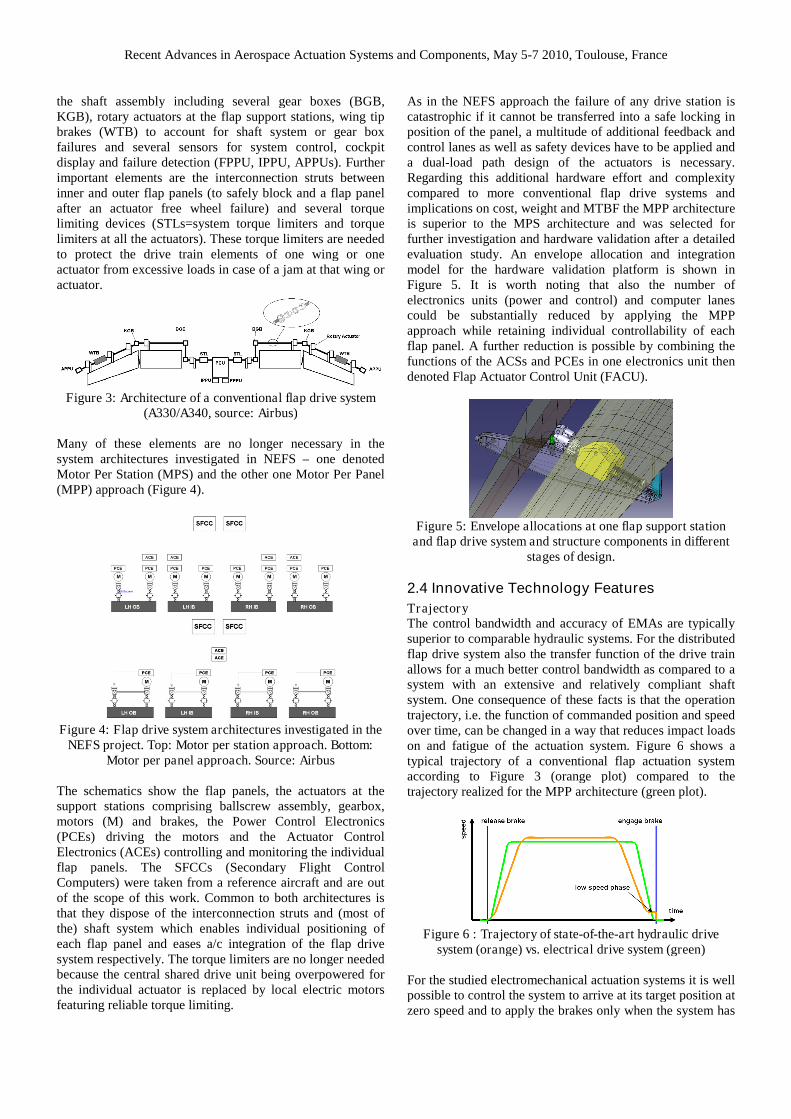
Symmetric flap actuation on both wings is paramount forsafe flight and is traditionally assured by coupling all flapsurface actuators to a torque shaft system, which extendsalong the rear spar of both wings and is driven by acentralized hydraulic, electric or hybrid motor (PCU). Theactuators are located at or near special flap support structureswhich transmit the lift produced by the movable flap surfacesto the wing. The system architecture of a conventional flapdrive system is displayed in Figure 3. The system features
Recent Advances in Aerospace Actuation Systems and Components, May 5-7 2010, Toulouse, France
the shaft assembly including several gear boxes (BGB,KGB), rotary actuators at the flap support stations, wing tipbrakes (WTB) to account for shaft system or gear boxfailures and several sensors for system control, cockpitdisplay and failure detection (FPPU, IPPU, APPUs). Furtherimportant elements are the interconnection struts betweeninner and outer flap panels (to safely block and a flap panelafter an actuator free wheel failure) and several torquelimiting devices (STLs=system torque limiters and torquelimiters at all the actuators). These torque limiters are neededto protect the drive train elements of one wing or oneactuator from excessive loads in case of a jam at that wing oractuator.
Figure 3: Architecture of a conventional flap drive system(A330/A340, source: Airbus)
Many of these elements are no longer necessary in thesystem architectures investigated in NEFS – one denotedMotor Per Station (MPS) and the other one Motor Per Panel(MPP) approach (Figure 4).
Figure 4: Flap drive system architectures investigated in theNEFS project. Top: Motor per station approach. Bottom:
Motor per panel approach. Source: Airbus
The schematics show the flap panels, the actuators at thesupport stations comprising ballscrew assembly, gearbox,motors (M) and brakes, the Power Control Electronics(PCEs) driving the motors and the Actuator ControlElectronics (ACEs) controlling and monitoring the individualflap panels. The SFCCs (Secondary Flight ControlComputers) were taken from a reference aircraft and are outof the scope of this work. Common to both architectures isthat they dispose of the interconnection struts and (most ofthe) shaft system which enables individual positioning ofeach flap panel and eases a/c integration of the flap drivesystem respectively. The torque limiters are no longer neededbecause the central shared drive unit being overpowered forthe individual actuator is replaced by local electric motorsfeaturing reliable torque limiting.
As in the NEFS approach the failure of any drive station iscatastrophic if it cannot be transferred into a safe locking inposition of the panel, a multitude of additional feedback andcontrol lanes as well as safety devices have to be applied anda dual-load path design of the actuators is necessary.Regarding this additional hardware effort and complexitycompared to more conventional flap drive systems andimplications on cost, weight and MTBF the MPP architectureis superior to the MPS architecture and was selected forfurther investigation and hardware validation after a detailedevaluation study. An envelope allocation and integrationmodel for the hardware validation platform is shown inFigure 5. It is worth noting that also the number ofelectronics units (power and control) and computer lanescould be substantially reduced by applying the MPPapproach while retaining individual controllability of eachflap panel. A further reduction is possible by combining thefunctions of the ACSs and PCEs in one electronics unit thendenoted Flap Actuator Control Unit (FACU).
Figure 5: Envelope allocations at one flap support stationand flap drive system and structure components in different
stages of design.
2.4 Innovative Technology Features
TrajectoryThe control bandwidth and accuracy of EMAs are typicallysuperior to comparable hydraulic systems. For the distributedflap drive system also the transfer function of the drive trainallows for a much better control bandwidth as compared to asystem with an extensive and relatively compliant shaftsystem. One consequence of these facts is that the operationtrajectory, i.e. the function of commanded position and speedover time, can be changed in a way that reduces impact loadson and fatigue of the actuation system. Figure 6 shows atypical trajectory of a conventional flap actuation systemaccording to Figure 3 (orange plot) compared to thetrajectory realized for the MPP architecture (green plot).
Figure 6 : Trajectory of state-of-the-art hydraulic drivesystem (orange) vs. electrical drive system (green)
For the studied electromechanical actuation systems it is wellpossible to control the system to arrive at its target position atzero speed and to apply the brakes only when the system has

Recent Advances in Aerospace Actuation Systems and Components, May 5-7 2010, Toulouse, France
come to rest. In the conventional system the central motor isthrottled down to a lower speed when approaching the targetposition. Once the target position threshold is reached thebrakes are applied into the running system causing impactload peaks and possibly fatigue to the brakes.
High performance brakesThe distributed flap actuation system under investigationfeatures a much lower system inertia and higher stiffnessthan architectures with a central drive unit and an extensiveshaft system. While this is beneficial for a good controlperformance it also has drawbacks: In case of free wheelfailures of individual actuators or mechanical failures ofdrive train components the low inertia in combination withhigh aerodynamic loads on the flaps leads to a very rapidacceleration and development of asymmetry between ortwisting/skewing of flap panels. Both are potentialcatastrophic hazards for the aircraft. Thus brakes aredesigned into the actuation system that are capable ofarresting the flap panel through a secondary load path.The requirements for these brakes are quite challenging.Their torque must be high enough to overcome aerodynamicloads and to quickly decelerate the system while at the sametime their reaction must be extremely swift to limitasymmetry/skew/twist built up before the brake torque isbeing applied. Further the maximum torque applied from thebrake may become a limit load for drive train components.Figure 7 displays the maximum allowable time until thebrake starts to exert force after a free wheel failure. This timeincludes the built up of a detectable error signal, propagationdelays and confirmation cycles in the control system and theengagement delay of the brake itself. The k-factor providedin Figure 7 and Figure 8 is defined by the maximum braketorque related to the maximum torque required to react theaerodynamic loads and is thus a measure of brake authority.The higher the brake authority and the higher the massmoment of inertia of the system the longer is the allowabletotal brake engagement delay. A typical value for the systeminvestigated in this paper is 20ms.Making assumptions for the aerodynamic loads, theengagement delay associated with the brake and the“propagation delay” in the control system one can deduce thenecessary monitoring thresholds when using the speed orposition signal to detect the free wheel failure. The results forvalues typical for the investigated system are shown inFigure 8.
Figure 7 : Minimum brake engagement delay as a function ofbrake authority and system inertia
Figure 8 : Monitoring thresholds as a function of brakeauthority and system inertia. Left: position, right: speed
Magnetic gear unitGearboxes are a typical element of EMA systems to adaptthe high speeds and low torques of an electric motor in aweight optimized system solution to the actuation loads andspeeds actually required.In the NEFS project Goodrich Actuation Systems isinvestigating the application of a magnetic gear unit insteadof a mechanical one (Figure 9). Advantages of magnetic gearboxes are the inherent torque limiting feature and the absenceof mechanical contacts and play. The first may lead to lowerdesign loads and reduced weight of system componentswhereas the latter avoids fatigue problems common withmechanical gears.
Figure 9 : Schematic of magnetic gear unit. Source:Goodrich.
Geared GMR duplex position feedbackAnother innovation applied in the NEFS project to a flapactuator developed by Saab Avitronics is a duplex GMR(giant magnetoresistive effect) based geared multi-turnangular position transducer (Figure 10) which is morecompact and lightweight than conventionally used LVDTs orRVDTs. Further it features multiple sensing stages, internalsignal processing and digital communication interfacesproviding for a much better resolution especially at a highrange of revolutions.
Figure 10 : Geared duplex GMR angular position transducer
High p.u. inductance motor designsHigh p.u. inductance motor designs along with some otherspecial motor design features like mechanical, magnetic andthermal segregation of the stator phase windings are commonto applications where for safety and system availabilityreasons several redundant electric motors are used in a torque

Recent Advances in Aerospace Actuation Systems and Components, May 5-7 2010, Toulouse, France
summing arrangement [11]. This is the case for the actuationsystems investigated in this paper.In a torque summing arrangement a failed motor with a shortcircuit fault will still continue to turn driven by the redundantunit. When applying the very weight efficient permanentmagnet synchronous motor (PMSM) technology this resultsin the failed motor, phase winding or winding turn to operatein a generator mode. Standard electric motors feature per unitphase inductances in the order of magnitude of 0.1p.u. whichcorresponds to the lines plotted in blue in Figure 11. One caneasily see that the normalized thermal losses (left) andbraking torque (right) become prohibitive. Suitable per unitinductances are in the range of 0.7 to 1p.u. Higher values –although beneficial for motor thermal losses and brakingtorque – have negative implications on the motor driveelectronics (PCE) as at a given available voltage level thisresults in a higher necessary current rating of the unit.Within the NEFS project Goodrich Actuation Systems andSaab Avitronics in cooperation with Stridsberg AB areresponsible for the development of bespoke electric motors.The designs are already successfully validated by simulation.
Figure 11 : Losses and braking torque of a shorted electricmotor as a function of winding inductance and speed
III SWASHPLATE ACTUATIONSYSTEM
3.1 Actuation Arrangements
EADS IW designed a set of possible actuation arrangementsemerging from the top-down approach. Three concepts areshown in Figure 12 – Serial, Parallel, and Groupedpositioning of the actuators. They all rely on the basic idea toprovide jam tolerance by means of redundant actuators,whereas their operation philosophies differ substantially.
Figure 12: Serial, Parallel, and Grouped concept
The failure management of all three concepts relies on thefact that each actuator is capable of compensating theperformance of a faulted adjacent actuator. As to the Serialand Parallel arrangement, the mechanical jam of a singleactuator can be tolerated. However, a free wheeling actuatorwould result in the free wheel of one of the three legs, being
tantamount to the loss of control of the entire flight controlsystem. As a consequence, an additional power-off brake isrequired as a safety device blocking the screw of the affectedactuator.Since each of the six EMAs of the Grouped concept has itsown attachment point at the swashplate, a free wheel couldbe compensated, whereas a mechanical jam would becatastrophic. Thus each actuator must be equipped with adisconnect device mechanically converting the jam into afree wheel.
3.2 Optimizing Redundancy
The required number of redundant components for thedifferent swashplate actuator arrangements can bedetermined by combining the quantified failure modes ofmechanical and electrical components [12] with simpleMarkov models.As to the electric motors, this analysis indicates the need forat least two motors per actuator, i.e. 12 motors in total forthe actuator arrangements displayed in Figure 12. Each ofthem needs its associated power stage. A straightforwardapproach would require the same amount of Actuator ControlElectronics (ACEs) each providing two lanes (command andmonitor) to facilitate failure detection. This yields 24computer lanes in total, with the corresponding negativeimplications on weight, cost and MTBF (mean time betweenfailures). However, the command functions can be integratedin a reduced number of ACEs while still complying with thesafety requirements. The reduction potential is assessed bymeans of a permutation analysis. Figure 13 shows twoexamples for the Serial and the Parallel concept (identicalcontrol architecture) with the vertical rectangles and theadjacent circles representing actuators (mechanical part) andmotors.
Figure 13: ACE permutation
Using six ACEs, three different degraded modes are possibleafter the failure of two ACEs (which is more severe than thefailure of two electric motors or power stages). Reducing thenumber to a total of only three ACEs and applying the propermapping of ACEs to electric motors, just one scenario has tobe taken into account. Even though component losses are

Recent Advances in Aerospace Actuation Systems and Components, May 5-7 2010, Toulouse, France
more severe than for system architectures comprising a largernumber of ACEs, safety requirements can still be met – andat a better system MTBF due to lower part count.Design load assessments considering the relevant failurecases of all concepts reveal that a reduced number of ACEsresults in significantly increased motor and actuator loads forsome of the variants and permutation mappings, whereas itdoes not have any effect on the design loads for others. Thus,the benefits in terms of mass and cost reduction achieved bythe reduced number of ACEs can be fully exploited for thelatter. For the first group of system architectures thesebenefits have to be traded against the increased design loadsof power electronics, motors and actuators and theirimplications.An exemplary system architecture for the Serial arrangementis shown in Figure 14. It is apparent that the utilization of areduced number of ACEs is reasonable for this designvariant. Relying on the shown permutation, the system iscapable of surviving even two arbitrary component failures(except a jam).
Figure 14: System architecture of Serial concept
3.3 Safety Analysis
In order to quantitatively prove compliance with thecertification specifications, safety analysis in terms of a FaultTree Analysis (FTA) is performed. A combination of FTAand Markov models according to the standard EN 61025 isconducted, allowing to simplify the fault trees significantly[13]. All actuators being identical in terms of componentsand operation, it is sufficient to model a single actuator andto insert a Markov model above acting as a multiplicator.The safety analysis proves the required system availability tobe achieved, and identifies the weak spots within thearchitecture. For each of the investigated concepts, theparticular safety device, i.e. the power-off brake or thedisconnect device, respectively, turns out to be by far themost critical component. Two main requirements emergefrom the analysis.
Figure 15: Markov model for safety device requirements
First, the respective safety device may not fail in case it isneeded. For instance, the power-off brake of one actuator inthe Serial arrangement may not fail to engage if both motorsof this actuator failed. Second, the safety device must notunintentionally be activated. E.g. two unintended brakeengagements at the same leg of the Serial concept would becatastrophic. Figure 15 shows the according Markov modelsfor the described scenarios.
3.4 Evaluation and mass assessment
To perform a down-selection of the devised system conceptsa suitability score for each of the concepts is calculated usinga method for technical evaluation. The global score for eachconcept is determined as a weighted average of a set ofdefined target criteria:
Mass Installation space Technological Risk Complexity
To obtain a representative collection of technical parametersa selection of easily quantifiable technological characteristicsis defined, e.g. number of motors, design power, actuatorstroke etc. These parameters are assigned to a consistentscale by applying an evaluation metrics based on guidelineVDI 2225 [14]. By means of an “Influence matrix” theinfluence of each characteristic on the particular targetcriteria can be modeled. Depending on the number ofcharacteristics impacting a target criterion, an internalweighting factor is calculated. A balanced score cardincluding the presented variants is shown in Figure 16.
Figure 16: Balanced score card (extract)
As to the overall system mass, detailed analysis has beenperformed by means of a mass assessment of some concepts.It is based on the loads derived under consideration of allrelevant failure cases and the corresponding models. Usingthe mass of a corresponding hydraulic system as a 100%

Recent Advances in Aerospace Actuation Systems and Components, May 5-7 2010, Toulouse, France
reference, Figure 17 reveals that some of the conceivedelectromechanical actuation systems are capable to competewith their hydraulic counterpart in terms of system mass.Arrangement 3 refers to the Grouped arrangement introducedearlier in this paper whereas arrangements 1 and 2 are furtherconcepts that were investigated. The fourth bar represents a3-EMA arrangement which is 1 fail-operative with respect toall electrical and some mechanical failures but without anyjam tolerance (similar to present hydraulic swashplateactuation systems). It is obvious that – if applying the sameredundancy level than provided in today’s helicopters – anEMA system could well compete with its hydrauliccounterpart in terms of weight.
Figure 17: System mass comparison
CONCLUSION
“More Electric” and “All Electric” concepts for a/c flightcontrol applications are evolving rapidly and promise higherefficiency while constantly improving system weight,envelope, MTBF and cost. This will eventually – rathersooner than later – result in electromechanical flight controlactuation systems replacing their hydraulically power orhybrid predecessors. Improvements of EMA systems aretaking place both on the architecture and on the componentlevel. Some aspects of this evolution process have beenpresented in this paper.
NOTATIONS
Variables and parameters
λBrake.SP1 Safety device requirement No. 1 (failedto engage) for Serial concept
λBrake.SP2 Safety device requirement No. 2 (un-commanded engagement) for Serialconcept
λFW.SP1 Free wheel rate of an arbitrary actuatorof the Serial concept (both motors freewheeling)
AKNOWLEDGEMENTS
The work presented in this paper was supported under the 6th
and 7th Framework Programs of the European Commission
and was conducted in the framework of the project NEFS(Contract #030789) and the JTI Clean Sky JTI Systems forGreen Operations ITD.
REFERENCES
[1] J.-J. Charrier, A. Kulshreshtha: Electric Actuation ForFlight & Engine Control System: Evolution, Current Trends& Future Challenges, 45th AIAA Aerospace SciencesMeeting and Exhibit, 2007, Reno, Nevada[2] M. Recksiek: Advanced High Lift System Architecturewith Distributed Electrical Flap Actuation, Aviation SystemTechnology Workshop 2009, 2009, Hamburg, Germany[3] C. Giebeler, M. Recksiek: Development of an IntegratedElectromechanical Actuator for Single Flap Drive Concepts,3rd International Conference on Recent Advances inAerospace Actuation Systems and Components, Toulouse,France 13-15 June 2007[4] C. Giebeler, M. Recksiek, M. Christmann, P. Jänker:Development of an Integrated Electromechanical Actuatorfor Single Flap Drive Concepts, Actuator 2006 – 10thInternationel Conference on New Actuators, Bremen,Germany, 2006[5] J.W. Bennett, B.C. Mecrow, A.G. Jack, D.J. Atkinson, C.Sewell, G. Mason, S. Sheldon, B. Cooper: Choice of DriveTopologies for Electrical Actuation of Aircraft Flaps andSlats, 2004, PEMD[6] http://ec.europa.eu/research/research-for-europe/transport-nacre_en.html[7] www.nefs.eu[8] J.E. Gilmour : Requirements Definition and Qualificationfor a HEAT Fly-By-Wire System, 30th European RotorcraftForum, 2004, Marseille, France[9] A. Staple, A. Handcock : The All-Electric Rotorcraft –Challenges and Opportunities, 28th European RotorcraftForum, 2002, Bristol, UK[10] M. Garrison, S. Steffan: Two-Fault Tolerant ElectricActuation Systems for Space Applications, Conference onChanges in Aeronautical and Space Systems – Challengesfor On-Board Energy, 26-28 June 2006[11] J.W. Bennett, A.G. Jack, B.C. Mecrow, D.J. Atkinson,C. Sewell, G.Mason: “Fault Tolerant Control Architecturesfor an Electrical Actuator”, IEEE PESC Conference 2004,Aachen, Germany[12] MIL-HDBK-217F: Reliability Prediction of ElectronicEquipment, US Department of Defense, Washington, 1991[13] EN 61025: Fault Tree Analysis (IEC 61025:2006), 2007[14] VDI guideline 2225: Design engineering methodics -Engineering design at optimum cost - Valuation of costs,1998