INNOVATIONS AND CHALLENGES DURING URBAN … · 2019-12-08 · INNOVATIONS AND CHALLENGES DURING...
12
INNOVATIONS AND CHALLENGES DURING URBAN DEVELOPMENT – SHORING AND FOUNDATIONS OF CANADA’S TALLEST RESIDENTIAL BUILDING Shawna Munn, P.Eng, Isherwood Geostructural Engineers, Mississauga, Ontario, Canada; 905-820-3480; [email protected] Nadir Ansari, P.Eng, D.GE, M.ASCE Isherwood Geostructural Engineers, Mississauga, Ontario, Canada; [email protected]; Toben Jerry, Senior Vice President GFL Infrastructure Group Inc., Vaughan, Ontario, Canada; [email protected]; ABSTRACT With ever increasing demands on space in urban environments and smaller available footprints, buildings are being designed to increasing heights to meet the need. This case study discusses the increasing challenges in developing projects within urban environments with smaller available footprints and increasing building heights. The One, Canada’s tallest residential building under construction will stand at 85 storeys and is located at one of the most prominent and built up intersections in Toronto, Yonge Street and Bloor Street. This led to many challenges in design and construction of the shoring and foundation work, including the required design capacity of the foundations for the supertall building and proximity of the large diameter drilled shafts to the excavation shoring wall. This case history describes the shoring design option evaluation, performance, and lessons learned to date throughout construction of the building foundations within a small congested site. Keywords: large diameter drilled shafts, performance based design, monitoring, design, excavation shoring, support of excavation, SOE, foundations, frost PROJECT OVERVIEW The One, Canada’s tallest residential building under construction by Mizrahi Developments, is a supertall building that will stand at 85 storeys and 306 m (1005 ft). The first 18 floors will be comprised of retail, restaurants, and hotel with luxury residential condominium units in the tower above. The project is located on the Southwest corner of Yonge Street and Bloor Street, one of the most prominent and built up intersections in Toronto. The L-shaped excavation measures 58 m by 47 m (190 ft to 154 ft) and ranges from 22 m to 28 m (72 ft to 92 ft) in depth with one internal corner projecting 11 m (36 ft) into the site. Fig. 1. Site at Yonge and Bloor (L), and Supertall tower in the Toronto skyline looking South (R) 139 © 2019 Deep Foundations Institute
Transcript of INNOVATIONS AND CHALLENGES DURING URBAN … · 2019-12-08 · INNOVATIONS AND CHALLENGES DURING...

INNOVATIONS AND CHALLENGES DURING URBAN DEVELOPMENT – SHORING AND FOUNDATIONS OF CANADA’S TALLEST RESIDENTIAL BUILDING Shawna Munn, P.Eng, Isherwood Geostructural Engineers, Mississauga, Ontario, Canada; 905-820-3480; [email protected] Nadir Ansari, P.Eng, D.GE, M.ASCE Isherwood Geostructural Engineers, Mississauga, Ontario, Canada; [email protected]; Toben Jerry, Senior Vice President GFL Infrastructure Group Inc., Vaughan, Ontario, Canada; [email protected]; ABSTRACT
With ever increasing demands on space in urban environments and smaller available footprints, buildings are being designed to increasing heights to meet the need. This case study discusses the increasing challenges in developing projects within urban environments with smaller available footprints and increasing building heights. The One, Canada’s tallest residential building under construction will stand at 85 storeys and is located at one of the most prominent and built up intersections in Toronto, Yonge Street and Bloor Street. This led to many challenges in design and construction of the shoring and foundation work, including the required design capacity of the foundations for the supertall building and proximity of the large diameter drilled shafts to the excavation shoring wall. This case history describes the shoring design option evaluation, performance, and lessons learned to date throughout construction of the building foundations within a small congested site.
Keywords: large diameter drilled shafts, performance based design, monitoring, design, excavation shoring, support of excavation, SOE, foundations, frost
PROJECT OVERVIEW
The One, Canada’s tallest residential building under construction by Mizrahi Developments, is a supertall building that will stand at 85 storeys and 306 m (1005 ft). The first 18 floors will be comprised of retail, restaurants, and hotel with luxury residential condominium units in the tower above. The project is located on the Southwest corner of Yonge Street and Bloor Street, one of the most prominent and built up intersections in Toronto. The L-shaped excavation measures 58 m by 47 m (190 ft to 154 ft) and ranges from 22 m to 28 m (72 ft to 92 ft) in depth with one internal corner projecting 11 m (36 ft) into the site.
Fig. 1. Site at Yonge and Bloor (L), and Supertall tower in the Toronto skyline looking South (R)
139 © 2019 Deep Foundations Institute

EXCAVATION SHORING DESIGN OPTIONS AND CONSTRAINTS
The SOE design was driven by a design build tendering process allowing for innovation and design alternatives. This required evaluation of several design options that had to consider the following constraints:
• No encroachment underneath neighbouring buildings to the South and West • Existing deep basements limiting space for tieback anchorage on the East, and Southwest • Existing utilities underneath Bloor Street and Yonge Street on the North and East • Limited access around and under existing heritage building section to be retained in place • Limited space for the shoring footprint on the South and Northwest due to proposed building
footprint proximity to existing buildings, and on the East due to heritage building proximity to existing hydro duct
• Maximizing access for installation of structural caissons from subgrade elevation • Refer to Figure 2 for layout of building foundations and constraints
Fig. 2. One Bloor Street West Foundation Plan and Design Constraints GEOLOGY
The site is generally underlain by shallow earth fill followed by glacial deposits down to the Georgian Bay shale at a depth of approximately 38 m (125 ft). From grade, the glacial deposits consist of stiff to hard varved silt and clay extending up to 15 m (50 ft) below grade (Queen’s Park Clay), very dense to hard sand with some silt from 15 m to 38 m (Queen’s Park Stratum), and hard layered clayey silt glacial till with gravel, cobbles, and boulders from 36 to 38 m (York Till) (Terraprobe 2016). The water table
140

was measured to be approximately 20 m below grade within the cohesionless sands and silts and mandated the use dewatering or impermeable shoring below the water table. OPTION ANALYSIS
Temporary Cutoff Wall
The geotechnical conditions and spatial constraints limited effective dewatering and mandated installation of an interlocking secant pile wall sealed in rock all around the project site. Pile drill depths ranged from 40 m – 43 m below grade and were installed with three rotary drill rigs using segmental liners – two Bauer BG40’s and one Bauer BG55.
Fig. 3. Typical Secant Pile Wall Layout
Where space was limited between the proposed building and existing buildings on the West and South walls, the secant pile wall depth was limited to 580 mm (23”) to allow for desired installation clearance to the adjacent building.
Fig. 4. Secant Pile Wall Adjacent to Existing Buildings on South and West Walls Tied-back Shoring
Where geometry and encroachment agreements allowed, the preferred shoring bracing for design, installation, schedule, and performance reasons was tieback anchors. This design module was used adjacent to both Bloor and Yonge Streets. Anchor lengths were limited to maintain a minimum clearance of 1 m to adjacent structures. This option provided the most access within the site for both excavation and drilling of structural caissons at subgrade.
1180 filler
3340 c/c 610 pile 1180Ø Hole
CL Pile and Hole
360
New Wall
345
1180 filler 1180Ø Hole 450
290
340 1060
300 Min Clear
3340 or 1670 c/c
100 Min Clear
W460x128 Pile
50
CL Pile and Hole
50
345
141

Internal Bracing
An internal bracing scheme was required where encroachment onto adjacent properties was not allowed or deep adjacent structures existed. A corner brace and cross site strut option with king piles was evaluated (Figure 5) but ultimately abandoned due to the excavation challenges and site access challenges it would impose for caisson installation at subgrade by effectively cutting the already small site into two smaller excavations.
Fig. 5. Internal Bracing Scheme with Corner Bracing and Cross Site Strut/King Piles
Partial Hybrid Top Down
A hybrid top down approach was also evaluated for the West and South walls using a section of the permanent slabs as a deep beam to brace the shoring walls (Figure 6). Permanent slab width was limited to avoid conflict with larger diameter caisson locations and changes in the permanent structure geometry, for example the ramp location on South wall. This required the design of supplementary steel truss reinforcement to limit deflection and cracking of the permanent slabs in the temporary condition. Due to deflection compatibility, and therefore load sharing compatibility, the steel truss would have to be preloaded against the shoring wall prior to attachment to the concrete slab. The slab/truss would be braced back to the North and South shoring walls to limit deflection and transfer support load. The slabs would also be used as construction staging areas due to limited space around the perimeter and no option of lane closure on either of the adjacent streets for the duration of the project. These slabs would be used for the excavator platform, material handling and loading, truck loading/unloading, concrete delivery, and concrete pump platform. This option was ultimately passed over due to schedule pressure and constraints on excavation and the permanent structure design still being in-process at the time of design.
142

Fig. 6. Hybrid Top Down Scheme with Typical Example Details
The “Supercorner” and “Superpiles”
In order to facilitate an open excavation, removal of the cross site strut, and load transfer from the South slab bracing to the Northwest slab bracing, the concept of a “supercorner” with anchors through the public laneways was introduced. The supercorner has two double W760 (W30) piles in 1300 mm diameter drilled holes with six supplementary 1180 mm filler secants to transfer load from one section of the shoring to the other with limited deflection. Each superpile was designed with 13 anchors splayed from 15 to 45 degrees, each 1550 kN (348 kips) – the practical installation limit for a 12 strand anchor in a 150 mm (6 inch) post-grouted soil anchor and 115 mm (4.5 inch) rock anchor. The total horizontal anchorage force in each super pile is over 16,500 kN (3700 kips). Refer to Figure 7.
Shoring at Façade
A requirement for the development of the project at The One was to retain the building segment of the existing 774-776 Yonge Street building in place without relocation or dismantling and rebuilding. This did not leave sufficient space to the existing utilities, specifically an existing Toronto Hydro duct, along Yonge Street to install a secant pile wall from grade. Other options evaluated included an anchored
143

shotcrete wall, hybrid micropile shoring/anchor shotcrete wall (to achieve enough clearance with the anchors to existing utilities), and micropile shoring wall full depth with dewatering.
Fig. 7. “Supercorner” Layout and “Superpile” Section
Final Scheme
Ultimately encroachment negotiations were successful with the South neighbour allowing for tied-back shoring on the South wall and elimination of 11 anchors on one of the superpiles. On the Northwest side of the site, the super corner facilitated an internal bracing design with walers and corner braces from the West wall to the super corner and North wall. At the Heritage Building segment, anchored micropile-reinforced shotcrete shoring was used to an excavation depth of 20 m (65 ft) where a lower secant pile wall with anchors was installed to cutoff water for pile cap excavation. The final layout bracing layout is shown in Figure 8.
144

For construction staging, a temporary slab was constructed on the South wall to allow for construction access throughout the duration of the project. This temporary slab also provided bracing for the top of the piles on the South wall.
Fig. 8. Final Shoring Bracing Scheme – View looking South
LARGE DIAMETER DRILLED SHAFT FOUNDATIONS
The building foundation design consists of drilled shafts with up to a 6.5 m socket in rock. Due to the depth to rock, the decision was made to install the larger (>3 m/10ft) diameter caissons from a subgrade elevation near the base of final excavation. Overhead obstructions at the temporary slab, internal bracing, and heritage façade required the majority of the smaller diameter (<1.5 m) to be installed from grade using one BG40 (1.3 m dia. only) and one BG55 with segmental liner casing prior to excavation with the exception of the caissons located underneath the heritage building segment. The caissons located in the centre of the site were also installed from grade to advance the installation of the tower crane footing as it was planned to place the large equipment for subgrade caisson installation into the base of excavation. Table 1 provides a summary of the drilled shaft quantities and average drill depths.
145

Table 1 – Structural Foundation Summary Drill Elevation Diameter – mm (ft) Average Drill Depth – m (ft) Quantity
Grade (115 m ±)
1300 (4.25) 42.3 (138) 17 1500 (5) 43.0 (141) 48
Subgrade (95 m ±)
1300 (4.25) 23.0 (82) 4 3058 (10) 25.3 (83) 24 3353 (11) 25.9 (85) 6
The large diameter caissons were installed from subgrade (-20 m/65 ft) using the APE 400 vibratory driver to drive casing to rock before drilling inside with a BG55 rotary drill. Due to low headroom underneath the heritage building and support structure, a modified low headroom BG24 rig was used to install both the lower secant pile wall and structural caissons (Figure 9).
Fig. 9. Low Headroom BG24 under Façade (L); Driving 10’ dia. liner at subgrade APE400 (R) RISKS TO ADJACENT STRUCTURES Using the vibratory driver installation method for the large diameter caissons involved a balance between efficient installation methodology and risks to adjacent structures including the active excavation shoring, heritage façade, and surrounding structures. The structural caissons adjacent to the shoring ranged in distance to the shoring walls from 6 m (20 ft) to 300 mm (1 ft), creating concern that installation could
146

cause disturbance within the sand layer and result in excessive shoring movement. At the heritage structure, structural caissons were located as close as 3 m from the supporting king piles. Of concern was vibration transmission through the king piles into the sensitive structure above. Finally, limiting vibration transmission through the shoring into adjacent structures to below City of Toronto mandated vibration limits (5mm/s) had to be managed.
MONITORING AND THE OBSERVATIONAL METHOD
Based on the known risks, a monitoring plan was developed to take advantage of the observational method to manage and converge on the areas of highest risk. Figure 10 outlines the excavation monitoring plan for the project including:
Inclinometer Monitoring: At 11 locations around the site to cover various design modules, and at locations adjacent to large diameter structural caissons Shape Accel Array (SAA): At super corner location to provide real time inclinometer readings during tieback stressing, corner brace preloading, and excavation on the Northwest wall Pile Survey Monitoring: Located at the top and mid-span of each pile to correlate inclinometer monitoring, and provide performance coverage between inclinometer locations Slab Survey Monitoring: Along the edge of the South temporary slab support beams in lieu of pile targets due to site line challenges with reading pile targets below slab Façade Survey Monitoring: To monitor façade structure movement during excavation Precision Survey Building Monitoring: At adjacent buildings within the influence of excavation at the South and West Real-time Vibration Monitoring (not shown): In adjacent buildings within the vibration influence and the heritage building
Fig.10. Monitoring Plan for One Bloor West
147

REAL-TIME RISK MANAGEMENT
In order to manage the risk from large diameter caisson installation, a sequence of installation was created to monitor shoring performance while converging on areas of the perceived largest risk (i.e. proximity to the shoring wall). This involved installing the first caisson at a test location to confirm installation methodology and impact to shoring at each new group of caissons as they were installed closer to the shoring wall i.e. at 6 m, followed by 2 m, and then 0.3 m. The SAA was relocated to each location using the tower crane to monitor real-time shoring performance at the test location and should unfavourable movement be observed, either methodology would be adjusted or additional bracing would be added to the remainder of the shoring wall prior to continuing caisson installation. Shoring performance remained within acceptable levels at each location and no additional bracing was required.
For installation adjacent to the heritage building, it was determined the calculated natural frequency of 10 – 15 Hz for façade support king piles was within the operating range of the APE 400 vibratory driver (6.7 – 23 Hz) (APE 2007). To control this risk, real-time vibration monitoring was installed on the king piles between the lateral brace elevation and base of excavation. For caisson installation adjacent to the king piles, vibration was closely monitored for amplification of readings at the king piles and overall vibration within the heritage façade.
FROST IMPACT ON SHORING
Frost forces behind and beneath exposed ground surfaces can be many times greater than the normal forces an excavation shoring system is designed to withstand. Frost, according to Environment Canada, can occur between November 1 and May 15 and has been known to heave entire buildings several inches. At local excavations, we have observed damaged lagging, cracked caisson walls, broken tieback connections (including projectiles), and monitoring results indicating pile movements greater than 40 mm (1½ inches) in one week and over 90 mm (3½ inches) total. This presents a safety concern, can cause site delays, require increased field presence and monitoring costs, and remedial actions. Our recommendation regarding frost movements is to protect shoring and soil faces from freezing between November 1 and March 31 by insulated blankets or tarps, heating tents, or sprayed on polyurethane foam. We know of no frost damage occurring on local sites where frost protection blankets (minimum R4 value) were deployed.
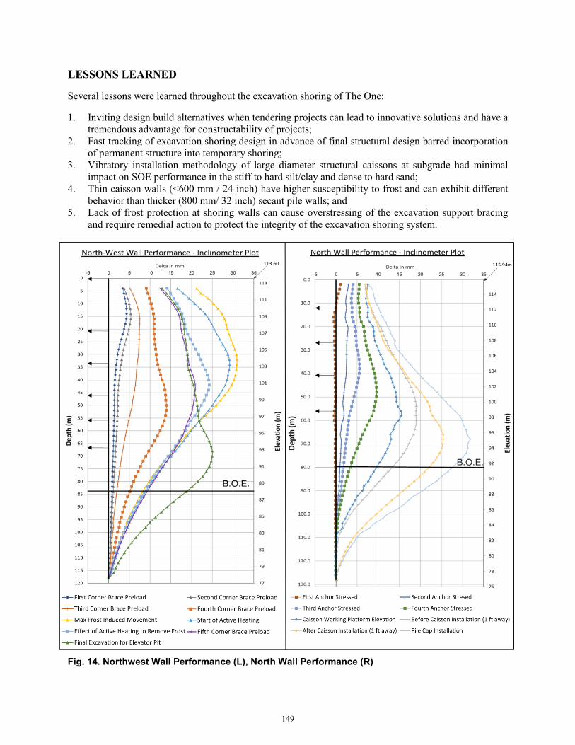
Prior to November 1 at The One, frost protection was installed on the micropile shoring wall only which showed little to no impact from frost throughout the winter. In our experience, frost traditionally develops from the top of the excavation downwards - a trend that was visible on the East wall of the project. However, the SOE system at The One posed an additional challenge for frost susceptibility: the “skinny” caissons walls on the Northwest and South walls. These 570 mm (22 ½” inch) walls were the first to show impact from frost and exhibited movement over the entire depth of the excavation. This difference in expected behavior of frost loading resulted in delay of problem identification and required remedial action to protect the integrity of the shoring. Insulated blankets and active heating were required on the Northwest and East walls, and the South wall was backfilled with a 7 m (23 ft) berm to the third tieback level to protect the anchors from yielding. The total additional movement due to frost ranged from 12 mm (1/2”) on the Northwest wall to 20 mm (3/4”) on the South wall. After active heating, frost induced movement was recovered on the North and East walls, and movement was recovered on the South wall after temperatures rose above 0°C. Frost movement had little to no impact on the North (i.e. South – facing) wall which receives the most sun exposure. SHORING PERFORMANCE Figures 11 – 14 below show overall SOE performance at the North wall, South wall, “Superpile”, and West wall. With the exception of frost induced movement, shoring performed within expectations and vibratory installation methods had minimal impact on overall shoring performance.
148
LESSONS LEARNED
Several lessons were learned throughout the excavation shoring of The One:
1. Inviting design build alternatives when tendering projects can lead to innovative solutions and have a tremendous advantage for constructability of projects;
2. Fast tracking of excavation shoring design in advance of final structural design barred incorporation of permanent structure into temporary shoring;
3. Vibratory installation methodology of large diameter structural caissons at subgrade had minimal impact on SOE performance in the stiff to hard silt/clay and dense to hard sand;
4. Thin caisson walls (<600 mm / 24 inch) have higher susceptibility to frost and can exhibit different behavior than thicker (800 mm/ 32 inch) secant pile walls; and
5. Lack of frost protection at shoring walls can cause overstressing of the excavation support bracing and require remedial action to protect the integrity of the excavation shoring system.
Fig. 14. Northwest Wall Performance (L), North Wall Performance (R)
149

Fig. 15. South Wall Performance (L), Superpile Performance (R)
ACKNOWLEDGEMENTS
To Mizrahi and Clark Construction Management for undertaking Toronto’s first supertall residence.
REFERENCES
1. Terraprobe, 2016. Detailed Geotechnical Investigation, The One, 1 Bloor Street West, Toronto, Ontario. 60 p.
2. APE, 2007. American Pile Driving Equipment Inc. Model 400 Vibratory Driver Extractor. http://www.americanpiledriving.com/manuals/APE/400_1050_11%2007_Spec.pdf. 2 p. Accessed 19.04.01.
*Backfilling against South wall up to Third Row Anchors occurred Feb 8
150