Innovations 2014/2015 au
105
www.ifm.com Innovations 2014/2015 years W A R R A N T Y o n i f m p r o d u c t s
-
Upload
ifm-electronic-gmbh -
Category
Documents
-
view
133 -
download
4
Transcript of Innovations 2014/2015 au

ww
w.if
m.c
om
Innovations 2014/2015
years
W
ARRANTY
on ifm products


3
TOP
PRO
DU
CTS
3D Smart Sensor – your assistant on mobile machinesTrue 3D vision sensorRobust camera system O2M for mobile machines
Camera systems for mobile machines
(11.2014)
(11.2014)
(04.2014)
Industrial imaging
See what is going on. Capacitive sensor for more transparency
Capacitive sensors
Photoelectric sensors for general applications
Powerful photoelectric sensors in a plastic housingHigh-performance “O6 wetline” photoelectric sensors“O6 wetline” now with IO-Link
(04.2014)
(04.2014)
(11.2014)
(11.2014)
Position sensors
Laser sensors / distance measurement sensors
O5D – first standard photocell with time of flight measurement (PMD)PMD O5D – Now also with laser class 1OID with time of flight measurement (PMD) and easy-turnOID with time of flight measurement (PMD) and easy-turn, laser class 1
(04.2014)
(11.2014)
(04.2014)
(11.2014)
Temperature sensors
Small but effective: temperature transmitter in compact housingRobust infrared temperature sensors for hot objectsTemperature transmitter with display and IO-Link
(04.2014)
(04.2014)
(04.2014)
Process sensors
Hygienic point level sensor perfectly suppresses deposits (04.2014)
Level sensors
Precision for all inclinations
Inclination sensors
(04.2014)
Sensors for motion control
Pressure sensors
Pressure transmitters PU for mobile applicationsSmall and cost-optimised: PT / PU pressure transmittersAn update for the bestseller: PN pressure sensor with a new look
(11.2014)
(04.2014)
(11.2014)
XL dialogue module PDM360 NG-12 for mobile machines
Dialogue modules / displays
(11.2014)
Systems for mobile machines
4 - 5
6 - 910 - 1314 - 15
16 - 1718 - 1920 - 2122 - 23
26 - 2728 - 2930 - 31
40 - 4142 - 4344 - 45
38- 39
24 - 25
32 - 3334 - 3536 - 37
46 - 47

4
Position sensors
Precise evaluation of the application by visualisation of the process
See what the sensor is seeingAt last it is possible to integrate process values into theIT structure via an intelligent sensor interface and foreasier indication, analysis and evaluation. The application becomes transparent, and the processvalue allows effective further processing. At present thisadditional advantage is unique and offers solutionseven for difficult applications.
ApplicationCapacitive sensors detect bulk materials or liquidsthrough non-metallic vessel walls. Typical applicationsfor product detection can be found in the semiconduc-tor, paper and wood industries.
Parameter settingThe parameters can either be set via the buttons on thesensor or via IO-Link interface. This can be done usingthe USB interface E30396 or a memory plug E30398.The LINERECORDER SENSOR software also simplifiesthe monitoring of different types of sensors.
Easy parameter setting via IO-Link beforeinstallation of the sensor
Versatile data processing via IO-Link
No new cabling necessary
Clearly visible indication of the switchingstatus
Easy installation with mounting adaptersand cable ties
See what is going on! Capacitivesensor for more transparency

5
(11.2014)
TOP
PRO
DU
CTS
For further technical data please go to: www.ifm.com
Position sensorsCapacitive sensors
Type Description Order no.
Accessories
Mounting adapter for free-standing mounting, PBT E12153
Mounting adapter for pipe and tubemounting with cable ties, PA E12163
Connection technology
Type Description Order no.
M12 socket,2 m black, PUR cable EVC001
M8 socket,2 m black, PUR cable EVC150
* automatic detection of the load
Memory plug, parameter memory for IO-Link sensors E30398
IO-Link interface, current consumption from USB port E30396
LINERECORDER SENSOR,software for parameter setting and set-up of IO-Link sensors
ZGS210
Type
[mm]
Output stage
Housing material Protection rating / class
Order no.
Connection cable 2 m PVC· 3 wires
M18 x 1 PNP PP, TPE-U IP 65, IP 67, II KG5069
Connection cable with M8 connector · 3 wires
48 x 20 x 14 PNP PBT, PC, TPE-U IP 65, IP 67, III KQ6004
Connection cable with M12 connector · 3-wire
48 x 20 x 14 PNP
Setting range[mm]
2...14
3...20
48 x 20 x 14 PNP PBT, PC, TPE-U IP 65, IP 67, III KQ60083...20
Communicationinterface
IO-Link 1.1
48 x 20 x 14 PNP PBT, PC, TPE-U IP 65, IP 67, III KQ60023...20 IO-Link 1.1
M12 connector · 3 wires
M18 x 1 PNP / NPN* PBT, PC, TPE-U IP 65, IP 67, II KG5065
M18 x 1 PNP PBT, PC, TPE-U IP 65, IP 67, II KG5066
4...24
4...24
IO-Link 1.1
IO-Link 1.1
M18 x 1 PNP PBT, PC, TPE-U IP 65, IP 67, II KG5071
M30 x 1.5 PNP / NPN* PBT, PC, TPE-U IP 65, IP 67, II KI5082
2...14
5...40
IO-Link 1.1
IO-Link 1.1
M30 x 1.5 PNP PBT, PC, TPE-U IP 65, IP 67, II KI5083
M30 x 1.5 PNP / NPN* high-grade stainless steel(1.4404), TPE-U, PBT, PEI IP 65, IP 67, III KI5084
5...40
2...12
IO-Link 1.1
IO-Link 1.1
M30 x 1.5 PNP high-grade stainless steel(1.4404), TPE-U, PBT, PEI IP 65, IP 67, III KI5085
M30 x 1.5 PNP / NPN* high-grade stainless steel(1.4404), TPE-U, PBT, PEI IP 65, IP 67, III KI5086
2...12
3...26
IO-Link 1.1
IO-Link 1.1
M30 x 1.5 PNP high-grade stainless steel(1.4404), TPE-U, PBT, PEI IP 65, IP 67, III KI50873...26 IO-Link 1.1
IO-Link 1.1
IO-Link 1.1
IO-Link 1.1
3...20 PBT, PC, TPE-U IP 65, IP 67, III KQ6005
Type Description Order no.
Plastic housing, 24 V DC, 2.5 A DN1031
Power supplies
Accessories
48 x 20 x 7 PNP PBT, TPE-U IP 65, IP 67, III KQ51003...20 IO-Link 1.1
48 x 20 x 7 IO-Link 1.1PNP PBT, TPE-U IP 65, IP 67, III
KQ5101
3...20
48 x 20 x 7 PNP IO-Link 1.13...20 PBT, TPE-U IP 65, IP 67, III
KQ5102

6
Powerful photoelectric sensors in a plastic housing
Best optical performanceThe diffuse reflection sensors provide reliable back-ground suppression, even in case of highly reflectivebackgrounds such as moving machine parts. The clearlydefined consistent light spot ensures precise object de-tection. There is no scattered light which could interferewith other photoelectric sensors in close vicinity.
Ideal for universal applicationsFor connection the user can choose between pottedcable, M12 pigtail or M8 metal connector on the housing.The range can be set intuitively via potentiometer.Light-on or dark-on mode is selected via rotary switch.Furthermore, the plug & play versions are available withfixed setting, without operating elements. The diffusereflection, through-beam and retro-reflective sensorsare distinguished by an excellent price /performanceratio. An extensive range of accessories completes theifm range.
Diffuse reflection sensors with reliablebackground suppression
Intuitive setting via potentiometer or rotary switch; or fixed setting
Well-defined light spot for precise objectdetection, no scattered light
Also available as through-beam or retro-reflective system
Versions with M8 connector, M12 pigtailor PUR connection cable
O6 miniature photoelectric sensors with high-performance
Position sensors

7
TOP
PRO
DU
CTS
Infrared sensors / red light sensorsPosition sensors
* at maximum range** referred to prismatic reflector Ø 80 mm
Dimensions
L+
L
1
4
3
Wiring diagram
L+
L
1
4
3
BN
BK
BU
L+
L L
BN
BK
BU
L+
L+
L
BN
BU
1
3
L+
L
Diffuse reflection sensor with background suppression · 3-wire DC
Light spot diameter
[mm]
Connection Order no.
8* O6H200
Range
[mm]
2...200 PUR cable, 2 m
Order no.
O6H204
PNPNPN
8* O6H2012...200 M12 connector with 0.3 m PUR cable O6H205
Diffuse reflection sensor · 3-wire DC
15* O6T2005...500 PUR cable, 2 m O6T204
PNPNPN
15* O6T2015...500 M12 connector with 0.3 m PUR cable O6T205
Retro-reflective sensor with polarisation filter · 3-wire DC
150** O6P20050...5000 PUR cable, 2 m O6P204
PNPNPN
150** O6P20150...5000 M12 connector with 0.3 m PUR cable O6P205
Through-beam sensor transmitter · 2-wire DC
300*0...10000 PUR cable, 2 m O6S200
300*0...10000 M12 connector with 0.3 m PUR cable O6S201
Through-beam sensor receiver · 3-wire DC
– O6E2000...10000 PUR cable, 2 m O6E204
PNPNPN
– O6E2010...10000 M12 connector with 0.3 m PUR cable O6E205
Current consumption
[mA]
22
22
16
16
12
12
11
11
7
7
2 x LED
1321
35,4
25,4
3,4
3
M3
1) Switch output function2) Potentiometer sensitivity

8
Position sensors
Dimensions
L+
L
1
4
3
Wiring diagram
L+
L
1
4
3
1
3
L+
L
* at maximum range** referred to prismatic reflector Ø 80 mm
Diffuse reflection sensor with background suppression · 3-wire DC
Light spot diameter
[mm]
Connection Order no.
8* O6H202
Range
[mm]
2...200 M8 connector, 3-pole
Light-on / dark-on mode Order no.
O6H206
PNPNPN
8* O6H2032...200 M8 connector, 4-pole O6H207
Diffuse reflection sensor · 3-wire DC
15* O6T2025...500 M8 connector, 3-pole O6T206
PNPNPN
15* O6T2035...500 M8 connector, 4-pole O6T207
Retro-reflective sensor with polarisation filter · 3-wire DC
150** O6P20250...5000 M8 connector, 3-pole O6P206
PNPNPN
150** O6P20350...5000 M8 connector, 4-pole O6P207
Through-beam sensor transmitter · 2-wire DC
300*0...10000 M8 connector, 3-pole O6S202
300*0...10000 M8 connector, 4-pole O6S203
Through-beam sensor receiver · 3-wire DC
– O6E2020...10000 M8 connector, 3-pole O6E206
PNPNPN
– O6E2030...10000 M8 connector, 4-pole O6E207
• / •adjustable
• / •adjustable
• / •adjustable
• / •adjustable
• / •adjustable
• / •adjustable
– / –
– / –
• / •adjustable
• / •adjustable
2 x LED
M8x1
1321
35,4
25,4
3,4
3
46
M3
1) Switch output function2) Potentiometer sensitivity
4
L
L+1
2
32:4:
Diffuse reflection sensor with background suppression · 4-wire DC
8* O6H211100fixed setting
M8 connector, 4-pole
• / –fixed setting O6H213
PNPNPN
8* O6H212200fixed setting
M8 connector, 4-pole
• / –fixed setting O6H214
8* O6H2102...200 M8 connector, 4-pole
• / •complementary –

9
(04.2014)
TOP
PRO
DU
CTS
For further technical data please go to: www.ifm.com
Infrared sensors / red light sensorsPosition sensors
Common technical data
Operating voltage [V DC] 10...30
Type of light red light 633 nm
Switching status indication LED yellow
Indication of stable operation LED green
Short-circuit protection, pulsed •
Reverse polarity protection / overloadprotection • / •
Ambient temperature [°C] -25...60
Voltage drop [V] < 2.5
Current rating [mA] 100
Accessories
Type Description Order no.
Mounting set for clamp mounting,stainless steel, Ø 10 mm E21272
Mounting set for clamp mounting,stainless steel, Ø 12 mm E21275
Bracket for free-standing mounting,stainless steel E21271
Protective bracket,stainless steel E21273
Materials housing
lens
ABS
PMMA
Connection technology
Type Description Order no.
Mounting rod, 120 mm, Ø 10 mm, M8 thread, stainless steel E21081
Mounting rod, 100 mm, Ø 12 mm, M10 thread, stainless steel E20938
Switching frequency [Hz] 1000
Protection rating, class
IP 65 / IP 67, III
Socket, M8, 4-pole,2 m black, PUR cable EVC150
Socket, M8, 4-pole,5 m black, PUR cable EVC151
Socket, M8, 3-pole,2 m black, PUR cable EVC144
Socket, M8, 3-pole,5 m black, PUR cable EVC145
Socket, M8, 3-pole,2 m black, PUR cable EVC141
Socket, M8, 3-pole,5 m black, PUR cable EVC142
Socket, M12,2 m black, PUR cable EVC001
Socket, M12,5 m black, PUR cable EVC002
Socket, M8, 4-pole,2 m black, PUR cable EVC153
Socket, M8, 4-pole,5 m black, PUR cable EVC154
Ø 50 mm, plastic E20956
Ø 80 mm, plastic E20005
48 x 48 mm, PMMA, ABS E20744
95 x 95 mm, plastic E20454
Prismatic reflector
Cube for mounting on an aluminiumprofile, M8 thread, diecast zinc E20950
Cube for mounting on an aluminiumprofile, M10 thread, diecast zinc E20951
Mounting accessories
Plastic housing, 24 V DC, 2.5 A DN1031
Metal housing, 24 V DC, 3.3 A DN4011
Power supplies
Pinhole mask for through-beam sensors, Ø 0.5 mm E21277
Slot mask for through-beam sensors, 0.5 x 8 mm E21280

10
Powerful and robust sensorsfor the food industry
Best optical performanceThe diffuse reflection sensors distinguish themselves byreliable background suppression, even in case of highlyreflective backgrounds. The sensing range is independentof the characteristics and colour of the object to be detected. A special feature is the automatic sensitivitycompensation that guarantees reliable operation evenin steam, smoke or highly reflective environments.In addition to versions with switching output, versionswith complementary switching outputs are now alsoavailable.
Ideal for food applicationsThe potentiometers are provided with a double sealand are, like the front pane, embedded flush to allowresidue-free cleaning. The transparent black housingcover ensures that, even in bright lighting conditions,the LEDs are highly visible. The coated front pane ismade of resistant, shatterproof plastic.
Stainless steel housing with protection rating IP 68 / IP 69K
Easy setting of the range via potentiometer
Diffuse reflection sensors with reliablebackground suppression
Object colour has no influence on therange
Now also with complementary switching outputs
O6 WetLine miniature high-performance photoelectric sensors
Position sensors

11
TOP
PRO
DU
CTS
Infrared sensors / red light sensorsPosition sensors
Dimensions
2 x LED
1321
34,8
25,4
3,4
3
M3
19,5
L+
L
1
4
3
Wiring diagram
L+
L
1
4
3
BN
BK
BU
L+
L L
BN
BK
BU
L+
L+
L
BN
BU
1
3
L+
L
Diffuse reflection sensor with background suppression · 3-wire DC
Light spot diameter
[mm]
Connection Order no.
8*
Range
[mm]
2...200 PVC cable, 2 m
Order no.
PNPNPN
8*2...200 M12 connector with 0.3 m PVC cable
Diffuse reflection sensor · 3-wire DC
15*5...500 PVC cable, 2 m
PNPNPN
15*5...500 M12 connector with 0.3 m PVC cable
Retro-reflective sensor with polarisation filter · 3-wire DC
150**50...5000 PVC cable, 2 m
PNPNPN
150**50...5000 M12 connector with 0.3 m PVC cable
Through-beam sensor transmitter · 2-wire DC
300*0...10000 PVC cable, 2 m
300*0...10000 M12 connector with 0.3 m PVC cable
Through-beam sensor receiver · 3-wire DC
–0...10000 PVC cable, 2 m
PNPNPN
–0...10000 M12 connector with 0.3 m PVC cable
* at maximum range** referred to prismatic reflector Ø 80 mm
Current consumption
[mA]
22
22
16
16
12
12
11
11
7
7
1) Switch output function2) Potentiometer sensitivity
O6H300O6H304
O6H301O6H305
O6T300O6T304
O6T301O6T305
O6P300O6P304
O6P301O6P305
O6S300
O6S301
O6E300O6E304
O6E301O6E305

12
Position sensors
Dimensions
2 x LED
M8x1
1321
34,8
25,4
2,8
3
41,3
M3
L+
L
1
4
3
Wiring diagram
L+
L
1
4
3
1
3
L+
L
* at maximum range** referred to prismatic reflector Ø 80 mm
Diffuse reflection sensor with background suppression · 3-wire DC
Light spot diameter
[mm]
Connection Order no.
8* O6H302
Range
[mm]
2...200 M8 connector, 3-pole
Order no.
O6H306
PNPNPN
8* O6H3032...200 M8 connector, 4-pole O6H307
Diffuse reflection sensor · 3-wire DC
15* O6T3025...500 M8 connector, 3-pole O6T306
PNPNPN
15* O6T3035...500 M8 connector, 4-pole O6T307
Retro-reflective sensor with polarisation filter · 3-wire DC
150** O6P30250...5000 M8 connector, 3-pole O6P306
PNPNPN
150** O6P30350...5000 M8 connector, 4-pole O6P307
Through-beam sensor transmitter · 2-wire DC
300*0...10000 M8 connector, 3-pole O6S302
300*0...10000 M8 connector, 4-pole O6S303
Through-beam sensor receiver · 3-wire DC
– O6E3020...10000 M8 connector, 3-pole O6E306
PNPNPN
– O6E3030...10000 M8 connector, 4-pole O6E307
Light-on / dark-on mode
• / •adjustable
• / •adjustable22
• / •adjustable
• / •adjustable
• / •adjustable
• / •adjustable
– / –
– / –
• / •adjustable
• / •adjustable
1) Switch output function2) Potentiometer sensitivity
Diffuse reflection sensor with background suppression · 4-wire DC
8* O6H3102...200 M8 connector, 4-pole –
PNPNPN
• / •complementary
Retro-reflective sensor with polarisation filter · 3-wire DC
150** O6P31050...5000 M8 connector, 4-pole –
PNPNPN
• / •complementary
4
L
L+1
2
32:4:

13
(04.2014)
TOP
PRO
DU
CTS
For further technical data please go to: www.ifm.com
Infrared sensors / red light sensorsPosition sensors
Common technical data
Operating voltage [V DC] 10...30
Type of light red light 633 nm
Short-circuit protection, pulsed •
Reverse polarity protection / overloadprotection • / •
Ambient temperature [°C] -25...80
Accessories
Type Description Order no.
Mounting set for clamp mounting,stainless steel E21272
Bracket for free-standing mounting,stainless steel E21271
Protective bracket,stainless steel E21273
18 x 18 mm, Solidchem plastic E21267
56 x 38 mm, Solidchem plastic E21268
48 x 48 mm, Solidchem plastic E21269
96 x 96 mm, Solidchem plastic E21270
Materials housing
lens
high-grade stainless steel(1.4404 / 316L)
PPSU PMMA
Prismatic reflectors for the food industry (up to 140 °C)
Connection technology
Type Description Order no.
Socket, M8, 3-pole,2 m orange, PVC cable EVT122
Socket, M8, 3-pole,5 m orange, PVC cable EVT123
Socket, M8, 3-pole,2 m orange, PVC cable EVT126
Socket, M8, 3-pole,5 m orange, PVC cable EVT127
Socket, M8, 3-pole,2 m orange, PVC cable, LED EVT130
Socket, M8, 3-pole,5 m orange, PVC cable, LED EVT131
Mounting rod, 120 mm, Ø 10 mm, M8 thread, stainless steel E21081
Angle bracket for reflector E21269, stainless steel E20724
Mounting set for reflector E21270, clamp mounting, stainless steel E20935
Socket, M12, 4-pole,5 m orange, PVC cable EVT001
Socket, M12, 4-pole,2 m orange, PVC cable EVT064
Switching status indication LED yellow
Operation LED green
Voltage drop [V] < 2.5
Current rating [mA] 100
Switching frequency [Hz] 1000
Mounting accessories
Plastic housing, 24 V DC, 2.5 A DN1031
Metal housing, 24 V DC, 3.3 A DN4011
Power supplies
Protection rating, class
IP 65, IP 67, IP 68, IP 69K,III
Socket, M8,4-pole,2 m orange, PVC cable EVT138
Socket, M8, 4-pole,5 m orange, PVC cable EVT139

14
Small and compact photoelectric sensors nowalso as IO-Link versions!
Best performanceThe diffuse reflection sensors distinguish themselves byreliable background suppression, even in case of highlyreflective backgrounds. A special feature is the automatic switch point adjustment that guarantees reliable operation even in steam, smoke or highly reflective environments. The wetline series features a particularly robust stainlesssteel housing with protection rating IP 68 / IP 69K. The potentiometer with double sealing ensures maximum ingress resistance. The flush front lens ensures cleaningwithout residues.
IO-LinkThe O6 wetline sensors are now also available as versions with IO-Link. Via this interface, the user can set range,sensitivity, light-on / dark-on mode, switching delay ordeactivation of the operating elements.
Stainless steel housing with protection rating IP 68 / IP 69K
Diffuse reflection sensors with reliablebackground suppression
Well-defined light spot for precise objectdetection, no scattered light
Also available as through-beam or retro-reflective system
Many functions can be set via IO-Link,e.g. range and sensitivity
O6 wetline now with IO-Link!
Position sensors

15
(11.2014)
TOP
PRO
DU
CTS
Infrared sensors / red light sensorsPosition sensors
For further technical details please visit: www.ifm.com
Diffuse reflection sensor with background suppression · 3-wire DC · PNP
Light spot diameter
[mm]
Connection M8 connector
Order no.
8* O6H309
Range
[mm]
2...200 4-pole
Current consumption
[mA]
22
Diffuse reflection sensor · 3-wire DC · PNP
15* O6T3095...500 4-pole 16
Retro-reflective sensor with polarisation filter · 3-wire DC · PNP
150** O6P30950...5000 4-pole 12
Through-beam sensor - transmitter · 2-wire DC
300*0...10000 4-pole 11 O6S305
Through-beam sensor – receiver · 3-wire DC · PNP
– O6E3090...10000 4-pole 7
Communication interface
IO-Link 1.1
IO-Link 1.1
IO-Link 1.1
IO-Link 1.1
IO-Link 1.1
* at maximum range** referred to prismatic reflector Ø 80 mm
Accessories
Type Description Order no.
Mounting set for clamp mounting, stainless steel, Ø 10 mm E21272
Angle bracket for free-standing mounting, stainless steel E21271
Rod, 120 mm, Ø 10 mm, M8 thread, stainless steel E21081
Memory plug, parameter memoryfor IO-Link sensors E30398
IO-Link interface, current consumptionfrom USB port E30396
LINERECORDER SENSOR,software for parameter setting and set-up of IO-Link sensors
ZGS210
Common technical data
Operating voltage [V DC] 10...30
Type of light red light 633 nm
Switching status indication LED yellow
Operation LED green
Short-circuit protection, pulsed •
Reverse polarity protection / overload protection • / •
Ambient temperature [°C] -25...80
Voltage drop [V] < 2.5
Current rating [mA] 100
Materials housing
lens
high-grade stainless steel(316L/1.4404), PPSU
PMMA
Connection technology
Type Description Order no.
M8 socket, 4-pole,2 m orange, PVC cable EVT122
M8 socket, 4-pole,5 m orange, PVC cable EVT123
M8 socket, 4-pole,2 m orange, PVC cable EVT126
M8 socket, 4-pole,5 m orange, PVC cable EVT127
Adapter cable M12 plug to M8 socket 4-pole, 0.3 m orange, PVC cable
EVT248
Switching frequency [Hz] 1000
Protection rating, protection class
IP 65, IP 67, IP 68, IP 69K,III
Light-on / dark-on mode adjustable
18 x 18 mm, Solidchem plastic E21267
56 x 38 mm, Solidchem plastic E21268
48 x 48 mm, Solidchem plastic E21269
96 x 96 mm, Solidchem plastic E21270

16
O5D with display – first standard photocell with timeof flight measurement (PMD)
Time of flight measurement for standard sensorsThe O5D with time of flight measurement (PMD = photonic mixer device) combines the following advan-tages: long ranges, reliable background suppression, visible red light and high excess gain. In the same pricerange as standard sensors, it is a clever alternative.
Easy handlingThe switch point is set easily to the nearest centimetrevia “+/-” buttons and display or alternatively via IO-Link, which also allows read-out of the actual value.
Any surface and any mounting positionShiny, matt, dark or light objects of any colour: the O5D features reliable background suppression. The unit allows any angle of incidence and thus flexible mountingpositions. This simplifies installation and saves costs.
Reliable background suppression and colour-independent detection
Precise time of flight measurement in hous-ing sizes of standard photoelectric sensors
Shiny surfaces are detected reliably (e.g. stainless steel)
Any sensor position, even an obliqueangle to the object
Switch point setting to the nearest centimetre via “+/-” buttons and display
PMDLine series – a new generationof photoelectric sensors
Position sensors

17
(04.2014)
TOP
PRO
DU
CTS
For further technical data please go to: www.ifm.com
Laser sensors / distance measurement sensors
Common technical data
Operating voltage [V DC] 10...30
Dimensions [mm] 56 x 18,2 x 46,5
Type of light visible laser light 650 nm
Extraneous light on the object [klx] max. 8
Switching status indication LED yellow
Operation LED green
Distance value3-digit
alphanumeric display
Protection rating, protection class
IP 65,IP 67II
Short-circuit protection, pulsed •
Reverse polarity protection / overload protection • / •
Ambient temperature [°C] -25...60
Current rating [mA] 2 x 100
Output function OUT1: NOOUT2: NC
Position sensors
Connection technology
Type Description Order no.
Socket, M12,2 m black, PUR cable EVC001
Socket, M12,5 m black, PUR cable EVC002
Socket, M12,2 m black, PUR cable EVC004
Socket, M12,5 m black, PUR cable EVC005
Photoelectric distance sensor, laser protection class 2 · M12 connector, complementary
30...2000 < 5 < 75 O5D101
30...2000 O5D100< 5 < 75 cm
inch
Material housing / plug adapterfront pane / LED window
bezeloperator interface
PAPMMA
stainless steelTPU
Accessories
Type Description Order no.
Mounting bracket for rod,complete set incl. clamp E21083
Protective bracket for rod,complete set incl. clamp E21084
Bracket for free-standing mounting E21087
Cube for mounting on an aluminiumprofile, M10 thread, diecast zinc E20951
Measuringrange[mm]
Backgroundsuppression
[m]
Switching frequency
[Hz]
Spot Ø at max. range
[mm]
Current consumption
[mA]
Order no.
Unit of measurement
Hysteresis
[%]
Memory plug, parameter memory for IO-Link sensors E30398
IO-Link interface, current consumption from USB port E30396
LINERECORDER SENSOR, software for parameter setting and set-up of IO-Link sensors
ZGS210
* in case of max. range
...20 11
...20 11
< 2.5...4*
< 2.5...4*
PNP
Photoelectric distance sensor, laser protection class 2 · M12 connector, complementary NPN
30...2000 ...20 O5D10211 < 5 < 75 cm< 2.5...4*
Hysteresis
x: Distance in [mm], y: Hysteresis in [mm]1. Background black (6 % remission)2. Background white (90 % remission)

18
PMD O5D – Now also withlaser class 1
Time of flight measurement for standard sensorsThe O5D with time of flight measurement (PMD = photonic mixer device) combines the advantages oflong range, reliable background suppression, visible redlight, high excess gain and laser class 1.This makes it a clever alternative to standard sensors,which are equal in price and size.
Easy handlingThe switch point is easily and precisely set via “+/-” buttons and display or IO-Link, which also allows read-out of the actual value.
Any surface and any mounting positionShiny, matt, dark or light objects of any colour: the O5D features reliable background suppression. The unitallows any angle of incidence of the transmitted lightand thus any mounting position.
Precise time of flight measurement (PMD)in a compact housing
Reliable background suppression and colour-independent detection
Shiny surfaces are detected reliably (e.g. stainless steel)
Switch point setting to the nearest centimetre via “+/-” buttons and display
Laser class 1 – for more universal application
First class PMDLine!
Position sensors

19
(11.2014)
TOP
PRO
DU
CTS
For further technical data please go to: www.ifm.com
Laser sensors / distance measurement sensors
Common technical data
Operating voltage [V DC] 10...30
Dimensions [mm] 56 x 18,2 x 46,5
Type of light visible laser light 650 nm
Extraneous light on the object [klx] max. 8
Switching status indication LED yellow
Operation LED green
Distance value3-digit
alphanumeric display
Protection rating, protection class
IP 65,IP 67III
Short-circuit protection, pulsed •
Reverse polarity protection / overload protection • / •
Ambient temperature [°C] -25...60
Current rating [mA] 2 x 100
Output function OUT1: NOOUT2: NC
Position sensors
Connection technology
Type Description Order no.
Socket, M12,2 m black, PUR cable EVC001
Socket, M12,5 m black, PUR cable EVC002
Socket, M12,2 m black, PUR cable EVC004
Socket, M12,5 m black, PUR cable EVC005
Photoelectric distance sensor, laser protection class 1 · M12 connector, complementary
Material housing / plug adapterfront pane / LED window
bezeloperator interface
PAPMMA
stainless steelTPU
Accessories
Type Description Order no.
Mounting bracket for rod,complete set incl. clamp E21083
Protective bracket for rod,complete set incl. clamp E21084
Bracket for free-standing mounting E21087
Dovetail clamp E21088
Rod, 100 mm, Ø 12 mm,M10 thread, stainless steel E20938
Cube for mounting on an aluminiumprofile, M10 thread, diecast zinc E20951
Measuringrange[mm]
Backgroundsuppression
[m]
Switching frequency
[Hz]
Spot Ø at max. range
[mm]
Current consumption
[mA]
Order no.
Unit of measurement
Hysteresis
[%]
Memory plug, parameter memory for IO-Link sensors E30398
IO-Link interface, current consumption from USB port E30396
LINERECORDER SENSOR, software for parameter setting and set-up of IO-Link sensors
ZGS210
* in case of max. range
Metal housing, 24 V DC, 3.3 A DN4011
Power supplies
Type Description Order no.
30...2000 ...20 11 < 5 < 75 O5D151
30...2000 ...20 O5D15011 < 5 < 75 cm
inch< 7.5*
< 7.5*
PNP

20
OID with easy-turn concept –photoelectric sensor with timeof flight measurement (PMD)
Time of flight measurement for standard sensorsThe OID with time of flight measurement (PMD = photonic mixer device) combines the following advan-tages: long ranges, reliable background suppression, visible red light and high excess gain. In the same pricerange as standard sensors, it is a clever alternative.
Easy handlingThe switch point can be set easily by turning the settingring (easy turn). A scale shows the distance set. Theswitch point can thus be set before installation.
Any surface and any mounting positionShiny, matt, dark or light objects of any colour: the OID features reliable background suppression. The unit allows any angle of incidence and thus flexible mountingpositions. This simplifies installation and saves costs.
Reliable background suppression and colour-independent detection
Simple switch point setting by rotatablesetting ring (lock function)
Shiny surfaces are detected reliably (e.g. stainless steel)
Any sensor position, even an obliqueangle to the object
IO-Link integrated, e.g. for reading theactual value
PMDLine M30: This photoelectricsensor is all set
Position sensors

21
(04.2014)
TOP
PRO
DU
CTS
For further technical data please go to: www.ifm.com
Laser sensors / distance measurement sensors
Common technical data
Operating voltage [V DC] 10...30
Dimensions M30 x 90 mm
Type of light visible laser light 650 nm
Extraneous light on the object [klx] max. 8
Switching status indication LED yellow
Operation LED green
Switch point (setting) radial setting ring
Protection rating, protection class
IP 65,IP 67III
Short-circuit protection, pulsed •
Reverse polarity protection / overload protection • / •
Ambient temperature [°C] -25...60
Current rating [mA] 2 x 100
Output function OUT1: NOOUT2: NC
Position sensors
Connection technology
Type Description Order no.
Socket, M12,2 m black, PUR cable EVC001
Socket, M12,5 m black, PUR cable EVC002
Socket, M12,2 m black, PUR cable EVC004
Socket, M12,5 m black, PUR cable EVC005
Photoelectric distance sensor, laser protection class 2 · M12 connector, complementary
Measuringrange[mm]
Backgroundsuppression
[m]
Switching frequency
[Hz]
Spot Ø at max. range
[mm]
Current consumption
[mA]
Order no.
Unit of measurement
Hysteresis
[%]
Material housing
front pane
stainless steel, PBT, PC, FPM
PMMA
Cube for mounting on an aluminiumprofile, M10 thread, diecast zinc E20951
Type Description Order no.
Accessories
Angle bracket for type M30,stainless steel E10737
Mounting clamp for types M30, PTB E10077
Mounting clamp, with end stop for types M30, PC E11049
Memory plug, parameter memory for IO-Link sensors E30398
IO-Link interface, current consumption from USB port E30396
LINERECORDER SENSOR, software for parameter setting and set-up of IO-Link sensors
ZGS210
30...2000 < 5 < 75 OID201
30...2000 OID200< 5 < 75 cm / inch
cm
* in case of max. range
...20 11
...20 11
< 1.5...3*
< 1.5...3*
Photoelectric distance sensor, laser protection class 2 · M12 connector, complementary NPN
30...2000 ...20 OID20211 < 5 < 75 cm< 1.5...3*
PNP
Hysteresis
x: Distance in [mm], y: Hysteresis in [mm]1. Background black (6 % remission)2. Background white (90 % remission)

22
Photoelectric sensor with time of flight measurement (PMD),easy-turn concept, laser class 1
Time of flight measurement for standard sensorsThe OID with time of flight measurement (PMD = photonic mixer device) combines the following advan-tages: long ranges, reliable background suppression, visible red light, high excess gain and now also laserclass 1. In the same price range as standard sensors, it is a clever alternative.
Easy handlingThe switch point can be set easily by turning the settingring (easy turn, lock function). A scale shows the distance set. The switch point can thus be set before installation.
Any surface and any mounting positionShiny, matt, dark or light objects of any colour: the OID features reliable background suppression. The unit allows any angle of incidence and thus flexible mountingpositions. This simplifies installation and saves costs.
Reliable background suppression and colour-independent detection
Simple switch point setting by rotatablesetting ring (lock function)
Shiny surfaces are detected reliably (e.g. stainless steel)
Any sensor position, even an obliqueangle to the object
Laser class 1 – for more universal application
PMDLine M30: Now also with laser class 1
Position sensors

23
(11.2014)
TOP
PRO
DU
CTS
For further technical data please go to: www.ifm.com
Laser sensors / distance measurement sensors
Common technical data
Operating voltage [V DC] 10...30
Dimensions M30 x 90 mm
Type of light visible laser light 650 nm
Extraneous light on the object [klx] max. 8
Switching status indication LED yellow
Operation LED green
Switch point (setting) radial setting ring
Protection rating, protection class
IP 65,IP 67III
Short-circuit protection, pulsed •
Reverse polarity protection / overload protection • / •
Ambient temperature [°C] -25...60
Current rating [mA] 2 x 100
Output function OUT1: NOOUT2: NC
Position sensors
Connection technology
Type Description Order no.
Socket, M12,2 m black, PUR cable EVC001
Socket, M12,5 m black, PUR cable EVC002
Socket, M12,2 m black, PUR cable EVC004
Socket, M12,5 m black, PUR cable EVC005
Photoelectric distance sensor, laser protection class 1 · M12 connector, complementary
Measuringrange[mm]
Backgroundsuppression
[m]
Switching frequency
[Hz]
Spot Ø at max. range
[mm]
Current consumption
[mA]
Order no.
Unit of measurement
Hysteresis
[%]
Material housing
front pane
stainless steel, PBT, PC, FPM
PMMA
Rod, 100 mm, Ø 12 mm,M10 thread, stainless steel E20938
Cube for mounting on an aluminiumprofile, M10 thread, diecast zinc E20951
Type Description Order no.
Accessories
Angle bracket for type M30,stainless steel E10737
Mounting clamp for types M30, PTB E10077
Mounting set Ø 30.2 mm, clamp mounting, aluminium profile E20875
Mounting set Ø 30.2 mm, clamp mounting E20873
Mounting set Ø 30.2 mm, clamp mounting, high-grade stainless steel E20874
Mounting clamp, with end stop for types M30, PC E11049
Memory plug, parameter memory for IO-Link sensors E30398
IO-Link interface, current consumption from USB port E30396
LINERECORDER SENSOR, software for parameter setting and set-up of IO-Link sensors
ZGS210
* in case of max. range
Metal housing, 24 V DC, 3.3 A DN4011
Power supplies
Type Description Order no.
30...2000 ...20 11 < 5 < 75 OID251
30...2000 ...20 OID25011
< 5*
< 5* < 5 < 75 cm / inch
cm
PNP

24
2-axis inclination measurement and 3-axis vibration monitoring
Precise in all positionsThe new ifm type JN inclination sensors provide highmeasurement accuracy across the whole angular rangewith angles of inclination in X and Y axes. The 2-axis inclination sensors with CANopen interfaceand bus capability are designed for levelling of mobilemachinery (2-axis position detection and zero-point levelling for mobile applications) or automatic adjustment of solar panels, for example.
Vibration monitoringAlternatively, JN2100 can also be used for 3-axis vibration monitoring. Up to 3 axes can be included intothe calculation of the characteristic value. Typical applications are the detection of structural vibration or tower vibration to ISO 4866, or machinemonitoring to ISO 10816.
High precision across the total angularrange in two axes
Zero point, counting direction and limitfrequency adjustable
Extremely low temperature drift (± 0.002 °/K)
Vibration monitoring in 3 axes (only JN2100)
Full CAN integration possible, CAN-In and CAN-Out
Precision for all inclinations
Sensors for motion control

25
(04.2014)
TOP
PRO
DU
CTS
Operating voltage [V DC] 9.2...30
Reverse polarity protection •
Angular range [0...360°]ResolutionRepeatability
JN2100± 180°0.05°
≤ ± 0.1°
JN2101± 45°0.01°
≤ ± 0.05°
Ambient temperature [°C]
Temperature coefficient [°/K] ≤ ± 0.002°
Protection IP 65 / IP 67 / IP 68 / IP 69K
Interface
CANopen CiA DS 301 / device profile CiA DSP-410
Limit frequency inclination [Hz] adjustable: 10, 5, 1, 0.5
Filter for [Hz]vibration monitoring
0.1...1, 0.1...10, 1...10,2...400, 10...400
Housing material Diecast zinc nickel-plated
Connection 2 x M12 connector
Technical dataJN2100, JN2101
Inclination sensors
Connection technology
Type Description Order no.
Socket, M12,2 m black, PUR cable EVM039
Socket, M12,10 m black, PUR cable EVM041
Socket, M12,2 m black, PUR cable EVM036
Socket, M12,10 m black, PUR cable EVM038
Accessories
Description Order no.
Adapter cable for CAN devices with M12 connector (5 pole) EC2062
Dimensions
364,
5
90753
224560
5,3
Flexible, precise, reliableSince zero point, direction of counting and limit frequency can be set for a stable output signal, thesensors can be adapted precisely to your application.Very low temperature drift across the whole tempera-ture range provides unrivalled reliability.
Ideal for different applicationsThe sensors allow complete CAN integration according to the CANopen CiA DS-301 communication profilesand profile CiA DSP-410. They are connected via an M12 connector. The terminating resistor can be enabled. The sensors provide the signals either as perpendicular angle, Euler angle or Gimbal angle.
Type
Sensors for motion control
For further technical details please visit: www.ifm.com
Jumper, M12,5 m, black, PUR cable EVC069
Jumper, M12,5 m, black, PUR cable EVC059
-40...85
Number of measurement axes for inclination 2 2
Number of measurement axes for vibration 3 –
-40...105

26
True 3D vision sensor with intelligent functions
Mobile 3D smart sensor O3M151The 3D detection of scenes and objects, already a standard on the factory floor, is ready for mobile machines. Apart from new possibilities for vehicle automation (AGV, automatic guided vehicles) this results in new assistance functions for automation tasks.Different integrated functions configurable via the Windows software are available as standard.The simple connection of the 3D smart sensor is carriedout via the CAN bus for mobile applications using theCANopen or SAE J 1939 protocol and/or via the fastEthernet interface using UDP.
Simple application solutions thanks to preprocessed 3D data
Easy integration via predefined CODESYSfunction blocks
Patented pmd time-of-flight technologyfor quick distance detection
Optimised for reliable outdoor use with IP 67 and IP 69K
Enormous range up to 35 m
3D Smart Sensor – your assistanton mobile machines
Industrial imaging

27
(11.2014)
TOP
PRO
DU
CTS
Camera systems for mobile machines
Description Orderno.
IR system illumination unit (850 nm) for mobile 3D sensors O3M950
Further technical dataSmart sensor O3M151
Accessories
Housing material diecast aluminium
Device connection M12 connector
Protection rating, protection class
IP 67 / IP 69K, III
Operating voltage [V DC] 9...32
Functions and advantages
Powerful 3D time-of-flight measurement (ToF)The principle of this 3D sensor is based on ifm’s patented and award-winning pmd technology. It was specificallydesigned for outdoor use and difficult ambient light situations. Even interference such as sunlight or materials with different reflective characteristics do not influencethe repeatability of the measured data.Powerful electronicsThe integrated 2 x 32-bit processor architecture ensuresa rapid and reliable calculation of the 3D data andfunctions directly integrated in the system with up to50 fps. The complete electronics of the mobile 3D smart sensor is optimised and adapted to the demands andrequirements of mobile machines. Besides shock and vibration resistance self-diagnosticfunctions from the sensor to the IR system illuminationunit are of course also available.Smart functionsThe mobile 3D smart sensor integrates some functionswhich enable to solve a multitude of applications. A highly developed algorithm from the automotive industry is used ensuring, for example, reliable automatic object recognition of up to 20 objects. This functioncan, for example, be used as collision warning. For simple distance tasks typical functions such as minimum / maximum / average distance are available.System parameter setting and monitoringThe parameter setting of the system and live monitoring of the 3D data are carried out via the easy-to-use ifmvision wizard for Windows. As an alternative, parameter setting can also be carried out via function blocks usingthe software CODESYS.Communication interfacesThe preprocessed function data is output via the CANbus using CANopen or SAE J 1939. If needed, the complete 3D information can be processed at the sametime via Ethernet UDP and an external process unit.
Current consumption sensor [mA] < 400
Current consumption [A]system illumination unit < 5
Ambient temperature [°C] -40...85
Interfaces 1x CAN, 1 x fast Ethernet
Supported CAN protocols CANopen, SAE J 1939
Standards and tests (extract)
CE,E1 (UN-ECE R10)
For further technical details please visit: www.ifm.com
Industrial imaging
CAN/RS232 USB interface CANfox EC2112
Adapter cable set for CANfox EC2114
Operating software for vision sensors E3D300
U-shaped holder, suitable for sensor or illumination unit E3M100
Mounting set for clamp mounting, Ø 14mm, stainless steel E3M103
Connection technology
MCI cable, connection sensor / system illumination unit, 1 m E3M121
MCI cable, connection sensor / system illumination unit, 2 m E3M122
Type Description Orderno.
M12 socket, voltage supply system illumination unit, 2 m, PUR cable, 4 poles
E3M131
M12 socket, voltage supply system illumination unit, 10 m, PUR cable, 4 poles
E3M133
Ethernet, cross-over patch cable,2 m, PVC cable, M12 / RJ45 E11898
Ethernet, cross-over patch cable,10 m, PVC cable, M12 / RJ45 E12204
Type of sensor Resolution pixels [pixel]
IlluminationAngle of aperturehorizontal x vertical
[°]
Orderno.
PMD 3D sensor · Type O3M · M12 connector
PMD 3D chip 64 x 16 ext. illumination required70 x 23 O3M151
Max. sampling rate
[Hz]
25/33/50

28
True 3D vision sensor
Mobile 3D sensor O3M150The 3D detection of scenes and objects, already a standard on the factory floor, is ready for mobile machines. Apart from new possibilities for vehicle automation (AGV, automatic guided vehicles) this results in new assistance functions for automation tasks.Besides position data at pixel level the respective distance to the sensor system or an adjustable reference point (world coordinate system) is provided. Thanks tothe permanent output of the entire 3D information viaEthernet UDP optimum conditions for customer-specificapplication solutions are provided to system integrators.
Support for system integrators with data output via Ethernet UDP
Patented pmd time-of-flight technologyfor quick distance detection
Optimised for reliable outdoor use
Robust design with IP 67 and IP 69K
Enormous range up to 35 m
3D sensors for mobile machines
Industrial imaging

29
(11.2014)
TOP
PRO
DU
CTS
Camera systems for mobile machines
Further technical dataO3M150
Housing material diecast aluminium
Device connection M12 connector
Protection rating, protection class
IP 67 / IP 69K, III
Operating voltage [V DC] 9...32
Functions and advantages
Powerful 3D time-of-flight measurement (ToF)The principle of this 3D sensor is based on ifm’s patented and award-winning pmd technology. It was specificallydesigned for outdoor use and difficult ambient light situations. Interference such as sunlight or materialswith different reflective characteristics which occurs inthe area of mobile machines does not influence the repeatability of the measured data.
Powerful electronicsThe integrated 2 x 32-bit processor architecture ensuresa rapid and reliable calculation of the distance image tobe output with up to 50 fps. The complete electronicsof the mobile 3D sensor is optimised and adapted to the demands and requirements of mobile machines. Besides shock and vibration resistance self-diagnosticfunctions from the sensor to the IR system illuminationunit are of course also available.
High system uptimeThe system has various features to ensure uninterrupted operation. They include, among others, a temperature-controlled front lens heating, soiling indication as wellas different status information which can be fetchedfrom CAN.
System parameter setting and monitoringThe parameter setting of the system and live monitoring of the 3D data are carried out via the easy-to-use ifmvision wizard for Windows. As an alternative, parameter setting can also be carried out via function blocks usingthe software CODESYS.
Communication interfacesThe mobile 3D sensor features a fast Ethernet interface(100 Mbit) as well as a CAN interface. The data outputof the complete 3D information is carried out via Ethernet UDP and can be processed using a processunit at the customer’s end. For this version the CAN in-terface is only intended for parameter setting and status output.
Current consumption sensor [mA] < 400
Current consumption [A]system illumination unit < 5
Ambient temperature [°C] -40...85
Interfaces 1x CAN, 1 x fast Ethernet
Supported CAN protocols CANopen, SAE J 1939
Standards and tests (extract)
CE,E1 (UN-ECE R10)
For further technical details please visit: www.ifm.com
Industrial imaging
Description Orderno.
IR system illumination unit (850 nm) for mobile 3D sensors O3M950
Accessories
CAN/RS232 USB interface CANfox EC2112
Adapter cable set for CANfox EC2114
Operating software for vision sensors E3D300
U-shaped bracket, suitable for sensor or illumination unit E3M100
Mounting set for clamp mounting, Ø 14mm, stainless steel E3M103
Connection technology
MCI cable, connection sensor / system illumination unit, 1 m E3M121
MCI cable, connection sensor / system illumination unit, 2 m E3M122
Type Description Orderno.
M12 socket, voltage supply system illumination unit, 2 m, PUR cable, 4 poles
E3M131
M12 socket, voltage supply system illumination unit, 10 m, PUR cable, 4 poles
E3M133
Ethernet, cross-over patch cable,2 m, PVC cable, M12 / RJ45 E11898
Ethernet, cross-over patch cable,10 m, PVC cable, M12 / RJ45 E12204
Type of sensor Resolution pixels [pixel]
Illumination Angle of aperturehorizontal x vertical
[°]
Orderno.
PMD 3D sensor · Type O3M · M12 connector
PMD 3D chip 64 x 16 ext. illumination required70 x 23 O3M150
Max. sampling rate
[Hz]
25/33/50

30
For universal use with analogue video output
Heavy-duty universal camerasWork area and rear area monitoring are becomingmore and more important for mobile machines. TheO2M camera system with analogue video output (PAL)is designed for particularly difficult conditions and excels thanks to its pressure-resistant housing and alight sensitivity of < 0.25 lux.The new O2M camera system can, for instance, be directly connected to the graphic PDM360 dialoguemodules with colour display and analogue interface.This makes it possible to use the dialogue module notonly to display machine information but also images ofup to two cameras. Consequently, no separate monitoris needed.
Encapsulated, weather-proof aluminiumhousing with IP 68 / IP 69K
High shock and vibration resistance
Temperature-controlled lens heating
Automatic brightness adjustment
E4 type approval
Robust camera system O2M for mobile machines
Industrial imaging

31
(04.2014)
TOP
PRO
DU
CTS
Camera systems for mobile machines
Accessories
Type Description Orderno.
For further technical details please visit: www.ifm.com
Industrial imaging
M12 plug to M16 socket, black, PVC cable. To connect a camera to the PDM NG
E2M200
Protective metal cover E2M212
Dome fixture E2M211
Vibration damper set E2M213
Common technical data
Operating voltage [V DC] 8...32
Current consumption [mA] < 150 (incl. lens heating)
Vibration resistance [Grms] 15.3
Shock resistance [g] 50
Connection
Standards and tests(extract)
Connection cable 0.5 m with
M16 connector
CE,E4 (UN-ECE R10)
Light sensitivity [lux] < 0.25
Dynamic range [db] > 70
Image repetition rate [fps] 50 / interlaced PAL 25
Protection IP 68 / IP 69K
Ambient temperature [°C] -40...85
Storage temperature [°C] -40...125
Replacement fixture E2M210
Touch screen, 9 function keys, navigation keys 2 x analogue video input
CR1082
9 function keys, navigation keys, 2 x analogue video input CR1085
8 function keys, 2 x analogue video input CR1083
9 function keys, encoder, 2 x analogue video input CR1084
M16 plug to M16 socket, 5 m black, PVC cable E2M203
M16 plug to M16 socket, 11 m black, PVC cable E2M204
M16 plug to M16 socket, 16 m black, PVC cable E2M205
M12 plug to 2 x M16 socket, black, PVC cable. To connect two cameras to the PDM NG
E2M201
Type Type of sensor Horizontal x vertical PAL resolution
[pixels]
Angle of aperture
[°]
Order no.
CMOS camera · lens heating · 0.5 m connection cable with M16 connector
1/4“ 4:3 VGA CMOS Image sensor Color 640 x 480 78 O2M200
Mirror function
–
1/4“ 4:3 VGA CMOS Image sensor Color 640 x 480 78 O2M201Integrated
1/4“ 4:3 VGA CMOS Image sensor Color 640 x 480 115 O2M202–
1/4“ 4:3 VGA CMOS Image sensor Color 640 x 480 115 O2M203Integrated
Housing material Front pane Aluminium, black anodised
Front lens materialFloat glass,
chemically hardened, reinforced
Dimensions
55,5 51,3
Wiring diagram
34
21
M16 connectorPin 1: Coax cable core (video signal)Pin 2: Coax screen (video GND)Pin 3: U+Pin 4: 0 V
Connection cable
Adapter cables
Mounting accessories
PDM360 NG, 7“ colour display

32
Pressure transmitters withDEUTSCH or AMP connectorfor mobile applications
Miniaturisation for mobile applicationsThe DEUTSCH or AMP connectors of the new PU pressure sensors allow fast and easy installation in mobile machines.The sensors also feature a thin-film measuring cell directly welded with the process connection. This technology guarantees high accuracy in a verycompact housing with only 19 mm across flats at acost-optimised price /performance ratio.
ApplicationsThe sensors of type PU are suited for mobile applications and especially for hydraulic and pneumatic applicationswith high operating pressure.The high vibration and shock resistance, the high protection rating, the excellent EMC resistance and theE1 conformity make the PU sensor particularly suitablefor use in mobile machines.
Compact design (AF19) with process connection G 1/4 male
Fast reaction: 2 milliseconds response time
Measuring accuracy < ± 0.8 %, repeatability < ± 0.05 %
Easy connection via DEUTSCH or AMP connector
Robust low-cost solution with welded stainless steel housing
Small and cost-optimised for mobile machines
Process sensors

33
(11.2014)
TOP
PRO
DU
CTS
Pressure sensors
Accessories
Type Description Orderno.
Operating voltage PU [V DC] 16...32
Common technical data
Medium temperature [°C] -40...125
Materials wetted parts 1.4542
Protection IP 67 / IP 69K
Step response time [ms] 2
Restrictor •
EMC
Compliant with UN-ECE10Rev. 4
ISO 11452: 100 V/mEN61326
Reverse polarity protection •
Adapters; G 1/4 - G 1/2, high-grade stainless steel (316Ti/1.4571) E30135
For further technical details please visit: www.ifm.com
Process sensors
Measuring rangerelative pressure
[bar]
Poverloadmax.[bar]
Pburstmin.[bar]
Orderno.
Output function 0...10 V, DEUTSCH connector
0...10 25 300 PU5704
0...25 65 600 PU5703
0...100 250 1000 PU5702
0...250 625 1200 PU5701
0...400 1000 1700 PU5700
0...600 1500 2400 PU5760
Output function 0...10 V, AMP connector
0...10 300 PU5604
0...25 600 PU5603
0...100 1000 PU5602
0...250 1200 PU5601
0...400 1700 PU5600
0...600 2400 PU5660
Accuracy / deviation(in % of the span)Linearity errorLinearityHysteresisRepeatabilityLong-term stabilityTemperature coefficients (TEMPCO)in the temperature range 0 ... 80 °C(in % of the span per 10 K)TEMPCO of zeroTEMPCO of the spanTemperature coefficients (TEMPCO)in the temperature ranges -40...0 °C and 80...125 °C(in % of the span per 10 K)TEMPCO of zeroTEMPCO of the span
< ± 0.8< ± 0.25 BFSL / < ± 0.5 LS
< ± 0.2< ± 0.05< ± 0.1
< ± 0.1< ± 0.1
< ± 0.2< ± 0.2
25
65
250
625
1000
1500
A
C
BOUT
L -
L +L +
Wiring diagram
1
2
3OUT
L +
L -
Dimensions
71,5
51,4
12
G 41
19
1
19
21,825,4
51,9
72
25,8
12
G 41
19
1
21,8
19
14,35
Type PU57
Type PU56
1) FKM seal / DIN 3869
Type PU56Type PU57

34
Generate a precise analoguesignal even where space is ata premium
Pressure monitoring on a high-speed pump
Miniaturisation for industrial applicationsThe new PT/PU pressure sensors have a thin film measuring cell directly welded with the process connection. This technology guarantees high accuracyin a very compact housing with only 19 mm across flats at a cost-optimised price / performance ratio.
ApplicationsWith the sealless design of the process connection thesensors can be used not only in hydraulic applicationsbut also in inert gases. In industrial applications thelaser labelling on the housing is also advantageous.Even in adverse environmental conditions, the sensorremains permanently identifiable. Another advantage:the fast output – with analogue transmission, the signalfollows the pressure value within one millisecond. The high vibration and shock resistance as well as protection rating IP 67 or IP 69K complete the list of requirements for use in industrial applications.
Compact design (AF19) with process connection G 1/4 male
Fast reaction: 1 millisecond response time
Measuring accuracy < ± 0.5 %, repeatability < ± 0.05 %
Easy connection via M12 connector
Robust low-cost solution with weldedstainless steel housing
Small and cost-optimised: PT / PU pressure transmitters
Process sensors

35
(04.2014)
TOP
PRO
DU
CTS
Pressure sensors
Accessories
Type Description Order no.
Operating voltage PT [V DC]PU [V DC]
8.5...3616...36
Common technical data
Medium temperature [°C] -40...90
Materials wetted parts 1.4542
Protection IP 67 / IP 69K
Step response time [ms] 1
Reverse polarity protection •
Adapters; G 1/4 - G 1/2, High-grade stainless steel (316Ti/1.4571) E30135
For further technical details please visit: www.ifm.com
Process sensors
Measuring rangeRelative pressure
[bar]
Poverloadmax.[bar]
Pburstmin.[bar]
Order no.
Output function 4…20 mA
0...6 15 200 PT5415
0...10 25 300 PT5404
0...16 40 450 PT5414
0...25 65 600 PT5403
0...40 100 800 PT5443
Output function 0...10V
0...6 200 PU5415
0...10 300 PU5404
0...16 450 PU5414
0...25 600 PU5403
0...40 800 PU5443
Accuracy / deviation(in % of the span)Linearity errorLinearityHysteresisRepeatabilityLong-term stabilityTemperature coefficients (TEMPCO)in the temperature range -40 ... 90 °C(in % of the span per 10 K)TEMPCO of zero + span
< ± 0.5< ± 0.1 BFSL / < ± 0.2 LS
< ± 0.2< ± 0.05< ± 0.1
< ± 0.1 (-25...90°C)< ± 0.2 (-40...25°C)
Connection technology
Type Description Order no.
Socket, M12,2 m black, PUR cable EVC001
Socket, M12,5 m black, PUR cable EVC002
Socket, M12,2 m black, PUR cable EVC004
Socket, M12,5 m black, PUR cable EVC005
L+BN1
WH2 OUT
Wiring diagram
BN1
WH2
BU3
L+
L
OUT
Dimensions
12
65,9
51,6
M12 x118,9
G1 4/19
1
1) FKM seal / DIN 3869-14
PU
0...100 250 1000 PT5402
0...160 400 1100 PT5412
0...250 625 1200 PT5401
0...400 1000 1700 PT5400
0...600 1500 2400 PT5460
0...60 150 900 PT5423
0...60 900 PU5423
0...100 1000 PU5402
0...160 1100 PU5412
0...250 1200 PU5401
0...400 1700 PU5400
0...600 2400 PU5460
PT*
* The following pin connection is available on request:pin 1: L+, pin 3: OUT
15
25
40
65
100
250
400
625
1000
1500
150
36
Process sensors
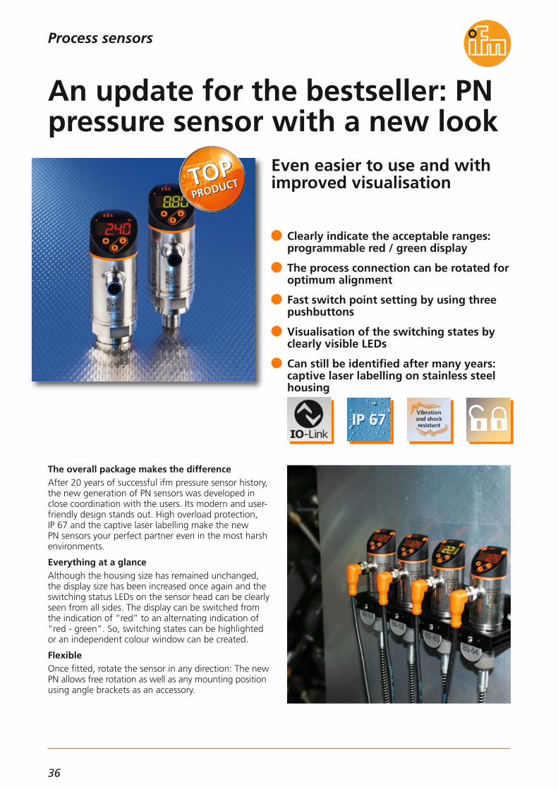
Even easier to use and withimproved visualisation
The overall package makes the differenceAfter 20 years of successful ifm pressure sensor history,the new generation of PN sensors was developed inclose coordination with the users. Its modern and user-friendly design stands out. High overload protection, IP 67 and the captive laser labelling make the new PN sensors your perfect partner even in the most harshenvironments.
Everything at a glanceAlthough the housing size has remained unchanged,the display size has been increased once again and theswitching status LEDs on the sensor head can be clearlyseen from all sides. The display can be switched fromthe indication of “red” to an alternating indication of“red - green”. So, switching states can be highlightedor an independent colour window can be created.
FlexibleOnce fitted, rotate the sensor in any direction: The newPN allows free rotation as well as any mounting position using angle brackets as an accessory.
Clearly indicate the acceptable ranges: programmable red / green display
The process connection can be rotated foroptimum alignment
Fast switch point setting by using threepushbuttons
Visualisation of the switching states byclearly visible LEDs
Can still be identified after many years:captive laser labelling on stainless steelhousing
An update for the bestseller: PNpressure sensor with a new look

37
(11.2014)
TOP
PRO
DU
CTS
Process sensors
For further technical details please visit: www.ifm.com
Pressure sensors
Accessories
Type Description Order no.
Memory plug, parameter memory for IO-Link sensors E30398
IO-Link interface, current consumptionfrom USB port E30396
Operating voltage [V DC] 18...30
Current rating [mA] 200(up to 60 ° environment)
Accuracy / deviation(in % of the span) turn down 1:1Deviation of the switch pointLinearity error
Repeatability
Temperature coefficients (TEMPCO)in the temperature range 0 ... 80 °C(in % of the span per 10 K)Greatest TEMPCO of zeroGreatest TEMPCO of the span
< ± 0.5< ± 0.25 (BFSL)
< ± 0.5 (LS)< ± 0.1
< ± 0.2< ± 0.2
Communication interfaceIO-Link 1.1
COM2 slave; 38.4 kbaud
Medium temperature [°C] -25...80
Switching frequency [Hz] ≤ 170
Protection IP 67
Shock resistance [g] 50
Vibration resistance [g] 20
Type of pressure: relative pressureLiquids and gases
Common technical data
Connection technology
Type Description Order no.
Socket, M12,2 m black, PUR cable EVC001
Socket, M12,5 m black, PUR cable EVC002
Socket, M12,2 m black, PUR cable EVC004
Socket, M12,5 m black, PUR cable EVC005
Tag clip E30422
Damping screw, G 1/4 female E30419
Damping screw, G 1/4 male E30057
Protective cover, new generation E30420
Angle bracket, PA66 E30421
Siphon, G 1/4,steel (1.0345) E30140
M12 connector · output function programmable 2 x NO/NC 2 x NO/NC+ analogue: 4...20 mA/0...10 V
0...400 PN7570
0...250 PN7571
0...100
800
500
300
1700
1200
650 PN7592
Measuring rangerelative pressure
[bar]
Order no.G 1/4 male
Poverloadmax.[bar]
Pburstmin.[bar]
0...25 PN7593
-1...10 PN7594
0...2,5
150
75
20
350
150
50 PN7596
PN7070
PN7071
PN7092
PN7093
PN7094
PN7096
0...1 PN7597
-1...1
10
20
30
50 PN7599
PN7097
PN7099
-1...0 20 50 ––
Order no.G 1/4
female
Order no.G 1/4 male
0...600 PN7560800 2500 PN7160
Order no.G 1/4
female
LINERECORDER SENSOR, software for parameter setting and set-up of IO-Link sensors
ZGS210
USB IO-Link master for parameter settingand analysis of units E30390
PN3570*
PN3571*
PN3592*
PN3593*
PN3594*
PN3596*
PN3070*
PN3560*PN3160*
PN3071*
PN3092*
PN3093*
PN3094*
PN3096*
PN3597*
–
PN3097*
–
PN3529*PN3129*
*IO-Link in preparation, available as from 02/2015

38
Reliable and fast alternativeto tuning forks
The LMT point level sensor protects the pump fromrunning dry.
Level under controlThe LMT family reliably monitors the level in storagetanks or protects pumps against running dry. The diffe-rent lengths and process connections allow application-specific and orientation-independent installation.
Versatile sensor for all mediaThe LMT can be set to almost any liquid or viscous media and bulk materials.The distinction of two media is possible due to the twoswitching outputs which can be set independently. Theparameters can be set via IO-Link and USB interface accessory E30396.
Food-gradeThe sensor with its high-quality housing materials suchas high-grade stainless steel (316L / 1.4404) and PEEKmeets all requirements for hygienic areas. This includesapprovals such as EHEDG, 3A and also FDA.
Flexible installation independent of theorientation
Shock and vibration resistant in a robuststainless steel housing
Factory set for simple “plug & play”
Differentiation of media by switch pointsetting
Hygienic design with maintenance-freesealing concept
Hygienic point level sensor perfectly suppresses deposits
Process sensors

39
(04.2014)
TOP
PRO
DU
CTS
Level sensors
Process connection
Installationlength [mm]
Approval Medium temperatureoils, fats, bulk materials
[°C]
Order no.
Medium: Aqueous mediaM12 connection · output function 2 x NO/NC programmable · 4-wire DC PNP · IO-Link 1.1
Medium temperaturewater-based media
[°C]
G 1/2 12 EHEDG, FDA, 3A 0...85 0...100 LMT100
G 1/2 153 EHEDG, FDA -20...85 -20...100 LMT104
G 1/2 253 EHEDG, FDA -20...85 -20...100 LMT105
Accessories
Type Descriptionhigh-grade stainless steel
Order no.
Medium temperature [°C] 150 (max. 1 h)
Housing materials
PEEK,high-grade stainless steel
(316L/1.4404), PA12, FPM
Protection IP 68 / IP 69K, III
Materials wetted partsPEEK,
high-grade stainless steel(316L/1.4404), FPM
Shock resistance [g] 50
Vibration resistance [g] 20
Ambient temperature [°C] -40...85
EMCClosed tanks:Open tanks:
EN 6100-6-2:2005EN 6100-6-3:2006EN 6100-6-4:2006
Operating voltage [V] 18...30 DC
Current rating [mA] 100
Further technical data
Clamp adapter G 1/2 female – Clamp 1"– 1.5" E33401
Clamp adapter G 1/2 female – Clamp 2" E33402
Welding adapter ball, G 1/2 E30055
Welding adapter collar, G 1/2 E30056
Welding adapter, cylindrical, for tanks, G 1/2 E43300
Welding adapter, cylindrical, for pipes, G 1/2 E4330
Screw-in adapter G 1/2 female – G 3/4 male E43302
Screw-in adapter G 1/2 female – G 1 male E43303
Screw-in adapter G 1/2 female – 3/4 NPT E43313
Clamp adapter, G 1/2 female – Varivent D50 E43306
Clamp adapter, G 1/2 female – Varivent D68 E43307
Clamp adapter with leakage port, G 1/2 female – Clamp 1"– 1.5" (3-A) E43311
Clamp adapter with leakage port, G 1/2 female – Clamp 1"– 2" (3-A) E43312
Accessories
Type Description Order no.
IO-Link interface for parameter settingand analysis of units with DTM specification, current consumption viaUSB port: max. 500 mA
E30396
Memory plug, parameter memory for IO-Link sensors E30398
For further technical details please visit: www.ifm.com
Process sensors
Medium: Oils, fats, powdersM12 connection · output function 2 x NO/NC programmable · 4-wire DC PNP · IO-Link 1.1
G 1/2 12 EHEDG, FDA, 3A 0...85 0...100 LMT110
Medium: Sugary media with low water contentM12 connection · output function 2 x NO/NC programmable · 4-wire DC PNP · IO-Link 1.1
G 1/2 12 EHEDG, FDA, 3A -40...85 -40...100 LMT121
Welding adapter G 1/2, long design for deeper installation E43319
LINERECORDER SENSOR, software for parameter setting and set-up of IO-Link sensors
ZGS210
G 1 38 EHEDG, FDA -20...85 -20...100 LMT302
G 3/4 28 EHEDG, FDA -20...85 -20...100 LMT202
G 1/2 38 EHEDG, FDA, 3A -20...85 -20...100 LMT102

40
Process sensors
Compact temperature transmitter with excellent response time and IO-Link 1.1
VersatileThe TA type temperature sensor is a universal transmitter with a 4...20 mA current output which can be scaledover the -50 to 150 °C measuring range. Scaling is done simply via the integrated IO-Link interface
FlexibleThe compact design, the integrated process connections and a multitude of probe lengths enable particularlysimple installation.
TransparentAn integrated LED clearly signals the readiness for operation.
Fast and preciseA high level of accuracy is achieved using a class A accuracy Pt1000 sensor and factory calibration. In addition, ifm’s tried and tested film technology ensures excellent dynamic response times. So this sensor is suited for all highly precise and rapid processes.
Space-saving in all installation positions
LED for visualisation of the operating status
Fast response time: T05 / T09 = 1 s / 3 s
Pressure resistant up to 400 bar
Different installation lengths from25...150 mm
Small but effective: temperaturetransmitter in compact housing

41
(04.2014)
TOP
PRO
DU
CTS
Process sensors
For further technical details please visit: www.ifm.com
Temperature sensors
Nominal length
[mm]
Order no.
Pressure resistance
[bar]
Process connection G ½Temperature range (scaled 4…20 mA) -50…150 °C
TA240530 300
TA241550 300
TA2435100 160
TA2445150 160
Process connection G ¼Temperature range (scaled 4…20 mA) -50…150 °C
TA210525 400
TA211550 400
TA2135100 160
TA2145150 160
Operating voltage [V DC] 18...32
Protection IP 67, IP 68, IP 69K / lll
Materials (wetted parts) high-grade stainless steel(316L/1.4404)
Further technical data
Reverse polarity / overload protection • / •
Measuring element Pt1000, class A
Response dynamics T05 / T09 1 s / 3 s
Accuracy [K] ± 0.3 + (± 0.1 % MS)
Measuring range [°C] -50...150
Ambient temperature [°C] -25...80
IO-Link revision 1.1IO-Link interface for parameter settingand analysis of units with DTM specification, current consumption via USB port: max. 500 mA
E30396
Memory plug, parameter memory for IO-Link sensors E30398
LINERECORDER SENSOR, software for parameter setting and set-up of IO-Link sensors
ZGS210
Accessories
Type Description Order no.
Dimensions
Wiring diagram
Connection technology
Type Description Order no.
Socket, M12,2 m black, PUR cable EVC001
Socket, M12,5 m black, PUR cable EVC002
Socket, M12,2 m black, PUR cable EVC004
Socket, M12,5 m black, PUR cable EVC005
6
M12
x118
,7
15,9 48 14
26LED G ½
EL
L+
L3
1
4
2IO-Link
L+
L
1
2
TA24
6
M12
x118
,7
15,9 48
19
13
G ¼LED
ELTA21
42
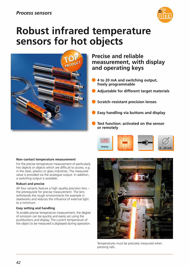
Precise and reliable measurement, with displayand operating keys
Temperatures must be precisely measured when pressing rails.
Non-contact temperature measurementFor the precise temperature measurement of particularly hot objects or objects which are difficult to access, e.g.in the steel, plastics or glass industries. The measuredvalue is provided via the analogue output. In addition, a switching output is available.
Robust and preciseAll four variants feature a high-quality precision lens –the prerequisite for precise measurement. The lenswithstands the rough environments for example insteelworks and reduces the influence of external lightto a minimum.
Easy setting and handlingTo enable precise temperature measurement, the degree of emission can be quickly and easily set using thepushbuttons and display. The current temperature ofthe object to be measured is displayed during operation.
4 to 20 mA and switching output, freely programmable
Adjustable for different target materials
Scratch-resistant precision lenses
Easy handling via buttons and display
Test function: activated on the sensor or remotely
Robust infrared temperature sensors for hot objects
Process sensors
43
(04.2014)
TOP
PRO
DU
CTS
Temperature sensors
Accessories
Type Description Order no. Operating voltage [V DC] 18...32
Short-circuit protection •
Common technical data
Connection technology
Type Description Order no.
M12 socket, shielded,2 m black, PUR cable EVC547
M12 socket, shielded,5 m black, PUR cable EVC548
M12 socket, shielded,2 m black, PUR cable EVC544
M12 socket, shielded,5 m black, PUR cable EVC545
Current consumption [mA] ≤ 50
Ambient temperature [°C] 0...65
Protection IP 65
Reverse polarity protection •
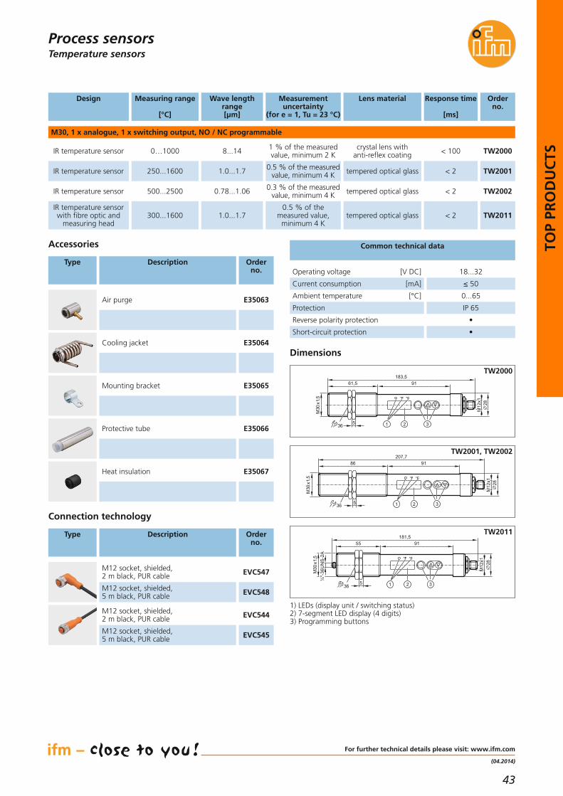
Design Order no.
Measuring range
[°C]
Wave lengthrange[μm]
Lens material Response time
[ms]
M30, 1 x analogue, 1 x switching output, NO / NC programmable
TW2000IR temperature sensor 0…1000 8...14 crystal lens with anti-reflex coating < 100
IR temperature sensor 250...1600 1.0...1.7
Measurement uncertainty
(for e = 1, Tu = 23 °C)
1 % of the measuredvalue, minimum 2 K
0.5 % of the measuredvalue, minimum 4 K tempered optical glass < 2
Air purge E35063
Cooling jacket E35064
Mounting bracket E35065
Protective tube E35066
Heat insulation E35067
Dimensions
TW2001
IR temperature sensor 500...2500 0.78...1.06 0.3 % of the measuredvalue, minimum 4 K tempered optical glass < 2 TW2002
IR temperature sensorwith fibre optic and
measuring head300...1600 1.0...1.7
0.5 % of the measured value,
minimum 4 Ktempered optical glass < 2 TW2011
For further technical details please visit: www.ifm.com
Process sensors
28
61,5 91
M30
x1,5
183,5
M12
x1
536 21 3
°F °C
28
86 91
M30
x1,5
207,7
M12
x1
536 21 3
°F °C
28
55 91
M30
x1,5
¼"-
36U
NS
-2A
181,5
M12
x1
536 21 3
°F °C
TW2000
TW2001, TW2002
TW2011
1) LEDs (display unit / switching status)2) 7-segment LED display (4 digits)3) Programming buttons

44
Process sensors
First transmitter with display and IO-Link for food applications
TD temperature transmittersThe TD series temperature transmitters are distinguishedby a compact, hygienic design with integrated processconnections and a display for local indication of thetemperature.
Easy installation and set-upThe integrated Tri-Clamp® and G1/2"process connections allow quick and easy installation. No complex set-up isrequired because the transmitters are supplied with apre-scaled measuring range. For special applicationsthe temperature range can be scaled via IO-Link 1.1.
Robust and durableProtected to IP 69K standards and featuring a fully welded stainless steel housing, the transmitters are designed to operate in particularly harsh applications.
Bright 4-digit LED display for optimum readability
Fast response time T05/09 = 1/3 s
Pre-scaled measuring ranges, IO-Link 1.1programmable
Available in various probe lengths from30...250 mm
Hygienic and robust design: high-gradestainless steel (316L / 1.4404) and IP 69K
Temperature transmitter withdisplay and IO-Link

45
(04.2014)
TOP
PRO
DU
CTS
For further technical data please go to: www.ifm.com
Process sensorsTemperature sensors
Connection technology
Type Description Order no.
Process connection 1.5" Tri-clamp • 3A, FDA
Process connection 2" Tri-clamp • 3A, FDA
Process connection G 1/2 BSPP hygienic • EHEDG, FDA
Socket, M12, 4-pole,5 m orange, PVC cable EVT001
Socket, M12, 4-pole,2 m orange, PVC cable EVT064
Socket, M12, 4-pole,5 m orange, PVC cable EVT004
Socket, M12, 4-pole,2 m orange, PVC cable EVT067
Accessories
Type Description Order no.
Operating voltage [V DC] 18...32
Ambient temperature [°C] -25...80
Housing materialhigh-grade stainless steel
(1.4404 / 316L) fully welded
Further technical data
Accuracy analogue output [K] ± 0.3 + (± 0.1 % MS)
Programmable IO-Link
Maximum measuring range [°C] -50...150
Protection IP 69K
Welding adapter ball, G 1/2 E30055
Welding adapter collar, G 1/2 E30056
Pipe fitting, G1/2 – DN25 SMS, high-grade stainless steel (1.4404 / 316L) E33430
Sealing plug, G1/2, high-grade stainless steel (1.4435 / 316L) E43308
Dynamic response [s] 1/3 (to DIN EN 60751)
Pipe fitting,G 1/2 I – DIN 11851 DN25 E43304
Pipe fitting,G 1/2 I – DIN 11851 DN40 E43305
Clamp adapter, G 1/2 I – Varivent D50 E43306
Clamp adapter, G 1/2 I – Varivent D68 E43307
IO-Link interface for parameter settingand analysis of units with DTM specification, current consumption via USB port: max. 500 mA
E30396
Memory plug, parameter memory for IO-Link sensors E30398
LINERECORDER SENSOR, software for parameter setting and set-up of IO-Link sensors
ZGS210
Accessories
Type Description Order no.
Welding adapter, G 1/2, high-grade stainless steel (1.4435 / 316L) E43319
Welding adapter, 6 mm, high-grade stainless steel (1.4435 / 316L) E30407
Process connection Ø 6 mm • EHEDG, FDA
Nominal length
-10...150 °C0...100 °C
TD280730
TD281750
TD2837100
TD2847
TD2801
TD2811
TD2831
TD2841150
TD290730
TD291750
TD2937100
TD2947
TD2901
TD2911
TD2931
TD2941150
TD250730
TD251750
TD2537100
TD2547
TD2501
TD2511
TD2531
TD2541150
TD221750
TD2237100
TD2247150
TD2267
TD2211
TD2231
TD2241
TD2261250
Order no.Factory setting
[mm]

46
12.1" TFT display with 1024 x 768 pixels and optionaltouch screen
PDM360 NG-12 dialogue moduleIn almost all mobile machines, there is an increasing demand for large powerful process and dialogue modules for operation and visualisation. With its high-resolutiongraphic display, the powerful 32-bit controller and theflexible programming according to IEC 61131-3, thePDM360 NG-12 is such a user interface.State-of-the-art display technology with optical bonding and the optional resistive touch function enable readability even under adverse conditions. Thanks tothe robust housing with IP 65 / IP 67 protection, the de-vice can be used inside or outside the cabin, for surfaceor panel mounting.The CAN interfaces, Ethernet, USB and the video inputsserve for networking and communication with othervehicle components.
TFT display with ”optical bonding“ enables optimum readability
Backlit function keys and navigation keyswith tactile feedback
Internal mass storage, USB interface, in-terfaces for analogue cameras
4 CAN interfaces with CANopen and SAE J1939 protocol
Programmable to IEC 61131-3 with CODESYS
XL dialogue module PDM360 NG-12 for mobile machines
Systems for mobile machines
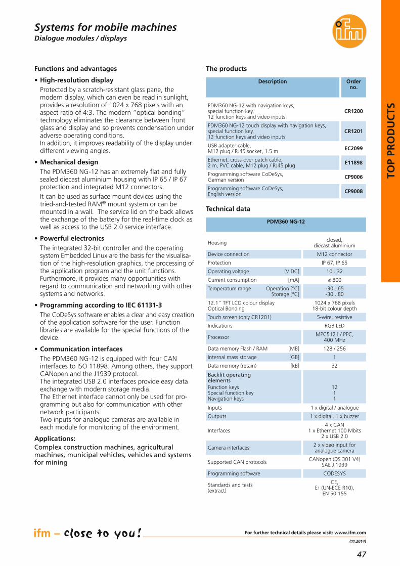
47
(11.2014)
TOP
PRO
DU
CTS
Dialogue modules / displays
Description Orderno.
PDM360 NG-12 with navigation keys, special function key, 12 function keys and video inputs
CR1200
PDM360 NG-12 touch display with navigation keys, special function key, 12 function keys and video inputs
CR1201
USB adapter cable, M12 plug / RJ45 socket, 1.5 m EC2099
Ethernet, cross-over patch cable, 2 m, PVC cable, M12 plug / RJ45 plug E11898
Programming software CoDeSys, German version CP9006
Programming software CoDeSys, English version CP9008
Technical data
PDM360 NG-12
The products
Housing closed, diecast aluminium
Device connection M12 connector
Protection IP 67, IP 65
Operating voltage [V DC] 10...32
Functions and advantages
• High-resolution displayProtected by a scratch-resistant glass pane, the modern display, which can even be read in sunlight,provides a resolution of 1024 x 768 pixels with anaspect ratio of 4:3. The modern ”optical bonding“technology eliminates the clearance between frontglass and display and so prevents condensation underadverse operating conditions. In addition, it improves readability of the display under different viewing angles.
• Mechanical designThe PDM360 NG-12 has an extremely flat and fullysealed diecast aluminium housing with IP 65 / IP 67protection and integrated M12 connectors.It can be used as surface mount devices using thetried-and-tested RAM® mount system or can bemounted in a wall. The service lid on the back allowsthe exchange of the battery for the real-time clock aswell as access to the USB 2.0 service interface.
• Powerful electronicsThe integrated 32-bit controller and the operating system Embedded Linux are the basis for the visualisa-tion of the high-resolution graphics, the processing ofthe application program and the unit functions. Furthermore, it provides many opportunities with regard to communication and networking with othersystems and networks.
• Programming according to IEC 61131-3The CoDeSys software enables a clear and easy creation of the application software for the user. Function libraries are available for the special functions of thedevice.
• Communication interfacesThe PDM360 NG-12 is equipped with four CAN interfaces to ISO 11898. Among others, they supportCANopen and the J1939 protocol.The integrated USB 2.0 interfaces provide easy dataexchange with modern storage media. The Ethernet interface cannot only be used for pro-gramming but also for communication with othernetwork participants.Two inputs for analogue cameras are available ineach module for monitoring of the environment.
Applications:Complex construction machines, agricultural machines, municipal vehicles, vehicles and systemsfor mining
Current consumption [mA] ≤ 800
Temperature range Operation [°C]Storage [°C]
-30...65-30...80
12.1“ TFT LCD colour display Optical Bonding
1024 x 768 pixels18-bit colour depth
Processor MPC5121 / PPC, 400 MHz
Indications RGB LED
Data memory Flash / RAM [MB] 128 / 256
Internal mass storage [GB] 1
Data memory (retain) [kB] 32
Backlit operatingelementsFunction keysSpecial function key Navigation keys
1211
Interfaces4 x CAN
1 x Ethernet 100 Mbits2 x USB 2.0
Outputs 1 x digital, 1 x buzzer
Inputs 1 x digital / analogue
Supported CAN protocols CANopen (DS 301 V4)SAE J 1939
Camera interfaces 2 x video input for analogue camera
Programming software CODESYS
Standards and tests(extract)
CE, E1 (UN-ECE R10),
EN 50 155
For further technical details please visit: www.ifm.com
Systems for mobile machines
Touch screen (only CR1201) 5-wire, resistive

48
Suitable for industrial, mobile, cooling and lubricating applications
Inductive sensors
Capacitive sensors
Capacitive touch sensors in compact cylindrical design (04.2014)
Valve feedback in ATEX zones
Feedback systems for valves and valve actuators
(04.2014)
(04.2014)
Position sensors
Sensors for motion control
Photoelectric sensors for general applications
Photoelectric sensor O7 – now even more powerful (11.2014)
Speed sensors for drives and axes
Speed sensors
(04.2014)
Easy and reliable rotational speed monitoring and standstill detectionSafe monitoring of speeds
Pulse evaluation systems
(11.2014)
(04.2014)
Flow sensors / flow meters
Compressed air meter independent of pipe sizeRobust mechatronic flow sensor
(04.2014)
(04.2014)
Process sensors
Temperature measurement – flush and hygienicExtra protection for temperature sensors
Temperature sensors
(11.2014)
(11.2014)
Small and powerful – AS-i SmartLine module for control cabinetsAS-i ClassicLine – Fast detection and processing of 4...20 mASmall but effective – robust and flexible AS-i miniature module
AS-Interface I /O modules
(11.2014)
(11.2014)
(04.2014)
Industrial communication
Industry 4.0 made easy – apps instead of expensive programming
System solutions
(11.2014)
50 - 53
54 - 55
56 - 57
58 - 59
60 - 61
62 - 6364 - 65
66 - 6768 - 69
70 - 7172 - 73
74 - 7576 - 7778 - 79
80 - 81

49
INN
OV
ATI
ON
S
Accelerometer with compact design and M12 connectionVibration monitoring in ATEX applicationsFrom process monitoring to vibration analysisFor process monitoring with high peak accelerations
Vibration monitoring systems
(11.2014)
(04.2014)
(04.2014)
(04.2014)
Condition monitoring systems
More power in mobile machinesMany inputs and outputs for little money
Mobile controllers
(11.2014)
(04.2014)
Looking for a bigger size? ecomatmobile BasicDisplay XL
Dialogue modules / displays
(04.2014)
Systems for mobile machines
Simple, low price and flexible: RFID for machine control
RFID 125 kHz / RFID 13.56 MHz
(04.2014)
Identification systems
The UHF system with integrated EtherNet/ IP
RFID UHF
(11.2014)
The new compact multicode reader – Fast – Robust
1D/2D code readers
(11.2014)
88 - 8990 - 9192 - 9394 - 95
96 - 9798 - 99
100 - 101
82 - 83
84 - 85
86 - 87
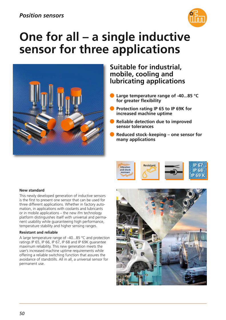
50
Suitable for industrial, mobile, cooling and lubricating applications
New standardThis newly developed generation of inductive sensors is the first to present one sensor that can be used forthree different applications. Whether in factory auto-mation, in applications with coolants and lubricants or in mobile applications – the new ifm technologyplatform distinguishes itself with universal and perma-nent usability while guaranteeing high performance,temperature stability and higher sensing ranges.
Resistant and reliableA large temperature range of -40...85 °C and protectionratings IP 65, IP 66, IP 67, IP 68 and IP 69K guaranteemaximum reliability. This new generation meets theuser’s increased machine uptime requirements while offering a reliable switching function that assures theavoidance of standstills. All in all, a universal sensor forpermanent use.
Large temperature range of -40...85 °C for greater flexibility
Protection rating IP 65 to IP 69K for increased machine uptime
Reliable detection due to improved sensor tolerances
Reduced stock-keeping – one sensor formany applications
One for all – a single inductivesensor for three applications
Position sensors

51
INN
OV
ATI
ON
S
Inductive sensorsPosition sensors
Sensing range
[mm]
Switching frequency
[Hz]
Electrical design Order no.Output functionnormally closed
Type M12 · Dimensions: length [mm]
4 f 700DC PNP IFS248
M12 connector
7 nf 700DC PNP IFS250
4 f 700DC NPN IFS249
7 nf 700DC NPN IFS251
8 f 400DC PNP IGS240
M12 connector
12 nf 300DC PNP IGS242
8 f 400DC NPN IGS241
12 nf 300DC NPN IGS243
15 f 100DC PNP IIS234
M12 connector
22 nf 100DC PNP IIS236
15 f 100DC NPN IIS235
22 nf 100DC NPN IIS237
IFS260
IFS261
IFS262
IFS263
IGS252
IGS253
IGS254
IGS255
IIS246
IIS247
IIS248
IIS249
Order no.Output functionnormally open
IFS240
IFS241
IFS242
IFS243
IGS232
IGS233
IGS234
IGS235
IIS226
IIS227
IIS228
IIS229
IFS244
IFS245
IFS246
IFS247
IGS236
IGS237
IGS238
IGS239
IIS230
IIS231
IIS232
IIS233
Connection
60 45 60 45
Type M18 · Dimensions: length [mm] 60 45 60 45
Type M30 · Dimensions: length [mm] 60 50 60 50
Installation: f = flush / nf = non flush
Dimensions
IFS240 IFS244 IFS241
IFS245 IGS232 IGS236
IGS233 IGS237 IIS226
IIS230 IIS227 IIS231
4945
M12
x1
M12
x1
60
LED 4 x 90° 174
3430
M12
x1
4
M12
x1
45
LED 4 x 90°17
4940
M12
x1
174
M12
x1
60
LED 4 x 90°
5
3425
M12
x1
174
M12
x1
45
LED 4 x 90°
5
M18
x1
M12
x1
4549
60
LED 4 x 90° 244
M18
x1
M12
x1
30
4534
4LED 4 x 90° 24
M18
x1
35 10
M12
x1
60
LED 4 x 90°
49
244
M18
x1
M12
x1
20
4534
4
10
24LED 4 x 90°
45
M30
x1,5
4960
M12
x1
LED 4 x 90° 5 36
M30
x1,5
3935
50
M12
x1
LED 4 x 90° 536
4930
M30
x1,5
5
60
M12
x1
LED 4 x 90°
15
36
15
M30
x1,5
3920
50
M12
x1
LED 4 x 90° 5 36

52
Position sensors
Sensing range
[mm]
Switching frequency
[Hz]
Electrical design
Type M12 · Dimensions: length [mm]
4 b 700DC PNP
PUR cable 2m
7 nb 700DC PNP
4 b 700DC NPN
7 nb 700DC NPN
8 b 400DC PNP
PUR cable 2m
12 nb 300DC PNP
8 b 400DC NPN
12 nb 300DC NPN
15 b 100DC PNP
PUR cable 2m
22 nb 100DC PNP
15 b 100DC NPN
22 nb 100DC NPN
Order no.Output functionnormally open
IFS252
IFS253
IFS254
IFS255
IGS244
IGS245
IGS246
IGS247
IIS238
IIS239
IIS240
IIS241
IFS256
IFS257
IFS258
IFS259
IGS248
IGS249
IGS250
IGS251
IIS242
IIS243
IIS244
IIS245
Connection
60 40
Type M18 · Dimensions: length [mm] 60 40
Type M30 · Dimensions: length [mm] 60 45
Installation: f = flush / nf = non flush
Dimensions
M12
x1
5460
1
4
17
IFS252
1
M12
x1
34
4
17
40
IFS256
M12
x1
4960
51
4
17
IFS253
M12
x1
2940
51
4
17
IFS257
1
M18
x1
52,560
4
24
IGS244
1M
18x1
32,540
4
24
IGS248
1
M18
x1
42,560
4
24
10
IGS245
1
M18
x1
22,540
4
24
10
IGS249
M30
x1,5
52,560
365
1
IIS238
M30
x1,5
37,545
365
1
IIS242
M30
x1,5
37,560
365
1
15
IIS239
M30
x1,5
22,545
365
1
15
IIS243
1) LED (yellow)

53
INN
OV
ATI
ON
S
(04.2014)
For further technical data please go to: www.ifm.com
Type Description Order no.
Accessories
Angle bracket for type M30,stainless steel E10737
Mounting clamp, with end stop for types M12, PC E11994
Mounting clamp, with end stop for types M18, PC E11995
Mounting clamp, with end stop for types M30, PC E11996
Angle bracket for type M12,stainless steel E10735
Angle bracket for type M18,stainless steel E10736
Operating voltage [V DC]10...30 DC;
"supply class 2"to cULus
Current consumption [mA] < 10
Reverse polarity protection •
Voltage drop [V] < 2.5
Current rating [mA] 100
Ambient temperature [°C] -40...85
Switching status indication LED yellow
Protection IP 65 / IP 66 / IP 67 / IP 68 / IP 69K
Housing materialsBrass
white bronze coated, PBT; PEI
Accessories (supplied) 2 lock nuts, brass
Further technical data
Connection technology
Type Description Order no.
Socket, M12,2 m black, PUR cable EVC001
Socket, M12,5 m black, PUR cable EVC002
Socket, M12,2 m black, PUR cable EVC004
Socket, M12,5 m black, PUR cable EVC005
Inductive sensorsPosition sensors
L+
L
1
4
3
Wiring diagramM12 connector
L+
L
1
2
3
L+
L
1
4
3
L+
L
1
2
3
BN
BK
BU
L+
L
Wiring diagramPUR cable 2m
L
BN
BK
BU
L+
Short-circuit protection •
Overload protection •
EMCEN 61000-4-2 ESD:EN 61000-4-3 HF radiated:EN 61000-4-4 Burst:EN 61000-4-6 HF conducted:EN 55011:
4 kV CD / 8 kV AD10 V/m (80...1000 MHz)
2 kV10 V (0.15...80 MHz)
class B
Mounting sleeve, M16 x 1 - Ø 12 mm, 34 mm E10806
Mounting sleeve, M24 x 1.5 - Ø 18 mm, 36 mm E10807
Mounting sleeve, M36 x 1.5 - Ø 30 mm, 36 mm E10808
Mounting accessories
Plastic housing, 24 V DC, 2.5 A DN1031
Metal housing, 24 V DC, 3.3 A DN4011
Power supplies

54
Capacitive touch sensors incompact cylindrical design
Functions and technologyCapacitive touch sensors can be used, for example, asstart and stop function on machines, as enable switchand for opening and closing gates. Compared to mechanical switches the sensors operate without wear.Dynamic touch sensors detect an approaching humanhand and suppress interference such as water, layers of ice or foreign bodies to a large extent. However, agloved hand will still trigger them.Static touch sensors detect hands and objects eventhrough glass for as long as the sensing face is coveredwhich provides, for example, protection against vanda-lism. With the latching operating principle it is possibleto switch the sensor on by touching briefly and to switch it off again by touching briefly again. Furthermore, thehousing is resistant to oils and it is also impact andscratch resistant. It offers the protection rating IP 69K.LEDs for optical feedback signal that the sensor hasbeen activated. The green LEDs can be controlled sepa-rately and, for example, be used to indicate the statusof plant and machinery.
Dynamic, static function, preset
High IP 69K protection rating and widetemperature range -40...85 °C
Symbols on the sensing face can be selected separately
Easy installation into housing with Ø 22.5 mm bore thanks to M22 x 1.5 thread
Wear-free and maintenance-free thanks to switching without any mechanical pressure
Touch sensor – start, stop and acknowledge
Position sensors

55
INN
OV
ATI
ON
S
(04.2014)
Operating voltage [V DC] 24 (12...30)
Current consumption [mA] 45
Ambient temperature [°C] -40...85
Common technical data
Capacitive sensors
Dimensions
295,3
5
31
M22x1,5
Mounting optionsThe sensor can be installed in all housings with a Ø22.5 mm hole. The supplied lock nut is used for fixing.Thanks to the M22 thread the sensor can be used for screw mounting without lock nut. Installationalignment of the sensor is not necessary since the clipshowing the symbol for the sensing face is snappedin as the last step.Wiring is done via the tried-and-tested 3- or 4-wire technology.
Position sensors
Connection Current rating
[mA]
Protection Orderno.
Output function NO · DC PNP
dynamic 0.3 m PUR cable 500IP65, IP67, IP69K KT5101M22
Housing material
PA
dynamic 0.3 m PUR cable with M12 plug 500IP65, IP67, IP69K KT5102M22 PA
static 0.3 m PUR cable 500IP65, IP67, IP69K KT5105M22 PA
static 0.3 m PUR cable with M12 plug 500IP65, IP67, IP69K KT5106M22 PA
dynamic 0.3 m PUR cable 500IP65, IP67, IP69K KT5109M22 PA
Type Evaluation principle
Accessories
Socket, M12,2 m black, PUR cable EVC001
Socket, M12,5 m black, PUR cable EVC002
Socket, M12,2 m black, PUR cable EVC004
Socket, M12,5 m black, PUR cable EVC005
Symbol disc must be ordered separately
For further technical data please go to: www.ifm.com
Connection technology
Type Description Orderno.
static 0.3 m PUR cable 500IP65, IP67, IP69K KT5305M22 Stainless steel
dynamic 0.3 m PUR cable 500IP65, IP67, IP69K KT5301M22 Stainless steel
Output function NO · DC PNP · green LED can be controlled separately
Symbol disc, lettering: START E12377
Symbol disc, lettering: STOP E12378
Symbol disc,symbol: on E12379
Symbol disc,symbol: off E12380
Symbol disc,transparent E12386
Type Description Order no.
Plastic housing, 24 V DC, 2.5 A DN1031
Power supplies
Type Description Order no.

56
Precise, compact, interferenceimmune: new version of thetried-and-tested O7 design!
Precise, compact, interference immuneIn applications where space is limited and high precision is required, the new generation of compact O7 photo-electric sensors comes into play. The very precise background suppression is particularlyreliable, even in case of highly reflective objects. The visible light spot, without scattered light, enables easyalignment of the sensor to the object. Therefore, typicalapplications are feeding and handling, where particularly small parts need to be detected.
Plug & PlayThe O7 sensors have a fixed setting. For quick and easymounting, O7 is equipped with integrated M3 metalthreaded sleeves. Plug & play for simple setup, saving time and money.
Reliable background suppression
Precise object detection without scatteredlight thanks to the well-defined light spot
Long ranges and compact design
Ideal for applications in feeding and handling
Photoelectric sensor O7 – noweven more powerful
Position sensors

57
INN
OV
ATI
ON
S
(11.2014)
Laser sensors / distance measurement sensors
For further technical details please visit: www.ifm.com
Position sensors
Power supplies
Type Description Orderno.
Metal housing, 24 V DC, 3.3 A DN4011
Accessories
Type Description Orderno.
Mounting set for clamp mounting,stainless steel E21237
Mounting set for free-standing mounting, stainless steel E21238
Mounting set for free-standing mountingwith fine adjustment, stainless steel E21239
Mounting set with ball jointgalvanised, stainless steel E21240
Rod, 120 mm, Ø 10 mm,M8 thread, stainless steel E21081
Cube for mounting on an aluminiumprofile, M8 thread, diecast zinc E20950
Prismatic reflector 50 x 50 mm,plastic E20744
M8 connector (3-pole) with 200 mm PUR cable · 3-wire DC
TypeO7
Range
[mm]
Switchingfrequency
[Hz]
Current consumption
[mA]
Order no.
5...30 750 20 O7H200
5...30 O7H201
5...50
750
750
20
20 O7H202
5...50 750 20 O7H203
3...100 750 20 O7H204
3...100
Light spot diameter
[mm]
2.5
2.5
2.5
2.5
7
7
Light-on / dark-on mode
• / –
– / •
• / –
– / •
• / –
– / •750 20 O7H205
Operating voltage [V] 10...30 DC
Type of light red light 633 nm
Short-circuit protection, pulsed •
Current rating [mA] 100
Voltage drop [V] < 2.5
Reverse polarity / overload protection • / •
Ambient temperature [°C] -25...60
Function displaySwitching status LED yellow
Materials housinglens
cable
PAPMMA
PUR
Protection IP 65, III
Common technical data
System
Diffuse reflection sensor withbackground suppression
Diffuse reflection sensor withbackground suppression
Diffuse reflection sensor withbackground suppression
3...1000 1000 20 O7P200
3...1000
55
55
– / •
• / –1000 20 O7P201Retro-reflective sensor with
polarisation filter
0...1500 1000 10 O7E200
0...1500
–
–
– / •
• / –1000 10 O7E201Through-beam – receiver
0...1500 – 20
Order no.
O7H206
O7H207
O7H208
O7H209
O7H210
O7H211
O7P202
O7P203
O7E202
O7E203
O7S20090 –Through-beam – transmitter
9
15
7,6
6,5
LED 9
26 20,3
2,7
M3
Example O7P200
Dimensions
PNPNPN
Connection cable, M8 socket 3-pole / M8 coupling 3-pole, 2 m black, PUR cable
EVC268
Connection cable, M8 socket 4-pole / M8 coupling 3-polig, 5 m black, PUR cable
EVC308

58
Intrinsically safe valveopen/closed sensor for ATEXareas
Direct fit on valve actuatorsTwo sensors built-in; one sensor provides a signal whenthe valve is open, the other when it is closed. Thesetype IND inductive sensors are intrinsically safe and consist of two inductive sensors in a potted and robusthousing with IP 67 protection rating. They are equipped with connection for solenoids.
Fast and easy connectionThe solenoid connection is optionally a standardisedM20 x 1 connector or an M12 connection. The terminalchamber is easy to open and close. Since the terminalblock can be removed, no new wiring is required if thesensor is replaced. The units are approved to ATEX categories 1D/1G and 2G.
Easy access terminal chamber
Removable terminal block for easy wiring
Robust and resistant housing
Permanently legible lasered type label
Actuator interface connection: M20 x 1connector or M12 connector
Valve feedback in ATEX zones
Position sensors

59
INN
OV
ATI
ON
S
(04.2014)
Feedback systems for valves and valve actuators
Switching frequency [Hz] 500
Sensing range [mm] 4
Electrical design
Wiring to certified intrinsi-cally safe circuits with the
max. values: Ui = 15 V / Ii = 50 mA / Pi = 120 mW
Housing material PA
Further technical data
For further technical details please visit: www.ifm.com
Accessories
Type Description Order no.
Switching amplifier, dual channel, transistor N0534A
Switching amplifier, dual channel, relay N0533A
Switching amplifier, dual channel, optocoupler N0532A
Plug for covering the oblong holes,EPDM E12212
Target puck, Ø 53 mm E17320
Target puck, Ø 65 mm E17327
Target puck, Ø 102 mm E17328
Dimensions
33
92
6,3
18,8
60
7,5
5,5
3060M
20x1
,5
Example NN505A
1) Sensor 12) Sensor 23) LED OUT 24) LED OUT 1
Position sensors
Ambienttemperature
[°C]
ProtectionProtection class Orderno.
2 x 2-wire Namur
8.2 DC -25...70 IP65, IP67III NN504AM20 x 1.5 / M20 x 1.5
M20 x 1.5 / M12 8.2 DC -25...70 IP65, IP67III NN505A
Outputfunction
2 x NC
2 x NC
Connectionsensor / valve
Ub
[V]
Screw plugs, PA 6.6 E12209
Cable gland, M20 x 1.5, PA 6.6 E12208
ApprovalMarking of the unit
BVS 14 ATEX E 005 XIECEx BVS 14.0005X
II 1G Ex ia IIB T4 Ga Ta: -25...70 °C
II 2G Ex ia IIC T4 Gb Ta: -25...70 °C
II 1D Ex ia IIIB T135 °C Da Ta: -25...70 °C

60
Magnetic measuring principlefor non-contact detection ofspeed and direction of rotation
Advantages and customer benefitsThe high switching frequency of 15,000 Hz as well asthe extended temperature range of -32...125 °C makeifm's new magnetic MX5 type speed sensors your idealpartner for the detection of speed and direction of rotation on drives, axes and shafts. The sensors use Hall measuring cells, so that theyfunction reliably and without contact even in cases ofheavy soiling.
Quickly integrated everywhereThe sophisticated housing concept offers different com-binations of housing lengths, connections, such asstraight or angled cable outlet and AMP connectors.These are available on request.Toothed wheel modules made of metal are standardised and have a defined tooth width and distance.
Switching frequencies up to 15,000 Hz
Precise detection and reduced phase shift
Wide temperature range: -32…125 °C
Installation within seconds thanks to flanged housing
Flexible combinations of housings, connections and signals
Speed sensors for drives and axes
Sensors for motion control

61
INN
OV
ATI
ON
S
(04.2014)
Speed sensors
For further technical details please visit: www.ifm.com
Accessories
Type Description Order no.
Connection cable, AMP socket, 10 m E60303
Sensors for motion control
Iload
[mA]
Ambient temperaturesensor
[°C]
Order no.
Speed sensors · magnetic measuring principle
0.005...15 < 50 -32...+140 MX501530
Protection ratinghousing
IP 69K
Connection
radial, pigtail AMP Junior Timer
0.005...15 < 50 -32...+140 MX500435 IP 69Kconnector, AMP Junior Timer
0.005...15 < 50 -32...+140 MX501735 IP 69Kaxial, pigtail 0.15 m
0.005...15 < 50 -32...+140 MX500045 IP 69Kconnector, AMP Junior Timer
Installationlength[mm]
f
[kHz]
Operating voltage [V DC] 7...30
Sensing range [mm] 0.4...1.5
Module (toothed wheel) 1.25
Phase shift [°] 90 ± 20
Output 2 x open collector
Further technical dataMoreover, the sensors can be used to select one or two-channel speed detection. Besides speed, the directionof rotation can also be detected using two channels. Also, apart from an NPN or PNP switching output thespeed sensor family covers various module sizes of toothed wheels. The new sensors are adjusted to module 1.25.The flanged housing offers quick mounting and accurate adjustment of the sensor with only one screw. This reduces phase shift and guarantees precise detection ofthe toothed wheel.
Dimensions
61
4,9
14
6,435
32
Example MX5004
Wiring diagram
GND
L+
3
4
2
1A B
GND
L+BNA B
BK
WH
BU

62
Easy and reliable rotationalspeed monitoring andstandstill detection
Use for rotational speed monitoring on conveyor belts,worm gears and elevators.
Low-cost evaluation of rotational speedsThe new rotational speed evaluation systems DD0203and DD0296 supply the basic functions of rotationalspeed monitoring and standstill detection by means ofexternal pulse pick-up (sensor). All settings are intuitivevia four potentiometers: The rotational speed is setusing a logarithmic scale, multiplier (x1 / x100) and out-put function, start-up delay and hysteresis.They feature one semiconductor output and one relayoutput. They open or close (function can be set) in caseof underspeed or overspeed (can also be set).Four LEDs indicate the switching and operating states.The integrated wide-range power supply for voltagesupply from direct or alternating voltage guaranteeshigh flexibility. A 24 V DC output supplies power to theconnected sensors.Thanks to their compatible functions, these new eval-uation systems have replaced the old DA0001/DD0116and DA0001/DA0116 units.
Intuitive handling via potentiometer
Rotational speed detection usingstandard sensors
Small design requiring only verylittle space
Integrated wide-range power supply(24...27 V DC, 110...240 V AC)
Plug-in screw terminals simplifyinstallation
Intuitive monitor for speedand standstill
Sensors for motion control

63
INN
OV
ATI
ON
S
(11.2014)
For further technical details please visit: www.ifm.com
Dimensions
25,4 109,1
93
LED s
3
2
4
35,5
116
1
1) plug-in screw terminals2) panel for labelling3) potentiometer4) DIN rail mounting
Type Ub
[V]
Outputsanalogue
Setting range
[Hz]
Outputstransistor
Outputsrelay
Orderno.
1 pulse input PNP (type 2 to IEC 61131-2)
110...240 AC / 27 (typ. 24) DC50...60 Hz –0.1...10 / 10...1000 11 DD0203
110...240 AC / 27 (typ. 24) DC50...60 Hz –0.2...20 / 20...2000 11 DD0296
Relay outputContact rating [A]
4 (240 V AC, 24 V DC);resistive load
Transistor outputSwitching voltage [V]Current rating [mA]
10...30 DC SELV≤ 100
Auxiliary energy for sensors [V] 18.5...30 DC SELV, ≤ 100 mA
Protection ratinghousing / terminals IP 20 / IP 20
Ambient temperature [°C] -25...60
Display LEDpower supply
input signaloutput
release
1 x green1 x yellow
1 x green (lights when theoutput relay is energised)
1 x yellow
Housing material plastic: PC GF20
Common technical data
Application: Evaluation of pulse sequences with regardto overspeed and underspeed; speed monitoring
Wiring diagram
6
57
21 22 23 24
1817
19
8
1 2 3 4
14
1513
Enable pnp
Sensor supply
In
pnp
or DCACPower
Out
NLL N
Switching diagram
SP + Hy
SP
I
II
III
IV
SP – Hy
1
2
3
[Hz]
[s]
A
B
The upper diagram shows a rotational speed curve includingswitch point (SP, adjustable) and hysteresis (Hy, adjustable) as well asinput frequency (A) as a measure for the rotational speed or speedduring the time (B)1) voltage supply of the speed monitor2) start-up delay (adjustable), suppresses the monitoring when the
machine is started3) switching output according to the set function
I: Monitoring of underspeed, normally open functionII: Monitoring of underspeed, normally closed functionIII:Monitoring of overspeed, normally open functionIV:Monitoring of overspeed, normally closed function
Systems for pulse evaluationSensors for motion control

64
Safe speed monitor uses standard sensors as pick-ups
ApplicationsThe speed monitors DD110S and DD111S have beendeveloped for safety-related maximum-speed monito-ring as used in carousels or centrifuges. The DD111S isspecially designed for the low rotational speed of windturbines.Both speed monitors can also be used for the operatingmode “reduced speed” e.g. on machine tools.
Special featuresThe speed monitor is certified to EN 62061 / SIL 3 andEN ISO 13849-1 cat. 4 / PL e – even though non-safety-related sensors are used as pulse pick-ups.When the safety output has been triggered, it can bereset again manually or automatically.
Easy parameter setting via rotary switch
No restrictions for the design of the cam disc
Monitoring functions can be enabled /disabled
Reliable operation at extreme ambienttemperatures down to -40 °C
Housing width only 25 mm
Safe monitoring of speeds
Sensors for motion control

65
INN
OV
ATI
ON
S
(04.2014)
Safety speed monitor DD110S, DD111S
Evaluation system for safe speed monitoring
Easy setting of the limit speedThe speed is determined via the interval measurementon the inputs where for example two inductive sensorsare used as pulse pick-ups.The user can set the limit speed easily and effectivelyvia three rotary switches (DD110S: x 1, x 10, multiplier /DD111S: x 10, x 1, x 0.1) – either in rpm or Hz. It wasdecided not to use any complicated setting menus.An easy and intuitive setting algorithm prevents unin-tentional change or manipulation of the set values.
More functionsAutomatic or manual reset of overspeed is possible.This function is set via wire links.The monitoring function can be enabled and disabledvia a switching input.Besides the 2-pole safety relay, transistor outputs canalso be used as output for the status and error indication.
For further technical details please visit: www.ifm.com
Dimensions
22,5
99 108
1
LED
2
114,5
3
35,5
Systems for pulse evaluationSensors for motion control
Operating voltage [V DC]19.2...28.8;
incl. 5 % residual ripple
Nominal voltage [V DC] 24
Current consumption [mA] ≤ 125
Sensor supply 24 V DC / ≤ 70 mA
Protection IP 20 / II
Input characteristicsPulse inputs S34, S43:
“1”: 6 mA / 24 V DC
Adjustable [rpm]speed range DD110S 1...49500
Adjustable DD110S [Hz]frequency range DD111S [Hz]
0.5...9900.1...99.9
Max. input frequency [Hz] ≤ 2000
Output function
2 safety-related switchingoutputs (floating contacts)
1 fault output “Fault” (positive switching)1 diagnostic output
“Overspeed” (positiveswitching)
Output characteristics
Fault output “Fault” Y7and diagnostic output
“Overspeed” Y8≤ 20 mA, 24 V DC,
voltage drop ≤ 2 V DC,short-circuit proof,
non safe
Contact rating
6 A, 250 V AC / 24 V DC
(≥ 6 mA); resistive load
Ambient temperature [°C] -40...55
Storage temperature [°C] -40...75
Max. permissible relative [%]humidity
95, non condensing
Housing materials PA (polyamide)
Mounting Rail TH35 (according to EN 60715)
ConnectionScrew terminals; 0.5...2.5 mm² (AWG 12...30)
1) Screw terminals2) Rotary switch3) DIN rail mounting
Wiring diagram
DD11xS
L- L+ S33 S34 S35 S44 S43 S45 13 23
(GND) (GND)
Y3 Y4 Y2 Y1 Y5 Y6 Y7 Y8 14 24
VCC = 24 V DC
24 V DC
Sensor 2 Sensor 1
K1 K2 K1
K2
Enable 1
Enable 2 Fault Overspeed
24 V Restart
Technical data
Accessories
Type Description Order no.
Plastic housing, 24 V DC, 2.5 A DN1031
Metal housing, 24 V DC, 3.3 A DN4011
Power supplies
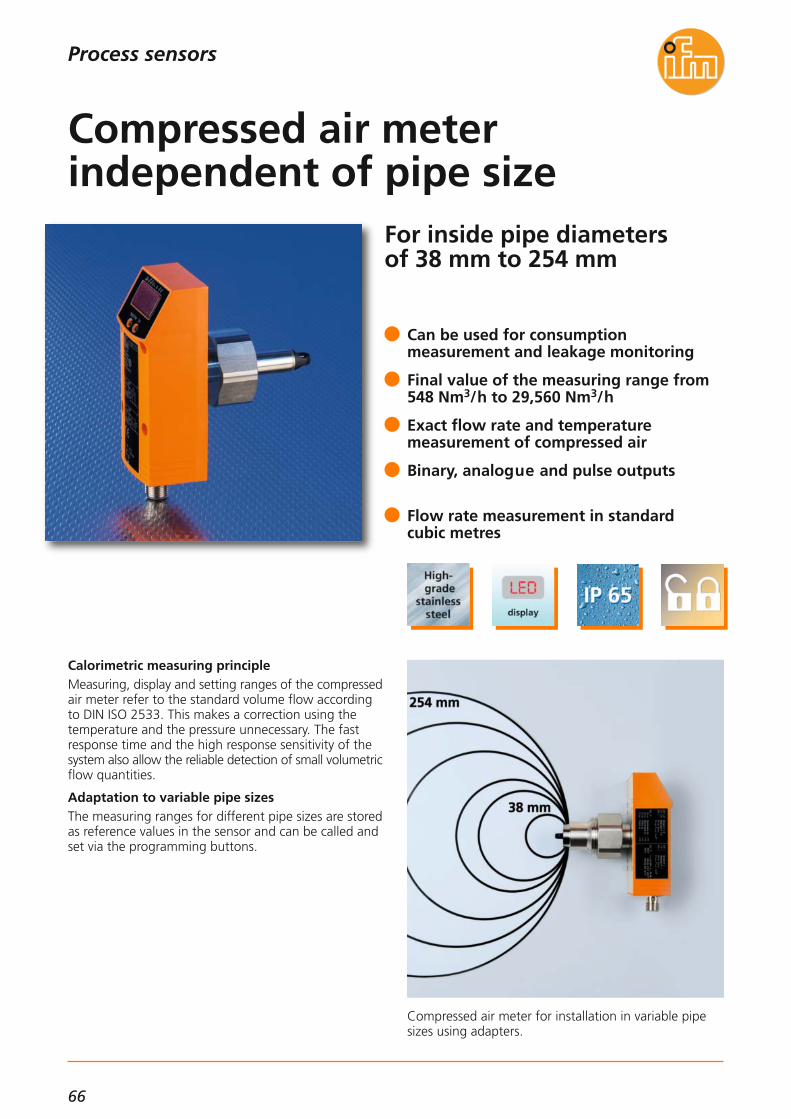
66
For inside pipe diameters of 38 mm to 254 mm
Compressed air meter for installation in variable pipesizes using adapters.
Calorimetric measuring principleMeasuring, display and setting ranges of the compressed air meter refer to the standard volume flow accordingto DIN ISO 2533. This makes a correction using thetemperature and the pressure unnecessary. The fast response time and the high response sensitivity of thesystem also allow the reliable detection of small volumetric flow quantities.
Adaptation to variable pipe sizesThe measuring ranges for different pipe sizes are storedas reference values in the sensor and can be called andset via the programming buttons.
Can be used for consumption measurement and leakage monitoring
Final value of the measuring range from548 Nm3/h to 29,560 Nm3/h
Exact flow rate and temperature measurement of compressed air
Binary, analogue and pulse outputs
Flow rate measurement in standard cubic metres
Compressed air meter independent of pipe size
Process sensors

67
INN
OV
ATI
ON
S
(04.2014)
Flow sensors / flow meters
Dimensions
111,5
96,5
451
2
3
6252,8
12
100
M12
x1
36
For further technical details please visit: www.ifm.com
Further technical data
TypeSD0523
Connection technology
Type Description Order no.
Socket, M12,2 m black, PUR cable EVC004
Socket, M12,5 m black, PUR cable EVC005
Socket, M12,10 m black, PUR cable EVC006
Process sensors
Accessories
Type Description Orderno.
Welding adapter, G 1 female – Ø 20 mm E40195
Operating voltage [V] 18...30 DC
Analogue output [mA] 4...20
Housing materials
PBT-GF 20; PC (polycarbonate);
stainless steel(304/1.4301);
FPM
Materials wetted parts
High-grade stainless steel(316/1.4401),
ceramics; glass passivated;PEEK (polyether-
etherketone);polyester; FPM;
aluminium; anodised
Medium temperature [°C] 0...60
Ambient temperature [°C] 0...60
Response time [s] < 0.1 (dAP = 0)
Pressure resistance [bar] 16
Protection rating, protection class IP 65, III
Connection M12 connector
Short-circuit protection, pulsed •
Current rating [mA] 2 x 250
Reverse polarity / overload protection • / •
Final value of the measuring range
[Nm3/h]
Repeatability
[% of the measured value]
Measuring accuracy
[% of the final value]
Processconnection
Order no.
Application: compressed air in industrial use, air quality (DIN 8573-1)
548...29,560 ± 1.5 ± (6 % MV + 0.6 % VMR) * G 1 female SD0523
1) Programming buttons2) 4-digit alphanumeric display3) Status LEDs
L+
L3 BU
4 BK
2 WH
1 BN
Out 1Out 2
4:2:
L
L+
3 BU
4 BK
2 WH
1 BN
Out 1Out 2
4:2:
Wiring diagram
Measuring / setting range
0 20 40 60 80 100 120 140 160 180 200 220 240 260
6000
9000
12000
15000
18000
21000
24000
27000
30000[Nm3/h]
2
1
[mm]
3000
Final value of the measuring range (1) referred to the internal pipe diameter (2)
*) For D = 72 mm, T = 22 °C and standard volume flows of 50...850 Nm3/h

68
Binary and analogue volumetric flow sensors for liquids
Mechatronic sensor in the coolant circuit of an induction furnace.
Mechatronic flow sensorThe flow sensor works to the principle of spring-supported piston: The piston, located in the valve seatin the housing, is lifted by the flowing medium againstthe spring resistance.For binary signal output the piston position is detectedby an inductive sensor. Analogue sensors however detect the position by means of a magnetic-field sensor.The spring resistance forces the piston to return to itsoriginal position with decreasing flow. This ensures position-independent installation of the flow sensorpreventing backflow.The switch points can be easily set and fixed via a setting screw. The robust mechanical design ensures usein harsh environments. The units are maintenance-free.
Volumetric flow quantities: 15 l/min,25 l/min, 50 l/min, 100 l/min, 200 l/min
Fast response time ≤ 10 ms
Easy handling: Switch points can be(pre)set continuously
Variable R or G process connection
Pressure ranges up to 25 bar, medium temperature up to 180 °C
Robust mechatronic flow sensor
Process sensors

69
INN
OV
ATI
ON
S
(04.2014)
Flow sensors / flow meters
Common technical data
Operating voltage [V] 24 DC (-15 % / +10 %)
Short-circuit protection •
Materials (wetted parts) SBY3
stainless steel(301/1.4310),
nickel-plated brass,PPS, PP, O-ring: FPM
Materials (wetted parts) SBT6
stainless steel(316/1.4401),
nickel-plated brass,PPS, O-ring: FPM
Materials (wetted parts) SBY4
stainless steel(316/1.4401),
nickel-plated brass,PPS, PP, O-ring: FPM
Ambient temperature [°C] 0...60
Reverse polarity / overload protection • / •
TypeSBY, SBT
Protection rating, protection class IP 65 / IP 67, III
3
L+
L
1
4
Wiring diagram
Connection technology
Type Description Orderno.
M12 socket,2 m black, PUR cable EVC001
M12 socket,5 m black, PUR cable EVC002
M12 socket,2 m orange, PVC cable EVT064
M12 socket,5 m orange, PVC cable EVT001
All data refer to water.
For further technical data please go to: www.ifm.com
L+
L
1
2
3
SBY3 SBY4, SBT6
Process sensors
Accuracy [% of the final value] ± 5
Measuring range
[l/min]
Hysteresis
[l/min]
Responsetime[s]
Medium temperature
[°C]
Pressure loss
[bar]
Orderno.
M12 connector · output function NO · electrical design DC pnp · binary
1...15 0.2...1 ≤ 0.01 0...85 SBY332
Process connection
Rp 3/4
1...25 0.5...2 ≤ 0.01 0...85 SBY333Rp 3/4
2...50 1...3 ≤ 0.01 0...85 SBY334Rp 3/4
5...100 3...6 ≤ 0.01 0...85 SBY346Rp 1
20...200 5...10 ≤ 0.01 0...85 SBY357Rp 1 1/2
Application: liquids
M12 connector · electrical design DC PNP · analogue 4...20 mA
1...25 – ≤ 0.01 -10...100 SBY433Rp 3/4
Silicone cable with M12 connector · electrical design DC · analogue 4...20 mA
0.3...25 – ≤ 0.01 10...180 SBT633Rp 3/4
2...50 – ≤ 0.01 -10...100 SBY434Rp 3/4
4...100 – ≤ 0.01 -10...100 SBY446
8...200 – ≤ 0.01 -10...100 SBY457
0.3...50 – ≤ 0.01 10...180 SBT634Rp 3/4
Rp 1
Rp 1 1/2
0.05...0.24
0.04...0.44
0.05...0.72
0.05...1.05
0.05...0.31
0.02...0.22
0.02...0.22
0.06...0.29
0.06...0.29
0.1...0.5
0.14...0.52

70
Process sensors
Flush-front temperature sensors for the food industry
Flush mountFlush-front temperature sensors from ifm are now available for applications such as agitators or piggingsystems.
Quick and easy to useThanks to the integrated process connection with G 1/2sealing cone, the compact design allows quick and easy installation. Versions with integrated transmitter(4...20 mA) or Pt100 output are available.
Hygienic and robustThe one-piece full-metal housing has been specially developed for particularly harsh applications. Electrical connection is made using M12 connectors.
Hygienic and robust: high-grade stainless steel (316L/1.4404) and IP 69K
Space saving compact design
Selectable: 4...20 mA transmitter or Pt100
Quick and easy: G 1/2 process connectionwith sealing cone
Flexible: adapter concept for all commonprocess connections
Temperature measurement –flush and hygienic

71
INN
OV
ATI
ON
S
(11.2014)
Process sensors
For further technical details please visit: www.ifm.com
Temperature sensors
Connection technology
Type Description Orderno.
Socket, M12, 4-pole,5 m orange, PVC cable EVT001
Socket, M12, 4-pole,2 m orange, PVC cable EVT064
Socket, M12, 4-pole,5 m orange, PVC cable EVT004
Socket, M12, 4-pole,2 m orange, PVC cable EVT067
Accessories
Type Description Orderno.
Operating voltage [V DC] 18...32
Pressure resistance [bar] 0...16
Ambient temperature [°C] -25...80
Housing materialhigh-grade st. steel
(316L/1.4404),PEEK
Further technical data
Maximum measuring range [°C] -50...140
Protection IP 69K
Welding adapter ball, G 1/2 E30055
Welding adapter collar, G 1/2 E30056
Pipe fitting, G 1/2 – DN25 SMS, high-grade st. steel / 316L / 1.4404 E33430
Sealing plug, G 1/2, high-grade st. steel / 316L / 1.4435 E43308
Dynamic response [s] 10 / 40
Pipe fitting,G 1/2 female – DIN 11851 DN25 E43304
Pipe fitting,G 1/2 female – DIN 11851 DN40 E43305
Clamp adapter, G 1/2 female – Varivent D50 E43306
Clamp adapter, G 1/2 female – Varivent D68 E43307
Process connection Temperature range
[°C]
Temperature transmitter 4...20 mA
G 1/2, flush TA3597
Temperature sensor with direct Pt100 evaluation
G 1/2, flush
0...100
-50...140 TM4599
Orderno.
Clamp adapter, G 1/2 female – clamp 1"–1.5" E33401
Clamp adapter, G 1/2 female – clamp 2" E33402
Welding adapter,cylindrical, for tanks, G 1/2 E43300
Welding adapter,cylindrical, for pipes, G 1/2 E43301

72
Process sensors
Thermowells for all common process connectionsand installation depths
Why is a thermowell required?Aggressive media, high pressures and flow speedsmake the use of thermowells necessary. Thermowells protect temperature sensors from such influences and make it possible to replace sensors inthe running process. So, a calibration of the sensors is possible at any time.
UniversalThe ifm thermowells are suited for all temperature probes with a diameter of 6 mm. Market common process connections are designed for use in hygienicand industrial applications.
Convenient: sensor calibration withoutprocess interruption
Special: for industrial and hygienic applications
Robust: sensor protection in harsh applications
Suited: for all Ø 6 mm temperature probes
Flexible: installation depths of 30...330 mm
Extra protection for temperature sensors

73
INN
OV
ATI
ON
S
(11.2014)
Process sensors
For further technical details please visit: www.ifm.com
Temperature sensors
Device connection
Installation depth EL [mm]
Sensor Thermowell
G 1/2 E37810100
G 1/2 E37820150
G 1/2 E37830250
G 1/2 E37850350
Orderno.
G 1/2 E37910
G 1/2 E37920
G 1/2 E37930
G 1/2 E37950
G 1/2 E37430250
G 1/2 E37450350
Ø 6 mm E37603
Ø 6 mm E37613
Ø 6 mm E37623
Ø 6 mm E37643
Ø 6 mm E37663
G 1/2 conical E37511
G 1/2 conical E37521
G 1/2 conical E37411
G 1/2 conical E37421
G 1/2 conical E37431
G 1/2 E37600
G 1/2 E37610
G 1/2 E37620
G 1/2 E37640
64
115
191
267
191
267
33
83
128
233
333
68
118
49
99
149
27
74
124
224
50
100
150
250
350
100
150
50
100
150
50
100
150
250
Process connection Tri-Clamp 1.5" for type: TA24, TT12, TT32, TM44, TD22
Process connection Tri-Clamp 2" for type: TA24, TT12, TT32, TM44, TD22
Welding thermowell, weld-in process connection for type: TT32, TD22
Clamp fitting, process connection G 1/2 for type: TT92, TT02, TT12, TT22, TT32, TD22
Hygienic thermowell, process connection G 1/2 conical for type: TM45, TD25
Welding clamp adapter, ball process connection 34 mm Ø for type: TM45, TD25
Screw-in thermowell, process connection G 1/2 for type: TA24, TT02, TT12, TT22, TT32, TM44, TD22
63
ELBL
6,4
44,5
12,7
6,6
19
38,1 1
26,7
½" NPS
63
ELBL
6,4
44,5
12,7
6,6
19
38,11
26,7
½" NPS
38,1
44,5 ELBL
6,4
6,6
16
½" NPS
7 9
27 G ½
ELBL
13
1M4
27
G ½
G ½
97 18
72 ELBL
2,5
37
2,5
41 ELBL
G ½
793034
16,6
27
G ½
G ½
28 ELBL
1
97
1) 1.5" Clamp (ISO 2852)
1) 2" Tri-Clamp (ISO 2852)
100
150
250
350
64
115
191
267

74
Less is more
Even for small local control cabinets All new SmartLine modules feature a housing that isonly 25 mm wide, so they will easily fit into a small panel.The transistor module is only 52 mm deep, so requiresvery little space, making it ideal for local control panels.At just 108 mm deep and 25 mm wide the relay module also won’t take up much space in a classic control cabinet.
Powerful and flexibleThe supplied cage clamps allow easy and efficient universal wiring. Double terminals help the user to loopthrough the power supply. Sensor supply and the out-puts of the transistor version are rated with 1 A, therelay modules switch up to 6 A.
Powerful relay switches up to 6 A
4 relays in slim design of only 25 mm
Low-profile transistor module
Plug supplied with the unit
Double terminals for the supply
Small and powerful – AS-i Smart-Line module for control cabinets
Industrial communication

75
INN
OV
ATI
ON
S
(11.2014)
The products
Orderno.
4DI 4DO transistor [1A], depth 52 mm AC3200
4DI AUX 4DO transistor [1A], depth 52 mm AC3201
4DI 4DO relay [6A], depth 108 mm AC3220
4DI AUX 4DO relay [6A], depth 108 mm AC3221
Dimensions
Operating voltage [V DC] 16...30
Sensor supply inputs via AS-i
Digital inputs 4
Max. current load [mA]for all inputs total 200
Current rating [mA]per output 1000
Current rating [mA]per module 4000
AS-i profile S-7.A.7
AS-i specification 2.11 + 3.0
Extended addressing mode •
Ambient temperature [°C] -25...65
Voltage range [V DC]separate to PELV 24 (20...30)
Digital transistor outputs 4
SmartLine module AC3200
AS-Interface I /O moduleIndustrial communication
Type Description
Further technical data
SmartLine: 25 mm width, A/B slaves
For further technical details please visit: www.ifm.com
Accessories
Orderno.
AS-i addressing unit AC1154
Type Description
Addressing cables E70213
AS-i power supply 8 A AC1258
24 V DC PELV power supply DN4013
Advantages and customer benefits
• Transistor versionThe transistor version with 2 modules and 4 inputsand 4 outputs has an extremely flat and small housing for small control cabinets. The inputs are either supplied with up to 200 mA via the AS-voltage as usual or via an external PELVvoltage source. They are then rated up to 1 A. Bothunits can switch 1 A per output.
• Relay versionThe relay version provides 4 relay outputs with awidth of only 25 mm – two changeover contacts andtwo NO contacts – with a current rating of up to 6 A.The four inputs are either supplied via an AS-i or anexternal PELV voltage source.
• Extended addressing modeUp to 62 units can be connected to a master of specification 3.0 with M4 profile as A or B slaves. Themodules can be addressed either prior to installationwithout voltage or when connected and wired via theaddressing socket.
1) Connector with cage clamp connection2) Label3) Addressing socket4) DIN rail adapter
10825,4
9312
3,2
1
4 x LED
4 x LED
3
2
4
35,5
AC3220, AC3221
25,4
95,4
129,
3
1
4 x LED
4 x LED
3
2
59,3
71
4
35,5
AC3200, AC3201
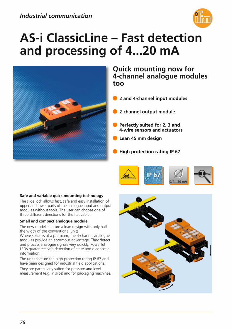
76
Quick mounting now for 4-channel analogue modulestoo
Safe and variable quick mounting technologyThe slide lock allows fast, safe and easy installation ofupper and lower parts of the analogue input and output modules without tools. The user can choose one ofthree different directions for the flat cable.
Small and compact analogue moduleThe new models feature a lean design with only halfthe width of the conventional units. Where space is at a premium, the 4-channel analoguemodules provide an enormous advantage. They detectand process analogue signals very quickly. PowerfulLEDs guarantee safe detection of state and diagnosticinformation.The units feature the high protection rating IP 67 andhave been designed for industrial field applications.They are particularly suited for pressure and level measurement (e.g. in silos) and for packaging machines.
2 and 4-channel input modules
2-channel output module
Perfectly suited for 2, 3 and 4-wire sensors and actuators
Lean 45 mm design
High protection rating IP 67
AS-i ClassicLine – Fast detectionand processing of 4...20 mA
Industrial communication
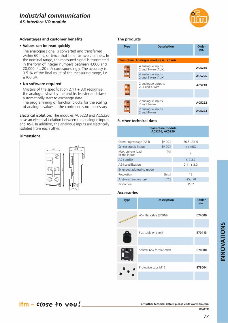
77
INN
OV
ATI
ON
S
(11.2014)
The products
Orderno.
4 analogue inputs, 2 and 3-wire (AUX) AC5216
4 analogue inputs, 2 and 4-wire (AUX) AC5226
2 analogue outputs, 2, 3 and 4-wire AC5218
2 analogue inputs, 2 and 3-wire AC5222
2 analogue inputs, 2 and 4-wire AC5223
Dimensions
Sensor supply inputs [V DC] via AUX
Operating voltage (AS-i) [V DC] 26.5...31.6
Max. current load [A]of the inputs 2
Extended addressing mode –
Resolution [bits] 12
Ambient temperature [°C] -25...70
Protection IP 67
AS-i specification 2.11 + 3.0
AS-i profile S-7.3.E
ClassicLine module AC5216, AC5226
AS-Interface I /O moduleIndustrial communication
Type Description
Further technical data
ClassicLine: Analogue module 4…20 mA
For further technical details please visit: www.ifm.com
Accessories
Orderno.
AS-i flat cable (EPDM) E74000
Type Description
Flat cable end seal E70413
Splitter box for flat cable E70600
Protective caps M12 E73004
Advantages and customer benefits
• Values can be read quicklyThe analogue signal is converted and transferred within 60 ms, or twice that time for two channels. Inthe nominal range, the measured signal is transmitted in the form of integer numbers between 4,000 and20,000, 4...20 mA correspondingly. The accuracy is0.5 % of the final value of the measuring range, i.e.±100 μA.
• No software requiredMasters of the specification 2.11 + 3.0 recognise the analogue slave by the profile. Master and slaveautomatically start to exchange data. The programming of function blocks for the scalingof analogue values in the controller is not necessary.
Electrical isolation: The modules AC5223 and AC5226 have an electrical isolation between the analogue inputs and AS-i. In addition, the analogue inputs are electrically isolated from each other.
45
103
40,244,7
25,8
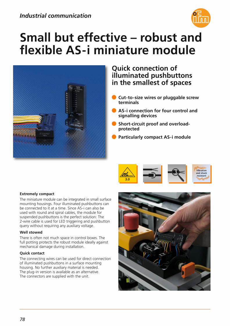
78
Quick connection of illuminated pushbuttons in the smallest of spaces
Extremely compactThe miniature module can be integrated in small surfacemounting housings. Four illuminated pushbuttons canbe connected to it at a time. Since AS-i can also beused with round and spiral cables, the module for suspended pushbuttons is the perfect solution: The 2-wire cable is used for LED triggering and pushbuttonquery without requiring any auxiliary voltage.
Well stowedThere is often not much space in control boxes. The full potting protects the robust module ideally againstmechanical damage during installation.
Quick contactThe connecting wires can be used for direct connectionof illuminated pushbuttons in a surface mounting housing. No further auxiliary material is needed. The plug-in version is available as an alternative. The connectors are supplied with the unit.
Cut-to-size wires or pluggable screw terminals
AS-i connection for four control and signalling devices
Short-circuit proof and overload-protected
Particularly compact AS-i module
Small but effective – robust andflexible AS-i miniature module
Industrial communication

79
INN
OV
ATI
ON
S
(04.2014)
For further technical details please visit: www.ifm.com
Products
Order no.
Active AS-i module:4 inputs / 4 outputs,AS-i profile: S-7.A.7
AC2750
Active AS-i module:4 inputs / 3 outputs,AS-i profile: S-7.A.E
AC2751
Active AS-i module:4 inputs / 4 outputs,AS-i profile: S-7.A.7
AC2752
Active AS-i module:4 inputs / 3 outputs,AS-i profile: S-7.A.E
AC2753
Dimensions
12 76,6
31,1
Example AC2752
Advantages and customer benefits
• Energy and data on one cableThe AS-i cable supplies the connected LEDs andpushbuttons with up to 150 mA without requiringfurther auxiliary voltage. All inputs and outputs areshort-circuit proof.
• A/B addressing saves addressesUp to 62 participants can be connected. 248 inputsand 248 outputs are possible for one AS-i network.
• On-site diagnosisThe module indicates the condition of all inputs and outputs as well as the energy supply and thecommunication status by means of LEDs.
Operating voltage (AS-i) [V DC] 18...31.6
Total current consumption [mA]from AS-i < 180
Overload protection •
Ambient temperature [°C] -25...55
AS-i specification 2.11 + 3.0
Extended addressing mode •
Housing material Potted PC
Short-circuit protection •
Current rating per module [mA] 150
Installation module digital inputs, digital outputs
AS-Interface I/O modulesIndustrial communication
Type Description
Common technical data
Connection: PVC strand; 12 x 0.2 m
Connection: Screw terminals

80
Easy as using a smartphone!Individual connection to a PLCby means of reloadable apps
Until now: complex programmingModern sensors offer more and more intelligent functions that can also be made available to the PLC via interfaces like IO-Link or TCP/IP.To use them, the PLC programmer has to individuallyimplement the functionalities in the PLC. This is verytime-consuming and costly, especially when it comes to implementing the required user interfaces.
From now on: fit for Industry 4.0 – ifm System SolutionsWith the new ifm System Solution Apps ifm electronichas developed a system which is easy to create. It allows process data from different sensors to be transmitted tocommon fieldbus systems, and their parameters are easily accessible. For this purpose, ifm now offers tailored apps whichcan be loaded into the ifm fieldbus gateway withoutany programming software.
Fast and easy integration of intelligentsensors into the PLC world
No special PC software required, an internet browser is sufficient
PLC connection via the fieldbus protocolsProfinet, Profibus, EtherNet/IP and others
Smart additional functions tailored to thesensors selected
Straightforward web configuration instead of time-consuming and costly programming
Industry 4.0 made easy – apps instead of expensive programming
Industrial communication
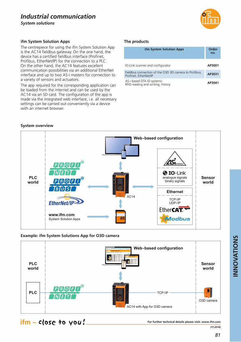
81
INN
OV
ATI
ON
S
(11.2014)
The products
Orderno.
IO-Link scanner and configurator
Fieldbus connection of the O3D 3D camera to Profibus,Profinet, EtherNet/IP
AS-i based DTA ID systems: RFID reading and writing, history
System solutionsIndustrial communication
ifm System Solution Apps
For further technical details please visit: www.ifm.com
ifm System Solution AppsThe centrepiece for using the ifm System Solution Appis the AC14 fieldbus gateway. On the one hand, thedevice has a certified fieldbus interface (Profinet, Profibus, EtherNet/IP) for the connection to a PLC. On the other hand, the AC14 features excellent communication possibilities via an additional EtherNetinterface and up to two AS-i masters for connection toa variety of sensors and actuators.The app required for the corresponding application canbe loaded from the internet and can be used by theAC14 via an SD card. The configuration of the app ismade via the integrated web interface, i.e. all necessarysettings can be carried out conveniently via a devicewith an internet browser.
System overview
Example: ifm System Solutions App for O3D camera
Web-based configuration
PLCworld
Sensorworld
www.ifm.comSystem Solution Apps
AC14
analogue signalsbinary signals
Ethernet
TCP/IPUDP/IP
Web-based configuration
AC14 with App for O3D camera
PLCworld
Sensorworld
PLC TCP/IP
O3D camera
AP3001
AP3031
AP3041

82
Wide range of interfacesNew: TCP/IP version
Always know what’s going onifm electronic has placed RFID systems on the marketthat are unbeatable with regard to • Price / performance ratio, • Ease of installation and • Robustness This product range now offers new functions for Profibus, Profinet, EtherNet /IP and TCP/ IP.
Large antenna selectionAnother innovation is the robust antennas in M12, M30 and rectangular housing for automation and conveyingtechnology. Industrially compatible M12 plugs and connection tech-nology from ifm electronic guarantee quick and simpleconnection of antennas and sensors without complica-ted wiring.
Integrated web server for device setup,diagnosis and monitoring
Connection of RFID antennas, sensors oractuators
Robust RFID antennas with long writing / reading distance
RFID antennas for flush and non-flush installation
Simple connection of the antennas via cables up to 20 m
Simple, low price and flexible:RFID for machine control
Identification systems
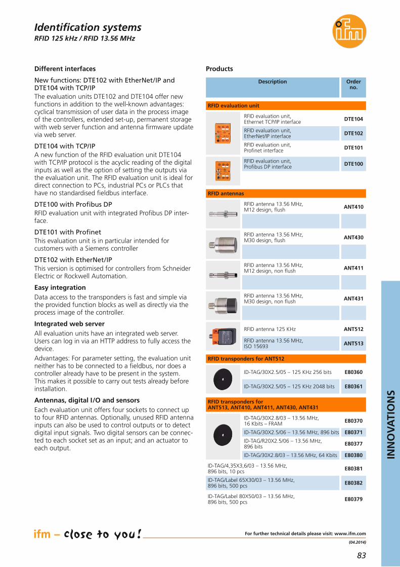
83
INN
OV
ATI
ON
S
(04.2014)
RFID 125 kHz / RFID 13.56 MHz
Different interfaces
New functions: DTE102 with EtherNet/IP andDTE104 with TCP/IPThe evaluation units DTE102 and DTE104 offer newfunctions in addition to the well-known advantages: cyclical transmission of user data in the process imageof the controllers, extended set-up, permanent storagewith web server function and antenna firmware updatevia web server.
DTE104 with TCP/IPA new function of the RFID evaluation unit DTE104with TCP/IP protocol is the acyclic reading of the digitalinputs as well as the option of setting the outputs viathe evaluation unit. The RFID evaluation unit is ideal fordirect connection to PCs, industrial PCs or PLCs thathave no standardised fieldbus interface.
DTE100 with Profibus DPRFID evaluation unit with integrated Profibus DP inter-face.
DTE101 with ProfinetThis evaluation unit is in particular intended for customers with a Siemens controller
DTE102 with EtherNet/IPThis version is optimised for controllers from SchneiderElectric or Rockwell Automation.
Easy integrationData access to the transponders is fast and simple viathe provided function blocks as well as directly via theprocess image of the controller.
Integrated web serverAll evaluation units have an integrated web server.Users can log in via an HTTP address to fully access thedevice.Advantages: For parameter setting, the evaluation unitneither has to be connected to a fieldbus, nor does acontroller already have to be present in the system. This makes it possible to carry out tests already beforeinstallation.
Antennas, digital I/O and sensorsEach evaluation unit offers four sockets to connect upto four RFID antennas. Optionally, unused RFID antennainputs can also be used to control outputs or to detectdigital input signals. Two digital sensors can be connec-ted to each socket set as an input; and an actuator toeach output.
For further technical details please visit: www.ifm.com
Identification systems
Description Order no.
DTE102RFID evaluation unit, EtherNet/IP interface
DTE104RFID evaluation unit, Ethernet TCP/IP interface
DTE101RFID evaluation unit, Profinet interface
ANT512RFID antenna 125 KHz
ANT513RFID antenna 13.56 MHz,ISO 15693
E80360ID-TAG/30X2.5/05 – 125 KHz 256 bits
E80361ID-TAG/30X2.5/05 – 125 KHz 2048 bits
RFID evaluation unit
RFID antennas
Products
DTE100RFID evaluation unit, Profibus DP interface
RFID transponders for ANT512
ANT410RFID antenna 13.56 MHz,M12 design, flush
ANT430RFID antenna 13.56 MHz,M30 design, flush
ANT411RFID antenna 13.56 MHz,M12 design, non flush
ANT431RFID antenna 13.56 MHz,M30 design, non flush
RFID transponders for ANT513, ANT410, ANT411, ANT430, ANT431
E80370ID-TAG/30X2.8/03 – 13.56 MHz, 16 Kbits – FRAM
E80371ID-TAG/30X2.5/06 – 13.56 MHz, 896 bits
E80377ID-TAG/R20X2.5/06 – 13.56 MHz, 896 bits
E80380ID-TAG/30X2.8/03 – 13.56 MHz, 64 Kbits
E80381ID-TAG/4,35X3,6/03 – 13.56 MHz, 896 bits, 10 pcs
E80382ID-TAG/Label 65X30/03 – 13.56 MHz, 896 bits, 500 pcs
E80379ID-TAG/Label 80X50/03 – 13.56 MHz, 896 bits, 500 pcs

84
The UHF system withintegrated EtherNet/IP
The new RFID evaluation unitThe new evaluation unit DTE820 is a combination ofantenna and evaluation unit, preferably used in case ofscattered reading points or large antenna distances.
The UHF antenna conceptThe ultra low and low range antennas are ideal for sen-sing in the near field. In order to achieve high selectivity,small designs are used as they allow short reading ranges.The mid range antenna is chosen for applications in thenear / far field with reading ranges of up to 2 m. Thenew antenna ANT815 has been optimised for distancesfrom 0.2 to 1 m.The wide range antennas have been developed for applications in the far field where reading ranges of upto 10 m are required.
Best performance, compact design withpower over Ethernet (PoE)
UHF write/read unit with 4 antennaterminals and digital I /Os
Ultra low, low, mid range and wide rangeantennas for every application
Ethernet TCP/IP interface for parametersetting
Industrially compatible protection ratingIP 65 / IP67
Systematic transparency – forproduction and logistics
Identification systems

85
INN
OV
ATI
ON
S
(11.2014)
RFID UHF
ApplicationsOwing to its application-specific antennas, the newUHF system platform from ifm electronic is widely usedin automation technology, e.g. in the fields of produc-tion, logistics and conveyor technology.Goods, packaging or pallets but also individual productscan be identified without contact.The UHF RFID has been optimised for applications in• production control• asset management• material flow control• track & traceThe standardised Ethernet interface with M12 connec-tion enables quick and easy integration into the higherlevel automation or process control. Current is supplieddirectly via an M12 connection.The connected sensors or actuators to be triggered aresupplied via the evaluation unit.A robust housing with protection rating IP 65 and awide temperature range ensure the use of the readersin harsh industrial environments.
Description Orderno.
The products
Type Description Orderno.
Accessories
DTE810RFID UHF reader, EtherNet/IP,4 DI / 4 DO, EU/ETSI
DTE910RFID UHF reader, EtherNet/IP,4 DI / 4 DO, US/FCC
ANT805RFID UHF ultra low range antennaEU/ETSI/US/FCC
ANT810RFID UHF low range antennaEU/ETSI
ANT820RFID UHF mid range antenna100°/100° EU/ETSI
ANT815RFID UHF short mid range antennaEU/ETSI/US/FCC
ANT830RFID UHF wide range antenna70°/70° EU/ETSI
ANT910RFID UHF low range antennaUS/FCC
ANT930RFID UHF wide range antenna70°/70° US/FCC
RFID UHF reader, dimensions 270 x 234 x 68 mm
RFID UHF antennas, dimensions 90 x 60 x 18 mm
DTE800RFID UHF reader, Ethernet TCP/IP,2 DI / 2 DO, EU/ETSI
DTE900RFID UHF reader, Ethernet TCP/IP,2 DI / 2 DO, US/FCC
RFID UHF antennas, dimensions 150 x 122 x 35 mm
RFID UHF antennas, dimensions 270 x 270 x 45 mm
Common technical dataRFID UHF reader
Operating voltage [V] 24 DC ± 10 %
Current rating outputs [mA] 500 (per switching output)
Current consumption [mA] < 700
Ambient temperature [°C] -25...55
Protection rating, protection class IP 65
Material metal housing with plastic cover
Switching inputs 2 or 4
Switching outputs 2 or 4
Frequency range EU/ETSI [MHz] 865...870
Frequency range US/FCC [MHz] 902...928
Air interface ISO 18000-6C
Range [m] 10, depending on the tag
Antenna concept external
Antenna terminal, external 4 x TNCreverse 50 Ω
Ethernet, cross-over patch cable,2 m, PUR cable, M12 / RJ45 E11898
Ethernet, cross-over patch cable,10 m, PUR cable, M12 / RJ45 E12204
RFID UHF transponderID tag/D50X3.3/04 E80350
RFID UHF on metal transponderID tag/D55X13/04 E80351
RFID UHF transponderID tag/R30X10/04 E80353
RFID UHF transponderID tag/R40X10/04 E80354
Installation kit for wide range antenna E80340
Jumper for antennas RG58, 3 m E80330
Jumper for antennas RG58, 6 m E80331
Jumper for antennas RG58, 10 m E80332
Jumper for antennas RG58, 15 m E80333
For further technical data please go to: www.ifm.com
DTE820RFID UHF reader, Ethernet/PoE,3 DI / 3 DO (GPIOs), EU/ETSI
RFID UHF reader, dimensions 156 x 139.3 x 63 mm
Identification systems

86
Improved functions for all ifm multicode readers
The ifm multicode reader Independent of the orientation and the number ofcodes, the high-performance algorithms automaticallydecode 1D or 2D codes. The evaluation has been extended by the quality parameters for 1D codes.
Especially for industrial applicationsWith its integrated lighting, different interfaces andlarge variety of operating distances and field of viewsizes, the ifm multicode reader is suited for a largenumber of industrial applications.
UpgradeEvaluation time reduced by up to 100 ms. Optimised autodetect function for code recognition.
Up to 50 % faster evaluation time
Extended 2D library with micro QR andAtec code
Extended 1D library with MSI and GS1 codes
New: with bar code quality parameters
The new compact multicode reader – Fast – Robust
Identification systems

87
INN
OV
ATI
ON
S
(11.2014)
1D/2D code readers
Type of sensor:CMOS image sensor, black/white, VGA resolution 640 x 480
Readable 2D codesECC200, PDF-417, QR, Micro QR, AztecReadable 1D codesInterleaved 2-of-5, Industrial 2-of-5, Code 39Code 128, Pharmacode, Code 93, CodabarEAN13, EAN13-Add-On 2, EAN13-Add-On 5EAN8, EAN8-Add-On 2, EAN8-Add-On 5UPC-A, UPC-A Add-On 2, UPC-A Add-On 5UPC-E, UPC-E Add-On 2, UPC-E Add-On 5GS1 DataBar Omnidirectional, GS1 DataBar TruncatedGS1 DataBar Stacked, GS1 DataBar Stacked OmniGS1 DataBar Limited, GS1 DataBar ExpandedGS1 DataBar Expanded Stacked
Wide range of applicationsThe ifm multicode reader is used in a wide range of industrial applications. It provides product tracking, production control or product identification in the mostvaried areas: automotive, electronic and food industries, conveyor technology or in machine tools and printingmachines. The standardised process interfaces RS-232, EthernetTCP/IP and EtherNet/IP ensure fast and easy integrationin industrial control technology.
Type Description Orderno.
Accessories
For further technical details please visit: www.ifm.com
Identification systems
Operating software for multicode reader E2I200
OPC server for multicode reader E2I210
High-grade stainless steel mounting setfor rod mounting, Ø 12 mm E2D110
High-grade stainless steel mounting setfor rod mounting, Ø 14 mm E2D112
Clamp,high-grade stainless steel, Ø 12 mm E21110
Clamp,high-grade stainless steel, Ø 14 mm E21109
Clamp linking ring,high-grade stainless steel E21076
Protective cover/diffuser E21165
Protective plastic cover E21166
Protective glass cover E21168
Laser protection pane E21169
Connection technology
Type Description Orderno.
Socket, M12,2 m PUR cable, 8 poles E11950
Socket, M12,5 m, PUR cable, 8 poles E11807
Ethernet, cross-over patch cable,2 m, PUR cable, M12 / RJ45 E11898
Ethernet, screened patch cable,2 m, PUR cable, M12 / RJ45 E12090
Ethernet, cross-over patch cable,10 m, PUR cable, M12 / RJ45 E12204
Ethernet, cross-over patch cable,20 m, PUR cable, M12 / RJ45 E12205
Common technical data
Operating voltage [V] 24 DC ± 10 %
Current rating [mA] 100 (per switching output)
Current consumption [mA] < 300
Ambient temperature [°C] -10...50
Protection rating, protection class IP 67, III
CoverMaterial Front lens
LED window
diecast zincglass
polycarbonate
Trigger
external, 24 V PNP internal,RS-232 / TCP/IP,
EtherNet/IP
Switching outputs (configurable) max. 2 (configurable),100 mA
Connection external illumination 24 V DC PNP
Parameter / process data interface
Ethernet 10Base-T /100Base-TX, RS-232,
EtherNet/IP
Dimensions [mm] 80 x 42 x 53.5
Motion speed [m/s] ≤ 7
Field of view size [mm] red light
50 75 100
Operating distance [mm] Orderno.
O2I30020 x 14
O2I30246 x 32
28 x 20
61 x 44
36 x 26
77 x 56
200
68 x 50
140 x 100
Field of view size [mm] infrared
O2I30120 x 14
O2I30346 x 32
28 x 20
61 x 44
36 x 26
77 x 56
68 x 50
140 x 100
Field of view size [mm] red light
200 400 1000
Operating distance [mm] Orderno.
O2I30440 x 30 80 x 60 200 x 150
2000
400 x 300
Field of view size [mm] infrared
O2I30540 x 30 80 x 60 200 x 150 400 x 300
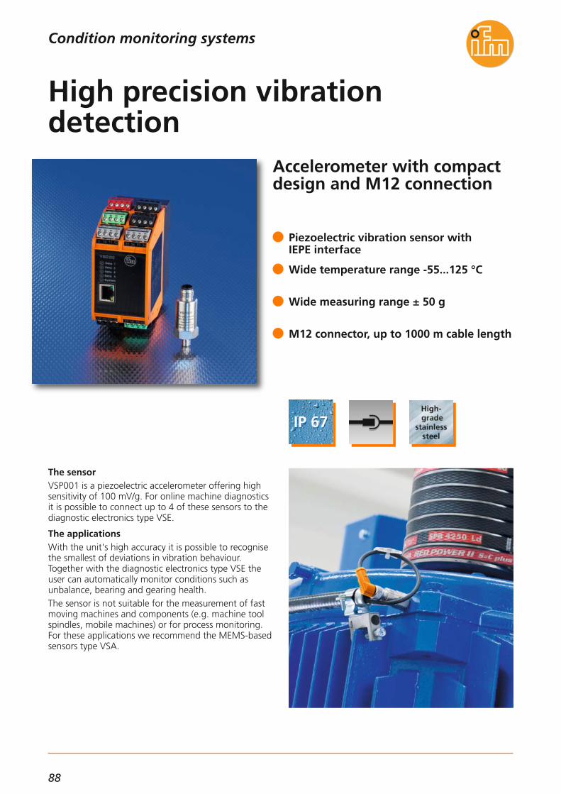
88
Accelerometer with compactdesign and M12 connection
The sensorVSP001 is a piezoelectric accelerometer offering highsensitivity of 100 mV/g. For online machine diagnosticsit is possible to connect up to 4 of these sensors to thediagnostic electronics type VSE.
The applicationsWith the unit's high accuracy it is possible to recognisethe smallest of deviations in vibration behaviour.Together with the diagnostic electronics type VSE theuser can automatically monitor conditions such as unbalance, bearing and gearing health.The sensor is not suitable for the measurement of fastmoving machines and components (e.g. machine toolspindles, mobile machines) or for process monitoring.For these applications we recommend the MEMS-basedsensors type VSA.
Piezoelectric vibration sensor with IEPE interface
Wide temperature range -55...125 °C
Wide measuring range ± 50 g
M12 connector, up to 1000 m cable length
High precision vibration detection
Condition monitoring systems

89
INN
OV
ATI
ON
S
(11.2014)
Technical data
Measuring range [g] ± 50
Measuring principle piezoelectric
Sensitivity 100 mV/g
Accuracy ± 5 %
Interface IEPE
Frequency range [Hz] 2...10000
Protection IP 67
Ambient temperature [°C] -55...125
Housing material stainless steel
Connection M12 connector
Vibration sensor VSP001
for connection to external diagnostic electronics type VSE
Dimensions
M12 x118,9
46,5
35,7
51/4''-28 UNF
19
Accessoires
Type Description Orderno.
Diagnostic electronics for vibration sensors type VSA / VSP, cabinet mounting; frequency selectivemachine monitoring of up to 4 measurement points, Ethernet interfaceTCP/IP, on-board time-stamped historyfunction, 2 switching outputs or 1 switching and 1 analogue output,counter function
VSE002
Diagnostic electronics for vibration sensors type VSA / VSP, cabinet mounting; frequency selectivemachine monitoring of up to 4 measurement points; Ethernet interfaceTCP/IP, on-board time-stamped historyfunction, 2 switching outputs or 1 switching and 1 analogue output, 8 further freely configurable I/O, counter function
VSE100
Wiring diagramme
43
2 1Pin 1: not usedPin 2: I outPin 3: not usedPin 4: L-
Connection technology
Type Description Orderno.
Socket M12 screened, 10 m black, PUR cable, 5-pole EVC534
Socket M12 screened, 30 m black, PUR cable, 5-pole EVC561
Socket M12 screened, 5 m black, PUR cable, 5-pole EVC533
Vibration monitoring systemsCondition monitoring systems
For further technical data please go to: www.ifm.com

90
Vibration transmitter for theATEX categories 3D/3G
Overall vibration monitoring of rotating equipmentsuch as fans, centrifuges etc.
Monitoring of machine healthThe vibration transmitter type VT monitors machinesand equipment according to ISO 10816. The sensormeasures the true RMS velocity to evaluate the overallmachine health.The values are then transmitted as an analogue signal(4...20 mA) directly to the PLC.
Use in hazardous areasPermanent vibration monitoring protects plant andequipment in hazardous areas ATEX category 3D/3Gfrom consequential damages which can be caused forexample by unbalance conditions of rotating compo-nents.
Quick and easy installationNo extra parameter software is required.
Permanent vibration monitoring accordingto ISO 10816
True RMS monitoring of overall velocity
2-wire loop powered
Robust stainless steel housing
Vibration monitoring in ATEX applications
Condition monitoring systems

91
INN
OV
ATI
ON
S
(04.2014)
Technical dataDimensions
M12 x1
22
63,2
5
4,5
1/4''-28 UNF
22
6,5
Connection cable, M12 socket / M12 coupling, 5 m black, PUR cable
EVC12A
Connection cable, M12 socket / M12 coupling, 10 m black, PUR cable
EVC13A
Wiring diagram
L+
L
1
2
Shock resistance [g] 400
Frequency range [Hz] 10...1000
Accuracy [%] < ± 3
Repeatability [%] < 0.5
Non-linearity [in %of the span] 0.25
Measuring range [mm/s] 4 mA = 0; 20 mA = 25
Measurand vibration velocity true RMS
Connection M12 connector
Housing material high-grade stainless steel 316L (1.4404)
Ambient temperature [°C] -20...60
Operating voltage [V] 9.6...32 DC
Analogue output [mA] 4...20
Load for [Ω]analogue output
max. (Ub - 9.6 V) x 50; 720 at Ub = 24V
ProtectionIP 67;
for use outside EX area IP 69K
Vibration transmitterVTV12A
Marking of the unit II 3D Ex tc IIIC T110°C Dc XII 3G Ex nA IIC T4 Gc X
Monitoring of overall velocity of machines and equipment according to ISO 10816 in ATEX area category 3D/3G
ATEX approval, group II, category 3G/2D
1) threaded adapter 1/4"-28 UNF / M8 x 1.25 mm2) threaded adapter 1/4"-28 UNFtightening torque 8 Nm
Vibration monitoring systemsCondition monitoring systems
For further technical data please go to: www.ifm.com
Connection technology
Type Description Order no.

92
Diagnostic electronics type VSE with extended functionality
High performance diagnostic electronicsVibration analysis protects machine components, tools and workpieces during machining against costlyconsequential damage and avoids scrap.In addition to the proven MEMS-based accelerometersfrom ifm electronic (type VSA), accelerometers, micro-phones, or force sensors which are based on the IEPEstandard can also be connected to the revised diagnostic electronics.Using the higher accuracy it is now possible to increasethe resolution of large measuring ranges.It is also possible to select different filters for processmonitoring and machine protection. Up to 32 countersprovide vibration characteristics, performance and run-time information which can be used to optimiseproduction.
Flexible connection of IEPE or vibrationsensors to all 4 dynamic channels
Different filters for real-time peak monitoring
Reaction times of < 1 ms and variablealarm levels for machine protection
Increased accuracy and improved internalmemory function
32 run-time and performance counters
From process monitoring to vibration analysis
Condition monitoring systems

93
INN
OV
ATI
ON
S
(04.2014)
Technical data
Operating voltage [V] 24 DC ± 20 %
Protection IP 20, III
Ambient temperature [°C] 0...70
Housing DIN rail 2"
Diagnostic electronicsVSE100
Dimensions
50
114
LEDs
2
1
105
35,5
Wiring diagram
L+ (24 V DC ±20 %)
1817
2019
1413
1615
2221
2423
65
87
21
43
109
1211
L-OU 1: switch/analog OU 2: switch
IN 1 (0/4...20 mA / pulse)GND 1IN 2 (0/4...20 mA / pulse)GND 2
1234
BNWHBUBK
4321
BKBUWHBN
I/O 7
3029
3231
3433
3635
2625
2827
4344
4142
4748
4546
3940
3738
GNDI/O 8GND
I/O 5GNDI/O 6GND
I/O 1GNDI/O 2GND
I/O 3GNDI/O 4GND
U-OUT (0...10 V)GND
U-IN 1 (0...10 V)GND 1U-IN 2 (0...10 V)GND 2
1234
BNWHBUBK
1234
BNWHBUBK
Data interface Ethernet TCP/IP,(10 / 100 MBits)
Counter function integrated
History function integrated
1) Ethernet interface2) Combicon connector with screw connectors (optional)
Accessories
Parameter software VES003
octavis OPC Server SoftwareNo. connections: 25, 50, 75, 100, 1000 German / English
VOS001VOS002VOS003VOS004VOS005
Connection cableEthernet cross-over patch cable2 m, PVC cable,RJ45 plug / RJ45 plug
EC2080
Inputs
4 dynamic inputs (16 bits),IEPE or sensor type VSA
for use in any combination2 speed inputs(0/4...20 mA or
0...10 V or pulse 24 V)8 x digital inputs / outputs
(freely configurable) (PNP 100 mA)
Outputs
2 x digital alarm outputs(PNP 100 mA) or:
1 x digital alarm output+ 1 x analogue output0/4...20 mA / 0...10 V
8 x digital outputs / inputs(freely configurable)
(PNP 100 mA)
Order no.
Vibration sensors
For connection to external diagnostic electronics type VSE
VSA001Measuring range ± 25 g; IP 69K;Frequency range 0...6,000 Hz;Connection: M12 connector
VSA201Measuring range ± 250 g; IP 69K;Frequency range 0...10,000 Hz;
Connection: M12 connector
VSA101Measuring range ± 3.3 g; IP 69K;
Frequency range 0...1,000 Hz;Connection: M12 connector
VSA002
Measuring range ± 25 g; IP 67;Frequency range 0...10,000 Hz;
Connection: PUR cable with, M12 connector, 0.6m
VSA004Measuring range ± 25 g; IP 67;Frequency range 0...10,000 Hz;
Connection: PUR cable, 3 m
VSA005Measuring range ± 25 g; IP 67;Frequency range 0...10,000 Hz;Connection: PUR cable, 10 m
Type Description
Vibration monitoring systemsCondition monitoring systems
For further technical data please go to: www.ifm.com
Type Description Order no.

94
For process monitoring withhigh peak accelerations
High measuring range for extreme acceleration valuesParticularly during the process monitoring of presses,stamping and other machine tools high peak accelerations occur which have to be monitored.VSA201 is the ideal sensor for the interference-free monitoring of acceleration behaviour in processes within wide amplitude and frequency ranges.Due to the proven ifm MEMS technology the sensor isnot influenced by saturation or bent cables under over-load conditions.The integrated self-test in combination with the relevant diagnostic electronics VSE enables reliable process andmachine monitoring.
Wide measurement range up to 250 g
Saturation-free behaviour in case of overload
Calibration free due to integrated self-test
M12 standard connector
High protection rating IP 69K
Vibration sensor for high acceleration
Condition monitoring systems
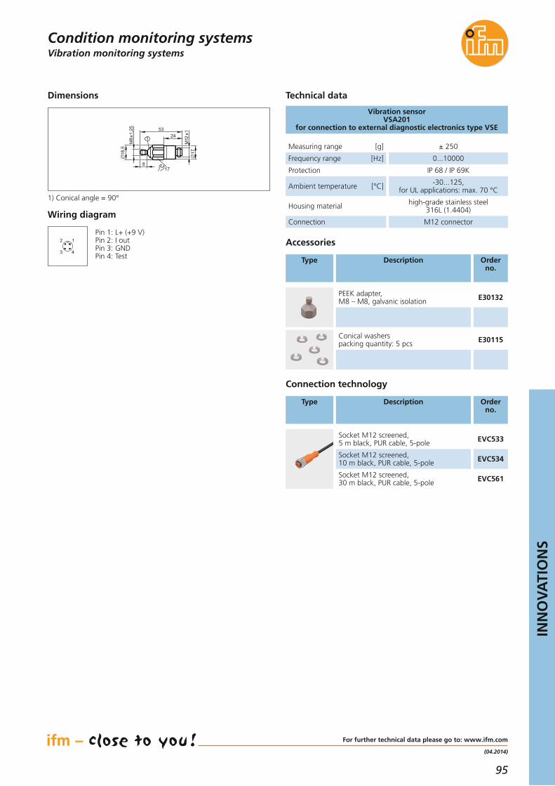
95
INN
OV
ATI
ON
S
(04.2014)
Vibration monitoring systems
Technical data
Measuring range [g] ± 250
Frequency range [Hz] 0...10000
Protection IP 68 / IP 69K
Ambient temperature [°C] -30...125, for UL applications: max. 70 °C
Housing material high-grade stainless steel 316L (1.4404)
Connection M12 connector
Vibration sensor VSA201
for connection to external diagnostic electronics type VSE
Dimensions
18,5
M8x
1,25
M12
x117
5324
178
1
Accessories
Type Description Order no.
PEEK adapter, M8 – M8, galvanic isolation E30132
1) Conical angle = 90°
Connection technology
Type Description Order no.
Socket M12 screened,5 m black, PUR cable, 5-pole EVC533
Socket M12 screened,10 m black, PUR cable, 5-pole EVC534
Socket M12 screened,30 m black, PUR cable, 5-pole EVC561
Wiring diagram
43
2 1Pin 1: L+ (+9 V)Pin 2: I outPin 3: GNDPin 4: Test
Condition monitoring systems
Conical washerspacking quantity: 5 pcs E30115
For further technical data please go to: www.ifm.com

96
Automation of mobile vehicles – easy, modular, cost-optimised
ecomatmobile BasicIn many small and compact mobile applications, the requirements on control tasks are increasing. Cost-optimised and modular mini controllers for mobile usesuch as ecomatmobile Basic consist of three components BasicRelais, BasicController as well as BasicDisplay which are well adapted to each other.The BasicController range is now enhanced with theaddition of the new BasicController plus. In addition tothe outputs rated for controlling proportional hydraulicfunctions, two H-bridges and the corresponding soft-ware functions, e.g. for the reversal of the direction ofrotation of electric motors, have been integrated. Multifunctional inputs which can be configured via theapplication software complete the new control module.
High-performance current-controlled outputs with H-bridge function
Connection of sensors and actuators without additional external wiring
High-performance CAN interfaces for various communication tasks
Easy installation thanks to the coordinatedmechanical concept by ecomatmobile Basic
Programmable to IEC 61131-3 with CoDeSys
More power in mobile machines
Systems for mobile machines

97
INN
OV
ATI
ON
S
(11.2014)
Mobile controllers
Functions and advantagesThe compact, flexible and inexpensive mini controllerreplaces the conventional relay logic and also demanding and complex process controllers.
• Mechanical designThe control electronics integrated in a compact plastic housing provide all the necessary connections for theinputs and outputs, communication and programming. The coded connectors for mobile use are easy to handle and available all over the world. The connection ofsensors and actuators is carried out without furtherexternal wiring. Due to an increase of the protection rating through a cover and a pluggable cable seal the BasicControllercan also be used in areas that are exposed to splash-ing water.
• Powerful electronicsThe integrated 32-bit processor and the electronicsare optimally tailored to the application. Inputs andoutputs can be configured to the application via theuser program.Powerful outputs allow controlling ofproportional hydraulic valves. H-bridge functions, e.g. for the reversal of the direction of rotation, allowuse also for electric motors. A status LED indicatesthe current operating status of the module.
• Programmable to IEC 61131-3The CoDeSys software enables a clear and easy creation of the application software for the user. Thecontrol module BasicController supports all commonCoDeSys programming languages. Simple and clearly structured function libraries are available forcommunication and special device functions.
• Communication interfacesThe BasicController is equipped with two CAN inter-faces to ISO 11898. These interfaces are used to ex-change data with the connected BasicDisplay, furtherBasicController modules or the engine controller.Among others, the interfaces support the CANopenprotocol and the J1939 protocol. The CAN interfaces are also used for programming.To do so, the unit electronics are directly and conveniently activated via the powerful PC-CAN inter-face CANfox. In this way, operating system and appli-cation programme can be loaded or parameterschanged.
Applications:compact construction machines, attachments, mini vehicles
Inputs (total):digital, analogue, frequencydigital, resistance measurement
844
Outputs (total):digital, PWM, current-controlled, 2.5 Adigital, PWM, current-controlled , H bridge, 4 A
84
4
Data memory SRAM [kB] 592
Data memory Flash [kB] 1536
Data memory (retain), FRAM [kB] 1
For further technical details please visit: www.ifm.com
Systems for mobile machines
Description Orderno.
BasicController plus 8 I / 8 O CR0411
Common technical data
BasicController plus
The products
Cover plastic, potted
Device connection AMP blade male terminals 6.3 mm
Protection rating,with cover EC0401, EC0402
IP 20IP 54
Operating voltage [V DC] 8...32
Current consumption [mA] ≤ 45 (at 24 V DC)
Temperature range [°C] -40...85
Indicators LED red / green
Processor PowerPC, 50 MHz
Supported CAN protocols
CANopen(DS 301 V4.1)
SAE J 1939free CAN protocol
Standards and tests(extract)
CE,E1 (UN-ECE R10)
BasicController 12 I / 8 O CR0401
BasicController 12 I / 12 O CR0403
Starter set consisting of BasicController, BasicRelais, BasicDisplay incl. software, power supply, cable and accessories
EC0400
Cover IP 54 without display recess, with cable seal EC0401
Cover IP 54 with built-in display recess and cable seal EC0402
Connection cable for 2 BasicControllers EC0451
Plug set for BasicController EC0456
CAN programming interface CANfox EC2112
Adapter set CAN/RS232 for CANfox EC2113
Programming software CODESYS, German V2.3 CP9006
Programming software CODESYS, English V2.3 CP9008
Programming software CODESYS V 2.3
BasicRelais CR0421

98
SmartController XL with 64 multifunctional inputs and outputs
SmartController for mobile machinesifm electronic has launched the SmartController XL inresponse to market demand for a low-cost compactcontroller for mobile applications. Offering 64 inputsand outputs, it can be used as a main controller forsmall machines or in applications for processing of analogue and digital sensor and actuator signals. The SmartController XL was developed particularly foruse in off-highway and mobile machines on the basisof the current standards and long-term experience.
Flexible networkingNetworking of the modules with the CANopen protocolon the powerful CAN bus allows quick implementationof the application. Three integrated CANopen inter-faces serve for the flexible and powerful extension ofthe system with further I/O or control modules. Also,the exchange of SAE J 1939 engine data is easy to carryout via these interfaces.
Analogue and digital I/O with diagnosticfunction for mobile applications
For complex control functions in mobilemachines
3 CAN interfaces with CANopen and SAE J 1939 protocol
Freely programmable with CODESYS 2.3 to IEC 61131-3
E1 type approval of the Kraftfahrtbundes-amt (German Federal Motor Transport Authority)
Many inputs and outputs for little money
Systems for mobile machines

99
INN
OV
ATI
ON
S
(04.2014)
For further technical details please visit: www.ifm.com
Mobile controllers
Description Order no.
SmartController XL, 32 bits, 16 I / 16 O CR2532
Technical data
SmartController XLCR2532
Products
Housing closed metal housing with flange fastening
Device connectionAMP connector
55 poles latched, protectedagainst reverse polarity
Protection IP 67
Operating voltage [V DC] 8...32
Functions and advantages
• Mechanical designThe two-part control electronics integrated into acompact metal housing provides all necessary connections for the inputs and outputs, communica-tion and programming via the reverse-polarity protec-ted central plugs suitable for mobile applications.
• Powerful electronicsThe integrated 32-bit processor and the electronicsare optimised for mobile applications. The inputs andoutputs distributed over two device units can be ad-apted to the application via the user program. Thetwo-colour status LED displays the most importantsystem messages.
• Configurable inputs / outputsThe inputs / outputs can be freely configured by theuser. Digital inputs, analogue inputs for current orvoltage, inputs with diagnostic capability and fastpulse inputs are available. The outputs can be set asdigital outputs, PWM and current-controlled outputs.
• Programming to IEC 61131-3 with CODESYSThe CODESYS software enables clear and easy creation of the application software for the user. TheSmartController XL supports all common CODESYSprogramming languages. Simple and clearly structuredfunction libraries are available for communication andspecial device functions.
• CAN-interfaces with CANopen protocolThe SmartController XL is equipped with three CAN interfaces to ISO 11898. Using these, data canfor example be exchanged with the connected display, further I/O modules or an engine controller.The interfaces support, among other things, the CANopen and the J 1939 protocol.The CAN interfaces are also used for programming.To do so, the device electronics are directly and conveniently activated via the powerful PC interfaceCANfox. This enables users to load the operating system and the application program or to change parameters. The basic unit of the controller is linked directly to theintegrated, pre-configured I/O extension via a CANconnection.
Applications:• Compact construction machines• Agricultural machines• Municipal vehicles
Current consumption [mA] ≤ 100
Temperature range [°C] -40...85
Indicators LED red / green
Controller Freescale PowerPC
Supported CAN protocolsCANopen
(CiA DS 301 V4),SAE J 1939
Standards and tests(extract)
CE,E1 (UN-ECE R10)
EN50155 / EC50121
Systems for mobile machines
Connector, 55 poles (wirable) EC2013
Cable with connector 55 poles, 1.2 m EC2086
Programming cable with USB adapter, 2 m EC2096
Programming software CODESYS, German V2.3 CP9006
Programming software CODESYS, English V2.3 CP9008
Program memory [kB] 1536
Data memory RAM [kB] 592
Data memory non-volatile [kB] 2
Programming software CODESYS V 2.3
Interfaces 3 x CAN
Number of inputs(configurable)Digital (positive / negative sensor signals),Diagnosis, analogue (0...10 / 32 V, 0...20 mA, ratiometric)Digital (positive sensor signals), diagnosisResistance measurement (16 Ω...30 kΩ)Digital (positive sensor signals)Frequency (≤ 30 kHz)Digital (positive sensor signals)
32
8
4
8
12
Number of outputs(configurable)Digital, positive-switching,PWM output (2 A)Digital, positive-switching, PWM output (2 A)Current-controlled (2 A)Digital, positive-switching, PWM output (4 A) (alternative 2x analogue output 0...10 V)Digital, positive-switching (2 A)
32
16
4
8
8

100
Visualisation for mobile machines – easy and cost-optimised
ecomatmobile BasicIn many small and compact mobile applications, the requirements on control tasks are increasing. The cost-optimised and modular mini controller ecomatmobilesolves these tasks.The BasicDisplay XL complements the existing compo-nents BasicRelay, BasicController and BasicDisplay.Thanks to its electrical and mechanical features it canoptimally be integrated in the existing ecomatmobileBasic family.Free programming and the easy set-up of the visualisa-tion screens with CODESYS to IEC 61131-3 ensure independent operation in different applications.
Easy installation thanks to a coordinatedmechanical concept
Indication of system messages and visualisation of machine functions
High-performance CAN interface for various communication tasks
Programmable to IEC 61131-3 with CODESYS
E1 type approval of the Kraftfahrtbundes-amt (German Federal Motor TransportAuthority)
Looking for a bigger size? ecomatmobile BasicDisplay XL
Systems for mobile machines

101
INN
OV
ATI
ON
S
(04.2014)
Dialogue modules / displays
Description Orderno.
BasicDisplay XL, 4.3“, 480 x 272 pixels CR0452
Mounting plate for panel mounting BasicDisplay XL EC0404
Mounting support for surface mounting (RAMmount) EC0406
Connection cable BasicDisplay XL, 5 m – BasicController with CAN terminating resistors
EC0454
Connection cables BasicDisplay XL, 5 m – 2 BasicControllers, 50 cm with CAN terminating resistors
EC0455
Programming software CODESYS, German version CP9006
Programming software CODESYS, English version CP9008
CAN programming interface CANfox EC2112
Adapter set CAN/RS232 for CANfox EC2113
Technical data
BasicDisplay XLCR0452
The products
Housing Plastic with M52 screwconnection
Device connection M12 connector
Protection FrontBack
IP 67IP 65
Operating voltage [V DC] 8...32
Functions and advantagesThe high-resolution colour display replaces conventional analogue displays and, in part, the rudimentary operating elements of machines.
• High-resolution displayProtected by a continuous membrane, the modern display, which can even be read in sunlight, providesa resolution of 480 x 272 pixels with an aspect ratioof 16:9. Graphics can be shown with a colour depthof up to 256 colours.
• Mechanical designThe BasicDisplay XL has a sealed plastic housing withprotection rating IP 67. The integrated M12 connector provides all important connections for supply andcommunication. The display can be mounted directlyon the operator panel using a centralised fixing nutor it can be snapped into the mounting support.
• Powerful electronicsThe integrated 32-bit processor and the electronicstailored to the applications are optimally adapted tothe application area. A status LED indicates the current operating status of the display. Thanks to the integrated watchdog, stand-alone operation of the BasicDisplay XL is possible.
• Programming according to IEC 61131-3The CODESYS software enables clear and easy creation of the application software for the user. Function libraries are available for the special functions of theBasicDisplay XL. The graphic elements are createdand animated via the integrated visualisation.
• Communication interfacesThe BasicDisplay XL is fitted with a CAN interface toISO 11898. These interfaces are for example used toexchange data between the connected controller, thedecentralised input/output modules or the enginecontroller. To perform these tasks the interface supports the CANopen and the J1939 protocol. With the masterfunctionality of the CANopen protocol, networks canbe built via decentralised input /output modules.
Applications:Mobile construction equipment and building material machines, compact municipal vehicles,machines and equipment for market gardeningand landscape gardening.
Current consumption [mA] ≤ 100
Temperature range Operation [°C]Storage [°C]
-20...65-30...80
4.3“ TFT LCD display 480 x 272256 colours
Processor PowerPC50 MHz
Indication LED (red/green)
Data memory SRAM [kB] 592
Program / data memory Flash [kB] 1536
Data memory (retain) [kB] 1
Function keys with softkey function,backlit 6
Navigation key with cursor function,backlit 1
Interfaces 1 x CAN
Supported CAN protocols CANopen (DS 301 V4.1)SAE J 1939
Programming software CODESYS V2.3
Standards and tests(extract)
CE, E1 (UN-ECE R10)
For further technical details please visit: www.ifm.com
Systems for mobile machines

102
*Some offered information is available country-specific.
www.ifm.comInformation around the clock andaround the globe in 23 languages on the internet.
• Information- product innovations- company news- exhibition info- locations- jobs
• Documentation- data sheets- operating instructions- manuals- approvals- CAD data
• Communication*- request for documents- recall service- live advice- newsletter
• Selection- interactive product selection aids- configuration tools- data sheet direct
• Animation- virtual product animations- flash movies (video sequences)
• Application- applications- product recommendations- calculation aids
• Transaction*- e-shop processing- e-procurement catalogues

103
Convenient order processingvia the e-shop** on the internet.
Secured authentication
Customer-related priceindication
Real time availability check
Personal product favourites
Online parcel tracking
Individual order history
Convenient quick input form
Simple order processing
Management of shippingaddresses
Confirmations by e-mail
**Already available in many countries.

Position sensors
Sensors formotion control
Industrial imaging
Safety technology
Process sensors
Condition monitoringsystems
Industrialcommunication
Identification systems
Systems formobile machines
Connectiontechnology
Overviewifm product range:
Accessories
ifm a
rtic
le n
o. 7
8001
251
· We
rese
rve
the
right
to
mak
e te
chni
cal a
ltera
tions
with
out
prio
r no
tice.
· Pr
inte
d in
Ger
man
y on
non
-chl
orin
e bl
each
ed p
aper
. 11/
14
Cert no. IMO-COC-027827
Visit our website:
www.ifm.com
ifm electronic gmbhFriedrichstraße 145128 EssenTel. +49 / 201 / 24 22-0Fax +49 / 201 / 24 22-1200E-mail [email protected]
Over 70 locations worldwide –at a glance at www.ifm.com