
INNOVATION Product Solutions - obs.schall-messen.de · INNOVATION Product Solutions. 2 Taylor...
40
INNOVATION Product Solutions
Transcript of INNOVATION Product Solutions - obs.schall-messen.de · INNOVATION Product Solutions. 2 Taylor...

INNOVATIONProduct Solutions

2
Taylor Hobson – the experts in automotive, bearings and optics metrology
Established in 1886, Taylor Hobson is the world leader in surface and form metrology and developed the first roundness and surface finish measuring instruments.
Taylor Hobson is part of the Ultra Precision Technologies Division of AMETEK, Inc. which is a leading global manufacturer of electronic instruments and electromechanical devices with 2015 sales of $4 billion. AMETEK has over 15,000 colleagues at more than 120 manufacturing locations around the world. Supporting those operations are more than 100 sales and service locations across the United States and in 30 other countries around the world.
We provide contact and non-contact measurement solutions for the most demanding applications on a global basis, with a worldwide infrastructure to support our clients; we are a truly global ultra precision metrology company.
We are pioneers, continually developing our products to meet the ever-increasing demands of next generation technologies, particularly in optics, bearings, automotive, aerospace, medical and renewable energy technologies.
This forward thinking philosophy is captured perfectly in our diverse range of product solutions. Recent developments include new optics measurement systems and a full suite of dedicated software analysis packages.
Manufactured components require exceptional levels of quality, durability, precision and reliability in order to meet the demanding requirements of modern applications. Recent developments by Taylor Hobson deliver an in depth understanding of characteristics such as surface finish, contour, form, radius, roundness and harmonic analysis, providing vital feedback for improvements in design and production.
Advanced metrology
Fluid dynamic bearing, 3D high data density measurement
Talyrond® 500H Series
Helix angle correction and thread analysis
Form Talysurf® PGI
Measure form, roughness, waviness and radius in one
Form Talysurf® i-Series
Comprehensive surface finish analysis
Surtronic® range
3
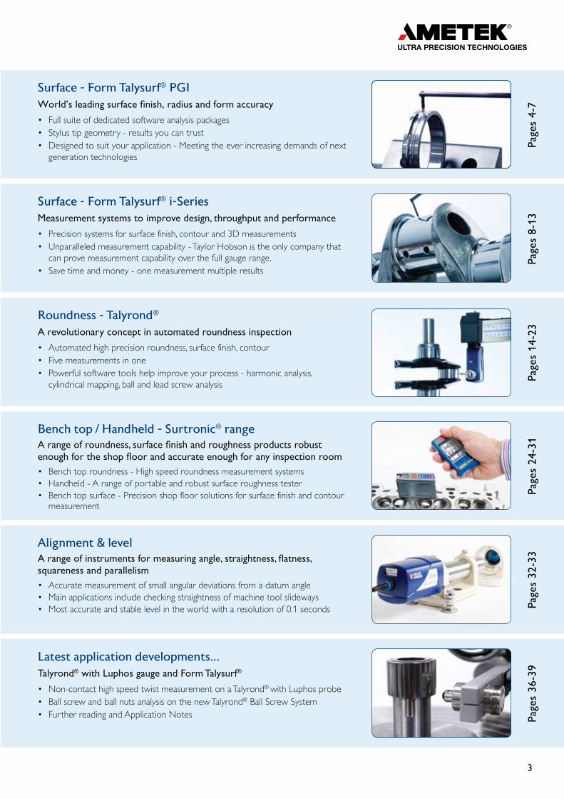
Surface - Form Talysurf® PGIWorld’s leading surface finish, radius and form accuracy
• Full suite of dedicated software analysis packages• Stylus tip geometry - results you can trust• Designed to suit your application - Meeting the ever increasing demands of next
generation technologies
Page
s 4-
7
Surface - Form Talysurf® i-Series Measurement systems to improve design, throughput and performance
• Precision systems for surface finish, contour and 3D measurements• Unparalleled measurement capability - Taylor Hobson is the only company that
can prove measurement capability over the full gauge range. • Save time and money - one measurement multiple results
Page
s 8-
13
Roundness - Talyrond®
A revolutionary concept in automated roundness inspection
• Automated high precision roundness, surface finish, contour• Five measurements in one• Powerful software tools help improve your process - harmonic analysis,
cylindrical mapping, ball and lead screw analysis
Page
s 14
-23
Bench top / Handheld - Surtronic® rangeA range of roundness, surface finish and roughness products robust enough for the shop floor and accurate enough for any inspection room • Bench top roundness - High speed roundness measurement systems• Handheld - A range of portable and robust surface roughness tester• Bench top surface - Precision shop floor solutions for surface finish and contour
measurement
Page
s 24
-31
Alignment & levelA range of instruments for measuring angle, straightness, flatness, squareness and parallelism • Accurate measurement of small angular deviations from a datum angle• Main applications include checking straightness of machine tool slideways• Most accurate and stable level in the world with a resolution of 0.1 seconds Pa
ges
32-3
3
Latest application developments...Talyrond® with Luphos gauge and Form Talysurf®
• Non-contact high speed twist measurement on a Talyrond® with Luphos probe• Ball screw and ball nuts analysis on the new Talyrond® Ball Screw System• Further reading and Application Notes Pa
ges
36-3
9
4
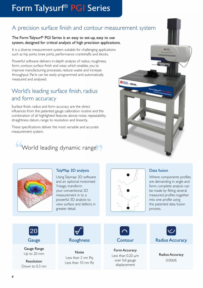
The Form Talysurf® PGI Series is an easy to set-up, easy to use system, designed for critical analysis of high precision applications.
It is a diverse measurement system suitable for challenging applications such as hip joints, knee joints, performance crankshafts and blocks.
Powerful software delivers in-depth analysis of radius, roughness, form, contour, surface finish and wear, which enables you to improve manufacturing processes, reduce waste and increase throughput. Parts can be easily programmed and automatically measured and analysed.
Gauge
Gauge RangeUp to 20 mm
ResolutionDown to 0.3 nm
Roughness
Noise
Less than 2 nm RqLess than 10 nm Rz
Contour
Form Accuracy
Less than 0.20 µm over full gauge displacement
Radius Accuracy
Radius Accuracy
0.006%
World’s leading surface finish, radius and form accuracySurface finish, radius and form accuracy are the direct influences from the patented gauge calibration routine and the combination of all highlighted features above; noise, repeatability, straightness datum, range to resolution and linearity.
These specifications deliver the most versatile and accurate measurement system.
TalyMap 3D analysis
Using Talymap 3D software and an optional motorised Y-stage, transform your conventional 2D measurement in to a powerful 3D analysis to view surface and defects in greater detail.
Data fusion
Where components profiles are demanding in angle and form, complete analysis can be made by fitting several measured profiles together into one profile using the patented data fusion process.
1
2
3
‘‘‘‘
World leading dynamic range
Form Talysurf® PGI Series
A precision surface finish and contour measurement system

5
Aerospace
The Form Talysurf® PGI Series is used in conjunction with Q-Link (production interface) where data and strict standard operating procedure control is mandatory.
Analysis capability includes form, contour and DXF comparison.
Research and development
The ideal instrument for a wide range of measurements and challenging applications in university and research laboratories.
Analysis capability includes radius, roughness, form, contour, surface finish and wear.
Analysis capability includes radius, roughness, form and wear.
MedicalUnderstanding implant characteristics such as wear to provide vital feedback for design improvements.
Automotive
Control of the manufacturing process through the analysis of defects and scratches.
Analysis capability includes contour, Rk, R & W and wear.
Designed to suit your applicationMeeting the ever increasing demands of next generation technologies

6
Gauge
Gauge RangeUp to 20 mm
ResolutionDown to 0.3 nm
Roughness
Noise
Less than 2 nm RqLess than 10 nm Rz
Contour
Form Accuracy
Less than 0.20 µm over full gauge displacement
Radius Accuracy
Radius Accuracy
0.006%
A dedicated bearing measurement systemThe Form Talysurf® PGI Bearings has been designed for critical analysis of high precision bearings.
Bearings require exceptional levels of quality, durability, precision and reliability in order to meet the demanding requirements of modern applications.
Taylor Hobson products deliver an in depth understanding of bearing characteristics such as radius, form, surface finish, contour and dominant wavelength, providing vital feedback for improvements in design and production.
Buy with confidence - results everyone trustsRadius and form accuracy are the direct influences from the patented gauge calibration routine and the combination of the instrument’s noise, repeatability, straightness datum, range to resolution and linearity. These specifications deliver the market-leading bearing measurement system.
‘‘‘‘
World leading radius and form accuracy
Nominal Ball Diameter
Gothic Arch Parameters
Al Ar
Bearing RaceZr Zl
Xr Xl
Rl Rr
Hc
X = Offset (Horiz)Z = Offset (Vert)R = RadiusA = Vertex AngleHc = Clearance
l = Left Arc r = Right Arc
Gothic Arch AnalysisAllows manufacturers to predict how a bearing is going to function based on where the ball sits within the bearing race.
• Contact angle• Radius• Offset and more
Form Talysurf® PGI Bearings

7
DFX Creator
A utility that allows creation of DXF data, enabling comparison of design profile to part profile.
• Logarithmic equation• Free form equations• Tolerance zones
TalyMap Contour
Allows alignment of measured profiles to design data as well as automated dimensioning.
• Tolerance zones• Error deviation• x-offset calculation
Helix Angle Correction
Compensate for the helix angle enabling profile measurement in line with the component axis.
LS Arc Auto
Non operator influenced analysis of spherical raceway by use of an automated routine. This simple algorithm will work regardless of part position or size.
α
Morphological Filtering
Measure roughness using a diamond stylus and simulate form measurement using a ball stylus - one measurement two results saving time.
Full suite of dedicated software analysis packagesTaylor Hobson has a long history with the bearings industry, this association has helped to evolve powerful software solutions to suit your applications

8
A high range, high resolution system for contour and surface finish measurement
Gauge
Gauge RangeUp to 5 mm
ResolutionDown to 0.4 nm
Roughness
Noise
Less than 6 nm Rq
Contour
LS Arc Measurement Less than 3.3 µm
Pt Less than 0.25 µm
Temperature
Temperature compensation
ensures consistent system performance
‘‘‘‘Revolutionary
gauge technology
Ideally suited for cylinder heads and blocks, gears, sheet metal and many other applications.
Surface and contour in oneThe Form Talysurf® i-Series is a high accuracy instrument range capable of simultaneous surface finish and contour measurement. The system’s low noise axes and high resolution gauge ensures measurement integrity with choice of gauge ranges providing versatility for a variety of applications.
Temperature compensationStandard across all i-Series models, this unique system monitors and feeds back changes in ambient temperature, ensuring consistent system performance and high measurement integrity, regardless of environmental effects.
Tailored to suit your applicationConfigurable platform to suit your measurement requirements and budget.
Gauge range 1 mm 2 mm 5 mm
Traverse length 60 mm 120 mm 200 mm
Column height 450 mm 700 mm 1000 mm
Base 760 mm x 500 mm 1200 mm x 900 mm
Form Talysurf® i-Series

9
Surface analysis• Form
• Radius
• Roughness
• Waviness
• Dominant wavelength
Contour analysis
• Radius
• Angle
• Height
• Length
• Distance and more
Save time and money - one measurement multiple resultsKey measurements for design and production
3D
Using an optional motorised Y-stage and Talymap, transform your conventional 2D measurement in to a 3D analysis tool.
Unparalleled measurement capabilityTaylor Hobson is the only company that can prove measurement capability over the full gauge range. Taylor Hobson quote world leading specification capabilities over the full gauge range. Other manufacturers quote less radius accuracy and form capability over a significantly reduced gauge range, indicating less confidence in their measurement results.
10
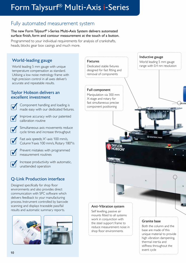
Inductive gaugeWorld leading 5 mm gauge range with 0.4 nm resolution
FixturesDedicated stable fixtures designed for fast fitting and removal of components
Full componentManipulation via 300 mm X-stage and rotary for fast simultaneous precise component positioning
Granite baseBoth the column and the base are made of this unique material to provide high vibration dampening, thermal inertia and stiffness throughout the event cycle
10
World-leading gauge World leading 5 mm gauge with unique temperature compensation as standard. Utilising a low noise metrology frame with high precision control in all axes deliver’s accurate and repeatable results.
Anti-Vibration systemSelf levelling, passive air mounts fitted to all systems work in conjunction with the steel support frame to reduce measurement noise in shop floor environments
✓
Taylor Hobson delivers an excellent investment
Component handling and loading is made easy with our dedicated fixtures.
✓
✓
✓
✓
✓
Improve accuracy with our patented calibration routine
Simultaneous axis movements reduce cycle times and increase throughput
Fast axis speeds; X1-axis 100 mm/s, Column Y-axis 100 mm/s, Rotary 180°/s
Increase productivity with automatic, unattended operation
Prevent mistakes with programmed measurement routines
Q-Link Production interface Designed specifically for shop floor environments and also provides direct communication with SPC software which delivers feedback to your manufacturing process. Instrument controlled by barcode scanning and displays traceable pass/fail results and automatic summary reports.
Form Talysurf® Multi-Axis i-Series
Fully automated measurement systemThe new Form Talysurf® i-Series Multi-Axis System delivers automated surface finish, form and contour measurement at the touch of a button.
Programmed to your individual requirements for analysis of crankshafts, heads, blocks gear box casings and much more.

11‘‘
‘‘Ultra softwarePowerful analysis software for all parameters and run by our production interface automates control and reporting
Traverse unit200 mm traverse straightness unit
Support steel frameWelded steel frame for rigid support of granite instrument base and motorised column; includes heavy duty leveling mechanism on all four legs
700 mm columnAutomatically moved on motorised Y-axis stage over 700 mm
ECUIndustrial electrical and PC cabinet
UKAS calibration and testingA quick and simple automated routine enabling gauge calibration over the full range. This unique calibration delivers world leading surface and form accuracy.
Taylor Hobson provides full certification for artefacts and instruments in our purpose built ISO graded clean room UKAS facility. Our UKAS laboratory is able to measure all of the parameters associated with surface texture, including French, German, USA and Japanese derivatives.
Applications
• Gear box casings
• Cylinder heads
• Cylinder blocks
• Crankshafts
11
0026 2624
Programmed to your individual requirements

12
Gauge calibrationThe Talysurf i-Series uses a fast and simple process to calibrate the gain of the system. Utilizing a traceable step height standard calibrated to international standards, the automated routine calibrates the system without operator influence or manual intervention.
Form optimisationThe Talysurf i-Series uses a polynomial and spline form optimisation to remove the surface shape. This quick and simple technique allows roughness and waviness to be analysed over flat and curved surfaces.
Surface Noise - Less than 8 nm Rq
The Talysurf i-Series is a simple to operate high accuracy instrument capable of roughness and waviness measurement. The systems low noise axes and high resolution gauge ensures measurement integrity.
Versatile and easy to use...Utilizing powerful control and analysis software the measurement of roughness and waviness has never been easier.
GaugeGauge Range - 1000 µm
Resolution - Down to 0.16 nm
Talysurf® i-Series
An affordable, low noise, high resolution system for roughness and waviness measurement

13
Contour measurement
The Form Talysurf® WRi (Wide Range Inductive) provides an in depth understanding of the measurement of contour. Taylor Hobson's unique ball calibration routine delivers unrivalled gauge linearity and therefore form measurement capability.
Easy operationSimply position the component so that all features to be measured are within gauge range. As the system moves over the features the integrity of the data is assured because of the linearity over the entire range has been considered in the calibration process. TalyMap Contour software handles the manipulation and analysis of the data quickly and easily.
A high range versatile system dedicated for contour measurement
Full dimensional analysis, including deviation errors and tolerances✓
✓
13
TalyMap Contour
✓
✓
✓
Easy to learn, icon based user interface
Automatically analyse features with large positional tolerances
DXF data comparison
Rapid desktop report generation
✓ Full metrology traceability
Form Talysurf® WRi
14
Roughness
NoiseLess than 30 nm Rq all axes
Ra valuesLess than 0.1 µm
Contour
LS Arc measurement5 µm
Pt0.5 µm
Gauge
Gauge RangeUp to 4 mm
ResolutionDown to 0.3 nm
Roundness
Radial Accuracy
± 0.01 µm
Monitoring manufacturing
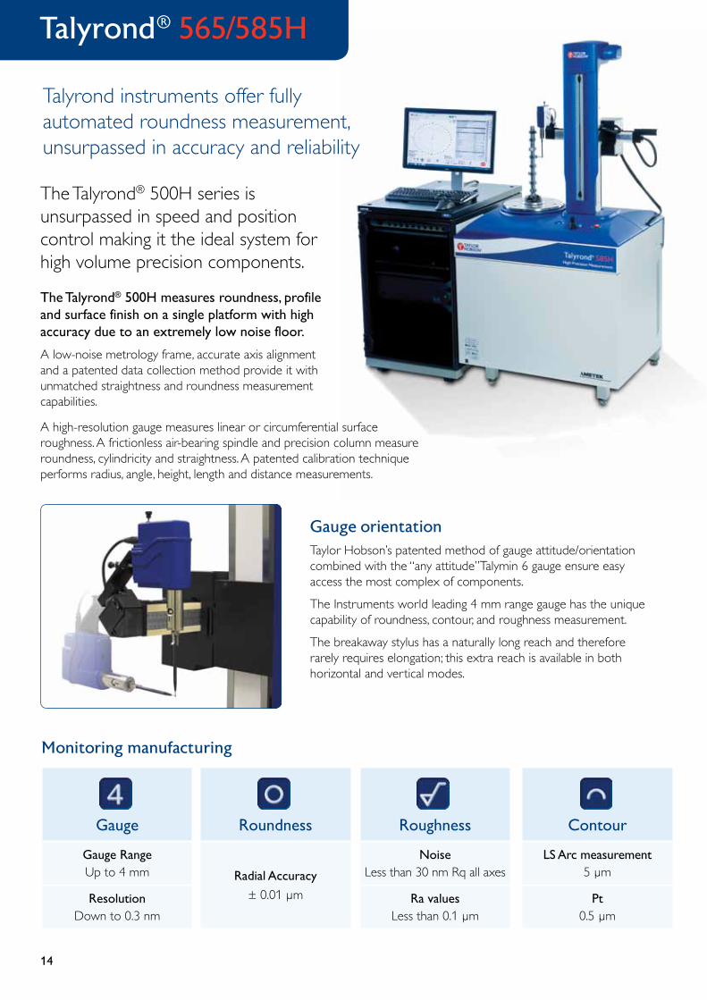
Talyrond® 565/585H
Talyrond instruments offer fully automated roundness measurement, unsurpassed in accuracy and reliability
The Talyrond® 500H series is unsurpassed in speed and position control making it the ideal system for high volume precision components.
The Talyrond® 500H measures roundness, profile and surface finish on a single platform with high accuracy due to an extremely low noise floor.
A low-noise metrology frame, accurate axis alignment and a patented data collection method provide it with unmatched straightness and roundness measurement capabilities.
A high-resolution gauge measures linear or circumferential surface roughness. A frictionless air-bearing spindle and precision column measure roundness, cylindricity and straightness. A patented calibration technique performs radius, angle, height, length and distance measurements.
Gauge orientationTaylor Hobson’s patented method of gauge attitude/orientation combined with the “any attitude”Talymin 6 gauge ensure easy access the most complex of components.
The Instruments world leading 4 mm range gauge has the unique capability of roundness, contour, and roughness measurement.
The breakaway stylus has a naturally long reach and therefore rarely requires elongation; this extra reach is available in both horizontal and vertical modes.
15
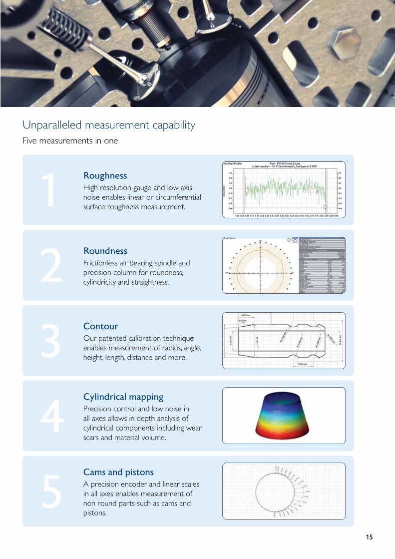
Unparalleled measurement capabilityFive measurements in one
RoughnessHigh resolution gauge and low axis noise enables linear or circumferential surface roughness measurement.1RoundnessFrictionless air bearing spindle and precision column for roundness, cylindricity and straightness.2ContourOur patented calibration technique enables measurement of radius, angle, height, length, distance and more.3Cylindrical mappingPrecision control and low noise in all axes allows in depth analysis of cylindrical components including wear scars and material volume.
4Cams and pistonsA precision encoder and linear scales in all axes enables measurement of non round parts such as cams and pistons.
5

16
Roughness
NoiseLess than 20 nm Rq all axes
Ra valuesLess than 0.05 µm
Contour
LS Arc measurement5 µm
Pt0.5 µm
Gauge
Gauge RangeUp to 4 mm
ResolutionDown to 0.3 nm
Roundness
Radial Accuracy
± 0.008 µm
Monitoring manufacturing
Talyrond® 595H
Ultra high precision roundness measurement
Measure three critical performance elements roundness, surface finish, and now contour exactly as they were produced.
The Talyrond® is ideally suited for the high-accuracy measurement of applications such as precision bearings, fuel injectors, crankshafts and turbocharger parts.
Numerous specialised accessories allow the instrument to accommodate the industry’s most demanding applications.
The active anti-vibration mounts protect the system from external vibration by use of piezo actuated mounts.
3D cylindrical mapping
For production issues beyond the scope of traditional 2D inspection techniques.
Advanced cone analysis
3D topography of a wear scar
With high accuracy and high resolution in all axes, Talyrond® 595H allows you to measure in 3 dimensions for more thorough examination of flaws, defects and cutting tool geometry effects that influence performance or lead to component malfunction.
•Twistorleaddetection •Machiningdefects
•Wearscaranalysis •Leakdetectionandmore
‘‘‘‘
World-beating noise floor
17
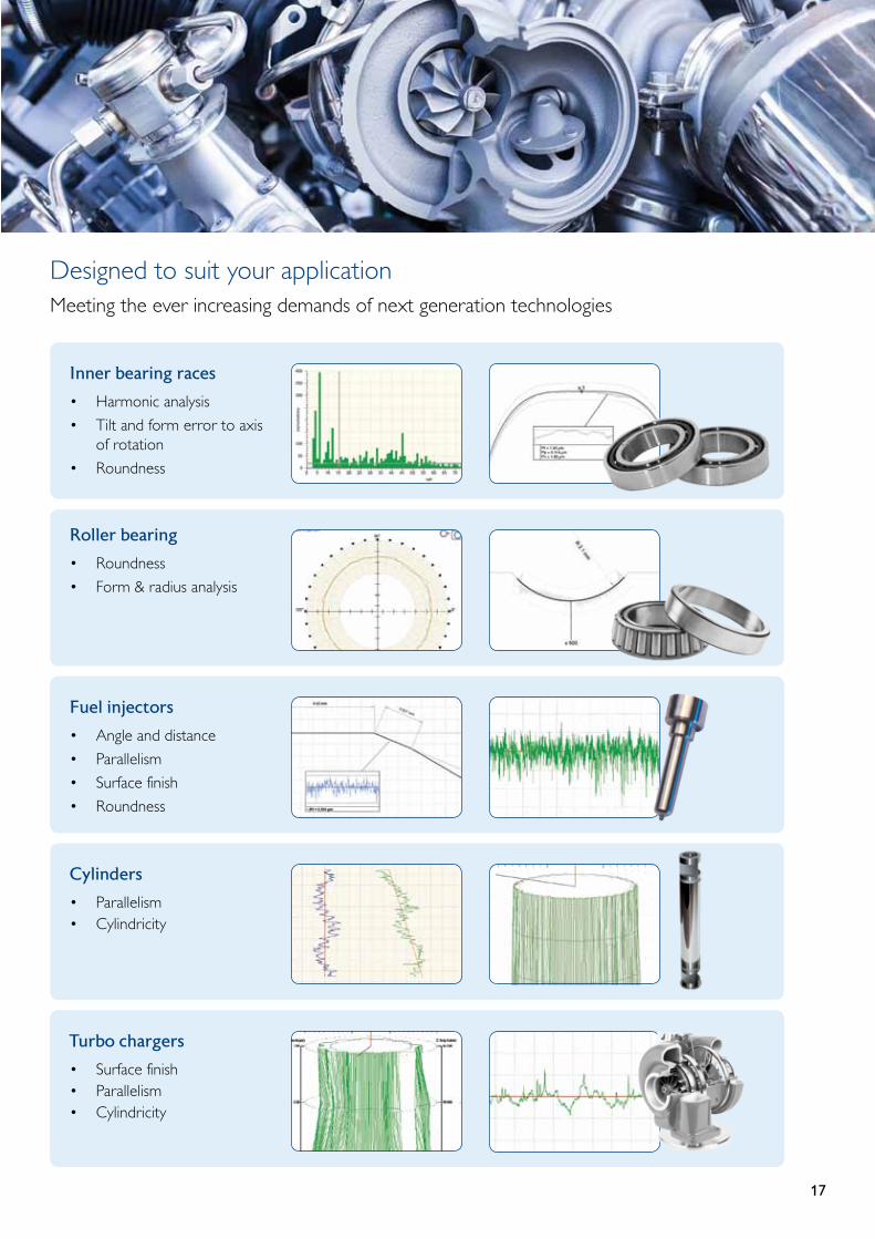
Designed to suit your applicationMeeting the ever increasing demands of next generation technologies
Inner bearing races
• Harmonic analysis
• Tilt and form error to axis of rotation
• Roundness
Roller bearing
• Roundness
• Form & radius analysis
Fuel injectors
• Angle and distance
• Parallelism
• Surface finish
• Roundness
Cylinders
• Parallelism• Cylindricity
Turbo chargers
• Surface finish• Parallelism• Cylindricity
18
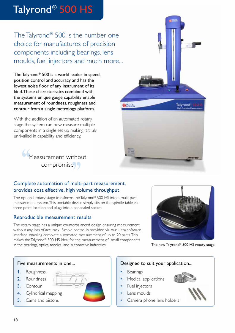
Complete automation of multi-part measurement, provides cost effective, high volume throughputThe optional rotary stage transforms the Talyrond® 500 HS into a multi-part measurement system. This portable device simply sits on the spindle table via three point location and plugs into a concealed socket.
Reproducible measurement resultsThe rotary stage has a unique counterbalanced design ensuring measurement without any loss of accuracy. Simple control is provided via our Ultra software interface, enabling complete automated measurement of up to 20 parts. This makes the Talyrond® 500 HS ideal for the measurement of small components in the bearings, optics, medical and automotive industries.
The Talyrond® 500 is the number one choice for manufactures of precision components including bearings, lens moulds, fuel injectors and much more...
The Talyrond® 500 is a world leader in speed, position control and accuracy and has the lowest noise floor of any instrument of its kind. These characteristics combined with the systems unique gauge capability enable measurement of roundness, roughness and contour from a single metrology platform.
With the addition of an automated rotary stage the system can now measure multiple components in a single set up making it truly unrivalled in capability and efficiency.‘‘‘‘Measurement without
compromise
The new Talyrond® 500 HS rotary stage
Talyrond® 500 HS
1. Roughness
2. Roundness
3. Contour
4. Cylindrical mapping
5. Cams and pistons
Five measurements in one...
• Bearings
• Medical applications
• Fuel injectors
• Lens moulds
• Camera phone lens holders
Designed to suit your application...
19
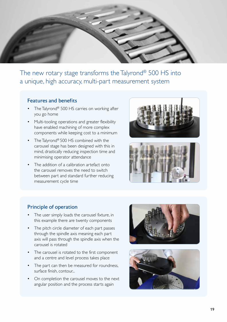
Principle of operation
• The user simply loads the carousel fixture, in this example there are twenty components
• The pitch circle diameter of each part passes through the spindle axis meaning each part axis will pass through the spindle axis when the carousel is rotated
• The carousel is rotated to the first component and a centre and level process takes place
• The part can then be measured for roundness, surface finish, contour...
• On completion the carousel moves to the next angular position and the process starts again
Features and benefits
• The Talyrond® 500 HS carries on working after you go home
• Multi-tooling operations and greater flexibility have enabled machining of more complex components while keeping cost to a minimum
• The Talyrond® 500 HS combined with the carousel stage has been designed with this in mind, drastically reducing inspection time and minimising operator attendance
• The addition of a calibration artefact onto the carousel removes the need to switch between part and standard further reducing measurement cycle time
The new rotary stage transforms the Talyrond® 500 HS into a unique, high accuracy, multi-part measurement system

2020
Unparalleled measurement capability Five measurements in one.
Emulating the manufacturing process with a higher degree of precision allows all features to be measured on one instrument.
Industry specific software Velocity analysis enables bearing manufacturers to evaluate harmonics with respect to amplitude and predict function with respect to speed.
Measurement of parts up to 1 metre diameter Extremely popular in the measurement of large diameter bearings and non-rotationally symmetric components. These instruments are based around the successful Talyrond® 500 range, the precision spindle with adjustable column enable measurement of parts up to 1 metre in diameter.
Applications
• Inner bearing races• Roller bearings• Jet engines• Crankshafts• Cylinder heads and blocks
Talyrond® 565/585 XL
High precision instruments for large diameter components
The Talyrond® 500 XL with frictionless air bearing spindle and adjustable column is the ideal system for measurement of large diameter components.
‘‘
’’
Having the responsibility to ensure 1.5 million bearings each year are manufactured to the highest quality, means controlling our components at all stages of manufacturing. We have 15 Taylor Hobson roundness measuring instruments that help us maintain high throughput and the accuracies we require to ensure every one of our bearings is of the highest quality.
Measurement Q/A Coordinator – Leading global bearings manufacturer
Attitude / OrientationPatented arm attitude / orientation with any attitude Talymin 6 gauge for easy part access
Talymin GaugeWorld leading 4 mm range gauge capable of roundness, roughness and contour
BaseThe base provides a high stability, low noise platform ensuring high measurement performance
Breakaway stylus‘Long reach‘ stylus
SpindleAt the heart of this instrument is a precision air bearing spindle with automatic centre and level
2121
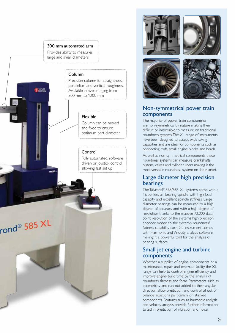
Non-symmetrical power train componentsThe majority of power train components are non-symmetrical by nature making them difficult or impossible to measure on traditional roundness systems. The XL range of instruments have been designed to accept wide swing capacities and are ideal for components such as connecting rods, small engine blocks and heads.
As well as non-symmetrical components these roundness systems can measure crankshafts, pistons, valves and cylinder liners making it the most versatile roundness system on the market.
Large diameter high precision bearings The Talyrond® 565/585 XL systems come with a frictionless air bearing spindle with high load capacity and excellent spindle stiffness. Large diameter bearings can be measured to a high degree of accuracy and with a high degree of resolution thanks to the massive 72,000 data point resolution of the systems high precision encoder. Added to the system’s roundness/flatness capability each XL instrument comes with Harmonic and Velocity analysis software making it a powerful tool for the analysis of bearing surfaces.
Small jet engine and turbine components Whether a supplier of engine components or a maintenance, repair and overhaul facility the XL range can help to control engine efficiency and improve engine build time by the analysis of roundness, flatness and form. Parameters such as eccentricity and run-out added to their angular direction allow prediction and control of out of balance situations particularly on stacked components. Features such as harmonic analysis and velocity analysis provide further information to aid in prediction of vibration and noise.
300 mm automated armProvides ability to measures large and small diameters
ColumnPrecision column for straightness, parallelism and vertical roughness. Available in sizes ranging from 300 mm to 1200 mm
FlexibleColumn can be moved and fixed to ensure optimum part diameter
ControlFully automated, software driven or joystick control allowing fast set up
22
For high precision inspection of roundness and cylindrical geometry of large, heavy or complex components
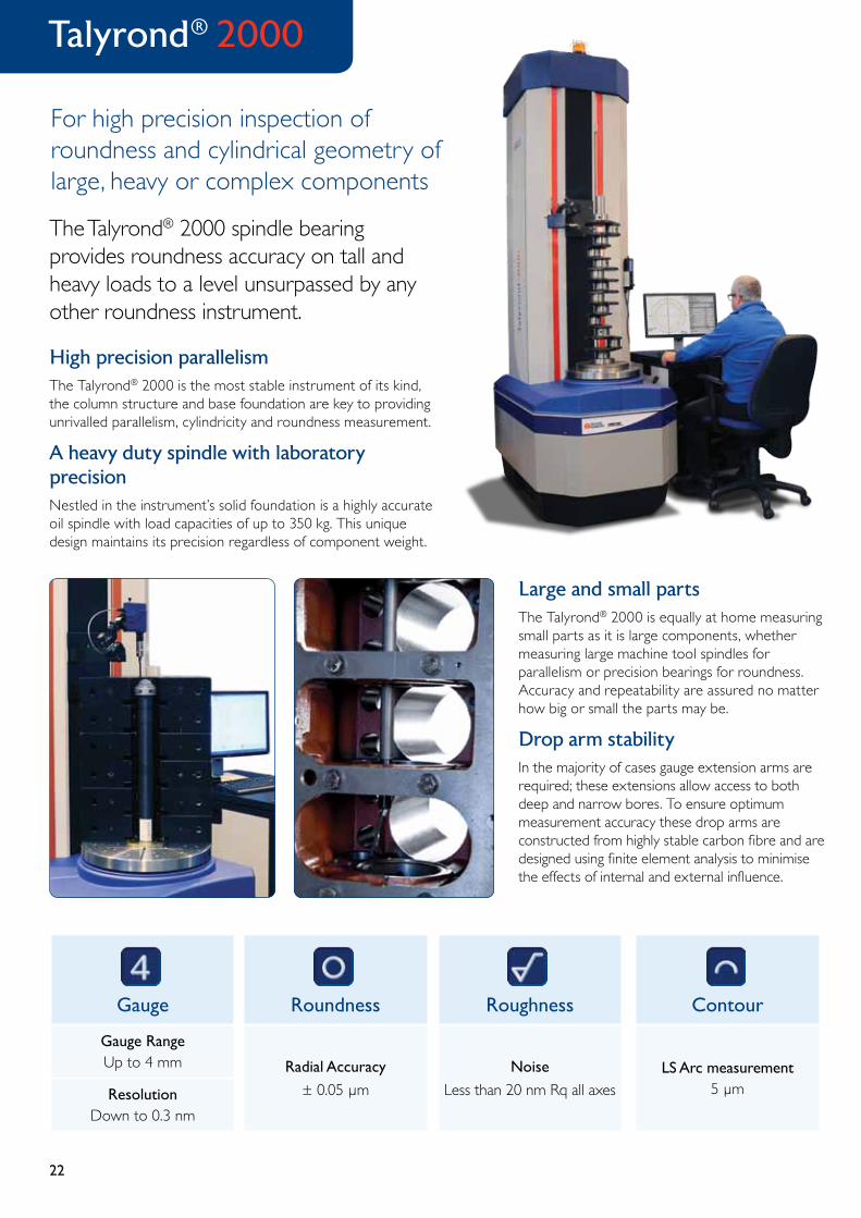
Talyrond® 2000
The Talyrond® 2000 spindle bearing provides roundness accuracy on tall and heavy loads to a level unsurpassed by any other roundness instrument.
High precision parallelismThe Talyrond® 2000 is the most stable instrument of its kind, the column structure and base foundation are key to providing unrivalled parallelism, cylindricity and roundness measurement.
A heavy duty spindle with laboratory precisionNestled in the instrument’s solid foundation is a highly accurate oil spindle with load capacities of up to 350 kg. This unique design maintains its precision regardless of component weight.
Roughness
Noise
Less than 20 nm Rq all axes
Contour
LS Arc measurement5 µm
Gauge
Gauge RangeUp to 4 mm
ResolutionDown to 0.3 nm
Roundness
Radial Accuracy
± 0.05 µm
Large and small parts
The Talyrond® 2000 is equally at home measuring small parts as it is large components, whether measuring large machine tool spindles for parallelism or precision bearings for roundness. Accuracy and repeatability are assured no matter how big or small the parts may be.
Drop arm stability
In the majority of cases gauge extension arms are required; these extensions allow access to both deep and narrow bores. To ensure optimum measurement accuracy these drop arms are constructed from highly stable carbon fibre and are designed using finite element analysis to minimise the effects of internal and external influence.
23
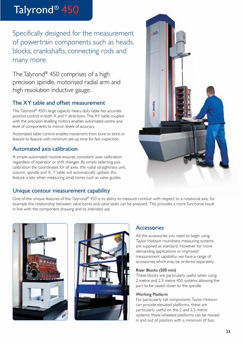
Specifically designed for the measurement of powertrain components such as heads, blocks, crankshafts, connecting rods and many more
Talyrond® 450
The Talyrond® 450 comprises of a high precision spindle, motorised radial arm and high resolution inductive gauge.
The XY table and offset measurementThe Talyrond® 450’s large capacity heavy duty table has accurate position control in both X and Y directions. The XY table coupled with the precision levelling motors enables automated centre and level of components to micron levels of accuracy.
Automated table control enables movement from bore to bore or feature to feature with minimum set-up time for fast inspection.
Automated axis calibrationA simple automated routine ensures consistent axes calibration regardless of operator or shift changes. By simply selecting axis calibration the coordinates for all axes, the radial straightness unit, column, spindle and X, Y table will automatically update; this feature is key when measuring small bores such as valve guides.
AccessoriesAll the accessories you need to begin using Taylor Hobson roundness measuring systems are supplied as standard. However for more demanding applications or improved measurement capability, we have a range of accessories which may be ordered separately.
Riser Blocks (500 mm)These blocks are particularly useful when using 2 metre and 2.5 metre 450 systems allowing the part to be raised closer to the spindle.
Working PlatformFor particularly tall components Taylor Hobson can provide elevated platforms, these are particularly useful on the 2 and 2.5 metre systems; these wheeled platforms can be moved in and out of position with a minimum of fuss.
Unique contour measurement capabilityOne of the unique features of the Talyrond® 450 is its ability to measure contour with respect to a rotational axis, for example the relationship between valve bores and valve seats can be analysed. This provides a more functional result in line with the component drawing and its intended use.

24
Profile graph
Clear detailed graph showing measurement area – excellent for visually identifying defects.
Bluetooth technology
Quick, reliable communication between traverse and display/control unit.
Measure
Tactile measurement button great for challenging orientations
Separates
The Duo splits into a display/control unit and traverse unit via a slide and lock mechanism.
Li-Poly battery
Most advanced rechargeable battery technology for unrivalled reliability and battery life.
Rubberised moulding
Enhanced durability and improved grip provides unbeatable protection in harsh shop floor environments.
USB mini charging port
Charge from mains or any standard USB charging port.
Simple 3-button navigation
Instant access to menu options and settings.
Diamond stylus and piezoelectric pick-up
The hard wearing, robust piezo-electric pick-up stylus with diamond tip assures very reliable measurement.
Surtronic® Duo
How it works
The hard-wearing diamond stylus is drawn across the part with a precision motorised traverse mechanism to ensure that the correct horizontal distance is travelled. Vertical movement of the stylus is detected by a high quality piezo-electric pick-up as it travels across peaks and valleys which converts mechanical movement into electrical signals. The electrical signal is digitised and sent to a microprocessor for instant calculation of surface parameters using standardised algorithms.
Handheld portable surface roughness testersThe Surtronic® Duo is a portable surface roughness tester that measure multiple roughness parameters with a 1-button click.
Roughness measurement parameters such as Ra, Rz, Rp, Rv and Rt are displayed on a brightly lit intuitive 2.4” LCD colour display. Its rechargeable battery operation makes it a convenient way of performing fast, easy and precise on-the-spot measurements.
25
Surtronic® S-100 series
Advanced surface finish analysis
TalyProfile is a dedicated PC based software package designed for use with Surtronic® S-100 series instruments. Three versions are available. TalyProfile “Lite” has all functions typically used for a shopfloor inspection, TalyProfile “Silver“ has enhanced features for R&W parameters, a statistics module and full report printing and TalyProfile “Gold“ has complete laboratory analysis functions.
Durable roughness testers for shop floor, industrial & inspection roomThe Surtronic® S-100 series offers a versatile solution for all your roughness requirements with a variety of systems and application specific accessories along with fixtures that can be tailored to your specific need.
In situ measurements - Monitor wear and roughness changes in situ during product’s life, e.g. monitoring changes in turbine blade roughness as an early warning sign for defects and efficiency losses.
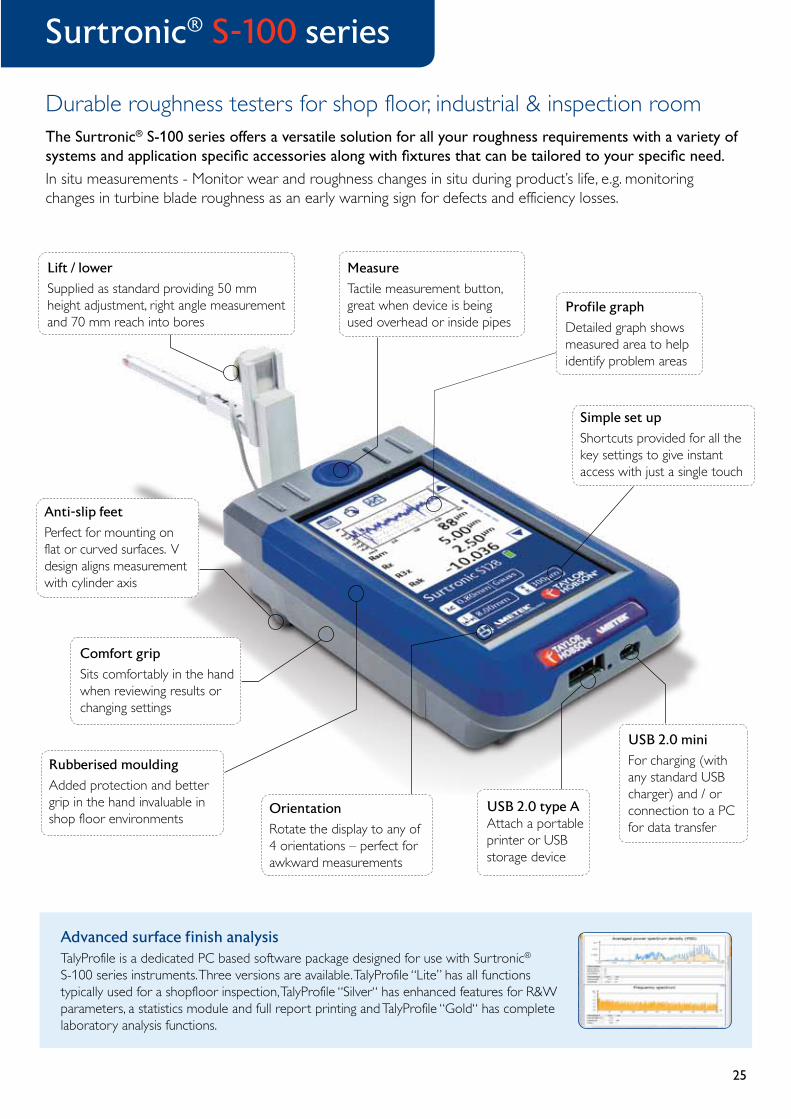
Simple set up
Shortcuts provided for all the key settings to give instant access with just a single touch
Profile graph
Detailed graph shows measured area to help identify problem areas
Measure
Tactile measurement button, great when device is being used overhead or inside pipes
Anti-slip feet
Perfect for mounting on flat or curved surfaces. V design aligns measurement with cylinder axis
Rubberised moulding
Added protection and better grip in the hand invaluable in shop floor environments
Orientation
Rotate the display to any of 4 orientations – perfect for awkward measurements
USB 2.0 type A Attach a portable printer or USB storage device
USB 2.0 mini
For charging (with any standard USB charger) and / or connection to a PC for data transfer
Lift / lower
Supplied as standard providing 50 mm height adjustment, right angle measurement and 70 mm reach into bores
Comfort grip
Sits comfortably in the hand when reviewing results or changing settings

26
Talyrond® 130
Diameter
Maximum part diameter
200 mm
Max load
Weight
20 kg
Gauge
Gauge RangeUp to 2 mm
ResolutionDown to 6 nm
Roundness
Radial Accuracy
± 25 nm
• Interactive programming with operator prompts
• Simple to set up and operate
• Rugged, compact construction for use anywhere in the plant
• Engraved scales for accurate positioning
• Self contained electronic interface module
• Accurate repeatable results
Talyrond® 130 incorporates a number of industry leading features that combine to deliver high accuracy, repeatability and ease of use.
The Talyrond® 130 is equipped with positive friction positioning controls on the column and the arm.
This direct drive response to movement of the large, ergonomic hand wheels feels precise and is precise. Drift, backlash and slop are greatly reduced without the need for clumsy, inefficient clamping devices.
Ultra roundness software
Ultra was developed first of all to function in accordance with the highest standards of metrology. That it turned out also to be clever, comprehensive and easy-to-use reflects the Taylor Hobson expertise at putting metrology to work in support of manufacturing.
• Total system control• Comprehensive analysis• Programmable measuring routines• Compliance with international standards• Computer aided center and level
Roundness result
Affordable and accurate roundness with precise positioning
Dimensions - 335 mm x 530 mm (W x H)

27
Talyrond® 131
Diameter
Maximum part diameter
370 mm
Cylindricity
Straightness
3 µm / 225 mm
Gauge
Gauge RangeUp to 2 mm
ResolutionDown to 6 nm
Roundness
Radial Accuracy
± 25 nm
For economical, high precision inspection of roundness and cylindricity
Talyrond® 131 systems incorporate a motorized column and radial arm for automatic measuring runs. Programmed routines shorten cycle times and minimize operator influence on results. The built in vertical reference unit extends capability to include cylindricity and total run out.
The degree of excellence for any gauging device is its range to resolution. Taylor Hobson gauge heads, with wide range and selectable resolution, vastly improve the measure of precision in your manufacturing process.
• Capacity for large components
• Functional, low maintenance construction
• Equally at home in the inspection room or on the production floor
• Simple to set up and operate
• Integrated electronic interface module
• Accurate repeatable results
Ultra roundness software
• Roundness on continuous surface
• Measurements on interrupted surfaces
• Cylindricity / Coaxiality / Concentricity
• Internationally recognized reference circles:
- Least Squares Circle - Minimum Zone Reference Circle - Minimum Circumscribed Circle - Maximum Inscribed Circle
Cylindricity result
Dimensions - 533 mm x 740 mm (W x H)

28
Speed (3 parts/minute including set-up)The most important benefit these systems offer is speed. In precision industries as manufacturing volumes increase, all too often the bottleneck is metrology. High measurement throughput using the Surtronic® R-100 Series, ensure higher sampling rates are achieved while also supporting increased manufacturing volumes.
Precision (±25 nm spindle accuracy)Although many times faster than traditional benchtop roundness systems, there is no loss of precision or accuracy. Full ISO compliant measurements can be taken with ±25 nm accuracy and 6 nm gauge resolution.
Robustness (suitable for 24/7 operation)All systems are designed for constant 24 hour, 7 days a week use in demanding shop floor environments; manufactured using only the most durable and hard wearing materials.
Ease of use (touchscreen software)The X-sight touch screen software platform with intuitive navigation make the Surtronic® roundness system as easy to use as a Sat Nav or Smartphone with everything you need at your fingertips.
X-sight touch screen software
High speed roundness systems for the bearings industry
A range of roundness products robust enough for the shop floor but accurate enough for any inspection room.
Working closely with bearings manufacturers, Taylor Hobson has focussed on the key attributes that are most important for quality control in today’s precision industries.
The new Surtronic® R-100 series instruments offer a flexible solution for all your roundness and form requirements with a variety of systems and application specific accessories along with fixtures that can be tailored to your specific need.
Grinding Turning Milling Honing
Surtronic® R-100 series
29
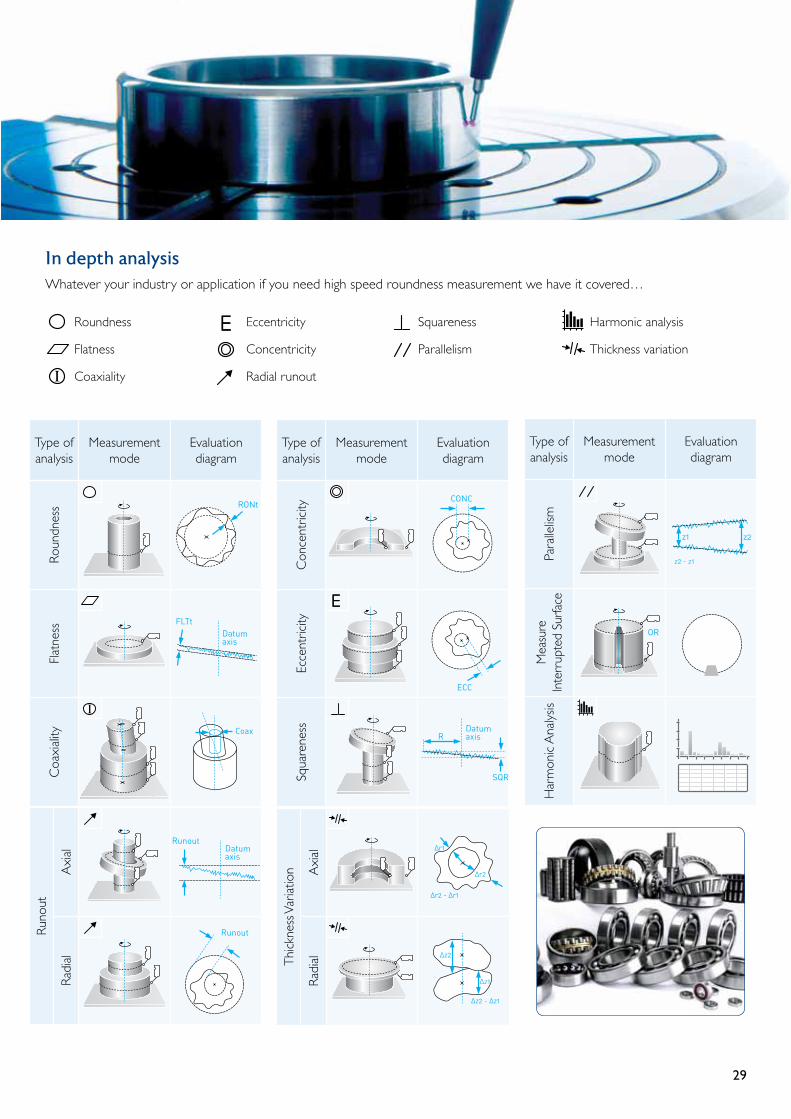
In depth analysis Whatever your industry or application if you need high speed roundness measurement we have it covered…
Type of analysis
Measurement mode
Evaluation diagram
Roun
dnes
sFl
atne
ssC
oaxi
ality
Flatness
Eccentricity (E)
Roundness
RunoutArial
RunoutRadial
Parallelism
Thicknessvariationdisc
Concentricity (C)
Thicknessvariation
Wall
Interuptedsurface
Harmonics
∆z2 - ∆z1
∆r2 - ∆r1
∆r2
∆r1
∆z2
∆z1
Coaxality
Squareness
Squareness
harmonicanalysis
L
Axis 2
Axis 1
N
1
1-
-N
Coax
∆r2-∆r1
∆r2
∆r1
Datum axis
z2z1
R
SQR
Datum axis
CONC
ECC
Datum axis
RONt
FLTt
Runout
Runout
z2 - z1
OR
Type of analysis
Measurement mode
Evaluation diagram
Con
cent
ricity
Ecce
ntric
itySq
uare
ness
Type of analysis
Measurement mode
Evaluation diagram
Para
llelis
mM
easu
re
Inte
rrup
ted
Surfa
ceH
arm
onic
Ana
lysis
Runo
ut
Axi
al
Radi
al
Flatness
Eccentricity (E)
Roundness
RunoutArial
RunoutRadial
Parallelism
Thicknessvariationdisc
Concentricity (C)
Thicknessvariation
Wall
Interuptedsurface
Harmonics
∆z2 - ∆z1
∆r2 - ∆r1
∆r2
∆r1
∆z2
∆z1
Coaxality
Squareness
Squareness
harmonicanalysis
L
Axis 2
Axis 1
N
1
1-
-N
Coax
∆r2-∆r1
∆r2
∆r1
Datum axis
z2z1
R
SQR
Datum axis
CONC
ECC
Datum axis
RONt
FLTt
Runout
Runout
z2 - z1
OR
Thic
knes
s Var
iatio
n Axi
alRa
dial
Flatness
Eccentricity (E)
Roundness
RunoutArial
RunoutRadial
Parallelism
Thicknessvariationdisc
Concentricity (C)
Thicknessvariation
Wall
Interuptedsurface
Harmonics
∆z2 - ∆z1
∆r2 - ∆r1
∆r2
∆r1
∆z2
∆z1
Coaxality
Squareness
Squareness
harmonicanalysis
L
Axis 2
Axis 1
N
1
1-
-N
Coax
∆r2-∆r1
∆r2
∆r1
Datum axis
z2z1
R
SQR
Datum axis
CONC
ECC
Datum axis
RONt
FLTt
Runout
Runout
z2 - z1
OR
Roundness
Flatness
Coaxiality
Eccentricity
Concentricity
Radial runout
Squareness
Parallelism
Harmonic analysis
Thickness variation

30
Precision shop floor solutions for surface finish
Combining industry leading specification with simplicity of operation for unbeatable practicality and value.
Housed in a rugged enclosure, the Intra has a proven history of maintaining accuracy of measurement without the need for constant maintenance or support.
Quality, flexibility and ease-of-use have enabled the Intra to become a shop-floor standard across a wealth of different industries.
Intra Touch / Ultra
Intra features and benefits
• 1 mm & 2 mm configurations Delivers surface finish measurement capability for precision machining and other shop floor applications.
• 50 mm horizontal traverse The unit combines both accuracy and portability.
• <0.30 µm / 50 mm straightness error The high accuracy traverse datum makes possible skidless measurement of surface finish and waviness.
• 0.5 µm horizontal data spacing Small components and features can be measured more effectively. Reduced run-up and run-down length further improve usability.
• Manual column For large or tall components the available manual column provides a stable, dedicated work station for improved throughput.
• Dual profile analysis* Allows comparison of measurements for wear, tolerancing, etc.
• TalyMap 3D analysis Software utility for topography applications; special hardware is also required.
Talyprofile software – comprehensive surface finish analysis
The Intra touch system includes everything needed for the assessment of surface finish. Fundamental roughness and waviness parameters are included, plus form error analysis, feature exclusion, zoom tool and analysis templates for shop floor applications.
• Form analysis Measure and evaluate radius, angle (slope) and dimension
• Simple user interface Combines simple calibration, measurement and analysis to deliver a true shop floor solution.
* Included with Talyprofile Gold

31
Portable shop floor contour solution, with 32 mm Z range
Cost effective, self-contained, robust portable contour solution with built in 90 mm Z height adjust and optional 350 mm column to accommodate large or tall components. Simple, single user interface for calibration, measurement and analysis.
Super precision mode delivers 24 nm Z resolution over a 6.4 mm Z range.
Intra Contour
Intra Contour features and benefits
• Z measurement range 32 mm / 122 nm resolution An ideal combination of measurement capability with plenty of range to accommodate even the largest features on typical components and enough resolution to detect the smallest contour deviations.
• <0.30 µm / 50 mm straightness error Extremely high accuracy straightness datum delivers dependable results over full 50 mm traverse length.
• Unique and patented calibration method Calibrate Z gain, arcuate motion and tip geometry with a single patented measurement on the 38.75 mm diameter calibration hemisphere.
• 0.5 µm horizontal data spacing Almost perfectly matched X and Z resolution deliver optimum angle and radius measurement.
• Contour analysis (basic and advanced configurations) Advanced contour analysis includes Auto-dimensioning, DXF import, Gothic Arch and full tolerancing.
• Gothic arch & v-groove analysis Advanced, automated analysis of common forms used for bearings and precision manufacturing.
• Auto tolerancing All features and dimensions can have tolerance limits set for automated pass / fail analysis.
Basic contour analysis includes all the standard features required for typical contour measurement including a full dimensioning toolkit for arc, radius, angle and dimension. Advanced contour expands this functionality for reverse engineering and automated quality control applications.
Advanced contour software - world leading automated contour analysis
• Auto dimensioning feature The software’s advanced algorithms can automatically detect features without user input or a CAD reference file.
• DXF import and comparison Allows comparison of measurements directly with design data from CAD.

32
Ultra Autocollimator
Measuring angle, straightness, flatness, squareness and parallelism
Taylor Hobson Autocollimators are used in conjunction with reflecting mirrors or surfaces for the accurate measurement of small angular deviations from a datum angle.
Alignment & level
Ultra High Precision Autocollimator with reference index table used to calibrate a polygon.
Their main applications include:
• Checking straightness of machine tool slideways• Checking dividing heads for their angular
displacements• Measuring very small angles• Measuring small linear displacements• Checking flatness of bed plates and surface
tables• Checking squareness of column to base• Checking parallelism of twin slide rails
The main advantages of autocollimators:
• High accuracy & wide range angle measurement• Easy to set up and operate• Calibration traceable to international standards• Choice of Visual or Electronic systems• Wide range of accessories and levels
Autocollimation in practice: checking, measuring, indexing & monitoring.
Used extensively in workshop, tool rooms, inspection departments and quality control laboratories throughout the world. Autocollimators are sensitive optical instruments designed for the accurate measurement of small angular displacements.

33
Laser Alignment System:The Micro Alignment Laser system is a laser measuring instrument equipped with the latest optical and electronic components for precise measurement of straightness, squareness and alignment. Typical applications include:
• Dynamic checking of assembled machine tool slideways for straightness/squareness
• Parallelism measurements and adjustment of tracks and guide•Monitoring of movement, deformation and deflection of structures
Talyvel Electronic Level:Used for checking and setting for example:
• Level: (to gravity)• Straightness: (of machine rails)• Flatness: (of granite tables)• Setting horizontal references
The Talyvel Electronic Level is universally accepted as the most accurate and stable level in the world with a resolution of 0.1 seconds.
Precision Microptic Clinometers:Used for checking and setting for example:
•Angle of machine vices•Angle of helicopter blades •Angle of guns•Checking aircraft wing flaps
The Taylor Hobson clinometers are simple and speedy instruments for checking and setting out angles from 0-360 degrees.
Micro Alignment Telescope:Used for checking and setting for example:
•Alignment: (series of bores or bearings)• Squareness: (column to a base)• Parallelism: (series of rollers)• Level/Flatness: (machine bed foundation)• Straightness: (rails or guideways)
The Micro Alignment Telescope is a highly versatile alignment instrument that generates a straight line reference from zero to infinity. With its wide range of accessories it forms a unique and comprehensive system for solving problems in a wide variety of applications and industries.
34
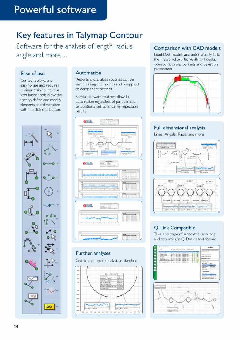
Key features in Talymap ContourSoftware for the analysis of length, radius, angle and more…
Comparison with CAD modelsLoad DXF models and automatically fit to the measured profile, results will display deviations, tolerance limits and deviation parameters.
Full dimensional analysisLinear, Angular, Radial and more
Q-Link CompatibleTake advantage of automatic reporting and exporting in Q-Das or text format.
Further analysesGothic arch profile analysis as standard
AutomationReports and analysis routines can be saved as single templates and re-applied to component batches.
Special software routines allow full automation regardless of part variation or positional set up ensuring repeatable results.
Contour software is easy to use and requires minimal training. Intuitive icon based tools allow the user to define and modify elements and dimensions with the click of a button.
Ease of use
Powerful software
35
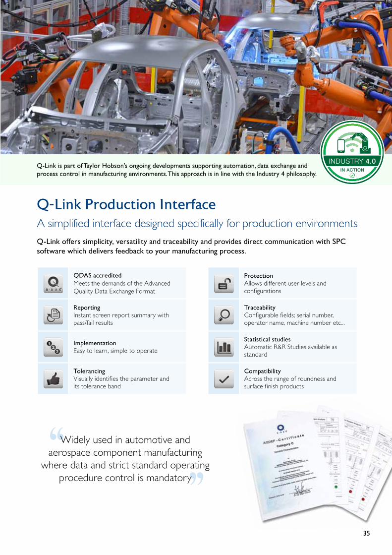
Q-Link Production InterfaceA simplified interface designed specifically for production environmentsQ-Link offers simplicity, versatility and traceability and provides direct communication with SPC software which delivers feedback to your manufacturing process.
‘‘‘‘Widely used in automotive and aerospace component manufacturing
where data and strict standard operating procedure control is mandatory
QDAS accreditedMeets the demands of the Advanced Quality Data Exchange Format
ReportingInstant screen report summary with pass/fail results
ImplementationEasy to learn, simple to operate
TolerancingVisually identifies the parameter and its tolerance band
ProtectionAllows different user levels and configurations
TraceabilityConfigurable fields; serial number, operator name, machine number etc...
Statistical studiesAutomatic R&R Studies available as standard
CompatibilityAcross the range of roundness and surface finish products
INDUSTRY 4.0IN ACTION
Q-Link is part of Taylor Hobson’s ongoing developments supporting automation, data exchange and process control in manufacturing environments. This approach is in line with the Industry 4 philosophy.

36
Ball screw and ball nuts analysis
Taylor Hobson has an in depth understanding of the wide range of applications for ball screw and lead screw actuator functionality; from aircraft control surfaces and landing gear, to precision movement of machine tools.
Spiral thread measurement orthogonal to functional surface
Advanced harmonic analysis of single lead
0 50 100 150 200 250 300 350 °
µm
-5
-4
-3
-2
-1
0
1
2
3
4
5
Talyrond® - Low noise helical harmonic and surface finish measurement
Key measurements for design and production
Taylor Hobson works with leading manufacturers of actuator screw shafts to develop unique measurement techniques for the industry.
This enables us to provide capability for the reliable inspection of production parts as well as providing detailed information needed to improve the designs and production processes.
Helical analysis• Helicalharmonicanalysis
• Velocityanalysis
• Ballscrew“noise”(RqandRdq)
• Harmonictolerancingandranking
• Helicalsurfacefinishandwaviness
• Leadrunout
• Leadaccuracy(deviationfromLS)
• Morphologicalfiltering*
Low noise analysis of single lead
Scale 1.0 µm/div
nm
deg
Bandwidth: 15-500 upr
* Use of a morphological filter to simulate the ball bearing path
Precise, low noise measurement
Talyrond® systems are highly stable, low noise measurement platforms. This makes it possible to clearly identify the characteristic harmonics of ball screws and ball nuts.
Traceability to international standards
Taylor Hobson’s harmonic standard validates the accuracy of ball screw and ball nut harmonic results.
It confirms the unique low noise capability and high bandwidth of the Talyrond® system. See page 10 for further information.
Ball screw alignmentTaylor Hobson’s Talyrond® systems ensure that the ball screw or ball nut is precisely aligned prior to measurement.
• Shaft alignment (C/L*)
• Thread alignment (Spiral C/L*)
* Centre and level

37
Form Talysurf® - Ball screw axial form measurement
‘‘
‘‘In depth analysis to reduce vibration and noise, improving performance and positional accuracy
Save time - measure along the full thread length with the Form Talysurf® then apply helix angle correction
Axial analysis• Gothicarchformandparameters
• Contactpointsandradii
• Threadaxialsurfacefinish
Nominal Ball Diameter
Al Ar
Bearing RaceZr Zl
Xr Xl
Rl Rr
Hc
X = Offset (Horiz)Z = Offset (Vert)R = RadiusA = Vertex AngleHc = Clearance
l = Left Arc r = Right Arc
α
Helix angle correction and thread analysis
Helix angle correction uses the axial measurement taken along the gothic thread profile, transforming it so that it represents a measurement taken perpendicular to the thread.
This allows for tolerancing and analysis of the profile against the design drawing and software simulation of the ball bearing fit within the gothic thread.
Critical gothic arc features such as contact angle, arc radii and distance between centres can be determined as shown in the diagram below.
Further analysis• Pitch circle diameter (PCD)• Bearingsurfaceroundness
• Bearingsurfacestraightness
• Bearingsurfacefinish
• Bearingwear(onusedsample)
• Alignmentmountaccuracy
• Threadrunout
• Shafttwistanalysis
Simulation of ball bearing fit in gothic thread
38
Taylor Hobson's Luphos non-contact probe has been incorporated into the Talyrond® high precision metrology platform to deliver world leading measurement capability.
The unparalleled measurement capability of the Talyrond® instruments combined with the accuracy and ease of use of the Luphos gauge provide unbeatable non-contact measurement up to 4 times faster.
Advantages of the Luphos probe system• Non-contact metrology
- Zero force measurement
• Nanometre accuracy - Unbeatable repeatability and resolution
• Large working distance and range - Nanometre precision with millimetre working range
• Absolute measurement - Does not need continuous signal so ideal for
measurement of interrupted surfaces
Twist Correlation - non-contact Vs. contact gauge
Non
-con
tact
mea
sure
men
t
Con
tact
mea
sure
men
t
Parameters Value Unit
Diameter 45.0 mm
Evaluation length 2.00 mm
Maximum wavelength 0.400 mm
Number of threads DG -8.0
Lead depth Dt 0.147 µm
Period length DP 0.346 mm
Theoretical supply cross section DF 21.4 µm2
Theoretical supply cross section per turn DFu 171 µm2/U
Contact length in percent DLu 35.3 %
Lead angle Dy -1.12 °
Parameters Value Unit
Diameter 45.0 mm
Evaluation length 2.00 mm
Maximum wavelength 0.400 mm
Number of threads DG -8.0
Lead depth Dt 0.148 µm
Period length DP 0.354 mm
Theoretical supply cross section DF 22.4 µm2
Theoretical supply cross section per turn DFu 179 µm2/U
Contact length in percent DLu 37.9 %
Lead angle Dy -1.15 °
Using the Twist analysis approach defined in MBN 31007-7 it is possible to get excellent correlation between non-contact and contact measurement.
The big advantage of the non-contact probe is the reduced time for the whole 360 degree measurement.
Measurement and analysis of Twist• The surface finish of a rotating shaft can give rise to seal leakage
or premature failure. Twist analysis is important in the early detection of any issues.
• Twist analysis quantifies the spiralling marks on the shaft
- Developed and patented by Daimler - It uses a 3D map of the surface and filters out all the non
relevant frequencies to leave the twist data - Measurements can be taken with suitable Talyrond® or
Form Talysurf® instruments. Twist results after filtering
High speed Twist measurement
39
Customer requirementsThis manufacturer in recent years has been supplying an increasing number of fuel injector pumps, as more car manufacturers use purchased pumps instead of designing and building their own. Inspections of the cylinder heads are currently completed by different instruments to quantify roundness, concentricity, seat angle and seat form.
With production numbers running far in excess of 300,000 and different fixtures having to be used to measure the same part, a new technique is required to measure all these features with one instrument and fewer fixtures, to specifically reduce time and manual effort and to increase throughput.
Background – how does a fuel injection pump work?In order for an injection action to occur, a build-up of pressure is required. In the Common Rail Accumulator Injection system, the actual build-up of injection pressure is separate from the injection action itself. Pressure is generated in the Rail (also known as an accumulator) from a high pressure pump. This high-pressure pump is driven by the crankshaft of the engine and supplies fuel to the rail at 1,600 bar, even at low engine speeds. The high pressure produces a very fine atomisation of the fuel leading to better and cleaner combustion. As the rail is pressured all the time, the fuel supply can be optimised independently to each injector. The time and duration of fuel injection is controlled by the ECU and can be controlled precisely to optimise combustion and emissions.
Benefits of the common rail principle compared with conventional diesel engines are lower engine noise levels, stronger performance and greater efficiency leading to lower emissions and enhanced fuel economy.
Because of the high pressures involved in this mechanism the sealing faces of the pump are critical in terms of form, angle and surface finish and require tight control.
The solution – TalyMasterTalymaster is a brand new inspection concept combining roughness, roundness and contour on a fully automated inspection system. The instrument incorporates complete part manipulation ensuring high throughput and significantly reduced inspection costs compared to the traditional inspection methods.
The cylinder heads were mounted on a magnetic plate (dedicated fixtures would be required in a production environment) and under program control roundness, concentricity, straightness, parallelism and seat angle were measured and quantified. Only four cylinder heads were supplied, though more components can be fixtured if required.
A critical feature on the cylinder heads is to be able to migrate from one hole to another without removing the part. Using the TalyMaster XY stage it is now possible to mount several components at one time, measure all features on each part as well as compute the distance between features.
www.taylor-hobson.com © Taylor Hobson 2012
Cylinder Head – Fuel Injection Pump
TalyMaster
Greg Roper, Applications Engineer
Figure 1: Several components can be mounted at one time
Application note A127: Cylinder head – fuel injection pump
A127 - Cylinder Head –Fuel Injection Pump
A129 - Roller bearings
Application notes
Further reading
A149 - Ball screws and lead screws
A151 - High precision multi-part measurement
IntroductionTaylor Hobson works with leading manufacturers of actuator components to develop unique measurement techniques for the industry. This enables us to provide capability for the reliable inspection of production parts as well as providing detailed information needed to improve the designs and production process.
We understand ball screws, lead screws and bearings the factors affecting their performance, many of which documented in ISO, DIN, ANSI and JIS standards. Inspection of these factors is fundamental to ensure product specifications are achieved.
Ball screws and lead screws are routinely used for a wide range of applications from aircraft control surfaces and landing gear, to precision movement of machine tools, as well as various automotive applications. Each of these applications has a different set of priorities in the requirements for actuation which need to be accommodated for.
Ball and lead screw applications Ball and lead screws are used to convert rotational and linear motion in a variety of applications, the most common being linear actuators such as the ones used for aircraft control surfaces
These types of actuators are used in a range of applications with as big a range of requirements. The highest precision parts are required for aerospace and machine tool slides. Other less demanding example applications include automatic gates.
The same components are also used in other applications such as steering wheel columns to provide a smooth, linear motion as the steering wheel is turned.
www.taylor-hobson.com © Taylor Hobson 2015
Talyrond, Form Talysurf
Inspection of ball and lead screw actuator components Robert Burton, Applications Engineer
Application note A149: Lead and ball screws
IntroductionTaylor Hobson has a large history of working closely with manufacturers of high precision parts that are mass produced on a large scale. This has led to the development of a multi-part measurement technique that allows for inspection of over 30 parts with no operator intervention or loss of accuracy. The rotary stage can be easily attached, transforming the Talyrond® 500 HS into the ideal multi-part measurement system.
Easy loading of samples onto bespoke fixture
Place carousel onto Talyrond® 500 HS
Rapid multi-part measurement
Talyrond® 585 HS system with rotary stage
Bespoke fixtures to cater for different parts
Transform your Talyrond® 500 HS
To transform your instrument into a multi-part measurement system, simply place the carousel’s three feet in the tables V grooves and connect the power.
To remove the carousel system, disconnect the socket and lift off the table. Please note that no software configuration is required during the setup procedure.
Connect power
AdvantagesWith the high volume of precision parts that are being produced it is vital that a simple, quick and accurate solution is available. The easy loading of samples onto bespoke fixtures is a major benefit to customers looking for fast and reliable answers. Another advantage is that this multi-part measurement is fully automated. A high throughput is ensured with one measurement cycle taking a fraction of the time of that of traditional methods.
www.taylor-hobson.com © Taylor Hobson 2016
Talyrond® 500 HS - Rotary stage
High precision multi-part measurement James Porter, Applications Engineer
Application note A151: Exceptional accuracy and repeatability for multi-part measurements

The metrology experts
Taylor Hobson is world renowned as a manufacturer of precision measuring instruments used for inspection in research and production facilities. Our equipment performs at nanometric levels of resolution and accuracy.
To complement our precision manufacturing capability we also offer a host of metrology support services to provide our customers with complete solutions to their measuring needs and total confidence in their results.
www.taylor-hobson.com
Service departmentEmail: [email protected] Tel: +44 (0)116 246 2900
• Preventativemaintenance – protect your metrology investment with an Amecare support agreement
Sales departmentEmail: [email protected] Tel: +44 (0)116 246 2034
• Designengineering – special purpose, dedicated metrology systems for demanding applications
• Precisionmanufacturing – contract machining services for high precision applications and industries
CentreofExcellencedepartmentEmail: [email protected] Tel: +44 (0)116 276 3779
•Inspectionservices – measurement of your production parts by skilled technicians using industry leading instruments in accord with ISO standards
•Metrologytraining – practical, hands-on training courses for roundness and surface finish conducted by experienced metrologists
• Operatortraining – on-site instruction will lead to greater proficiency and higher productivity
• UKAScalibrationandtesting – certification for artifacts or instruments in our laboratory or at customer’s site
0026 2624
Copyright© 2017 • Taylor Hobson
Innovation - Product Solutions_11/2017
© DiskArt™ 1988
TaylorHobsonUK (GlobalHeadquarters)PO Box 36, 2 New Star RoadLeicester, LE4 9JD, England Tel: +44 (0)116 276 3771Fax: +44 (0)116 246 [email protected]
Taylor Hobson China [email protected]
ShanghaiOfficePart A1, A4. 2nd Floor, Building No. 1, No. 526 Fute 3rd Road East, Pilot Free Trade Zone, Shanghai, 200131, China Tel: +86 21 5868 5111-110 Fax: +86 21 5866 0969-110
BeijingOfficeWestern Section, 2nd Floor, Jing Dong Fang Building (B10), No. 10, Jiu Xian Qiao Road, Chaoyang District, Beijing, 100015, China Tel: +86 10 8526 2111Fax: +86 10 8526 2141
ChengduOfficeUnit 9-10,10th Floor9/F, Hi-tech Incubation Park, No.26 West Jinyue Road, Chengdu. 610041, China Tel: +86 28 8675 8111Fax: +86 28 8675 8141
GuangzhouOfficeRoom 810 Dongbao Plaza, No.767 East Dongfeng Road, Guangzhou, 510600, China Tel: +86 20 8363 4768Fax: +86 20 8363 3701
Taylor Hobson FranceRond Point de l’Epine ChampsBatiment D, 78990 Elancourt, France Tel: +33 130 68 89 30Fax: +33 130 68 89 [email protected]
Taylor Hobson GermanyRudolf-Diesel-Straße 16 D-64331 Weiterstadt, Germany Tel: +49 6150 543 0Fax: +49 6150 543 [email protected]
TaylorHobsonIndiaDivyasree NR Enclave, 4th Floor, Block A,Plot No. 1, EPIP Industrial Area,Whitefield, Bengaluru - 560066, IndiaTel: +91 80 6782 3346Fax: +91 80 6782 3232 [email protected]
TaylorHobsonItalyVia De Barzi, 20087 Robecco sul Naviglio, Milan, Italy Tel: +39 02 946 93401 Fax: +39 02 946 [email protected]
Taylor Hobson Japan3F Shiba NBF Tower, 1-1-30, Shiba Daimon Minato-ku, Tokyo 105-0012, Japan Tel: +81 36809 2406Fax: +81 36809 [email protected]
TaylorHobsonKorea#309, 3rd FL, Gyeonggi R&DB Center, 105, Gwanggyo-ro,Yeongtong-gu, Suwon-si, Gyeonggi-do, Korea, 16229 Tel: +82 31 888 5255 Fax: +82 31 888 5228 [email protected]
TaylorHobsonMexicoAcceso III No. 16 Nave 3 Parque Ind. Benito Juarez Queretaro, Qro. Mexico C.P. 76120, MexicoTel: +52 442 426 4480 Fax: +52 442 295 [email protected]
Taylor Hobson SingaporeAMETEK singapore, 10 Ang Mo Kio Street 65, No. 05-12 Techpoint, Singapore 569059 Tel: +65 6484 2388 Ext 120Fax: +65 6484 2388 Ext 120 [email protected]
Taylor Hobson Taiwan10F-5, No.120, Sec. 2, Gongdao Wu Rd., Hsinchu City 30072, Taiwan Tel: +886 3 575 0099 Ext 301Fax: +886 3 575 0799 [email protected]
TaylorHobsonUSA27755 Diehl Road, Suite 300,Warrenville, IL 60555, USA Tel: +1 630 621 3099 Fax: +1 630 231 [email protected]