INND-TS56 Series 0.56” Through Hole Single Digit Display ... · INND-TS56 Series 0.56” Through...
12
INND-TS56 Series 0.56” Through Hole Single Digit Display Inolux Corporation Proprietary & Confidential July12, 2017 www.inolux-corp.com Page 1 Features • 0.56” (14.20mm) Matrix Height • Single Digit Display • Black/Grey Face , White Segment • IC compatible, Easy assembly • Dynamic drive connect • RoHS Compliant, Pb Free Applications • Consumer Electronics • Industrial Equipment Description The INND-TS56 series is a 0.56” single digit display. It is a through hole type LED display which can be used in various applications. Common Anode Common Cathode Figure 1. INND-TS56 series Internal Circuit Diagram Package Dimensions Figure 2. INND-TS56 series Package Dimensions
Transcript of INND-TS56 Series 0.56” Through Hole Single Digit Display ... · INND-TS56 Series 0.56” Through...

INND-TS56 Series0.56” Through Hole Single Digit Display
Inolux Corporation Proprietary & Confidential
July12, 2017www.inolux-corp.com
Page 1
Features
• 0.56” (14.20mm) Matrix Height
• Single Digit Display
• Black/Grey Face , White Segment
• IC compatible, Easy assembly
• Dynamic drive connect
• RoHS Compliant, Pb Free
Applications
• Consumer Electronics
• Industrial Equipment
Description
The INND-TS56 series is a 0.56” single digit display. It
is a through hole type LED display which can be used
in various applications.
Common Anode Common Cathode
Figure 1. INND-TS56 series Internal Circuit Diagram
Package Dimensions
Figure 2. INND-TS56 series Package Dimensions

INND-TS56 Series0.56” Through Hole Single Digit Display
Inolux Corporation Proprietary & Confidential
July12, 2017www.inolux-corp.com
Page 2
Absolute Maximum Rating at 25 oC (Note 1)
Product (Per Segment)
Emission Color Technology Pd (mW) IF (mA) IFP* (mA) VR (V)
Derate From 25°C (mA/°C)
TOP (oC) TST (oC)
INND-TS56YGXX Yellow Green AlGaInP 70 25 90 5 0.33 -35oC~+85oC -35oC~+85oC
INND-TS56YXX Yellow AlGaInP 70 25 90 5 0.33 -35oC~+85oC -35oC~+85oC
INND-TS56AXX Amber AlGaInP 70 25 90 5 0.33 -35oC~+85oC -35oC~+85oC
INND-TS56RXX Red AlGaInP 70 25 90 5 0.33 -35oC~+85oC -35oC~+85oC
INND-TS56DRXX Deep Red AlGaInP 70 25 90 5 0.33 -35oC~+85oC -35oC~+85oC
INND-TS56GXX Green InGaN 114 30 100 5 0.4 -35oC~+85oC -35oC~+85oC
INND-TS56BXX Blue InGaN 114 30 100 5 0.4 -35oC~+85oC -35oC~+85oC
INND-TS56WXX White InGaN 114 30 100 5 0.4 -35oC~+85oC -35oC~+85oC
Notes 1. Condition for IFP is pulse of 1/10 duty and 0.1msec width

INND-TS56 Series0.56” Through Hole Single Digit Display
Inolux Corporation Proprietary & Confidential
July12, 2017www.inolux-corp.com
Page 3
Electrical Characteristics TA = 25°C (Note 1)
Product (Per Segment)
Emission Color
VF(V)@20mA λ(nm)@20mA I*V(mcd)@10mA IR(μA)@VR=5V IV-M @IF =10mA
min typ. max λD λP min typ. max max max
INND-TS56YGXX Yellow Green - 2.0 2.8 570 572 - 15 - 100 2:1
INND-TS56YXX Yellow - 2.0 2.8 590 592 - 50 - 100 2:1
INND-TS56AXX Amber - 2.0 2.8 605 612 - 70 - 100 2:1
INND-TS56RXX Red - 2.0 2.8 630 644 - 30 - 100 2:1
INND-TS56DRXX Deep Red - 2.0 2.8 645 660 - 25 - 100 2:1
INND-TS56GXX Green - 3.2 3.8 525 - - 218 - 100 2:1
INND-TS56BXX Blue - 3.2 3.8 465 - - 27 - 50 2:1
INND-TS56WXX White - 3.2 3.8 X: 0.27 Y: 0.25 - - 130 - 50 2:1
Notes 1. Performance guaranteed only under conditions listed in above tables.
ESD Precaution ATTENTION: Electrostatic Discharge (ESD) protection
The symbol above denotes that ESD precaution is needed. ESD protection for GaP and AlGaAs based chips is necessary even though they are relatively safe in the presence of low static-electric discharge. Parts built with AlInGaP, GaN, or/and InGaN based chips are STATIC SENSITIVE devices. ESD precaution must be taken during design and assembly. If manual work or processing is needed, please ensure the device is adequately protected from ESD during the process.
Please be advised that normal static precautions should be taken in the handling and assembly of this device to prevent damage or degradation which may be induced by electrostatic discharge (ESD).

INND-TS56 Series0.56” Through Hole Single Digit Display
Inolux Corporation Proprietary & Confidential
July12, 2017www.inolux-corp.com
Page 4
Characteristic Curves for YG, Y, A, R, DR, G

INND-TS56 Series0.56” Through Hole Single Digit Display
Inolux Corporation Proprietary & Confidential
July12, 2017www.inolux-corp.com
Page 5
Characteristic Curves for B
INND-TS56 Series0.56” Through Hole Single Digit Display
Inolux Corporation Proprietary & Confidential
July12, 2017www.inolux-corp.com
Page 6
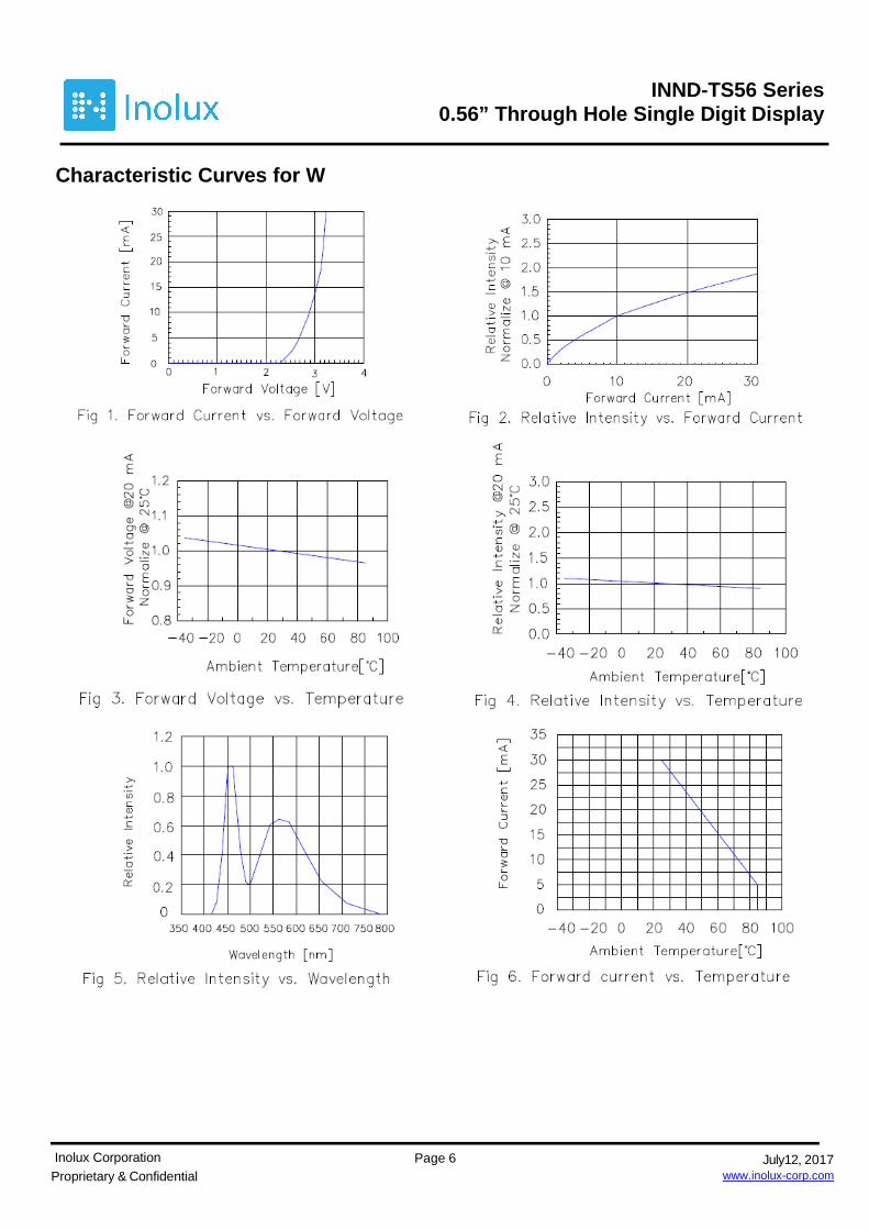
Characteristic Curves for W

INND-TS56 Series0.56” Through Hole Single Digit Display
Inolux Corporation Proprietary & Confidential
July12, 2017www.inolux-corp.com
Page 7
Chromaticity Bin (for White only)

INND-TS56 Series0.56” Through Hole Single Digit Display
Inolux Corporation Proprietary & Confidential
July12, 2017www.inolux-corp.com
Page 8
Ordering Information
Product Emission Color Technology I*V(mcd) @10mA
VF(V) @20mA Polarity
Face Color
Orderable Part Number
INND-TS56YGXX Yellow Green AlGaInP 15 2.0
Common Anode Black INND-TS56YGAB
Common Cathode
Black INND-TS56YGCB
Common Anode Grey INND-TS56YGAG
Common Cathode Grey INND-TS56YGCG
INND-TS56YXX Yellow AlGaInP 50 2.0
Common Anode Black INND-TS56YAB
Common Cathode Black INND-TS56YCB
Common Anode Grey INND-TS56YAG
Common Cathode
Grey INND-TS56YCG
INND-TS56AXX Amber AlGaInP 70 2.0
Common Anode
Black INND-TS56AAB
Common Cathode Black INND-TS56ACB
Common Anode Grey INND-TS56AAG
Common Cathode Grey INND-TS56ACG
INND-TS56RXX Red AlGaInP 30 2.0
Common Anode Black INND-TS56RAB
Common Cathode Black INND-TS56RCB
Common Anode Grey INND-TS56RAG
Common Cathode Grey INND-TS56RCG

INND-TS56 Series0.56” Through Hole Single Digit Display
Inolux Corporation Proprietary & Confidential
July12, 2017www.inolux-corp.com
Page 9
Product Emission Color Technology I*V(mcd)
@10mA VF(V)
@20mA Polarity Face Color
Orderable Part Number
INND-TS56DRXX Deep Red AlGaInP 25 2.0
Common Anode Black INND-TS56DRAB
Common Cathode Black INND-TS56DRCB
Common Anode Grey INND-TS56DRAG
Common Cathode Grey INND-TS56DRCG
INND-TS56GXX Green InGaN 218 3.2
Common Anode Black INND-TS56GAB
Common Cathode
Black INND-TS56GCB
Common Anode
Grey INND-TS56GAG
Common Cathode Grey INND-TS56GCG
INND-TS56BXX Blue InGaN 27 3.2
Common Anode Black INND-TS56BAB
Common Cathode Black INND-TS56BCB
Common Anode Grey INND-TS56BAG
Common Cathode Grey INND-TS56BCG
INND-TS56WXX White InGaN 130 3.2
Common Anode Black INND-TS56WAB
Common Cathode Black INND-TS56WCB
Common Anode Grey INND-TS56WAG
Common Cathode Grey INND-TS56WCG

INND-TS56 Series0.56” Through Hole Single Digit Display
Inolux Corporation Proprietary & Confidential
July12, 2017www.inolux-corp.com
Page 10
Label Specifications
Inolux P/N:
I N N D - T S 5 6 X X X - X X X X
Inolux
Display
Type
Display Type Dimension Color Polarity Face
Color
Customized
Stamp-off
ND =
Numeric
Display
T: Through hole
S: Single
56 = 0.56”
Display Height
YG: 570 nm
Y: 590 nm
A: 605 nm
R: 630 nm
DR: 660 nm
G: 525 nm
B: 465 nm
W:
X: 0.27
Y: 0.25
A = Common
Anode
C=Common
Cathode
B = Black
G = Grey
Lot No.:
Z 2 0 1 7 01 24 001
Internal
Tracker Year (2017, 2018, …..) Month Date Serial

INND-TS56 Series0.56” Through Hole Single Digit Display
Inolux Corporation Proprietary & Confidential
July12, 2017www.inolux-corp.com
Page 11
Reflow Soldering
Soldering Iron Basic Spec is ≦ 4 sec. when 260°C (+10°C � -1 second). Power dissipation of Iron should be
less than 15W. Surface temperature should be under 230°C
Rework Rework should be completed within 4 second under 245°C

INND-TS56 Series0.56” Through Hole Single Digit Display
Inolux Corporation Proprietary & Confidential
July12, 2017www.inolux-corp.com
Page 12
Revision History Changes since last revision Page Version No. Revision Date Initial Release 1.0 07-12-2017
DISCLAIMER
INOLUX reserves the right to make changes without further notice to any products herein to improve reliability, function or design. INOLUX does not assume any liability arising out of the application or use of any product or circuit described herein; neither does it convey any license under its patent rights, nor the rights of others.
LIFE SUPPORT POLICY
INOLUX’s products are not authorized for use as critical components in life support devices or systems without the express written approval of the President of INOLUX or INOLUX CORPORATION. As used herein: 1. Life support devices or systems are devices or systems which, (a) are intended for surgical implant into the body, or (b) support or sustain life, and (c) whose failure to perform when properly used in accordance with instructions for use provided in the labeling, can be reasonably expected to result in a significant injury of the user. 2. A critical component in any component of a life support device or system whose failure to perform can be reasonably expected to cause the failure of the life support device or system, or to affect its safety or effectiveness.