Search & Filter Interface Round Up - Usability Marathon - Cueva
1
E 7.
584.
1/11
.16
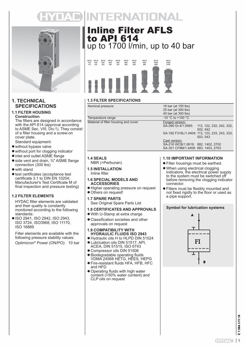
Inline Filter AFLS to API 614 up to 1700 l/min, up to 40 bar
1. TECHNICAL SPECIFICATIONS
1.1 FILTER HOUSINGConstruction The filters are designed in accordance with the API 614 (approval according to ASME Sec. VIII, Div.1). They consist of a filter housing and a screw-on cover plate.Standard equipment:
without bypass valve without port for clogging indicator inlet and outlet ASME flange side vent and drain, ¾" ASME flange
connection (300 lbs) with stand test certificates (acceptance test
certificate 3.1 to DIN EN 10204; Manufacturer's Test Certificate M of final inspection and pressure testing)
1.2 FILTER ELEMENTSHYDAC filter elements are validated and their quality is constantly monitored according to the following standards:
ISO 2941, ISO 2942, ISO 2943, ISO 3724, ISO3968, ISO 11170, ISO 16889Filter elements are available with the following pressure stability values:Optimicron® Power (ON/PO): 10 bar
1.4 SEALSNBR (=Perbunan)
1.5 INSTALLATIONInline filter
1.6 SPECIAL MODELS AND ACCESSORIES
Higher operating pressure on request Others on request!1.7 SPARE PARTS
See Original Spare Parts List1.8 CERTIFICATES AND APPROVALS With U-Stamp at extra charge Classification societies and other
approvals on request1.9 COMPATIBILITY WITH
HYDRAULIC FLUIDS ISO 2943 Hydraulic oils H to HLPD DIN 51524 Lubrication oils DIN 51517, API,
ACEA, DIN 51515, ISO 6743 Compressor oils DIN 51506 Biodegradable operating fluids
VDMA 24568 HETG, HEES, HEPG Fire-resistant fluids HFA, HFB, HFC
and HFD Operating fluids with high water
content (>50% water content) and CLP oils on request
1.10 IMPORTANT INFORMATION Filter housings must be earthed. When using electrical clogging
indicators, the electrical power supply to the system must be switched off before removing the clogging indicator connector.
Filters must be flexibly mounted and not fixed rigidly to the floor or used as a pipe support.
1.3 FILTER SPECIFICATIONS Nominal pressure 16 bar (at 150 lbs) 25 bar (at 300 lbs) 40 bar (at 300 lbs) Temperature range -10 °C to +100 °C Material of filter housing and cover Forged version: SA-266 Gr.4/1.0565: 112, 122, 232, 242, 332, 502, 542 SA-182 F316L/1.4404: 113, 123, 233, 243, 333, 503, 543 Cast version: SA-216 WCB/1.0619: 882, 1402, 2702 SA-351 CF8M/1.4408: 883, 1403, 2703
Symbol for lubrication systems
E 7.
584.
1/11
.16
AFLS 112/ 113
AFLS 122/ 123
AFLS 242/ 243
AFLS 332/ 333
AFLS 502/ 503
AFLS 542/ 543
AFLS 882/ 883
AFLS 1402/ 1403
AFLS 2702/ 2703
AFLS 232/ 233
2
E 7.
584.
1/11
.16
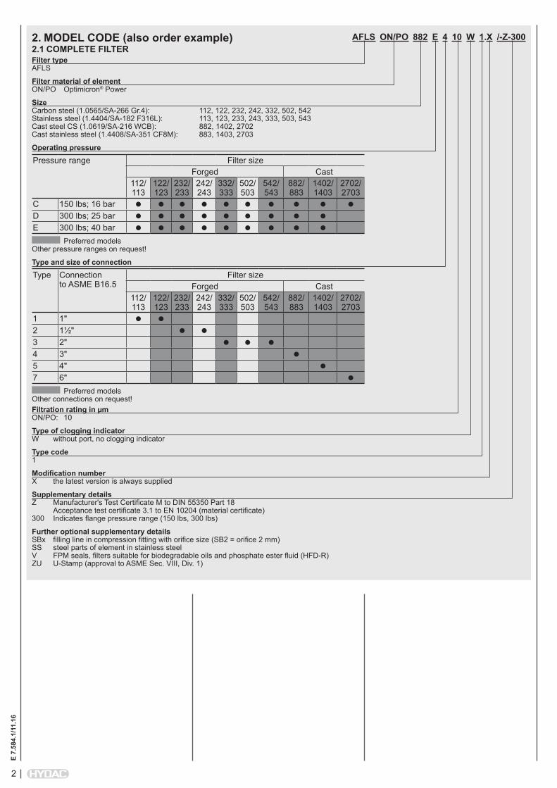
AFLS ON/PO 882 E 4 10 W 1.X /-Z-300
Filter type AFLS
Filter material of element ON/PO Optimicron® Power
Size Carbon steel (1.0565/SA-266 Gr.4): 112, 122, 232, 242, 332, 502, 542 Stainless steel (1.4404/SA-182 F316L): 113, 123, 233, 243, 333, 503, 543 Cast steel CS (1.0619/SA-216 WCB): 882, 1402, 2702 Cast stainless steel (1.4408/SA-351 CF8M): 883, 1403, 2703
Operating pressure
Pressure range Filter sizeForged Cast
112/ 113
122/ 123
232/ 233
242/ 243
332/ 333
502/ 503
542/ 543
882/ 883
1402/ 1403
2702/ 2703
C 150 lbs; 16 bar D 300 lbs; 25 bar E 300 lbs; 40 bar
Preferred models Other pressure ranges on request!
Type and size of connection Type Connection
to ASME B16.5Filter size
Forged Cast112/ 113
122/ 123
232/ 233
242/ 243
332/ 333
502/ 503
542/ 543
882/ 883
1402/ 1403
2702/ 2703
1 1" 2 1½" 3 2" 4 3" 5 4" 7 6"
Preferred models Other connections on request!Filtration rating in µm ON/PO: 10
Type of clogging indicator W without port, no clogging indicator
Type code 1
Modification number X the latest version is always supplied
Supplementary details Z Manufacturer's Test Certificate M to DIN 55350 Part 18 Acceptance test certificate 3.1 to EN 10204 (material certificate) 300 Indicates flange pressure range (150 lbs, 300 lbs)
Further optional supplementary details SBx filling line in compression fitting with orifice size (SB2 = orifice 2 mm) SS steel parts of element in stainless steel V FPM seals, filters suitable for biodegradable oils and phosphate ester fluid (HFD-R) ZU U-Stamp (approval to ASME Sec. VIII, Div. 1)
2. MODEL CODE (also order example)2.1 COMPLETE FILTER
3
E 7.
584.
1/11
.16
0880 A 010 ON/POSize 0110, 0120, 0230, 0240, 0330, 0500, 0540, 0880, 1400, 2700Type A API versionFiltration rating in µm ON/PO: 010Filter material of element ON/PO Optimicron® PowerSupplementary details SS Steel parts of element in stainless steel
2.2 REPLACEMENT ELEMENT
2.3 CLOGGING INDICATOR (OPTIONAL) VM 2 D . X /-L24Type VM Differential pressure measurementPressure setting 2 standard 2 bar, others on requestType Y plastic blanking plug in indicator port A steel blanking plug in indicator port B visual C electrical D visual/electricalModification number X the latest version is always suppliedSupplementary details L... light with appropriate voltage (24V, 48V, 110V, 220V) LED 2 light-emitting diodes up to 24 Volt V FPM seals
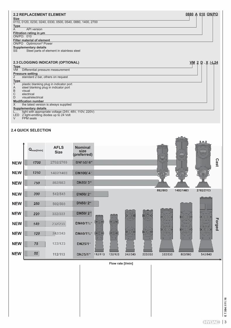
2.4 QUICK SELECTION
AFLS Size
Nominal size
(preferred)
Flow rate [l/min]
Cast
Forged
Qmax[l/min]
4
E 7.
584.
1/11
.16
0
0.02
0.04
0.06
0.08
0.1
0.12
0.14
0.16
0.18
0.2
0 50 100 150 200 250
0
0.05
0.1
0.15
0.2
0.25
0.3
0 50 100 150 200 250 300
0
0.02
0.04
0.06
0.08
0.1
0.12
0.14
0.16
0.18
0.2
0 50 100 150 200 250
0
0.02
0.04
0.06
0.08
0.1
0.12
0.14
0.16
0.18
0.2
0 20 40 60 80 100 120 140
0
0.05
0.1
0.15
0.2
0.25
0 20 40 60 80 100 120 140 160 180
0
0.05
0.1
0.15
0.2
0.25
0.3
0 10 20 30 40 50 60 70 80 90
0
0.05
0.1
0.15
0.2
0.25
0.3
0 10 20 30 40 50 60
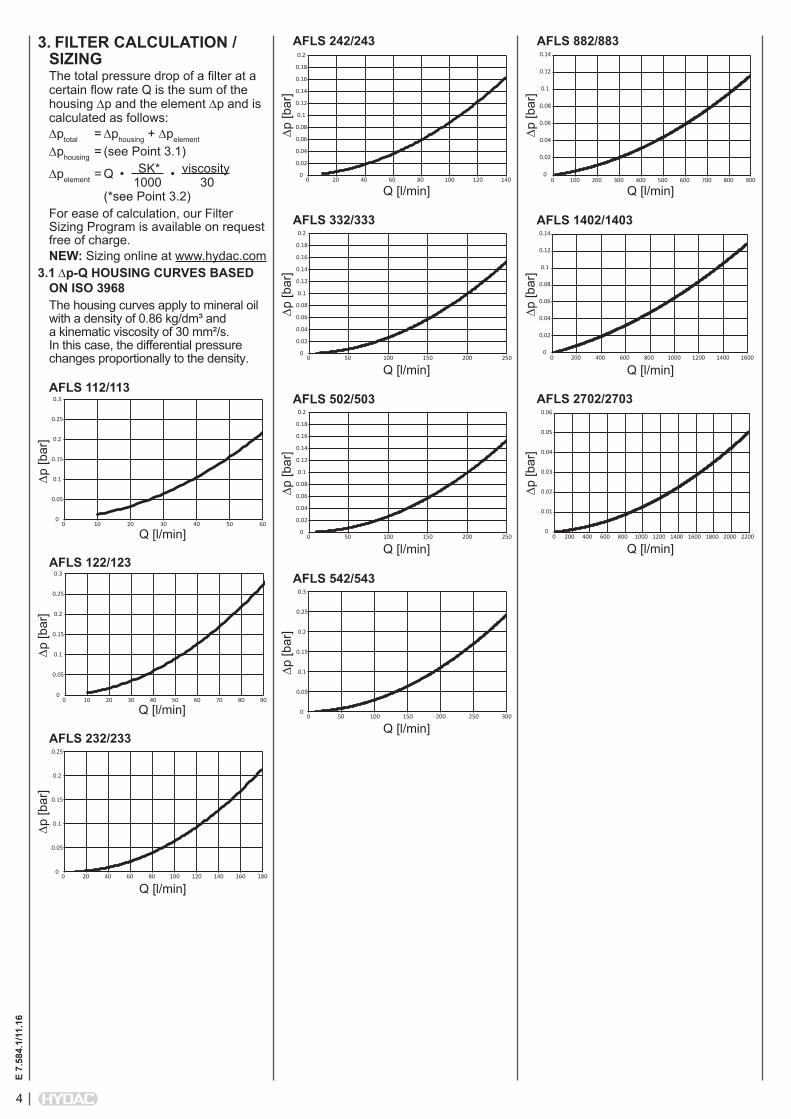
3. FILTER CALCULATION / SIZINGThe total pressure drop of a filter at a certain flow rate Q is the sum of the housing ∆p and the element ∆p and is calculated as follows:∆ptotal = ∆phousing + ∆pelement
∆phousing = (see Point 3.1)
∆pelement = Q • SK* • viscosity 1000 30 (*see Point 3.2)For ease of calculation, our Filter Sizing Program is available on request free of charge.NEW: Sizing online at www.hydac.com
3.1 ∆p-Q HOUSING CURVES BASED ON ISO 3968The housing curves apply to mineral oil with a density of 0.86 kg/dm³ and a kinematic viscosity of 30 mm²/s. In this case, the differential pressure changes proportionally to the density.
AFLS 112/113
∆p [b
ar]
Q [l/min]
AFLS 122/123
∆p [b
ar]
Q [l/min]
AFLS 232/233
∆p [b
ar]
Q [l/min]
AFLS 242/243
∆p [b
ar]
Q [l/min]
AFLS 332/333
∆p [b
ar]
Q [l/min]
AFLS 502/503
∆p [b
ar]
Q [l/min]
AFLS 542/543
∆p [b
ar]
Q [l/min]
0
0.01
0.02
0.03
0.04
0.05
0.06
0 200 400 600 800 1000 1200 1400 1600 1800 2000 2200
0
0.02
0.04
0.06
0.08
0.1
0.12
0.14
0 200 400 600 800 1000 1200 1400 1600
0
0.02
0.04
0.06
0.08
0.1
0.12
0.14
0 100 200 300 400 500 600 700 800 900
AFLS 882/883
∆p [b
ar]
Q [l/min]
AFLS 1402/1403
∆p [b
ar]
Q [l/min]
AFLS 2702/2703
∆p [b
ar]
Q [l/min]
5
E 7.
584.
1/11
.16
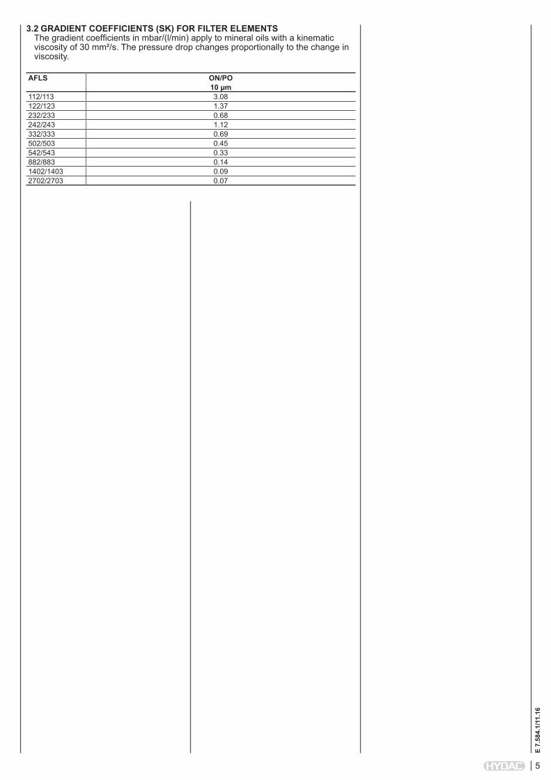
3.2 GRADIENT COEFFICIENTS (SK) FOR FILTER ELEMENTSThe gradient coefficients in mbar/(l/min) apply to mineral oils with a kinematic viscosity of 30 mm²/s. The pressure drop changes proportionally to the change in viscosity.
AFLS ON/PO10 µm
112/113 3.08122/123 1.37232/233 0.68242/243 1.12332/333 0.69502/503 0.45542/543 0.33882/883 0.141402/1403 0.092702/2703 0.07
6
E 7.
584.
1/11
.16
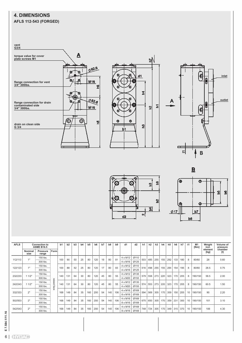
4. DIMENSIONSAFLS 112-543 (FORGED)
torque value for cover plate screws M1
vent G3/4
inlet
outlet
drain on clean side G 3/4
flange connection for vent 3/4" 300lbs.
flange connection for drain contaminated side 3/4" 300lbs.
AFLS Connection to ASME B16.5
b1 b2 b3 b4 b5 b6 b7 b8 b9 d1 d2 h1 h2 h3 h4 h5 h6 h7 t1 M1 [Nm]
Weight incl.
element [kg]
Volume of pressure chamber
[l]Nominal size
Pressure range
Form
112/113 1"150 lbs.
raised face
100 90 50 25 80 120 19 80 814 x M12 Ø110
503 485 255 155 292 133 180 8 80/60 28 0.60300 lbs. 4 x M16 Ø125
122/123 1"150 lbs.
100 88 52 25 80 120 17 80 834 x M12 Ø110
516 498 255 155 284 154 195 8 80/60 28.5 0.75300 lbs. 4 x M16 Ø125
232/233 1 1/2"150 lbs.
140 131 64 30 80 120 45 80 554 x M12 Ø135
579 558 273 220 323 170 205 8 190/150 58.5 2.00300 lbs. 4 x M20 Ø155
242/243 1 1/2"150 lbs.
140 131 64 30 80 120 45 80 554 x M12 Ø135
574 553 273 220 323 170 205 8 190/150 60.5 1.50300 lbs. 4 x M20 Ø155
332/333 2"150 lbs.
168 149 84 35 160 200 54 140 1064 x M16 Ø169
594 569 305 170 359 150 205 10 190/150 90 2.20300 lbs. 8 x M16 Ø169
502/503 2"150 lbs.
168 149 84 35 160 200 54 140 1064 x M16 Ø169
675 650 305 170 359 231 300 10 190/150 101 3.10300 lbs. 8 x M16 Ø169
542/543 2"150 lbs.
168 149 84 35 160 200 54 140 1064 x M16 Ø169
748 724 305 170 349 315 370 10 190/150 106 4.30300 lbs. 8 x M16 Ø169
7
E 7.
584.
1/11
.16
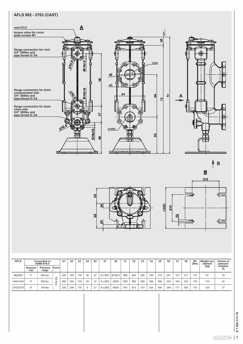
AFLS 882 - 2703 (CAST)
torque value for cover plate screws M1
vent G1/2
inlet
outlet
flange connection for drain clean side 3/4" 300lbs and pipe thread G 3/4
flange connection for vent 3/4" 300lbs and pipe thread G 3/4
flange connection for drain contaminated side 3/4" 300lbs and pipe thread G 3/4
AFLS Connection to ASME B16.5
b1 b2 b3 b4 b5 d1 d2 h1 h2 h3 h4 h5 h6 h7 h8 M1 [Nm]
Weight incl. element
[kg]
Volume of pressure chamber
[l]Nominal size
Pressure range
Form
882/883 3" 300 lbs. flat face
235 193 119 36 27 8 x Ø23 Ø168.3 908 844 285 330 515 241 127 411 110 81 16
1402/1403 4" 300 lbs. 268 224 133 53 31 8 x Ø23 Ø200 1067 982 290 385 650 226 160 532 170 110 24
2702/2703 6" 150 lbs. 325 239 175 5 21 8 x Ø23 Ø240 975 873 310 425 500 249 177 383 110 125 37
8
E 7.
584.
1/11
.16
NOTEThe information in this brochure relates to the operating conditions and applications described. For applications or operating conditions not described, please contact the relevant technical department. Subject to technical modifications.
HYDAC Filtertechnik GmbH Industriegebiet D-66280 Sulzbach/Saar Tel.: 0 68 97 / 509-01 Fax: 0 68 97 / 509-300 Internet: www.hydac.com E-Mail: [email protected]
NOTES