Inline Electric Motor Driven Compressor Library/Research/Oil-Gas/41643_DR...Inline Electric Motor...
54
© Copyright 2003 IEMDC IEMDC Inline Electric Motor Driven Compressor Inline Electric Motor Driven Compressor GMRC Conference GMRC Conference Salt Lake City, UT Salt Lake City, UT October 5, 2003 October 5, 2003
Transcript of Inline Electric Motor Driven Compressor Library/Research/Oil-Gas/41643_DR...Inline Electric Motor...

© Copyright 2003
IEMDCIEMDCInline Electric Motor Driven CompressorInline Electric Motor Driven Compressor
GMRC ConferenceGMRC ConferenceSalt Lake City, UTSalt Lake City, UT
October 5, 2003October 5, 2003

IEMDC - What is it?IEMDC - What is it?
� Inline Electric Motor Driven Compressor
� Inline - Pipe flange connections inline
� Electric Motor - Driven by high speed direct drive
induction motor that operates in process gas
environment and is powered by Variable
Frequency Drive
� Compressor - Single stage overhung compressor
stage directly mounted on motor shaft

IEMDC - IEMDC - ApplicationsApplications
� New pipelines
� Existing pipelines with low pressure ratios
� Pipelines near low cost power
� De-bottlenecking of plant process

IEMDC HighlightsIEMDC Highlights
� No building required
� Very quiet operation
� No on-site emissions
� Minimal piping
� Small site - Short construction time
� Below grade - lightning avoidance
� Battery of the Future?

PT
E.S.D
.
E.S.D
.
T T
INLINEDUCTED-FANCOMPRESSOR
FAN
Contr olBuilding
M CC/PLC
Lifting Eye
Stiffening Bar
Lifting Eye
Control Building
Anchor Block
TT
BY-PA
SS
LOA
DIN
G LIN
E
BLO
WO
FF
PTPT
PT
BLO
WO
FF
STA
TION
BY-PA
SS
STA
TION
GRADE
VER
TIC
AL SC
RU
BBE
R
FE
ESD vent
Concrete Vault
The Subterranean IEMDCThe Subterranean IEMDC• Out of sight, out of mind• Improved Security• “Good Neighbor Concept” - Low noise, Out of sight
Compliments of El Paso Natural Gas Co.

IEMDC - EconomicsIEMDC - Economics
� Reduction in piping $150K
� Building Reductions $100K
� Piping Pressure Loss $ 50K
� Emissions Fees $ 20K
� Higher Global Energy Efficiency
� Open cycle gas turbine efficiency = 35%
� Combined cycle power generation = 52%
• Includes gas and electrical transmission costs

IEMDC Status UpdateIEMDC Status Update
� Initial system cost estimates confirm commercial
viability of the IEMDC
� Design work confirms technical targets are
achievable
� Study commissioned to better define market
requirements and growth potential of the application.
Costs - Costs - Installation RangesInstallation Ranges
� Gas Turbines / Centrifugals
� $1300/bhp Industrial, 20 MW
� $1000/bhp Aeroderivative, 10 MW
� Reciprocating Engine / Compressor
� $1400/bhp Low Speed, 8 MW
� $750/bhp Medium Speed, 4 MW
� IEMDC
� $550/bhp 4 - 10 MW

Costs - Costs - Maintenance RangesMaintenance Ranges
� Gas Turbine / Centrifugal
� $19 Industrial Turbine, 20 MW
� $25 Aeroderivative, 10 MW
� Reciprocating Engine / Compressor
� $21 Low Speed, 8 MW
� $33 Medium Speed, 4 MW
� IEMDC and Conventional Motor
� $ 7 High Speed 4-10 MW

Speed Control with a VFDSpeed Control with a VFD
Reducing Speed to lowerflow results in higherefficiency and lower hp.
HP: 11,000 ⇒ 5,000Q: from 650 ⇒ 400 MM
• Fine Control
• 40% Savings overThrottling under similarconditions
Gas Compressor Performance Map
Operating Point
1 000
2 000
3 000
4 000
5 000
6 000
7 000
8 000
9 000
10 000
11 000
12 000
13 000
14 000
15 000
16 000
100 0 30 00 5000 7000 900 0 11000 13000
Inlet Vo lume ACFM
SurgeLine
Stone WallReg ion
SpeedLines(RPM)
Eff iciencyLines %
74.881.5
84.5
70
566 ,00 0
5 ,400
4 ,800
4 ,200
3 ,60 0
81.7

IEMDC - Making it happen...IEMDC - Making it happen...
� Advanced VFD Controller
� New Motor Designs
� Scaled Family of Frames
� Rugged Induction Motor
� Magnetic Bearings
� Standardization of Design

Magnetic BearingsMagnetic Bearings

IEMDC ConceptIEMDC Concept

� The IEMDC is a self contained module designed to be
installed directly into the pipeline
� Intrinsically safe because the motor is in an oxygen free
environment
� The IEMDC’s unique features are:
� Small construction footprint
� Minimal piping
� Low capital cost
� Power Generation Potential
IEMDC the Concept IEMDC the Concept
MainPipe

Overall Project ScopeOverall Project Scope
Phase 1 Design & Development - (In-Process)
Phase 2 Prototype Manufacture - (Proposed)
Phase 3 Demonstration Testing - (Proposed)
Phase 4 Fuel Cell Integration - (Proposed)

� A. Objectives
� The project objective is to design a direct-coupled,
seal-less, in-line motor driven compressor (IEMDC).
� Progress design to the point of starting detailed
manufacturing drawings
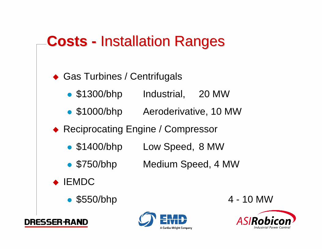
Statement of Project ObjectivesStatement of Project Objectives
� B. Scope of Work
� Development of the compressor aerodynamic
flowpath and pressure containment
� Development of the high-speed gas-cooled motor
� Development of the motor drive specification
� Definition and engineering of the compressor/motor
interfaces, including cable penetrations, gas-cooling
configuration, motor mounting, system rotordynamics
and system controls
Statement of Project ObjectivesStatement of Project Objectives
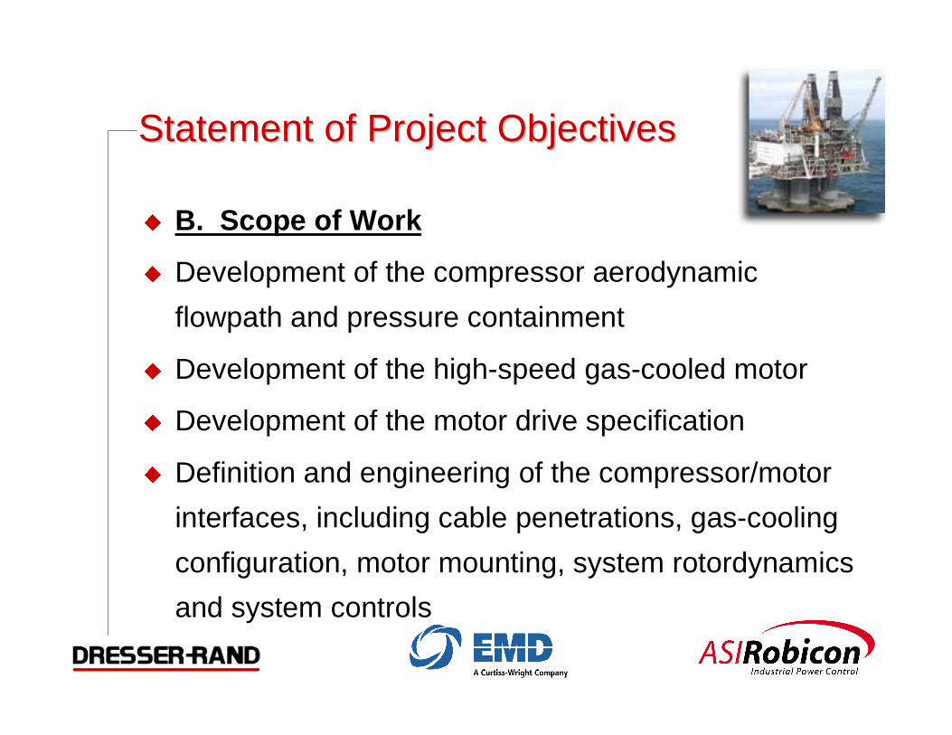
� Totally enclosed design.
� No shaft seals to the outside environment to create anemissionless design (no site leakage or emissions)
� Potential for Installation in an underground bunker
� Compressor direct coupled to the electric motor
� Eliminate oil and lubrication hazards
� Increased operating flexibility with variable speed motor
� Reduced installation costs over alternative systems
� Application of field proven technologies
� Capable of being directly installed in the pipeline
Project Technical RequirementsProject Technical Requirements
Important Design and Commercialization FactorsImportant Design and Commercialization Factors
� Aerodynamic design.� High level of efficiency
� Wide operating range
� Quiet operation
� Flexible configuration for performance optimization
� Proven aerodynamic performance predictability� Reliable, maintainable, and serviceable� Cost Effectiveness
� Low manufacturing cost� Low capital investment and installation cost� Low life cycle cost

IEMDC - Case DesignIEMDC - Case Design

� Motor Cooling Configuration
Status - ConfigurationStatus - Configuration
m sl•
m in•
m mc•
m process•
Qin
Motor
m process•
m sl•m mc
• +
R
Compressor
∆P
Tprocess
Pprocess
Tin
PinTdischarge
Pdischarge
Tmcin
Pmcin
Tmcout
Pmcout
Tslout
Pslout
∆PFlowcontroldevice

� Flowpath Surfaces
Status - Compressor FlowpathStatus - Compressor Flowpath
InletInlet
DischargeDischarge

Streamline of radial inletStreamline of radial inlet

� Volute design - evaluating several configurations
Status - CompressorStatus - Compressor
Scroll StyleScroll Style Scroll Style - Full TongueScroll Style - Full Tongue CollectorCollector
Static pressure on volute wall

High Speed Induction Motor DesignHigh Speed Induction Motor Design

Curtiss-Wright EMD - HistoryCurtiss-Wright EMD - History
� EMD formed in 1953 - a division of Westinghouse Electric Corp.
� Initial products related to Nuclear components
� Main coolant pumps for Navy shipboard reactors
� Pumps, valves, control rods for Westinghouse PWR plants

CurtissCurtiss Wright EMD – History (Contd.) Wright EMD – History (Contd.)
� Product mix expanded as Westinghouse Corp. restructured
� 1987 – Assigned responsibility for design and manufacture of Navy
Generators, originally done at W East Pittsburgh facility
� 1998 – Absorbed the Advanced Electro-mechanical systems group
from Westinghouse R&D
� A significant portion of Westinghouse rotating electric machine
capability and technology transferred to EMD
� EMD bought by Curtiss-Wright in 2001
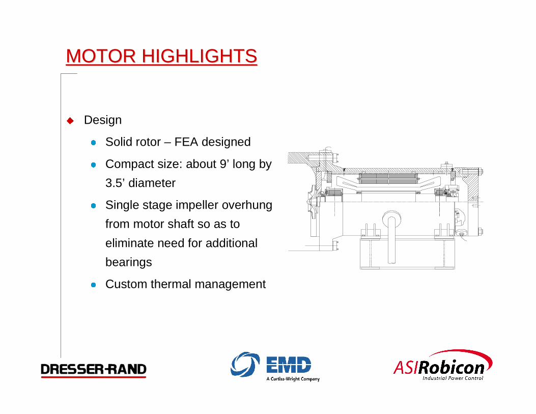
MOTOR HIGHLIGHTSMOTOR HIGHLIGHTS
� Design
� Solid rotor – FEA designed
� Compact size: about 9’ long by
3.5’ diameter
� Single stage impeller overhung
from motor shaft so as to
eliminate need for additional
bearings
� Custom thermal management

Motor Design Parameters
Parameter ValueMotor Type InductionOutput Power (hp/MW) 13,400/10L-L Voltage (Volts) 6,900Speed (rpm-sync.) 12,000Slip (%) 0.517Torque (ft-lb/N-m) 5895/7992Pole Number 2Frequency (Hertz) 200Cooling System Forced Ventilation w/ Methane GasBearings Active MagneticEfficiency (%) 94.9Power Factor 0.788Stator Core Outside Diamter (in./cm) 34.724/88.20
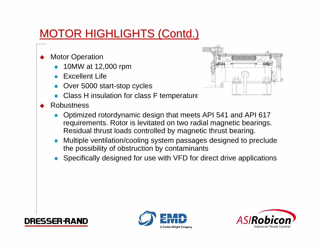
MOTOR HIGHLIGHTS (Contd.)MOTOR HIGHLIGHTS (Contd.)
� Motor Operation� 10MW at 12,000 rpm� Excellent Life� Over 5000 start-stop cycles� Class H insulation for class F temperatures
� Robustness� Optimized rotordynamic design that meets API 541 and API 617
requirements. Rotor is levitated on two radial magnetic bearings.Residual thrust loads controlled by magnetic thrust bearing.
� Multiple ventilation/cooling system passages designed to precludethe possibility of obstruction by contaminants
� Specifically designed for use with VFD for direct drive applications

MOTOR HIGHLIGHTS (Contd.)MOTOR HIGHLIGHTS (Contd.)
� 95 % motor efficiency� Reduced eddy current stator
core losses by using thinlaminations
� Minimized stator coil eddy lossby optimizing the strand sizes inboth the top and bottom coils
� Eliminated circulating currentsbetween coil strands throughstrand transposition
� Increased rotor-stator air gap tocontrol rotor surface losses
� Reduced bearing losses due touse of magnetic bearings

SummarySummary
� The design feasibility of a direct drive, robust, highly efficient, and high-speed motor has been demonstrated. The motor is powered by avariable speed drive. It is capable of delivering13,400 HP, at 12,000rpm, to the integral pipeline compressor that is mounted on the motorshaft.
� The motor is cooled by a portion of the high pressure discharge gasfrom the compressor, thereby eliminating the need for extra blower fansand heat exchangers.
� The motor-compressor system is levitated by active magnetic bearings,thus eliminating lubrication hazards. Because of the use of magneticbearings, the health of the pipeline compressor station can bemonitored from a remote location, providing economic benefits.

Multilevel Series PWMMultilevel Series PWMMedium VoltageMedium Voltage
Adjustable Speed DriveAdjustable Speed Drive
OverviewOverview

A Proven & Integrated ASD SystemA Proven & Integrated ASD System
� Isolation Transformer
� Harmonic Filtering
� Power Factor Correction
� Power Converter
� Motor Filter
� Included
� Inherent
� Inherent
� Included
� Inherent

POWER TOPOLOGYPOWER TOPOLOGY6600–7200 Volt Drive6600–7200 Volt Drive
16
AC Motor
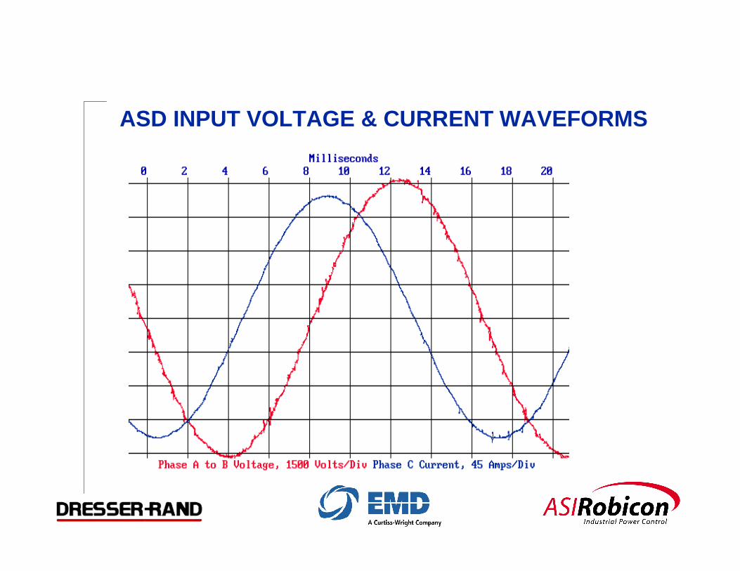
ASD INPUT VOLTAGE & CURRENT WAVEFORMS

PowerFactor
(%)
Percent Load
Total power factor includes distortion and displacement power factor.
Series PWM ASD
Measured Input Power Factor

ADDITION OF THREE CELL OUTPUTS TO CREATE PHASE VOLTAGE
CELL 1
CELL 2
CELL 3
COMPOSITE

ASD OUTPUT VOLTAGE & CURRENT WAVEFORMS

400 HP to 5,500 HP @ 2,300 VAC
400 HP to 8,000 HP @ 3,300 VAC
400 HP to 10,000 HP @ 4,160 VAC
1,000 HP to 60,000 HP @ 7,200 VAC
1,000 HP to 75,000 HP @ 13,800 VAC
400 HP to 8,500 HP Air Cooled
4,000 HP to 75,000 HP Liquid Cooled
Available Power Ratings / Output Voltage

Air Cooled Power Cell
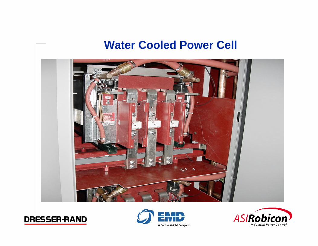
Water Cooled Power Cell
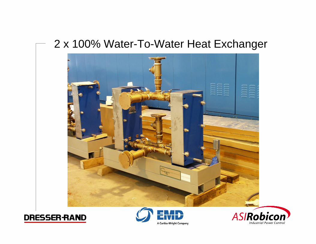
2 x 100% Water-To-Water Heat Exchanger

Water-To-Air Heat Exchanger

11,000 HP, 13.8/6.6 kV ASD

Integrated System Delivery
Multilevel S eries PWM AS DMultilevel S eries PWM AS DProven PerformanceProven Performance
� F irs t S ys tem Delivered - 1994
� Products in Use > 2000
� Products Ins talled per Year > 300
� High Capacity Products (5,000 HP +) > 1 per wk
� Current Product Generation - 3
� Output Voltages Available (2.3 to 13.8 kV)
� Largest Unit – 60,000 HP
� Critical T o Process Experience
� 5 Year Continuous S ervice with 4 - 9 Availability
� (ref. IE E E - PCIC-2001-09)

Other Related ExperienceOther Related Experience
� 12 Mag Bearing S upported Compressors Built
� Over 60 motor / compressor packages with VF D’s
� T he IEMDC is the marriage of these two proven technologies
IEMDC - Compressor SummaryIEMDC - Compressor Summary
� Proven Aerodynamic Design
� No Rotating Seals against Atmosphere
� Improved Reliability
� Reduced Maintenance
� Modular Construction for ease of Installation
� Future Uprate-ability

Faster Response & FlexibleFaster Response & Flexible
� Electric Drives can Start & Stop as needed
� Zero to full load in minutes
� Adjustable output
� Able to meet the needs of volatile power generation
applications
� VFD reduces transmission system impacts
� Clean and Green, no on-site emissions

Fuel Cell ImplicationsFuel Cell Implications
� Future on-site, high-efficiency generation
� Hydrogen extracted form methane to run fuel cell
� Assumes capital cost and technical issues will be
overcome
� Improved reliability
� Not subject to power outage
� Received proposal from SWRI for independent
project

IEMDC HighlightsIEMDC Highlights
� No building required
� Very quiet operation
� No site emissions
� Interchangeability
� No external cooling required
� Minimal piping
� Small site

IEMDC SummaryIEMDC Summary
� Lowest capital cost
� Lowest Operating Cost
� Minimal Environmental Impact
� Conserves Energy Resources
� Global energy efficiency 52% up from 35%
� Application is any clean, dry, oxygen free pipeline