Ingineria · Ingineria Automobilului C ould be the Automobile Engineering one of the open windows...
23
DISTRIBUTED WITH AUTOTEST MAGAZINE Vol. 7, no. 4 (29) / 2013 SIAR IS AFFILIATED TO INTERNATIONAL FEDERATION OF AUTOMOTIVE ENGINEERING SOCIETIES EUROPEAN AUTOMOBILE ENGINEERS COOPERATION Ingineria Automobilului Society of Automotive Engineers of Romania Romanian Automobile Register l Experimental Study of the Energy Efficiency of Cars l Simulations of a Compression Ignition Engine Engine Powered by Different Fuel Blends when Changing Injection Parameters International Congress of the Society of Automotive Engineers of Romania Grand Hamster E4WD DACIA Hybrid Concept Car
Transcript of Ingineria · Ingineria Automobilului C ould be the Automobile Engineering one of the open windows...

DISTR IBU TED WITH AU TOTEST M AG A ZINEVol. 7, no. 4 (29) / 2013
SIAR IS AFFILIATED TO
INTERNATIONALFEDERATION OFAUTOMOTIVEENGINEERINGSOCIETIES
EUROPEANAUTOMOBILEENGINEERSCOOPERATION
IngineriaAutomobilului Society of
AutomotiveEngineers
of Romania
RomanianAutomobileRegister
l Experimental Study of the Energy Efficiency of Cars l Simulations of a Compression Ignition Engine Engine Powered by Different Fuel Blends when Changing Injection Parameters
International Congress of the Societyof Automotive Engineers of Romania
Grand Hamster E4WDDACIA Hybrid Concept Car

ALTERNATIVE CARS IN THE 21ST CENTURY. A NEW PERSONAL TRANSPORTATION PARADIGM. SECOND EDITION Author: Robert Q. Riley
Author: Robert Q. RileyPublisher : SAE InternationalPublished: 2004ISBN: 0-7680-0874-3
Contents:• Personal Mobility in Crisis• Personal Mobility Vehicles for the 21st century• The Technology of Fuel Economy• Alternative Fuels• Electric and Hybrid Vehicles• Three-Wheel Cars with Tilting Three-Wheel Vehicle Information• Safety and Low-Mass Vehicles• Intelligent Transportation Systems• Alternative Cars in Europe
AUTOMOTIVE TRANSMISSIONS FUNDAMENTALS. SELECTION DESIGN AND APPLICATION.SECOND EDITIONAuthors: Harald Naunheimer, Bernd Bertsche, Joachim Ryborz, Wolfgang Novak
Publisher : Springer-Verlag Berlin HeidelbergPublished: 2004ISBN: 978-3-642-16213-8
This book gives a full account of the development process for automotive transmissions.Main topics:• Overview of the traffic-vehicle-transmission system• Mediating the power flow in vehicles• Selecting the ratios• Vehicle transmission systems, basic design principles• Typical designs of vehicle transmissions• Layout and design of important components, e.g. gearshifting mechanisms, moving-off elements, pumps, retarders• Transmission control units• Product development process• Manufacturing technology of vehicle transmissions• Reliability and testingThe book covers manual, automated manual and automatic transmissions as well as continuously variable transmissions and hybrid drives for passenger cars and commercial vehicles. Furthermore, final drives, power take-offs and transfer gearboxes for 4-WD-vehicles are considered.

3
Ingineria Automobilului
Could be the Automobile Engineering one of the open windows for the Romanian Au-tomotive Engineering scientific research?
A sharper glance slices like a diamond shatters of the inert, dusty window of the Romanian industry and reveals a rather discouraging picture.At the very foundation of the scientific research, no matter the field, resides the specific social de-mand to innovating, up-to-dating, competing and
performing. But for years, the Romanian Automotive Industry focuses almost ex-clusively on passenger cars. There is a good reason for it: former famous factories (i.e. ROMAN, Tractorul, ARO) had diminished or ceased their activities; next to them, powerful research and design institutions were developing their activities.Within this context, from the heights built-up by media, the Automobile Engi-neering looks downwards to its “poorer”, less spotlighted relatives. The scien-tific research developed by the decreased number of the university professors and researcher that could provide some innovation for the truck, tractors, bus-es and special vehicles industry seems to be pointless. As a result, the interest in developing / innovating / manufacturing this kind of vehicles or components for these vehicles continuously decreased. Nevertheless, I believe that the sci-entific research within the Automotive Engineering field should pay attention to the whole lifecycle (designing, manufacturing, using, maintaining, decom-missioning and disassembling) to all the automotive categories.I led the Military Vehicles and Transportation Department of the Mili-tary Technical Academy more than 10 years. During all this time I have developed, along with my colleagues, a new concept, which we called mobile terrestrial bearing platform for technical systems (PMT-PST). Ac-cording to a systemic approach, it consists of a basic module, wheeled or tracked propelled, on which different systems were mounted: weapon
systems (cannons, mortars, rocket launchers etc.), command and control systems, radar installations, day-and-night surveillance systems, medical evacuation systems (MEDEVAC), recovery and technical maintenance systems, communication systems, assault vehicles and so on. These ve-hicles became, consequently, combat vehicles, mobile command nodes, surveillance stations or different special vehicles. Moreover, they could be armored or not and they could be fitted with personnel or goods transpor-tation modules, able to perform within a modern warfare environment.The activity of research-development-testing consisted of both the classic approach of the wheeled or tracked vehicles’ designing, manufacturing and maintenance, and the specific elements of the particular type of in-stalled equipment (such as the weapon system’s stabilization, protection against enemy fire, mobility and progression capacity in difficult condi-tions, unique fuel refueling, vehicle’s buoyancy, etc.).The good results achieved in time were due, among others, to the excellent co-operation with the remaining specialist of the former specialized indus-trial branches as well as with the other Technical Universities in Romania.The previous given examples testify the fact that by reuniting the technical capacities and the human resources, the Romanian research in this branch of activity could significantly get involved in developing and innovating various special vehicles or their components.The existence of high level competencies in this filed within the Automotive Departments of various Universities provides an important, but not enough known and used resource by the Romanian specialized companies.So, who takes the first step?
Professor Minu MTREA, Eng., PhDSecretary General of SIAR
Former Head of the Military Vehicles and Transportation Department of the Military Technical Academy
Summary „Ingineria Automobilului“ No. 29 (vol. 7, no. 4)
Automobile Engineering versus Automotive Engineering Ingineria Automobilelor versus Ingineria Autovehiculelor
3 Automobile Engineering versus Automotive Engineer
Ingineria Automobilelor versus Ingineria Autovehiculelor
5 International Congress of the Society of Automotive
Engineers of Romania – SIAR
Automotive Motor Mobility Ambient – AMMA 2013
Congresul Internaţional al Societăţii Inginerilor de Automobile
din România – SIAR
8 Experimental Study of the Energy Efficiency of Cars
Studiul experimental al eficienţei energetice
a automobilelor
12 Simulations of a Compression Ignition Engine Powered
by Different Fuel Blends when Changing Injection Parameters
Simularea funcţionării unui motor cu aprindere
prin comprimare alimentat cu biocombustibili
în cazul modificării parametrilor de injecţie
15 High Order Spectral Analysis of a Measured Automotive Parameter
Analiza spectrală de ordin superior a semnalului unei mărimi
mecanice măsurate în transmisia unui automobil. Modele
matematice obţinute prin identificare
20 University Research: Symposium „EV&HV 2013 – Innovation in
Electric and Hybrid Mobility” Automotive Engineering
Research Centre, University of Piteşti. 1 november 2013

4
Ingineria Automobilului
ROMANIAN AUTOMOBILE
REGISTER
General ManagerGeorge-Adrian DINCĂ
Technical ManagerFlavius CÂMPEANU
AUTO TEST
Chief EditorLorena BUHNICI
EditorsRadu BUHĂNIŢĂ
Emilia PETRE
Contact:Calea Griviţei 391 A,
sector 1, cod poştal 010719, Bucureşti, România
Tel/Fax: 021/202.70.17E-mail: [email protected]
www.rarom.rowww.autotestmagazin.ro
SIAR
ContactFaculty of Transport
University POLITEHNICAof Bucharest
Splaiul Independenţei 313Room JC 005
Cod poştal 060032, sector 6Bucureşti, România
Tel/Fax: 021/316.96.08E-mail: [email protected]
www.ingineria-automobilului.rowww.siar.ro
PRINTINGART GROUP INT SRL
Str. Vulturilor 12-14, sector 3Bucureşti
Full or partial copying of text and pictures can be done only with Auto Test Magazine approval, of the Romanian Automobile
Register and of SIAR
SOCIETY OF AUTOMOTIVE ENGINEERS OF ROMANIAPresident: Conf. dr. ing. Adrian CLENCI, University of Piteşti
Honorary President: Prof. dr. ing. Eugen NEGRUŞ, University Politehnica of BucharestVice-president: Prof. dr. ing. Cristian ANDREESCU, University Politehnica of Bucharest
Vice-president: Prof. dr. ing. Nicolae BURNETE, Technical University of Cluj-NapocaVice-president: Prof. dr. ing. Anghel CHIRU, University „Transilvania” of Braşov
Vice-president: Prof. dr. ing. Victor OŢĂT, University of CraiovaVice-president: Prof. dr. ing. Ioan TABACU, University of Piteşti
General Secretary of SIAR: Prof. dr. ing. Minu MITREA, Military Technical Academy of Bucharest
Editor in chief: Prof. Dr. -Ing. habil. Prof. E. h. Dr. h.c. Cornel STAN Executive editor: Prof. dr. ing. Mircea OPREAN, University Politehnica of Bucharest
Deputy chief editor:Prof. dr. ing. Gheorghe-Alexandru RADU, University „Transilvania” of Braşov
Prof. dr. ing. Ion COPAE, Military Technical Academy of BucharestConf. dr. ing. Ştefan TABACU, University of Piteşti
Redactors:Conf. dr. ing. Adrian SACHELARIE, University „Gheorghe Asachi” of Iaşi
Conf. dr. ing. Ilie DUMITRU, University of CraiovaS.l. dr. ing. Cristian COLDEA, Technical University of Cluj-Napoca
S.l. dr. ing. Marius BĂŢĂUŞ, University Politehnica of BucharestS.l. dr. ing. Gheorghe DRAGOMIR, University of Oradea
Editorial secretary: Prof. dr. ing. Minu MITREA, General Secretary of SIAR
AVL List Romania – Werner MOSERRomanian Automobile Register – RAR – George-Adrian DINCĂ
The National Union of Road Hauliers from Romania – UNTRR – Florian MIHUŢ
EDITORIAL BOARD
HONORARY COMMITTEE OF SIAR
SCIENTIFIC AND ADVISORY EDITORIAL BOARDProf. Dennis ASSANIS
University of Michigan, Michigan, USA
Prof. Rodica A. BĂRĂNESCUUniversity of Iilinois, Chicago College of
Engineering, USA
Prof. Nicolae BURNETETechnical University of Cluj-Napoca, Romania
Prof. Giovanni CIPOLLAPolitecnico di Torino, Italy
Dr. Felice E. CORCIONEEngines Institute, Naples, Italy
Prof. Georges DESCOMBESConservatoire National des Arts et Metiers de Paris,
France
Prof. Cedomir DUBOKAUniversity of Belgrade, Serbia
Prof. Pedro ESTEBANInstitute for Applied Automotive Research,
Tarragona, Spain
Prof. Radu GAIGINSCHITechnical University „Gheorghe Asachi” of Iaşi,
Romania
Prof. Berthold GRÜNWALDTechnical University of Darmstadt, Germany
Eng. Eduard GOLOVATAI-SCHMIDTSchaeffler AG & Co. KG Herzogenaurach, Germany
Prof. Peter KUCHARUniversity for Applied Sciences, Konstanz, Germany
Prof. Mircea OPREANUniversity Politehnica of Bucharest, Romania
Prof. Nicolae V. ORLANDEARetired Professor, University of Michigan Ann Arbor, USA
Prof. Victor OŢĂTUniversity of Craiova, Romania
Prof. Pierre PODEVINConservatoire National des Arts et Metiers de Paris, France
Prof. Andreas SEELIGERInstitute of Mining and Metallurgical Machine, Engineering, Aachen, Germany
Prof. Ulrich SPICHERKalrsuhe University, Karlsruhe, Germany
Prof. Cornel STANWest Saxon University of Zwickau, Germany
Prof. Dinu TARAZAWayne State University, USA
Automotive Engineering: print edition publication, 2006 (ISSN 1842-4074), electronic edition, 2007 (ISSN 2284-5690).New Series of the Journal of Automotive Engineers (RIA), printed in 1992-2000

5
Ingineria Automobilului
During 17 to 19 October 2013, Alma Mater Napo-censis, Technical Univer-
sity of Cluj-Napoca organized “Au-tomotive Motor Mobility Ambient – AMMA 2013” - International Congress of Society of Automotive Engineers of Romania – SIAR, un-der the high patronage of FISITA (International Federation of Auto-motive Engineering Societies), ac-companied by a suite of events that focused the attention of Romanian and foreign specialists in the field of automotive engineering and road transport.The host of SIAR Congress was for the third time Automotive and Transport Department of the Tech-nical University of Cluj-Napoca, one of the poles of excellence in ap-plied and fundamental research in the automotive industry, with wide recognition nationally and interna-tionally.All events centered around AMMA International Congress in 2013 made the city of Cluj-Napoca to become, for a few days, an inter-national center for automotive en-gineering, providing opportunities for useful contacts and information to date on the major issues of vehi-cle development and environment.Mobility of ideas, goods and peo-ple characterize contemporary so-ciety, one of the main elements of the future development of human society and the automotive indus-
try is an important factor in this direction. Aware of the importance of addressing current and future issues that face the automotive en-gineering, the participants in the International Congress AMMA 2013 and aims to address them, discuss and formulate solutions in an appropriate scientific frame-work, confirmed the presence of a number of specialists academic, economic and social, both in the country and abroad.Departments of interest AMMA International Congress 2013 were directly related to scientific re-search in the field of automotive engineering, ideas, inventions and new and emerging technologies related to the following topics: hy-brid and electric vehicles, advanced propulsion systems, vehicle design, advanced engineering and com-puter simulation, road safety and traffic control, materials and inno-vative technologies, green vehicles and pollution caused by internal combustion engines.The Congress provided an oppor-tunity for all professionals in the automotive and environmental en-
gineering (researchers, designers, users and producers) to achieve a fruitful exchange of views and to contribute to the growth of educa-tion in these areas.More than 275 participants at the congress had the opportunity to be actively involved in the scientific papers presented in plenary and in sections, workshops, exhibitions, leisure.AMMA 2013 opening of the Congress brought in front of par-ticipants: Günter Hohl - FISITA representative, former President of the EAEC (European Coopera-
tion Automotive Engineers) Gigel Paraschiv - Secretary of State, Min-istry of National Education, Aurel Vlaicu - Rector of the Technical University of Cluj-Napoca, Ho-ria Dorin Uioreanu - Cluj County Council President Mihnea Ioraş - Subprefect of Cluj Adrian Clenci - President SIAR, Gheorghe-Alex-andru Radu - Academy of Techni-cal Sciences of Romania, Stefan Kanya - regional Director Europe - AVL List GmbH.After the official opening of the congress plenary session presenta-tion took place.
AUTOMOTIVE MOTOR MOBILITY AMBIENT – AMMA 2013International Congress of the Society of Automotive Engineers of Romania – SIARCongresul Internaţional al Societăţii Inginerilor de Automobile din România – SIAR
Professor Eng. Nicolae BURNETEPh. D., Congress PresidentTechnical University of [email protected]
The opening festivity
Mr. Günter Hohl – presentation of the paper-work

6
Ingineria Automobilului
The first paper, presented in plenary by Günter Hohl, entitled „FISITA and the Automotive World“ start-ed with an overview of FISITA, putting into evidence the fact that it represents more than 170,000 engineers worldwide, having an important role innovation in the automotive engineering, develop-ment of various industry standards and the scientific support organiza-tion. SIAR members in that SIAR is part of FISITA participate in the global effort to develop engineer-ing and road transport vehicles. FISITA and EAEC Congresses are opportunities to show unity and efforts of Automotive Engineers. It was further shown an evolution of vehicles, both international inven-tors and Romanian, remembering the Belu Barbu, Dimitrie Leonida, Aurel Persu and others, along with changes in automotive production in Romania.It was stressed the important role that the car industry has both the European economy and the world is said that this is the „engine of Europe „. Also mentioned the fact that although the number of com-panies producing vehicles fell from 36 in 1970 to 15 in 2000 , increased diversity of models (sedan, sports car, SUV ... the pick -up, MPV, hatchback, SW, coupe, roadster) from 3-15, then recalled the target in terms of environmental protec-tion, namely a better air quality and reduce vehicle noise. Automotive future involving new technologies: environmentally friendly electric cars and interconnected and au-tonomous vehicles. In conclusion, cars, buses and trucks will remain the main option for the transport of people and goods, will increase environmental protection require-ments, and educating the public on the importance of environmentally friendly transport will increase.A second paper, presented in Par-liament by George Druţă adviser ACAROM, entitled „The auto industry in Romania, develop-
ments and prospects for devel-opment” said the comprehensive development of the automotive
industry is shaken marked „migra-tions” Inter-zonal and hierarchy changes. He was presented the evo-
lution of automobile production worldwide, continuing with the main pillars of the automotive in-dustry in Romania: Dacia - Renault and Ford Romania. After describ-ing the evolution of sales of new motor vehicles presented exports of cars and vans and emphasized that it supports both domestic production and the entire national economy. There was an overview of the major automotive suppli-ers in Romania, emphasizing that the top 20 suppliers/manufactur-ers globally, 13 produce auto parts in Romania. Components sector remains attractive and relatively competitive in the Central -East-ern Europe. It highlighted the role ACAROM programs to increase competitiveness and opportunities of a regional cluster, the work end-ing by presenting perspectives of automotive industry in ACAROM vision.From AVL GmbH, Stefan Kania presented „The connected power-train TM”. After stressing that AVL is the largest development, simu-lation and testing technology of powetrain in the world (with 6,200 employees and a 12.5% invest-ment in research and innovation) were presented aims to develop transmission and new concepts in automotive engineering. Based on a hybrid vehicle demonstration in 2004, with emissions of only 90-98 g/km of CO, with a 1.2l engine with 3 cylinders, developing 60 kW, since 2006 an optimized tur-bo-hybrid has been presented, also the „connected vehicle” equipped with the system of driving direc-tion keeper, „smart cruise control” and the concept of CONNECTED POWERTRAIN TM. Also was pre-sented control architecture and changes to this system and AVL system RANGE EXTENDER.Cristian Nevzoreanu, Public Affairs Director of Renault Technologie Roumanie, presented the paper” ROMANIA – A Competences Center for Renault”.
Evolution of the autovehicle global production
Industrial orizontal areas with development induced by the evolution of the romanian automobile industry
The opening of the exhibition
7
Ingineria Automobilului
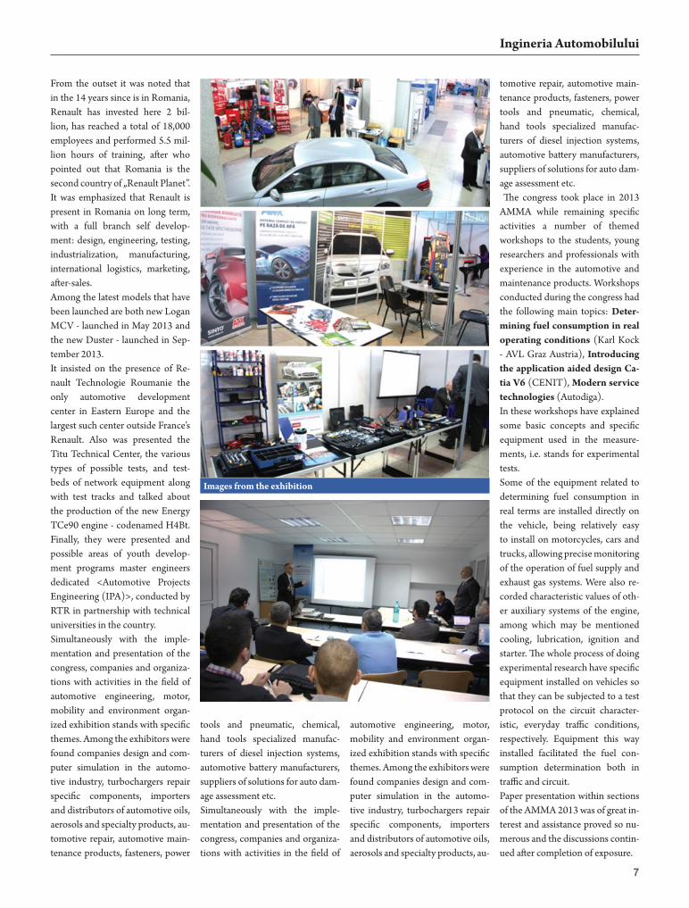
From the outset it was noted that in the 14 years since is in Romania, Renault has invested here 2 bil-lion, has reached a total of 18,000 employees and performed 5.5 mil-lion hours of training, after who pointed out that Romania is the second country of „Renault Planet”. It was emphasized that Renault is present in Romania on long term, with a full branch self develop-ment: design, engineering, testing, industrialization, manufacturing, international logistics, marketing, after-sales.Among the latest models that have been launched are both new Logan MCV - launched in May 2013 and the new Duster - launched in Sep-tember 2013.It insisted on the presence of Re-nault Technologie Roumanie the only automotive development center in Eastern Europe and the largest such center outside France’s Renault. Also was presented the Titu Technical Center, the various types of possible tests, and test-beds of network equipment along with test tracks and talked about the production of the new Energy TCe90 engine - codenamed H4Bt. Finally, they were presented and possible areas of youth develop-ment programs master engineers dedicated <Automotive Projects Engineering (IPA)>, conducted by RTR in partnership with technical universities in the country.Simultaneously with the imple-mentation and presentation of the congress, companies and organiza-tions with activities in the field of automotive engineering, motor, mobility and environment organ-ized exhibition stands with specific themes. Among the exhibitors were found companies design and com-puter simulation in the automo-tive industry, turbochargers repair specific components, importers and distributors of automotive oils, aerosols and specialty products, au-tomotive repair, automotive main-tenance products, fasteners, power
tools and pneumatic, chemical, hand tools specialized manufac-turers of diesel injection systems, automotive battery manufacturers, suppliers of solutions for auto dam-age assessment etc.Simultaneously with the imple-mentation and presentation of the congress, companies and organiza-tions with activities in the field of
automotive engineering, motor, mobility and environment organ-ized exhibition stands with specific themes. Among the exhibitors were found companies design and com-puter simulation in the automo-tive industry, turbochargers repair specific components, importers and distributors of automotive oils, aerosols and specialty products, au-
tomotive repair, automotive main-tenance products, fasteners, power tools and pneumatic, chemical, hand tools specialized manufac-turers of diesel injection systems, automotive battery manufacturers, suppliers of solutions for auto dam-age assessment etc. The congress took place in 2013 AMMA while remaining specific activities a number of themed workshops to the students, young researchers and professionals with experience in the automotive and maintenance products. Workshops conducted during the congress had the following main topics: Deter-mining fuel consumption in real operating conditions (Karl Kock - AVL Graz Austria), Introducing the application aided design Ca-tia V6 (CENIT), Modern service technologies (Autodiga).In these workshops have explained some basic concepts and specific equipment used in the measure-ments, i.e. stands for experimental tests.Some of the equipment related to determining fuel consumption in real terms are installed directly on the vehicle, being relatively easy to install on motorcycles, cars and trucks, allowing precise monitoring of the operation of fuel supply and exhaust gas systems. Were also re-corded characteristic values of oth-er auxiliary systems of the engine, among which may be mentioned cooling, lubrication, ignition and starter. The whole process of doing experimental research have specific equipment installed on vehicles so that they can be subjected to a test protocol on the circuit character-istic, everyday traffic conditions, respectively. Equipment this way installed facilitated the fuel con-sumption determination both in traffic and circuit.Paper presentation within sections of the AMMA 2013 was of great in-terest and assistance proved so nu-merous and the discussions contin-ued after completion of exposure.
Images from the exhibition

8
Ingineria Automobilului
8
Ingineria Automobilului
ABSTRACTThe article presents the problem of establishing energy efficiency of cars, which considers both power performance and fuel consumption of their. Study is based on experi-mental data obtained from tests of cars equipped with on-board com-puter and embedded transducers.
Nowadays, the car is one of repre-sentative mechatronic products, an excellent example of integrating software of mechanical, electronic and informatics components. From the beginning until today, the car revolutionized transportation and it concentrated the most significant engineering effort to improve con-tinuously its performance.Among the main requirements, which are imposed on cars, are also those relating to their dynamics and fuel saving; usually, these two requirements can not be satisfied simultaneously to the desired max-imum level. In the specialty litera-ture, the study of dynamics and fuel saving is performed separately from each other, without resorting to the
interconnections between them.In the classic sense of the literature, the references of dynamics belong only start-up, typically the accelera-tor start-up time and space. Broadly speaking, dynamics refers to the whole movement, it only for the fact that the dynamics represents any variation in time.Similarly, in the classic sense of the literature, the references of fuel sav-ing refer only to fuel consumption, expressed in various forms. Broadly speaking, we should question and about other issues, for example those relating to the use of fuel en-ergy input for the engine efficiency, for propulsion etc.Lately, it puts more and more the problem that refers at increasing energy efficiency of a car, which aims dynamics and fuel saving interrelated each other [1, 2, 3]. In other words, it does not want a
high dynamic energy without con-sider the effort to get it; for this rea-son, the main efforts are directed towards improving economic effi-ciency more than towards improv-ing dynamics, obviously because of the limited oil resources. This effort is understandable, given that the car is a means of transport with very low efficiency, wasting a lot of energy introduced with the fuel.Efforts aimed at improving energy efficiency targets simultaneously fuel saving and dynamics, but in one sense: lower fuel consumption by affecting dynamics limits im-posed. In this regard, recent stud-ies and research in this area oper-ate with the concept called ERFC (Emphasis on Reducing Fuel Consumption) with quantitative expression that signifies what per-centage of dynamic performance is sacrificed for fuel economy [1].
ERFC criteria value is determined by the relationship:
ERFC c r
c p
C C
C C
−=
− (1)
where: Cc - current fuel consump-tion, Cr – achieved fuel consump-tion, Cp - potential fuel consump-tion (possibly reduced).For example, if we want to reduce fuel consumption in 2035 to 62.5% of the current value by sacrificing dynamic performance by 50%, of equation (1) is made of a relatively fuel consumption:
ERFC( ) 1 0, 5(1 0, 625) 0,8125r c c pC C C C= − − = − − =
(2)
ERFC( ) 1 0, 5(1 0, 625) 0,8125r c c pC C C C= − − = − − =
as can be noticed in figure 1 [1].As stated, the size ERFC is actu-ally a criterion of energy efficiency
Experimental Study of the Energy Efficiency of CarsStudiul experimental al eficienţei energetice a automobilelor
Eng. Mihail [email protected]
Eng.George ENEemail: [email protected]
Eng. Marian-Eduard RĂDULESCUemail: [email protected]
Professor Eng. Ion COPAE, Ph.D.Military Technical Academy of Bucharest, email: [email protected]
Fig.1. Consumption calculation by implementing criteria ERFC

9
Ingineria Automobilului
because fuel economy is based pri-marily on reducing the dynamics of the car. In order not to affect drastically the dynamics, the building companies will have to improve manufacturing technologies and to adopt new con-structive measures. The experts in the field believe that it will have a big impact the weight of the car, mean-ing significantly reducing it. For example, if it aims to achieve ERFC value of 50% (Figure 1), the current car must weigh with 10% less.
As a consequence to the above, in Figure 2 presents the forecast for the year 2035 on the dynamics and fuel saving of a middle class car based on the degree of imple-mentation ERFC compared to the current situation was targeted for dynamic time starting from zero speed to 100 km/h, and for eco-nomical fuel consumption per 100 km traveled by car [1].Figure 2 shows that in 2035 the dynamics decreases and fuel sav-ing increases with increasing value
ERFC. If it will be not implement-ed ERFC 2035, the fuel saving of the current remains the same and the dynamics will be improved mainly due to decreasing vehicle mass.In order to emphasize energy ef-ficiency, some experimental re-searches were carried out with a Skoda Octavia fitted with fuel injection engine and with power plant liquefied petroleum gas (LPG), which covered most func-tional regimes encountered in nor-
mal operation with a movement with a normal driving style. The analyze of energy efficiency of the car was based on experimental data by defining and setting the criteria for assessing the energy efficiency by comparing it to the two fuels us-ing the concept of equivalent ener-gy efficiency; these criteria should evaluate the use of quantitative energy introduced with the fuel, which are the consequences of this use in terms of energetic plan and which are the factors that influence
Fig.2. Forecast for 2035 to dynamic and fuel saving
Fig.3. Criterion for energy efficiency kc for operation with gasoline

10
Ingineria Automobilului
the most energy efficiency.The first criterion for calculation the energy efficiency is the ratio of the kinetic energy of the car and the energy introduced with the fuel [3]:100cin
c
i
Wk
W= ⋅
(3)
where the two energies are deter-mined by the following relations:
2
2
acin
m vW =
(4)
respectively:h i p
i
C Q SW
V=
(5)
In these expressions were noted: ma – vehicle weight, Ch - hourly fuel consumption of the engine, Qi - lower heating value of the fuel, Sp - space map, v [m/s], V [km/h] - vehicle speed.Figure 3a shows the results which were obtained for 50 tests when engine is running with gasoline. As will be noted from Figure 3c, for these all tests, 34.86% of the energy input with the fuel is actually used for driving the vehicle. The values of this ratio vary in the range 25.33 ÷ 40.73%.Since equation (3) calls from the kinetic energy of the car, which is the effective displacement energy consumed and the energy intro-duced with the fuel that is the most
Fig.4. Mean of tests energy efficiency criterion kc for operation with LPG
Fig.5. Fuel consumption per 100 kilometers on petrol and LPG operation
Fig.6. Average values/tests of energy efficiency criterion kws

11
Ingineria Automobilului
important criterion in assessing the energy efficiency; this criterion has a dynamic component Wcin and a fuel saving component Wi.If it uses fuel consumption per 100 km, C100, then the equation (5) be-comes:
100
100
i p
i
Q S CW
ρ=
(6)
where ρ is fuel density.The equation (6) is useful when it is desired that in the study of en-ergy efficiency to consider the fuel price P [lei/liter], not only the dy-namic and fuel saving elements. As noted, the equation (6) shows two sizes which depend on fuel type, ρ and Qi , both lower for LPG.Figure 4 presents the results which were obtained for 50 tests when the engine is running on LPG. As will be noted from Figure 4a, in all of these samples 30.15% of the energy input to the fuel is actually used for move the vehicle, the value is of 4.71% less than that of the value when it is used the gasoline. Sample values of this ratio vary in the range 19.28 ÷ 37.87%.Taking into account the price P, density ρ and lower calorific power Qi for these two fuels, then it gets an average equivalent relation in the case of LPG, as shown in Fig. 4b and calculated with the formula:
g igbce c
g b ib
QPk k
P Q
ρ=
ρ
(7)
As shown, this time the car equiva-lent energy efficiency increases, meaning that the average value of all tests increased to 44.13%, ex-ceeding the 9.27% amount of gaso-line (34.86%).In equation (7) the index „b“ refers at gasoline and subscript „g“ refers at liquefied petroleum gas. This equation shows that LPG is favored if we speak about price (Pb = 6.01 lei/liter; Pg = 2.85 lei/liter - on ex-periments) but it is disfavored if we speak about density (rb = 0.74 kg/liter; rg = 0.54 kg/liter) and lower calorific value (Qib = 47300 kJ/kg; Qig = 45000 kJ/kg): as a result, the first factor equivalent ratio in-creases the ratio and the other two decrease it.In this regard, it should be noted that if there is a LPG equivalent consumption, so consumption compared to gasoline. Equivalent fuel consumption per 100 km is calculated from an expression of type (7):
100 100
g b ibe
b g ig
P QC C
P Q
ρ=
ρ
(8)
which shows that the price of gas is a factor that reduces the equivalent consumption, and the density and the lower calorific value increases
it. Under these conditions, fig.5a shows average values of equivalent consumption of LPG/tests and, compared, in fig.5b gasoline con-sumption per 100 km driven.As noted in figure 5a, equivalent to LPG consumption for the all tests is 7.7 litres/100 km, compared to the value of consumption of 11.3 litres/100km during the experi-ments. In addition, it is noted that the two graphs equivalent to LPG consumption value is close to that of gasoline consumption (7.4 li-tres/100 km), is only 4.1% higher.The second criterion for calcula-tion of energy efficiency is the ratio of energy introduced with fuel and space traveled by car:
iws
p
Wk
S=
(9)
the numerator resorting to the fuel saving, and the denominator the dynamics.Figure 6 presents kws ratio values for both fuels, from which it appears that in the case of LPG to scroll through one kilometer is required a fuel energy of 2.04 times higher than gasoline for the all tests, in average. If in this case it is defined a ratio kwse equivalent with gasoline (Figure 6b), the energy require-ments per unit distance is about 1.4 higher than LPG.
Two other criteria for the calcula-tion of energy efficiency is the ratio of the volumetric fuel consumption and torque Me, respectively engine power Pe:
;v vcm cp
e e
C Ck k
M P= =
(10)
where Cv is the fuel consumption - in milliliters (ml).In Figure 7 are shown the aver-age values of the last two samples for the calculation the energy ef-ficiency criteria for both fuels. The graphs on the left show that the time to achieve a torque of 1 Nm is necessary a fuel volumetric consumption for all tests volume increased by 74.7% in the case of LPG; if is relates to the gasoline, the equivalent consumption is in-creased by 19.7% for LPG.Similarly, the graphs on the right show that in order to obtain a power of 1 kW is necessary a fuel volumetric consumption for all tests increased by 58.4% in the case of LPG; if it relates to the gasoline, the equivalent consumption is in-creased by 46,4 % for LPG.Similarly, other criteria which refer at energy efficiency of the vehicle were defined and it was examined the influence of factors on them by using the information theory.The studies have shown that the high equivalent energy efficiency for LPG and the price which it is much lower represent two argu-ments which lead to the conclusion that it is more advantageous to use LPG as fuel compared to gasoline.
BIBLIOGRAPHY1. Bandivadekar A. and others. On the Road in 2035. Report, Laborato-ry for Energy and the Environment, Massachusetts Institute of Technol-ogy, 2008 2. Cheah H., Heywood J. Meeting US passenger vehicle fuel economy standards in 2016 and beyond. En-ergy Policy 39, 2011, pg. 454-4663. Copae I., Lespezeanu I., Cazacu C. Dinamica autovehiculelor. Publisher ERICOM, Bucharest, 2006
Fig.7. Average values/tests of energy efficiency criteria kcm and kcp

12
Ingineria Automobilului
12
Ingineria Automobilului
ABSTRACT This paper studied using computer simulation the influence of param-eters in the electronic control unit ECU on the functional optimi-zation of a compression ignited engine Renault K9K fuelled with bio fuels B10 and B20. To obtain this objective a model in the AVL Boost software has been made for a compression ignited engine that was implemented an element ECU with fuel injection control by loading the input maps on each drive channel.Following the computer simu-lations the optimization of fuel injection was studied by ECU parameters to obtain the same re-sults from the combustion process for each type of bio fuel. Engine performance was evalu-ated based on the quantity of heat released obtained from the com-bustion process in the cylinder to compare with the properties of mixtures of fuels used in the simu-lation. To increase the quantity of heat released from the burn-ing process was commissioned by ECU parameters increasing the quantity of fuel injected with
increasing the bio component by enlarging the injection time.INTRODUCTIONStudies and researches on the operation of the compression ignition engine in the optimum economic pole provides oppor-tunities to optimize energy pa-rameters and therefore to achieve aspirations about current fuel consumption, pollutant emissions and specific power in the process of burning. Computer simulation allows for optimal economic zone, thereby constituting a fundamen-tal step for the development of simulation models underlying data provision and strategies to calibrate the motors perform best. AVL Boost application is a suite
of simulation software tools with which you can design, create, de-velop and study a large variety of internal combustion engine. Pre-processing program used for initial input data and the charac-teristics of the motor which will be designed as a model for the simulation. After assembling the elements for the engine, math-ematical equations and algorithms of the model behind the Graphical User Interface GUI analyze and calculate the processes required during the simulations. The pres-sures, temperatures and flow rates are obtained from gas dynamics equations and solutions are aver-ages of the pipe cross-section [1].
THE MODEL USED IN COMPUTER SIMULATION PROCESSCompression ignition engine Re-nault K9K is a turbocharged with Common Rail, and the model built in AVL Boost application is shown in Figure 1.The combustion model used in the computer simulation was selected Mixing Controlled Combustion MCC model that determines the quantity of heat release and pol-lutant emissions based on the quantity of fuel in the cylinder and the turbulent kinetic energy intro-duced of fuel injection. The imple-mented injection law was iRate, a law that defines the injection by an approximation based on the pul-
Fig. 1. The compression ignition engine Renault K9K in AVL Boost.
Simulations of a Compression Ignition Engine Powered by Different Fuel Blends when Changing Injection ParametersSimularea funcţionării unui motor cu aprindere prin comprimare alimentat cu biocombustibili în cazul modificării parametrilor de injecţie
Eng. Călin ICLODEANTechnical University of [email protected]
Professor Eng. Nicolae BURNETEPh. D., Technical University of [email protected]

13
Ingineria Automobilului
verized fuel flow through the injec-tor per unit time slots. To do this, in the equations for the calculation of the law of injection the density data, fuel injection time expressed in crankshaft rotation angle at the beginning and at the end of the injection, and data on the amount of fuel injected during the entire
duration of the injection has been introduced [2]. The electronic control units ECU introduced in the model used in the computer simulation process management aims injection on the Baseline Map containing bench-marks for engine operation at steady state values compared with
the signals provided the sensor and the actuator output. Injection maps for the building model are designed to optimize injection parameters controlled by the ECU to obtain maximum power with low fuel consumption and low emissions. When these conditions are not complied the ECU intervenes, and
corrects the required parameters using correction maps to achieve the results (Table 1). THE RESULTS OF THE SIMULATION PROCESSTo determine defining values for the engine cycle computer simula-tions were made using diesel fuel for the model built in AVL Boost
Table 1. Baseline Map and Correction Map of the Electronic Control Unit [4]
Fig. 3. Rate of Heat Released from the computer simulations.
Fig. 4. NOx emissions from the computer simulations.
Parameters Fuelling [mg] Start of Injection[°RAC]
Flow Time[kg/h]
Speed[rot/min]
Minimum Correction
Baseline Map
Maximum Correction
Minimum Correction
Baseline Map
Maximum Correction
Minimum Correction
Baseline Map
Maximum Correction
800 3.22 3.54 3.89 -5.00 -2.00 1.00 0.31 0.34 0.371000 3.25 3.58 3.94 -6.00 -3.00 0.00 0.39 0.43 0.471500 2.98 3.28 3.61 -9.00 -6.00 -3.00 0.54 0.59 0.652000 2.99 3.29 3.62 -9.50 -6.50 -3.50 0.72 0.79 0.872500 3.12 3.43 3.77 -8.25 -5.25 -2.25 0.94 1.03 1.133000 2.95 3.25 3.58 -6.25 -3.25 2.25 1.06 1.17 1.293500 2.99 3.29 3.62 -7.00 -4.00 -1.00 1.25 1.38 1.524000 3.07 3.38 3.72 -8.25 -5.25 -2.25 1.47 1.62 1.784500 2.95 3.24 3.56 -8.75 -5.75 -2.75 1.59 1.75 1.93

14
Ingineria Automobilului
application, and the simulations were repeated using B10 biofuel, respective B20 biofuel [3].The engine performance was evaluated based on the amount of heat release obtained from the combustion process in the cylin-der to compare the properties of mixtures of fuels used in the simu-lation. The conclusion was that a bigger quantity of heat release was obtained from the combus-tion process under conditions of low concentration of biofuel in the blend increased, because it has a
lower calorific value and a density greater than diesel fuel. The evolu-tion of maximum heat released by the combustion process is shown in Figure 3, NOx emissions in Figure 4 and CO emissions in Figure 5.CHANGE OF INJECTION PARAMETERSThe computer simulations fol-lowed the following logic: increas-ing the quantity of heat released from burning. For this purpose, the ECU simulation parameters have been modified to inject a higher quantity of fuel for greater percent-
age of biofuel concentration of the mixture [2]. The simulation results during the combustion for the maximum heat release in the cylinder and emis-sions of NOx and CO generated from the change of the injection parameters are shown in Figures 6, 7 and 8.CONCLUSIONSFollowing the computer simula-tions it was found that B10 and B20 biofuel blends with up to 98% and 95% of the energy potential of diesel fuel.
REFERENCES[1] AVL BOOST version 2011, Us-ers Guide, AVL List GmbH, Graz, Austria, Document no. 01.0104, Edition 07.2011;[2] Iclodean, C., Burnete, N., Com-puter Simulation of CI Engines Fuelled with Biofuels by Modelling Injection iRate Law, Research Jour-nal of Agricultural Science, CNC-SIS Clasa B+, No. 44 (1), 2012, ISSN: 2066-1843;[3] Burnete, N., ş.a., Motoare Diesel şi Biocombustibili pentru transpor-tul urban, Editura Mediamira, Cluj-Napoca, 2008, ISBN: 978-973-713-217-8;[4] Iclodean, C., Burnete, N., In-fluence of the Electronic Control Unit on Optimization Function of the Compression Ignition Engines Powered with Biofuels, IJE, CNC-SIS Clasa B+, Tome XI, Fascicule 3, 2013, ISSN: 1584-2665.
Fig. 5. CO emissions from the computer simulations.
Fig. 6. The Rate of Heat Released by changes of injection parameters.
Fig. 7. The NOx emissions by changes of injection parameters.
Fig. 8. The CO emissions by changes of injection parameters.
From the performed simulations with mixtures of biofuel the heat released from burning was de-creased between 1.5% and 2% for B10 biofuel blends, and between 2% and 2.5% for B20 biofuel blends, because of the low calorific value of the biofuel [4]. NOx emissions resulting from computer simulations, increased in proportion with the percentage of oxygen in biofuel blends. Biofuel used in computer simulations in the engine generates an increase of NOx emissions of up to 1.5% for B10 bio-fuel blends and 2.5% for B20 biofuel blends. By increasing the quantity of the injected fuel to change the injec-tion parameters in order to increase the quantity of heat released from burning process the NOx emissions increase in up to a value of 2% for B10 biofuel blends, and up to 3% for B20 biofuel blends. CO emissions have decreased by 2.5% when using B10 biofuel blend, or 5% when using B20 bio-fuel blend due to oxygen content and cetane number blend which rises with the increasing concen-tration of biofuel in the blend. Re-search has shown a decrease of CO emissions by up to 3.7% for B10 biofuel blends and up to the value of 6.8% for B20 biofuel blends.

15
Ingineria Automobilului
15
Ingineria Automobilului
1. INTRODUCTIONThe classic theory of a measured mechanical amount generally deals with fundamental statistic amounts, such as average, disper-sion, median value and so on. This won’t lead to an intimate analysis of the real phenomenon, since the measured amount is considered somehow to be rather quasi-con-stant. Although the spectral analy-sis, based on the Fourier Transform provides some information about the signal’s spectrum, it has been proven to have a serious lack: it considers the spectrum to be time-steady and the Fourier Transform takes into account all the frequen-cies as being developed in the same time. But in the real life, the spectra are time-variable; they change from one moment to another. Moreover, the classic analysis can’t separate the linear part of the signal from the non-linear one.Hence, along with the time-analy-sis, should be also applied a multi-spectral analysis, which is able to separate the linear part from the non-linear one and a time-frequen-cy analysis that is able to offer valu-able information about the time variation of the signal’s spectra. In
this respect, fig. 1 depicts a normal signal that has been achieved from a tested vehicle. It represents the torque acting on a transmission shaft of a military vehicle. The sig-nal was achieved as given in fig. 2.2. DATA SELF-CORRELATION IN THE TIME ANALYSISTo establish the confidence level of the measured data, a self-corre-lation analysis should be applied before anything else. Thus, if the self-correlation is poor, the signal should be abandoned, since it is not trustful. To perform this kind of analysis, the signal is previously “cut into pieces”. Usually, the sig-nal is divided into two equal parts that are reciprocally compared us-ing the self-correlation function as given by:
(1)
where n is the number of the one half of the data, xi is a certain val-ue, h is the time-gap between two consecutive values of the data vec-tor and m is the maximum allowed gap. Fig. 3 depicts the graph of the self-correlation function for the achieved signal. The signal theory states that the two sides of the self-correlation are rather symmetric and they have a slight tendency to zero, than the data are well self-cor-related. The poorer the symmetry, the more non-linear behavior. The faster trend to zero, the poorer self-correlation. From the presented fig-ure one can notice the data are well correlated but the signal isn’t linear.
3. SPECTRAL (FREQUENCY) ANALYSISThe spectral analysis can be per-formed in a mono-spectral way or in a multi-spectral way as well. The first type is also called a Fourier analysis and it assigns the whole spectrum of frequencies to a single moment of time. So, the spectrum contains both the linear compo-nent and the non-linear one on the same graphic. The multi-spectral analysis is able to separate the non-linear part from the linear one and the most used one is the bi-spectral analysis.3.1 Mono-spectral analysisThe most used spectra in this kind of analysis are the amplitude spec-tra of the signal. To reach these spectra, the Fourier Transform (that decomposes the signal) will be written, as:
(2)
that, using the real part and imagi-nary part of the equation, can be also be written as:
(3)
where:
(4)is the amplitude of the signal that gives the amplitude of the spectra. In these equations x(t) is the signal in continuos time (the Fourier Transform can be also applied in discrete time, as will be used in this case), f is the frequency and t is the continuos time. Of course, 1−=j is the imaginary number.Since the amplitude of the spec-trum depicts the values of the en-ergy that is dissipated on the cor-respondent frequencies, it means that on the frequencies that have high peaks, the system dissipates its highest energies. So, these frequen-cies are, somehow, characteristic and they will be either filtered (if one knows them as coming from a
High Order Spectral Analysis of a Measured Automotive Parameter Analiza spectrală de ordin superior a semnalului unei mărimi mecanice măsurate în transmisia unui automobil. Modele matematice obţinute prin identificare
Assoc. prof. Eng. Marin MARINESCUmarin_s_marinescu @yahoo.com
Eng. Marian TRUŢĂMilitary Technical Academyof Bucharest
Fig. 1. Test signal and classically modeled Fig. 2. Transducer mounting
Fig. 3. Self-correlation function of the signal

16
Ingineria Automobilului
specific, identifiable noise) or taken into account (if they are useful).It is noticeable that the system dis-sipates energy on some frequen-cies that have high peaks. They correspond to 3.2¸3.5 Hz, 7.5¸7.8 Hz and 14.6¸14.9 Hz. The ques-tion is: are these bands useful or they belong to some specific noise? During the tests, when preparing the shaft for tests, the balancing counterweights had to be removed, so the shaft became unbalanced. Considering the angular speed of the engine, which was kept rather constant, and also considering the transmission ratios on the driveline from the engine to the shaft, one could notice that these frequencies are noisy. Moreover, the second and the third bands are integer mul-
tiples of the first one, which should be considered as the base oscilla-tion, while the others should be its second and third order harmonics. Hence, a filter had to be instated.3.2 Used filter Since the signal is discrete, a digital filter is used. Many filters have been analyzed and a Butterworth Infinite Impulse Response filter has been chosen. The filter’s order was stated at six, value that came into being starting from both the filter’s stabil-ity and computing time. Fig. 5 gives the main characteristic features of the mentioned filter.Since there was no reliable infor-mation that the other two frequen-cies are indeed second order and third order harmonics of the first frequency, the same model of filter was applied to the resulting signal, after it was processed by the first fil-ter. Nothing happened, the filtered signal (from the first filter) was completely overlapping on the gen-uine signal (the computed filtering errors were lower than 3.25%); hence, even filtering on the sub-sequent frequencies, no improve-ments occurred. That really means the other two peaks belong to the second and third order harmonics of the first peak’s frequency.In conclusion, applying the de-signed filter over the original sig-nal on the stop-band frequency of 3.2¸3.5 Hz, the other two frequen-cies will be automatically elimi-nated, since they are nothing but
superior order harmonics of the mentioned frequency.Using the coherence function, the linear part could be separated from the non-linear one. A view in this respect is given by fig. 7 that provides the separation of the lin-ear part from the non-linear one; both of them overlapped on the genuine signal.3.3 Multi-spectral analysisMulti-spectral analysis assumes the using of the cummulants. The higher is the order of the cummu-lant, the higher will be the order of the multi-spectral analysis. There is one step between the order of the analysis and the used cummu-lant. Thus, to perform a second or-der spectral analysis, a third order cummulant will be used, as this
paper reveals. So, the third order cummulant is given in discrete time, by:
(5)
where {}⋅M is the averaging opera-tor, ( ) ( )nx,nx * are the signal and its complex conjugate while k and r are the used regressors; hence, the bi-spectrum will be written as:
(6)
where f1 and f2 are the frequencies of the linear and the non-linear part respectively.The images given in fig. 8 represent the amplitude of the bi-spectrum of the signal. For a better pictur-ing, and to make the necessary idea about the influence of the fil-ter upon the non-linear part of the
Fig. 4. The amplitude spectra of the signal
Fig. 5. IIR, Butterworth, sixth order, 3.2÷3.5 Hz, band-stop filter
Fig. 7. Signal separation
Fig. 6. Filtered signal

17
Ingineria Automobilului
signal, the upper part of the figure contains the images of the bi-spec-trum when applied to the genuine signal. Consequently, the lower part of the figure gives the images of the same signal, but previously filtered. One can notice that the filtered signal has lost a lot of peaks around the main one (in the mid-dle of the diagrams). In the graphs, fl and fn are the frequencies of the linear and non-linear components, respectively. So, the “busier” the field of the 2D representation, the more the non-linear component is present in the signal. After fil-tering, the non-linear component
decreases in importance.4. SYSTEM’S TIME-IDENTIFICATION MATHEMATICAL MODELAfter processing the data, a math-ematical model should be issued. A method is to use the time-identi-fication algorithms. The Theory of Signals provides a wide range of al-gorithms, depending on a lot of fac-tors. One of the most important is the number of inputs and outputs. The considered system has one in-put and one output, so it is SISO (Single Input Single Output). To get the model means to determine the transfer function. An ARX
(Auto Regressive with eXogene in-puts) model was considered in this situation, given by:
(7)
where A and B are polynomials and e is the error.Applying this algorithm according to its characteristics (given in fig. 9), the transfer function in discrete time was obtained. Using a Z trans-form, the transfer function in con-tinuos time was obtained; hence, the differential equation that dupli-cates the real signal is given by
(8)
This is the wanted mathematical model.For a more suggestive view, fig. 9 gives, on the same diagram (up-per left) the genuine signal (blue curve) and the model’s one (red curve). In green, there is the mod-eling error. One can notice that the blue curve (genuine signal) is almost completely covered by the red one, so the model is excellent. Moreover, the equation is stable, according to its impulse response.
Fig. 8 The bi-spectrum of the signal. a - 2D bi-spectrum, non-filtered signal; b - 3D bi-spectrum, non-filtered signal; c - 2D bi-spectrum, filtered signal; d - 3D bi-spectrum, filtered signal

18
Ingineria Automobilului
5. SYSTEM’S FREQUENCY-IDENTIFICATION MATHEMATICAL MODELThis method assumes the use of the so-called regressor, of different orders. A regressor is nothing else but a history value of the signal. Assume a discrete-time signal ac-tual value as x(k) . It’s first order regressor is x(k – 1) and so on. So, the model is built up by the sig-nal’s historical values and it works as a prediction of the actual value starting from its past one(s). So, for a SISO system, using the first order regressor, the equation de-scribing the phenomenon, based
on the frequency-identification algorithm, is given by:
(9)where y(k) is the output and x(k) is the input, in discrete time. Fig. 10 depicts the graphical represen-tation of the already filtered genu-ine signal (blue curve), its math-ematical model as obtained with this method, and the modeling error. As in the time-identification method, the red curve overlaps almost completely the blue one, so the error is quite low. But there is still a difference. Using only the first order regressor, the error is slightly bigger than in the previ- Fig. 10. Results of the frequency-identification mathematical model
Fig. 9. The features of the ARX mathematic model

19
Ingineria Automobilului
ous case. Of course, the regressor order can be increased, but the computing time will also increase while the error won’t decrease sig-nificantly. Applying the algorithm to the analyzed signal, the mathe-matical model is given by equation (10). As expected, this equation is using the discrete time (the ac-tual value in the time-positioning vector). Using specific methods, it can be translated into continuos time, but it is quite complicate. Most of the time it is used just the way it is now, in discrete time.
(10)6. SYSTEM’S TIME-FREQUENCY-IDENTIFICATION MATHEMATICAL MODELEventually, the last method to achieve a mathematical model is
the spectral-temporal method. From the very beginning should be mentioned that this method is a non-parametric one. Should a parametric method be used, math-ematical models with equations are obtained. Should a non-parametric method be used, only graphical representations are obtained.The most used transforms are the bilinear ones. These transforms are both in continuous time and dis-crete time. Most of them belong to the so-called “Cohen class” that has the general equation given by:
(11)Of course, all the terms of the above given general transform can be explained, but this will take a lot of room and time in this paper. So,
the representations will be more suggestive.Fig. 11 depicts the Born-Jordan, discrete time transform. For a better analysis, the signal and the spectrum of the signal were also at-tached. The field of the transform is providing the weight of the non-linear component. So, the “emp-tier” the field, the less energy of the non-linear component, so the less importance in the signal it has.Two more representations are used to reveal the structure of the signal. One of them is the spectrogram, as depicted in fig. 12. It provides a very good information about the time evolution of the frequency spectra of the signal. It was ob-tained by applying second power of the Short Term Fourier Transform, as given by equation (12):
(12)
Eventually, the results obtained by the Stockwell Transform, as given by equation (13), are depicted in fig. 13. This transform is a sort of a phase-corrected wavelet transform and it is very good to be used when-ever comes about revealing the non-linear component of a signal.
(13)
which is also, very complex in its expression.7. CONCLUSIONSThe classic analysis of a signal, which is eventually the time history of a mechanical amount, measured by electrical means, doesn’t provide intimate information about its be-
havior. Using the new techniques of time, frequency and time-frequency analysis, one can get more specific information about the evolution of that specific amount. Moreover, these techniques are able to provide high-reliable mathematical models for the measured amount. A new perspective is therefore open and the mechanical phenomena can be better interpreted.
REFERENCES[1] Bitmead, R. - Modeling and Iden-tification for Control - University of California, Berkeley, 1999[2] Ilie, C.O., Marinescu, M., Olo-eriu, F. - Getting a mathematical model of the vehicle’s dynamics using regressions - Second international congress automotive, safety and environment, SMAT 2008, 23-25 October, 2008 Craiova, Romania, ISBN 978-606-510-253-8, ISBN 978-606-510-245-3[3] Longin Iacobescu, Ioan Filip, Marin Marinescu - Rezolvarea unor probleme care apar in procesarea datelor experimentale. Filtrarea soft-ware a semnalelor - The 32nd Inter-national Scientific Conference of the Military Technical Academy „Modern Technologies in the 21st Century”, Bucharest, 1-2 November 2007[4] Marinescu, M., Vilău, R., Mitrea M. - Mechanical faults identification using spectral analysis of a measured signal - ESFA 2009, November 12-14, Bucharest, ISSN 2067-1083[5] Marinescu, M. - The importance of filtering the signals of the measured mechanical amounts - MTA Review nr. 1/2010, Bucureşti, pp. 7-14, ISSN 1843-339[6] Marinescu, M., Vilău, R., Truţă, M., Fieraru, O. - A method to obtain a generalized model of the pressure evolution within the braking system of a vehicle - International Journal of Modern Manufacturing Technolo-gies, ISSN 2067-3604[7] Marinescu, M. - Parametric (polynomial) method to issue a math-ematical model starting from a meas-ured signal of a mechanical amount - The 6th International Conference „New challenges in the field of military sciences 2009” 18 – 19 No-vember, 2009, Budapest, Hungary, ISBN 978-963-87706-6-0[8] *** Signal Processing Toolbox, http://mathworks.com[9] *** Frequency Selective Filters. 2001[10] *** Filter Design using MAT-LAB’s remez. 2001
Fig. 12. Spectrogram Fig. 13. Signal (red curve) and Stockwell Transform
Fig. 11. Born-Jordan Transform

20
Ingineria Automobilului
20
Ingineria Automobilului
Symposium „EV&HV 2013 – Innovation in electric and hybrid mobility”Automotive Engineering Research Centre, University of Piteşti. 1 november 2013Simpozionul „EV&HV 2013 – Inovare în Mobilitatea Electrică şi Hibridă”Centrul de cercetare „Ingineria Automobilului”, Universitatea din Piteşti. 1 noiembrie 2013
The Research Center „ Automotive Engineering „ within the University of Pitesti organized on November 1, 2013 the second edition of the National Symposium „ EV & HV - Innovation in hybrid and electric mobility”.The event was held under the pa-tronage of the Society of Automo-tive Engineers of Romania - SIAR and brought together experts from the economic environment, re-search institutes and universities, with interests in electric and hybrid mobility .Opening the symposium , the speakers Prof.PhD.eng. Ion Ta-bacu - Director of the Research Center „ Automotive Engineer-ing”, Prof.PhD.eng. Sebastian Pârlac – Vice-rector of the Uni-versity of Pitesti and engineer Cristian Liviu Popescu - Manager of Innovation Projects within the Renault Technologie Roumanie , highlighted the need to develop the cooperation between the aca-demic and economic environment in the domain of green vehicles . Within the symposium there have addressed both aspects of design and construction of the electric and hybrid vehicles and the work of the research teams in the fields of electro- mobility and renewable energies.This year, the event „EV & HV 2013” has broadened its thematic
area by including the domain of hybrid propulsion of thermal-hy-draulic type.There were presented the following papers:• Comparison between a thermal/electrical vehicle from physical cli-ent equirements point of view - Ioan Teleagă, Cristian Liviu Popescu - Renault Technologie Roumanie;• Schneider Electric solutions for the electric vehicle charging infrastructure - Vlad Rovo, Petre Butu - Schneider Electric Romania;• Toyota HSD - Hybrid Synergy Drive - Bogdan Dumitrescu - TOY-OTA Pitesti;• Determination of motion pow-er and of the running efficiency of an electric vehicle - Aurelian Crăciunescu , Leonard Melcescu
and Adrian Baltateanu - Poly-technic University of Bucharest; • Hybrid electric car. Present and perspectives for the ICSI Râmnicu Vâlcea - Adrian Enache, Michael Culcer - National Research & De-
velopment Institute for Cryogenics and Isotopic Technologies - ICSI Râmnicu Vâlcea;• Elastic wave propagation in func-tionally graded materials - Erol Se-nocak, collaborator of the Univer-
University ResearchCercetare Universitară
Assoc. Prof. Ph D. Eng. Dănuţ GabrielMarinescuExecutive Director - Research Center „Automotive Engineering”University of Pitesti

21
Ingineria Automobilului
Talon de abonamentDoresc să mă abonez la revista Auto Test pe un an
(12 apariţii „Auto Test” şi 4 apariţii supliment „Ingineria Automobilului”)
Numele ......................................... Prenumele .........................................Societatea....................................... Funcţia ..............................................Tel ................................................... Fax: ....................................................E-mail ............................................. Adresa .......................................................................................................... Cod poştal. .....................................Oraşul ............................................. Ţara ...................................................
Preţul abonamentului anual pentru România: 65 lei. Plata se face la Banca Română de Dezvoltare (BRD) Sucursala Calderon, cont
RO78BRDE410SV19834754100.
Subscription FormI subscribe to the Auto Test magazine for one year
(12 issues of „Auto Test” and 4 issues of it’s supplement „Ingineria Automobilului”)
Name ............................................ Surname .............................................Society........................................... Position ..............................................Tel .................................................. Fax: .....................................................E-mail ........................................... Adress .......................................................................................................... Postal Code. ......................................City .................................................Country...............................................
Yearly subscription price: Europe 40 Euro, Other Countries 40 Euro. Payment delivered to Banca Română de Dezvoltare (BRD)
Calderon Branch, Account RO38BRDE410SV18417414100 (SWIFT BIC: BRDEROBU).
sity of Pitesti;• Hydraulic Hybrid System for the auto-motive propulsion - Horia Abăitancei
- SCHAFFLER Romania; • Contribution to the promotion of electromobility within the University
of Pitesti – the EcoLOGIC program 2002-2013 - Danut Gabriel Mari-nescu - University of Pitesti.The exhibition organized on this occasion hosted a series of electric and hybrid vehicles: Toyota Prius Plug-in - presented by Toyota Pit-esti, the concept of electric vehicle with autonomy range extension us-ing the fuel cell - presented by ICSI Râmnicu Vâlcea for the first time at such events within the academia environment and the latest Renault ZE electric vehicles - presented by the Renault engineering center of Romania.University of Pitesti presented two
of the achievements of teachers and students teams in 2011-2013: KartEL - the electric propulsion kart developed with Alseca SRL funding and SOLARom – the solar vehicle developed with EFES SRL funding.KartEL won the first place in the „electric drive” section of the in-ternational competition Challenge Kart Low-Cost, held in 2012 on the Renault - Dacia testing slopes at Merişani - Arges, and at Nevers - France in 2013.They were also exposed to the con-cepts realized in the „Alternative Propulsion Systems for Cars - Al-ternative and Renewable Energies” laboratory within the ECOLogic program during 2002-2013: Dacia ELECTRA - an electric vehicle built on Dacia Logan platform, Dacia GRAND SANDERO Hybrid Utili-tyVehicle – a LPG - Electric hybrid vehicle built on Dacia Logan MCV platform, Dacia HAMSTER a die-sel-electric hybrid vehicle built on the Dacia Sandero platform and the functional model Grand Hamster Electricway 4WD – a diesel -electric hybrid vehicle (Plug-in) built on the Dacia Duster platform.Starting this year, the symposium „EV&HV” has a „junior” formula with an educational role , especially dedicated to students. The first edi-tion of „EV&HV - Junior” was held in early June 2013 in collaboration with Renault Technologie Roum-anie .


auto test 3