InfraStruXure Cooling Distribution Unit (CDU) - apc.com · InfraStruXure Cooling Distribution Unit...
44
Installation InfraStruXure ® Cooling Distribution Unit (CDU) ACFD12-CXX-B ACFD12-CXX-T
Transcript of InfraStruXure Cooling Distribution Unit (CDU) - apc.com · InfraStruXure Cooling Distribution Unit...
Installation
InfraStruXure®
Cooling DistributionUnit (CDU)
ACFD12-CXX-BACFD12-CXX-T

This manual is available in English on the enclosed CD.
Dieses Handbuch ist in Deutsch auf der beiliegenden CD-ROM verfügbar.
Deze handleiding staat in het Nederlands op de bijgevoegde cd.
Este manual está disponible en español en el CD-ROM adjunto.
Ce manuel est disponible en français sur le CD-ROM ci-inclus.
Questo manuale è disponibile in italiano nel CD-ROM allegato.
本マニュアルの日本語版は同梱の CD-ROM からご覧になれます。
Instrukcja Obsługi w jezyku polskim jest dostepna na CD.
O manual em Português está disponível no CD-ROM em anexo.
Данное руководство на русском языке имеется на прилагаемом компакт-диске.
您可以从包含的 CD 上获得本手册的中文版本。
您可以从付属的CD上获得本手册的中文版本。
동봉된 CD 안에 한국어 매뉴얼이 있습니다 .

Contents
General Information........................................................ 1Save these instructions . . . . . . . . . . . . . . . . . . . . . . . . . . . . . . . . 1Intended users . . . . . . . . . . . . . . . . . . . . . . . . . . . . . . . . . . . . . . . 1Manual updates . . . . . . . . . . . . . . . . . . . . . . . . . . . . . . . . . . . . . . 1Cross-reference symbols used in this manual . . . . . . . . . . . . . . . 1
Safety . . . . . . . . . . . . . . . . . . . . . . . . . . . . . . . . . . . . . . . . . . . . . . . . . . 2
Receiving the Equipment . . . . . . . . . . . . . . . . . . . . . . . . . . . . . . . . . . . 3Receiving and inspecting . . . . . . . . . . . . . . . . . . . . . . . . . . . . . . . 3Filing a claim . . . . . . . . . . . . . . . . . . . . . . . . . . . . . . . . . . . . . . . . 3Storing the InfraStruXure CDU before installation . . . . . . . . . . . . 3Moving the InfraStruXure CDU . . . . . . . . . . . . . . . . . . . . . . . . . . . 3
Tools Required . . . . . . . . . . . . . . . . . . . . . . . . . . . . . . . . . . . . . . . . . . . 4Provided . . . . . . . . . . . . . . . . . . . . . . . . . . . . . . . . . . . . . . . . . . . 4Not provided . . . . . . . . . . . . . . . . . . . . . . . . . . . . . . . . . . . . . . . . 4
Inventory . . . . . . . . . . . . . . . . . . . . . . . . . . . . . . . . . . . . . . . . . . . . . . . . 5
Component Identification. . . . . . . . . . . . . . . . . . . . . . . . . . . . . . . . . . . 7Exterior . . . . . . . . . . . . . . . . . . . . . . . . . . . . . . . . . . . . . . . . . . . . 7Interior . . . . . . . . . . . . . . . . . . . . . . . . . . . . . . . . . . . . . . . . . . . . . 8
Piping Diagram . . . . . . . . . . . . . . . . . . . . . . . . . . . . . . . . . . . . . . . . . . 10Typical piping — chiller to CDU . . . . . . . . . . . . . . . . . . . . . . . . . 10
Pre-Installation . . . . . . . . . . . . . . . . . . . . . . . . . . . . . . . . . . . . . . . . . . 11Room preparation . . . . . . . . . . . . . . . . . . . . . . . . . . . . . . . . . . . 11Layout and piping considerations . . . . . . . . . . . . . . . . . . . . . . . 12Material Considerations . . . . . . . . . . . . . . . . . . . . . . . . . . . . . . . 13Installation access . . . . . . . . . . . . . . . . . . . . . . . . . . . . . . . . . . . 14Clearance . . . . . . . . . . . . . . . . . . . . . . . . . . . . . . . . . . . . . . . . . 14Service access . . . . . . . . . . . . . . . . . . . . . . . . . . . . . . . . . . . . . . 14
Equipment Dimensions . . . . . . . . . . . . . . . . . . . . . . . . . . . . . . . . . . . 15Piping access locations . . . . . . . . . . . . . . . . . . . . . . . . . . . . . . . 16Side views . . . . . . . . . . . . . . . . . . . . . . . . . . . . . . . . . . . . . . . . . 17
Installation ..................................................................... 19Leveling . . . . . . . . . . . . . . . . . . . . . . . . . . . . . . . . . . . . . . . . . . . 19Stabilizing the InfraStruXure CDU . . . . . . . . . . . . . . . . . . . . . . . 19
InfraStruXure Cooling Distribution Unit (CDU) i

Removing the Panels . . . . . . . . . . . . . . . . . . . . . . . . . . . . . . . . . . . . . 20Front panel removal . . . . . . . . . . . . . . . . . . . . . . . . . . . . . . . . . .20Side panel removal . . . . . . . . . . . . . . . . . . . . . . . . . . . . . . . . . . .20
Connections . . . . . . . . . . . . . . . . . . . . . . . . . . . . . . . . . . . . . . . . . . . . 22Chilled water piping to the CDU . . . . . . . . . . . . . . . . . . . . . . . . .22Distribution piping installation and connections . . . . . . . . . . . . .24Connecting the CDU . . . . . . . . . . . . . . . . . . . . . . . . . . . . . . . . . .24Connecting the InRow RC . . . . . . . . . . . . . . . . . . . . . . . . . . . . .26Leak test . . . . . . . . . . . . . . . . . . . . . . . . . . . . . . . . . . . . . . . . . .26Piping insulation . . . . . . . . . . . . . . . . . . . . . . . . . . . . . . . . . . . .27Pipe clamps . . . . . . . . . . . . . . . . . . . . . . . . . . . . . . . . . . . . . . . .28Condensate drain piping . . . . . . . . . . . . . . . . . . . . . . . . . . . . . .28
Protective Trim . . . . . . . . . . . . . . . . . . . . . . . . . . . . . . . . . . . . . . . . . . 29Top piping configuration . . . . . . . . . . . . . . . . . . . . . . . . . . . . . .29Bottom piping configuration . . . . . . . . . . . . . . . . . . . . . . . . . . . .29
Commissioning.............................................................. 31Flow calibration . . . . . . . . . . . . . . . . . . . . . . . . . . . . . . . . . . . . .31Valve adjustment . . . . . . . . . . . . . . . . . . . . . . . . . . . . . . . . . . . .31
Checklists....................................................................... 33Initial Inspection . . . . . . . . . . . . . . . . . . . . . . . . . . . . . . . . . . . . . . . . . 33
Mechanical Inspection . . . . . . . . . . . . . . . . . . . . . . . . . . . . . . . . . . . . 33
Final Inspection . . . . . . . . . . . . . . . . . . . . . . . . . . . . . . . . . . . . . . . . . 34
Warranty......................................................................... 35Warranty Statement . . . . . . . . . . . . . . . . . . . . . . . . . . . . . . . . . . . . . . 35
APC product covered . . . . . . . . . . . . . . . . . . . . . . . . . . . . . . . . .35Terms of warranty . . . . . . . . . . . . . . . . . . . . . . . . . . . . . . . . . . .35Non-transferable Warranty extends to first purchaser for use . . .35Assignment of warranties . . . . . . . . . . . . . . . . . . . . . . . . . . . . . .35Drawings, descriptions . . . . . . . . . . . . . . . . . . . . . . . . . . . . . . . .36Warranty claims procedure . . . . . . . . . . . . . . . . . . . . . . . . . . . .36Exclusions . . . . . . . . . . . . . . . . . . . . . . . . . . . . . . . . . . . . . . . . .36
Specifications ................................................................ 37
ii InfraStruXure Cooling Distribution Unit (CDU)

General Information
Save these instructions
This manual contains important instructions that must be followed during the installation of this equipment.
Intended usersThis manual is intended for American Power Conversion (APC) authorized personnel. It provides component specifications and instructions for installing and commissioning the equipment.
Manual updatesCheck for updates to this manual on the APC website (www.apc.com/support). Click on the User Manuals link and enter the part number or SKU for your equipment in the box provided.
Cross-reference symbols used in this manualIndicates that more information is available on the same subject in a different section of this manual.
Indicates that more information is available on the same subject in a different manual.
InfraStruXure Cooling Distribution Unit (CDU) 1

Safety
Safety symbols that may be used in this manual. Electrical Hazard: Indicates an electrical hazard, which, if not avoided, could result in injury or death.
Danger: Indicates a hazard, which, if not avoided, could result in severe personal injury or substantial damage to product or other property.
Warning: Indicates a hazard, which, if not avoided, could result in personal injury or damage to product or other property.
Heavy: Indicates a heavy load that should not be lifted without assistance.
Caution: Indicates a potential hazard, which, if not avoided, could result in personal injury or damage to product or other property.
Tip Hazard: This equipment is easily tipped. Use extreme caution when unpacking or moving.
Note: Indicates important information.
.
UV Hazard: Avoid exposing PEX-AL-PEX piping to direct sunlight.
2 InfraStruXure Cooling Distribution Unit (CDU)

Receiving the Equipment
Receiving and inspecting Your InfraStruXure CDU has been tested and inspected for quality assurance prior to shipment from APC. To ensure that the equipment has not been damaged during transit, carefully inspect both the exterior and interior immediately upon receipt. Verify that all parts ordered were received as specified.
Filing a claim If damage is identified on receipt of the equipment, note the damage on the bill of lading and file a damage claim with the shipping company. Contact APC Worldwide Customer Support at a number on the back cover of this manual for information on how to file a claim with the shipping company. The shipping claim must be filed at the receiving end of the delivery.
Storing the InfraStruXure CDU before installation
Cross-linked polyethylene/aluminum/cross-linked polyethylene (PEX-AL-PEX) piping can be damaged by direct sunlight. Store PEX-AL-PEX piping in its carton to avoid dirt accumulation and extended exposure to direct sunlight.
.
Moving the InfraStruXure CDU
Select the appropriate tools for moving the equipment. Each site will have different requirements.
Caution: Leaving the equipment uncovered and exposed to the elements can cause damage and will void the factory warranty.
UV Hazard: Avoid exposing PEX-AL-PEX piping to direct sunlight.
Note: If the equipment will not be installed immediately, store it in a safe place, protected from the elements.
Caution: The equipment should remain on its pallet when a forklift or pallet jack will be used to move it. Lift only from the bottom. Do not use a forklift or pallet jack if the equipment has been removed from its pallet.
Pallet jack Forklift
InfraStruXure Cooling Distribution Unit (CDU) 3

Tools Required
Provided
Not provided
T30/#2 Phillips wrench Caged nut tool
Level Measuring tape 7/8-inch hex key(long-handled)
Wrenches Standard screwdriver
PEX shear Multipress crimping tooland press head
PEX chamfer tool PEX bender
36 inch pipe wrench with 5-inch jaw capacity
4 InfraStruXure Cooling Distribution Unit (CDU)

Inventory
Item Description Quantity Item Description Quantity
T30/#2 Phillips wrench 1 Black plastic plugs 10
Caged nut tool 1 M6 x 12 mm black screws 6
Keys 2 8/32 x 3/8 black screws 4
Pipe label sheets 2 M8 x 12 mm black screws (bottom trim) 8
M10 x 10 mm hex cap screws (top trim) 4 Plastic bag 1
M6 14/16 caged nuts (top trim) 4
InfraStruXure Cooling Distribution Unit (CDU) 5

General Information: Inventory
Depending on the piping configuration, either top piping protective trim or bottom piping protective trim will be shipped inside of the CDU .
PEX-AL-PEX piping , MultiPress® fittings , pipe clamps , and piping insulation are shipped in separate containers. Quantities will vary for each installation.
Note: The front panels of the CDU are locked. Remove a key from the hardware bag to access items shipped inside.
6 InfraStruXure Cooling Distribution Unit (CDU)

Component Identification
Exterior
Side panel
Lift handles
Casters
Leveling feet
Front panels
Front panel locks
InfraStruXure Cooling Distribution Unit (CDU) 7

General Information: Component Identification
Interior—top piping configuration
(Panels removed for clarity)
Access to chiller return header Condensate drain pan
Flexible pipe pass-through 1-inch full port ball valve (return)
Access to chiller supply header Chiller return header
Chiller supply header 1-inch calibrated balancing valve (supply)
Shipping bracket
8 InfraStruXure Cooling Distribution Unit (CDU)

General Information: Component Identification
Interior—bottom piping configuration
(Panels removed for clarity)
Chiller return header 1-inch calibrated balancing valve (supply)
Condensate drain pan Chiller supply header
Flexible piping pass-through with plugs 1-inch full port ball valve (return)
Shipping bracket
InfraStruXure Cooling Distribution Unit (CDU) 9

Piping Diagram
Typical piping—chiller to CDU
Note: Components inside dashed lines are included with the chiller, InfraStruXure InRow RC, and CDU. All other items (valves, piping, etc.) are customer-supplied.
CHILLER
RC
CDU
Pressure reducing/fill valve Pressure gauges/petcocks
Air separator and vent* Heat exchanger
Expansion tank Flow switch
Flex connections Balance valve/drain plug
Isolation valves Storage tank***
Strainer/blow-down valve** 3-way valve
Dual pump Bypass line
Electric heater Flow meter
Air vent connection port
* Install at the warmest and lowest pressure point in the system.
** A redundant strainer in the bypass line is recommended for systems with possible debris or heavy particulates.
*** Customer supplied. To provide the coldest possible water to the load, install the storage tank on the leaving side of the chiller.
10 InfraStruXure Cooling Distribution Unit (CDU)

Pre-Installation
Room preparationDuring the design of the data center, consider ease of entry for the equipment, floor loading factors, and accessibility to piping and wiring.Seal the room with a vapor barrier to minimize moisture infiltration. (Polyethylene film is recommended for ceiling and wall applications.) Apply rubber or plastic based paints to concrete walls and floors.
Insulate the room to minimize the influence of exterior heat loads. Use the minimum required amount of fresh air for make up to comply with local and national codes and regulations. Fresh air imposes extreme load variation on the cooling equipment from summer to winter and causes increased group operating costs.
Hot Aisle Containment
Top Piping Example 1
InfraStruXure Cooling Distribution Unit (CDU) 11

General Information: Pre-Installation
Layout and piping considerations
Top piping. Do not install fluid piping directly above electrical equipment. All piping must be done above the aisles. If any piping makes a turn, or must be routed over electrical equipment, there must be a drip tray under the pipe that will protect the equipment from condensation and leaks. All piping must be kept separate from any electrical runs of wiring.
Bottom piping. A computer room with a raised floor plenum for air distribution can be used for below-floor pipe routing. Check that floor supports do not interfere with piping. Keep all piping separate from any electrical runs of wiring.
InRow
Top Piping Example 2
Interference
No Interference
CDU Bottom Floor Support
CDU Bottom Floor Support
12 InfraStruXure Cooling Distribution Unit (CDU)

General Information: Pre-Installation
Material Considerations
Working with PEX-AL-PEX flexible piping.
Cutting PEX-AL-PEX piping: Always make your cuts square to the length of the piping.
Chamfering PEX-AL-PEX piping: Always chamfer the piping prior to assembly. Use the appropriate chamfering tool for the pipe size.
Assembling PEX-AL-PEX piping and MultiPress® fittings: Always insert the piping into the fitting until the piping is visible through the witness holes on the sleeve. Do not damage the O-rings.
Crimping the MultiPress® Fittings: Always verify that the correct press head is installed. Always manually place the press head into position. Ensure the press head is perpendicular to the length of piping before crimping.
Supply and return connections. Brass NPT connections: Take appropriate action to protect piping from galvanic corrosion when using dissimilar metals to connect the customer supplied chilled water system to the brass NPT connections on the CDU.
UV Hazard: Avoid exposing PEX-AL-PEX piping to direct sunlight.
Caution: Never install PEX-AL-PEX piping that has been exposed to direct sunlight for more than 30 days.
Corrosion Hazard: Protection against galvanic corrosion is strongly recommended if using dissimilar metals.
InfraStruXure Cooling Distribution Unit (CDU) 13

General Information: Pre-Installation
Installation accessThe InfraStruXure CDU is designed to be a stand-alone unit. It can be placed against a wall or any open area that is suitable for use.Both the sides and the front panels must be removed during the installation process. An area of 36 in (914 mm) in front and 36 in (914 mm) at each side is required for installation.
ClearanceThe minimum clearance for top piping installations is 18 in (457 mm).
The minimum clearance for bottom piping installations is 12 in (305 mm).
Service accessFor service, an area of 36 in (914 mm) of clear floor space in front of the CDU is required. All required maintenance can be performed from the front of the unit.
Note: The minimum clearance between suspended ceilings and solid ceilings is 12 in (305 mm).
Dimensions are in inches (millimeters).
14 InfraStruXure Cooling Distribution Unit (CDU)

Equipment Dimensions
Dimensions are in inches (millimeters).
InfraStruXure Cooling Distribution Unit (CDU) 15

General Information: Equipment Dimensions
Piping access locations
Top Piping
Bottom Piping
Dimensions are in inches (millimeters)
16 InfraStruXure Cooling Distribution Unit (CDU)

General Information: Equipment Dimensions
Side views
Top Piping Bottom Piping
Dimensions are in inches (millimeters)
InfraStruXure Cooling Distribution Unit (CDU) 17
Installation
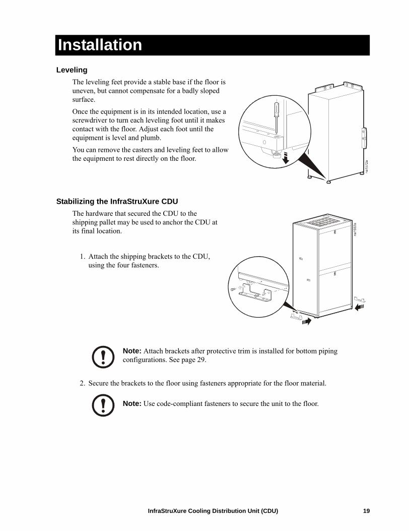
LevelingThe leveling feet provide a stable base if the floor is uneven, but cannot compensate for a badly sloped surface. Once the equipment is in its intended location, use a screwdriver to turn each leveling foot until it makes contact with the floor. Adjust each foot until the equipment is level and plumb.You can remove the casters and leveling feet to allow the equipment to rest directly on the floor.
Stabilizing the InfraStruXure CDUThe hardware that secured the CDU to the shipping pallet may be used to anchor the CDU at its final location.
1. Attach the shipping brackets to the CDU, using the four fasteners.
2. Secure the brackets to the floor using fasteners appropriate for the floor material.
Note: Attach brackets after protective trim is installed for bottom piping configurations. See page 29.
Note: Use code-compliant fasteners to secure the unit to the floor.
InfraStruXure Cooling Distribution Unit (CDU) 19

Removing the Panels
Front panel removal
.
Side panel removal1. Remove each of the four panel plugs.
20 InfraStruXure Cooling Distribution Unit (CDU)

Installation: Removing the Panels
2. Insert the T-30 end of the wrench into the recessed screw, then turn the wrench counter-clockwise one full turn. Do this for all four recessed screws.
3. Lift the side panel up, and then away from the unit.
InfraStruXure Cooling Distribution Unit (CDU) 21

Connections
Chilled water piping to the CDU
Pipe size. The chilled water supply and return connections on the CDU are 3-inch NPT isolation valves, and strainers with stainless steel, 20 mesh filters must be installed between the chiller and CDU. Connection to the CDU can be with hard or flexible piping.
Note: To minimize obstructions, install particulate strainers and filters on the supply line coming into the CDU. Locate strainers between the CDU and any other devices on the chilled water supply line.
Note: A redundant strainer in the bypass line is recommended for systems with possible debris or heavy particulates.
CDU
CDU
Bottom piping
Top piping
To Customer-Supplied
Chiller
To Customer-Supplied
Chiller
22 InfraStruXure Cooling Distribution Unit (CDU)

Installation: Connections
Brass NPT connections
The outer diameter of the union measures 4.75 in (121 mm) from flat surface to flat surface. Use a pipe wrench with a jaw size of at least 5 in (127 mm). The wrench should be at least 36 in (915 mm) long in order to apply enough force to achieve a proper seal.
Insulation. Insulate supply and return water lines to minimize condensation. Seal all seams. Properly installed insulation will prevent condensation.
Corrosion Hazard: Protection against galvanic corrosion is strongly recommended if using dissimilar metals.
Caution: Wrenches must be of adequate size in order to achieve a proper seal at the union connection.
Caution: Make sure wrenches are used only on the flat surfaces of the union.
Correct Incorrect
InfraStruXure Cooling Distribution Unit (CDU) 23

Installation: Connections
Distribution piping installation and connectionsThe preferred system to connect the CDU and InfraStruXure InRow RC units is PEX-AL-PEX piping and MultiPress fittings.
Using your pipe diagram as a reference, start by loosely hanging the longest set of supply and return pipes from their support braces.
Connecting the CDU1. Carefully remove the insulation covering the
valve handles and the tops of the valves. Set aside to be installed later.
Note: Do not combine other fittings or piping with the products supplied by APC.
See section four of the tool operation guide labeled “MultiPress Fittings Installation Instructions” for proper installation of the MultiPress Fittings and PEX-AL-PEX piping.
Note: It helps to mark each pipe as either “supply” or “return” before making the final connection. Use a marker pen to mark each pipe and piping header (for both supply and return) S1, S2 and R1, R2 etc.
24 InfraStruXure Cooling Distribution Unit (CDU)

Installation: Connections
2. Remove the couplings from the top of the valves. Remove and discard the stainless steel protective disk from under each valve coupling.
3. Apply liquid thread sealant to the threads of each fitting. Follow the sealant manufacturer’s instructions for cure time before proceeding.
4. Attach a valve coupling to each fitting (use the 7/8-inch hex key and an adjustable wrench for this procedure).
5. Route the pipes through the roof panel or floor pan to the designated supply and return valves.
6. Chamfer each pipe end, then insert the pipe into the fitting so that the pipe is visible in the indicator hole, and crimp.
7. Attach each pipe and fitting to the appropriate supply or return valve and secure the union nut hand tight plus an additional 1/4 turn.
Note: Make sure the inside of the pipe is clean of debris and plastic shavings after chamfering.
Indicator hole
InfraStruXure Cooling Distribution Unit (CDU) 25

Installation: Connections
Connecting the InRow RC1. Insert a fitting into each of the supply and return connection
pipes (hand tighten only).
2. Mark each pipe for cut length, and cut.
3. Remove both fittings, and apply liquid thread sealant to the threads of each fitting.
4. Re-insert the fittings into the inlet and return pipes, and tighten in place.
5. Chamfer each pipe, then insert the pipe into the fitting so that the pipe is visible in the indicator hole, and crimp.
Repeat steps for each InRowRC unit attached to the CDU.
Leak testWhen all pipe runs are completed, and before installing the insulation, perform a leak test on the system. Bring pressurized air or nitrogen into the equipment to reach the maximum working pressure. See table on page 38. Ensure there are no leaks before introducing water into the system
Caution: Do not overtighten the couplings that connect the pipe fittings. Doing so may deform the threads and create possible leaks.
Note: Make sure the inside of the pipe is clean of debris and plastic shavings after chamfering.
Cut length
Caution: Introduction of water to the system without prior testing for leaks could result in damage to other equipment in the vicinity.
26 InfraStruXure Cooling Distribution Unit (CDU)

Installation: Connections
Piping insulationUse only approved insulation. The closed cell insulation with sealing seams has an inner diameter of 1 3/8 in (34.9 mm), and is 1/2 in (12.7 mm) thick. All horizontal insulation sections must be installed with seams facing up. Each section of insulation must be glued to the adjacent section. Any insulation sections that must be fitted around piping support clamps (other than supplied clamps) must be glued together to prevent leaks.
1. Replace the insulation that was removed from the valves.
2. Insulate each run of piping.
Note: At each InRow RC, attach an identification label (1–12) to the insulation sleeve of the supply and return pipes that corresponds to the number at the valves on the CDU.
InfraStruXure Cooling Distribution Unit (CDU) 27

Installation: Connections
Pipe clampsPipe clamps are provided to properly secure the PEX-AL-PEX piping. Always refer to local and national codes for regional specifications on spacing and anchoring of the pipe clamps.
Condensate drain pipingThe CDU is equipped with a condensate pan located in the bottom of the unit. Any moisture will be collected here and directed to a drain port in the pan. A 6 in × 1/4 in (152 mm x 6 mm) (inner diameter) condensate drain tube is supplied for use with this unit. Connect this tubing and route it to an open drain.
Condensate drain to floor dimension. The distance of the drain from the floor about 13/16 in (20 mm x 6 mm) ± 1/4 in. This is a consideration when using a condensate pump with the CDU
See table Guidelines for Spacing Between Clamps on page 39.
For clamp installation, follow instructions in the InfraStruXure PEX-AL-PEX Piping Clamp Installation Sheet.
Note: Use code-compliant piping practices when installing the condensate drain line to an open drain.
Drain Tube
Condensate Pan
Dimensions are in inches (millimeters)
28 InfraStruXure Cooling Distribution Unit (CDU)

Protective Trim
Top piping configurationThe CDU is shipped with an unassembled protective trim assembly to shroud the pipe egress on the top of the unit. After the piping installation is complete, assemble the three pieces with the provided fasteners, and install the assembly to the top of the CDU.
Bottom piping configurationThe equipment may be shipped with unassembled protective trim for the bottom of the unit. This assembly conceals and protects the pipes between the bottom of the CDU and the floor. After the piping installation is complete, assemble and install the trim with the provided fasteners.
If the shipping brackets (page 19) will be used, they may now be attached to secure the CDU to the floor.
InfraStruXure Cooling Distribution Unit (CDU) 29
Commissioning
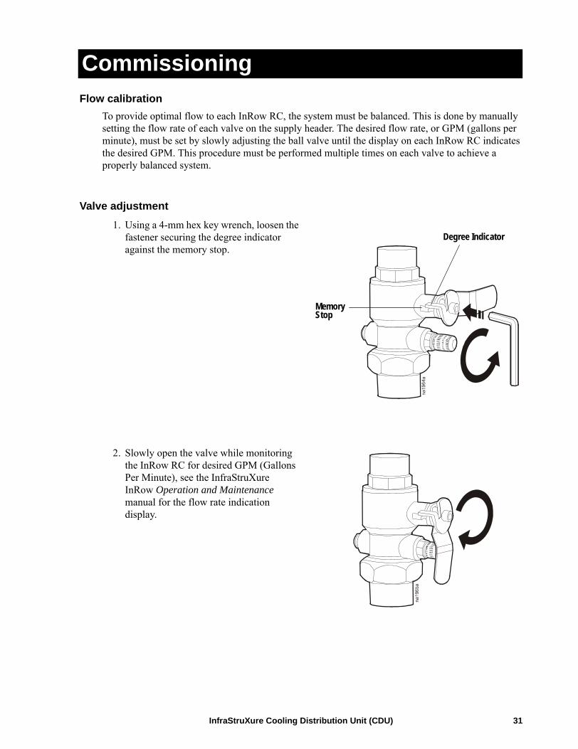
Flow calibrationTo provide optimal flow to each InRow RC, the system must be balanced. This is done by manually setting the flow rate of each valve on the supply header. The desired flow rate, or GPM (gallons per minute), must be set by slowly adjusting the ball valve until the display on each InRow RC indicates the desired GPM. This procedure must be performed multiple times on each valve to achieve a properly balanced system.
Valve adjustment1. Using a 4-mm hex key wrench, loosen the
fastener securing the degree indicator against the memory stop.
2. Slowly open the valve while monitoring the InRow RC for desired GPM (Gallons Per Minute), see the InfraStruXure InRow Operation and Maintenance manual for the flow rate indication display.
MemoryStop
Degree Indicator
InfraStruXure Cooling Distribution Unit (CDU) 31

Commissioning
3. Once the valve is opened to a point where the desired flow rate has been achieved on the InRow RC, hold the degree indicator against the memory stop and tighten the fastener.
Repeat step 3 for each valve in the system, and then again for each valve after all the valves have been adjusted. These steps must be performed multiple times on each valve to achieve a properly balanced system.
When calibration is complete, replace the insulating covers on the valve handles. Apply glue to seal them to the insulation surrounding the valve.
DegreeIndicator
MemoryStop
32 InfraStruXure Cooling Distribution Unit (CDU)

Checklists
Initial InspectionMechanical Inspection
of
Ensure that the:
Installation is complete according to this installation manual.
InfraStruXure CDU shows no signs of damage.
Available clearance around the unit is in accordance with ASHRAE, local, and national codes, as well as this installation manual.
The unit has been secured to the floor.
Ensure that the:
Condensate drain line is the size of the drain connection and is routed properly.
Mechanical connections are tight.
Isolation valves are installed on the supply and return lines.
Strainers have been installed in the supply line to the unit.
A by-pass line with strainer and isolation valves has been installed in the supply line to the unit.
Piping is insulated.
Piping does not have any leaks.
External chilled water isolation valves are open.
Air is bled from the system. If air remains in the system, bleed it out now.
Supply water temperature is within specifications.
Water flow balance between each CRAC and the CDU is correct.
Caution: Failure to properly install piping may result in improper InfraStruXure CDU operation.
InfraStruXure Cooling Distribution Unit (CDU) 33

Final Inspection\
Ensure that the:
Interior and exterior of the unit are clean and free from debris.
Panels are locked and keys are secure.
Packaging materials are disposed of properly.
The start-up form is filled in and sent to APC.
34 InfraStruXure Cooling Distribution Unit (CDU)

Warranty
Warranty StatementThe limited warranty provided by American Power Conversion Corporation (“APC”) in this Statement of Limited Factory Warranty applies only to Products you purchase for your commercial or industrial use in the ordinary course of your business.
LIMITED FACTORY WARRANTY
APC product coveredInfraStruXure Cooling Distribution Unit (CDU)
Terms of warrantyAPC warrants that the Product shall be free from defects in materials and workmanship for a period of one (1) year from the date of start-up when APC authorized service personnel performed the start-up of the Product, or a maximum of 18 months from the date of Product shipment from APC, when APC authorized service personnel have not performed the start-up of the Product (“Warranty Period”). In the event that the Product fails to meet the foregoing warranty, APC shall repair or replace any defective parts, such repair or replacement to be without charge for on-site labor and travel if APC authorized personnel have conducted start-up of the Product. An APC Start-Up Service must be performed/completed by APC authorized service personnel or replacement of defective parts only will be covered. APC shall have no liability and no obligation to repair the installed Product if non-authorized personnel performed the start-up and such start-up caused the Product to be defective. Any parts furnished under this warranty may be new or factory-remanufactured. This warranty does not cover circuit breaker resetting, loss of refrigerant, consumables, or preventative maintenance items. Repair or replacement of a defective product or part thereof does not extend the original warranty period.
Non-transferable Warranty extends to first purchaser for useThis Warranty is extended to the first person, firm, association or corporation (herein referred to by “You” or “Your”) for whom the APC Product specified herein has been purchased. This Warranty is not transferable or assignable without the prior written permission of APC.
Assignment of warrantiesAPC will assign to you any warranties which are made by manufacturers and suppliers of components of the APC Product and which are assignable. Any such warranties are assigned “AS IS” and APC makes no representations as to the effectiveness or extent of such warranties, assumes NO RESPONSIBILITY for any matters which may be warranted by such manufacturers or suppliers and extends no coverage under this Warranty to such components.
InfraStruXure Cooling Distribution Unit (CDU) 35
Warranty: Warranty Statement
Drawings, descriptionsAPC warrants for the Warranty Period and on the terms of the Warranty set forth herein that the APC Product will substantially conform to the descriptions contained in the APC Official Published Specifications or any of the drawings certified and agreed to by an authorized APC representative, if applicable thereto (“Specifications”). It is understood that the Specifications are not warranties of performance and not warranties of fitness for a particular purpose.
Warranty claims procedureTo obtain service under Warranty, contact APC Customer Support at the number on the back cover of this manual. You will need the model number of the Product, the serial number, and the date purchased. A technician will ask you to describe the problem. If it is determined that the Product will need to be returned to APC you must obtain a returned material authorization (RMA) number from APC Customer Support. Products that must be returned must have the RMA number marked on the outside of the package, and be returned with transportation charges prepaid. If it is determined by APC Customer Support that on-site repair of the Product is allowed, APC will arrange to have APC authorized service personnel dispatched to the Product location to repair or replace the Product at the discretion of APC.
ExclusionsAPC shall not be liable under the Warranty if its testing and examination discloses that the alleged defect in the product does not exist or was caused by your or any third person’s misuse, negligence, improper installation or testing, unauthorized attempts to repair or modify, or any other cause beyond the range of the intended use, or by accident, fire, lightning or other hazard.
THERE ARE NO WARRANTIES, EXPRESSED OR IMPLIED, BY OPERATION OF LAW OR OTHERWISE, OF PRODUCTS SOLD, SERVICED OR FURNISHED UNDER THIS AGREEMENT OR IN CONNECTION HEREWITH. APC DISCLAIMS ALL IMPLIED WARRANTIES OF MERCHANTABILITY, SATISFACTION AND FITNESS FOR A PARTICULAR PURPOSE. THE APC EXPRESS WARRANTIES WILL NOT BE ENLARGED, DIMINISHED, OR AFFECTED BY AND NO OBLIGATION OR LIABILITY WILL ARISE OUT OF APC RENDERING TECHNICAL OR OTHER ADVICE OR SERVICE IN CONNECTION WITH THE PRODUCTS. THE FOREGOING WARRANTIES AND REMEDIES ARE EXCLUSIVE AND IN LIEU OF ALL OTHER WARRANTIES AND REMEDIES. THE WARRANTIES SET FORTH ABOVE, CONSTITUTE SOLE LIABILITY OF APC AND YOUR EXCLUSIVE REMEDY FOR ANY BREACH OF SUCH WARRANTIES. THE WARRANTIES EXTEND ONLY TO YOU AND ARE NOT EXTENDED TO ANY THIRD PARTIES.IN NO EVENT SHALL APC, ITS OFFICERS, DIRECTORS, AFFILIATES OR EMPLOYEES BE LIABLE FOR ANY FORM OF INDIRECT, SPECIAL, CONSEQUENTIAL OR PUNITIVE DAMAGES ARISING OUT OF THE USE, SERVICE OR INSTALLATION OF THE PRODUCTS, WHETHER SUCH DAMAGES ARISE IN CONTRACT OR TORT, IRRESPECTIVE OF FAULT, NEGLIGENCE OR STRICT LIABILITY OR WHETHER APC HAS BEEN ADVISED IN ADVANCE OF THE POSSIBILITY OF SUCH DAMAGE.
36 InfraStruXure Cooling Distribution Unit (CDU)

Specifications
Weight lbs (kgs)
Net weight 500 (227.27)
Operating weight 530 (240.91)
Shipping weight 587 (266.82)
Nominal Dimensions in (mm)
Net height (not including pipe shroud) 78.5 (1993)
Shipping height 85 (2159)
Net width 42 (1067)
Shipping width 48 (1219)
Net depth 30 (762)
Shipping depth 36 (914)
Connection Sizes in (mm) - Nominal
Supply to InRow RC 1 (25.4)
Return from InRow RC 1 (25.4)
Main supply from chiller 3 (76.2)
Main return from chiller 3 (76.2)
Control Valves in (mm) - Nominal
Isolation ball valve 1 (25.4)
Balancing ball valve 1 (25.4)
Flow Rate GPM (l/s)
Flow rate 144 (9.08)
Maximum flow rate of CDU 175 (11.4)
Maximum circuit flow rate 20.2 (1.27)
InfraStruXure Cooling Distribution Unit (CDU) 37

Specifications
Working Pressure psi (kPa)
Maximum working pressure of CDU 150 (1035)
Recommended Coolant Requirements °F (°C)
Entering water temperature 45–55 (7.2–12.8)
Relative Humidity
Chilled Water/Glycol 45 °F (7.2°C)
Maximum Dry Bulb Temperature 90 °F (32.2°C)
Percent Relative Humidity 40%
Note: Properly installed insulation will prevent condensation at this condition. Additional insulation may be required for higher dew points or lower water/glycol temperatures.
Scalability
Maximum # of InRow RC units supported 12
Minimum # on InRow RC units supported 1
Maximum length of PEX-AL-PEX pipe between the CDU and InRow RC
150 ft (45.72 m)
CDU Pressure DropNumber of InRow RC units supported
Flow rate through PEX-AL-PEX pipe
Total pressure drop
Quantity GPM (l/s) Feet of Water (kPa)
1–12 2 (0.13) 0.2 (0.6)
1–12 4 (0.25) 0.9 (2.7)
1–12 6 (0.38) 2 (6.0)
1–12 8 (0.50) 3.4 (10.2)
1–12 10 (0.63) 5.3 (15.9)
1–12 12 (0.76) 7.6 (22.7)
1–10 16 (1.00) 10.2 (30.5)
1–9 18 (1.14) 16.7 (49.9)
1–9 18.5 (1.17) 17.6 (52.6)
38 InfraStruXure Cooling Distribution Unit (CDU)

Specifications
Guidelines for Spacing Between Clamps
PEX-AL-PEX – 1 in (25 mm) Inner Diameter
Minimum support distance horizontal – in (mm)
Minimum support distance vertical – in (mm)
International Plumbing Code - Section 308 Piping Support, Table 308.5 Hanger Spacing
32 (813) 42 (1219)
Uponor Multi-layer Composite Piping Systems Installation Guide Installation Manual
63 (1600) 63 (1600)
IAPMO/ANSI UPC 1-2003 - Uniform Plumbing Code Table 3-2 Hangers and Supports
98 (2489) Base and each floor.Provide mid-story.
PEX-AL-PEX Weight With and Without Fluid1 in (25 mm) Inner Diameter
Weight PEX-AL-PEX per unit length 0.218 lbs/ft (0.324 kg/m)
Volume of H2O per unit length 4.28 gal/ft (53.2 l/m)
Weigh oft H2O per unit length 0.357 lbs/ft (0.53 kg/m)
Weight of 40% propylene glycol solution by mass per unit length 0.371 lbs/ft (0.552 kg/m)
Weight of 150 ft (45.7 m) span of PEX-AL-PEX with 40% propylene glycol solution by mass
88.4 lbs (40.0 kg)
PEX-AL-PEX Pressure Drop - 1 in (25 mm) Inner Diameter
Flow Rate through PipeGPM (l/m)
Pressure Drop through pipeFeet of water/Feet of pipe (kPa/m)
2 (0.13) 0.004 (0.04)
4 (0.25) 0.01 (0.1)
6 (0.38) 0.03 (0.29)
8 (0.50) 0.05 (0.49)
10 (0.63) 0.07 (0.69)
12 (0.76) 0.1 (0.98)
14 (0.88) 0.13 (1.28)
16 (1.00) 0.17 (1.67)
18 (1.14) 0.21 (2.06)
18.5 (1.17) 0.21 (2.06)
InfraStruXure Cooling Distribution Unit (CDU) 39

Specifications
PEX-AL-PEX Pipe Bend Length for Pressure Drop*1 in (25 mm) Inner Diameter
Estimated number of bends in pipe Equivalent pipe length, ft (m)
1 1 (.31)
2 2 (.61)
3 3 (.92)
4 4 (1.22)
5 5 (1.53)
6 6 (1.83)
7 7 (2.14)
8 8 (2.44)
9 9 (2.75)
10 10 (3.05)
* For Pressure Drop Calculation only. Do not include equivalent pipe length in total PEX-AL-PEX length for installation.
Note: Pressure drop of the system should be based on the highest individual circuit, which is dependent on line length and flow rate.
40 InfraStruXure Cooling Distribution Unit (CDU)


06/2006990-2823A-001*990-2823A-001*
Customer support for this or any other APC product is available at no charge in any of the following ways:• Visit the APC Web site to access documents in the APC Knowledge Base and to submit customer
support requests.– www.apc.com (Corporate Headquarters)
Connect to localized APC Web sites for specific countries, each of which provides customer support information.
– www.apc.com/support/Global support searching APC Knowledge Base and using e-support.
• Contact an APC Customer Support center by telephone or e-mail.– Regional centers:
– Local, country-specific centers: go to www.apc.com/support/contact for contact information.
Contact the APC representative or other distributor from whom you purchased your APC product for information on how to obtain local customer support.
Direct InfraStruXure Customer Support Line
(1)(877)537-0607 (toll free)
APC headquarters U.S., Canada
(1)(800)800-4272 (toll free)
Latin America (1)(401)789-5735 (USA)
Europe, Middle East, Africa
(353)(91)702000 (Ireland)
Japan (0) 35434-2021
Australia, New Zealand, South Pacific area
(61) (2) 9955 9366 (Australia)
Entire contents copyright 2006 American Power Conversion Corporation. All rights reserved. Reproduction in whole or in part without permission is prohibited. APC, the APC logo, and InfraStruXure
are trademarks of American Power Conversion Corporation. All other trademarks, product names, and corporate names are the property of their respective owners and are used for informational purposes only.
APC Worldwide Customer Support