
Infrastructure Standards and Specifications
157
Infrastructure Standards and Specifications These specifications and drawings will be revised from time to time as considered necessary by the City. It is the responsibility of the owner and the professional engineer in charge of the work to verify that it has been done in accordance with the latest revision of these Specifications.
Transcript of Infrastructure Standards and Specifications

Infrastructure Standards and Specifications These specifications and drawings will be revised from time to time as considered necessary by the City. It is the responsibility of the owner and the professional engineer in charge of the work to verify that it has been done in accordance with the latest revision of these Specifications.

Revision Date March 2020
2
Section 1 – General ......................................................................................... 11
1.1 Definitions ...................................................................................................................... 11
1.2 Acronyms ........................................................................................................................ 12
1.3 Geotechnical Report ................................................................................................... 12
1.4 Familiarization .............................................................................................................. 12
1.5 AODA ................................................................................................................................ 12
Section 2 – Engineering Requirements for Subdivisions .................. 13
2.1 Engineering Requirements for Draft Plan Approval ....................................... 13
2.2 Submissions for Subdivision Development ........................................................ 14
2.2.1 Preliminary Drawings .............................................................................................. 14 2.2.2 First Submission ....................................................................................................... 15 2.2.3 Municipal Roadway Structure Submission ........................................................... 15 2.2.4 Landscaping Submission (if required) .................................................................. 16 2.2.5 Subsequent Submissions ........................................................................................ 16 2.2.6 Final Submission ...................................................................................................... 16 2.2.7 Other .......................................................................................................................... 17 2.2.8 Preparation of the Subdivision Agreement .......................................................... 18 2.2.9 Requirements Prior to Commencement of Construction ................................... 18
2.3 Engineering Drawing Requirements .................................................................... 19
2.3.1 General Requirements ............................................................................................ 19 2.3.2 General Plans............................................................................................................ 19 2.3.3 Storm Drainage Plans ............................................................................................. 20 2.3.4 Sanitary Drainage Plans .......................................................................................... 20 2.3.5 Grading Plans ........................................................................................................... 21 2.3.6 Plan and Profile Drawings ...................................................................................... 21 2.3.7 Erosion and Sediment Control Plans ..................................................................... 22 2.3.8 Landscaping Plans ................................................................................................... 22 2.3.9 Detail Drawings ........................................................................................................ 23
2.4 Inspection and Testing .............................................................................................. 23
2.4.1 Inspection ................................................................................................................. 23 2.4.2 Testing ....................................................................................................................... 24
2.5 Construction .................................................................................................................. 25
2.5.1 Backfill Material ........................................................................................................ 25
2.6 Acceptance of Works .................................................................................................. 26
2.6.1 Servicing (Excluding Stormwater Management Facilities) ................................. 26 2.6.2 Stormwater Management Facilities ....................................................................... 28 2.6.3 Assumption ............................................................................................................... 30

Revision Date March 2020
3
2.7 Record Drawings .......................................................................................................... 30
2.7.1 General ...................................................................................................................... 30 2.7.2 “As-constructed” Field Survey ................................................................................ 31 2.7.3 Drawing Revisions .................................................................................................... 31
Section 3 – Engineering Requirements for Site Plan Control ..........34 3.1 General ........................................................................................................................... 34 3.2 Submission Review....................................................................................................... 34 3.3 Grading / Servicing Plans ............................................................................................ 34 3.4 Stormwater Management Requirements .................................................................. 35 3.5 Landscaping Plans ........................................................................................................ 35 3.6 Work Proposed on City Roadways ............................................................................. 35 3.7 Connection to City Sanitary Sewer System .............................................................. 35 3.8 Inspection and Certification of Works ....................................................................... 36 3.9 As-Constructed Plans ................................................................................................... 36
Section 4 – Roadways .....................................................................................37
4.1 General ............................................................................................................................. 37
4.2 Geometric Design Elements ..................................................................................... 37
4.2.1 Vertical Curves .......................................................................................................... 38 4.2.2 Backfall at Intersecting Streets .............................................................................. 38 4.2.3 Centreline Radii ........................................................................................................ 38 4.2.4 Radii for Curb & Gutter ........................................................................................... 38 4.2.5 Daylighting Requirements at Intersections .......................................................... 39 4.2.6 Cul-de-Sac and Bulbs............................................................................................... 39 4.2.7 Temporary Turning Circles ..................................................................................... 39 4.2.8 Roundabouts ............................................................................................................. 39 4.2.9 Turning Lanes ........................................................................................................... 39 4.2.10 Utilities ....................................................................................................................... 40
4.3 Special Road Designs .................................................................................................. 40
4.4 Pavement Design ......................................................................................................... 40
4.5 Construction Requirements ..................................................................................... 42
4.5.1 Clearing, Grubbing, and Area Rough Grading ..................................................... 42 4.5.2 Road Construction .................................................................................................... 42 4.5.3 Road Subdrains ........................................................................................................ 42 4.5.4 Requirements Prior to Surface Course Asphalt ................................................... 43 4.5.5 Tack Coat .................................................................................................................. 43 4.5.6 Asphalt Paving Operations ...................................................................................... 43 4.5.7 Other Requirements ................................................................................................ 44 4.5.8 Road Occupancy Permits – Scheduled for 2021 ................................................. 44

Revision Date March 2020
4
4.6 Curbs and Gutters........................................................................................................ 45
4.7 Sidewalks and Walkways ......................................................................................... 45
4.7.1 Rest Areas ................................................................................................................. 46
4.8 Bicycle Lanes and Multi-Use Trails ........................................................................ 46
4.9 Bus Bays .......................................................................................................................... 46
4.10 Driveway Entrances ................................................................................................ 46
4.10.1 Minimum Driveway Design ..................................................................................... 47 4.10.2 Driveway Grades ...................................................................................................... 47 4.10.3 Driveway Depressions ............................................................................................. 47
4.11 Boulevards ................................................................................................................. 47
4.11.1 Open Ditches ............................................................................................................ 48
4.12 Hydro Servicing ........................................................................................................ 48
4.13 Subdivision Street Lighting ................................................................................. 48
4.13.1 General ...................................................................................................................... 48 4.13.2 Lighting Levels ......................................................................................................... 49 4.13.3 Photometrics ............................................................................................................. 50 4.13.4 Drawings ................................................................................................................... 50 4.13.5 Assumption of the Subdivision............................................................................... 50 4.13.6 Installation ................................................................................................................ 50 4.13.7 Material Specifications ............................................................................................ 51
4.14 Fencing ........................................................................................................................ 51
4.15 Easement Requirements ....................................................................................... 52
4.15.1 General ...................................................................................................................... 52 4.15.2 Storm Sewer, Sanitary Sewer, and Watermain Easements .............................. 52 4.15.3 Open Channels ......................................................................................................... 52 4.15.4 Overland Surface Flow ............................................................................................ 52
4.16 Materials ..................................................................................................................... 52
4.16.1 Concrete Mix for Sidewalk and Curb and Gutter ................................................ 52 4.16.2 Superpave and Mix Design ..................................................................................... 53 4.16.3 Granular ‘B’ ............................................................................................................... 53
Section 5 – Sanitary Sewers ........................................................................ 54
5.1 Sanitary Sewer System ............................................................................................. 54
5.1.1 General ...................................................................................................................... 54 5.1.2 Non Permitted Flows ............................................................................................... 54 5.1.3 Abandonment of Existing Sewers .......................................................................... 54

Revision Date March 2020
5
5.2 Hydraulic Design .......................................................................................................... 54
5.2.1 Confirmation of Capacity ......................................................................................... 54 5.2.2 Sanitary Drainage Plan ............................................................................................ 55 5.2.3 Flow Calculations ...................................................................................................... 55
5.3 Sanitary Sewer Design ............................................................................................... 56
5.3.1 Location ..................................................................................................................... 56 5.3.2 Pipe Capacity ............................................................................................................ 56 5.3.3 Flow Velocity ............................................................................................................. 56 5.3.4 Minimum Size ............................................................................................................ 57 5.3.5 Minimum Grade ........................................................................................................ 57 5.3.6 Depth ......................................................................................................................... 57 5.3.7 Curved Sewers .......................................................................................................... 57 5.3.8 Limits .......................................................................................................................... 57 5.3.9 Pipe Crossings ........................................................................................................... 57 5.3.10 Changes in Pipe Size ................................................................................................ 57 5.3.11 Pipe Bedding ............................................................................................................. 58
5.4 Maintenance Holes ...................................................................................................... 58
5.4.1 Location ..................................................................................................................... 58 5.4.2 Maximum Spacing .................................................................................................... 58 5.4.3 Maintenance Hole Types ......................................................................................... 58 5.4.4 Maintenance Hole Design ....................................................................................... 59 5.4.5 Minimum Invert Drop .............................................................................................. 59 5.4.6 Maintenance Hole Lids/Covers ............................................................................... 60 5.4.7 Grades for Maintenance Hole Frame and Covers ................................................ 60
5.5 Sanitary Service Connections .................................................................................. 60
5.5.1 Location ..................................................................................................................... 61 5.5.2 Connection to the Main ........................................................................................... 61 5.5.3 Connections to Maintenance Holes ....................................................................... 61 5.5.4 Minimum Size and Grade ........................................................................................ 61 5.5.5 Depth ......................................................................................................................... 61 5.5.6 Connection to Commercial / Industrial / Institutional and other Blocks.......... 62
5.6 Pipe Materials ................................................................................................................ 62
5.7 Testing ............................................................................................................................. 63
5.7.1 General ...................................................................................................................... 63 5.7.2 Infiltration Test ......................................................................................................... 63 5.7.3 Exfiltration Test ........................................................................................................ 63 5.7.4 Deflection Test .......................................................................................................... 64 5.7.5 Video Record ............................................................................................................. 65

Revision Date March 2020
6
Section 6 – Storm Drainage and Stormwater Management ............ 66
6.1 Erosion and Sediment Control ................................................................................ 66
6.1.1 Topsoil Stockpiles .................................................................................................... 66 6.1.2 Silt Fence ................................................................................................................... 66 6.1.3 Temporary Drainage Swales .................................................................................. 67 6.1.4 Straw Bale Filters ..................................................................................................... 67 6.1.5 Rock Check Dams .................................................................................................... 67 6.1.6 Rip Rap ...................................................................................................................... 67 6.1.7 Catchbasin Sediment Control ................................................................................. 67 6.1.8 Stone Pad Construction Entrance – Construction Access .................................. 67 6.1.9 Temporary Connections to Storm Sewer ............................................................. 68 6.1.10 Construction Dewatering ........................................................................................ 68 6.1.11 ESC Phasing .............................................................................................................. 68
6.2 Storm Sewer System .................................................................................................. 70
6.2.1 General ...................................................................................................................... 70 6.2.2 Abandonment of Existing Sewers .......................................................................... 70
6.3 Hydraulic Design .......................................................................................................... 71
6.3.1 Storm Drainage Plans ............................................................................................. 71 6.3.2 Rational Method ....................................................................................................... 71 6.3.3 Design Storms .......................................................................................................... 72 6.3.4 Rainfall Intensity ...................................................................................................... 72 6.3.5 Time of Concentration ............................................................................................ 73 6.3.6 Runoff Coefficient .................................................................................................... 73
6.4 Storm Sewer Design ................................................................................................... 74
6.4.1 Location ..................................................................................................................... 74 6.4.2 Pipe Capacity ............................................................................................................ 74 6.4.3 Flow Velocities .......................................................................................................... 74 6.4.4 Minimum Sizes .............................................................................................................. 75 6.4.5 Minimum Grades ...................................................................................................... 75 6.4.6 Depth ......................................................................................................................... 75 6.4.7 Curvilinear Sewers ................................................................................................... 75 6.4.8 Elliptical Sewers ....................................................................................................... 75 6.4.9 Limits ......................................................................................................................... 75 6.4.10 Pipe Crossings .......................................................................................................... 75 6.4.11 Blind Connections .................................................................................................... 76 6.4.12 Changes in Pipe Size ............................................................................................... 76 6.4.13 Safety / Rodent Grates ........................................................................................... 76 6.4.14 Pipe Bedding ............................................................................................................. 76
6.5 Maintenance Holes ...................................................................................................... 76
6.5.1 Location ..................................................................................................................... 76 6.5.2 Maximum Spacing .................................................................................................... 76 6.5.3 Maintenance Hole Types ........................................................................................ 77 6.5.4 Tee Maintenance Holes ........................................................................................... 77

Revision Date March 2020
7
6.5.5 Maintenance Hole Design ....................................................................................... 77 6.5.6 Minimum Invert Drop .............................................................................................. 78 6.5.7 Frame and Cover ...................................................................................................... 78 6.5.8 Grades for Maintenance Hole Frames and Covers .............................................. 78
6.6 Catchbasins .................................................................................................................... 78
6.6.1 Location and Spacing .............................................................................................. 78 6.6.2 Catchbasin Types ..................................................................................................... 79 6.6.3 Catchbasin Connections .......................................................................................... 79 6.6.4 Frame and Grate ...................................................................................................... 79 6.6.5 Sumps ........................................................................................................................ 80 6.6.6 Rear Yard Drainage ................................................................................................. 80
6.7 Storm Service Connections ...................................................................................... 80
6.7.1 New Development .................................................................................................... 80 6.7.2 Infill or Redevelopment ........................................................................................... 80 6.7.3 Location ..................................................................................................................... 80 6.7.4 Minimum Slope and Diameter ................................................................................ 81 6.7.5 Depth ......................................................................................................................... 81 6.7.6 Flow Direction Changes ........................................................................................... 81 6.7.7 Rainwater Leaders ................................................................................................... 81
6.8 Channels and Culverts ................................................................................................ 81
6.8.1 Culverts and Bridges ................................................................................................ 81 6.8.2 Open Channels ......................................................................................................... 82 6.8.3 Watercourse Erosion and Bank Stability ............................................................... 82
6.9 Inlets and Outlets ........................................................................................................ 82
6.9.1 General ...................................................................................................................... 82 6.9.2 Inlets .......................................................................................................................... 82 6.9.3 Outlets ....................................................................................................................... 83
6.10 Materials ...................................................................................................................... 84
6.10.1 Pipe Materials............................................................................................................ 84 6.10.2 Maintenance Hole and Catchbasin Adjustment Units ......................................... 85
6.11 Testing ......................................................................................................................... 85
6.11.1 Deflection Test .......................................................................................................... 85 6.11.2 Video Record ............................................................................................................. 85
6.12 Stormwater Management ..................................................................................... 86
6.12.1 General Requirements ............................................................................................. 86 6.12.2 Stormwater Management Report .......................................................................... 87 6.12.3 Software .................................................................................................................... 88 6.12.4 Stormwater Management Plan ............................................................................... 88 6.12.5 Facility Monitoring, Maintenance and Operation ................................................. 89 6.12.6 Stormwater Management Components ................................................................ 89
Revision Date March 2020
8
Section 7 – Watermain ................................................................................... 93
7.1 General ............................................................................................................................ 93
7.2 Location and Design ................................................................................................... 93
7.2.1 Mains ......................................................................................................................... 93 7.2.2 Valves ........................................................................................................................ 95 7.2.3 Blow-offs ................................................................................................................... 96 7.2.4 Water Service ........................................................................................................... 96 7.2.5 Backflow Prevention ................................................................................................ 97 7.2.6 Service Valves .......................................................................................................... 97 7.2.7 Meters ........................................................................................................................ 98 7.2.8 Hydrants .................................................................................................................... 98 7.2.9 Chlorine Residual Maintenance .............................................................................. 99
7.3 Installation of Watermains ...................................................................................... 99
7.3.1 Ductile Iron ............................................................................................................... 99 7.3.2 Polyvinyl Chloride (PVC) ......................................................................................... 99 7.3.3 Line and Grade ......................................................................................................... 99 7.3.4 Frozen Ground ........................................................................................................ 100 7.3.5 Preparation of Trench ........................................................................................... 100 7.3.6 Dewatering ............................................................................................................. 100 7.3.7 Backfilling ................................................................................................................ 101 7.3.8 Compaction ............................................................................................................. 102 7.3.9 Lowering & Laying ................................................................................................. 102 7.3.10 Tracer Wire for Non Metallic Watermain ............................................................ 103 7.3.11 Bedding ................................................................................................................... 104 7.3.12 Connections to Ex. Mains, Jointing Watermains and Fittings ......................... 104 7.3.13 Jointing of Push on Joint Pipes ............................................................................ 105 7.3.14 Valves, Hydrants and Fittings .............................................................................. 105
7.4 Service Installation ................................................................................................... 106
7.4.1 Connecting Services to Mains .............................................................................. 106 7.4.2 PEXa/PE-RT Service Pipe ...................................................................................... 107 7.4.3 Copper Service Pipe .............................................................................................. 107 7.4.4 Tracer Wire ............................................................................................................. 107 7.4.5 Alignment & Grade ................................................................................................ 107 7.4.6 Restraints ................................................................................................................ 107 7.4.7 Electrical Grounding .............................................................................................. 108
7.5 Material ......................................................................................................................... 108
7.5.1 Watermain Pipe and Fittings ................................................................................ 108 7.5.2 Valves, Chambers and Rods ................................................................................. 110 7.5.3 Copper Pipe ............................................................................................................ 110 7.5.4 PEXa pipe ................................................................................................................ 110 7.5.5 PE-RT pipe .............................................................................................................. 110 7.5.6 Main Stops .............................................................................................................. 111 7.5.7 Curb Stops .............................................................................................................. 111

Revision Date March 2020
9
7.5.8 Curb Boxes .............................................................................................................. 111 7.5.9 Fittings ..................................................................................................................... 112 7.5.10 Meters ...................................................................................................................... 112 7.5.11 Hydrants .................................................................................................................. 112 7.5.12 Testing ..................................................................................................................... 112 7.5.13 Delivery .................................................................................................................... 112 7.5.14 Handling .................................................................................................................. 112 7.5.15 Storage .................................................................................................................... 113 7.5.16 Temporary Watermains ......................................................................................... 113 7.5.17 Anodes ..................................................................................................................... 114 7.5.18 Tracer Wire ............................................................................................................. 114 7.5.19 Insulated Watermain and Service pipe ............................................................... 114
7.6 Corrosion Protection ................................................................................................. 114
7.6.1 Non-Metallic Watermain ........................................................................................ 114 7.6.2 Metallic Watermain ................................................................................................ 114
7.7 Commissioning ............................................................................................................ 115
7.7.1 General .................................................................................................................... 115 7.7.2 Backflow .................................................................................................................. 115 7.7.3 Filling Pipe ............................................................................................................... 116 7.7.4 Swabbing ................................................................................................................. 116 7.7.5 Hydrostatic Pressure Test ..................................................................................... 116 7.7.6 Blocking and Blanking ........................................................................................... 117 7.7.7 Air Release Taps ..................................................................................................... 117 7.7.8 Disinfection .............................................................................................................. 117 7.7.9 Declorinating ........................................................................................................... 118 7.7.10 Chlorine Residual & Bacteriological Sampling .................................................... 119 7.7.11 Final Connection to Existing Water Distribution System .................................. 121 7.7.12 Valve Positioning .................................................................................................... 123
Section 8 – Site Grading .............................................................................. 124
8.1 Grading Requirements for Various Situations................................................. 124
8.1.1 Subdivisions ............................................................................................................ 124 8.1.2 Site Plans ................................................................................................................. 124 8.1.3 Severances, Lifting of Part Lot Control, Infill Lots ............................................ 124 8.1.4 Blocks ....................................................................................................................... 124 8.1.5 Capital Projects ....................................................................................................... 125 8.1.6 Variations / Modifications ...................................................................................... 125
8.2 Overland Flow Routes .............................................................................................. 125
8.3 Grading Design Standards ...................................................................................... 126
8.3.1 Drainage .................................................................................................................. 126 8.3.2 Slopes ....................................................................................................................... 127 8.3.3 Swales ...................................................................................................................... 127 8.3.4 Catchbasins ............................................................................................................. 127

Revision Date March 2020
10
8.3.5 Retaining Walls ...................................................................................................... 128
8.4 Subdivision Lot Grading Plans .............................................................................. 128
Section 9 – City of Stratford Std. Dwg.s ................................................ 129 Appendix A – City of Stratford Water Service Regulations Appendix B – Commissioning Plan Template Appendix C – Sewage Works Under the Transfer of Review Program Note: This updated document contains significant revisions to many items. It is the responsibility of each user to familiarize themselves with the current standards. In particular, the following updates have been completed (not a complete list):
Update to procedures and specifications for engineering design drawing submissions Update to asphalt standards, specifications and construction methods Clarification of Stormwater management facilities, maintenance and acceptance Clarification of minimum acceptable sanitary sewer flow velocities Update to maximum manhole spacings Water service material updates Update to hydrant and curb stop specifications

Revision Date March 2020
11
Section 1 – General The purpose of this document is to outline the minimum design requirements for the construction of works within the City of Stratford on existing and future municipally owned road allowances and other property, and for existing and future municipally owned infrastructure on easements. Engineering requirements for private developments carried out under the conditions of Site Plan Control will also be outlined. These requirements are general in nature and do not relieve the Designer or Developer of their responsibility to submit a complete product that demonstrates competent engineering design in full compliance with all applicable legislation. The specifications outlined in this document must be applied to all design applications. It is recognized that in some instances, unique circumstances may arise where some requirements cannot be accommodated. In these cases, the onus is on the proponent to demonstrate how the proposed design deviates from the requirements. Any deviation from the minimum City standards shall be specifically referred to by the applicant and/or their agent with a copy of written approval from the City attached to the design submission. These specifications and drawings will be revised from time to time as considered necessary by the City. It is the responsibility of the owner and their representative professional engineer in charge of the work to verify that it has been done in accordance with the latest revision of these Specifications. Where any portion of work is not covered by the City standards, the appropriate Ontario Provincial Standard Specification shall apply.
1.1 Definitions City shall mean the Corporation of the City of Stratford. City Engineer shall mean the Director of Infrastructure and Development Services, their appointee or agents. Consultant shall mean the firm of Consulting Engineers who have been retained by the City or Developer to act as their agent for the design of City owned infrastructure or the Development of lands and installation of the services herein. Developer/Owner shall mean the owner, its heirs, executors, administrators, successors and assigns and agents thereof or contractor or subcontractor carrying out the Works for or on behalf of the Owner or Owners. Engineering Division shall mean the Department of Infrastructure and Development Services. Inspector shall mean an inspector for the City Engineer. Professional Engineer shall only mean those individuals who have demonstrated that they possess the necessary qualifications and have been licensed by Professional Engineers of Ontario.

Revision Date March 2020
12
1.2 Acronyms AODA – Accessibility for Ontarians with Disabilities Act AWWA – American Water Works Association DFO – Department of Fisheries and Oceans Canada EC – Environment Canada ED – Engineering Division within the Infrastructure and Development Services Department IDS – Infrastructure and Development Services Department at the City of Stratford MAH – Ministry of Municipal Affairs and Housing MECP – Ministry of the Environment, Conservation and Parks MNR – Ministry of Natural Resources and Forestry MTO – Ministry of Transportation OBC – Ontario Building Code OMAFRA – Ministry of Agriculture, Food, and Rural Affairs TAC – Transportation Association of Canada UTRCA – Upper Thames River Conservation Authority
1.3 Geotechnical Report A geotechnical report must be submitted to the City Engineer as part of the design of municipal roads, watermain, sanitary sewer and storm sewer systems unless otherwise waived by the City Engineer. As a minimum, recommendations must be made regarding the pavement structure, watermain and sewer bedding, trench backfill, thrust restraints, corrosion protection, trench slopes and trench dewatering and pipe selection. The resistivity of the soil must also be provided. In addition, recommendations must be made pertaining to building construction including for building footings, foundations, bearing capacities, foundation drainage, water table elevations and any perched water.
1.4 Familiarization Prior to the commencement of the Engineering Design, the Consultant shall obtain copies of the City’s “Infrastructure Standards and Specifications” and “Standard Detailed Drawings” to familiarize themselves with the requirements of infrastructure, subdivision, and/or site plan design in the City. The onus will be on the Consultant and Owner to arrange meetings with the City’s Engineering and Planning Departments to discuss areas of preliminary concern and other data prior to commencement of the engineering design.
1.5 AODA The Consultant and Owner shall ensure that all public spaces are designed to meet current AODA requirements, as required by Ontario Regulation 191/11 under the Accessibility for Ontarians with Disabilities Act, 2005. Please contact the Engineering Department for additional requirements when designing for public spaces or any facilities to be owned, leased or operated by the City of Stratford.

Revision Date March 2020
13
Section 2 – Engineering Requirements for Subdivisions
2.1 Engineering Requirements for Draft Plan Approval A preliminary Engineering Report must be submitted to the City for approval. This report must be presented in a readable, comprehensive and professional manner. The intent is to ensure that engineering principles proposed are in compliance with the standards outlined in this document, in addition being congruent with engineering aspects related to the official plan, zoning, by-law, municipal servicing, festival hydro and hazard lands zones. The Report must be signed and sealed by a Professional Engineer. This Preliminary Report shall contain the following and be submitted in duplicate:
The Draft Plan. Contour Plan - This plan must be at a scale of no larger than 1:1250 giving contour
lines at sufficient intervals to permit assessment of existing surfaces drainage patterns. This plan is to extend to the limits of the drainage area to be served by proposed sanitary and storm sewer systems, including lands beyond the boundaries of the subdivision. For large external areas Contour plans at a larger scale may be provided. This may include the identification of existing and proposed lot fabric, roads right-of-way and easements. All elevations are to refer to Geodetic Datum. Contours established from air photo interpretation will not be permitted without prior approval from the City.
General Plan of Services - This will be a plan based on the Draft Plan and must schematically show the proposed sewer and water systems and their connection to existing systems. Direction of flow must be indicated on all sewers. This plan is to be accompanied by preliminary engineering calculations indicating the quantity of storm and sanitary flows at the connection to existing systems and/or at proposed outfalls. Consideration must be given to the whole catchment area to ultimately be developed. Blocks and easements for storm drainage systems shall also be shown. Commercial and other uses must be identified on the Draft Plan and the General Plan of Services.
Drainage Plan - When a natural drainage channel passes through and/or is affected by the subdivision, drawings must be submitted to indicate the location and typical cross-sections of the existing channel at all locations where changes are proposed to occur. Major overland drainage routes will be illustrated on the drawings.
Preliminary Stormwater Management Plan - A preliminary stormwater management plan and report will be required in accordance with Section 6.12.2 of the document. The Consultant must submit an outline of the erosion-sediment control plan in accordance with Section 6.1.
Geotechnical Report - A preliminary soils investigation and report from an independent Soils Consultant will be required by the City. The report shall provide analysis of existing conditions and recommendations as outlined in Section 1.3 - Geotechnical Report.
Additional Reports as determined through preliminary discussions with City staff.

Revision Date March 2020
14
The City may reject at its discretion, proposed developments that have higher than required operational and maintenance costs. In addition, the City Engineer may at any time, request additional clarification or verification of any design component, which may require submission of design calculations and additional sampling.
2.2 Submissions for Subdivision Development All submissions are to be coordinated by the Consultant. Prints of drawings for all submissions shall be stamped with the submission number and date of submission.
2.2.1 Preliminary Drawings The Consultant shall, before preparing detailed engineering drawings as detailed below, submit two copies of preliminary drawings to the City Engineer. The purpose of the preliminary drawings is to facilitate agreement between the City and the Consultant on the general design concepts for the development before the Consultant proceeds with detailed engineering drawings. These drawings shall show the following: General layout of storm sewers, stormwater management facilities, sanitary sewers,
watermains and all utilities including the proposed means of connection of these services to existing services inside, outside or on the limit of the development. Proposed easements for the above services must also be shown indicating width and location.
The limits of all storm drainage areas affecting the design of storm sewers for the development and the composite run-off coefficients which the Consultant proposes to use for each area or sub-area.
The width of proposed pavements and the location of sidewalks. Limits and blocks designated for future road widening if applicable. The Owner’s Consultant shall meet with the City Engineer to review the above items and discuss the City’s requirements. In cases where the subdivision development under consideration forms part of a larger area set aside for future development, a functional report shall confirm that the servicing design does not limit the future development. The functional report shall be a definite requirement, when a subdivision is being phased and the engineering design is being undertaken for each phase separately. The functional report shall be signed and sealed by a Professional Engineer.

Revision Date March 2020
15
2.2.2 First Submission The initial submission of engineering drawings to the City shall contain a Letter of Retainer from the Consultant stating that they have been engaged for the design and general construction inspection of all works and coordination of sub-consultants, and the following information: a) Two copies of the approved Draft Plan; b) Two copies of the proposed plan for registration showing all block and lot numbers; c) Two copies of the General Plan of Services; d) Two copies of the Lot Grading Plan; e) Two copies of the Area Rough Grading Plan (if required); f) Two copies of Erosion and Sediment Control Plan(s); g) Two copies of the Storm Drainage Plan; h) Two copies of the Sanitary Drainage Plan; i) Two copies of the storm sewer design sheets; j) Two copies of sanitary design sheets; k) Two copies of the plan and profile drawings; l) Two copies of the Stormwater Management Report ; m) Four copies of the Traffic Impact Study (if required); n) Four copies of the Acoustical Report (if required); o) Two copies of all detail drawings other than City of Stratford Std. Dwgs; p) Two copies of any other drawing pertinent to the design; q) Two copies of a geotechnical report for confirmation of the pavement design and other
pertinent requirements (refer to Section 1.3), prepared by a qualified Geotechnical Consulting Engineer registered in Ontario; and
r) A letter from the Consultant, summarizing the contents of the submission and certifying that the design conforms to the City Standards.
2.2.3 Municipal Roadway Structure Submission If a bridge or road culvert is required, the following information must form part of the engineering submissions:
Two copies of the General Arrangement drawing(s), prepared in general accordance with the MTO Structural Manual. It includes the roadway structure plan, profile, elevation and cross sections.
Two copies of the Design Report that includes but is not limited to the description of the works, how the detail was arrived at, different options and cost analysis/least expensive alternate.
Two copies of the Design Criteria Sheet that includes but is not limited to the type/class of roadway, volume of traffic.
Geometric information and cost estimate. Two copies of the Geotechnical Report. Two copies of the Hydrology Report. A letter from the Engineer responsible stating:
(i) The bridge or structure type, length and width are appropriate; (ii) OHBDC requirements are met; (iii) Ministry standards have been followed; and (iv) The most economical life cycle cost solution has been selected for the site.

Revision Date March 2020
16
The structural design drawings and details included as part of the Subdivision Agreement shall be stamped and signed by the Engineer who checked the structural design drawings.
2.2.4 Landscaping Submission (if required) A Letter of Retainer from the Consulting Landscape Architect licenced in Ontario stating
that they have been engaged for the design and complete general construction inspection of all landscape works, plus an outline of the items contained within the submission.
A covering letter from the Consulting Engineer stating that the landscape work is in conformity with the proposed grading and municipal services for the development.
Two copies of the following drawings (where applicable): Existing Natural Features Assessment Tree Survey/Vegetation Analysis and Tree Preservation Plan Streetscape and Buffer Planting Plans Stormwater Management Facility Planting Plan
Two complete sets of landscaping cost breakdowns
2.2.5 Subsequent Submissions Subsequent submissions of the required items shall be made until the Engineering Drawings and design are acceptable to the City Engineer. The street lighting design shall be provided with the second submission. A composite utility plan must be provided and approved prior to final acceptance of the drawings (see Section 2.3.3.2). A chlorine residual maintenance plan shall be provided for review with the second submission (see Section 7.2.9).
2.2.6 Final Submission After all approvals have been obtained, the following plans and documents shall be compiled and submitted in their entirety by the Consultant in one complete package:
1) Two complete sets of all drawings (full size),stamped and signed by the Consultant 2) A digital copy (pdf) of the complete set of engineering drawings 3) A digital copy (excel) of the final storm and sanitary design spreadsheets 4) A digital copy (pdf) of all final approved reports supporting the design 5) Copies of all required approvals – i.e. MECP, UTRCA, etc.
One set of drawings stamped “Accepted for Construction” will be returned to the Consultant. Only drawings accepted for construction shall be utilized during construction of the works. Any changes in drawing originals by the Consultant are subject to approval by the City. If after one year from the date of the stamping of the drawings by the City, the Developer fails to enter into a Subdivision Agreement with the City, the City reserves the right to revoke any or all approvals related to the engineering drawings.

Revision Date March 2020
17
2.2.7 Other
2.2.7.1 Ministry of the Environment, Conservation and Parks Applications After the engineering design and drawings are approved by the City, one digital and two hard copies of the completed ECA form, accompanying documentation and drawings shall be submitted to the Engineering Division. Storm and Sanitary Sewers, Stormwater Management Facilities The City of Stratford participates with the MECP in the Transfer of Review Program for various works including storm and sanitary sewers, sewage pumping stations and forcemains, oil/grit separators, various LID measures, and stormwater management facilities. A full list of the works allowed under the Transfer of Review program, and exceptions to the program, are available in Appendix C. Under this program, the applicant for an ECA must submit the copies of the completed application form and supporting documentation, together with the required application fee, to the City. The City will forward one Environmental Compliance Approval application package to the MECP after completing their Transfer of Review responsibilities. The MECP’s local Safe Drinking Water Branch office in London will be notified by the City of an application. The City and the applicant are required to address and resolve any comments submitted by the MECP’s London office. As a result of comments provided by the MECP’s local Safe Drinking Water Branch office in London, changes to the project design and to the Environmental Compliance Approval application information may be required. Works not Eligible under the Transfer of Review Program For any proposed works that are not eligible for the Transfer of Review program, two copies of the ECA application form for the works shall be submitted to the Engineering Division. These copies will be signed by the City Engineer and then returned to the Consultant. The Consultant will then make application to the Ministry for approval under the applicable Acts. Watermains For watermains, the applicant will submit two (2) copies of the completed MOECC Form 1 together with the required application fee to the City.
2.2.7.2 Other Approvals The Consultant is required to make all submissions and representations necessary to obtain approvals from all other authorities affected (Ministry of Natural Resources, Ministry of Transportation, Conservation Authorities, Canada Post Corporation, etc.). The City shall be kept informed of the progress of these submissions by copies of all correspondence.

Revision Date March 2020
18
2.2.8 Preparation of the Subdivision Agreement The Subdivision Agreement will be prepared by City staff. The Consultant shall prepare the schedules for the agreement. The following information must be provided by the Consultant prior to the preparation of the Subdivision Agreement: a) The name of the person and/or company and Mortgagees with whom the Subdivision
Agreement will be executed. b) The name, address and telephone number of the Developer’s lawyer. c) Digital copy of the Reference Plan. d) The Legal Description based on the Reference Plan, including the PIN printouts for all
applicable lands. e) Digital copy of the proposed final plan for registration (44M-Plan) complete with all the
pertinent information as required by the registry office. f) Digital copy of the reference (44R-) Plans for any easements to be granted to the City. g) Four hard copies of the approved engineering drawings. (2 full size, 2 reduced 11 x 17) h) Digital copy of any other plans required by the Conditions of Draft Approval i) Proposed timetable for construction of services. j) Proposed staging plans. k) A detailed cost estimate of all services to be constructed. This estimate will be used as
a basis for calculation of the security to be posted for the development. The estimate shall include: (i) detailed cost of services; (ii) all miscellaneous expenditures; and (iii) allowances for contingencies and engineering.
2.2.9 Requirements Prior to Commencement of Construction Prior to the commencement of construction, the Developer/Consultant shall submit the following information to the Engineering Division for approval (allow two weeks for approval): Two sets of construction specifications The proposed contractor and subcontractors The contractor’s list of suppliers A copy of the signed contract tender complete with prices The required securities must be posted with the City Two copies of the Owners insurance certificate as per the Subdivision Agreement The Developer shall submit evidence in writing that agreements are in place with all
utilities for the installation of their infrastructure in a common trench, in the prescribed locations, and on road allowances within the plan of subdivision
The Developer shall submit evidence in writing that agreements are in place with Festival Hydro for the installation of street lighting
The Developer shall submit evidence in writing that satisfactory arrangements are in place with Canada Post for the location of mailboxes
Any other information as required by the City or its Engineer or as specified in the Subdivision Agreement.

Revision Date March 2020
19
2.3 Engineering Drawing Requirements All drawings to be prepared in a neat and legible fashion using AutoCAD software
compatible with AutoCAD 2019. Drawings are to be submitted on Metric Standard A1 (566mm x 801mm) or Imp.
Equivalent. Preliminary through Final Submissions and Record drawings shall be on bond paper
with black ink (permanent). Record drawings shall also be provided in both pdf and AutoCAD format, on a USB
memory stick (after review by City staff). All appropriate plot tables shall be included in the submission.
2.3.1 General Requirements All elevations shown on the drawings are to be of geodetic origin and reference a City
geodetic benchmark. A local benchmark note shall appear in each drawing. Existing information shall be shown light or background line weight. Proposed information shall be shown bold or foreground line weight. Plan and profile drawings are to be prepared so that each street can be filed separately.
The street names are to be identified on the plan portion of the drawings. When streets are of a length that requires more than one drawing, match lines are to
be used with no overlapping information. In general east-west streets shall have zero chainage at their westerly limit and north-
south streets shall have their zero chainage at their southerly limits. Chainage on a plan-profile shall increase from left to right. The reference drawing numbers for all intersecting streets and match lines shall be
shown on all plan and profile drawings. A north arrow shall be referenced on all drawings. A key plan drawn to 1:10000 scale shall be shown on all plan and profile drawings as
well as the General Plan of Services. The area covered by the drawing shall be clearly identified.
A cover sheet is required for the drawings. The cover sheet shall have a drawing list. The City shall be named in the title block that shall be placed in the lower right corner. All engineering drawings shall be stamped by a Professional Engineer. The Engineer’s
stamp must be signed and dated, prior to the issuance of drawings for tendering.
2.3.2 General Plans
2.3.3.1 General Servicing Plans General Plans showing above ground services and appurtenances are to be drawn to a minimum scale of 1:1000 and shall indicate but not be limited to the following:
Roadways and street names; Watermains, valves and hydrants, with notes showing sizes; Maintenance hole numbers; Sewers with notes showing sizes and direction of flow; Lot numbers per registered plan with provision to add street addresses when
available; Geodetic Benchmark and Site Benchmarks to be used for construction;

Revision Date March 2020
20
A drawing index shall be shown to identify the Plan and Profile Drawing number for each street or easement;
Curbs and sidewalks; Barricades and fencing; Retaining walls; All catchbasins; Easements including dimensions and descriptions; If a subdivision encroaches on an existing floodplain, the approved fill and flood line
restrictions must be shown, as specified by the UTRCA; Driveway location for corner lots; Hydro vaults, streetlights.
2.3.3.2 Composite Utility Plan The Composite Utility Plan(s) shall be prepared at a scale of 1:500 and show the proposed locations for all above and below ground utilities including gas, telephone, cable television, street lighting and hydro services. The drawings shall include:
Roadways and street names; Walkways, easements, curbs and sidewalks; Watermains, valves, hydrants, water service boxes, blowoffs etc; Sewers, catchbasins and maintenance holes; Lot numbers per registered plan with provision to add street addresses when
available; If a subdivision encroaches on an existing floodplain, the approved fill and flood line
restrictions must be shown, as specified by the UTRCA; Driveway locations; Hydro vaults; Streetlight poles and appurtenances; Telephone pedestals; Cable TV pedestals; Underground plant locations; Gas valves; All utility road crossings and extent of concrete encasement; Canada post community mail boxes; Other features as may be directed.
The drawings shall include appropriate legends, offsets where required, etc. The Developer shall provide written confirmation from each utility shown that they are in agreement with the Composite Utility Plan .
2.3.3 Storm Drainage Plans All drainage plans for the storm sewer design shall be prepared in accordance with the criteria in Section 6 of this document.
2.3.4 Sanitary Drainage Plans All drainage plans for the sanitary sewer design shall be prepared in accordance with the criteria in Section 5 of this document.

Revision Date March 2020
21
2.3.5 Grading Plans All lot grading plans shall be prepared in accordance with the criteria in Section 8 of this document.
2.3.6 Plan and Profile Drawings Plans and profiles are to be provided for all proposed roads, walkways, blocks and easements where services are proposed, for all outfalls and for all boundary roadways abutting the development. Plan-profile drawings are to be drawn to a horizontal scale of 1:500 and a vertical scale of 1:50 for new Greenfield subdivisions and a horizontal scale of 1:200 and vertical scale of 1:50 for other works and are to conform to the following: A complete legend shall be provided on each drawing; All road allowances, lots, blocks, easements and reserves are to be identified; All curb, gutter and sidewalks are to be shown and dimensioned on the plan portion; All storm and sanitary sewers shall be shown and dimensioned on the plan and shall
also be plotted on the profile of the drawings to true scale size. Sewers shall be described only by size, type and direction of flow on the plan portion. The length, grade, material, class of pipe, usage and type of bedding shall be described in detail on the profile portion;
All maintenance holes shall be shown on the plan portion and the profile portion of the drawings. The maintenance holes shall be identified by number and offset on the plan portion and by number, chainage, size, top of grate and invert elevations on the profile portion of the drawing. Maintenance holes that have safety platforms or drop connections shall be noted and referred to an O.P.S.D.;
All catchbasins and catchbasin connections shall be shown; All rim and invert elevations for rear lot catchbasins are to be shown; Left and right ditch profiles and grades shall be shown; All watermains, hydrants, valves, etc., shall be described and dimensioned on the plan
portion of the drawings. The watermain is to be plotted to true scale size on the profile portion of the drawing and shall be described;
The location of all storm, water and sanitary service connections shall be shown on the plan portion of the drawing;
The centreline of construction with 20 metre stations shall be noted with a small cross on the plan portion of the drawings;
The original ground at centreline and the proposed centreline road grade shall be plotted on the profile. The proposed profile shall be fully described (length, grade, V.P.I. elevations, vertical curve data, etc.);
Chainage for the centreline of construction as well as the chainage for V.P.I., B.V.C., E.V.C. shall be noted on the profile portion of the drawing;
All existing utilities and services shall be shown on the plan portion. It may be necessary to dig test holes to determine the actual elevations of these services to avoid conflicts with new construction. These elevations shall be shown on the profile portion;
Where multiple drawings are required for one street, match lines must be used and there shall be no overlap or duplication of information;
Profiles of roadways shall be produced sufficiently beyond the limits of the proposed roads to confirm the feasibility of future extensions and to indicate any required grading necessary to match to existing ground at the limits of construction;

Revision Date March 2020
22
The detail information from all borehole logs is to be plotted on the profile drawings and located on the plan;
The plan portion shall also indicate the curb radii at all intersections, the location of all luminaire poles, transformers, concrete encased duct road crossings, and any special notes necessary to construction procedures or requirements.
2.3.7 Erosion and Sediment Control Plans The Consultant shall submit a proposed erosion sediment control plan(s) with the first submission of Engineering Drawings. This may contain any or all of the following measures: Sediment traps or temporary detention ponds; Seeding of topsoil stockpiles; Isolated stripping of development lands; Installation of mudmats; and Staging of works. Erosion and sediment control plans are to be prepared in accordance with the requirements of Section 6.1 of this document and the Provincial and Conservation Authority Standards.
2.3.8 Landscaping Plans Developers of subdivisions shall provide deposits for tree planting, as required by the Subdivision Agreement. Landscaping plans are required for all stormwater management facilities. Proposed plantings shall follow the recommendations of the current MOE (MECP) Stormwater Management Planning and Design Manual. All landscaping plans shall be drawn and stamped by a full Member of the Ontario Association of Landscape Architects. All landscape plans shall be at a minimum scale of 1:500. The landscape documents may include the following drawings:
Existing Natural Features Assessment; Tree Survey/Vegetation Analysis; Tree Preservation Plan and Details; Streetscape and Buffer Planting Plans and Details; Detailed Park Development Plans and Details; Landscape Restoration Plans and Details; and Stormwater Management Facility Planting Plan.
Construction details will be required for all landscape elements to be implemented as part of the development. Detailed Cost Estimates will be required for all approved landscape plans. This estimate will be used for security purposes. Any required landscape Restoration Plans and Stormwater Management Facility Planting Plans will require both the City’s and the UTRCA’s approval prior to implementation of the plans.

Revision Date March 2020
23
2.3.9 Detail Drawings City of Stratford Std. Dwgs shall be used whenever applicable. In the absence of a City drawing, the latest revision of the applicable OPSD shall be used. Individual details shall be provided by the Consultant for all special features not covered by any of the above. All details shall be reproduced or drawn on standard size sheets and shall be included as part of the Engineering Drawings. Construction notes detailing applicable standards for roadworks, servicing, restoration, and other design elements should be included with the detail drawings.
2.4 Inspection and Testing
2.4.1 Inspection The Developer’s Consultant shall provide inspection services for all works completed under subdivision agreement. The Consultant is required to provide full time inspection for all underground works. The City Engineer shall be present to inspect all roads, boulevards, sidewalks, watermains, sanitary and storm sewers installed by the Developer. This in no way relieves the Consultant from their obligations as set out in this manual and as per the development agreement. If inspection by the Consultant is not adequate, the City Engineer shall notify the Developer in writing. If necessary, the City will then carry out additional inspections, the cost of which will be recovered from the Developer as set out in the A.P.E.O. Schedule of Fees for Site Supervision and Inspection. (Cost plus 50%). The Developer shall:
Give the City Engineer 48 hours notice prior to commencement of work. Proceed expeditiously to the completion of all work undertaken. Submit to the City Engineer, a work schedule to be followed in construction of the
required services. Co-operate fully with the City inspectors by making all parts of the work accessible
to them. Organize the work operation so as to permit inspections to be carried out during
regular working hours as far as possible. The City may issue "Stop Work Orders” and/or if required, "Change Orders" to the Consultant to ensure conformity to City Specifications. The Developer’s Consultant shall also provide inspection services for all works completed for the installation of the street lighting.
Revision Date March 2020
24
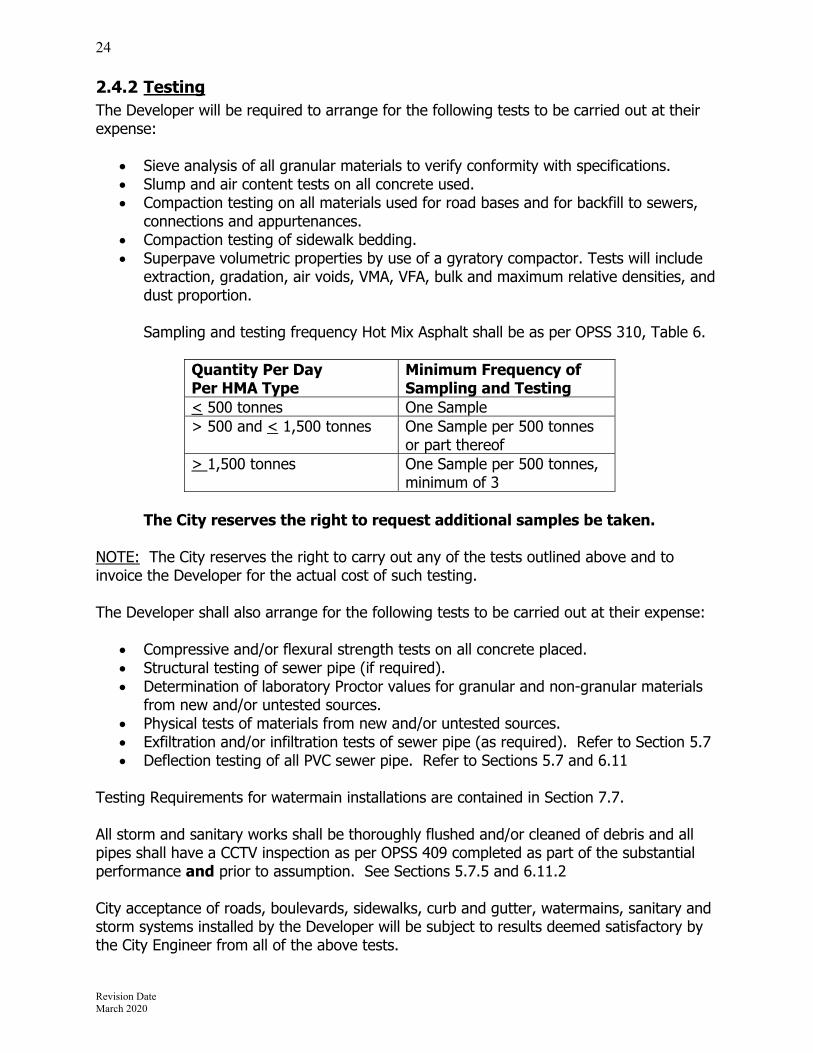
2.4.2 Testing The Developer will be required to arrange for the following tests to be carried out at their expense:
Sieve analysis of all granular materials to verify conformity with specifications. Slump and air content tests on all concrete used. Compaction testing on all materials used for road bases and for backfill to sewers,
connections and appurtenances. Compaction testing of sidewalk bedding. Superpave volumetric properties by use of a gyratory compactor. Tests will include
extraction, gradation, air voids, VMA, VFA, bulk and maximum relative densities, and dust proportion. Sampling and testing frequency Hot Mix Asphalt shall be as per OPSS 310, Table 6.
Quantity Per Day Per HMA Type
Minimum Frequency of Sampling and Testing
< 500 tonnes One Sample> 500 and < 1,500 tonnes One Sample per 500 tonnes
or part thereof > 1,500 tonnes One Sample per 500 tonnes,
minimum of 3
The City reserves the right to request additional samples be taken. NOTE: The City reserves the right to carry out any of the tests outlined above and to invoice the Developer for the actual cost of such testing. The Developer shall also arrange for the following tests to be carried out at their expense:
Compressive and/or flexural strength tests on all concrete placed. Structural testing of sewer pipe (if required). Determination of laboratory Proctor values for granular and non-granular materials
from new and/or untested sources. Physical tests of materials from new and/or untested sources. Exfiltration and/or infiltration tests of sewer pipe (as required). Refer to Section 5.7 Deflection testing of all PVC sewer pipe. Refer to Sections 5.7 and 6.11
Testing Requirements for watermain installations are contained in Section 7.7. All storm and sanitary works shall be thoroughly flushed and/or cleaned of debris and all pipes shall have a CCTV inspection as per OPSS 409 completed as part of the substantial performance and prior to assumption. See Sections 5.7.5 and 6.11.2 City acceptance of roads, boulevards, sidewalks, curb and gutter, watermains, sanitary and storm systems installed by the Developer will be subject to results deemed satisfactory by the City Engineer from all of the above tests.

Revision Date March 2020
25
2.5 Construction In addition to the requirements detailed elsewhere in this document, the following requirements apply:
No natural watercourses shall be blocked, abandoned or otherwise altered during the course of construction in the development unless approved by the City Engineer.
All new sanitary sewer systems shall be isolated from the City’s sanitary system. A maintenance hole shall be installed at the property line, with the sanitary sewer connection to the existing system plugged at that maintenance hole. The plug shall be a locked cap on the sanitary pipe inside the maintenance hole or other method approved by the City Engineer. The plug(s) shall remain in place until removal is authorized, in writing, by the City Engineer. The removal of the plug must be witnessed by City staff. In addition, this sanitary maintenance hole shall have a sump. The sump shall be cleaned of all debris and sediments as required. Benching shall be installed in the maintenance hole prior to assumption, when authorized by the City Engineer.
No surface coat asphalt pavement shall be constructed until after all underground services have been completed for at least one year. All curb and gutter or sidewalk that have been installed before this one year period is complete, must be inspected after the completion of the one year waiting period. After any deficiencies have been rectified, the City will issue the Certificate of Completion for those works and the maintenance period may begin. It should be noted that no sidewalk will be accepted for maintenance unless the City deems that there is sufficient continuous sidewalk ready for maintenance.
All ductwork for utility crossings must be completed and compacted prior to asphalt installation.
The Developer will be required to erect signs stating "Private Road - Travel at Your Own Risk" at the entrances to the development pending completion and acceptance of the permanent road by the City. See Std. Dwg. 39.
2.5.1 Backfill Material Trench backfill for all works shall be as recommended in the project geotechnical report. Minimum guidelines are as follows:
2.5.1.1 Greenfield Development The trench above the required bedding and cover shall be backfilled with approved
native material excavated from the trench or obtained elsewhere on the project, and shall be placed in layers not exceeding 300mm, and shall be compacted to 98% Standard Proctor Density.
Where approved native material is not suitable in the sole opinion of the Contract Administrator, and there is no approved native surplus material from other sections of the work, the Contract Administrator may order that the trench be wholly or partially backfilled with imported materials. In that case, backfill above cover material to 1.0 metres below road subgrade shall be Type 1 Granular B compacted to 100% Standard Proctor Density, and Type 1 modified Granular ‘B’ compacted to 100% Standard Proctor Density to the underside of the subgrade.

Revision Date March 2020
26
2.5.1.2 Reconstruction Trench backfill for reconstruction of existing City streets shall be as per Section
2.5.1.1. Trench backfill for road cuts and restoration of existing City streets, where full
reconstruction is not taking place, shall be as per City Std. Dwg. #40
2.5.1.3 Additional Considerations Between December 1 and April 30, unless prior approval to use select native
material is requested, in writing, from the City Engineer, all underground construction will require complete Granular 'B' backfill in the trenches. Backfilling with acceptable native material will be permitted in boulevards only during that time. The use of special equipment will be necessary in order to provide the required degree of compaction.
Where granular backfill is approved in place of native material, the City may require the installation of clay collars and/or other measures as appropriate to prevent excessive infiltration within the backfill
Whenever it is necessary to cut through an existing municipal road, the backfill within the travelled portion of the road shall be modified Granular ‘B’ material, as per Standard Dwg #40.
2.6 Acceptance of Works The City will grant Preliminary or Final Acceptance of the works based upon three (3) stages of construction; and when the development is phased, within the whole of each phase as approved by the City. Stages of construction are as follows:
Stage 1 – consists of all underground works including storm sewers, sanitary sewers, watermains, stormwater management facilities (excluding landscaping) and the completion of Granular ‘B’ road base and a portion of the Granular ‘A’ for riding surface. The completion and acceptance of this stage is required prior to the issuance of building permits.
Stage 2 – services shall include the balance of the road works including granular, curbs and gutter, base asphalt, grading of boulevard areas, installation of street and traffic signs, conduits, piping and facilities for the completion of electrical servicing, street lighting and other utilities such as gas, telephone and cable T.V.
Stage 3- services including the final coat of asphalt, sidewalks, topsoil and sodding, stormwater management facility landscaping, driveway ramps, fencing and any other requirements of this agreement.
2.6.1 Servicing (Excluding Stormwater Management Facilities)
2.6.1.1 Preliminary Acceptance When all the services in any stage of servicing are completed and cleaned to the satisfaction of the Consultant, the Consultant shall advise the City Engineer, in writing, that the work is completed in accordance with the approved plans and specifications as per the Subdivision Agreement and shall request an inspection by the City. The City shall carry out their inspections in the company of the Consultant and shall provide a deficiency list stating any items that require rectification. As soon as the deficiency list has been discharged, a

Revision Date March 2020
27
Certificate of Preliminary Acceptance will be issued to the Developer stating the date for the commencement of the maintenance period. The Performance Securities required by the Subdivision Agreement may be reduced as allowed upon receipt of:
The maintenance securities required by the Subdivision Agreement; The required test results; and As-Constructed information for stormwater management facilities and underground
works (Stage 1). As-Constructed Information for Underground Works Before building permits are requested in a new subdivision, a plan must be sent to the Engineering Division showing the elevation and location of all sanitary and storm service connections and the location of all water service connections at the front lot line of all properties. The location of the services must be tied into one of the lot corner bars. Where the lot line is along a curve, the ties can be along the chord between the two corner bars. As-Constructed Information for Stormwater Management Facilities Before building permits are requested in a new subdivision, an as-constructed topographic survey and engineering plans of the stormwater facility must be sent to the Engineering Division along with the calculations to verify the following:
Permanent pool volume Active storage volume Location and height of berms Location, invert elevations and size of pipes, inlets and orifices for outfall structure
The developer’s consultant shall certify that the as-constructed facility has been built in accordance with the engineering plans and design report.
2.6.1.2 Final Acceptance Near the end of the maintenance period, the services in each stage of construction shall be re-inspected by the Consultant and all deficiencies found shall be corrected. When the Consultant is satisfied that the work is complete and acceptable, they shall advise the City, in writing, and request a final inspection by the Engineering Division. When all work is completed to the satisfaction of the City and the City has received the Completion Certificate from the Consultant certifying that the works of each phase of the subdivision have been constructed and installed in accordance with the Subdivision Agreement and according to City specifications, standards and requirements, the Engineering Division will establish the date for Final Acceptance.

Revision Date March 2020
28
2.6.2 Stormwater Management Facilities In order for the City to accept and eventually assume the stormwater facility, the following requirements must be undertaken and completed to the satisfaction of the City.
2.6.2.1 Preliminary Acceptance – Stormwater Management Facilities When all the components of the stormwater management system are completed to the satisfaction of the Consultant, they shall advise the City Engineer, in writing, that the work is completed in accordance with the approved plans and specifications as per the Subdivision Agreement and shall request an inspection by the City. The City shall carry out their inspections in the company of the Consultant and shall provide a deficiency list stating any items that require rectification. Preliminary Acceptance will be granted upon the deficiency list being discharged, the completion of one calendar year of monitoring and testing as specified below, and certification from the Consultant that the stormwater management system and components are operating as designed. A Certificate of Preliminary Acceptance will be issued to the Developer stating the date for the commencement of the two year maintenance period. The Performance Securities required by the Subdivision Agreement may be reduced as allowed upon receipt of:
The maintenance securities required by the Subdivision Agreement; The required test results.
2.6.2.2 Quality Performance Monitoring and Sediment Removal – Wet Pond / Wetland Facilities
After grading of the facility is completed, the consultant shall complete a topographic survey of the facility to determine the elevations prior to the facility being operational. (See 2.6.1.1) The City requires that the survey work be completed in a dry condition. After the facility has been graded and inlet/outlet structures are in place, the consultant shall monitor forebay sediment levels on a monthly basis (April 1 to November 30) and main cell sediment levels on an annual basis until assumption by the City. Sediments shall be removed from the forebay on an annual basis, unless the consultant demonstrates that the accumulated sediment volume is less than 25% of the forebay permanent pool volume. To estimate the volume of forebay sediments, at least five uniformly distributed measurements of sediment depth shall be taken within the forebay. Sediments shall be removed from the main cell when the accumulated sediment volume is greater than 25% of the main cell permanent pool volume. The consultant shall estimate the volume of main cell sediments using at least five measurements of sediment depth along a mid section along the length of the facility. A secchi disk shall be used to estimate the sediment levels in a wet condition. A metric staff gauge shall be installed adjacent to the storm sewer inlet headwall so that the zero reading is at the permanent pool elevation. Outlet structures shall be inspected on a monthly basis to ensure that perforated riser inlets are not blocked due to sediments or debris. The consultant shall provide monthly inspection reports to the City along with instructions to the site contractor for any remedial work. This inspection shall be undertaken in dry weather conditions, at least 72 hours after any rainfall event. The

Revision Date March 2020
29
monthly reports shall include a staff gauge reading to determine any fluctuations in the permanent pool elevation. On a yearly basis between April 1 to November 30, at least five water samples shall be taken at the outfall from all facilities to assess the Total Suspended Solid (TSS) concentrations in mg/l. The samples shall be taken within 24 hours after a significant rainfall event. The samples shall be submitted to an accredited laboratory for analysis. The laboratory results for TSS concentrations shall be submitted to the City to access if the facility is releasing excessive sediment levels. Samples shall be taken for the period from substantial completion to assumption of the facility.
2.6.2.3 Quality Performance Monitoring and Sediment Removal – Dry Pond Facilities
After grading of the facility is completed, the consultant shall complete a topographic survey of the facility to determine the elevations prior to the facility being operational. (See 2.6.1.1) The City requires that the survey work be completed in a dry condition. After the facility has been graded and inlet/outlet structures are in place, the consultant shall monitor forebay and/or oil and grit separator sediment levels on a monthly basis (April 1 to November 30) and main cell sediment levels on an annual basis until assumption by the City. Sediments shall be removed annually, unless the consultant demonstrates that the accumulated sediment volume is less than 25% of the forebay permanent pool volume. To estimate the volume of forebay sediments, at least five uniformly distributed measurements of sediment depth shall be taken within the forebay. Outlet structures shall be inspected on a monthly basis to ensure that all inlets are not blocked due to sediments or debris. The consultant shall provide monthly inspection reports to the City along with instructions to the site contractor for any remedial work. This inspection shall be undertaken in dry weather conditions, at least 72 hours after any rainfall event, On a yearly basis between April 1 to November 30, at least five water samples shall be taken at the outfall from all facilities to assess the Total Suspended Solid (TSS) concentrations in mg/l. The samples shall be taken within 24 hours after a significant rainfall event. The samples shall be submitted to an accredited laboratory for analysis. The laboratory results for TSS concentrations shall be submitted to the City to access if the facility is releasing excessive sediment levels. Samples shall be taken for the period from substantial completion to assumption of the facility.
2.6.2.4 Quality Performance Monitoring and Sediment Removal – Other Facilities
The City will provide requirements to the Developer during the design and approval process, when appropriate.

Revision Date March 2020
30
2.6.2.5 Final Acceptance – Stormwater Management Facilities Near the end of the maintenance period, the stormwater management components shall be re-inspected by the Consultant and all deficiencies found shall be corrected. When the Consultant is satisfied that the work is complete and acceptable, they shall advise the City, in writing, and request a final inspection by the Engineering Division. When all work is completed to the satisfaction of the City, the Consultant shall provide:
a report summarizing the quality monitoring and test results, a Completion Certificate certifying that the works have been constructed, installed,
and are operating in accordance with the Subdivision Agreement and according to City specifications, standards and requirements.
Upon receipt of the above, the Engineering Division will establish the date for Final Acceptance.
2.6.3 Assumption After Final Acceptance has been granted for all servicing, including stormwater management, a report will be forwarded to Council recommending Assumption of the subdivision and the release of all remaining securities upon the completion of the following requirements:
The Developer shall have discharged all of their obligations as set out in the Subdivision or Servicing Agreement with the City.
The Developer shall furnish the City Engineer with a Statutory Declaration to the effect that the Developer has paid all accounts that are payable in connection with the installation and maintenance of such works and that there are no outstanding claims relating thereto.
The Developer shall register conveyance of all easements, park properties, walkways, etc. in favour of the City and shall provide the City Clerk with duplicate registered copies thereof.
The stormwater management facility will be drained and all sediments shall be removed from the forebay and main cell. A second topographic survey shall be completed after all sediment removal. This topographic survey shall be submitted to the City, along with a comparative analysis to the survey taken after substantial completion. The results should verify that all sediments have been removed from the facility.
The Developer shall provide all record drawings as specified in Section 2.7.
2.7 Record Drawings
2.7.1 General The Consultant shall maintain all notes and records required to confirm the services are built to the design specifications and drawings and to prepare record drawings. The record drawings constitute all original engineering drawings amended to incorporate the construction changes and variances in order to provide accurate information on the works as installed in the development.

Revision Date March 2020
31
Lots and Blocks are to be numbered according to the Registered Plan and the municipal street address as provided by the City is to be shown. The City will also provide unique numbers to identify all maintenance holes. Adjacent to the title block on the general servicing plan shall appear the name of the Contractor and Sub-Contractors together with the commencement and completion dates of each section of work. The City performs a spot check of elevations and locations. If the City finds major differences, the drawings will be returned to the Consultant for correction. All cost incurred by City Forces to complete the work will be borne by the developer. Upon completion of all construction work and the record drawing revisions, original drawings shall be submitted to the City for their permanent records. Drawings shall be supplied in a digital format in addition to paper copies, and shall conform to UTM NAD 83 Zone 17 and the City’s most recent requirements and AutoCAD standards. In addition, the required plot setting files shall be provided for all digital drawings.
2.7.2 “As-constructed” Field Survey The “as-constructed” revisions shall be based on a final survey of all the subdivision services and the Consultant’s construction records. The final survey shall include a final verification of the following: Location, rim and invert elevations of all sewer maintenance holes; Distances between all sewer maintenance holes; Location and rim elevation of all roadway catchbasins; Location, rim and invert elevations for all rear yard and lot catchbasins; Location and ties to all valve boxes, chambers, hydrants and other watermain
appurtenances; Location of all street lights and appurtenances; Location of all transformers, concrete encased duct road crossings; Location of all above ground utility boxes; Road centreline elevations; Geodetic site benchmarks; and Location of all service connections to all lots and blocks and location of connection from
the nearest downstream maintenance hole, (i.e. 0+023).
2.7.3 Drawing Revisions The original drawings shall be revised to incorporate all changes and variances found during the field survey and to provide ties and additional information to readily locate all underground services. The “record drawing” revision note shall be placed on all drawings in the revision block. The information on the record drawings may be checked by the City at any time up to two years after final acceptance of the subdivision. If any discrepancies are found, then the drawings shall be returned to the Consultant for rechecking and further revision. The Consultant shall be required to explain in writing any major difference between the design and the “as-constructed” data and to provide verification that the alteration does not adversely affect the function of the subdivision services.

Revision Date March 2020
32
Specific requirements for Storm System, Sanitary Sewers, Watermains and Roadways are noted in the following sections. Storm Sewers All actual storm system invert elevations shall be indicated on the “as-constructed” drawings. If the difference is greater than 150mm from the design vertical alignment, affected portions of the sewer or overland drainage route shall be redrawn in profile. Any maintenance hole that differs from the proposed horizontal location by more than 1.50m shall be redrawn in both plan and profile. In addition, the following shall be indicated on the “as-constructed” drawings:
Pipe/culvert size, grade, type, class/gauge, bedding, length; Chainage from MH along main to service tees; and Dimensions from lot corners and invert elevations at street line for service laterals.
If as-constructed grade of sewer differs by more than 10% of the design grade, the Consultant shall submit hydraulic calculations. Q actual and Q design will also be required on as-constructed sheets. Sanitary Sewers All actual sanitary sewer invert elevations shall be indicated on the “as-constructed” drawings. If the difference is greater than 150mm from the design vertical alignment, affected portions of the sewer shall be redrawn in profile. Any maintenance hole that differs from proposed horizontal location by more than 1.5m shall be redrawn in both plan and profile. In addition the following shall be indicated on the “as-constructed” drawings:
Pipe size, grade, type, class, bedding, length; Chainage from MH along to service tees; Dimensions from lot corners and invert elevations at street line for service laterals.
Watermains All actual watermain obvert elevations at 50m intervals shall be indicated on the “as-constructed’ drawings. If the difference is greater than 150mm from design vertical alignment, affected portions of the watermain shall be redrawn in profile. If horizontal alignment changes exceed 1.5m the affected portions of the watermain shall be redrawn in plan. In addition the following shall be indicated on the “as-constructed” drawings:
Pipe size, type, class, bedding; Swing-ties to all main appurtenances (valves, bends, tees, etc); Chainage from appurtenance along main to main stops; and Dimensions from lot corners and elevations for service laterals.
Revision Date March 2020
33
Roadways All actual roadway centre line elevation, at a maximum 20m interval, shall be indicated on the “as-constructed” drawings. Gutter elevations shall be indicated for cul-de-sacs and intersections to show drainage into storm system. If horizontal road alignment changes more than 1.5m or vertical geometry changes greater than 150mm the plan and/or profile shall be redrawn as appropriate. In addition the following shall be indicated on the “as-constructed” drawings:
Driveways, lay-byes, curb depressions; Road signage; Street lights; Utility boxes and transformers; Utility road crossings and extent of concrete encased ducting Mailboxes; and Boulevard trees.
Stormwater Management Facilities Refer to Sections 2.6.1.1 and 2.6.2.1
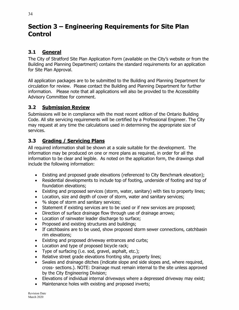
Revision Date March 2020
34
Section 3 – Engineering Requirements for Site Plan Control
3.1 General The City of Stratford Site Plan Application Form (available on the City’s website or from the Building and Planning Department) contains the standard requirements for an application for Site Plan Approval. All application packages are to be submitted to the Building and Planning Department for circulation for review. Please contact the Building and Planning Department for further information. Please note that all applications will also be provided to the Accessibility Advisory Committee for comment.
3.2 Submission Review Submissions will be in compliance with the most recent edition of the Ontario Building Code. All site servicing requirements will be certified by a Professional Engineer. The City may request at any time the calculations used in determining the appropriate size of services.
3.3 Grading / Servicing Plans All required information shall be shown at a scale suitable for the development. The information may be produced on one or more plans as required, in order for all the information to be clear and legible. As noted on the application form, the drawings shall include the following information:
Existing and proposed grade elevations (referenced to City Benchmark elevation); Residential developments to include top of footing, underside of footing and top of
foundation elevations; Existing and proposed services (storm, water, sanitary) with ties to property lines; Location, size and depth of cover of storm, water and sanitary services; % slope of storm and sanitary services; Statement if existing services are to be used or if new services are proposed; Direction of surface drainage flow through use of drainage arrows; Location of rainwater leader discharge to surface; Proposed and existing structures and buildings; If catchbasins are to be used, show proposed storm sewer connections, catchbasin
rim elevations; Existing and proposed driveway entrances and curbs; Location and type of proposed bicycle rack; Type of surfacing (i.e. sod, gravel, asphalt, etc.); Relative street grade elevations fronting site, property lines; Swales and drainage ditches (indicate slope and side slopes and, where required,
cross- sections.). NOTE: Drainage must remain internal to the site unless approved by the City Engineering Division;
Elevations of individual internal driveways where a depressed driveway may exist; Maintenance holes with existing and proposed inverts;

Revision Date March 2020
35
Location of closest fire hydrant(s) (existing and proposed); Location of existing and proposed siamese or standpipe connection; Hydro poles and transformers; Inverts of storm, sanitary and water laterals at point of connection; Location of existing and proposed easements and rights of way, road dedications /
widenings; Locations of any lands to be dedicated for public purposes; Site lighting.
In addition, the following information is required on the plans:
The details for all proposed stormwater management features shall be shown, including the limits of the maximum storage volume for the 5, 100, and 250 year return period storms.
Breakdown of water and sanitary service sizing determination as per the OBC. Proposed erosion and sediment control measures and notes – refer to Section 6.1
for guidelines. Construction notes for all works to be done, including restoration. Location of proposed hydro connection to the existing hydro plant. Said connection
shall be noted as underground or above ground.
3.4 Stormwater Management Requirements Refer to Section 6.12 for the appropriate stormwater management requirements.
3.5 Landscaping Plans All developments completed under Site Plan Control shall utilize and implement the City of Stratford Landscape Guidelines available on the City website.
3.6 Work Proposed on City Roadways All works proposed within the right-of-way of any City street must be co-ordinated with the Engineering Division. All contractors must obtain a Road Occupancy Permit prior to commencing work within the right-of-way. Responsibility for the construction of any underground servicing will be determined by the City on a case by case basis. In addition to those deposits required by the Site Plan Agreement, the developer will be required to submit deposits (amount determined by the Engineering Division) in the form of a certified cheque or cash to provide for the works being done on the roadway.
3.7 Connection to City Sanitary Sewer System The requirements pertaining to sanitary maintenance holes contained in Section 2.5 may be imposed, at the discretion of the City Engineer. All commercial and industrial properties shall have an inspection maintenance hole for the private sanitary service installed at the property line.

Revision Date March 2020
36
3.8 Inspection and Certification of Works The Professional Engineer responsible for determining the degree of inspection and testing required for certification of underground service installations as mandated by the Ontario Building Code, Division, C, Part 1, ,Section 1.2.2.2, General Review. In addition to the requirements contained within the Site Plan Agreement, any certification of a stormwater management facility must be accompanied by an operation and maintenance plan and an as-constructed plan completed by an O.L.S. or Engineer.
3.9 As-Constructed Plans The Consultant shall maintain all notes and records required to confirm the site servicing and grading are constructed to the design specifications and drawings, in addition to record drawings preparation. The record drawings shall provide an accurate representation of the finished site and constitute original site plan grading and servicing drawings amended to incorporate the construction changes and variances. Upon completion of all construction work and the record drawing revisions, paper and digital format drawings shall be submitted to the City for their permanent records. Drawings supplied in a digital format shall conform to UTM NAD 83 Zone 17, the City’s most recent requirements and AutoCAD standards. The “as-constructed” revisions shall be based on a final survey of the development and the Consultant’s construction records. The final survey shall include a final verification of the following: Location, rim and invert elevations of all sewer maintenance holes and catchbasins; Location and method of capped and plugged pipe; Pipe/culvert size, length, slope; Dimensions from lot corners and invert elevations at street line for service laterals Driveways, lay-byes, curb depressions; Site benchmarks; Sufficient finished ground elevations to confirm all site grading and swales were
constructed as designed; Location, invert elevations and size of orifices; Identification of all quality control structures; and Location and elevation of all above ground features proposed on the site plan including,
but not limited to, hydrants, curbing, sidewalks, signage, stairs, retaining walls, poles, trees.
The Consultant shall be required to explain in writing any major difference between the design and the “as-constructed” data and to provide verification that the alteration does not adversely affect the function of the site services or stormwater management system.

Revision Date March 2020
37
Section 4 – Roadways
4.1 General All design and construction of roads, boulevards and sidewalks shall be carried out in complete conformity with this manual. All geometric design shall conform to the Transportation Association of Canada Geometric Design Guide for Canadian Roads (TAC). The use of Supplementary Drawings and Special Provisions prepared by the Consultant will be permitted, provided approval of the City Engineer is first obtained. Where any portion of work is not covered by the City Standards, the appropriate Ontario Provincial Standard Specification shall apply. Design standards for reconstruction projects shall be reviewed and approved on a site specific basis. The street classification shall be determined by the City Engineer. The Developer will be required to convey gratuitously for road purposes, a parcel of the appropriate right-of-way width to accommodate the designated road classification.
4.2 Geometric Design Elements The following design elements apply to all roads in new developments. Reconstruction projects will attempt to match these elements as much as possible while matching into existing features. Geometric Detail Local Collector Arterial 2 lane 4 lane
Min. R.O.W. (metres) 20 23 30 30
Design Speed (km/hr) 60 60 70 70 Min. Safe Stopping Distance (metres) 65 65 85 85
Min. Visibility Curves in Sag (K Values) 12 18 18 18
Min. Visibility Curves on Crests (K Values) 8 15 15 15
Pavement Width (face to face of curbs) (metres) 8.5 10.4 14 14
Pavement Crossfall (%) 2 2 2 2
Minimum Grade (%) 0.5 0.5 0.5 0.5
Maximum Grade (%) 8 6 6 6 Max. Grade For Through Roads At Intersections 3.5 3.0 3.0 2.0
Max. Grade At Stop Roads At Intersections 2.0 1.5 1.5 1.0
Intersection Angle (degrees) 70-90 85-90 85-90 85-90 Minimum Tangent Length Between Reverse Curves (metres)
30 60 60 130

Revision Date March 2020
38
4.2.1 Vertical Curves All points of grade change in excess of one percent shall be designed with vertical curves. The minimum visibility curves to be used are outlined in the geometric details for each roadway classification. The minimum tangent length of any road grade shall be 9 metres.
4.2.2 Backfall at Intersecting Streets At all street intersections the normal crossfall of the major street shall not be interrupted by the crown line of the minor street. One to two percent backfall shall be provided on the minor street at all street intersections. This backfall shall continue to the end of the curb return radii to facilitate proper drainage of the intersection. Overland flow routing of storm drainage through the intersection must be maintained.
4.2.3 Centreline Radii
4.2.3.1 Arterials Centreline horizontal curves for arterial roads shall be derived from Table C3-3 of the Geometric Design Standards for Ontario Highways.
4.2.3.2 Collector and Local Streets for New Construction Minimum centreline radii for horizontal curves are:
Arterial roads 195m Collector roads 115m Local roads 85m
Local Streets with bends of approximately 90 degrees are to have a minimum inside street-line radius of 9.0m or as required by the City Engineer. Bends of 90 degrees are only permitted on local streets.
4.2.3.3 Reconstruction Projects All projects requiring the reconstruction of existing roads are to have the centreline horizontal alignments reviewed by the City Engineer on a site-specific basis.
4.2.4 Radii for Curb & Gutter
4.2.4.1 Intersections Intersection Radii for curb and gutter should be measured at face of curb. The following chart identifies the required minimum radii: To:
From
:
Arterial Collector Local Arterial 15m 12m 12m Collector 12m 12m 9m Local 12m 9m 7.5m
Industrial 15m 15m 15m

Revision Date March 2020
39
4.2.4.2 Bus Routes All intersections that have, or are proposed to be, bus routes are to have a
minimum 12.0m radii regardless of the classification of the road.
4.2.4.3 Cul-de-Sacs The minimum required radii of curvature for curb and gutters for a residential and industrial cul-de-sac are follows:
Radius to curb in cul-de-sac 15.0 m minimum Boulevard width in cul-de-sac 3.0 m minimum Centre island radius 6.0 m minimum
4.2.5 Daylighting Requirements at Intersections Daylighting at all intersection quadrants shall be included in the road allowances as detailed in the applicable Secondary Plan, Class EA, or transportation impact study. If the intersection or its daylighting is not included in the former, the following requirements are to be met:
At the intersection of a local street with an arterial, the daylighting triangle shall have a dimension of 10.0m along the frontage of each street.
At the intersection of a collector with a collector or arterial, the daylighting triangle shall have a dimension of 10.0m along the frontage of each street.
At the intersection of an arterial with an arterial, the daylighting triangle shall have a dimension of 10.0m along the frontage of each street.
The above daylighting shall be included on the proposed plan for Registration (M Plan) and on all engineering drawings.
4.2.6 Cul-de-Sac and Bulbs Permanent cul-de-sacs shall be constructed in accordance with the details provided on Standard Dwg. 4. Minimum gutter grades of one percent shall be maintained along the flow line of the gutters around the cul-de-sac. The design of the road grade shall be such that the drainage is directed away from the end of the cul-de-sac and towards the beginning of the bulb area where catchbasins are to be located.
4.2.7 Temporary Turning Circles Temporary turning circles will be considered whenever a road is to be continued in the future in a phased Plan of Subdivision. The minimum paved radius for temporary turning circles shall be 15.00m and as shown on Standard Dwg. 5.
4.2.8 Roundabouts Requirements and standards for roundabouts shall be determined during consultation between the City and its consultant during the pre-consultation process.
4.2.9 Turning Lanes Requirements and standards for turning lanes shall be determined upon the request of the Engineering Division during the site plan review process, subdivision review, or the design or redesign of a roadway.

Revision Date March 2020
40
Length of the tapered and parallel portions of the turn lane shall be determined using Table E9-1 of the Geometric Design Standards for Ontario Highways. Additional width may be requested to accommodate bike lanes. Storage queuing requirements should be determined by a traffic study. Storage distance starts 15m from the centreline of the cross street or at the stop bar.
4.2.10 Utilities The location of utilities within the road allowance shall be as detailed on the City of Stratford Std. Dwgs. All utility wiring is to be housed underground or direct buried. Hydro transformers are to be housed in suitable enclosures and mounted on transformer pads installed at the final elevation of the adjacent ground. Telephone and Cable T.V. junction boxes may be mounted at the surface in approved standard enclosures. In new developments, telephone, communications and cable TV cable shall be placed in a common trench with hydro cable. Exceptions to this requirement must be approved in writing by the City Engineer. All telephone and cable boxes shall be located at property line. All transformers must be located such that there is a minimum of 1.0m clearance from the face of the transformer to the curb line, and a minimum of 0.5m clearance from any sidewalk. Bollards may be required to protect the transformer. No above ground plant shall be located within the extension of daylight triangles at intersections. All utility companies are required to obtain a Municipal Consent for the installation of their plant on existing roads. Specific requirements are contained within the Municipal Consent Agreement for each utility. When new infrastructure is installed to replace existing plant, all abandoned plant must be removed.
4.3 Special Road Designs Special road designs, which are not covered by City standards, shall be in accordance with the most recent provision of the geometric design standards manual and urban street geometrics, as adopted by the Municipal Engineers Associates (i.e. Special design may be required in high density residential, commercial and industrial areas).
4.4 Pavement Design The Proponent shall retain a qualified geotechnical consultant to perform all tests necessary to confirm the subgrade strength. The City of Stratford will identify which residential road segments will be subjected to higher average annual daily truck traffic (AADTT) and part of a current or future bus route. The geotechnical investigation for development shall be submitted to the City for review. In no case will a pavement design with less than the minimum requirements be considered acceptable.

Commerical Provincial Highways Industrial
Minor Major (with Bus Route)
Arterial (with Bus Route) Downtown Truck Route
<50 50 ‐ 100 150 ‐ 350 350 ‐ 500 1000 ‐ 1500 100 ‐ 450
Notes:. All materials are based on current OPS Specifications. Subgrade levels are based on three common subgrade materials in Ontario. Areas with low plasticity clay and low plasticity silt subgrade will be frost susceptible.. Frost Penetration: 60% FD = 840 mm, 40% FD = 560 mm. *Granular subbase thickness can be reduced by ~40% if Granular B Type II or crushed concrete is used in lieu of Granular B Type I if not required for frost penetration
Superpave 12.5 Surface mix for use on Traffic Category B roads
Residential
Traffic Category B40 mm SP 12.5 ‐ PGAC 58H‐28100 mm SP 19 ‐ PGAC 58S‐28
150 mm Granular Base*475/750 mm Granular Subbase
Traffic Category B50 mm SP 12.5 ‐ PGAC 58S‐2870 mm SP 19 ‐ PGAC 58S‐28
150 mm Granular Base650 mm Granular Subbase
Traffic Category B80 mm SP 12.5 ‐ PGAC 58S‐28
150 mm Granular Base425 mm Granular Subbase
Traffic Category B40 mm SP 12.5 ‐ PGAC 58H‐28100 mm SP 19 ‐ PGAC 58S‐28
150 mm Granular Base250 mm Granular Subbase
AADTT
HMA45 MPa
Subgrade
Stren
gth
15 Mpa
HMA
HMA30 MPa
Traffic Category B50 mm SP 12.5 ‐ PGAC 58S‐2870 mm SP 19 ‐ PGAC 58S‐28
150 mm Granular Base200 mm Granular Subbase
Traffic Category B80 mm SP 12.5 ‐ PGAC 58S‐28
150 mm Granular Base150 mm Granular Subbase
Traffic Category B40 mm SP 12.5 ‐ PGAC 58H‐28100 mm SP 19 ‐ PGAC 58S‐28
150 mm Granular Base425 mm Granular Subbase
Traffic Category B50 mm SP 12.5 ‐ PGAC 58S‐2870 mm SP 19 ‐ PGAC 58S‐28
150 mm Granular Base350 mm Granular Subbase
Traffic Category B80 mm SP 12.5 ‐ PGAC 58S‐28
150 mm Granular Base250 mm Granular Subbase
Traffic Category C40 mm SP 12.5 FC1 ‐ PGAC 58H‐28
50 mm SP 19 ‐ PGAC 58H‐2860 mm SP 19 ‐ PGAC 58S‐28
150 mm Granular Base475 mm Granular Subbase
Traffic Category C40 mm SP 12.5 FC1 ‐ PGAC 58H‐28
50 mm SP 19 ‐ PGAC 58H‐2860 mm SP 19 ‐ PGAC 58S‐28
150 mm Granular Base500/825 mm Granular Subbase
Traffic Category D45 mm SP 12.5 FC2 ‐ PGAC 58H‐28
65 mm SP 19 ‐ PGAC 58H‐2870 mm SP 19 ‐ PGAC 58S‐28
175 mm Granular Base350 mm Granular Subbase
Traffic Category D45 mm SP 12.5 FC2 ‐ PGAC 58H‐28
65 mm SP 19 ‐ PGAC 58H‐2870 mm SP 19 ‐ PGAC 58S‐28
175 mm Granular Base550 mm Granular Subbase
Traffic Category D45 mm SP 12.5 FC2 ‐ PGAC 58H‐28
65 mm SP 19 ‐ PGAC 58H‐2870 mm SP 19 ‐ PGAC 58S‐28
175 mm Granular Base*575/950 mm Granular Subbase
City of Stratford Minimum Pavement Design Thickness
Classification
Superpave 19.0Superpave 12.5 FC2Superpave 12.5 FC1
Binder course for use on Traffic Category A, B, C, D, and E roadsSurface mix for use on Traffic Category D and E roadsSurface mix for use on Traffic Category C roads
Traffic Category C45 mm SP 12.5 ‐ PGAC 58H‐2850 mm SP 19 ‐ PGAC 58H‐2850 mm SP 19 ‐ PGAC 58S‐28
150 mm Granular Base275 mm Granular Subbase
Traffic Category C45 mm SP 12.5 ‐ PGAC 58H‐2850 mm SP 19 ‐ PGAC 58H‐2850 mm SP 19 ‐ PGAC 58S‐28
150 mm Granular Base425 mm Granular Subbase
Traffic Category C45 mm SP 12.5 ‐ PGAC 58H‐2850 mm SP 19 ‐ PGAC 58H‐2850 mm SP 19 ‐ PGAC 58S‐28
150 mm Granular Base*475/750 mm Granular Subbase
Traffic Category C40 mm SP 12.5 FC1 ‐ PGAC 58H‐28
50 mm SP 19 ‐ PGAC 58H‐2860 mm SP 19 ‐ PGAC 58S‐28
150 mm Granular Base300 mm Granular Subbase

Revision Date March 2020
42
Prior to placement of granular material, test results from the Proponents Geotechnical Consultant shall be provided to the City to prove compliance with OPSS. Prior to the placement of asphalt pavement, the Consultant must submit the asphalt pavement mix designs to the City for approval. Material specifications may be updated from time to time. Contact the Engineering Division prior to construction to ensure that the proper specifications are adhered to. The reconstruction of existing roads must have pavement widths and designs reviewed by the City on a site specific basis.
4.5 Construction Requirements
4.5.1 Clearing, Grubbing, and Area Rough Grading The road allowance shall be cleared of all trees and shrubs that are not to be retained, and of all other obstructions for such widths as are required for the proper installation of roads, services and other works. Rough grading shall be done to bring the travelled portion of the road to the necessary grade and in conformity with the cross-section shown on the drawings. The sub-grade must be properly shaped and compacted to 95 percent Standard Proctor Density or as noted in the applicable geotechnical report, prior to any application of granular base course materials. Rough grading of all lots and easements must be undertaken if cut or fill in excess of 400mm is required for proper drainage. In all cases, topsoil shall be stripped for the complete width of the road allowance and stockpiled at locations approved by the City.
4.5.2 Road Construction All road construction shall conform to applicable standards of the Ontario Provincial Standard Specifications (OPSS) and the Ontario Provincial Std. Dwgs (OPSD). The granular materials shall be spread in layers of 150mm maximum compacted depths, and each layer shall be thoroughly compacted. During and between construction seasons, the granular base shall be maintained suitable for vehicle and pedestrian traffic, including dust control by calcium chloride and renewed if required to the satisfaction of the City.
4.5.3 Road Subdrains In general, 150mm diameter subdrain will be required to run continuous along both sides of all roads with curb and gutter. It will be the responsibility of the proponent to justify deviation from this standard by submitting an appropriate Geotechnical Report from a recognized independent Soils Consultant with alternative recommendations. The subdrain material shall be HDPE corrugated perforated pipe with a minimum pipe stiffness of 210 kPa, and wrapped in filter cloth. As per OPSD 216.021, the first metre from the point of connection at the structure shall be non-perforated.

Revision Date March 2020
43
4.5.4 Requirements Prior to Surface Course Asphalt Approval to place top asphalt is required from the City Engineer. The placement of surface course asphalt shall not commence in any area until all of the following conditions are met:
A minimum period of one year has expired from the completion date for the placement of the base course asphalt;
100 percent of the dwellings have received Final Occupancy Permits or a maximum of three years has passed since the placement of base course asphalt;
All undeveloped lots are rough graded in accordance with approved grading plans; All services for multiple family, commercial, institutional or other blocks are installed; Maintenance hole and catchbasin frames have been raised; All sidewalk, curb and boulevard work is complete; The surface has been flushed and swept; A tack coat has been applied; The final sewer video(s) have been approved; The approval of the City Engineer is obtained in writing; All deficiencies and settlements have been repaired.
4.5.5 Tack Coat For lane paving, tack coat shall be applied using a self-propelled or tow-along pressure distributor capable of applying the product at the specified rate and in a continuous and uniform manner both longitudinally and transversely for the full lane width. The distributors shall be equipped with a volume-determining device of sufficient sensitivity to measure the quantity of tack coat dispensed, measurable to four or five litres. Tact coat shall be placed sufficiently ahead of the paving operation to allow for curing. Paving equipment shall not be permitted upon the tack coat until it has fully cured. The diluted emulsion shall be applied at the following rates:
0.20 litres / m2 to all new or milled pavement surfaces; 0.30 litres / m2 to any surface that has been left open to traffic over at least one
winter; and 0.45 litres / m2 to expanded asphalt surfaces or cold-in-place recycled surfaces.
The use of a hand held pressure wand is acceptable for tact coating only small areas, and irregularly shaped areas such as tapers.
4.5.6 Asphalt Paving Operations Material transfer devices are to be used for all roadway paving operations including surface and base courses, where 800 tonnes or more of asphalt is to be placed.
Where 800 tonnes of surface asphalt is to be placed, cold joints are to be pre-heated using a paver mounted infrared joint heater that achieves a joint temperature of 90 degrees C (+/- 10 degrees C) immediately ahead of the paver. Longitudinal joints are to be constructed in accordance with OPSS. 310. The width of subsequent courses shall be staggered to an offset of 150mm to 300mm so that longitudinal joints do not coincide. This shall also apply to the joint between through

Revision Date March 2020
44
lanes and speed change lanes and other similar longitudinal joints. The longitudinal joints in the surface course shall correspond to the demarcation between the driving lanes, speed change lanes, and tapers. During surface course paving, excess material shall not be cast onto the surface of the freshly laid mat. A 0.6m step joint to be provided at all transitions with existing asphalt per OPSD 509.010. The operational constraints of paving shall be as per OPSS 310
Paving shall not be carried out if the roadbed is frozen. The granular grade shall be free of standing water at the time of HMA placement. The surface of a pavement upon which HMA is to be placed shall be dry at the time
of HMA placement. An HMA course shall not be placed on a previously laid course until a minimum 4 hours have elapsed, following final compaction of the previous course, and the temperature of the previous course is 50°C or less.
Binder courses shall not be placed unless the air temperature at the surface of the road is a minimum of 2°C and rising.
Surface course, the air temperature at the surface of the road shall be at least 7 °C.
4.5.7 Other Requirements Road Cuts Whenever it is necessary to cut through an existing municipal road, the Contractor must obtain a Road Occupancy Permit from the Engineering Division. The placement and compaction of the backfill material and the restoration of the surface pavement shall be done in accordance with the standards and specifications in effect at that time. All backfill within the travelled portion of the road shall be modified Granular ‘B’ material, as per Standard Dwg #40. Road Closures or Detours Before making detours or obtaining road closures, permission is required from the Engineering Division. Where the road is not part of the municipal road system or affects adjoining municipalities, approval from and/or notification of the appropriate road authority will also be necessary. In all cases, the Contractor shall submit a Traffic Control Plan, in accordance with the requirements of MTO Book 7, a minimum of 48 hours prior to the proposed closure or detour. The Fire Department, Police Department, School Bus Companies and Ambulance Services must be notified by the Developer, the Contractor, or the City, as determined in each case. All work will be done in accordance with ordinances and By-laws of the City of Stratford.
4.5.8 Road Occupancy Permits – Scheduled for 2021 All construction activity (excavation, installation of plant, restoration, parking of construction vehicles, etc) within an existing City road allowance requires a Road Occupancy Permit. Refer to By-law xx-2021 for fees and specific information.

Revision Date March 2020
45
4.6 Curbs and Gutters New City streets shall be constructed with curb and gutter as per OPSD 600.040 (Barrier Curb with Standard Gutter) and OPSS 353. Concrete Barrier Curb as per OPSD 600.110 shall be used on islands in cul-de-sacs and medians on roads. Two-stage curb is not permitted. Curb termination as per OPSD 608.010 shall be used within temporary turning circles and dead end streets or intersections that abut or are adjacent to a future phase of a subdivision. Curb depressions are required at each intersection as per Standard Dwg # 8. Prior to final acceptance, all curb blemishes will be rectified by removing and replacing a minimum 1m section of curb or to the nearest joint (at the discretion of the City Engineer). A minimum of 300mm of Granular ‘A’ material compacted to 100% Standard Proctor Density will be required as a base for all curb replacements. Driveway depressions shall be formed in the curb according to the detail and location as per Section 4.10.3. If driveway locations cannot be determined at the time of pouring, a full section of curb and gutter shall be poured continuously. When the driveway location is determined, a driveway depression can be formed by cutting the back of the curb with a curb cutting machine providing the section to be cut is free from cracks and other defects. Curb cuts are subject to inspection by the City and if found to be unsatisfactory shall be replaced. All curb and gutter is to be complete prior to the placement of base asphalt to prevent saw cutting and patching. All curb and gutter is to be protected from damage from heavy equipment and vehicles until surface coat asphalt is installed.
4.7 Sidewalks and Walkways The location requirements of sidewalks in new subdivisions shall be confirmed with the City prior to commencing the detailed design. In general, sidewalks are required as outlined below:
Arterial and Collector Street both sides Local Street and Crescent one side Short Cul-de-sac (< 12 single family lots) no sidewalks
Where the development generates the need, in the opinion of the City, sidewalks may also be required on existing streets external to the Subdivision or streets where reverse frontage is proposed. This sidewalk will be installed at the cost of the developer. Concrete sidewalks shall be constructed as per Standard Dwgs #6 and #7, with a minimum width of 1.5 m and thickness of 140mm. Sidewalk thickness shall be increased for Commercial and Industrial driveways as per OPSD 310.010. The sidewalk shall be ramped to a curb depression to provide a handicap accessible ramp, including cast iron yellow

Revision Date March 2020
46
tactile warning plates by East Jordan Ironworks or an approved equivalent at all intersections and park areas, as detailed on Dwgs #8,#9 and #10. Walkways shall be constructed as required within the plan for the proper circulation of pedestrian traffic and shall be in accordance with the most recent requirements and specifications of the City. All walkways shall be contained within Blocks, a minimum of 3.0m wide, deeded to the City. Walkway Blocks may be located within larger service easements. Walkways shall have a minimum sidewalk width of 1.8 m and fencing constructed thereon. Refer to Dwgs. 31 and 41. Sidewalk requirements as part of the reconstruction of existing roads will be reviewed by the City on a site specific basis.
4.7.1 Rest Areas Consultation with the Accessibility Advisory Committee is required to evaluate opportunities to improve access and usability of sidewalks and walkways for all pedestrians, including people with disabilities. Placement and design of rest areas when constructing new or replacing existing sidewalks shall be determined on a case-by-case basis. Any rest areas shall conform to Dwg #43.
4.8 Bicycle Lanes and Multi-Use Trails In accordance with the Bike and Pedestrian Master Plan, the Developer shall provide for the construction of bicycle lanes or multi-use trails in a location agreed to with the City during the pre-consultation process. Multi-use trails shall be a minimum width of 3.0m, located as determined by the City, and constructed with 80mm of hot mix asphalt (40mm HL3 and 40mm HL8) over 225mm of Granular ‘A’(compacted). In low lying and wet soils conditions, woven geotextile Class II fos 75 – 150 (OPSS 1860) shall underlie the trail base. Excavation of trail shall be to firm bottom, removing all inorganic and deleterious materials. The City Engineer shall confirm the requirement for geotextile. Alternative materials must be submitted to the City for approval.
4.9 Bus Bays Upon the request of the City, the Developer shall include bus bays in the road design in locations agreed to during the pre-consultation process.
4.10 Driveway Entrances The developer is responsible for the grading, graveling and asphalt paving of all driveway entrances to the property line or, where sidewalks, to the edge closest to the curb. Driveway entrances shall not be constructed sooner than one year after completion of any underground services located under the driveway. Paving with alternative hard-surface materials is subject to approval of the City. The minimum clear distance between the edge of driveway and a utility structure or hydrant shall be 1.5m.

Revision Date March 2020
47
4.10.1 Minimum Driveway Design The minimum consolidated depth requirements for the granular base and asphalt in driveway shall be as follows: (a) Single Family Residential - Asphalt 50mm of HL3F hot mix asphalt - Granular 225mm (compacted) Granular ‘A’ (b) Commercial, Light Industrial and Apartments - Asphalt 40mm HL3 surface course 80mm HL8 base course - Granular Base 150mm Granular “A”
225mm Granular “B” (c) Heavy Industrial Driveways - Asphalt 40mm HL3 surface course
100mm HL8 base course - Granular Base 150mm Granular “A”
300mm Granular “B”
4.10.2 Driveway Grades The maximum permissible design grade for any driveway on private lands shall be 8.0 percent. The minimum grade for driveways shall be 1.0 percent. If the driveway provides the only paved pedestrian access to a building, the maximum grade shall be 5% in accordance with AODA.
4.10.3 Driveway Depressions Driveway entrances and curb cuts shall be in accordance with OPSD 350.010 and 351.010 subject to the maximum widths allowed by the City of Stratford Zoning By-Law.
4.11 Boulevards All boulevard areas are to be graded according to the details shown on the typical road cross- sections and to the satisfaction of the City. The grade of the boulevard is to be constant from the back of the curb to the sidewalk or property line and in no case will terracing be permitted. The final grade of the sod shall match and not exceed the finished grade of the top of the concrete curb and/or sidewalk. All debris and construction materials shall be removed from the boulevard area upon completion of the base course asphalt and shall be maintained in a clean state until the roadway section is completed. Clean weed free topsoil shall be placed on all boulevard areas that are to be sodded. The minimum depth of topsoil shall be 200mm. No. 1 Nursery Sod shall be used for all areas that are to be sodded.

Revision Date March 2020
48
4.11.1 Open Ditches Ditch side slopes shall not be steeper than 3:1 with a maximum depth of 1.2 metres unless otherwise approved by the City Engineer. The minimum depth of ditches shall be 150mm below the subgrade of the road. Culverts shall be HDPE pipe with a minimum stiffness of 320 KPa and a minimum diameter of 450mm. The minimum cover over culverts shall be 450mm, and 600mm for road crossing culverts. Ditches are to be topsoiled with clean weed free topsoil to a minimum depth of 100mm. The ditch invert is to be sodded to a minimum of 2.0 metres wide and the balance to be seeded and mulched. When the ditch grade exceeds 6.0 percent, rip rap gabion mats shall be used. The minimum ditch grade shall be 1.0 percent.
4.12 Hydro Servicing Underground hydro servicing is to be designed by an Electrical Consultant and installed along all streets and most public walkways in accordance with the most recent requirements and specifications of the City and either Festival Hydro or Hydro One. All out of plumb transformer vaults shall be set plumb prior to assumption of the development. The Developer will be required to enter into a separate Servicing Agreement for the hydro installation and street lighting with Festival Hydro or Hydro One. The work must be paid for by the Developer and securities for this work lodged with the appropriate authority. All inquiries regarding the hydro servicing should be directed to Festival Hydro or Hydro One. In addition to the current requirements of the appropriate utility, the street lighting design drawings shall be submitted to the Engineering Division together with the second submission of the engineering drawings.
4.13 Subdivision Street Lighting
4.13.1 General Street lighting is to be designed by an Electrical Consultant and installed along all streets and most public walkways in accordance with the most recent requirements and specifications of the City and Festival Hydro. The design shall provide illumination to the current IESNA standards for the class of street. Intersections will require illumination levels of at least the sum of the values for the intersecting streets. All designs are subject to the approval of the City Engineer and shall comply with IESNA RP8-14. Inquiries regarding information not provided below shall be directed to Festival Hydro. Street lighting design shall be generally based on ANSI/IESNA RP-8-14. All street lighting systems shall be 120 volt. All components of street lighting systems for roadways shall be CSA approved and shall meet the requirements of the Ontario Electrical Safety Code and the Electrical Safety Authority (ESA).

Revision Date March 2020
49
LED luminaires shall be used in all new developments and roadway installations. In an effort to reduce light pollution, the City of Stratford requires that all street lighting and facility lighting be designed and constructed in such a way that the lighting design is dark sky compliant/friendly. Street lights shall be energized prior to the first occupancy of any development. The Developer shall arrange with Festival Hydro for the connection of all lighting systems. The location of the street lighting poles and transformers shall be shown on the composite utility plan. Poles shall be placed in the road allowance on the primary side of the roadway as shown on the standard road cross-sections and be placed on the traffic side of transformers and switchgear where possible. Poles and base-mounted transformers shall have a minimum separation of 3.0m. Where community mailboxes are proposed within a development, street lights should be located within 10m of the mailbox whenever possible.
4.13.2 Lighting Levels For straight sections of roadway, lighting levels shall be determined based on the luminance method. The average maintained luminance levels and uniformities shall comply with the values shown in the following table:
Roadway Classification
Average Luminace
Lavg2 (cd/m2)
(minimum)
Uniformity Ratio
Lavg/Lmin (max.
allowed)
Uniformity Ratio
Lmax/Lmin (max.
allowed)
Veiling Luminance
Ratio Lvmax/Lavg (minimum)
Pedestrian Conflict Area Classification
Local 0.3 6.0 10.0 0.4 LowCollector 0.4 4.0 8.0 0.4 LowArterial 0.6 3.5 6.0 0.4 Low
For curved sections of roadway or where luminance cannot be calculated accurately, lighting levels shall be based on illuminance. The average maintained illuminance levels and uniformities shall not be less than the values shown in the following table:
Roadway Classification
Average Illuminace
Eavg2 (lux)
Uniformity Ratio
Eavg/Emin
Veiling Luminance
Ratio Lvmax/Lavg
Pedestrian Conflict Area Classification
Local 4.0 6.0 : 1 0.4 Low Collector 6.0 4.0 : 1 0.4 Low Arterial 9.0 3.0 : 1 0.3 Low
Note – Pedestrian conflict area classification shall be medium for school zones Average illuminance levels at intersections should be equal to the sum of the average levels for the two intersecting roadways. The uniformity of the intersection should be equal to the criteria of the roadway with the highest level.

Revision Date March 2020
50
4.13.3 Photometrics A photometric plan for exterior lighting shall be prepared by a licensed professional electrical engineer and submitted to the City for review. The plan must be legible and have sufficient information to show light levels throughout the site and in particular at all property lines. In general, City policy is that the exterior lighting system shall be designed to ensure readings of 0.0 Lux at all property lines within the municipal right-of-way.
4.13.4 Drawings In addition to the Photometric plan, and Underground Electrical/Schematic Plan and a Detail Plan shall be prepared by a licensed electrical lighting specialist or a licensed electrical engineer and submitted to the City for review. As constructed drawings shall be provided to the City upon energizing of the system.
4.13.5 Assumption of the Subdivision Prior to the assumption of a subdivision, the developer shall ensure that all poles are installed correctly and in the proper location as per the approved drawings. All out of plumb street light poles shall be set plumb and all LED lamps are to be cleaned according to manufacuturers recommendations. The Developer’s Consultant shall certify that all works have been installed properly and in accordance with the approved design.
4.13.6 Installation All installations shall comply with the Electrical Safety Code and the requirements of Festival Hydro. Street light poles and luminaries shall be as specified in 4.13.7. Pole is to be set vertical with handhole perpendicular to the street. Decorative poles to be anchored 1.2 m deep, 35 foot concrete poles to be anchored 1.7 m deep. Backfill with limestone screenings with top 0.3 m to be stone free backfill material. Lights will be fed parallel using NMWU 2-#8 copper c/w ground conductor in flexible duct. The luminaire is to be installed on the pole and wired as per ESA specifications and approval. A permanently attached corrosion-resistant nameplate shall be provided on the exterior of the luminaries and shall indicate the manufacturer's name or trademark, catalogue number and wattage. A permanent label indicating the socket positions required to provide the various distributions obtainable by use of various lamps shall be provided and attached to the interior of the luminaries so that it is clearly visible during maintenance operations. A permanent label shall be provided and attached to the interior of the luminaries indicating the suitable supply voltage and frequency; input current and nominal operating voltage of the lamp. A label including a wiring diagram shall be attached to each ballast showing the ballast schematic wiring diagram and shall be visible during maintenance operations.
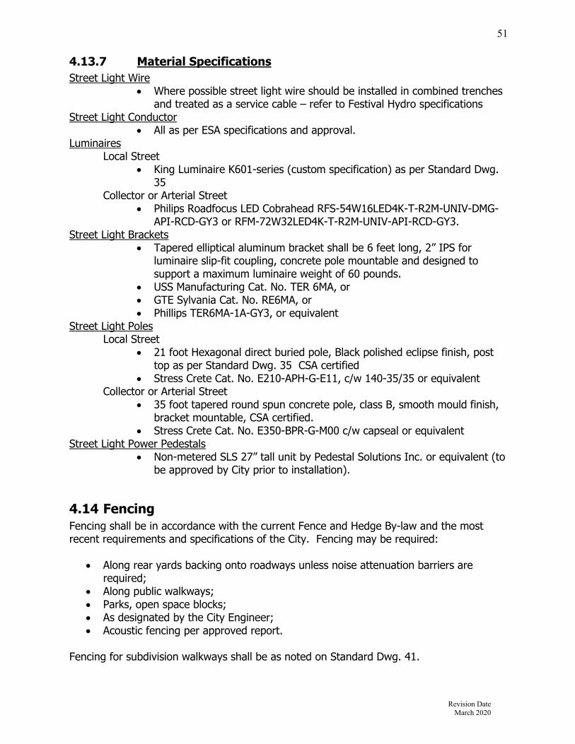
Revision Date March 2020
51
4.13.7 Material Specifications Street Light Wire
Where possible street light wire should be installed in combined trenches and treated as a service cable – refer to Festival Hydro specifications
Street Light Conductor All as per ESA specifications and approval.
Luminaires Local Street
King Luminaire K601-series (custom specification) as per Standard Dwg. 35
Collector or Arterial Street Philips Roadfocus LED Cobrahead RFS-54W16LED4K-T-R2M-UNIV-DMG-
API-RCD-GY3 or RFM-72W32LED4K-T-R2M-UNIV-API-RCD-GY3. Street Light Brackets
Tapered elliptical aluminum bracket shall be 6 feet long, 2” IPS for luminaire slip-fit coupling, concrete pole mountable and designed to support a maximum luminaire weight of 60 pounds.
USS Manufacturing Cat. No. TER 6MA, or GTE Sylvania Cat. No. RE6MA, or Phillips TER6MA-1A-GY3, or equivalent
Street Light Poles Local Street
21 foot Hexagonal direct buried pole, Black polished eclipse finish, post top as per Standard Dwg. 35 CSA certified
Stress Crete Cat. No. E210-APH-G-E11, c/w 140-35/35 or equivalent Collector or Arterial Street
35 foot tapered round spun concrete pole, class B, smooth mould finish, bracket mountable, CSA certified.
Stress Crete Cat. No. E350-BPR-G-M00 c/w capseal or equivalent Street Light Power Pedestals
Non-metered SLS 27” tall unit by Pedestal Solutions Inc. or equivalent (to be approved by City prior to installation).
4.14 Fencing Fencing shall be in accordance with the current Fence and Hedge By-law and the most recent requirements and specifications of the City. Fencing may be required:
Along rear yards backing onto roadways unless noise attenuation barriers are required;
Along public walkways; Parks, open space blocks; As designated by the City Engineer; Acoustic fencing per approved report.
Fencing for subdivision walkways shall be as noted on Standard Dwg. 41.

Revision Date March 2020
52
4.15 Easement Requirements
4.15.1 General Where underground services are placed outside road allowances and blocks of land under the ownership of the City, permanent easements are required. Generally, utility easements shall be centered over the common lot line between adjacent lots. Pipes shall be offset from the lot line by 0.6m. Where two pipes are located in one easement, the minimum width of the easement shall be the width required for the larger pipe plus ½ the width required for the small pipe. Refer to Dwg. 32.
4.15.2 Storm Sewer, Sanitary Sewer, and Watermain Easements The minimum width of easements for storm sewers, sanitary sewers, and watermains up to 450mm in diameter shall be 3.0m. For pipe sizes greater than 450mm or deeper than 2.0m, the developer shall provide calculations to determine the required width to allow sufficient room for trenching without disturbing any adjacent structures for the approval of the City. Refer to Dwg. 32.
4.15.3 Open Channels The minimum width of blocks of land for open channels shall be the width of the top of the channel plus 6.0 metres for maintenance requirements.
4.15.4 Overland Surface Flow The minimum widths of easements for overland surface flow shall be 4 metres.
4.16 Materials All materials must meet the requirements of the current OPSS and any additional specifications as noted below.
4.16.1 Concrete Mix for Sidewalk and Curb and Gutter All concrete shall be ready-mix concrete with the following minimum requirements:
Compressive Strength
30 mpa at 28 days
Air Entrainment 7% ± 1.5%Slump As per OPSS 1350Coarse Aggregate OPSS 1002 - November 2013 Table 5 is
modified to specify a maximum Petrographic Number (LS 609) of 125 for coarse aggregate for concrete for structures, sidewalks, curb and gutter, and concrete base.
The supply of concrete from other than a plant batch supplier will be accepted only upon written approval of the Engineer and must conform to OPSS Section 1350.04.01.02.

Revision Date March 2020
53
4.16.2 Superpave and Mix Design The Contractor will provide the City with the Superpave Mix Design Report for each superpave mix type to be used at least five business days prior to the commencement of the asphalt paving. The mix design shall be carried out in the same calendar year in which the asphalt paving work is performed. The mix proportions shall be corroborated by submission of a five point Marshall Mix Design, completed and reported in accordance with current MTO procedures, by a laboratory having Canadian Council of Independent Laboratories Type A Certification. A copy of the lab certification shall be submitted to the Engineering Division. Asphalt Cement The pavement Job Mix Formulae shall contain the following minimum percentages by weight of asphalt cement
Aggregate Aggregate requirements shall be as per the current OPSS 1003 Material Specifications for Aggregates - Hot Mix Asphalt. In addition to OPSS 1003 the Coarse Aggregate shall have a specified maximum Petrographic Number (LS609) of 125. Reclaimed Asphalt Pavement (RAP) and/or Roof Shingle Tabs (RST) are not permitted in any Superpave surface asphalt mix. RAP and/or RST are permitted in Superpave base mixes to a maximum of 15% by mass.
4.16.3 Granular ‘B’ Gradation Specifications for Type I Modified Granular B: MTO Sieve Designation % Passing by Mass 106mm 100 26.5mm 50-100 4.75mm 20-55 1.18mm 10-40 300um 5-22 75um 0-8
Mix Type Minimum %AC in JMF
Superpave 12.5mm FC1 4.8%Superpave 12.5mm 4.8%Superpave 19mm 4.6%

Revision Date March 2020
54
Section 5 – Sanitary Sewers 5.1 Sanitary Sewer System
5.1.1 General Sanitary sewers are required to carry domestic, commercial and/or industrial sewage from each area of the development under consideration. Flow is to be by gravity. Pumping sewage will be considered only where other alternatives are not possible and only with the approval of the City.
5.1.2 Non Permitted Flows The following items are not permitted to enter the sanitary sewer system:
Connections from foundation, weeping tile drainage or roof drainage, in accordance with City of Stratford Sewer Use By-law No. 65-70,
Any hazardous waste as defined under the EPA Regulation 558/00.
5.1.3 Abandonment of Existing Sewers When new sanitary systems are constructed to replace an existing sewer, all abandoned mains and maintenance holes must be removed in accordance with OPSS 510 and Standard Dwg 36. If removal is not possible or practical, due to access or other conditions, the abandoned mains and maintenance holes must be filled with an approved material, and the maintenance hole cover removed and sealed off, all as per the requirements of OPSS 510. The Engineering Division shall determine, in each case, if the existing infrastructure will be allowed to remain in place.
5.2 Hydraulic Design
5.2.1 Confirmation of Capacity Prior to commencement of any design for sanitary sewage works within the City, the applicant shall confirm with the City Engineer that adequate downstream sewer capacity is available for the proposed development. The sanitary sewer system shall be designed to service all areas within the development to their maximum future development in accordance with the City of Stratford Official Plan, the Northeast Secondary Plan, the West Secondary Plan and other documents as they become available. Allowance shall be made for inflows from the appropriate adjacent areas. The inflow rates utilized require the approval of the City. The proposed discharge into the existing sewer system, the type of connection, and the exact location the connection, requires the approval of the City. Refer to Section 2.5 for construction requirements for connecting to the City sewer system.

Revision Date March 2020
55
5.2.2 Sanitary Drainage Plan Sanitary drainage plans are to be drawn to a minimum scale of 1:1000 (a scale not exceeding 1:5000 will be accepted for large external areas) and are to indicate the total area to be serviced by the proposed sanitary sewers. Drainage/sub-drainage area limits for which sewers are to be designed for are to contain and follow the lot/block lines to the proposed maintenance holes located on the R. O. W. The sanitary drainage plan shall indicate but not be limited to the following:
Populations and areas (ha) of tributary area outside the development and for each section of the sanitary sewers within the development;
Street names; Maintenance hole numbers; Sewer sizes, slope and directions of flow; and Location of temporary plug(s) utilized to isolate new system from existing sewers.
5.2.3 Flow Calculations Sanitary sewer flows are to be submitted on standard sanitary sewer design sheets and be determined using the following design criteria:
5.2.3.1 Residential Average flow - 0.004 l/s/c. Average people per unit - 2.4 Use actual or projected populations based on information (zoning or otherwise) to
be provided by the Municipality. For calculation purposes, zoning densities are as follows:
Zone Density (units per ha)R1 20R2 30R3 40R4 50R5 100
FR-1 25 Peak the average flow using the Harmon Formula.
𝑀 1
14
4 √𝑃 𝑃 𝑃𝑜𝑝𝑢𝑙𝑎𝑡𝑖𝑜𝑛/1,000
5.2.3.2 Industrial Average flow: 0.50 l/s/ha Use higher design flows for point sources known to have significantly greater flows
than the average design allowance Use actual flows for large known discharges Use peaking factor of 2.0 or as per MECP guidelines “Typical Industry Sewage Flow
Peaking Factors” if approved by City

Revision Date March 2020
56
5.2.3.3 Commercial Average flow – City Core/Hotel =1.15 l/s/ha; Plaza/Highway = 0.3 l/s/ha Use higher design flows for point sources known to have significantly greater flows
than the average design allowance. Use actual flows for large known discharges Peak using a factor of 2.5
5.2.3.4 Schools As per MECP guidelines Average flow is 86.4 m3/ha/d or 1.0 l/s/ha. Peak using a factor of 2.5 resulting in a peak flow of 2.5 l/s/ha.
5.2.3.5 Other Miscellaneous Average Flow Rates Hospitals: 900 – 1800 l/bed/day Campgrounds: 225 – 570 l/campsite/day, 800 l/campsite/day with water supply Trailer parks: 340 l/space/day with no water supply Mobile home parks: 100 l/space/day with no water supply Motels: 150-200 l/bed/day Use appropriate peaking factors (MECP)
5.2.3.6 Infiltration Add an infiltration allowance of 0.1 l/s/ha for Greenfield development Infiltration allowances for all other development shall be obtained from the City
Engineer
5.3 Sanitary Sewer Design
5.3.1 Location All sanitary sewers shall be located in the right-of-way as shown on the standard road cross-section. Sanitary sewers on private property are regulated by the OBC. Where there are no specific regulations in the OBC, details from this manual will apply.
5.3.2 Pipe Capacity Manning’s formula shall be used in determining the capacity of all sanitary sewers. The capacity of the sewer shall be determined on the basis of the pipe flowing full. The value of the roughness coefficient ‘n’ used in the Manning’s Formula shall be 0.013.
5.3.3 Flow Velocity Minimum acceptable velocity = 0.8 m/s under peak theoretical flows. Maximum acceptable velocity = 3.0 m/s under peak theoretical flows. Note: For all sewers less than 30% full, a minimum cleansing velocity of 0.6 m/s must be achieved, using actual flows, not peak theoretical flows.

Revision Date March 2020
57
5.3.4 Minimum Size The minimum allowable size for a sanitary sewer shall be 200mm in diameter. On private property the sanitary sewer shall adhere to the OBC Part 7.
5.3.5 Minimum Grade The minimum grade for the first upstream leg shall not be less than 1.0%. For sewers other than the first leg, the flow velocity criteria shall be used.
5.3.6 Depth For residential, commercial and institutional areas, the obvert shall be a minimum of 2.4m below the final road grade and a minimum of 1.0m below basement floor elevations. For industrial areas, the minimum depth to the obvert shall be 2.15 m. For depths over 5.0m, a secondary collection system may be required and must be approved by the City. The secondary collection system may be installed directly over the deep trunk sewer.
5.3.7 Curved Sewers Curvilinear sewers may be considered for sanitary sewers 600mm diameter and larger.
5.3.8 Limits All sewers shall be terminated at the subdivision limits when external drainage areas are being considered in the design with suitable provision in the design of the terminal maintenance holes to allow for future extension of the sewer.
5.3.9 Pipe Crossings Generally, a minimum clearance of 0.25 m shall be provided between the outside of the pipe barrels at the point of crossing for storm and sanitary sewers. The minimum clearance provided between sanitary sewer and watermain crossings shall be as per MECP requirements. In the event the minimum clearance cannot be obtained, then the pipes shall be backfilled with unshrinkable fill as per OPSS 1359 and OPSS 350. In addition, if the minimum clearance cannot be obtained between a watermain and a sewer, the sewer should be designed and constructed equal to the water pipe and should be pressure tested at 350kPa (50psi) to assure water tightness.
5.3.10 Changes in Pipe Size No decrease of pipe size from a larger upstream to a smaller downstream will be allowed regardless of the increase in grade.

Revision Date March 2020
58
5.3.11 Pipe Bedding The class of pipe and the type of bedding shall be selected to suit loading and proposed construction conditions. Details of the types of bedding are illustrated in the Ontario Provincial Std. Dwg.s. Granular bedding shall be Granular ‘A’ and shall extend 300 mm minimum above the top of the pipe. The width of the trench at the top of the pipe must be carefully controlled to ensure that the maximum trench width is not exceeded unless additional bedding or higher pipe strength pipe is used.
5.4 Maintenance Holes
5.4.1 Location Maintenance holes (MHs) shall be located at each change in alignment, grade or pipe material, at all pipe junctions, at intervals along the pipe to permit entry for maintenance to the sewer, and at termination points of sewers. Wherever possible, MHs shall be located a minimum of 1.5m away from the face of curb and/or any other service. Refer to Section 2.5 for additional construction requirements for MHs connecting to the City sewer system.
5.4.2 Maximum Spacing The maximum spacing for maintenance holes shall be as follows for the sewer diameters indicated:
Up to 1350mm 120m Larger than 1350mm at approval of City
5.4.3 Maintenance Hole Types Maintenance holes (MHs) 3000mm and smaller shall be precast concrete. All sanitary MHs shall have monolithic base units and watertight pipe connections (Kor-N-Seal or approved equal). The Ontario Provincial Standard MH details shall be used for design where applicable. In all cases where the Std. Dwgs are not applicable, the MHs shall be individually designed and detailed. A reference shall be made on all profile drawings to indicate the type and size of all sanitary MHs. In the case of the standard 1200mm precast MH, the size may be omitted and reference need only be made to the Std. Dwg. number. Maintenance hole tees are not allowed for any sanitary sewer less than 1200mm diameter. For sanitary trunk sewers greater than 1200mm diameter, refer to section 6.5.4. Precast MHs shall conform to ASTM Specification C-478 latest revision.

Revision Date March 2020
59
5.4.4 Maintenance Hole Design All maintenance hole chamber openings shall be located on the side of the MH parallel to the flow for straight run MHs, or on the upstream side of the MH at all junctions. The MH shall be centred on the sanitary sewer main. Connections shall be as per OPSD 708.020. The maximum change in the direction of flow in any sanitary sewer MH shall be 90 degrees. In pipe sizes 675mm or greater, the maximum change in the direction of flow shall be 45 degrees. Drop structures shall be used when invert levels of inlet and outlet sewers differ by 0.9 metres or more as per OPSD 1003. The drop pipe shall be one size smaller than the inlet pipe. Minimum drop pipe size is 200mm. Wherever feasible, sewer systems should be designed to avoid the use of drop structures. Maintenance holes smaller than 1800mm dia require external drop structures. Internal drop structures are acceptable for MHs 1800mm dia or greater. All MHs shall be benched as per OPSD 701.021. Refer to Section 2.5 for additional requirements. Where hydraulics require benching to be different from OPSD 701.021, a benching detail is required. All MHs are required to have frost straps as per OPSD 701.100. Frost strapping may be modified with the approval of the City Engineer. Maintenance holes adjustment units shall be as per Section 6.10.2 All sanitary MHs require the installation of a waterproof membrane (Blueskin or equivalent) at all joints. Safety gratings shall be required in all MHs greater than 9.0 m in depth. Safety gratings shall not be more than 9.0 m apart and shall be constructed in accordance with the OPSD details. Where practical, a safety grating shall be located 0.5 m below the drop structure inlet pipe.
5.4.5 Minimum Invert Drop Where pipes enter and leave inline or at angles of 0 to 45, the minimum drop from invert to invert across the MH shall be 0.030m. Where pipes enter and leave at angles of 45 to 90, the minimum drop from invert to invert across the MH shall be 0.060m. Regardless of the minimum invert drop, the obvert of the outlet pipe shall not be higher than the obvert of the inlet pipe at any maintenance hole. Hydraulic calculations shall be submitted for all junction and transition maintenance holes on sewers where the outlet is 1050mm in diameter or greater. In addition, hydraulic calculations may be required for MHs where the outlet pipe is less than 1050mm in diameter if, in the opinion of the City Engineer, there is insufficient invert drop provided across any maintenance hole.

Revision Date March 2020
60
5.4.6 Maintenance Hole Lids/Covers All maintenance hole covers shall be as per OPSD 401.01 with Type A closed cover. All lids must be provided with support as per Std. Dwg. 18. Maintenance hole frames and covers are to be clear of curb and gutters on bends in the road for new construction. Maintenance hole frames and covers may be located in the curb and gutter on reconstruction projects, only as approved. Watertight Maintenance Lids/Covers Watertight MH lids are required when sanitary MHs are located within overland storm flow routes. These locations are within flood plain areas, within gutter locations and within an easement and/or open space area where overland flow is directly over and/or adjacent to the MH lids. Watertight lids are also required under sanitary surcharge conditions and when located in close proximity to sag areas on streets. Watertight MH lids shall be Ergo locking covers and frames with Cam Lock key handle or approved equivalent. Lockable Maintenance Hole Covers Lockable maintenance hole covers may be required to reduce access by the public. They can be located through park blocks, open space blocks, pumping stations or pollution control plants. See OPSD 401.06 for details and additional design information.
5.4.7 Grades for Maintenance Hole Frame and Covers All maintenance holes located within the travelled portion of the roadway shall have the rim elevation initially set flush with the base course asphalt. A maximum of 300mm of modular rings shall be permitted on all MHs in new subdivisions. Prior to the placement of the final course asphalt, the MH frame shall be adjusted to suit the final surface asphalt elevation. Steel adjusting rings will not be permitted.
5.5 Sanitary Service Connections All sanitary sewer service connections for single, semi-detached, and townhouse dwelling units shall be individual services. Connections shall be as per OPSD 1006. All new PVC sanitary service laterals shall be GREEN. All new sanitary service lateral locations shall be marked from the invert by a standard 2x4 piece of lumber, a minimum of 1metre above finished grade and painted brown. Infill lot developments must replace any existing sanitary service that does not have root proof gasketed connections, unless otherwise approved by the Engineering Division. Industrial and commercial services shall have an inspection maintenance hole installed at the property line.

Revision Date March 2020
61
5.5.1 Location Services shall be installed perpendicular to the main wherever practical in locations as shown on Std. Dwg. 11.
5.5.2 Connection to the Main The connection to the main sewer shall be made with an approved manufactured tee. Approved saddles or pre-manufactured tees, in accordance with OPSS 410 shall be used for connecting to existing sewer mains. Where a lot severance or lot infill condition exists, and a new sanitary service will be connected to an existing sanitary main, the developer or their agent must determine if the existing sanitary sewer is at risk of surcharging, or has a history of surcharging. This information can be obtained from the Engineering Division. If it is determined that there is a surcharge risk, the developer must provide surcharge protection to their development. No service connection of a size greater than half the diameter of the main shall be cut into the main sewer except for a 150mm service connection which will be permitted to connect to a 200mm and 250mm main sewer providing an approved manufactured tee is installed and providing the invert of the service connection is above the springline of the main sewer. A minimum clearance of 150mm under/over the storm sewer and watermain is to be provided, provided that minimum MECP requirements are achieved. For private drain connections that cross over or under a watermain larger than 450mm diameter, 500mm clearance is required. The Engineering Division must review and approve this crossing. All bends on sanitary service connection shall be long radius, sweep bends.
5.5.3 Connections to Maintenance Holes Sanitary service connections to MHs are permitted. If the invert of the service entering the MH is 900mm or more above the lowest invert, a drop pipe must be installed inside the MH to direct flow to the main channel in a manner to avoid splashing and the accumulation of debris on the benching. The MH shall be sized accordingly for internal drop (a minimum internal clearance of 1200mm is required).
5.5.4 Minimum Size and Grade The minimum service size and grade is 125mm PVC SDR28 @ 2.0%. Service sizes for development other than single residential units shall be in conformance with the OBC. The maximum service slope is 8%.
5.5.5 Depth For single family, semi-detached, and townhouse units, the obvert depth of the service connection at the property line shall be: Minimum 2.50 m Maximum 3.00 m Risers shall be used when the obvert depth of the sewer main exceeds 4.50 m. The riser section shall not exceed 3.0 m in depth. Vertical risers shall not be permitted.

Revision Date March 2020
62
5.5.6 Connection to Commercial / Industrial / Institutional and other Blocks
An inspection maintenance hole shall be required on the private property located 1.5 m from the property line to the centre of the rim.
5.6 Pipe Materials All sanitary sewers up to and including 375mm in diameter shall be PVC pipe. Pipe material for all sanitary sewers exceeding 375mm in diameter shall be constructed of polyvinyl chloride (PVC) pipe or reinforced concrete pipe subject to the approval of the City. On private property, materials for sanitary building sewers and private sewers shall comply with Part 7 of the OBC. Circular PVC pipe and fittings complete with bell and spigot joints, rubber gasket, lubricant and all other necessary appurtenances shall be manufactured in conformance with OPSS 1841 and shall be certified to CSA B182.2 for PVC Sewer Pipe and Fittings. PVC pipe shall have a minimum pipe stiffness of 320 kPa. Circular concrete pipe and fittings shall conform to OPSS 1820 and shall be manufactured at a plant certified under the Ontario Concrete Plant Prequalification Program. Non-reinforced concrete pipe shall be according to CSA A257.1. Reinforced concrete pipe shall be according to CSA A257.2. Joints and gaskets shall be according to CSA A257.3. Pipe materials for sanitary sewer mains, fittings and service laterals shall be CSA certified and shall conform to the following: Approved Sanitary Sewer Pipe Materials
Type of Pipe Specification Diameter Approved Use
Reinforced Concrete
CSA A257.2 375mm and larger
mainline
SDR 35 PVC CSA B182.2, 320 kPa Stiffness
200mm and larger
mainline
SDR 28 PVC CSA B182.2, 625 kPa Stiffness
125mm to 150mm
service laterals
Note: The City will not accept plastic pipe over 525mm diameter. Sanitary Forcemain Material Sanitary forcemain material shall be selected to suit the installation and system requirements and be pre-approved by the City. Under no circumstances shall the material selected for the forcemain be colour coded blue.
Revision Date March 2020
63
5.7 Testing
5.7.1 General All testing shall be carried out on each section of sewer including house service connection as work progresses in accordance with the applicable OPSS and ASTM. All newly constructed sanitary sewers and maintenance holes shall be watertight and free from leakage. An infiltration or exfiltration test shall be completed on all sewers. The City shall be the sole judge of which test is to be undertaken. The Developer shall give the City Engineer 48 hours notice prior to testing. All testing shall be done in the presence of the Consultant and/or the City Inspectors. Results for test conducted in the absence of the City or their qualified representative consultant will not be accepted. Testing shall only be conducted after final backfill is placed. Geotechnical reports or verified field observations by the City Engineer shall be used to determine anticipated elevations of the groundwater table. The City may request the installation of piezometers to determine the groundwater levels at the section of pipes being installed. The general sequence of sanitary sewers testing is to be approved by the City Engineer, which may consist but is not limited to the following:
1. Cleaning and flushing with high-pressure blasting; 2. Deflection or out of round testing (for Thermo-Plastic pipes only); 3. Water-tightness (leakage testing); 4. CCTV records to be completed after testing and at the start of maintenance; and 5. Additional CCTV recording at the discretion of the City Engineer or their qualified
representative at a time prior to maintenance, and at the time prior to assumption of the works.
5.7.2 Infiltration Test An infiltration test shall be carried out where the groundwater at the time of testing is 600mm or more above the crown of the pipe throughout the section of sewer being tested. The allowable infiltration shall not exceed an amount based on the following calculation:
0.075 L/mm of pipe diameter/100 metres of sewer/hour
5.7.3 Exfiltration Test The type of required exfiltration test shall be prescribed by the City Engineer. Water Exfiltration Test Application of the water exfiltration testing, equipment and other specifications shall be in accordance with OPSS 410, ASTM C969M and as noted herein. The exfiltration test shall be carried out where the groundwater table is lower than 600mm above the crown of the pipe, of the highest point of the highest service connection included in the test section. The allowable leakage for the test section shall not exceed the following:
0.075 L/mm of pipe diameter/100 metres of sewer/hour.

Revision Date March 2020
64
Low Pressure Air Exfiltration Test Application of the low pressure air exfiltration testing, equipment and other specifications shall be in accordance with OPSS 410, ASTM C924, ASTM F1417-11 and as noted herein. Testing shall be conducted between two sequential maintenance holes or to where a sewer terminates at a stubbed end. The section being tested shall be plugged at both ends before slowly filling the pipe until a constant pressure of 24 kPa can be maintained. For every 300mm the seasonal high groundwater level is higher than the invert of the pipe, a 3.0 kPa increase in air pressure shall be applied. The air pressure shall be stabilized for five (5) minutes before the required 20.5 kPa plus the additional pressure allotted for the season high water table is maintained. The time it takes for the pressure to drop 3.5 kPa shall not be less than the times identified in the able below: Table 1 - Low Pressure Air Exfiltration Test (OPSS 410)
Nominal Pipe Size
(mm)
Minimum Time
(min:sec)
Length for Minimum Time
(m)
Time For Longer Length*
(sec) 100 1:53 182 0.623 150 2:50 121 1.140 200 3:47 91 2.493 250 4:43 73 3.893 300 5:40 61 5.606 375 7:05 48 8.761 450 8:30 41 12.615 525 9:55 35 17.171 600 11:20 30 22.425 675 12:45 27 28.382 750 14:10 24 35.040 825 15:35 22 42.397 900 17:00 20 50.450
*If the length of the test section is greater than the length shown in Column C, the testing time shall be the product of the length of the test section multiplied by the value in Column D (i.e. Minimum time = test length x Column D).
5.7.4 Deflection Test A deflection test shall be performed on all sewers constructed using PVC material. All testing must be carried out in the presence of the City Inspector. The allowable deflected pipe diameter is calculated as: 7.5% of the Base Inside Diameter of the Pipe, or as per OPSS 410.07.16.05. Where the base inside diameter is defined in the CSA or ASTM standard to which the pipe is manufactured.
Revision Date March 2020
65
A suitable designed device as defined below shall be pulled through the pipe sewer to demonstrate that the pipe deflection does not exceed the allowable deflected pipe diameter. The device shall be pulled manually through the pipe not sooner than 30 days after the completion of backfilling and installation of service connections. The suitable designed device shall be a mandrel, cylindrical in shape, and constructed with an odd number of evenly spaced arms or prongs, minimum 9 in number. The minimum diameter of the circle scribed around the outside of the mandrel arms shall be equal to the allowable deflected pipe diameter ±1mm. The contact length of the mandrel shall be measured between the points of contact on the mandrel arm or between sets of prongs. This length shall not be less than that shown in OPS 410, Table 2. The mandrel shall be checked with a go-no-go proving ring. The proving ring shall have a diameter equal to the allowable deflected pipe diameter ±1mm. An accepted mandrel shall not pass through the proving ring. The proving ring shall be fabricated from steel minimum 6mm thick. Any section of pipe that does not allow the mandrel to pass shall be considered to have failed the deflection test. All sections of pipe that fail the deflection test shall be repaired and retested. Deflection testing shall be done not sooner than 30 days after the completion of backfilling and installation of service connections.
5.7.5 Video Record All newly constructed sanitary sewers shall be flushed and T.V inspected upon satisfactory completion of all other testing, both prior to the City’s issuance of Preliminary Acceptance, and prior to Final Assumption. All work done shall meet the requirements of OPSS 409. A permanent record in digital format video form (mpeg) shall be supplied, illustrating a continuous record of the sewer installations, service connection, maintenance holes, etc. A report identifying any unusual or substandard conditions shall be submitted. The file naming convention shall be :
“Street._starting mh-ending mh” Example: John St._MH1-MH2
The Consultant shall obtain maintenance hole identification numbers prior to the work being completed, and those numbers must form part of the video and report. The Consultant shall review the video record and provide written certification that the sewers so inspected are acceptable. The digital format video recording and the inspection report shall be prepared by a competent firm approved by the City. All video CDs, reports and data provided from these inspections shall become the property of the City. The inspection report shall include a plan with corresponding infrastructure identified. At the discretion of the City Engineer, additional inspections and records may be required prior to “Final Acceptance”.

Revision Date March 2020
66
Section 6 – Storm Drainage and Stormwater Management The Developer is required to produce an overall storm drainage and stormwater management plan that meets the objectives and requirements of the City, MECP, and the Upper Thames River Conservation Authority. The developer shall ensure that any development or redevelopment minimizes the impact of change to the groundwater regime, increased pollution, increased erosion or increased sediment transport, especially during construction.
6.1 Erosion and Sediment Control The City requires developers, contractors and builders to plan and execute their operations so as to minimize sediment and debris pickup and transport to sewers, roads, and water bodies. The degree of control and methods used must meet the regulations and guidelines of the City of Stratford, MECP, MNR, MTO and UTRCA. The City expects all erosion control works to be properly maintained throughout the duration of the project. All erosion and sediment control measures shall be inspected by the Consultant once per week during construction, once per month after construction is complete and until assumption, and after each rainfall of 10mm or greater. Inspection reports shall be forwarded to the City Engineer within 5 days of inspection. Erosion and Sediment Control (ESC) measures shall be implemented on all development applications, including site plans, plans of subdivision, and infill applications.
6.1.1 Topsoil Stockpiles Any topsoil or earth material stockpiles to remain after area grading is completed shall not be located on any City property or lands to be conveyed to the City. The ESC plans shall indicate the proposed location, side slopes and volume of material. The maximum height of any stockpile shall be 8.0m and the maximum slide slope shall be 2:1. The maximum height for a stockpile may be reduced depending on the proximity to existing residential dwellings. Stockpiles shall be located in a manner to maximize the separation distance to existing residences, municipal streets and environmental features. Temporary swales shall be utilized to direct runoff from stockpiles to appropriate sediment and erosion control measures. After area grading is complete, stockpiles shall be stabilized with hydroseed to the satisfaction of the City Engineer.
6.1.2 Silt Fence Silt fences shall be installed along the limits of area grading activity where surface water drains toward adjacent property, infrastructure or environmental features. A double row of silt fence shall be constructed where area grading is adjacent to a watercourse, wetland or other environmentally sensitive feature. The double row shall be separated by a minimum 5.0m vegetated strip. Silt fence shall be constructed in accordance with OPSD 219.130. Silt fencing shall be maintained and remain in place until final lot or block grading and restoration. The ESC plans shall indicate the location of the silt fencing.

Revision Date March 2020
67
6.1.3 Temporary Drainage Swales Temporary drainage swales shall be used during area grading or after completion to direct surface runoff to sediment control facilities or other drainage outlets. Swales shall be sized to convey the post development, peak flow from the 5-year storm event. Swales shall have a minimum gradient of 1.0% with 3:1 side slopes. Swales shall be maintained and remain in place until final grading and restoration. The location, gradient, direction of flow, and a typical cross-section of the drainage swale shall be provided on the ESC plans.
6.1.4 Straw Bale Filters Straw bale filters may be constructed around drain inlets/outlets for temporary short term control measures.
6.1.5 Rock Check Dams Rock check dams are to be constructed in conjunction with an approved geotextile barrier within open drainage systems and temporary drainage swales. The maximum spacing for check dams shall be 30 metres. Rock check dams shall be constructed in accordance with OPSD 219.210 and 219.211. Rock check dams shall be maintained and remain in place until final grading and restoration. The ESC plans shall show the location of rock check dams and refer to City standards.
6.1.6 Rip Rap Rip rap is to be constructed in conjunction with an approved geotextile barrier within inlet/outlet structures, over flow protections, channel banks and gabions. Rip rap is to be graded in sizes as per the MTO Highway Drainage Design Standards, and in accordance with OPSS 1004.05.05 (concrete rubble is not acceptable).
6.1.7 Catchbasin Sediment Control During construction, all roadway catchbasins shall be provided with a sediment bag insert and this shall be maintained and remain in place until assumption. Rear lot and ditch inlet catchbasins shall be provided with a filter cover, filter barrier sox, sediment bag insert or approved equivalent. These sediment control measures must be maintained and remain in place until the contributing lot or block areas have been re-vegetated. All catchbasins shall be cleaned as a minimum at least once before base course asphalt is applied and just prior to assumption of the subdivision. The ESC plans shall indicate the type of inlet sediment barrier proposed, maintenance requirements and recommendations for removal or replacement during or after a winter season.
6.1.8 Stone Pad Construction Entrance – Construction Access In order to reduce the tracking of mud onto paved streets, a pad of crushed stone shall be constructed at the site entrance and exit leading onto any existing road. The stone pad shall be a minimum of 450mm thick, 30m long and 5m wide. The first 15m from the entrance/exit shall be constructed with 50mm clear stone. The remaining 15m shall be constructed with 150mm riprap. This stone pad must be maintained and stone replaced if deemed necessary by the City Engineer. If required, the drawings shall specify a required truck haul route.

Revision Date March 2020
68
6.1.9 Temporary Connections to Storm Sewer After installation of municipal storm sewer system and road base, the lot or block areas are typically pre-graded to a lower elevation relative to the top of road. This situation may create areas of storm drainage ponding. To alleviate this situation, temporary connections to the storm sewer shall be provided to ensure all areas have a positive drainage outlet. These connections shall be sized to convey the 5-year storm event and the inlet structures shall be complete with sediment traps or facilities in accordance with the size of the contributing area. The inlet structure shall consist of an appropriately sized perforated riser pipe. The riser pipe shall be wrapped in filter cloth and surrounded with 50mm dia clear stone. The temporary connections shall be maintained until removal. The ESC plans shall indicate the location and details of each connection along with the requirement for removal.
6.1.10 Construction Dewatering Discharge from dewatering of excavations for construction of municipal services shall be safely directed to ESC measures. Temporary piping, swales or filter rings shall be constructed to ensure that erosion from pump hose discharge is minimized and to direct the discharge to ESC measures. Adequate erosion protection shall be provided at all concentrated discharge points and rock check dams shall be installed on all temporary swales. Sediment bags shall be used on the end of discharge hoses where the discharge from the dewatering area has a sediment load. Discharge from well point dewatering systems may be discharge directly to a storm sewer subject to approval of the City Engineer. Approval will require water quality laboratory testing and comparison to City sewer use by-laws.
6.1.11 ESC Phasing ESC measures shall be designed and implemented for the phases identified below. ESC measures for each phase shall be clearly identified on the ESC plans. A summary of the ESC measures for each phase shall be provided in chart form on the ESC plans. The chart shall include information on timing for installation, inspection/maintenance requirements and timing for removal of ESC measures. Phase 1 - Topsoil Stripping and Area Grading Phase 1 shall include all ESC measures that must be in place before and during topsoil stripping or area grading activity. These measures include silt fences, mud mats, temporary drainage swales, rock check dams and any temporary sediment control facilities. The developer’s consultant shall arrange an inspection with City staff once installation of Phase 1 measures is complete and prior to any grading or stripping activity. Any deficiencies noted during this inspection shall be repaired prior to starting grading or stripping. The developer’s consultant shall undertake weekly inspections of the Phase 1 ESC measures and after each rainfall event. The developer’s consultant shall provide weekly written inspection reports to the City inspector noting deficiencies and repairs to ESC measures. The developer shall arrange for regular maintenance of measures to remove accumulated sediment and undertake repairs to ensure proper function. Phase 2 - Municipal Servicing Construction Phase 2 shall include all ESC measures that will be undertaken after area grading is completed and during or after construction of municipal servicing. These measures include

Revision Date March 2020
69
restoration of graded areas and topsoil stockpiles, temporary connections to the storm sewer system, and sediment traps. Phase 2 measures shall also include the removal of identified Phase 1 measures and replacement with measures such as temporary drainage swales, rock check dams or others as required on the ESC plans. The developer’s consultant shall undertake weekly inspections of the Phase 2 ESC measures and after each rainfall event. The developer’s consultant shall provide weekly written inspection reports to the City inspector noting deficiencies and repairs to ESC measures. The developer shall arrange for regular maintenance of measures to remove accumulated sediment and undertake repairs to ensure proper function. Phase 3 - Building Construction Phase 3 shall include the maintenance and repair of all Phase 1 or Phase 2 ESC measures that will remain in place until building construction is complete. Phase 3 shall also identify the removal of any ESC measures necessary to allow building construction to proceed. The timing for any such removals shall be just prior to building construction. The developer’s consultant shall arrange an inspection with the City inspector of all remaining measures prior to building construction. Any deficiencies noted during this inspection shall be repaired prior to building construction. The developer’s consultant shall undertake weekly inspections of the remaining measures and after each rainfall event. The developer’s consultant shall provide weekly written inspection reports to the City inspector noting deficiencies and repairs to ESC measures. The developer shall arrange for regular maintenance of measures to remove accumulated sediment and undertake repairs to ensure proper function.
Sample ChartESC Measure Timing for
Installation Inspection/Maintenance
Requirements Timing for Removal
Phase 1 – Topsoil Stripping and Area Grading Silt fence Mud mat Drainage swales Check dams Sediment control
facility Topsoil stockpile Others as required
Prior to topsoil stripping
Consultant to arrange inspection with City staff after installation.
Consultant to undertake weekly inspections and after each significant rainfall event. Regular maintenance to remove sediment and repair ESC measures
Just prior to final grading, replacement with Phase 2 measures, or construction of municipal services
Phase 2 – Municipal Servicing Construction Restoration
hydroseeding Sediment traps Drainage swales Temporary connections
to storm sewers Others as required
After area grading and storm drainage system installation is complete
Consultant to undertake weekly inspections and after each significant rainfall event. Regular maintenance to remove sediment and repair ESC measures
Just prior to final grading or building construction

Revision Date March 2020
70
Phase 3 – Building Construction Maintenance and
repairs to all remaining ESC measures as per detailed inspection with City staff.
Removal of identified Phase 1 or 2 measures.
Prior to building construction, ESC measures to be repaired as per City deficiency list
Detailed inspection of all remaining ESC measures with City inspector. Consultant to undertake monthly inspections and arrange for any repairs.
Just prior to final topsoil and sodding of lot/block areas
6.2 Storm Sewer System
6.2.1 General Storm sewers designed and constructed in accordance with the most recent requirements and specifications of the City are required on every street within all proposed plans of subdivision. Storm sewers shall be of adequate size and depth to provide service for the development of lands within the upstream watershed and/or for the drainage of any areas designated by the City. Storm drainage shall be directed to an outlet considered adequate in the opinion of the City and applicable agencies. In no case will an outlet be allowed to a natural watercourse or existing drainage system not having sufficient capacity for the proposed discharge. The Developer will be required to ensure that the development does not cause interference with the riparian rights of properties upstream or downstream from the development. Channel works, bridges, culverts and all other drainage structures or works shall be designed and constructed in accordance with the most recent drawings and specifications of all applicable agencies having jurisdiction. They shall be approved by all applicable agencies having jurisdiction including the City, MECP, UTRCA, MTO, MNR, DFO, etc.
6.2.2 Abandonment of Existing Sewers When new storm systems are constructed to replace an existing sewer, all abandoned mains and maintenance holes must be removed as per OPSS 510 and Standard Dwg. 36. If removal is not possible or practical, due to access or other conditions, the abandoned mains and maintenance holes must be filled with an approved material, and the maintenance hole cover removed and sealed off, all as per the requirements of OPSS 510. The Engineering Division shall determine, on a case by case basis, if the existing infrastructure will be allowed to remain in place.

Revision Date March 2020
71
6.3 Hydraulic Design
6.3.1 Storm Drainage Plans External Areas A plan shall be prepared to a scale dependent on the size of the watershed area, to show the nature of the drainage of the lands surrounding the development site and be compatible with the City’s latest contour mapping. The area to be developed and all existing contours used to justify the design shall be clearly shown. This plan shall be prepared and submitted to the City Engineer with the preliminary drawings (Section 2.2.1). Internal Drainage Plan Internal storm drainage plans are to be drawn to a minimum scale of 1:1000 and shall include all streets, blocks, lots and easements. The proposed storm sewer system shall be shown on this plan with all maintenance holes numbered consecutively from the outlet. The maintenance holes shall be the tributary points in the design and the area contributing to each maintenance hole shall be clearly outlined on the plan. The storm drainage plan is to be compatible with the proposed grading plan. The storm drainage plan shall indicate but not be limited to the following:
Existing contours, drainage patterns and adjacent lands; Runoff coefficients and areas (ha) of tributary area outside the development and for
each section of the storm sewers within the developments; Lot fabric; Direction of runoff; Street names; Maintenance hole numbers; Sewer sizes, slope and directions of flow; Any catchbasins or swales, on the lots or blocks, required to collect the runoff; Temporary or permanent quantity and quality stormwater management facilities; Major and minor overland flow routes; Culverts and other drainage appurtenances.
6.3.2 Rational Method Design calculations for storm sewer systems shall be completed on the Storm Sewer Design Sheets. The quantity of storm flow shall be calculated using the rational method as follows: Q=kAIC, where: Q = flow (m3/s)
k = 0.00277 A = contribution area (ha) I = rainfall intensity (mm/hr) C = runoff coefficient
For design purposes drainage areas shall be allocated to up-stream maintenance hole and not the downstream maintenance hole.

Revision Date March 2020
72
6.3.3 Design Storms Sewers in New Development, Infill and Redevelopment Areas - Storm sewers shall be designed to a 5-year storm event for full flow conditions. A higher return period may be adopted to lower the design HGL and to reduce site fill requirements as shown on Std. Dwg.s 13 and 14. Reconstruction of Existing Sewers - Unless otherwise requested by the City Engineer, storm sewers shall be designed using the 5-year return period. The developer shall confirm the appropriate design criteria with the Engineering Division. Sewers on Private Property - The City recommends storm sewer systems on private property be designed to a minimum 2-year storm. Culverts and Bridges - For channel, road culvert, bridge and/or erosion control projects the proponent is responsible for obtaining all necessary approvals from the governing agencies, including UTRCA, MNR, DFO, and/or MECP.
Road Classification Design Flood Frequency Arterial 1:100 Year to Regional Collector 1:50 Year Local 1:25 Year Temporary Detour 1:10 Year Driveway 1:5 Year
Open Channels - The proposed criteria for an open channel design shall be submitted to the City for approval prior to the actual design being undertaken. Major system overland flow channel designs may be required to accommodate the 250 year storm for new development. “Natural” channel design criteria will be determined on a site by site basis. The Consultant shall be responsible for obtaining any approvals that may be required from the MNR, MECP or the UTRCA.
6.3.4 Rainfall Intensity Values of rainfall intensity (I) shall be determined by: I = A / (t + B)C, where t is the time of concentration, and A,B, & C are defined in the following table:
Return Period A B C Duration
(hrs) 2 year 601.09 4.922 0.767 4 5 year 875.105 7.641 0.762 4
10 year 1062.156 9.025 0.760 4 25 year 1319.273 10.500 0.762 4 50 year 1560.739 12.129 0.767 4
100 year 1821.990 13.507 0.773 4 250 year 2095.179 13.509 0.773 24

Revision Date March 2020
73
6.3.5 Time of Concentration Minimums The minimum time of concentration shall be 15 minutes for most residential and open space, and 10 minutes for industrial, commercial, institutional and apartments. External Lands
To calculate the initial time of concentration for upstream, undeveloped lands, the following formulas may be used: Bramsby Williams, HYMO/OTTHYMO, SCS Upland Method, etc. The most appropriate method will be determined at the discretion of the City.
To calculate the initial external time of concentration for external lands that are scheduled for future development, a straight line is to be drawn from the furthest point within the watershed to the proposed inlet. The top 50 metres shall have an initial “t” of 10 minutes and the remainder shall have a “t” assuming the velocity in the sewer is 2m/s. The summation of the two “t”s will give the future external time of concentration.
Adjustment of Time of Concentration The time of concentration is to be adjusted when lateral flows account for 50% or more in the design flows. Adjusted time of concentration shall be calculated using the formula:
𝑇 𝑇 𝑄 𝑇 𝑄
𝑄 𝑄
where :
Tc-adj = adjusted time of concentration (min.)Tct = time of concentration in the trunk sewer (min.) Qt = design flow in the trunk sewer (l/s)Tcl = time of concentration in the lateral sewer (min.) Ql = design flow in the lateral sewer (l/s)
The adjusted time of concentration is used downstream of the junction maintenance hole.
6.3.6 Runoff Coefficient Values of runoff coefficient (C) shall be as per the following table:
Land Use Runoff Coefficient
COMMERCIAL Composite INDUSTRIAL Composite RESIDENTIAL - Single Family
- Row Dwellings / Townhouses - Apartments
0.55 0.75
Composite SCHOOLS, CHURCHS, HOSPITALS CompositePARKS / OPEN SPACE 0.25EXISTING DEVELOPED AREAS Composite

Revision Date March 2020
74
Composite runoff coefficients area generated assuming C=0.2 for pervious and C=0.9 for impervious areas. The table below may be used for guidance.
% impervious Runoff Coefficient0 0.210 0.2720 0.3430 0.4140 0.4850 0.5560 0.6270 0.6980 0.7690 0.83100 0.9
For reconstruction of existing sewers, runoff coefficients for existing large drainage areas may be obtained from the City Engineering Division.
6.4 Storm Sewer Design
6.4.1 Location The storm sewer shall be located in the right-of-way as shown on the City of Stratford standard roadway cross-sections. All storm sewers shall be laid in a straight line between maintenance holes unless radial pipe has been designed. The minimum separation distance between sewers shall be 2.5m as per MECP requirements. Special cases may be reviewed for site specific design constraints and depths. Storm sewers on private property are regulated by the Ontario Building Code (OBC). Where there are no specific regulations in the OBC, details from this manual will apply.
6.4.2 Pipe Capacity Manning’s Formula shall be used in determining the capacity of all storm sewers. The capacity of the sewer shall be determined on the basis of the pipe flowing full. The value of "n" using Mannings formula shall be:
Concrete, PVC, HDPE 0.013 Concrete Box Culverts 0.013 Corrugated Steel Pipe (CSP) 0.024
6.4.3 Flow Velocities The minimum velocity allowed for storm sewer is 0.60 m/sec and the maximum allowable is 6.0 m/sec under peak theoretical flows. In the last reach before the outlet, the maximum allowable velocity shall be 4.0m/s. Energy dissipation controls shall be provided as required.

Revision Date March 2020
75
6.4.4 Minimum Sizes Sewer
Main Catchbasin Connection
DCB Connection
Entrance Culvert
Road-Crossing Culvert
Min. Pipe Diameter 300mm 250mm 300mm 450mm 600mm Private sewers shall be sized in accordance with the Ontario Building Code.
6.4.5 Minimum Grades The minimum gradient for the first reach of permanent dead end sewer shall be 1% where feasible. For sewers other than the first permanent dead end reach, the flow velocity criteria shall be used to limit pipe gradient.
6.4.6 Depth The storm sewers, including catchbasin connections, shall have a minimum of 1.5 metres frost cover. Where the minimum cover is not possible, the Consultant shall provide a design solution with consideration for additional loading due to frost.
6.4.7 Curvilinear Sewers Curvilinear sewers may be considered for storm sewers 600mm diameter and larger only upon written approval of the City Engineer and provided that a maintenance hole is located at the beginning or at the end of the radial section.
6.4.8 Elliptical Sewers Elliptical pipe may be utilized for clearance and/or cover purposes.
6.4.9 Limits All sewers shall be terminated at the subdivision limits when external drainage areas are considered in the design with suitable provision in the design of the terminal maintenance holes to allow for the future extension of the sewer.
6.4.10 Pipe Crossings Generally, a minimum clearance of 0.25 m shall be provided between the outside of the pipe barrels at the point of crossing for storm and sanitary sewers. A minimum clearance of 0.5 m shall be provided between sewer and watermain crossings. In the event the minimum clearance cannot be obtained, then the pipes shall be backfilled with unshrinkable fill as per OPSS 1359 and OPSS 350. In addition, if the minimum clearance cannot be obtained between a watermain and a sewer, the sewer should be designed and constructed equal to the water pipe and should be pressure tested at 350kPa (50psi) to assure water tightness. In cases where the storm sewer crosses a recent utility trench at an elevation higher than the elevation of the utility, a support system shall be designed to prevent settlements of the storm sewer, or alternatively the utility trench is to be excavated and backfilled with compacted crushed stone or concrete to adequately support the storm sewer. When the storm sewer passes under an existing utility, adequate support shall be constructed to prevent damage to that utility.

Revision Date March 2020
76
6.4.11 Blind Connections Blind connections using factory made tees are permitted for:
Services less than 200mm Services less than one third (33%) of the diameter of the main line sewer. Catchbasin leads within road allowances
These requirements do not apply to rear yard catchbasins. A maintenance hole shall be installed for rear yard catchbasin connections.
6.4.12 Changes in Pipe Size No decrease of pipe size from a larger upstream to a smaller size downstream will be allowed regardless of the increase in grade, with the exception of stormwater management facilities as approved by the City Engineer.
6.4.13 Safety / Rodent Grates Manufactured safety / rodent grates are required on open inlets and outlets 300mm and larger, except in driveway culverts.
6.4.14 Pipe Bedding The class of pipe and the type of bedding shall be selected to suit loading and proposed construction conditions. Details of the types of bedding are illustrated in the Ontario Provincial Std. Dwg.s. Granular bedding shall be Granular ‘A’ and shall extend 300 mm minimum above the top of the pipe. The width of the trench at the top of the pipe must be carefully controlled to ensure that the maximum trench width is not exceeded unless additional bedding or higher pipe strength pipe is used.
6.5 Maintenance Holes
6.5.1 Location Maintenance holes (MHs) shall be located at all junctions, changes in grade, material, size, or alignment (except with curvilinear sewers), and termination points of sewers. Wherever possible, MHs shall be located a minimum of 1.5m away from the face of curb and/or any other service.
6.5.2 Maximum Spacing The maximum spacing for MHs shall be as follows for the sewer diameters indicated:
Up to 1350mm inclusive 120m Larger than 1350mm at approval of City

Revision Date March 2020
77
6.5.3 Maintenance Hole Types Maintenance holes (MHs) 3000mm in diameter and smaller shall be precast concrete. The standard MH details as shown on the OPS Drawings shall be used for MHs. In cases where the Std. Dwgs are not applicable, the MHs shall be individually designed and detailed. A reference shall be made on all profile drawings to the type and size of all storm maintenance holes. Precast MHs shall conform to ASTM Specifications C-478 M latest revision. At new MHs, support for pipes shall be as per OPSD 708.020. At existing MHs that are rough opened, concrete bricks and mortar shall be used to fill voids. Clay bricks, stones and rubble shall not be used. The inside wall of the opening shall have a smooth mortar finish. If the existing structure is cored, a flexible maintenance hole adapter shall be installed.
6.5.4 Tee Maintenance Holes Tee maintenance holes are permitted provided that:
No change in slope No change in direction 1200mm or larger pipe
6.5.5 Maintenance Hole Design The maximum change in the direction of flow in any storm sewer MH shall be 90 degrees. In pipe sizes 675mm or greater, the maximum change in the direction of flow shall be 45 degrees. Connections shall be as per OPSD 708.020. When the difference in elevation between the obvert of the inlet and outlet pipes exceeds 0.9 m, a drop structure shall be placed on the inlet pipe as per OPSD 1003. The drop pipe shall be one size smaller than the inlet pipe. Minimum drop pipe size is 200mm. Maintenance holes smaller than 1800mm dia require external drop structures. Internal drop structures are acceptable for MHs 1800mm dia or greater. All MHs require benching at the bottom of the MH and shall conform to OPSD 701.021. Where benching is different from OPSD 701.021, a benching detail is required. All MHs shall be benched up ¾ of the pipe height regardless of the pipe size. All MHs are required to have frost straps as per OPSD 701.100. Frost strapping may be modified with the approval of the City Engineer. Catchbasin maintenance holes shall be provided with a 600mm deep sump. The MH shall be adequately sized to receive pipes as per OPSD 701.021. The minimum MH size is 1200mm diameter. Safety gratings shall be required in all MHs greater than 9.0 m in depth. Safety gratings shall not be more than 9.0 m apart and shall be constructed in accordance with the OPSD details. Where practical, a safety grating shall be located 0.5 m below the drop structure inlet pipe.

Revision Date March 2020
78
6.5.6 Minimum Invert Drop Where pipes enter and leave at angles of 0 to 45, the minimum drop from invert to invert across the MH shall be 0.030m. Where pipes enter and leave at angles of 45 to 90, the minimum drop from invert to invert across the MH shall be 0.060m. Regardless of the minimum invert drop, the obvert of the outlet pipe shall not be higher than the obvert of the inlet pipe at any MH location. Hydraulic calculations to provide suitable drops to compensate for the loss in energy due to the change in flow velocity and for the difference in the depth of flow in the sewers shall be submitted for junction and transition maintenance holes on sewers where the outlet is 1050mm diameter or greater.
6.5.7 Frame and Cover All MH covers shall be as per OPSD 401.010 with Type B open cover. All lids must be provided with support as per Std. Dwg. 18. Lockable maintenance hole covers may be required to reduce access by the public. They can be located through park blocks, open space blocks, pumping stations or pollution control plants. See OPSD 401.060 for details and additional design information.
6.5.8 Grades for Maintenance Hole Frames and Covers All MHs located within the travelled portion of a roadway shall have the rim elevation set flush to the base course of asphalt. Prior to the placement of the surface course asphalt the MH frame shall be adjusted to the finished grade of asphalt. Steel adjusting rings will not be permitted. The setting of the frame and cover shall be in accordance with the details on the OPS Drawings. A maximum of 300mm of modular rings shall be permitted on MHs in new subdivisions.
6.6 Catchbasins
6.6.1 Location and Spacing Catchbasins shall be located at the standard gutter location. Offset curb and gutter is not permitted. Double catchbasins are required at all low points, when water is collected from two directions. A single catchbasin may be considered if the total aggregate spacing to the adjacent catchbasins is less than the maximum spacing allowable, as noted below. The maximum spacing for catchbasins including cul-de-sac gutters and distance from high point shall be:
For two (2) lane roads 90m For four (4) lane roads 60m For all roads with grades equal to or greater than 5% 60m
The Designer shall ensure that the catchbasin spacing is adequate to collect the storm water.

Revision Date March 2020
79
Roadways - Catchbasin locations should not conflict with future driveways. Intersections - Catchbasins shall be generally located upstream of sidewalk crossings at intersections. On street corners and intersections, the catchbasin is to be located on the upstream side where the road grade falls towards the intersection, 0.6 m from the BC or EC of the curb curvature, and/or located to avoid conflicts with driveway and lot servicing. Lots / Rear Yard - The catchbasin and lead are to be located 0.6 m from the property line. Parks - Catchbasins are to be located to minimize flow across pathways and provide positive drainage from park facilities.
6.6.2 Catchbasin Types Catchbasins shall be of the precast concrete type as shown on the OPS Drawing 705.010 (single) or OPSD 705.020 (double). Special catchbasins and inlet structures shall be fully designed and detailed by the Consultant. In situations where inlet control catchbasins are required, detailed calculations of the flow and the hydraulic grade line may be required.
6.6.3 Catchbasin Connections
Type Minimum Size Of Connection
Minimum Grade Of Connection
Single Catchbasin 250mm 1.0% Double Catchbasin 300mm 1.0% Rear Lot Catchbasin 300mm 1.0%
Catchbasin leads shall be connected as follows:
Catchbasins within 9.0m of a MH are to have their leads connected into the MH. Catchbasin leads 9.0m to 15.0m may have their leads connected into the main
sewer. Catchbasin leads 15.0m to 30.0m in length may be constructed either by having a
catchbasin at one end and the other connected into a MH or a sewer 900mm in diameter and larger, or by having the lead connected into a sewer 825mm in diameter or smaller at one end with a MH catchbasin at the other end.
Catchbasin leads over 30.0m in length are to be connected into a MH or a sewer 900mm in diameter or larger at one end and have a MH catchbasin at the other end.
6.6.4 Frame and Grate The frame and cover for catchbasins in roadway or walkway areas shall be as per OPSD 400.020. Catchbasins located within the traveled portion of the roadway shall have the frame elevation set flush with the surface of the base course asphalt. The frame shall be adjusted immediately prior to placement of top course asphalt. Curb at these locations can be formed from asphalt during this temporary period. The adjustment and setting of the frame and cover shall be completed in accordance with the details provided in OPSD 704.010 and OPSD 704.011.

Revision Date March 2020
80
All lids must be provided with support as per Std. Dwg. 18. Catchbasins in grassed areas shall have a Birdcage Grate as per OPSD 400.120.
6.6.5 Sumps All catchbasins are to have 600mm sumps.
6.6.6 Rear Yard Drainage A maintenance hole is required at the connection of a rear yard catchbasin to the main line regardless of the lead size.
6.7 Storm Service Connections All new PVC storm service laterals shall be WHITE. All new storm service lateral locations shall be marked from the invert by a standard 2x4 piece of lumber, a minimum of 1metre above finished grade and painted green.
6.7.1 New Development Residential private drain connections shall be as per Standard Dwg. #12. Individual drain connections are required for each dwelling unit of semi-detached and town home buildings. Other arrangements are possible in exceptional circumstances (i.e. high ground water table) and are to be approved by the City Engineer. (See Standard Dwg. #13) The developer shall confirm with Festival Hydro if storm service connections are required for proposed transformer vaults.
6.7.2 Infill or Redevelopment Private drain connections shall be reviewed based on the criteria contained in Standard Dwg #14. When connecting PDC’s to existing sewers in a lot infill situation, connections must be made utilizing an approved saddle or premanufactured tee, in accordance with OPSS 410. A minimum clearance of 150mm under/over the sanitary sewer and watermain is to be provided. For PDCs that cross over or under a watermain larger than 450mm diameter, 500mm clearance is required. The Engineering Division must review and approve this crossing.
6.7.3 Location Services shall be installed perpendicular to the main wherever practical. Service connections for single family and semi-detached dwellings shall be installed in locations as shown on the City of Stratford Std. Dwg.s. Where design constraints arise (i.e. top end of cul-de-sac or crescent) PDCs may have to be located in reverse location and identified as such on the servicing drawings. Sewer connections for single and semi-detached dwellings shall be made with factory made fittings.

Revision Date March 2020
81
Storm PDCs 300mm in diameter and larger are to be connected to the main sewer at a maintenance hole, except in cases where the main sewer is 900mm in diameter or larger, in which case the PDC may be connected directly into the sewer.
6.7.4 Minimum Slope and Diameter The minimum grade and service size is 100mm PVC SDR28 @ 2.0%. Service sizes for development other than single residential units shall adhere to the OBC. The maximum service slope is 8%
6.7.5 Depth The storm service obvert at property line shall be a minimum of 1.2m below the finished grade.
6.7.6 Flow Direction Changes Horizontal bends are to be avoided.
6.7.7 Rainwater Leaders For new development, rainwater leaders for single and semi-detached dwellings shall not be connected directly to the sewer systems. Leaders must discharge to concrete splash pads in landscaped areas and directed to side yard swales. All other buildings shall discharge rainwater leaders to grade where possible. For infill or redevelopment, rainwater leaders for all buildings shall discharge to grade where proper drainage can be achieved and no adverse impact to neighbouring properties will occur.
6.8 Channels and Culverts The proponent is responsible for obtaining all necessary approvals from the governing agencies, including UTRCA, MNR, DFO, and/or MECP for channel, culvert, bridge and/or erosion control projects.
6.8.1 Culverts and Bridges Headwalls are not permitted on driveway culverts. All culverts must be of sufficient length to provide for a minimum 3:1 slope off the driving surface to the ditch invert. Bridges and other major drainage structures shall require special designs as determined by the City of Stratford. Hydraulic calculations will be required. The frequency and magnitude of flooding or erosion shall not be increased on upstream or downstream properties.

Revision Date March 2020
82
6.8.2 Open Channels “Natural” channel design criteria will be determined on a site by site basis. The following guidelines must be considered: Open Channels Minimum Velocity Maximum Velocity Grass lined – Natural 0.7 m/s 1.5 m/s Grass lined – Maintained 0.7 m/s 1.5 m/s Gabion lined 0.7 m/s 2.5 m/s Concrete lined 0.7 m/s 4.0 m/s
6.8.3 Watercourse Erosion and Bank Stability Where erosion or bank instability is already evident in an area to be developed or re-developed, the City requires that the situation be stabilized by appropriate remedial measures. Where development will cause significantly increased downstream erosion, the City also requires the Developer to mitigate further damage by appropriate remedial measures. Where designing remedial erosion or bank stabilization works, preservation of the watercourse dynamics and natural valley aesthetics must be secondary only to achieving a sound technical solution. A normal bank flow channel has a capacity of about the 1:2 year flood. Protection to this level will be adequate provided care is taken to prevent any damage by higher floods and provided that the channel bank is not coincident with a higher valley bank. In this latter case, it may be necessary to protect the bank to a level as high as the 1:100 year flood or even the flood resulting from the Regional storm. The proposed criteria for an erosion or bank stability design shall be submitted to the City and the UTRCA for approval prior to the actual design being undertaken.
6.9 Inlets and Outlets
6.9.1 General Inlet and outlet structures shall be fully detailed on the engineering drawings. The details provided shall include the existing topography, proposed grading and the works necessary to protect against erosion. The inlets and outlets must be protected to prevent unauthorized access and debris accumulation.
6.9.2 Inlets Adequate means such as gabion baskets, rip-rap or concrete shall be provided at all inlets to protect against erosion and to channel the flow to the inlet structure and at all outlets to prevent erosion. The extent of the erosion protection shall be indicated on the engineering drawings and shall be dependent upon the velocity of the flow in the storm sewer outlet, the soil conditions, the flow in the existing watercourse and site conditions.

Revision Date March 2020
83
Inlet grates shall generally consist of inclined parallel bars or rods set in a plane at approximately 18 degrees with the top away from the flow. Precaution must be taken in the design of grating for structures to minimize the risk of entanglement or entrapment of a person.
6.9.3 Outlets For outlets 450mm diameter or smaller, OPSD 800.010 may be used where appropriate. Head walls must be used for all 525mm diameter and larger sewers, permanent pool or submerged conditions. The OPSD 804.030 standard headwall shall be used for storm sewers up to 600mm in diameter. For sewers over 600mm in diameter, the headwall shall be as per OPSD 804.040 or individually designed. The concrete for all headwalls is to have a minimum strength of 30 MPa with a 5% to 7% air entrainment and 70mm to 90mm slump. Weeping tiles are to be provided on each side at the base of the sewer outlet and extended through the headwall. On larger headwalls they are placed on the side or wing walls. Baffle posts are to be provided for sewer flows between 2.1 m/s and 4.6 m/s. The location of the posts shall be as per the type of headwall (refer to Municipal Works Design Manual). The height of the baffle posts should be equal to the full depth of flow. All headwalls shall be equipped with a hot dipped galvanized grating over the outlet as per OPSD 804.050. The grating is to be placed over the storm outlets horizontally or vertically as required and should be fixed to the headwall with anchor bolts. A handrail as per OPSD 980.101 shall be installed around headwalls 1.2m or more in height or which exceed 1.0m in height from the top of the headwall to the proposed top of slope. All headwalls are to have a swale at the top of the structure to allow for surface drainage. Outfall structures to existing channels or watercourses shall be designed to minimize potential erosion or damage in the vicinity of the outfall from maximum design flows. The obvert of the outlet pipe is to be above the 25 year flood elevation of the receiving channel. Rip rap is to be constructed at the end of all headwalls of all storm sewer systems and is to be placed in accordance with OPSD 810.010 and the following design criteria:
(i) On the bottom and sides up to design water levels; (ii) Downstream until the projection of the side walls meet the channel side
slopes at half the design water depth of flow; and (iii) For headwalls at creeks and rivers, extend rip rap or gabion protection to
creek or river.

Revision Date March 2020
84
6.10 Materials
6.10.1 Pipe Materials Both rigid and flexible pipe are permitted in the construction of storm sewer systems including private drain connections and catchbasin leads. These materials include concrete and PVC. On private property, materials for storm building sewers and private sewers shall comply with Part 7 of the OBC. Circular concrete pipe and fittings shall conform to OPSS 1820 and shall be manufactured at a plant certified under the Ontario Concrete Plant Prequalification Program. Non-reinforced concrete pipe shall be according to CSA A257.1. Reinforced concrete pipe shall be according to CSA A257.2. Joints and gaskets shall be according to CSA A257.3. Circular PVC pipe and fittings complete with bell and spigot joints, rubber gasket, lubricant and all other necessary appurtenances shall be manufactured in conformance with OPSS 1841 and shall be certified to either CSA B182.2 for PVC Sewer Pipe and Fittings or CSA B182.4 for Profile PVC Sewer Pipe and Fittings. PVC pipe shall have a minimum pipe stiffness of 320 kPa. Pipe materials for storm sewer mainline, fittings and service laterals shall be CSA certified and shall conform to the following:
Approved Storm Sewer Pipe Materials
Type of Pipe
Specification Diameter Approved Use
Concrete CSA A257.1 Extra Strength
250mm to 300mm
catchbasin lead and service connections
200mm to 300mm
service connections
Concrete CSA A257.2 Reinforced
300mm and larger
mainline and service connections
SDR 35 PVC CSA B182.2 –320 kPa Stiffness
200mm and larger
Mainline, catchbasin lead and service connections
SDR 28 PVC CSA B182.2 –625 kPa Stiffness
100mm to 150mm
service connections
Note: The City will not accept plastic pipe over 525mm diameter.

Revision Date March 2020
85
6.10.2 Maintenance Hole and Catchbasin Adjustment Units Concrete adjustment units shall be as per OPSS 407. Precast adjustment units shall be laid in a full bed of mortar with successive units being joined using sealant as recommended by the manufacturer. A minimum of one adjustment unit shall be installed with a minimum height of 75mm. A maximum of four adjustment units may be installed to a maximum height of 300mm. Concrete brick and mortar shall not be used. Rubber adjustment units as per OPSS 1853 or HDPE as manufactured by IPEX under the trade name “Lifesaver” are also acceptable.
6.11 Testing
6.11.1 Deflection Test A deflection test shall be performed on all sewers constructed using PVC material. Refer to Section 5.7.4.
6.11.2 Video Record All newly constructed storm sewers shall be flushed and T.V inspected upon satisfactory completion of all other testing, both prior to the City’s issuance of Preliminary Acceptance, and prior to Final Assumption. All work done shall meet the requirements of OPSS 409. A permanent record in digital format video form (mpeg) shall be supplied, illustrating a continuous record of the sewer installations, service connection, maintenance holes, etc. A report identifying any unusual or substandard conditions shall be submitted. The file naming convention shall be :
“Street._starting mh-ending mh” Example: John St._MH1-MH2
The Consultant shall obtain maintenance hole identification numbers prior to the work being completed, and those numbers must form part of the video and report. The Consultant shall review the video record and provide written certification that the sewers so inspected are acceptable. The digital format video recording and the inspection report shall be prepared by a competent firm approved by the City. All video CDs, reports and data provided from these inspections shall become the property of the City. The inspection report shall include a plan with corresponding infrastructure identified. At the discretion of the City Engineer, additional inspections and records may be required prior to “Final Acceptance”.

Revision Date March 2020
86
6.12 Stormwater Management
6.12.1 General Requirements
6.12.1.1 Subdivisions and Condominium Developments All stormwater quality and quantity facilities shall be designed in accordance with the MECP Stormwater Management Planning and Design Manual and comply with the recommendations contained within the following:
City-Wide Storm System Master Plan South Side Storm System Class EA South Side Storm System Class EA Addendum Court Drain Sub-watershed Study NE Secondary Plan West Secondary Plan Various other studies and plans as they become available
The consultant shall ensure that all relevant planning, engineering and regulatory, requirements for each development have been obtained from or reviewed by the City before initiating design of any system.
6.12.1.2 Site Plans Infill and Re-development properties
For those developments whose total site area is less than 0.20ha, the developer must reduce post-development flows to the pre-development level for all design storms.
For all other developments, the developer must meet the requirements for infill developments as stated in the City Wide Storm Master Plan. At the City’s discretion, consideration to reduce the requirements may be given to those sites that do not propose expansion of hard surface areas.
It is the developer’s responsibility to contact the City to determine the appropriate level of stormwater management control for each site.
Rational method calculations are allowed for site plans with a total lot area less than or equal to 0.4ha. When using the rational method for calculations, runoff coefficients shall be increased 10% for the 25year storm, 20% for the 50year storm, and 25% for the 100year and above storm events (to a maximum of C = 1.0) as per MTO Drainage Management Manual Design Chart 1.07. Greenfield developments
The developer must meet the requirements as stated in section 6.12.1.1 Quality Control All developments must provide Stormwater quality control to achieve MECP Enhanced level of protection, which achieves a minimum of 80% of the long-term sediment removal. The Consultant shall review and recommend lot level controls, conveyance controls and end-of-pipe stormwater controls to provide quality treatment of stormwater. For developments where there is a potential for spill contamination, an appropriate end-of-pipe treatment such as an oil grit separator will be considered mandatory.

Revision Date March 2020
87
Major Overland Flow Routes All existing major overland flow routes, as identified in the City Wide Storm System Master Plan, must be accommodated across the property to be developed. It is the developer’s responsibility to contact the City to obtain the required design information in each case. Stormwater Management Report Where conventional wetpond facilities are not feasible or recommended, the submission requirements as detailed below should be modified to reflect the end-of-pipe quality treatment proposed and any on-site quantity storage utilized (ie dry pond, parking lot, roof top etc).
6.12.2 Stormwater Management Report Developments will require a SWM report or design brief to be read in conjunction with the design drawings. Hydrologic studies must describe the model parameters and criteria for their selection as well as input and output data. The Consultant has the responsibility for the computations, and the Engineering Division shall check the main assumptions and the input data. All information required for this verification shall be submitted with the report. Reports are to be bound with a pocket at the rear for insertion of plans. The following information is required to be incorporated into all stormwater management reports: Name of the project, and date of the report to be shown on the front cover. A summation of the selected criteria along with references to governing documents
and background reports researched. Geotechnical report should contain the following information: borehole/test pit logs
(minimum of three boreholes or test pits, minimum depth 5.0m); water table elevation, soil types, hydrologic soil group along with percolation rate of predominant soil type (mm/hr), curve number (CN) and how determined, surface characteristics, percolation rate in mm/hr.
Manning’s ‘n’ for impervious areas should be in the range of 0.013 – 0.015. Gravel and crushed asphalt to be considered as pavement for post-development modeling purposes.
Breakdown of land-use composition in terms of runoff coefficients. Pond stage-storage-discharge table. Existing and proposed catchment area plan which delineates internal/external
drainage areas and labels areas and catchment reference numbers. Table of “Pre” and “Post” development catchment parameters. Table of “Pre” and “Post” development peak flows for all storms. Hard and digital copies of all modeling for quality and quantity control. All
calculations to be completed in Metric (SI Units). Orifice and weir formula/calculations. Draw down time/calculations. Additional dead storage to be provided within water quality ponds. Stormwater management plan(s) – see 6.12.4. Monitoring, maintenance and operation requirements – see 6.12.5. Report to be signed and stamped with a Professional Engineer’s seal.

Revision Date March 2020
88
6.12.3 Software The following software may be used for hydrologic modeling: MIDUSS, Interhymo, Otthymo, PC-SWMM, and Visual Otthymo. Other models or methods of calculation must be approved by the City Engineer prior to submission. Models used for site analysis for subdivisions should coincide with the models used in the Watershed or Sub-Watershed plan (where applicable).
6.12.4 Stormwater Management Plan This plan will be used to validate the drainage patterns and parameters to be used in the post-development stormwater management modeling. The following information is required to be shown on this plan:
Drawing to be done in metric units to a measurable scale Geodetic benchmark, and local bench mark Legend, North Arrow Municipal Address and Legal Property Description Professional Engineer’s Seal (signed and dated) Site Location Plan Property lines and all applicable bearings and distances of each property line Street names Post-development drainage boundaries and corresponding areas All proposed site surface features such as buildings, sheds, walkways, driveways,
fences, surface materials (i.e. concrete, gravel, asphalt), patios Permanent, extended detention, highest water levels on plan view and include all
ponding levels for various return periods in tabular form Section/details of major overland flow routes Section/details of maintenance access routes Section/details of erosion protection at inlet/outlet structures and on spillways Borehole location and existing groundwater level Sediment forebay details including lining and separation berm Details of sediment drying area where implemented Section/details of inlet/outlet structures Sanitary maintenance holes located within the ponding limits are to be fitted with a
water tight lid (OPSD 401.050) Standard Notes Each SWM Plan shall bear a note making reference to all other plans included with the SWM Report. Reference should also be made to the stormwater management report itself, the date of the report, and the Landscaping Plan, if applicable (e.g. This plan to be read in conjunction with the Servicing Plan, Landscape Plan, etc, and the Stormwater Management Report dated _____).

Revision Date March 2020
89
6.12.5 Facility Monitoring, Maintenance and Operation Detailed monitoring, maintenance and operation requirements must be included in the Stormwater Management Report for both stormwater management facilities (ponds etc) and stand- alone water quality units (oil/grit separators etc).
Identify long and short term facility maintenance and operation requirements, including, but not limited to: - Estimates of frequency of sediment removal; - Labour, equipment and material costs; - Alternative methods of removal based on the facility design; - Estimates of associated annual and capital costs; - Method of stabilization of all disturbed areas; and - Immediate repair or replacement of all worn, missing, and damaged structures.
Document maintenance and operations requirements as a separate report section. Identify facility monitoring requirements including:
- Monitoring equipment and specifications; - Quality/quantity parameters to be monitored; - Duration of monitoring; - Location and installation of field equipment; - Frequency of sampling or field measurements; - Laboratory testing or analysis requirements; - Baseline monitoring requirements; - Reporting frequency and methodology; and - Estimates of annual monitoring and reporting costs.
6.12.6 Stormwater Management Components These design criteria are considered supplemental to the latest revision of the MOE (MECP) Stormwater Management Practices Planning and Design Manual. Quality and Quantity Control Facilities Facilities shall be designed to minimize any adverse effects to the environment as well as ensuring the safety of local residents. Wet ponds that exceed 3.0 metres in depth shall have terraced slopes to facilitate maintenance of the facility. The minimum slope of the bottom of the pond shall not be less than 1.0 percent. Under no circumstances should the contours of the land in such detention ponds be altered after construction without notifying the City Engineer and the UTRCA. It must be agreed by all concerned that such modification will have no detrimental effect on stormwater management. The City may require fencing, signage, shrubbery and/or vegetation in association with stormwater management facilities. Inlet and Outlet Structures The inlet and outlet structures must be designed as much for ease of operation as for hydraulic efficiency. The designer should always consider the possibility of a plugged outlet and should design a maintenance feature for drainage. The inlets and outlets must be
Revision Date March 2020
90
protected to prevent child and major debris access. The area at the downstream end must be protected against erosion by channel lining and/or energy dissipater. Inlet and outlet structures shall be fully detailed on the engineering drawings. The details provided shall include the existing topography, proposed grading and the works necessary to protect against erosion. Storm sewer inlets into the facility are to be designed so that the invert matches the permanent pool water level. Erosion protection shall be provided between the headwall and the bottom of the forebay to prevent localized scour at the inlet. The protection shall match the width of the headwall at the inlet and shall extend 1.5m on either side of the headwall at the forebay bottom. Protection material shall consist of rip-rap or river stone underlain with geotextile with size and depth of stone based on consultant recommendations. Maintenance access roadways shall extend to the top of slope/berm above inlet structures. A geodetic monument shall be established on the top of the concrete headwall to City standards. Reverse pipe outlet structures are preferred for both wetland and wet pond facilities. Where site grading permits, maintenance pipes shall be installed to allow the facility to drain by gravity flow. Maintenance access roadways must extend to provide access to maintenance access covers on outlet structures. A weir outfall/spillway will be considered for discharge of less frequent events. Erosion protection for outfalls shall generally consist of a combination of rip rap or river stone and vegetation as per Standard Dwg #27. The size and depth of stone shall be based on consultant recommendations based on flow velocity calculations. Additional information is available within the MTO Highway Drainage Design Standards. Maintenance Access Roadway Maintenance accesses are required from municipal road allowances to outlet/inlet structures and to the bottom of sediment forebays. Dead end access roads are not preferred, and shall be designed with a proper hammerhead turn around with a minimum hammerhead width of 17.0m and a 12.0m centreline turning radius. The access roadway shall have a minimum of 4.0 metre width, maximum 3% crossfall, maximum 10% gradient and minimum 12.0m centreline radius. Blocks between residential lots for the purpose of maintenance access shall have a minimum width of 6.0m with a 4.0m wide road surface. A suitable curb cut shall be provided at the street connection and removable bollards shall be installed at the edge of the R.O.W. to prohibit public vehicular access. Concrete sidewalk across the access road shall be a minimum 200mm thick with wire mesh reinforcing. Road base is to consist of a minimum 300mm of Granular B supported by appropriate geotechnical recommendations with a surface treatment of turfstone or approved equivalent. Where the access road will also be used as part of a walkway or trail system, it must be AODA compliant and the surface treatment shall be 50mm of HL3 asphalt. Access roads on blocks between residential lots shall have a 200mm concrete surface from curb to rear of lot.

Revision Date March 2020
91
Forebay The forebay bottom (not including side slopes) shall be lined with 300mm of 50mm diameter crusher run limestone (or as recommended by a geotechnical consultant) to support the use of equipment to remove the sediments from the forebay. A geotechnical engineer shall certify that the forebay lining will provide adequate support for maintenance equipment. The use of maintenance equipment presumes that the forebay is dewatered prior to sediment removal. A dewatering sump shall be installed in each forebay to facilitate dewatering in accordance with Standard Dwg. # 28. Sediment Drying Area A sediment drying area shall be provided immediately adjacent to the maintenance access road and located as close as possible to the sediment forebay. The drying area shall have a surface area equivalent to the area of the bottom of the forebay. This area shall be graded at a 2.0 to 5.0% slope with surface drainage directed to the facility. Surface treatment shall be consistent with the maintenance access roadway. Emergency Overflow Spillway Each facility shall be designed to provide an emergency overflow spillway to allow safe storm drainage to exit safely in the event of a failure at the outlet or a storm event greater than the 250yr design storm. The spillway shall be designed to convey the 250yr peak flow, while maintaining a 0.10m freeboard to the top of the slope around the perimeter of the facility. The invert of the spillway shall be above the 250yr water level in the facility. Erosion protection shall be provided on the top, downslope and base of the spillway. Because of aesthetics and the infrequent use of the spillway, erosion protection shall consist of a soil re-inforcement system with a natural vegetated surface treatment. The type of system shall be based on consultant recommendations based on flow velocity calculations. Major System Overland Flow Routes The major overland flow routes shall not be directed into the sediment forebay area. Channels designed to convey overland flows shall be flat bottomed with 3:1 maximum side slopes. The maximum flow depth shall be 0.45m and the channel depth shall allow for 0.1m of freeboard. Because of aesthetics and the infrequent occurrence of major system flows, erosion protection shall consist of a soil re-inforcement system with a natural vegetated surface treatment. The type of system shall be based on consultant recommendations based on flow velocity calculations. Orifice Installations For parking lot or similar detention areas, the minimum size of orifice to be used as an outlet control is 50mm. Typical catchbasin or maintenance hole orifice installation details are shown on Standard Dwg. 16. These drawings are schematic and subject to detailed design by the engineer. Municipal facilities shall have removable orifice plates as per Standard Dwg. #29, or be comprised of an approved manufactured Inlet Control Device. All orifice plates shall be manufactured from non-corrosive metallic material.

Revision Date March 2020
92
Oil/Grit Separators All fuelling areas and loading docks where sediments and petroleum may collect are to be fitted with an approved oil/grit separator, potentially in addition to an oil/water separator. “Maintenance hole” type OGS units are recommended. Concrete separators used in areas subject to hazardous materials (i.e. petroleum, etc.) should be provided with an impermeable/resistant liner to guard against contamination of the concrete unit.

Revision Date March 2020
93
Section 7 – Watermain
7.1 General Developments must be serviced from the existing municipal water distribution system. The Developer shall provide and construct, at their own cost, a watermain suitable for supplying the entire project, interconnected where possible, and the connection to the nearest 150mm diameter or larger watermain including any necessary easements, to the satisfaction of the City. Abutting private owners may connect to this connecting watermain without charge by the Developer. In order to provide a proper and reliable water distribution system within the development, reasonable looping of the system shall be provided to the satisfaction of the CITY. Should the Developer/Owner propose to phase the servicing of the development, the CITY reserves the right to comment and/or alter the proposal, in order to service the development in a safe and logical order. The following information relates to the specifications for the installation of watermains and service connections to be installed and connected to the City water distribution system. This information applies to installation of PVC and ductile iron pipe up to 300mm in diameter and to water service pipes up to 50mm in diameter. All AWWA standards used shall be to the most current edition.
7.2 Location and Design The Ministry of the Environment Design Guidelines for Drinking Water Systems 2008, or latest addition, provides the minimum requirements that must be met. In addition, the following criteria must be included in the Design presented for approval.
7.2.1 Mains Mains shall be located as shown on the City’s typical cross-sectional drawings. It is recognized that this standard applies where straight runs are being installed. On curves, the main location may deviate slightly from the standard by using the maximum allowable deflection in the pipe joints. The number of special bends should be kept to a minimum. The cover of the mains should be a minimum of 1.8m to a maximum of 2.0m. Deviations from this cover may be made upon approval in writing from the City Engineer. The watermain diameter shall be approved by the City Engineer. The diameter of a permanent dead-end watermain shall not exceed the diameter of the source watermains. No main less than 150mm in diameter shall be installed.
7.2.1.1 Vertical Connection to Existing System In the event that the existing watermain has less than 1.8m of cover, vertical bends shall be utilized as necessary at the construction limits to connect the new watermain (at proper depth) to the existing system. This method of connection facilitates the future lowering of the remainder of the existing watermain. Sweeping vertical pipe joint deflections shall not be used.

Revision Date March 2020
94
7.2.1.2 High Points High points shall be avoided unless an escape route for trapped air is provided. For local watermains, services will generally provide an escape route for trapped air but it is preferred to locate fire hydrants at high points. Air release valves shall not be installed on local watermains without the approval of the City Engineer.
7.2.1.3 Dead-end Mains Dead-end watermains are to be avoided wherever possible. Where dead-end watermains cannot be avoided, the maximum length of a permanent dead-end watermain is 100metres unless approved in writing by the City Engineer. A fire hydrant must be located at the end of cul-de-sacs and other permanent dead-ends. A temporary fire hydrant must be installed in-line at temporary dead-ends. An acceptable alternative is to provide a plug on the main line leg of the hydrant tee and install a fire hydrant in its permanent location. Should there be no suitable location for a hydrant, a 50mm blow-off will be provided in accordance with Std. Dwg. W3. The blow-off must be designed in such a manner as to convey the water to a suitable drain, which must be operable without the need for excavating.
7.2.1.4 Thrust Restraint Mechanical joint restraints and/or concrete thrust blocks shall be installed to restrain movement of the watermain. The limits for which mechanical joints restraints must be installed shall be clearly indicated on the Construction Drawings. The restraining joint and pipe design shall be based on transferring thrust through the pipe to the surrounding material. Refer to AWWA C600 (Ductile Iron) and C605 (PVC). In areas where there is little “undisturbed” soil, particularly reconstruction projects or congested works, mechanical joint restraints shall be installed and specified on the Construction Drawings. Thrust restraint shall be provided at all fittings, bends, tees, valves, hydrants, crosses, reducers and plugged or capped dead ends. All rods and bolts on mechanical restraints must be wrapped with Petrolatum tape or equivalent to prevent corrosion. Please refer to Corrosion Protection in section 7.6. Valves All inline valves up to 300 mm in size shall be mechanically restrained. In addition, one
full pipe length (6m) on each side of the valve shall be restrained. Bends All bends up to 200 mm in size must be mechanically restrained two full pipe lengths.
There must be a minimum of two steel rods on all restraints. All bends from 250 mm to 300 mm in size shall be mechanically restrained. In addition,
two full pipe lengths (12m) on each side of the bend shall be restrained. There must be a minimum of four steel rods on all restraints.

Revision Date March 2020
95
Dead Ends All dead ended watermains up to 200 mm in size shall be mechanically restrained. The
cap and three full pipe lengths (18m) prior to the end of the watermain must be restrained with a minimum of two steel rods on the restraints.
All dead ended watermains 250 and 300mm in size cap shall be mechanically restrained. The cap and five full pipe lengths (30m) prior to the end of the watermain must be restrained with a minimum of four steel rods on the restraints.
Fittings All fittings including tees, reducers and crosses up to 300 mm in size shall be restrained. In addition, two full pipe lengths (12m) on each side of the fitting and must be mechanically restrained. There must be a minimum of two steel rods on all restraints 200 mm or less. There must be 4 steel rods on all restraints 200mm or greater. For Watermains larger than 300mm or installation situations not included in the above section, the restrained lengths shall be shown on the construction drawings as recommended by the pipe manufacture and approved by the City Engineer. For PVC Watermains, RCT™ Flex Tite fittings may be used without restraints but mechanical restraints will be required on additional pipe lengths listed above in this section. The City Engineer reserves the right to specify the use of mechanical restraints and/or concrete thrust blocks. Please see Drawing W8 and OPSD 1103.010B, OPSD1103.020
7.2.2 Valves Valves will normally be located by all intersections and must satisfy the following location criteria:
A maximum of 60 services will be isolated by operating no more than four valves At least 2 valves at tee intersections At least 3 valves at cross intersections Valves shall separate hydrants such that no two adjacent hydrants will be out of
service at one time. Valve locations shall be on the extension of the street line or at locations approved by the City Engineer where the extension of the street line intersects with curbs or other facilities that would make the street line extension location an awkward location. Hydrants shall be valved and the valving shall be in accordance with Drawing W2. Maximum Spacing In addition to the valving requirements outlined above, the maximum spacing for isolation valves shall be as listed for the following watermain diameters:
300mm and smaller 300m Larger than 300mm as directed by the City Engineer
Valve Chambers Valve chambers shall not be installed. All valves to be direct bury. Minimum Clearance The minimum clearance from above ground obstructions to valves is 2.0m.

Revision Date March 2020
96
7.2.2.1 Combination Air & Vacuum Release Valves Utilization Air and Vacuum Release Valves shall be utilized in watermains in situations where it is possible for air to accumulate or a vacuum to develop and an alternate means is not available (i.e. services or fire hydrants) to remove the air. The valves shall be located in accordance with best design practices. This generally includes supply watermains with localized high points, long stretches of flat or gently sloping watermain or at changes in grade. In general terms, Air and Vacuum Release Valves shall be of the combination configuration as per AWWA Standard C512. The sole use of either an air release or vacuum release valve must be dictated by the situation and approved by the City Engineer. Watermains servicing adjacent lots generally do not require air and vacuum release valves because air can escape through the services. A blowoff or fire hydrant is an acceptable alternate means of air or vacuum release in temporary situations with the approval of the City Engineer. Watermain Profile The Consultant, through a cost-benefit analysis, shall consider reducing the number of air and vacuum release valves by altering the profile of the watermain. Sizing Air Release and Vacuum Release valve bodies shall be 25mm for watermains up to and including 300mm diameter and 50mm for watermains larger than 300mm diameter. If the Consultant determines that a larger valve body is required, the size must be approved by the City Engineer. The orifice sizing shall be determined in conjunction with a transient analysis of the watermain and consultation with the manufacturer.
7.2.3 Blow-offs When dead end mains are encountered, it will normally be sufficient to provide a fire hydrant near this dead end for the purpose of blowing-off the main. Should this not be a suitable location for a hydrant, a blow-off will be provided in accordance with Drawing W3. The blow-off must be designed in such a manner as to convey the water to a suitable drain, must be operable without the need for excavating and will be a 50mm blow-off for all mains.
7.2.4 Water Service The minimum nominal service size shall be 25mm. The allowable service sizes are 25mm, 38mm, 50mm, 100mm, 150mm etc in 50mm increments. Services must be sized in accordance with the Ontario Building Code. The City Engineer must approve services sized larger than 300mm or alternate service sizing. The service size shall not exceed the diameter of the watermain. The service pipe is to be laid at right angles to the main and will normally extend in a straight line to the building. Each service must be independently valved. Its location will

Revision Date March 2020
97
normally be in accordance with the City’s standard location. Deviations from the above may be approved by the City Engineer, but all drawings must show the location of the service as installed. Any relocation work required because of violations of this requirement shall be at the expense of the Developer. If the location of future servicing is in doubt, then the servicing can only be installed with the written approval of the City Engineer. All buildings shall have their own water service as required by the Ontario Building Code. Where a fire service is required for a building, its installation must conform to the Ontario Building Code. In this situation, the domestic service must be tapped outside with separate shut off, and a backflow preventer must be provided inside the building on the fire service. Fire services are not metered.
7.2.5 Backflow Prevention Where, in the opinion of the City Engineer, a backflow prevention device is required, said device will be installed by the Developer at their expense. These devices will be in accordance with the AWWA standards. Prior to any work involving the City water system and supplying water for testing, flushing and chlorination, a double check valve backflow device is required as per AWWA standard C510. The backflow device must isolate the non-potable water system or service from the City water system at all times. The backflow device must be supplied by the Contractor with certification from an accredited tester, indicating that it has been tested prior to use and/or re-tested if taken out of service and placed in another location within the City. City of Stratford Bylaw 50-2004 lists accredited testers. The backflow device must only be used for potable water sources.
7.2.6 Service Valves Where the service is 50mm in diameter or less, a corporation stop shall be installed at the main and a curb stop at the property line. For services larger than 50mm in diameter, a single valve will be installed at the property line, if the main can be closed down during its installation. If the main cannot be closed down, a tapping sleeve and valve will be installed at the main. If the shut off valve is connected to non-metallic watermain, tracer wire must be connected using approved direct bury connectors. In building complexes such as town housing developments or shopping plazas, where individual services are connected to a larger common service, a valve shall be placed on each individual service where it joins the common service. The valve must be easily accessible for operation and must be in accordance with drawings approved by the City Engineer. Sectionalizing valves on the common service may also be required as deemed necessary by the City Engineer. All services 50mm and under shall have two isolation valves. One valve shall be installed immediately adjacent to the watermain (main stop) and buried, and another valve shall be installed at the property line or easement limit (curb stop) and a service box provided to finished grade. For more detail refer to the Appendix A - City of Stratford Service Regulations.

Revision Date March 2020
98
7.2.7 Meters A meter will be required on all services. A ball valve shall be installed on street side of meter. The meter shall be installed immediately inside the wall of the building. Variations must be approved by the City Engineer. Sufficient space for installation and maintenance must be provided with the meter protected against freezing and accessible for meter reading. Water softeners must be at least 1 m from water meter for maintenance purposes. Where the meter is 25mm or larger, a by-pass for this meter must be installed. For smaller than 25mm meters, by-passes will be installed where the customer cannot tolerate a shut-down of the water service during normal working hours. Such locations include coin-operated equipment at a Laundromat, services where there is water-cooled equipment, production line where a shut-down of approximately one hour would create problems. Meters will generally be one size smaller than the size of the service. The size of the meter must be negotiated with the City Engineer in accordance with the flow requirements. The Developer is referred to the minimum bill requirements of the City, which relates to meter sizes. Fire services do not require metering.
7.2.8 Hydrants Hydrants will be located as agreed upon by the City Engineer. Generally, hydrant spacing will not be approved in excess of 122m or a maximum of 90m from the face of a house. Where necessary and required by the Fire Department or as arranged by property owners, hydrants will be located on private property. The preferred locations for the fire hydrants are:
At street intersections; On the same side of the road as the watermain; At the end of cul-de-sacs and other permanent dead end watermains; Consistently on the same side of the road as existing and future fire hydrants; At the dividing property line between adjacent properties; At high points; and At low points.
If the adjacent property is developed (i.e. re-construction projects), new fire hydrants must be placed within 45m of existing siamese or similar fire connections on buildings in accordance with the latest edition of the Ontario Building Code. Fire hydrant leads must be installed perpendicular to the road and/or the watermain. Hydrants must have a minimum 1.5m clearance (separation) from any curbing, sidewalks, driveways, or utility appurtenances (to allow for future maintenance, snow plowing etc.). All hydrants in new developments shall be subject to flow testing in accordance with City requirements. Testing shall be completed after commissioning of the watermain and results shall be submitted to the City Engineer for acceptance.

Revision Date March 2020
99
7.2.9 Chlorine Residual Maintenance A distribution system that includes dead-end watermains shall be designed to mitigate the degradation of chlorine residuals. The DEVELOPER shall provide a Chlorine Residual Maintenance Plan that includes:
Flushing plan during development, that accommodates any phasing contemplated; Form of flushing : blow-offs, automatic flushers, or manual flushing. The City shall
approve the method of flushing; Location of flushing – indicate the locations of all temporary dead-ends and permanent
dead-ends. The Plan shall confirm the locations may be adequately flushed; Determination of frequency of flushing – the Plan shall state the volume of water and
frequency of flushing that each dead-end watermain is to receive to ensure minimum chlorine residuals are maintained (0.05 mg/L Free Chlorine).
All water used shall be recorded by the CITY and charged to the DEVELOPER. All labour, materials, and equipment associated with flushing and confirmation of residuals shall also be the responsibility of the DEVELOPER. Upon assumption of the subdivision, all responsibility for determining and maintaining flushing requirements and associated costs shall be that of the CITY.
7.3 Installation of Watermains
7.3.1 Ductile Iron Please refer to ANSI/AWWA standards C600 for Installation of Ductile Iron Water Mains and their Appurtenances.
7.3.2 Polyvinyl Chloride (PVC) Please refer to ANSI/AWWA standard C605 for Underground Installation of PVC Pressure Pipe and Fittings for Water.
7.3.3 Line and Grade Developers shall provide stakes to indicate the line and grade in accordance with the approved drawing before beginning any work. No pipe shall be laid without at least three (3) sight rails in place. Mains shall be laid and maintained to the required grades and locations with all valves, fittings, hydrants, etc. to be plumb and in accordance with the drawing locations. No deviation in excess of 150mm will be permitted. The Contractor shall carry out explorations where necessary to establish or discover the location of existing pipes, conduits or other buried objects. Change in Line and Grade PVC Pipe may be deflected in order to follow the curvature of the trench. To achieve curvature, the pipe shall be installed in accordance with the manufacturer’s specifications. Directional change may be accomplished by axial flexure (pipe bending) or joint deflection of the pipe to the extent recommended by the manufacturer. However, under no circumstances will radii less than those specified in the tables below be permitted. Combination of the two methods is not permissible. In addition, the CITY reserves the

Revision Date March 2020
100
right to require the installation of additional bends to ensure that the pipe is not over-stressed by excessive joint deflection. Axial Flexure: Pipe Size (mm) Min. Radii of Curvature (m)
100 30 150 44 200 58 250 70 300 84
Joint Deflection: Pipe Size (mm) Min. Radii of Curvature (m) 100 116 150 116 200 116 250 116 300 140 350+ 233 Where it is not possible by using allowable joint deflection or pipe bending to lay pipe to the required radius or relocate pipe past an obstruction, bends must be used. Construction machinery shall not be used to bend PVC pipe.
7.3.4 Frozen Ground Do not place work on frozen ground. Should the bottom of the trench become frozen, remove and replace the frozen material with bedding material compacted to 95 percent Standard Proctor Density. Clear stone may be required.
7.3.5 Preparation of Trench All trenches shall be made in accordance with requirements of the Ontario Health and Safety Act O.Reg 213 Construction Projects. Trenches shall be provided so that pipe can be laid with the proper alignment and depth so as to provide a uniform and continuous bearing and support for the pipe on solid and undisturbed ground at all points between the Bell holes. Grade and shape the pipe trench and the specified bedding to give uniform and even bearing for the length of the pipe. Dig Bell holes at each joint. Make corrections in the grade with compacted granular material acceptable to the City Engineer. Where the subgrade in its natural state is inadequate to support the pipe, the Owner’s Geotechnical Consultant shall provide recommendations for the proper procedures. Remove the subgrade where it has been adversely changed by construction operations and is not adequate to support the pipe. Replace with crushed stone or other approved material as directed by the City Engineer. Trench in existing roadways in a manner to prevent overbreak. Saw cut pavement in clean, straight lines prior to the start of excavation.
7.3.6 Dewatering Always maintain the excavation free of water. Do not use sanitary sewers for the discharge of water from the trenches.

Revision Date March 2020
101
7.3.7 Backfilling Ductile Iron Backfill trenches from the top of the pipe bedding to the underside of surface restoration with site selected excavated material. Provide backfill free of roots, organic material and stone larger than 35mm. Place backfill material in lifts not exceeding 150mm. Compact to 95 percent Standard Proctor Density. Place backfill to 600mm above top of pipe by hand. If the City Engineer decides that the site selected excavation material, either wholly or partially, is not suitable for backfill, then provide imported material of a type approved by the City Engineer. Compact to 95 percent Standard Proctor Density. Backfilling on a public road allowance or in area that is to be designated as public road allowance shall be done in accordance with the requirements of the City Engineer – refer to Section 2.5. Sand and gravel backfill will be used if, in the opinion of the City Engineer, it is required. Excavated material may be used for backfill provided that such material is suitable for backfilling in the opinion of the City Engineer. All backfilling materials shall be free from foreign materials such as refuse, cinders, wood, vegetable or organic matter, boulders, rocks, stones, or any other material which, in the opinion of the City Engineer, should not be used for backfilling. The City Engineer may order the trench to be backfilled by hand from the bottom of the trench to the centre line of the pipe with sand, gravel or other approved material, placed in layers of 75mm and compacted by tamping. Backfilling material shall be deposited in a trench on each side of the pipe simultaneously. From the centre line of the pipe, fittings and appurtenances to a depth of 300mm above the top of the pipe, the trench shall be backfilled by hand or by methods approved by the Inspector. The type of backfill material used shall be sand, gravel or approved excavated material. The Contractor shall use special care in placing and compacting this portion of the backfill so as to avoid damaging or moving the pipe. No frozen material shall be used for backfilling nor shall backfilling be carried out where material in the trench is frozen or when in the opinion of the City Engineer, trench conditions are unsuitable. The surface shall be restored so that all pavement, sidewalks, curbs, gutters, shrubbery, fences, poles, sod and other property and surface structures removed or disturbed during the work shall be restored to a condition at least equal to that before the work began. PVC Watermain For PVC pipe refer to ANSI/AWWA C605. The maximum size of stone in the initial backfill, where not specified elsewhere, shall be 26.5mm. The initial backfill may consist of native material as approved by the City Engineer, providing it is free of large stones, not frozen, and free of debris or other organic materials.

Revision Date March 2020
102
The maximum size of stone in the final backfill, where not specified elsewhere, shall be 100mm in diameter. It shall meet the requirements of select subgrade material as specified in the OPSS Form 1010. The final backfill may consist of native material as approved by the City Engineer, providing it is free of large stones, not frozen, and free of debris or other organic materials. For all PVC pipe, from 300mm above the top of the pipe to the subgrade of the pavement or surface grade, backfill shall be native material or as required by City of Stratford specification – refer to Section 2.5.
7.3.8 Compaction Where compaction or backfill is called for, the City Engineer may order compaction tests by an independent testing company. Tests will be arranged for by the City Engineer and paid for by the Developer. When tests show that the compaction does not meet the specified requirement, the Contractor will carry out further compaction in a manner directed by the City Engineer, and pay for further testing to establish proof of the specified compaction. For backfill compaction, tests will be made at every 0.5m maximum depth, after three 150mm lifts have been placed. The Contractor shall co-operate with the City Engineer and testing company by scheduling the placing and compaction of backfill so that tests can be progressively taken. For all PVC pipe, from 150mm below pipe to 300mm above top, compact in 150mm layers to 95 percent Standard Proctor density using lightweight mechanical compactors. Use special care in placing and compacting this portion of the backfill so as to avoid damaging or moving the pipe. Compaction from 300mm above the top of the pipe to the subgrade of the pavement or otherwise to surface grade shall be to 100 percent Standard Proctor density using heavy mechanical compactors.
7.3.9 Lowering & Laying Before lowering and while suspended, the pipe shall be inspected for defects. The Contractor shall provide proper implements, tools and facilities as required by the City Engineer. All materials shall be lowered into the trenches by suitable means. The interior of the pipe shall be inspected and completely cleaned of all sand or foreign materials before placing in the line. No foreign materials are to be placed in the pipe during its laying. The inside of the bell and the outside of the spigot shall be cleaned and free from all oil, grease or dirt before jointing. Precautions must be taken to prevent dirt from entering the joint space. At all times when pipe laying is not in progress the open ends of the pipe shall be closed by water-tight plugs or other means approved by the Inspector. This must be adhered to during the noon hour as well as overnight. The trench shall be kept dry and

Revision Date March 2020
103
free from water, no pipe being laid in water except by permission of the City Engineer. No water shall be allowed to run through installations during construction. Cutting of the pipe for inserting valves, fittings or closure pieces shall be done in a neat manner without damage to the pipe or lining and so as to leave a smooth end at right angles to the axis of the pipe. PVC pipe shall be cut in a neat and workmanlike manner without damage to the pipe. Pipe ends shall be cut square at right angles to the axis of the pipe, deburred and beveled. The chamfer should be approximately 15o. Using the factory pipe as a guide, the cut length should be chamfered to approximately the same angle and distance back 38mm (1 ½”). A power sander or abrasive disk, a beveling tool, and a rasp or file may be used to chamfer the pipe. When assembling to iron fittings, only a short bevel of approximately 3mm (1/8”) should be made to the cut edge. Pipe shall be laid with the bell ends facing in the direction of laying. Deviation from this standard requires the permission of the City Engineer. Where the new main is required to cross existing utilities, or where an existing watermain is undermined during laying operations, the City Engineer may order the installation of concrete support beams or the removal or replacement of the undermined section of the existing watermain, if it is cast iron, with ductile iron pipe. The City Engineer shall decide the method to be used. In all cases where pipe is laid on backfilled material, the backfill shall consist of granular material compacted in 150mm layers to 95 percent Standard Proctor density. Pipe must not be laid on blocks. No pipe shall be laid until the preceding pipe joint has been compacted and the pipe carefully embedded and secured in place. All pipe and fittings shall be installed strictly in accordance with the Manufacturer’s instructions. At least two copies of the Manufacturer’s Manual of Instructions shall be kept on the job site; one copy in the possession of the foreman, the other with the pipe layers. Installations shall be kept thoroughly clean throughout, during the progress of the Work and until the completion and final acceptance thereof. They shall be left clean on the completion of the Work. The Contractor shall supply all fittings to complete the installation to the lines and grades shown on the Drawings. Where vertical or horizontal curves are shown, the pipe line shall not deviate more than 300mm from line, nor more than 75mm from grade. Pipe shall not be laid when, in the opinion of the City Engineer, the trench conditions are unsuitable.
7.3.10 Tracer Wire for Non Metallic Watermain Tracer wire shall be 12 Gauge Copperhead Colour Coded Blue, High Strength 1230 (PN#1230*-HS) and shall be installed along all non-metallic watermains at the 12 o’clock position and strapped to it at six (6) meter intervals. The tracer wire shall be brought to the surface at all fire hydrants, looped twice around the hydrant barrel 100mm below

Revision Date March 2020
104
finished grade and fastened by means of a washer to a breakaway flange bolt. The inspector may test the tracing wire for conductivity. If it is not continuous from valve to valve, the Contractor shall, at their expense, replace or repair the wire. Any connections to the Tracer wire shall be done using approved direct bury wire connectors filled with dielectric Silicone or gel (i.e. Dryconn Aqua Lug.).
7.3.11 Bedding Watermain bedding shall be as specified in Std. Dwg. Wl. Granular material is to be sand or Granular “A”. In general the bedding material shall provide a continuous support for the pipe at the line and grade as indicated on the contract drawings. Frozen material shall not be used to support or bed the pipe. Bedding shall consist of a well-graded granular material with sizes no greater than 26.5mm. Compact granular bedding material to 95 percent Standard Proctor Density. Compact material around the pipe with hand tampers properly shaped to ensure full compaction below the haunches. Do not use mechanical tampers over the top of pipe where cover is less than 300mm. The depth of trench excavations shall be sufficient to allow for the bedding required below the pipe invert.
7.3.12 Connections to Ex. Mains, Jointing Watermains and Fittings City of Stratford licensed Water Division personnel are to tie-in if tapping required. The City shall determine the method of connection. Where connections are to be made to concrete or steel mains, the installation will be such as to bare all coatings and materials in a proper manner. The Developer’s Contractor shall submit a program for this Work that shall be approved by the City Engineer before the Work commences. The Contractor shall not operate existing valves. Installation of “push on” joint watermain pipe and mechanical joint fittings shall conform strictly to the Manufacturer’s instructions. The jointing of pipe shall be made in accordance with the Manufacturer’s instructions or with the reference to AWWA Standards C600 or C605. No substitution of accessories will be permitted and only vegetable soap lubricants as supplied by the manufacturer will be permitted. The deflection of mechanical joint pipe, in order to form long radius curves, shall not exceed 5 degree on pipe 100mm diameter to 300mm diameter or 3 degree of pipe 300mm diameter. Bell and Spigot Joints – PVC watermain The pipe shall be jointed in accordance with AWWA Standard C605-05 and manufacturer’s specifications. If elastomeric gaskets are supplied separately, they shall be inserted into the groove of the bell end of the pipe. Gaskets shall be made of SBR. Gaskets must be removable from the pipe gasket race, in order to aid cleaning the bell and spigot should it be necessary prior to assembly. Factory installed gaskets should not be removed.

Revision Date March 2020
105
Lubricant for gaskets shall conform to pipe manufacturers recommendations and shall be NSF-61 approved. Clean the gasket, the bell, the groove area and the spigot area with a clean rag to remove any dirt or foreign material before assembling. Insert the gasket into the groove and seal it firmly. Apply lubricant, as approved by the manufacturer, to the beveled spigot end. Push the lubricated end past the gasket into the bell until the reference mark is even with the bell.
7.3.13 Jointing of Push on Joint Pipes The jointing of the Push On pipes will be in accordance with the pipe manufacturer’s specifications or with reference to AWWA Standard C600-05 or C605-05. On straight lengths, no lateral deviation in excess of 150mm will be tolerated and on straight grades no grade deviation in excess of 75mm will be tolerated.
7.3.14 Valves, Hydrants and Fittings Valves, valve boxes and hydrants shall be installed plumb at the locations and in the manner shown. The valve box will be installed on every valve in such a manner that no stock or stress shall be transmitted to the valve. The box shall be centered and plumb over the operating nut of the valve, with the box cover flush with the surface of the finished pavement or such other level as may be directed. Valve extension rods shall be installed on every valve according to Std. Dwg. W5. Bends, crosses, tees and other fittings shall be installed where shown. Suitable anchorage or thrust blocks of concrete will be provided for all fittings to prevent movement in accordance OPSD 1103.010B and OPSD 1103.020. Metal hangers, tie-rods, retaining glands, or clamps may be permitted if approved by the City Engineer in place of concrete backing. Where any section of the main under test is provided with concrete anchorage, tests will not be carried out until at least five days after the installation of concrete have elapsed. Cadmium plated components may be required. For PVC pipe thrust restraints refer to section 7.2.14, AWWA C605, and pipe supplier manuals. Valves on PVC watermain are to be supported on concrete thrust blocks and anchored with two 15mm diameter rods embedded in the supports. Hydrants shall be restrained with an anchor tie and thrust blocks. All bolted assemblies must be free of concrete encasement. Tie-rods and bolt assemblies to be primed and wrapped with mastic systems. Concrete thrust blocks shall conform to OPSS PROV1350 with nominal minimum 28-day compression strength of 20 MPa. Thrust blocks shall be constructed as per OPSD 1103.01. Hydrants shall be set with the barrel truly vertical, outlets parallel to the roadway, and at a depth suitable for the finished grade at the hydrant location. Temporary extension pieces may be necessary. Hydrants shall be set on base plates and shall be made of a solid concrete block 200mm x 200mm x 100mm as shown on the Drawings, over a pit that is 450mm wide, 90mm long towards the road and 450mm below the hydrant boot. This pit shall be filled to a point 150mm above the hydrant drain, with at least 1/2 cubic meter of 18mm clean crushed stone, free from fine material, which shall be covered with waterproof high strength

Revision Date March 2020
106
polypropylene fabric/membrane or 6ml plastic before backfilling. Hydrants shall not be backfilled before being inspected by the City Engineer. Cast iron plugs or caps shall be installed on all dead-ends with a dead-end being equipped where necessary with a suitable blow-off. Caps and plugs installed without a blow-off to provide for future main extensions shall be tapped with a 18mm main stop to release trapped air from the pipe prior to removal of a cap or plug. For PVC pipe refer to AWWA Standard C605 for valve, fitting, and hydrant installation.
7.4 Service Installation
7.4.1 Connecting Services to Mains The City of Stratford Water Div. will determine if Copper or PEXa/PE-RT water pipe will be required for the service. Only licensed City water personnel are permitted to preform wet taps upon the City of Stratford’s Water Distribution system under pressure. Dry or Wet Tapping by a Developer/Contractor will only be permitted upon uncommissioned watermain prior to testing as prescribed in section 7.7 Commissioning of this Specification. City of Stratford licensed water personnel will make all connections unless otherwise agreed in writing. The Developer or their Contractor will generally install service connections in subdivisions or new developments. All water services 25mm, 38mm and 50mm shall comply with AWWA C800 and must be installed using a service saddle when coming off non-metallic watermain. Service saddles shall be double bolt full circumference wide band with stainless steel band, nuts, bolts and outlet. Band shall be Type 304 stainless steel of minimum 18-gauge thickness. Proper PVC pipe core drill must be used to remove the coupon. Services of 100mm diameter or larger shall be connected as prescribed by the City Engineer by either cutting out a section of the main or installing a tee or by using a tapping sleeve and valve. Services of 25mm shall be installed according to Std. Dwg. W6C and W6P. Services of 38mm and 50mm in diameter shall be installed according to OPSD 1104.020. All tapping must be undertaken by competent workers skilled in this task and equipped with tapping machines and other required equipment satisfactory to the City Engineer. For water services, direct tapping from Ductile Iron to the following maximum sizes will be allowed:
on 100 to 150mm mains 25mm only on 200mm or larger mains up to 38mm maximum
Revision Date March 2020
107
When services larger than the allowable tapping size are required, they shall be installed according to OPSD 1104.020 or by using a service saddle. Water services from 25mm to 50mm shall enter through the building wall or under the wall footing as shown on Std. Dwg. W6C, W6P. Sufficient pipe shall be left for meter installation.
7.4.2 PEXa/PE-RT Service Pipe PEXa/PE-RT water service connection shall be tapped into the main at a 10 – 20 degree angle from horizontal resulting in a gooseneck at least 1.2m long. PEXa/PE-RT should be “snaked” in the trench from side to side approximately 1% of the length of pipe or as per manufactures instructions. PEXa/PE-RT pipe must conform to Copper Tube Size SDR 9 pipe that can be used with AWWA C800 compression joint valves and fittings. Stainless steel inserts are to be used at joint fittings. Water service pipe shall be one continuous length See Std. Dwg. W6P
7.4.3 Copper Service Pipe Copper service connection main stops shall be tapped into the main at a 45 degree angle. One piece of copper service pipe shall run to the curb stop and service box at the street line, with a gooseneck at the main stop. All copper service pipe connected to non-metallic watermain shall have a 17 lbs. Magnesium anode attached between the mainstop and curbstop using an approved direct bury bronze ground clamp. The minimum cover shall be 1.8 m below final grade. See Std. Dwg. W6-C.
7.4.4 Tracer Wire Copper water services from Non-Metallic Watermain and all PEXa/PE-RT water services shall have 12 Guage Copperhead tracer wire (1230*-HS**) connected to the watermain tracerwire with approved direct bury connectors filled with dielectric silicone or gel (i.e.DryConn) with Petrolatum tape to prevent corrosion. Tracer wire shall be brought to outside the curbstop box and brought to surface and attached to the tracer wire bolt on the curb box lid.
7.4.5 Alignment & Grade No service shall be installed until stakes are provided to indicate the proper grade and centre line of the lot or the boundaries of the lot or the exact location of the service laying line. The Contractor shall satisfy himself as to the accuracy of all lines, levels and grades. Errors in service location and/or grade shall be corrected to the satisfaction of the City Engineer at the expense of the Developer.
7.4.6 Restraints Services 100mm or greater, including valves, joints and bends, shall be fully restrained from the watermain to the property line unless using RCT Flex Tite Fittings on PVC pipe.

Revision Date March 2020
108
7.4.7 Electrical Grounding On reconstruction or local improvement projects where existing structures will be serviced by a replacement or new water distribution system, the Consultant shall determine if the electrical grounding systems are connected to the water service. If so, appropriate measures must be taken to ensure that electrical grounding systems are not compromised. Possible solutions include installing new grounding rods or plates. These systems must be inspected by the building inspector.
7.5 Material All Material in contact with potable water must be NSF/ANSI 60, Drinking Water Chemicals, or NSF/ANSI 61 & NSF/ANSI 14 for plastic products, Drinking Water System Components. The Consultant is responsible to ensure that the class or pressure rating of pipe is not exceeded given the expected dead and live loadings and anticipated maximum water pressures. The transition from one pipe material to another should be made at a tee, cross, or valve, preferably located at a street intersection. On a project specific basis, the City Engineer may specify or allow alternate materials.
7.5.1 Watermain Pipe and Fittings The City Engineer reserves the right to select the pipe material (DI or PVC) for any given subdivision, service main or service. Transition from one pipe material to another must be made at a node (tee or cross).
7.5.1.1 Ductile Iron Pipe Cement mortar lined ductile iron pipe shall be Canada Pipe or equivalent. Cement mortar lining will conform to AWWA Specifications C104. Pipe shall have push-on or mechanical joints. Thickness class shall be as specified for cover depths in AWWA Specifications C151, Class 52 minimum. Fittings shall be mechanical joint only and shall confirm to AWWA Specifications C110 and C153. Fittings are not required to be cement mortar lined. Copper jumper straps, wedges or other approved means of providing an electrical continuity must be installed as part of push-on type joints. Joint lubricants shall be as supplied by the pipe manufacturer and approved by the City Engineer. Joint restraints for ductile iron pipe and fittings shall be wedge action as manufactured by Ebba (Megalug Series 1100), UniFlange (Series 1400 & 1450), Sigma (OneLok), Romac (RomaGrip).

Revision Date March 2020
109
7.5.1.2 Polyvinyl Chloride Pipe (PVC and PVCO) Polyvinyl Chloride (PVC) pipe up to and including 300mm diameter shall be colour coded blue and conform to AWWA C900, to be certified by the Canadian Standards Association to standard B137.3, and shall be class 150, DR18, with cast iron OD dimension, NSF/ANSI 61. Polyvinyl Chloride (PVC) pipe 400mm diameter to 600mm diameter shall conform to AWWA C905, class 165, DR25, to be certified by the Canadian Standards Association to CSA Standard B137.2 and have Cast Iron OD dimensions, NSF/ANSI 61. Molecularly Oriented Polyvinyl Chloride (PVCO) pipe up to and including 300mm diameter shall be colour coded blue and conform to AWWA C909, ASTM F1483, to be certified by the Canadian Standards Association standard B137.3.1, and shall be pressure class 150 psi with cast iron OD dimensions and pressure rating of 235 psi., NSF/ANSI 61. Only supplier approved fittings and restraints are to be used with PVCO pipe. A solid colour coded blue 12 gauge Copperhead tracer wire must be supplied along the full length of the pipe to provide electrical continuity for location purposes. All tracer wire connections shall be with approved direct bury connectors filled with dielectric silicone sealant or gel (Dryconn AquaLug). The City Engineer reserves the right to select the pipe material (DI or PVC) for any given subdivision, service main or service. Transition from one pipe material to another must be made at a node (tee or cross) and recorded on all plans. Fittings All cast iron (CI) and ductile iron (DI) appurtenances (i.e. valves, hydrants) shall have a 17-pound magnesium anode. Anodes must be attached to the fitting using a CADWELD and primed and coated with mastic or an approved equalivant. Anodes and their installation must be approved by the City Engineer. Refer to OPSD – 1109.011 in attached Drawings. If PVC fittings are to be used with PVC piping, they are subject to approved fitting sizes as per WSM-53. In addition to the requirements of WSM-53, PVC fittings and couplings to be blue in colour and made of 4000 PSI HDB compound. PVC injection molded fittings in sizes 100mm to 200mm with push on joints for use with Class 150 DR18 PVC pressure pipe conforming to AWWA standard C907, shall be UL listed and FM approved, and shall be certified by the Canadian Standards Association to C.S.A. standard B137.2. PVC fittings for 250mm and larger PVC pipe shall be fabricated from PVC pipe, colour coded blue and certified by the Canadian Standards Association to CSA B137.3 as manufactured by IPEX Inc. or approved equal. Fittings 250mm and 300mm (10” & 12”) shall be manufactured from segments of AWWA C900 PVC pipe, bonded together and over-wrapped with fiberglass-reinforced polyester to meet the requirements of the standard. Fittings 350mm to 900mm (14”-36”) shall be manufactured from segments of AWWA C905 PVC pipe, bonded together and over-wrapped with fiberglass-reinforced polyester to meet
Revision Date March 2020
110
the requirements of the standard. The pressure ratings of the fabricated fittings shall match the pressure ratings of the pipe. Joint Restraints Joint restraints shall meet the requirements of ASTM F1674 performance specifications for Joint Restraint Devices. Joint restraints for PVC pipe and fittings shall be serrated ring type as manufactured by UniFlange (Series 1300, 1350 & 1360), Ebba (Series 1600, 2500 & 2800) or Clow (Series 300 & 350) or wedge action type as manufactured by Ebba (Series 2000PV) or UniFlange (Series 1500). Joint restraints must meet AWWA standards C900, C9065, C600 and C605. Joint restraints are not required when using RCT Flex Tite Fittings for PVC Watermain only.
7.5.2 Valves, Chambers and Rods Valves shall be resilient seat gate valves manufactured to A.W.W.A. C509 or C515 Specifications. Tapping valves and sleeves must be approved by the City Engineer. All valves must be mechanical joint and must open left (or counter clock-wise). 5¼” D-screw Valve boxes as supplied by Bibby or Mueller Limited will be acceptable. Valve rods shall be made in accordance with Std. Dwg W5.
7.5.3 Copper Pipe Within City right-of-way, copper pipe shall be type “K” copper, third party certified. No copper pipe shall be installed less than 25mm diameter nominal size, and all pipe shall be new. Other pipe may be used on private property but must meet AWWA, NSF/ANSI 61, and Ontario Building Code standards.
7.5.4 PEXa pipe Within City right-of-way, PEXa pipe shall be meet AWWA Standard C904 and be colour coded blue with Stainless Steel inserts-stiffners. No PEXa pipe shall be installed less than 25mm diameter nominal size, and all pipe shall be new. Other pipe may be used on private property but must meet AWWA, NSF/ANSI 61 & 14 (NSF-PW), and Ontario Building Code standards.
7.5.5 PE-RT pipe Within City right-of-way, PE-RT pipe shall be meet the following standards, AWWA C901, CTS, Level 5 Chlorine Resistance (CL5), ASTM 2769, CSA-B137.18, NSF/ANSI 61 & 14 (NSF-PW) and be colour coded blue with Stainless Steel inserts-stiffeners. No PE-RT pipe shall be installed less than 25mm diameter nominal size, and all pipe shall be new. Other pipe may be used on private property but must meet AWWA, NSF/ANSI 61 & 14 (NSF-PW), and Ontario Building Code standards

Revision Date March 2020
111
7.5.6 Main Stops Fittings for 25mm to 50mm Copper Services Shall be ball valve type. Acceptable fittings shall be as listed below: Supplier’s Cat. #
Size
Inlet Outlet CambridgeBrass
MuellerSeries 300
Ford
25mm
AWWA Thread
Copper Compression
301NL-A4HE4 B25008N(Ball Valve)
FB1000-4NL (Ball Valve)
38mm
AWWA Thread
Copper Compression
301NL-A6HE6 B25008N(Ball Valve)
FB1000-6-NL (Ball Valve)
50mm AWWA Thread
Copper Compression
301NL-A7HE7 B25008N(Ball Valve)
FB1000-7-NL (Ball Valve)
7.5.7 Curb Stops Curb stops shall be as listed below: Supplier’s Cat. #
Size
General Description
CopperConnection
Cambridge Brass
Mueller 110Series 300
25mm Ball Valve Compression 202NL-H4HE4 B25209 Full Port
38mm Ball Valve Compression 202NL-H6HE6 B2520950mm Ball Valve Compression 202NL-H7HE7 B25209
7.5.8 Curb Boxes Curb boxes shall be cast iron with a 25mm upper section and shall have stainless steel rods and cotter pins. Curb boxes shall be adjustable to between 1.8 metres and 2.1 metres to suit service depths. Curb boxes shall be as listed below:
Supplier’s Cat. # Mueller Clow
Concord For 25mm services - 19mm hexagon head plugs with Tracer wire connection.
A726 with A801 lid
D-1 with set screw on lid
For 38mm and 50mm services - 19mm hexagon head plugs with tracer wire connection
A728 with A801 lid * See note
D-2 with set screw on lid
*NOTE: Operating rod to have modified top to enable use of same key as used on the A726 box
Revision Date March 2020
112
7.5.9 Fittings Supplier’s Cat. # Size General Description Cambridge
Brass Mueller Ford
25mm Copper to Copper Compression 119-H4H4 H15403 C44-44 38mm Copper to Copper Compression 119-H6H6 H15403 C44-66 50mm Copper to Copper Compression 119-H6H6 H15403 C44-77
7.5.10 Meters Meters shall be supplied by the City at no charge for the first meter to any single customer up to 50mm. Over 50mm, the owner will be charged at cost. All meters will be maintained by the City of Stratford Water department. The remote meters will be accessed accordingly.
7.5.11 Hydrants Fire hydrants shall be Canada Valve Century (Pumper), McAvity Clow M-67 (Pumper), or AVK 2780 (Pumper). The colour shall be YELLOW. Hydrants shall have two hose nozzles and one Pumper nozzle. Hydrant pumper nozzle shall have Storz connections. All Hydrants shall open left (counter clock-wise) and conform to AWWA C502. Private hydrants shall be solid red in colour.
7.5.12 Testing Supply test certificates in accordance with the appropriate specification, for the following materials: a) Pipe b) Valves c) Fittings d) Hydrants
7.5.13 Delivery Replace materials found to be defective in manufacture or damaged in handling after delivery including the furnishing of material and labour required for the replacement of installed material found to be defective.
7.5.14 Handling Load and unload materials so as to avoid shock or damage. The lining and coating of pipes shall not be damaged. In cold weather the impact strength of PVC pipe is considerably reduced. Extra precaution and care must be taken at temperatures below freezing to eliminate the possibility of impact damage to the pipe. DO NOT allow the pipe to fall to the ground. When stringing out PVC pipe along the line of work the pipe must be placed so as to protect it from surface pollution as well as damage from machinery and equipment at the site.
Revision Date March 2020
113
7.5.15 Storage Place materials in safe storage. Keep interiors of pipes and fittings clean. In cold weather where gaskets are supplied separately, they shall not be stored outside, unless they are to be used immediately. Gaskets should be stored in temperatures above 10oC (50oF) for an easier joint assembly. If PVC pipe is to be stored outside for more than 60 days, it is to be covered with canvas or other opaque material. Air circulation under the cover must be provided. The PVC pipe must not come in contact with paint, grease and oil, nor be kept close to heat sources.
7.5.16 Temporary Watermains In the event that existing water users must be taken out of service for a period exceeding 12 hours or at the discretion of the Engineer or designate, a temporary water distribution system shall be provided to all interrupted users. The Contractor shall provide written hand delivered notification of the water service interruption at least 48 hours prior to the interruption. The notification shall include: 24 hour Contractor contact name(s) and phone number(s); start time; and duration of service interruption. The Contractor shall take all measures possible to ensure that water service is not interrupted before 9:00am and after 4:00pm. After the temporary water system is installed, procedures will be followed as prescribed in Section 7.7 Commissioning. One week after the temporary water system is placed into operation and weekly thereafter, bacteriological samples shall be taken until the temporary system is decommissioned. All licensing and chlorine residual requirements detailed for watermain bacteriological samples apply to sampling the temporary water system. The City of Stratford licensed water division personnel will take daily chlorine residual and bacteriological samples. If a water sample is shown to be adverse, the MECP and the Perth District Health Unit will be immediately notified and the Manager of Environmental Services or designate will notify the Contractor. The severity of the problem will be addressed and corrective action determined by the Manager of Environmental Services or designate. If the temporary water system must be disconnected, the Contractor must supply bottled water or an alternate water supply to the interrupted water users. Before the temporary water system can be placed back into operation, procedures as prescribed in Section 7.7 Commissioning shall be completed. The Contractor shall prepare a detailed plan of the temporary water system and shall submit the detailed plan to the Manager of Environmental Services or designate a minimum of 4 weeks in advance of the start of the installation of the temporary water system. The plan shall detail connection points, materials, sampling points, emergency procedures and other related information about the temporary water system. The detailed plan must be approved by the Manager of Environmental Services or designate prior to the installation of

Revision Date March 2020
114
the temporary water system. All temporary distribution and service piping shall be certified for potable water use as per ANSI/NSF Standard 14 and Standard 61. Temporary Fire Hydrants must be installed if City Hydrants are to be taken out of service. The distribution piping shall be a minimum 50mm diameter, Aqua Mine high impact, ASTM PVC 1120, D2241, SDR17, 1720 kPa. Service piping shall be minimum 19mm diameter.
7.5.17 Anodes Anodes shall be packaged 17 pound high potential alloy magnesium according to ASTM B 843. The Magnesium Anode material shall abide by OPSS 442.05. Anodes must be attached to the fitting using a CADWELD and coated with Petrolatum tape/mastic system or Royston Handy Cap IP, Integrated Primer. All Anodes must be placed in native soil. Anodes and their installation must be approved by the City Engineer.
7.5.18 Tracer Wire Tracer wire shall be Copperhead Colour Coded Blue, High Strength 1230 (PN#1230*-HS) 12 Guage Copper with a 30 mil coating thickness.
7.5.19 Insulated Watermain and Service pipe When required, insulated water main or service pipe shall be Urecon U.I.P ® pre insulated pipe with a minimum 50mm insulation with a counter wound polyethylene jacket. Pre insulated water service pipe from the manufacturer may be considered and must be approved by City Water Div.
7.6 Corrosion Protection
7.6.1 Non-Metallic Watermain All metallic valves, fittings and service laterals connected to non-metallic watermain shall have 17 pound magnesium anodes listed in section 7.5.15. Please refer to OPSD 1109.011. The anode spacing shall be clearly shown on the Construction Drawings. In addition, a tabular listing of the stations at which the anodes are to be installed shall be provided.
7.6.2 Metallic Watermain As part of the geotechnical report, the resistivity and corrosiveness of the soil must be determined. Where metallic watermains are to be installed, an appraisal must be done to determine if corrosion protection is required. This appraisal shall be performed using the 10-point soil evaluation procedure as described in AWWA C105 Appendix. If the 10-point soil evaluation establishes a need for corrosion protection, the anode spacing shall be clearly shown on the construction drawings.

Revision Date March 2020
115
Approved methods for corrosion protection of Ductile Iron watermain and fittings are: Sacrificial anodes Petrolatum tape systems
7.7 Commissioning This sub-section provides information on the submission and testing requirements and procedures to be followed by the Contractor to complete the commissioning of the watermain. For watermain relining, see municipality for requirements.
7.7.1 General In order for a watermain to be considered for acceptance by the City Engineer, the following procedures and tests shall be successfully completed by the Contractor in the presence of City of Stratford Licensed Water Div. Personnel:
swabbing hydrostatic pressure test disinfection de-chlorination chlorine residual and bacteriological sampling tests final connection tracer wire conductivity test valve positioning
Prior to the initiation of the watermain commissioning procedures, the Contractor shall submit a Watermain Commissioning Plan with drawings (hand or digital) for review by the City Engineer. The Watermain Commissioning Plan shall contain a complete description of all the steps the Contractor will undertake to ensure the watermain satisfies all the testing and sampling requirements. In addition to the Watermain Commissioning Plan for development that is approved under a Subdivision Agreement. The Watermain Commissioning Plan, if required, shall be submitted a minimum of two (2) weeks in advance of the initiation of the watermain commissioning. This Watermain Commissioning Plan shall also include the specific reporting protocols as described under the particular commissioning procedures in the following sections. A Watermain Commissioning Plan template is located in Appendix B. The Watermain Commission Plan is also to be followed for temporary watermain plans (drawing to be included).
7.7.2 Backflow The Contractor shall, with the inspector, ensure that any water entering the pipeline to be tested does not flow back into the source of supply of the water by means of an approved backflow device. Refer to section 7.2.5 Backflow Prevention and drawing W9.

Revision Date March 2020
116
7.7.3 Filling Pipe The section of the pipeline to be tested shall be slowly filled with water from a source approved by the City Engineer. The pipeline shall remain filled for not less than twenty-four hours prior to the pressure test. The Contractor shall ensure that all the air has been removed from the section of the pipeline.
7.7.4 Swabbing Prior to disinfection, all sections of watermain shall be swabbed using a minimum of three new foam swabs. Swabs shall be polyurethane with a density of 24.7 kg/m3 and shall have a minimum diameter 50 mm larger than the diameter of the watermain and have a minimum length of one and one half times its diameter. The Contractor shall charge the watermain fully with water prior to the commencement of swabbing.
Swabs shall be propelled through the watermain at a speed of 0.5 to 1.0 metre/second using potable water.
The Contractor shall discharge water to an approved outlet ensuring all required erosion and sediment control and dechlorination measures are followed. The Contractor shall demonstrate how the appropriate swabbing velocity will be achieved.
Stubs for future watermains longer than one (1) pipe length shall be swabbed. Servicing stubs 150 mm diameter and larger and longer than one (1) pipe length shall be swabbed only if specified in the contract documents.
The swabbing shall continue until the discharge water runs clear within ten seconds of the last swab exiting the discharge point.
After swabbing has been completed, the Contractor shall flush every fire hydrant lead, stub and service.
The Contractor shall mark, number, and demonstrate to the City Engineer that all swabs or parts thereof, have been retrieved. The Contractor shall be liable for costs associated with damage caused by and retrieving swabs that, for whatever reason, escape into the existing water distribution system.
7.7.5 Hydrostatic Pressure Test As soon as it has been determined that all the air has been removed from the pipe and services, the necessary gauges shall be connected to the pipeline in a manner satisfactory to the City Engineer. The pressure inside the pipe shall be gradually increased until the gauge located at the lowest elevation of the section of the pipeline under test, registers the established test pressure. This test pressure shall be maintained for two hours unless otherwise ordered by the City Engineer. A pressure test is to be completed during all new construction or replacement of watermain unless otherwise ordered by the City Engineer. If the city’s representative is absent during construction of any portion of watermain, a pressure test may be ordered by the City Engineer.
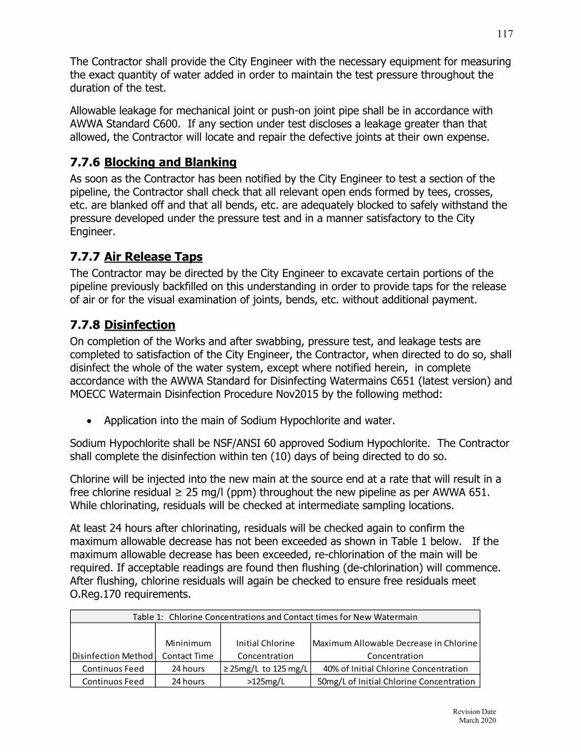
Revision Date March 2020
117
The Contractor shall provide the City Engineer with the necessary equipment for measuring the exact quantity of water added in order to maintain the test pressure throughout the duration of the test.
Allowable leakage for mechanical joint or push-on joint pipe shall be in accordance with AWWA Standard C600. If any section under test discloses a leakage greater than that allowed, the Contractor will locate and repair the defective joints at their own expense.
7.7.6 Blocking and Blanking As soon as the Contractor has been notified by the City Engineer to test a section of the pipeline, the Contractor shall check that all relevant open ends formed by tees, crosses, etc. are blanked off and that all bends, etc. are adequately blocked to safely withstand the pressure developed under the pressure test and in a manner satisfactory to the City Engineer.
7.7.7 Air Release Taps The Contractor may be directed by the City Engineer to excavate certain portions of the pipeline previously backfilled on this understanding in order to provide taps for the release of air or for the visual examination of joints, bends, etc. without additional payment.
7.7.8 Disinfection On completion of the Works and after swabbing, pressure test, and leakage tests are completed to satisfaction of the City Engineer, the Contractor, when directed to do so, shall disinfect the whole of the water system, except where notified herein, in complete accordance with the AWWA Standard for Disinfecting Watermains C651 (latest version) and MOECC Watermain Disinfection Procedure Nov2015 by the following method:
Application into the main of Sodium Hypochlorite and water.
Sodium Hypochlorite shall be NSF/ANSI 60 approved Sodium Hypochlorite. The Contractor shall complete the disinfection within ten (10) days of being directed to do so.
Chlorine will be injected into the new main at the source end at a rate that will result in a free chlorine residual ≥ 25 mg/l (ppm) throughout the new pipeline as per AWWA 651. While chlorinating, residuals will be checked at intermediate sampling locations.
At least 24 hours after chlorinating, residuals will be checked again to confirm the maximum allowable decrease has not been exceeded as shown in Table 1 below. If the maximum allowable decrease has been exceeded, re-chlorination of the main will be required. If acceptable readings are found then flushing (de-chlorination) will commence. After flushing, chlorine residuals will again be checked to ensure free residuals meet O.Reg.170 requirements.
Disinfection Method
Mininimum
Contact Time
Initial Chlorine
Concentration
Maximum Allowable Decrease in Chlorine
Concentration
Continuos Feed 24 hours ≥ 25mg/L to 125 mg/L 40% of Initial Chlorine Concentration
Continuos Feed 24 hours >125mg/L 50mg/L of Initial Chlorine Concentration
Table 1: Chlorine Concentrations and Contact times for New Watermain
Revision Date March 2020
118
Example 1
With an initial chlorine concentration of 50mg/L, the maximum allowable decrease in chlorine concentration is 40% of 50mg/L, or 20 mg/L. Therefore, at least 30 mg/L of chlorine must be present after 24 hours.
Example 2
With an initial chlorine concentration of 150mg/L, the maximum allowable decrease in chlorine concentration is 50mg/L, because 40% of 150mg/L is greater than the maximum allowable decrease of 50mg/L. Therefore, at least 100 mg/L of chlorine must be present after 24 hours.
7.7.9 Declorinating All water wasted shall be discharged into the stormwater system and shall be neutralized to provide a total chlorine residual of less than 0.2 mg/l. Acceptable dechlorination/ neutralizing agents are sodium thiosulphate and hydrogen peroxide. Neutralizing agent shall be noted in the commissioning plan. The Contractor or Consultant will monitor the discharge of waste water. Should tests show a residual greater than 0.2 mg/l, the discharge shall be ceased immediately and the procedure modified to meet less than the 0.2 mg/l objective. Where detrimental effects may be suffered by plants and/or animals in the natural environment, the wasted water shall be neutralized to provide a total chlorine residual of less than 0.002 mg/l (2 ppb) (Provincial Water Quality Objective) at the outfall. The Contractor or Consultant will monitor the discharge of waste water. Should tests show a residual greater than 0.002 mg/l, the discharge shall be ceased immediately, the City Engineer shall be notified, and the procedure modified to meet the less than 0.002 mg/l objective. Sites within 100m of natural drainage, or with direct discharge to a water body, should be considered high risk. In such instances, the City Engineer may request a dechlorination plan along with contingency and mitigation plans in the event that the chlorine residuals exceed those specified.
The Contractor may be permitted to discharge waste water into the sanitary collection system only upon approval of the City Engineer. The Contractor will need to demonstrate that there are no other available options. The City Engineer may direct the Contractor to de-chlorinate to a specified chlorine residual prior to discharge or limit the discharge rate to the sanitary collection system. The Contractor or Consultant will monitor the discharge of wastewater to ensure the chlorine residual and discharge limits are not exceeded.
The City Engineer reserves the right to direct the Contractor to dispose of wasted water to a sanitary sewer with chlorine residual not to exceed a specified limit or discharge rate.
The Contractor shall flush every part of the water system including fire hydrant leads, stubs for future watermains and services to remove all super chlorinated water.

Revision Date March 2020
119
7.7.10 Chlorine Residual & Bacteriological Sampling Procedure Prior to the commencement of chlorination residual and bacteriological testing, the Contractor shall submit a sampling plan and drawing detailing the source water location, final connection locations and the sampling locations to the City Engineer for approval. The Contractor shall allow two (2) weeks for review and approval. Appropriate coding or labelling shall be provided on the plan and drawing to clearly correlate the sample results to the sampling locations. Before the watermain can be approved for connection to the existing water distribution system, two (2) consecutive rounds of water samples, taken at least 24 hours apart, shall pass both the chlorine residual and bacteriological standards outlined below for consecutive samples. Prior to chlorine residual and bacteriological testing, all other testing (i.e. hydrostatic, disinfection) shall be completed and any super-chlorinated water removed from all portions of the watermain system under consideration including fire hydrant leads, stubs, branches, services, etc.
The watermain test section shall not be disturbed or flushed during the period between the 1st and 2nd sampling rounds, except to obtain a water sample.
The watermain shall be continually pressurized from the start of bacteriological testing until the final connection to the existing system is undertaken.
Only after the tested watermain has passed all chlorine residual and bacteriological requirements and has been approved to be put into service by the City Engineer, shall the watermain be connected to the existing water distribution system.
After the completion of the final connection, the watermain shall be re-pressurized by the existing system as soon as possible.
The City Engineer may request additional bacteriological sampling after the final connection has been made as a precaution against or in response to possible contamination during the final connection.
Source Water The water used to conduct the chlorine residual and bacteriological testing shall be normal to the existing water distribution system. Should the Contractor elect to undertake a bacteriological sample of source water from a municipal system, the sample must be taken from the new watermain side of the backflow preventer. In the event that this sample is adverse, the City Engineer may undertake a sample of the municipal system to verify the results.

Revision Date March 2020
120
Sample Locations Chlorine residual and bacteriological testing samples shall be taken:
At the end of each branch or stub (excluding fire hydrants) At the end of services 100 mm or larger A maximum of every 350 metres along the watermain test section A maximum of 150m from the source water connection Any additional locations as required to ensure that adequate chlorination is achieved
(e.g. to ensure that both sides of a crescent are chlorinated) As directed by the City Engineer
Sampling of fire hydrant leads is not required unless the Contractor has elected or is requested to utilize a fire hydrant location to satisfy any of the above sampling location criteria. Regardless of whether fire hydrants are used for a sampling location, all fire hydrant leads shall be thoroughly flushed to remove debris and any super-chlorinated water.
In the event that the maximum distance criteria cannot be satisfied or if additional sampling points are required by the City Engineer, the Contractor may be directed by the City Engineer to install sampling taps on the watermain for the sole purpose of obtaining a water sample. During the completion of the final connection or after the watermain has been commissioned the Contractor shall remove the sampling line and replace the main stop with a plug. Stainless steel plugs must be installed on saddles and brass plugs for ductile iron.
All sampling ports shall be copper or stainless steel lines 25 mm or smaller and brought a minimum of 1.0m above the surface. The Contractor shall be available to operate underground valves as necessary during sampling.
Bacteriological Sampling After disinfection of the watermain, two consecutive samples 24 hours apart shall be taken by City of Stratford licensed water division personnel and sent for testing by a third party Laboratory approved by the City Engineer. Test results shall indicate that the water is of such a quality that meets Ministry of the Environments Water Distribution Bacteriological standards as per Regulation 170/03. If test results do not meet standards, swabbing, pressure testing, and disinfection will need to be performed again as directed by the City Engineer until the standards are met. At each sampling location, the water shall satisfy the bacteriological requirements as follows both Sampling Round 1 and 2: E.coli, Total Coliforms, & HPC.
Post Final Connection Bacteriological Testing Contractors are advised that the City Engineer has the authority to request a third round of water samples for bacteriological analysis after the final connection has been made to the existing water distribution system to confirm the continued quality of the water within a period of two (2) working days. In the event that adverse water samples occur, the City Engineer will direct the corrective actions to be taken. The Contractor shall cooperate and participate fully in the corrective actions at the Contractors expense.

Revision Date March 2020
121
In the event, the Contractor does not take appropriate measures to correct adverse water samples and/or at the discretion of the City Engineer, the new system may be isolated from the municipal water system and the Contractor will be required to provide two (2) consecutive rounds of chlorine and bacteriological to the standards set out to commission the new water system.
The inspector must inform the City Engineer if additional testing/flushing is required upon final connection (e.g. due to possible suspected contamination or unsanitary site).
7.7.11 Final Connection to Existing Water Distribution System Procedure After the pressure, leakage, chlorine residual and bacteriological tests have passed; the Contractor shall obtain written approval from the City Engineer to make the final watermain connection to the existing watermain distribution system. If a temporary water system has been installed, it shall not be removed until after the City Engineer has accepted the final connection of the new watermain to the existing municipal system and has authorized the removal of the temporary water system.
The Manager of Environmental Services or designate shall be contacted two (2) full working days prior to the final connection to determine if any special measures shall be taken and/or a City of Stratford Licensed Water Div. employee is required to oversee the works. The Contractor will be responsible for all costs for call outs of Municipal staff if the Contractor fails to notify the Municipality that the connection will not take place.
City of Stratford Licensed Water Div. personnel shall be present to witness the entire final connection process of the new watermain to the existing water distribution systems.
Watermains shall be cut back to remove all temporary taps. The Contractor shall disinfect the connection watermain as outlined below and shall, using all means possible, dewater the watermains and trench in a controlled manner to not allow backflow into the watermains. Upon final connection the contractor shall contact the municipality to flush water through a nearby municipally owned hydrant (contractor to provide a minimum 48 hour notice prior to final connection).
If trench water, dirt or debris has entered the watermain during the final connection the watermain shall be aggressively flushed and additional bacteriological samples shall be taken as directed by the City Engineer. The City Engineer reserves the right to request the above steps be taken regardless.
The Contractor shall submit written procedures for completing the final connection, including the method of dewatering to ensure the existing or new water system is not contaminated.
All procedures must comply with AWWA C651.

Revision Date March 2020
122
Connections Equal or Less than One Pipe Length For a final connection length equal to or less than one pipe length, the new piping, fittings and valves required for the connection shall be spray-disinfected and hand swabbed with a minimum 1% and maximum 5% solution of chlorine just prior to being installed. The Contractor shall ensure that the workers undertaking the disinfection process thoroughly wash their hands with soap and use hygienic practices. Connections Greater than One Pipe Length In the event that the final connection point of the new watermain to the existing watermain distribution system is in a location that requires a connection length greater than one pipe length. The new piping, fittings and valves required for the connection shall be assembled aboveground, disinfected and tested in accordance with AWWA 651. The connection piping shall satisfy the chlorine residual and bacteriological requirements outlined for new watermains. The pre-assembled watermain connection shall be drip tight. Only after satisfactory chlorine residual and bacteriological results have been achieved, shall the pre-assembled connection be installed. The pre-assembled watermain shall be maintained under pressure from the start of chlorine residual and bacteriological testing protocol until just prior to the installation. All caps shall be kept in place during the installation procedure until immediately prior to making the connection.
The Contractor shall not hand disinfect one pipe length at a time to circumvent the requirements to preassemble connection piping over one pipe length aboveground.
Should the Contractor find it necessary to deviate from the protocol as outlined in AWWA 651 and above, the Contractor shall submit a Connection Plan to the City Engineer for review and approval. The Contractor shall allow two weeks for review.
Tracer Wire During the final connection of the new watermain to the existing distribution system, the Contractor shall insure that the new tracer wire is connected to the existing tracer wire or Cad welded with a petrolatum protection to the metal watermain. Tracer Wire Conductivity Test After the installation of base asphalt or final grading, the Contractor shall demonstrate the integrity of the underground tracer wire by applying a conductivity signal and confirming the signal on all watermains and services. The intent of this test is to confirm that the tracer wire has been installed on all non-metallic watermains and services as specified. Specifically, the test shall demonstrate the integrity and continuity of the tracer on all watermains and services.
A continuity signal shall be applied to the tracer wire and the signal confirmed over the entire length of all tracer wire installed. The signal shall be detectable for a distance of at least 300m from either side of the signal connection point. At no time shall there be a break in the continuity of the tracer wire.
Revision Date March 2020
123
It shall be demonstrated that the tracer wire on the services is connected to the watermain tracer wire and that the service tracer wire is intact for the length of the service.
Acceptable means of undertaking the conductivity test include using traditional locating techniques and/or determining if a low voltage electrical current travels from the connection point to test points.
7.7.12 Valve Positioning The Contractor shall demonstrate that all valves, main line and service, are in the final positioning as outlined in the Contract Documents or as directed by the City Engineer.
Revision Date March 2020
124
Section 8 – Site Grading
8.1 Grading Requirements for Various Situations Grading in Plans of Subdivision, Plans of Condominium, Site Plans, and infill lots are to be designed by a Professional Engineer. All lot drainage shall conform to applicable stormwater management reports and City standards.
8.1.1 Subdivisions Developments created by a draft plan of subdivision shall conform to the following lot grading standards and will not adversely affect the abutting or adjacent properties.
8.1.2 Site Plans Developments subject to site plan approval are to be graded and drained internally or be in conformance to the approved Stormwater Management Master Plan. The site grading and drainage shall conform to the overall drainage pattern of the adjacent lands as certified by the design engineer at the time of the permit for each building. The proposed stormwater management system should not adversely affect adjacent properties as per the OBC.
8.1.3 Severances, Lifting of Part Lot Control, Infill Lots Developments created by severance, lifting of Part Lot Control and infill lots for residential lots shall conform to the lot grading standards of a plan of subdivision and are not to adversely affect the abutting and / or adjacent properties.
8.1.4 Blocks Developments on blocks within registered plans of subdivision are subject to site plan approval. Drainage and grading of such blocks shall conform to the accepted overall subdivision design and stormwater management report and shall be certified by the site design engineer. The Developer shall be responsible for the grading of the blocks until assumption of the subdivision. The Developer and their Consultant shall be responsible for approval and certification of the grading as outlined in the Subdivision Agreement. In addition to the grading requirements specified below, the following criteria shall apply:
All blocks shall be sodded using 100mm topsoil and No. 1 Nursery sod for 5m width around their perimeter when base course asphalt is placed, the remainder of the block shall be at minimum seeded using 100mm topsoil, with seed of the quality and quantity approved by the City, and mulch.
The Developer shall be responsible to maintain the block until a building permit is granted, or in the case of blocks to be deeded to the City, until the subdivision is assumed.
Seeding specifications for sport fields and parks is 6lbs per 1000sq. ft ( 3kgs per 100m sq.). Seed is to be split seeded in two directions.( Therefore half rate each direction). Seed shall be 60% Kentucky Blue grass and 40% perennial rye grass mix.

Revision Date March 2020
125
8.1.5 Capital Projects When grading is required, the designer shall determine match points that appear to naturally blend proposed design grades with existing topography. Major overland flow routes are to be maintained. Consideration shall be given to transitions with intersecting streets, driveway profiles, drainage, utilities, existing retaining walls, potential impacts on trees and other landscaping features. Wherever possible, the designer shall take every opportunity to eliminate or reduce the size of existing retaining wall owned and maintained by the City. Consideration should also be given to maintenance and aesthetics of grassed areas such as lawns and boulevard areas. Grades should not be altered around trees on the basis of 30cm of distance from the stem for each 3cm of trunk diameter at breast height 1.5m above ground. Maximum slopes shall be 4:1 unless authorized in writing by the City Engineer. Proposed driveway and ramp grades shall not exceed 8% unless approved by the City. Pedestrian access routes shall not exceed 5% unless approved by the City. Grading to be incompliance with the Ontario Building Code and the Accessibility for Ontarians with Disabilities Act (AODA).
8.1.6 Variations / Modifications There will be site specific situations where all criteria may not apply. Proposed grading that does not conform to the appropriate grading requirement standard will be reviewed taking into account the mitigating circumstances that require the proposed variations or modifications. Before such work can completed approval is first required by the City Engineer.
8.2 Overland Flow Routes As storm sewer systems (referred to as the minor system) are designed to accommodate storm runoff from the 5-year storm event, the road and lot grading design (referred to as the major storm system), must be designed to accommodate runoff from storm events that exceed the design capacity of the storm sewer system. These allowances, in the form of major overland flow routes, shall provide for the effective routing of major overland storm flow to an acceptable overland flow outlet location and shall be contained within either the road right-of-way or by easements. When designing overland flow routes, the following criteria shall apply:
Major overland flow routes are preferred within the road allowance. Major overland flow routes are generally to follow low areas in subdivision grading
and be in compliance with an accepted SWM report. Under a 250 year design event the maximum depth of water at gutters at sags on
roads is 400mm. The product of flood depth at the gutter multiplied by the flow velocity shall be less
than 0.65m2/s. Building opening elevations adjacent to overland flow routes on roadways shall be
at least 400mm above the road centreline elevation.

Revision Date March 2020
126
Building opening elevations adjacent to overland flow routes through lots or blocks shall be at least 450mm above the overland flow route elevation (no window wells, or other openings).
Ground elevations at buildings abutting overland flow routes are to be 225mm above the elevation of the overland flow route.
The maximum ponding permitted at rear yard catchbasins is 350mm. The maximum ponding permitted at parking areas in multi-family, commercial and
institutional blocks is 300mm. Accommodate all overland flow routes into a stormwater management facility if
applicable. Show existing and proposed major overland flow route directional arrows on all
grading drawings. On local roads, flow should not overtop the curbs (except at sags) On collector roads, 1 lane should be left free from flooding. On arterial roads, 1 lane should be left free from flooding in each direction. Flow should not cross roads except for major storms (greater than 1:10 year). Low points along the road grade should not exist unless the low points are
conveying flow to the major system. Where possible, the major storm runoff should be conveyed to a watercourse or a
major channel at regular intervals along the road.
8.3 Grading Design Standards
8.3.1 Drainage Generally, the front yards of all lots shall be graded to drain towards the street. All boulevards are to be graded with a constant slope from the curb to the face of
sidewalk or to the street limit where there is no sidewalk (Minimum slope to be 2.0 percent and the maximum slope to be 5.0 percent).
All rear yard drainage is to be directed away from the houses in defined swales which outlet at the curb or a catchbasin.
Drainage from impervious areas on lots in a new subdivision is not to flow across existing lots abutting the new subdivision.
Drainage from single-family and semi-detached lots is not to drain onto Multi-family, Commercial or Institutional blocks (with the exception of major overland flow routes).
All multi-family, commercial and institutional block drainage is to be self-contained. Where a new subdivision abuts an existing development or undeveloped land, the
existing ground elevations at the common property line are to remain unchanged and existing drainage of abutting lands is not to be disturbed, or obstructed, unless written permission is granted by the current affected land owner.
Localized surface drainage from abutting properties, to be developed in future, may be discharged onto proposed lots in a subdivision.
The lot grading design shall provide for drainage problems on adjacent property that can be best resolved by permitting drainage through the subdivision.
Identify existing vegetation and set grades to retain where possible. The grade immediately adjacent to houses shall be a minimum of 150mm above the
invert of adjacent swales.

Revision Date March 2020
127
8.3.2 Slopes All lot surfaces shall be built to a minimum grade of 2% and a maximum grade of
10%. Boulevards shall have a minimum slope of 2% and a maximum slope of 5%. The minimum driveway grade shall be 1%; the maximum grade permissible shall be
8%, except where used as the sole pedestrian access, then a maximum grade of 5% applies as per AODA.
The maximum slope on all embankments and terraces shall be 3:1 (4:1 preferred). Berms shall have a maximum slope of 3:1 (4:1 preferred).
8.3.3 Swales Drainage flows that are carried around houses are to be confined in defined swales,
located as far from the house as possible. Minimum slope for swales shall be 2.0%. Where several lots drain through a swale to a rear yard catchbasin on private
property, a minimum 3.0m wide easement in favour of the City shall be provided for the CB and lead.
The maximum flow allowable to any side yard swale shall be that from the two adjacent lots plus that from two additional lots with a total area not exceeding 0.2 ha.
The maximum number of rear lots contributing to a rear yard swale shall be that of four rear yards.
The maximum length of a rear yard swale between outlets shall be 60 metres. Where rear yard swales are not situated on a lot line and provide drainage for more
than one lot, the swale must be located within a 3.0 metre drainage easement in favour of the City over the total length.
Minimum depth of any swale to be 150mm. Maximum depth of rear yard swales to be 600mm. Maximum depth of side yard swales to be 400mm. Maximum side slope on any swale to be 3:1. All side yard swales shall be located on the common lot line between adjacent lots. Rear yard swales shall be located on the common lot line between adjacent lots
where possible.
8.3.4 Catchbasins Rear lot catchbasins shall be eliminated wherever possible. Maximum total number of lots drained by a rear lot CB shall be eight. Where rear lot catchbasins are used all structures shall be protected from flooding if
the inlet is blocked or surcharged by a major storm event. Front yard catchbasins are not permitted, except in unusual circumstances. No surface ponding is allowed during a 5-year design storm event. Rear yard catchbasins and outlet pipes are to be located entirely on the same lot
and shall be located 0.6 metre from the lot line, within a minimum 3.0m easement in favour of the City. Refer to Std Dwg. 32 for additional information.

Revision Date March 2020
128
8.3.5 Retaining Walls Retaining walls shall be constructed according to the following.
Where retaining walls are required they shall be constructed on the higher lot such that the wall and tie-back do not cross property lines.
Retaining wall design and construction shall be certified by the Engineer. Retaining walls shall be constructed on private property, not on property to be
assumed by the City. In some cases, a retaining wall may require a building permit.
8.4 Subdivision Lot Grading Plans Grading plans are to be drawn to a minimum scale of 1 to 500 showing existing contours established from a topographic survey of pre-development conditions. The grading plans shall indicate but not be limited to the following:
North arrow Street names Existing contours extended outside the subject lands enough to determine the
existing drainage pattern; Driveway locations and building envelopes; Centre line elevations of existing roads at 20m intervals; Elevations at existing trees, structures, watercourses, etc.; Proposed elevations of roads at 20m intervals; Proposed elevations at front and rear building envelope; Proposed elevations at the corners of each lot and block; Proposed elevations of all highpoints and lowpoints on lots and roads; Proposed elevations of swales, rear lot catchbasins and such facilities as may be
necessary to drain lands adjacent to the subdivision; Gutter drainage details for turning radii, cul-de-sacs and intersections; Direction of the surface run-off by means of arrows; Proposed elevations of back of sidewalk opposite each lot or block corner as
required; Building setbacks for rear yard catchbasin leads; Proposed 0.5m contours for grading within large blocks and parks; Proposed grades for major and minor overland flow routes; Lot fabric of subject lands including lot, block and easement description, lot and
block frontages, easement widths; Physical structures such as fencing, retaining walls, headwalls, etc.; Elevations for proposed and existing catchbasin lids; Maintenance holes and fire hydrants; Sidewalks, sidewalk ramps and pedestrian walkways; Steep slope lines; Sediment and erosion control measures.
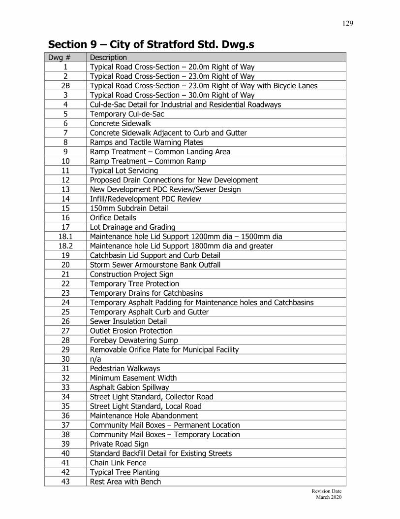
Revision Date March 2020
129
Section 9 – City of Stratford Std. Dwg.s Dwg # Description
1 Typical Road Cross-Section – 20.0m Right of Way2 Typical Road Cross-Section – 23.0m Right of Way2B Typical Road Cross-Section – 23.0m Right of Way with Bicycle Lanes 3 Typical Road Cross-Section – 30.0m Right of Way4 Cul-de-Sac Detail for Industrial and Residential Roadways 5 Temporary Cul-de-Sac6 Concrete Sidewalk 7 Concrete Sidewalk Adjacent to Curb and Gutter8 Ramps and Tactile Warning Plates9 Ramp Treatment – Common Landing Area10 Ramp Treatment – Common Ramp11 Typical Lot Servicing 12 Proposed Drain Connections for New Development13 New Development PDC Review/Sewer Design14 Infill/Redevelopment PDC Review15 150mm Subdrain Detail16 Orifice Details 17 Lot Drainage and Grading
18.1 Maintenance hole Lid Support 1200mm dia – 1500mm dia 18.2 Maintenance hole Lid Support 1800mm dia and greater19 Catchbasin Lid Support and Curb Detail20 Storm Sewer Armourstone Bank Outfall21 Construction Project Sign22 Temporary Tree Protection23 Temporary Drains for Catchbasins24 Temporary Asphalt Padding for Maintenance holes and Catchbasins 25 Temporary Asphalt Curb and Gutter26 Sewer Insulation Detail27 Outlet Erosion Protection28 Forebay Dewatering Sump29 Removable Orifice Plate for Municipal Facility30 n/a 31 Pedestrian Walkways 32 Minimum Easement Width33 Asphalt Gabion Spillway34 Street Light Standard, Collector Road35 Street Light Standard, Local Road36 Maintenance Hole Abandonment37 Community Mail Boxes – Permanent Location38 Community Mail Boxes – Temporary Location39 Private Road Sign 40 Standard Backfill Detail for Existing Streets41 Chain Link Fence 42 Typical Tree Planting 43 Rest Area with Bench

Revision Date March 2020
130
Dwg # Description W1 Watermain Bedding DetailW2 Standard 15 cm Hydrant & ValveW3 Standard 50 mm Blow-off InstallationW4 Standard Mechanical Joint Offset installation using retainer glands W5 Standard Valve Rod Extension piece for 10 cm and larger valves
W6-C Standard Copper Water ServiceW6-P Standard PEXa Water ServiceW7 Standard water service box installation 25 to 50mmW8 Types of Thrust RestraintsW9 Typical Temporary Connection for WatermainsW10 Installation of Water Meters – Residential & CommercialW11 Installation of Water Meters - Commercial & Industrial Compound MetersW12 Watermain Insulation DetailW13 Installation of Water Meters – Residential & Commercial
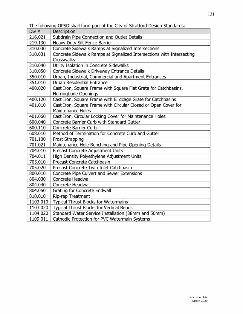
Revision Date March 2020
131
The following OPSD shall form part of the City of Stratford Design Standards: Dw # Description 216.021 Subdrain Pipe Connection and Outlet Details219.130 Heavy Duty Silt Fence Barrier310.030 Concrete Sidewalk Ramps at Signalized Intersections310.031 Concrete Sidewalk Ramps at Signalized Intersections with Intersecting
Crosswalks 310.040 Utility Isolation in Concrete Sidewalks310.050 Concrete Sidewalk Driveway Entrance Details350.010 Urban, Industrial, Commercial and Apartment Entrances351.010 Urban Residential Entrance400.020 Cast Iron, Square Frame with Square Flat Grate for Catchbasins,
Herringbone Openings 400.120 Cast Iron, Square Frame with Birdcage Grate for Catchbasins 401.010 Cast Iron, Square Frame with Circular Closed or Open Cover for
Maintenance Holes 401.060 Cast Iron, Circular Locking Cover for Maintenance Holes600.040 Concrete Barrier Curb with Standard Gutter600.110 Concrete Barrier Curb 608.010 Method of Termination for Concrete Curb and Gutter701.100 Frost Strapping 701.021 Maintenance Hole Benching and Pipe Opening Details704.010 Precast Concrete Adjustment Units704.011 High Density Polyethylene Adjustment Units705.010 Precast Concrete Catchbasin705.020 Precast Concrete Twin Inlet Catchbasin800.010 Concrete Pipe Culvert and Sewer Extensions804.030 Concrete Headwall 804.040 Concrete Headwall 804.050 Grating for Concrete Endwall810.010 Rip-rap Treatment 1103.010 Typical Thrust Blocks for Watermains1103.020 Typical Thrust Blocks for Vertical Bends1104.020 Standard Water Service Installation (38mm and 50mm)1109.011 Cathodic Protection for PVC Watermain Systems

APPENDIX
A

City of Stratford
WATER DIVISION
SERVICE REGULATIONS
Revised: January 2016

Corporation of the City of Stratford WATER DIVISION SERVICE REGULATIONS
1
Form 1-74 Revisions: Sept. 1978, June 1980,
March 1988, Jan. 1991, Nov. 1996, Oct. 1999 Feb. 2002. Jan. 2009
Jan. 2010 Dec. 2015
Corporation of the City of Stratford Water Division
TABLE OF CONTENTS
Section “A” GENERAL
1. Definitions 2. Application for Service 3. Location of Service 4. Frozen Water Services 5. Remote Water Meter 6. Responsibility of Builder
Section “B” RESIDENTIAL SERVICES
1. Service Size - New Dwelling Units 2. Application for Service 3. Adjustment of Payment 4. Replacement of Service 5. Limit of Service 6. Remote Water Meter 7. Residential Sprinkler Services
Section “C” COMMERCIAL SERVICES
1. Service Size 2. Application for Service 3. Limit of Service 4. Adjustment of Payment 5. Remote Water Meter 6. Backflow Protection
Section “D” COMMERCIAL/INDUSTRIAL SPRINKLER SERVICES
1. Service Size 2. Application for Service 3. Limit of Service 4. Adjustment of Payment 5. Fire Department 6. Backflow Protection

Corporation of the City of Stratford WATER DIVISION SERVICE REGULATIONS
2
Table of Contents - cont’d: Section “E” HYDRANT REGULATIONS
1. Operation of Hydrants 2. Public Hydrants 3. Private Hydrants 4. Hydrant Connections 5. Hydrants Used by Board of Works
Section “F” METER REGULATIONS
1. Location 2. Connections 3. Meter Chambers 4. Meters Larger than 2” 5. Meter Maintenance
Section “G” MAINS & VALVES
1. General 2. Double Service - Backflow Prevention
Section “H” DRAWINGS 1. Regulations Regarding Installations of Water Meters 2. Remote Water Meter Register Installation

Corporation of the City of Stratford WATER DIVISION SERVICE REGULATIONS
3
Section “A”
GENERAL
1. DEFINITIONS The City of Stratford is hereinafter referred to as the City. Plumbing Contractors performing work within the limits of the City of Stratford as the Contractor. Rates charged for water consumption will be in accordance with rates set by the City from time to time. Rates charged for water consumed in commercial, industrial and apartment buildings etc., as General Rates. 2. APPLICATION FOR SERVICE Water service will be supplied by the City upon written application to the City by the customer as covered under Section B (2), Section C (2) and Section D (2). 3. LOCATION OF SERVICE (Revision 02/02) Water services may not be laid in the same trench as other services unless a 2.5 metre space is provided between services, from watermain to inside the building wall. 4. FROZEN WATER SERVICES (Revision 12/15) Water services between the watermain and the exterior wall of customer’s premises which have been frozen will be thawed without charge the first time (unless previously notified to let water run), but a service charge will be levied if water service freezes again or after notification to let water run. 5. REMOTE WATER METER An existing resident with an inside electric meter may obtain a remote water meter from the City for a fee of twenty-five dollars ($25.00). This remote water meter will be installed by the City. For all new residences a twenty-five dollar ($25.00) fee for a remote water meter will apply. Wire may be picked up at Festival Hydro’s Service Centre at 161 Wellington Street, and installed by the electrical contractor.

Corporation of the City of Stratford WATER DIVISION SERVICE REGULATIONS
4
Section “A” Remote Water Meter - cont’d An existing resident with an outside electric meter may obtain a remote water meter from the City. The City will install this remote water meter. When a customer installs his electric meter outside on an existing dwelling the water meter will be moved outside at no charge. 6. RESPONSIBILITY OF BUILDER (Revised 10/99) It is the responsibility of the builder to supply measurement from the foundation wall for each service shut-off. The curb box will be checked by the City before the water is turned on. Water will not be turned on until a water meter is installed. It is the builder’s responsibility to ensure that the water meter is not damaged during construction.
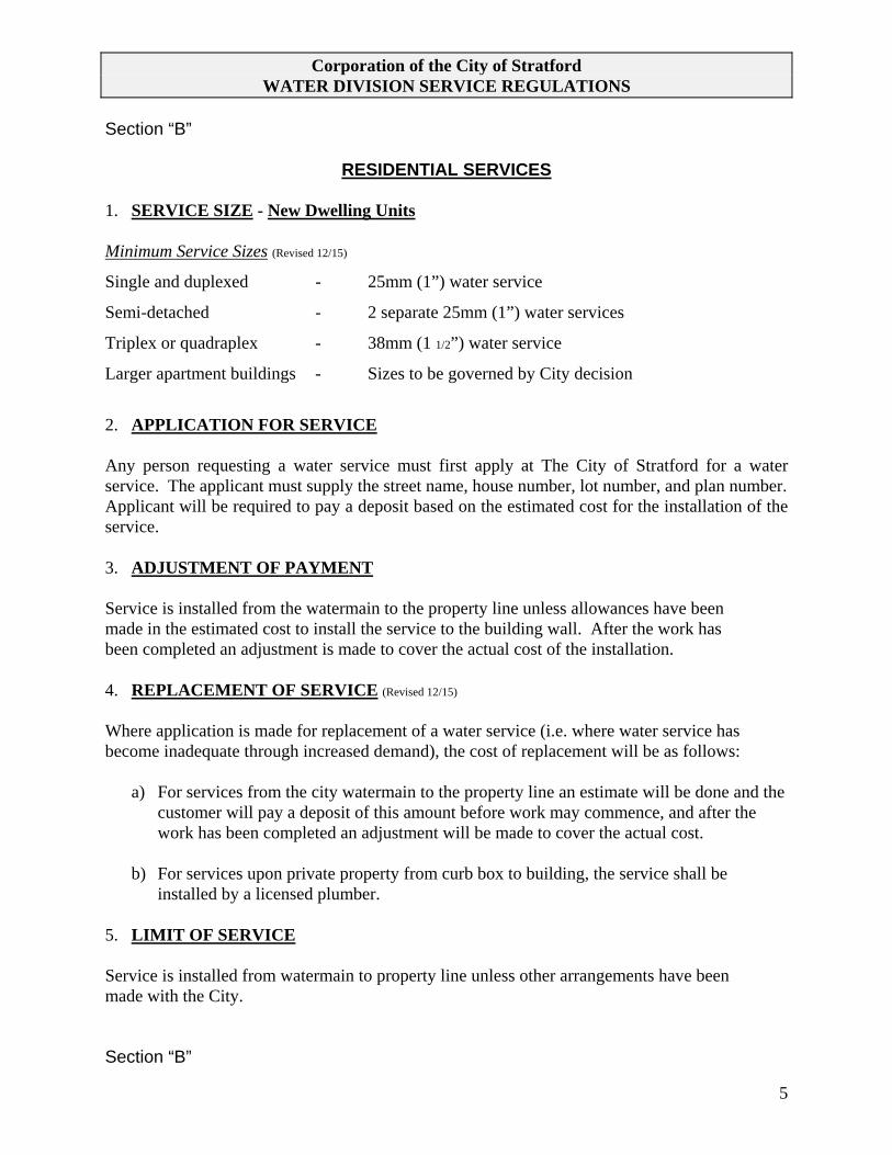
Corporation of the City of Stratford WATER DIVISION SERVICE REGULATIONS
5
Section “B”
RESIDENTIAL SERVICES
1. SERVICE SIZE - New Dwelling Units Minimum Service Sizes (Revised 12/15)
Single and duplexed - 25mm (1”) water service
Semi-detached - 2 separate 25mm (1”) water services
Triplex or quadraplex - 38mm (1 1/2”) water service
Larger apartment buildings - Sizes to be governed by City decision
2. APPLICATION FOR SERVICE Any person requesting a water service must first apply at The City of Stratford for a water service. The applicant must supply the street name, house number, lot number, and plan number. Applicant will be required to pay a deposit based on the estimated cost for the installation of the service. 3. ADJUSTMENT OF PAYMENT Service is installed from the watermain to the property line unless allowances have been made in the estimated cost to install the service to the building wall. After the work has been completed an adjustment is made to cover the actual cost of the installation. 4. REPLACEMENT OF SERVICE (Revised 12/15) Where application is made for replacement of a water service (i.e. where water service has become inadequate through increased demand), the cost of replacement will be as follows:
a) For services from the city watermain to the property line an estimate will be done and the customer will pay a deposit of this amount before work may commence, and after the work has been completed an adjustment will be made to cover the actual cost.
b) For services upon private property from curb box to building, the service shall be
installed by a licensed plumber. 5. LIMIT OF SERVICE Service is installed from watermain to property line unless other arrangements have been made with the City. Section “B”

Corporation of the City of Stratford WATER DIVISION SERVICE REGULATIONS
6
6. REMOTE WATER METER All new services will require a remote water meter, which is obtained from the City for a charge of twenty-five dollars ($25.00). See Section “A” (5). 7. RESIDENTIAL SPRINKLER SERVICES (Revised 01/09) Residential sprinkler services shall be installed after the water meter and must have testable backflow device.

Corporation of the City of Stratford WATER DIVISION SERVICE REGULATIONS
7
Section “C”
COMMERCIAL SERVICES
1. SERVICE SIZE See Section “B” (1) for service size requirements. 2. APPLICATION FOR SERVICE Any person requesting a water service must first apply at the City for a water service. This applicant must supply the street name, municipal number, lot and plan number. An estimated cost will be made and the customer will be required to pay a deposit of this amount before work may commence. After the work has been completed an adjustment will be made to cover the actual cost. See Section “F” (4). 3. LIMIT OF SERVICE Service is installed from the watermain to the property line unless allowances have been made in the estimated cost to install the service to the building. 4. ADJUSTMENT OF PAYMENT Upon completion of the work the City will make an adjustment to the applicant for over or under payment on deposit to cover the actual cost of the installation. 5. REMOTE WATER METER (Revised 11/96) If electrical is outside a remote water meter is required. There is an additional cost of $25.00 for new installations. See Section “A” (5). All new services will require a remote water meter which is to be obtained from the City for a fee of twenty-five dollars ($25.00). See Section “A” (5). The water meter will be remoted to the location of the electric meter. 6. BACKFLOW PROTECTION (Revised 11/96) All new commercial services must have backflow prevention. 7. CROSS CONNECTIONS (Revised 02/02)
If a cross connection is discovered, the owner will be required by the City to remove the cross connection immediately or be subjected to a loss of service.

Corporation of the City of Stratford WATER DIVISION SERVICE REGULATIONS
8
Section “D”
COMMERCIAL/INDUSTRIAL SPRINKLER SERVICES
1. SERVICE SIZE Applicant shall first inquire from the Engineering Department as to the feasibility of installing a sprinkler service. 2. APPLICATION FOR SERVICE Applicant shall apply at the City offices. An estimated cost will be given and a deposit of this amount is required before work can commence. 3. LIMIT OF SERVICE (Revised 02/02) Sprinkler service will be installed from the city watermain to the property line. The owners must have the service properly valved so that domestic service and sprinkler service can be isolated independently outside the building wall. 4. ADJUSTMENT OF PAYMENT Upon completion of work the City will make an adjustment to applicant for over or under payment on deposit to cover the actual cost of the installation. 5. FIRE DEPARTMENT All sprinkler service sizes and plans must be approved by the Stratford Fire Department. 6. BACKFLOW PROTECTION (Revised 11/96) Sprinkler service must have backflow protection.

Corporation of the City of Stratford WATER DIVISION SERVICE REGULATIONS
9
Section “E”
HYDRANT REGULATIONS
1. OPERATION OF HYDRANTS Hydrants shall be operated by City Water Division personnel and those appointed by the City. 2. PUBLIC HYDRANTS Location of all public hydrants shall be approved by the City of Stratford Fire Chief and all installations shall include an isolating valve and valve box. 3. PRIVATE HYDRANTS The City’s Engineering Department shall be notified of the installation of any private hydrant. The said City shall in no way be liable for private hydrants, or for maintaining them. 4. HYDRANT CONNECTIONS Contractors shall be allowed to obtain water from fire hydrants at the current rate, by use of a portable water meter with a back flow device installed by the City (where practical). A deposit will be required to be paid at Festival Hydro office before meter is installed. 5. HYDRANTS USED BY PUBLIC WORKS Hydrants that may be used by the Public Works Department will be identified with a black circle. Other hydrants may NOT be used without previous consent from the Water Division.

Corporation of the City of Stratford WATER DIVISION SERVICE REGULATIONS
10
Section “F”
METER REGULATIONS
1. LOCATION (Revised 02/02) Water meters must be accessible at all times and all valves must be in working order. Water meter sizes 5/8” to 2” shall be installed horizontal and not more than 18” from the floor with a minimum of 4” from the wall, and must have easy access for changing and reading purposes (see drawing). Water meters shall be grouped. The water meter size is to be approved by the City Water Division. 2. CONNECTIONS All water meters 1 ½” and over must have bypasses as listed below. All water meters under 2” shall have a ball valve on each side of the meter (see drawing). 1 1/2” & 2” meters - 1” bypass
Larger than 2” meter - 2” bypass
3. METER CHAMBERS Meter chambers will not be used unless special permission is obtained from the City’s Engineering Section. 4. METERS LARGER THAN 2” (Revised 10/99) Meters larger than 2” shall be provided by the City, and paid for by the customer as per the Site Plan Servicing Agreement. Sizes to be approved by the Water Division. 5. METER MAINTENANCE All water revenue meters will be serviced by the City at its expense.

Corporation of the City of Stratford WATER DIVISION SERVICE REGULATIONS
11
Section “G”
MAINS & VALVES
1. GENERAL No person or persons except the City Water Division, or those they authorize, shall open or close any valve in the distribution mains or molest or interfere with them in any manner. For installations of water mains the City’s General Specifications must be followed. 2. DOUBLE SERVICE-BACKFLOW PREVENTION (Revised 01/10) Every owner of any premises upon which is situated an industrial, commercial or
institutional building which is supplied with water from the City’s water supply system shall ensure that under no condition shall there be any backflow of unpotable or contaminated water into the potable drinking water lines on said premises or into the City’s water supply system. Where air gaps are not possible in the connecting of the potable water supply onto contaminated systems, backflow preventers designed to the degree of contamination shall be installed.
Backflow preventers shall be installed, tested and maintained by qualified persons only. An employee or authorized agent of the City may enter any
industrial/commercial/institutional premise at any reasonable time to request a test of the functionality of the backflow preventer.
Every owner of a backflow preventer shall comply with the City of Stratford Cross
Connection By-law 50-2004 as amended.

APPENDIX
B

COMMISSIONING PLAN TEMPLATE (For Reference)
PROJECT NAME FROM – TO / DESCRIPTION
CITY OF STRATFORD CONTRACT No. XXX
WATERMAIN COMMISSIONING PLAN
Note on use of this template: This template attempts to provide a format and show example information needed for a wide range of watermain projects from a trunk main to a subdivision to a large water service. The user should edit, add or delete information and/or sections as may suit the particular application while still providing an adequate description of the work to be undertaken so that a timely review may be completed by the Contract Administrator/Chief Municipal Engineer. In Stage 1, the criteria is included for each section ahead of the project calculations as a reminder of the requirements to be met. The Plan should be submitted prior to watermain installation so that source requirements and sampling points are known which may avoid the need to change construction plans or re-excavate a main to install an intermediate sampling point.
The following plan for temporary connection, swabbing, disinfection and testing of the watermain meets the requirements of the City of Stratford Water Specifications and Engineering Standards. A sketch of the site is attached showing the system layout with source and sampling locations identified.
STAGING
In general, the new water system will be pressure and leakage tested in xx stage(s) comprised of the following areas:
Stage Street From To
1
2
Street A Street B Street C
Exist St Street A Street B
Street B Street C Street D
Street D Street C Sta. x+xxx
STAGE 1
1 A. SAMPLE LOCATIONS
Samples will be taken from existing system facilities like service laterals and air relief valve fittings, or temporary service laterals where necessary on long runs. When plugging temporary laterals, the mainstop will be removed and replaced with a stainless steel plug in the stainless steel saddle. A drawing shall be provided (Hand or Digital)
Sample
Max. Distance from Source or Previous
Point Identifier
Street
Station
Sample Location (m)
Type of Sample Port
A
Street A
0+000
Source
D/S temporary connection B 0+140 140 Temp copper off mainstop for air relief valve C 0+490 350 25 mm Service
D
Street B
2+168
180
Temp 19 mm service (to be plugged after testing) E 2+480 312 Temp copper off mainstop in VC

1 B. TEMPORARY CONNECTION / WATER SOURCE
The watermain stage under test will be connected to the source as detailed below. A tested and certified backflow preventer will be located in each filler line to prevent a possible reverse flow and contamination of the in-service source main. Any samples taken at the source end of the new main will come from the downstream side (new main side) of the backflow preventer.
Source and Filling
Street: Name Location (Station. /intersection) 0+000 Source main size: 300 mm No. of fill lines: 1 Fill line size: 50 mm
1 C. SWABBING
Swabbing will be done wet and a minimum 3 swabs will pass through all new mains. Water will be added to the pipelines ahead of the swabs by filling at xxxx (e.g. first filling from the source connection prior to launching the swabs, or adding water via the sample line at Sta. xxx, etc.). Swabs will be launched, travel at adequate cleaning speeds, and be retrieved as follows:
Launch Location Pipe Swab Retrieval Location Street Station Type Size Size Velocity Street Station Type mm mm m/s Street A 0+000 Swab port 300 350 0.60 Street A 0+490 Open pipe Street B 2+000 Insert in new pipe 150 200 0.85 Street B 2+480 Hydrant
1 D. HYDROSTATIC TESTING
As a minimum, the hydrostatic test pressure of 1035 kPa (150 psi) will be applied to all points of the watermain within the test section, including high points. (2 hour test) AWWA C600 - Metric Units Lm= SD√P 794,797 Lm = testing Allowance (makeup water), in litres per hour. S = length of pipe tested, in meters D = nominal diameter of the pipe, in millimeters P = average test pressure during hydrostatic test, in kilopascals. Leakage calculation: Length and sizes of test section: 490 m of 300 mm
312 m of 150 mm Allowable leakage vol for stage: 7.84 litres/hour

1 E. DISINFECTION and TESTING
Chlorine will be injected into the new main at the source end at a rate that will result in a free chlorine residual ≥ 25 mg/l (ppm) throughout the new pipeline as per AWWA 651. While chlorinating, residuals will be checked at intermediate sampling locations. At least 24 hours after chlorinating, residuals will be checked again to confirm the maximum allowable decrease has not been exceeded as shown in Table 1. If the maximum allowable decrease has been exceeded re-chlorination of the main will be required. If acceptable readings are found then flushing (de-chlorination) will commence. After flushing, chlorine residuals will again be checked to ensure free residuals meet O.Reg.170 requirements.
Sodium Hypochlorite NSF/ANSI 61 Approved: xx% Brand Name
City of Stratford Licensed Water personnel will take all Bacteriological Samples. After the first round of samples have been taken, the test section will be shut down (ie. no flow of water). After a minimum of 24 hours, the second set of Bacteriological samples & chlorine residuals at each sampling point will again be tested. Once results are received from the 3rd party Laboratory and results are approved by the City of Stratford Water Div. The Final connection can be made.
1 F. FINAL CONNECTION
Final connection will be made in dry conditions in the presence of the City of Stratford Water personnel. All required pipe and fittings will be swabbed with a minimum 1% to maximum 5% solution of chlorine prior to installation. Upon completion of the connection, the main will be flushed from the hydrant / service at Sta.x+xxx to rid the main of high chlorine. If some occurrence during final connection indicates that the main may have been contaminated, a third round bacteriological sample will be taken.
Type of Connection: remove cap/cut-in tee and sleeve/tapping sleeve and valve/other Gap to connect: 3.5 m Connection details: remove exist cap, install 150mm pipe and solid sleeve
Subsequent to acceptable bacteriological testing and final connection, the municipality will be called to open the new main to regular service.
\
Disinfection MethodMininimum
Contact TimeInitial Chlorine Concentration
Maximum Allowable Decrease in Chlorine Concentration
Continuos Feed 24 hours ≥ 25mg/L to 125 mg/L 40% of Initial Chlorine ConcentrationContinuos Feed 24 hours >125mg/L 50mg/L of Initial Chlorine Concentration
Table 1: Chlorine Concentrations and Contact times for New Watermain

STAGE 2
2 A. SAMPLE LOCATIONS
Sample
Max. Distance from Source or Previous
Point Identifier
Street
Station
Sample Location (m)
Type of Sample Port
F
Street C
3+000
Source G 3+120 120 Temp copper off mainstop for air relief valve H 3+410 290 25 mm Service
I
Street D
4+075
140
Temp 19 mm service (to be plugged after testing) J 4+425 325 Temp copper off mainstop in VC
2 B. TEMPORARY CONNECTION / WATER SOURCE
Source and Filling
Street: Name Location (Station. /intersection) 3+000 Source main size: 150 mm No. of fill lines: 1 Fill line size: 50 mm
2 C. SWABBING
Water will be added to the pipelines ahead of the swabs by filling at xxxx. Swabs will be retrieved as follows:
Launch Location Pipe Swab Retrieval Location Street Station Type Size Size Velocity Street Station Type mm mm m/s Street C 3+000 Swab port 200 250 0.70 Street C 0+490 Open pipe Street D Street C 150 200 0.85 Street D 4+480 Hydrant
2 D. HYDROSTATIC TESTING
As a minimum, the hydrostatic test pressure of 1035 kPa (150 psi) will be applied to all points of the watermain within the test section, including high points. (2 hour test) AWWA C600 - Metric Units Lm= SD√P 794,797 Lm = testing Allowance (makeup water), in litres per hour. S = length of pipe tested, in meters D = nominal diameter of the pipe, in millimeters P = average test pressure during hydrostatic test, in kilopascals. Leakage calculation: Length and sizes of test section: 410 m of 200 mm
465 m of 150 mm Allowable leakage vol for stage: 6.14 litres/hour

2 E. DISINFECTION and TESTING
Chlorine will be injected into the new main at the source end at a rate that will result in a free chlorine residual ≥ 50 mg/l (ppm) throughout the new pipeline as per AWWA 651. While chlorinating, residuals will be checked at intermediate sampling locations. At least 24 hours after chlorinating, residuals will be checked again to confirm the maximum allowable decrease has not been exceeded as shown in Table 1. If the maximum allowable decrease has been exceeded re-chlorination of the main will be required. If acceptable readings are found then flushing (de-chlorination) will commence. After flushing, chlorine residuals will again be checked to ensure free residuals meet O.Reg.170 requirements.
Sodium Hypochlorite NSF/ANSI 61 Approved: xx% Brand Name
City of Stratford Licensed Water personnel will take all Bacteriological Samples. After the first round of samples have been taken, the test section will be shut down (ie. no flow of water). After a minimum of 24 hours, the second set of Bacteriological samples & chlorine residuals at each sampling point will again be tested. Once results are received from the 3rd party Laboratory and results are approved by the City of Stratford Water Div. The Final connection can be made.
2 F. FINAL CONNECTION
Type of Connection: remove cap/cut-in tee and sleeve/tapping sleeve and valve/other Gap to connect: 4.2 m Connection details: wet tap with 200x200 tapping sleeve and valve
Upon completion of the connection, the main will be flushed from the hydrant / service at Sta.x+xxx to rid the main of any high concentrations of chlorine.
-------------- Copy and re-number Stage 2 format for each additional section of watermain being commissioned ----------------
Disinfection MethodMininimum
Contact TimeInitial Chlorine Concentration
Maximum Allowable Decrease in Chlorine Concentration
Continuos Feed 24 hours ≥ 50mg/L to 125 mg/L 40% of Initial Chlorine ConcentrationContinuos Feed 24 hours >125mg/L 50mg/L of Initial Chlorine Concentration
Table 1: Chlorine Concentrations and Contact times for New Watermain

SAMPLE LOCATION LAYOUT
Attached is a plan(s) / sketch(es) showing the project’s sample point numbers and their locations.
This Commissioning Plan provided:
Date: Date
Contractor: Name of company
Commissioning Subcontractor (if applicable): Name
COMMISSIONING PLAN REVIEW
Review of this plan does not relieve the proponent of its responsibility fo compliance with the requirements of applicable regulations, guidelines and construction documents. Municipality: Corporation of the City of Stratford
o Reviewed Submission No: o Revise as Noted Reviewed by: o Revise & Re-submit Date:

Appendix C
City of Stratford
Sewage Works Allowed Under Transfer of Review Program

Transfer of Review Agreement No. TOR-STR-E06-2018-12 Schedule A A-1
SCHEDULE A
SEWAGE WORKS ALLOWED UNDER THE TRANSFER OF REVIEW PROGRAM
Works allowed to be submitted under the TOR program by the Municipality are described in Sections 1
and 2 below. The works must also meet any requirements in the applicable section. Works that are not
described in Section 1 or 2, do not meet any applicable requirements or to which Section 3 applies are not
allowed to be submitted under the TOR program.
1. Standard Works Allowed
i) Allowed Sanitary Sewage Works
Unless specified in Section 3 of this Schedule, only ECA applications for the following sanitary sewage
works are allowed to be submitted by the Municipality under the TOR Program:
a. New or modified, municipal or private sanitary sewers, forcemains or siphons that:
i. are designed in accordance with the Ministry document Design Guidelines for Sewage Works,
2008 (PIBS 6879) as amended from time to time;
ii. are not combined sewers; and
iii. do not discharge directly to a sewage treatment plant.
b. New or modified, municipal or private sanitary sewage pumping stations that:
i. are designed in accordance with the Ministry document Design Guidelines for Sewage Works,
2008 (PIBS 6879) as amended from time to time; and
ii. do not discharge directly to a sewage treatment plant.
For greater clarity, any sanitary sewage works that provide any treatment of sanitary sewage are not
allowed to be submitted under the TOR program.
ii) Allowed Stormwater Works
Unless specified in Section 3 of this Schedule, only ECA applications for the following stormwater works
are allowed to be submitted by the Municipality under the TOR Program:
a. New or modified municipal or private storm sewers, ditches, culverts and grassed swales that:
i. are designed in accordance with the Ministry document Stormwater Management Planning
and Design Manual, 2003 (PIBS 4329e) as amended from time to time;
ii. are designed primarily for the collection and transmission of stormwater;
iii. discharge to existing storm sewers, other existing stormwater conveyance works, an approved
stormwater management facility, or a Municipal Drain;
iv. for drainage works under the Drainage Act, approval of a petition for the modifications must
be obtained under the Drainage Act prior to submitting an application for an ECA;
v. are not combined sewers or superpipes and does not connect to a combined sewer;
vi. are not located on industrial land or designed to service industrial land;
vii. do not propose to collect, store or discharge stormwater containing substances or pollutants
(other than Total Suspended Solids, or oil and grease) detrimental to the environment or
human health; and
viii. do not require the establishment and monitoring of effluent quality criteria.

Transfer of Review Agreement No. TOR-STR-E06-2018-12 Schedule A A-2
SCHEDULE A
SEWAGE WORKS ALLOWED UNDER THE TRANSFER OF REVIEW PROGRAM
b. New or modified, municipal or private oil/grit separators that:
i. are designed in accordance with the Ministry document Stormwater Management Planning
and Design Manual, 2003 (PIBS 4329e) as amended from time to time;
ii. discharge to existing storm sewers, other existing stormwater conveyance, an approved
stormwater management facility, or a Municipal Drain;
iii. for drainage works under the Drainage Act, approval of a petition for the modifications must
be obtained under the Drainage Act prior to submitting an application for an ECA;
iv. are not located on industrial land or designed to service industrial land;
v. do not propose to collect, store or discharge stormwater containing substances or pollutants
(other than Total Suspended Solids, or oil and grease) detrimental to the environment or
human health; and
vi. do not require the establishment and monitoring of effluent quality criteria.
2. Additional Works Allowed
The Municipality may submit ECA applications for sanitary and/or stormwater works other than those
allowed in Section 1 as described below and in accordance with any listed requirements.
The Municipality’s TOR Program is expanded to include:
a. Combined Sewers
the rehabilitation of existing combined sewers where there is no increase in combined sewage
overflow (CSO).
b. Stormwater Management Facilities (wet ponds, wetlands, hybrid ponds, dry ponds)
altering, modifying, adding, optimizing or expanding the retention capacity for existing approved
stormwater management facilities, including stormwater outfalls, provided that:
o if the proposed works are required to provide quality control, the works are designed to
achieve Enhanced Level water quality control and erosion protection (i.e. 80% TSS
removal); and
o any attenuation design requirements are satisfied;
installing new stormwater management facilities, including stormwater outfalls, provided that:
o if the proposed works are required to provide quality control, the works are designed to
achieve Enhanced Level water quality control and erosion protection (i.e. 80% TSS
removal); and
o any attenuation design requirements are satisfied;
stormwater pumping stations.
c. Lot Level and Conveyance Control (Low Impact Development) Measures
altering, modifying, adding, optimizing or expanding the retention capacity for existing approved
low impact development (LID) measures, including stormwater outfalls, provided that:

Transfer of Review Agreement No. TOR-STR-E06-2018-12 Schedule A A-3
SCHEDULE A
SEWAGE WORKS ALLOWED UNDER THE TRANSFER OF REVIEW PROGRAM
o if the proposed works are required to provide quality control, the LID measures are designed
to achieve Enhanced Level water quality control and erosion protection (i.e. 80% TSS
removal); and
o any attenuation design requirements are satisfied;
installing new LID measures, including stormwater outfalls, provided that:
o if the proposed works are required to provide quality control, the LID measures are designed
to achieve Enhanced Level water quality control and erosion protection (i.e. 80% TSS
removal);
o any attenuation design requirements are satisfied; and
o the design considers corrective and remediation measures in the event of lack of performance
of the LID measures;
rooftop, surface and underground storage with inlet control devices or orifices.
For Works listed in 2a through 2c the following requirements must be met:
the Works must be designed in accordance with the Ministry documents Design Guidelines for
Sewage Works, 2008 (PIBS 6879) and Stormwater Management Planning and Design Manual, 2003
(PIBS 4329e), as amended from time to time;
the Works must receive drainage only from non-industrial lands, where industrial lands are defined by
Ontario Regulation 525/98;
any stormwater management pond listed in 2b above shall not be used as a snowmelt facility;
for Works that are designed to partially infiltrate or exfiltrate into the surrounding soils during high
flow conditions:
o based on the type of works, the vertical separation distance between the highest groundwater
table (i.e. spring runoff) and the lowest elevation of the works shall adhere to Table 4.1 of the
Ministry document Stormwater Management Planning and Design Manual, 2003 (PIBS 4329e);
and
o groundwater must not be utilized as a potable water resource anywhere drainage is captured by
the stormwater management works;
infiltration or exfiltration stormwater works include:
o pervious pipes and catch-basins;
o filtering systems, and infiltration trenches, such as, soak away pits attached to pervious catch-
basins and sand filter beds;
o infiltration basins;
o pervious pipes and catch-basins with infiltration trench systems, rainwater and snow melt into the
surrounding soils during high flow conditions; and
o open channels, ditches, swale drainage systems, bio-swales, tree pits, and infiltration trenches on
public roads, or right-of-ways, designed to exfiltrate part or all of the stormwater runoff from the
adjacent road into the surrounding soils. These types of works are to include vegetative surfaces;
for stormwater pumping stations, high level alarm systems, appropriate response time during
emergency conditions, and redundancy in pumping arrangement must be provided;

Transfer of Review Agreement No. TOR-STR-E06-2018-12 Schedule A A-4
SCHEDULE A
SEWAGE WORKS ALLOWED UNDER THE TRANSFER OF REVIEW PROGRAM
for the rehabilitation of existing combined sewers, the Works must conform to Ministry Procedure F-
5-5, Determination of Treatment Requirements for Municipal and Private Combined and Partially
Separated Sewer Systems, as amended from time to time;
for drainage works under the Drainage Act, approval of a petition for the modifications must be
obtained under the Drainage Act prior to submitting an application for an ECA;
the description of the works for a new or replacement outfall will identify the receiving watercourse if
it discharges into any of the provincially recognized critical receivers and/or their tributaries;
the applicant has consulted with the local Conservation Authority and obtained necessary clearance as
required, if the works discharge to a surface water body;
as part of the Letter of Recommendation, the Municipality has clearly identified all of the works
which fall under this Section of Schedule A;
the Municipality has notified all applicants for works allowed in this Section that the ECA may
contain conditions requiring the development of an operation and maintenance program, including a
spill contingency plan for the works; the Municipality shall include in their Letter of
Recommendation any other conditions related to operation and maintenance of the works if
applicable; and
the Municipality shall maintain a report with detailed records of all the stormwater management
works constructed during the year.
The report and records noted above are to include, but not be limited to, the approval number, date of
approval, location, description of the stormwater management works, information about what, how, when,
why and who operates and maintains the works.
The report must also include a summary of the operation and maintenance program activities, any trouble
shooting activities, reports of any flooding conditions and/or any complaints received from the public.
The report must also include a statement concerning the potential for these stormwater management
systems to impact groundwater quality, which will be based upon the available evidence from inspection
and maintenance activities.
The Ministry may require the submission of this report upon request. Further instructions on where and to
whom the report is to be submitted will be provided by the Ministry.
In most cases, private works included in this Section will be subject to the requirements under the
Environmental Bill of Rights (EBR), which includes mandatory posting of the project proposal on the
Environmental Registry for a minimum of forty-five (45) days prior to the issuance of the Environmental
Compliance Approval. Ontario Regulation 681/94 under the EBR sets forth the types of ECAs that are
classified as Class I or II proposals which require posting on the Environmental Registry. All private
wastewater ECAs are subject to posting on the Environmental Registry unless they relate to a discharge
point which is already subject to an ECA approval and the proposed ECA would not permit an increase in
the discharge of any specific contaminant from the discharge point. In addition, as per section 30 of the
EBR, a proposal may be exempt from EBR requirements if the proposal has been considered in a
substantially equivalent process of public participation.

Transfer of Review Agreement No. TOR-STR-E06-2018-12 Schedule A A-5
SCHEDULE A
SEWAGE WORKS ALLOWED UNDER THE TRANSFER OF REVIEW PROGRAM
3. Works Not Allowed To Be Submitted
Under no circumstances are the following applications for Works identified in either Section 1 or 2 to be
submitted under the TOR program:
a. applications that are identified by the local Ministry District Office as being proposed within the zone
of influence of a landfill area;
b. applications for sanitary sewage works that provide any treatment of sanitary sewage;
c. applications for Regional Stormwater Control Facilities or Regional Flood Control Facilities
consisting of storm water management ponds that are designed to provide quality control or contain
floods greater than the 100 year flood event;
d. applications that are for airports or airparks;
e. applications that are for pumping stations that service combined sewer systems;
f. applications for projects that have received a Part II Order request, until the request has been decided;
g. applications for projects that have undertaken an individual Environmental Assessment; and
h. applications that are likely to trigger the Duty to Consult.
In addition, if the Municipality determines that the works listed in an application have been constructed or
are being constructed before an Environmental Compliance Approval has been issued, the Municipality
shall:
i. immediately notify the local Ministry District Office; and
ii. return the application and all associated documents and fees to the applicant and instruct them that the
application will not be reviewed under the TOR program and that they must submit the application
directly to the Ministry for review.