Infrared Light Module SM-IR-16-2 V1 - BEIER-Electronic SM-IR-16-2... · D Infrared Light Module...
12
D Infrared Light Module SM-IR-16-2 April 03. 2012 BEIER-Electronic 1 Operating Instructions Infrared Light Module SM-IR-16-2 V1.00 BEIER-Electronic Winterbacher Str. 52/4, 73614 Schorndorf - Weiler, Germany Phone 07181/46232, Fax 07181/45732 eMail: [email protected] Internet: http://www.beier-electronic.de/modellbau
-
Upload
truongdien -
Category
Documents
-
view
215 -
download
0
Transcript of Infrared Light Module SM-IR-16-2 V1 - BEIER-Electronic SM-IR-16-2... · D Infrared Light Module...
D Infrared Light Module SM-IR-16-2
April 03. 2012 BEIER-Electronic 1
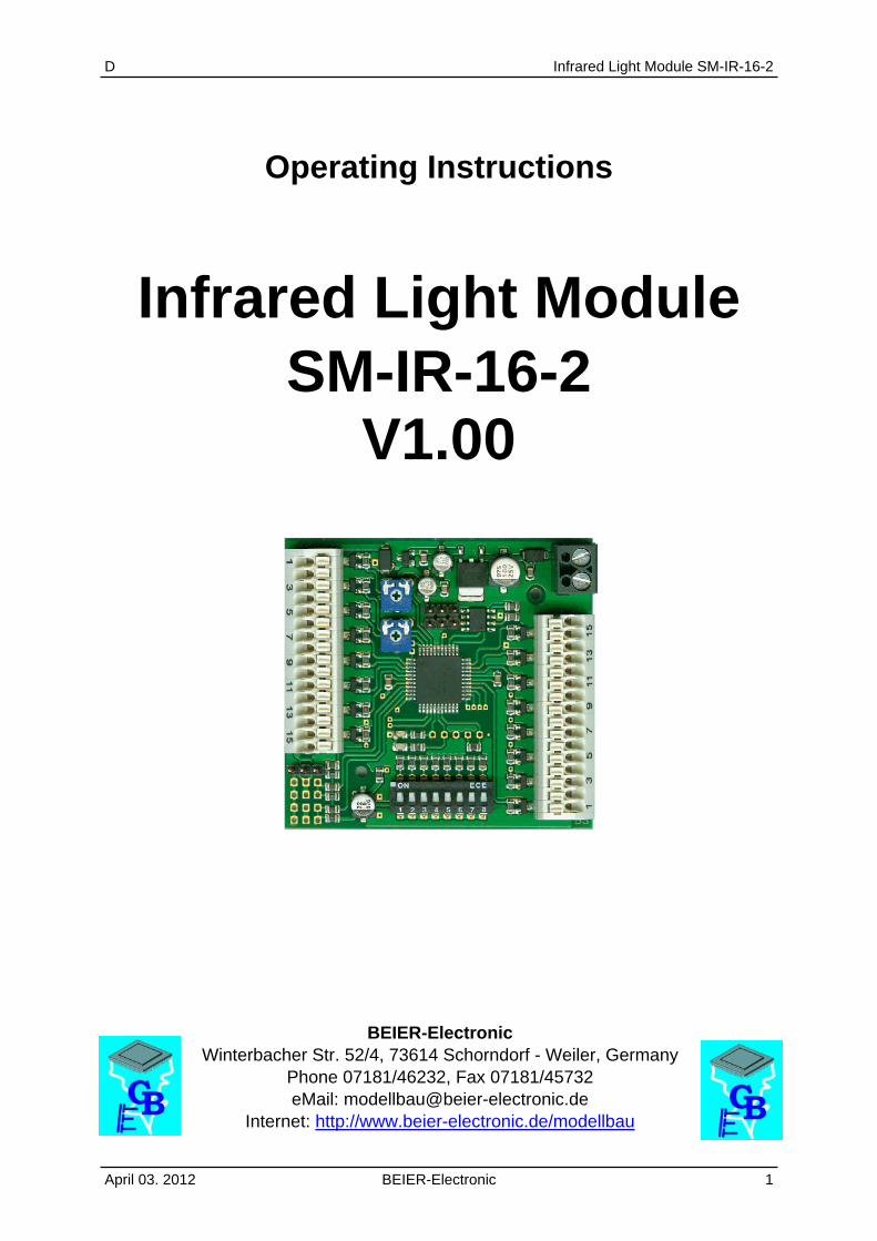
Operating Instructions
Infrared Light Module SM-IR-16-2
V1.00
BEIER-Electronic Winterbacher Str. 52/4, 73614 Schorndorf - Weiler, Germany
Phone 07181/46232, Fax 07181/45732 eMail: [email protected]
Internet: http://www.beier-electronic.de/modellbau

D Infrared Light Module SM-IR-16-2
2 BEIER-Electronic April 03. 2012
Table of contents
Table of contents ........................................................................................................ 2
Description.................................................................................................................. 3
Safety advisory ........................................................................................................... 3
Technical data ............................................................................................................ 4
DIP Switch S1............................................................................................................. 4
Terminal assignment .................................................................................................. 5
Wiring diagram ........................................................................................................... 6
Supply voltage connection.......................................................................................... 6
Connecting lamps/LEDs to the switch outputs............................................................ 7
Connecting the servos................................................................................................ 8
Connecting IR diode and IR receiver.......................................................................... 9
Outputs 1-12............................................................................................................. 10
Outputs 13-16........................................................................................................... 10
Activation of 4 specialized light functions.................................................................. 12
Controlling the servos............................................................................................... 12

D Infrared Light Module SM-IR-16-2
April 03. 2012 BEIER-Electronic 3
Description
The Infrared Light Module SM-IR-16-2 is an expansion module to our Sound Module USM-RC-2. This module can be used to e.g. control the lights of a truck trailer. An infrared diode transmits the light signals wirelessly. Thus, a cable from the towing vehicle to the trailer is not necessary. However, the trailer does require a separate battery. Besides being used for trailer lighting, there are many other application possibilities for the light module. The SM-IR-16-2 has 16 switch outputs for e.g. lamps and LEDs. 12 of the 16 outputs are a copy of the 12 switch outputs of the USM-RC-2. There are different functions for the other 4 outputs such as 1- and 4-channel all-round light, 4/8-channel chaser light and different flashers. In addition to the 16 switch outputs there are also 2 servo outputs, which control different movements. These may be used for trailer supports, locking and unlocking of a seat post, controlling the tipping movement of a dump truck and many other applications. The speed of the all-round light, chaser light and flasher can be configured with a trimmer.
Safety advisory
Read these operating instructions carefully before activation and keep them on hand for future usage!
The integrated circuits on the light module are sensitive to electrostatic charges. You must “discharge” yourself (e.g. by touching a heater or another grounded device) before touching any component.
The light module should be installed in a proper casing to ensure fail-safe operation.
The light module should only be operated with the supply voltage specified in the technical data.
Wiring work may only be conducted in a non-energized state. Children under the age of 14 are not permitted to operate the light module.
D Infrared Light Module SM-IR-16-2
4 BEIER-Electronic April 03. 2012
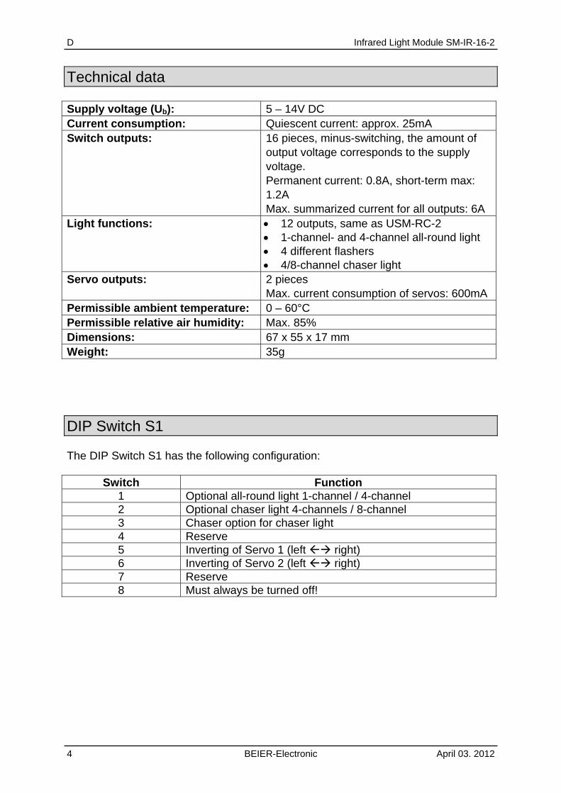
Technical data
Supply voltage (Ub): 5 – 14V DC Current consumption: Quiescent current: approx. 25mA Switch outputs: 16 pieces, minus-switching, the amount of
output voltage corresponds to the supply voltage. Permanent current: 0.8A, short-term max: 1.2A Max. summarized current for all outputs: 6A
Light functions: 12 outputs, same as USM-RC-2 1-channel- and 4-channel all-round light 4 different flashers 4/8-channel chaser light
Servo outputs: 2 pieces Max. current consumption of servos: 600mA
Permissible ambient temperature: 0 – 60°C Permissible relative air humidity: Max. 85% Dimensions: 67 x 55 x 17 mm Weight: 35g
DIP Switch S1 The DIP Switch S1 has the following configuration:
Switch Function 1 Optional all-round light 1-channel / 4-channel 2 Optional chaser light 4-channels / 8-channel 3 Chaser option for chaser light 4 Reserve 5 Inverting of Servo 1 (left right) 6 Inverting of Servo 2 (left right) 7 Reserve 8 Must always be turned off!
D Infrared Light Module SM-IR-16-2
April 03. 2012 BEIER-Electronic 5
+5 - 14V
0V
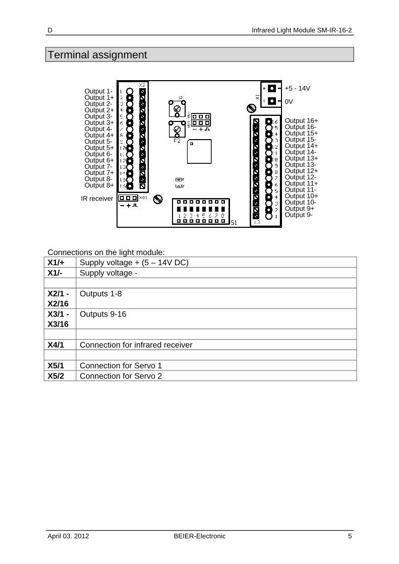
Output 16+Output 16-Output 15+Output 15-Output 14+Output 14-Output 13+Output 13-Output 12+Output 12-Output 11+Output 11-Output 10+Output 10-Output 9+Output 9-
Output 1-Output 1+Output 2-Output 2+Output 3-Output 3+Output 4-Output 4+Output 5-Output 5+Output 6-Output 6+Output 7-Output 7+Output 8-Output 8+
IR receiver X4/1
Terminal assignment Connections on the light module: X1/+ Supply voltage + (5 – 14V DC) X1/- Supply voltage - X2/1 - X2/16
Outputs 1-8
X3/1 - X3/16
Outputs 9-16
X4/1 Connection for infrared receiver X5/1 Connection for Servo 1 X5/2 Connection for Servo 2

D Infrared Light Module SM-IR-16-2
6 BEIER-Electronic April 03. 2012
Wiring diagram
All wiring work must be conducted while power supply is turned off!
Supply voltage connection Connect a power supply of DC 5 – 14V (e.g. a battery) to Terminal X1. Please make sure the polarities are connected correctly!
D Infrared Light Module SM-IR-16-2
April 03. 2012 BEIER-Electronic 7
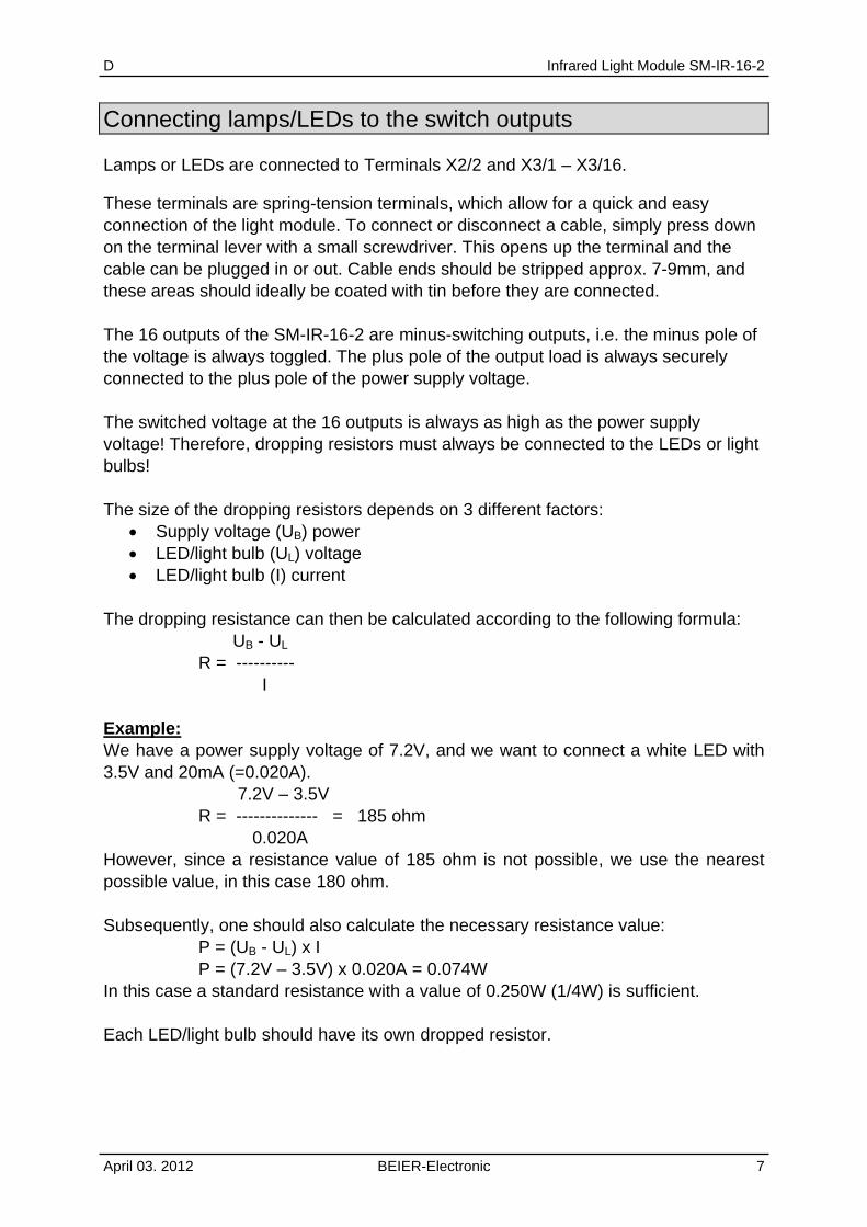
Connecting lamps/LEDs to the switch outputs Lamps or LEDs are connected to Terminals X2/2 and X3/1 – X3/16.
These terminals are spring-tension terminals, which allow for a quick and easy connection of the light module. To connect or disconnect a cable, simply press down on the terminal lever with a small screwdriver. This opens up the terminal and the cable can be plugged in or out. Cable ends should be stripped approx. 7-9mm, and these areas should ideally be coated with tin before they are connected. The 16 outputs of the SM-IR-16-2 are minus-switching outputs, i.e. the minus pole of the voltage is always toggled. The plus pole of the output load is always securely connected to the plus pole of the power supply voltage. The switched voltage at the 16 outputs is always as high as the power supply voltage! Therefore, dropping resistors must always be connected to the LEDs or light bulbs! The size of the dropping resistors depends on 3 different factors:
Supply voltage (UB) power LED/light bulb (UL) voltage LED/light bulb (I) current
The dropping resistance can then be calculated according to the following formula: UB - UL R = ---------- I Example: We have a power supply voltage of 7.2V, and we want to connect a white LED with 3.5V and 20mA (=0.020A). 7.2V – 3.5V R = -------------- = 185 ohm 0.020A However, since a resistance value of 185 ohm is not possible, we use the nearest possible value, in this case 180 ohm. Subsequently, one should also calculate the necessary resistance value: P = (UB - UL) x I P = (7.2V – 3.5V) x 0.020A = 0.074W In this case a standard resistance with a value of 0.250W (1/4W) is sufficient. Each LED/light bulb should have its own dropped resistor.

D Infrared Light Module SM-IR-16-2
Connecting the servos 2 servos can be connected to pin strips X5/1 and X5/2. Attention: The maximum current consumption of the servos may not exceed 600mA! Before connecting, please check the technical data of your servos. If you want to use servos with higher current consumption, the servo cannot be supplied via the plug-in on the light module! The red cable of the servos must be directly supplied with a voltage of 4-6V. See example of circuit diagram:
8 BEIER-Electronic April 03. 2012
D Infrared Light Module SM-IR-16-2
April 03. 2012 BEIER-Electronic 9
Connecting IR diode and IR receiver IR transmission: The Sound Module USM-RC-2 is required for the proper functioning of the Light Module SM-IR-16-2! Operation with other sound modules/regulators is not possible. The IR transmission must be activated in the USM-RC-2 Sound-Teacher (Configuration General). In order to ensure a secure connection the distance between IR diode and IR receiver should not be greater than 10cm. If the IR transmission is working properly, the red LED on the light module will blink at a cyclical interval. If the light module does not receive any IR signals for more than 2 s, all outputs are turned off. Connecting the IR diode: The included IR diode is delivered with a soldered-on cable and a 3-pole plug-in. The black plug-in is connected to pin strip X9 on Sound Module USM-RC-2. The brown cable points to the SD card, the orange cable in the direction of the grey terminal strip X1. Connecting the IR receiver: The IR receiver is delivered with a soldered-on cable and a 3-pole plug-in. The black plug-in is connected to pin strip X4/1 on the sound module. The brown cable points to the edgeboard, the orange cable to the inner plate. The half-round dome is the sensitive side of the receiver. The IR diode should point to it.
D Infrared Light Module SM-IR-16-2
10 BEIER-Electronic April 03. 2012
Outputs 1-12 Outputs 1-12 are a copy of the 12 outputs of the USM-RC-2. This means that every time an output switches on the USM-RC-2, the output on the SM-IR-16-2 also switches. Example: Output 10 on the sound module is configured as “Blinker right”. When the blinker is activated on the right, Output 10 on the sound module (blinker for towing vehicle) and also Output 10 on the light module (blinker for trailer) will blink.
!!! CAUTION !!! The 16 switch outputs are not short-circuit-proof!
A short circuit or an overload will destroy the outputs! Destroyed outputs are not covered by warranty since they have clearly been
caused by improper connection.
Outputs 13-16 The 4 outputs 13-16 have different specialized light functions:
All-round light (1x4-channel or 4x1-channel) Blinker/flasher Chaser light (4-channel or 8-channel)
The specialized light functions are clearly assigned to these outputs and cannot be configured to other outputs. There are other options for the all-round light and the chaser light, which can be configured via DIP Switch S1.1 – S1.3. The speed of specialized light functions can be adjusted with trimmer P1. 1-channel all-round light (4 pieces) The 1-channel all-round light with one output simulates a rotating all-round light. Of course, the light does not actually turn; the effect is created by a constant increase and decrease of brightness. From a distance the light appears to be rotating. There are a total of 4 pieces for the 1-channel all-round light. The speeds of the 4 all-round lights are purposefully set at different speeds. They are not synchronized. The speed of the 1-channel all-round lights can be adjusted with trimmer P1.

D Infrared Light Module SM-IR-16-2
April 03. 2012 BEIER-Electronic 11
4-channel all-round light (1 piece) The 4-channel all-round light is an improved version of the 1-channel all-round light. The all-round light with 4 outputs simulates a rotating all-round light. The 4 connected lamps/LEDs of the 4-channel all-round light also do not actually rotate; the effect is once again created by increasing and decreasing the brightness of the 4 outputs. The speed of the 1-channel all-round light can be adjusted with trimmer P1. Flasher/blinker (4 pieces) If the flashers/blinkers are activated, outputs 13-16 will flash at different rhythms. These 4 outputs are always activated at the same time. The different flash-/blink options let you choose the desired output. A combination of several outputs can create interesting effects (e.g. modern flashing police lights with 3 LEDs at outputs 13, 14 and 15). Output 13: Short flash impulse Output 14: Short double light impulse Output 15: Short double light impulse, chronologically offset to Output 14. Output 16: Blinker The speed of the flasher/blinker can be adjusted with trimmer P1. Chaser light (4-channel or 8-channel) A 4-channel chaser light can be created via the 4 outputs 13-16. Outputs 9 - 12 are also used for the 8-channel chaser light. These outputs cannot be actuated from the sound module. The DIP Switch S1.2 determines the type of chaser light: DIP Switch S1.2 off 4-channel chaser light (Outputs 13 – 16) DIP Switch S1.2 on 8-channel chaser light (Outputs 9 – 16) 2 different operating options can be selected via DIP switch 3: DIP Switch S1.3 off Chaser light only runs in one direction. DIP Switch S1.3 on Chaser light runs back and forth. The speed of the chaser light can be adjusted with trimmer P1.

D Infrared Light Module SM-IR-16-2
12 BEIER-Electronic April 03. 2012
Activation of 4 specialized light functions The 4 specialized light functions can be activated via the free function configuration in USM-RC-2 Sound-Teacher, via the proportional channels, the nautic mode, the EKMFA mode or the switch inputs. In Sound-Teacher the functions are called:
IR: Rotation beacon IR: Flasher IR: Chaser light
Controlling the servos 2 servos can be connected to the light module. The two servos can be controlled separately. The rotational direction of the two servos can be inverted via DIP Switch S1.5 (Servo 1) and S1.6 (Servo 2). In Sound-Teacher a basic position and 2 further positions can be set for each servo, which can then “run”. The speed can also be adjusted in Sound-Teacher. The programmed positions can be activated via the free function configuration in USM-RC-2 Sound-Teacher, via the proportional channels, the nautic mode, the EKMFA mode or the switch inputs. In Sound-Teacher the functions are called:
IR: Servo 1 Position 1 IR: Servo 1 Position 2 IR: Servo 2 Position 1 IR: Servo 2 Position 2
For more detailed information on the servo functions please read the operating instructions for the USM-RC-2.