Informed structures: forensic information modelling structures: forensic ... Forensic engineering is...
8
Informed structures: forensic information modelling & 1 Elisabeth A. Malsch PhD, PE Vice President, Thornton Tomasetti, New York, USA & 2 Francesca Brando PhD Project Director, Thornton Tomasetti, New York, USA & 3 Gary F. Panariello PhD, PE, SE Managing Principal, Thornton Tomasetti, New York, USA 1 2 3 Forensic information modelling is an extension of building information modelling. Forensic information modelling is an approach for collecting, sorting and explaining forensic information about structures. Careful and consistent nomenclature and tagging is the backbone of any large-scale investigation. Every photo, reference document, maintenance record or material test is related to a physical object. Forensic information models codify the relationship between the data and the physical structure in an interactive three-dimensional environment. This aids in understanding the global behaviour of the structure and in identifying changes in behaviour over time. In addition, forensic information modelling has been essential for explaining engineering findings and repair options to the wider public. 1. Introduction Forensic engineering is primarily the practice of understanding existing structures that have behaved in an unexpected or unplanned way. Engineering does not stop when a building or structure is opened to the public. The ongoing investigation and maintenance of the built world is a significant responsi- bility shared by public and private institutions, and a great and often immediate concern to the public at large. Determining the cause of a structural defect or collapse requires an in-depth knowledge of the in situ behaviour of the structure over time. For example, before a structure collapses, it is in equilibrium. Something has to change either in the loading or in the capacity of the structure to cause it to fall down. Under- standing the original design, the original construction and the maintenance history of any structure is essential to determin- ing its condition and identifying which elements may have changed. 2. Forensic information modelling Forensic information modelling is analogous to more ubiqui- tous map mash-ups. Using Google maps, Bing, Leaflet or other modern mapping platforms, it is possible to create overlays and tag items. Meteorologists have used this kind of map for a long time (National Oceanic and Atmospheric Administration (NOAA)). This is especially useful for present- ing timely information about storms (see www.google.org/ crisisresponse/). Analogously, the goal of a forensic informa- tion model is to collect and display pertinent or timely information about a structure. A forensic information model consists of two basic parts: (a)a table of information and (b) a model of the structure, see Figure 1. For simple projects a spreadsheet is sufficient. Building information modelling programs such as Revit allow additional properties to be added for each modelled element. These additional properties correspond to columns on the spreadsheet. The properties can include analysis results, inspection results or links to other documents. The real power of the forensic information model is the ability to highlight members of interest and to communicate the extent of damage (Brando et al., 2013). As building information models become more prevalent the forensic information model approach will become more important. Architects, engineers and contractors are using building information models to communicate their designs, identify conflicts, estimate costs and punch-list issues. Building owners who use building information models for facility Forensic Engineering Volume 168 Issue FE1 Informed structures: forensic information modelling Malsch, Brando and Panariello Proceedings of the Institution of Civil Engineers Forensic Engineering 168 February 2015 Issue FE1 Pages 9–16 http://dx.doi.org/10.1680/feng.14.00006 Paper 1400006 Received 23/05/2014 Accepted 09/09/2014 Keywords: information technology/maintenance & inspection/research & development ice | proceedings ICE Publishing: All rights reserved 9
Transcript of Informed structures: forensic information modelling structures: forensic ... Forensic engineering is...
Informed structures: forensicinformation modelling
&1 Elisabeth A. Malsch PhD, PEVice President, Thornton Tomasetti, New York, USA
&2 Francesca Brando PhDProject Director, Thornton Tomasetti, New York, USA
&3 Gary F. Panariello PhD, PE, SEManaging Principal, Thornton Tomasetti, New York, USA
1 2 3
Forensic information modelling is an extension of building information modelling. Forensic information modelling is
an approach for collecting, sorting and explaining forensic information about structures. Careful and consistent
nomenclature and tagging is the backbone of any large-scale investigation. Every photo, reference document,
maintenance record or material test is related to a physical object. Forensic information models codify the relationship
between the data and the physical structure in an interactive three-dimensional environment. This aids in
understanding the global behaviour of the structure and in identifying changes in behaviour over time. In addition,
forensic information modelling has been essential for explaining engineering findings and repair options to the wider
public.
1. Introduction
Forensic engineering is primarily the practice of understanding
existing structures that have behaved in an unexpected or
unplanned way. Engineering does not stop when a building or
structure is opened to the public. The ongoing investigation
and maintenance of the built world is a significant responsi-
bility shared by public and private institutions, and a great and
often immediate concern to the public at large. Determining
the cause of a structural defect or collapse requires an in-depth
knowledge of the in situ behaviour of the structure over time.
For example, before a structure collapses, it is in equilibrium.
Something has to change either in the loading or in the
capacity of the structure to cause it to fall down. Under-
standing the original design, the original construction and the
maintenance history of any structure is essential to determin-
ing its condition and identifying which elements may have
changed.
2. Forensic information modelling
Forensic information modelling is analogous to more ubiqui-
tous map mash-ups. Using Google maps, Bing, Leaflet or
other modern mapping platforms, it is possible to create
overlays and tag items. Meteorologists have used this kind of
map for a long time (National Oceanic and Atmospheric
Administration (NOAA)). This is especially useful for present-
ing timely information about storms (see www.google.org/
crisisresponse/). Analogously, the goal of a forensic informa-
tion model is to collect and display pertinent or timely
information about a structure.
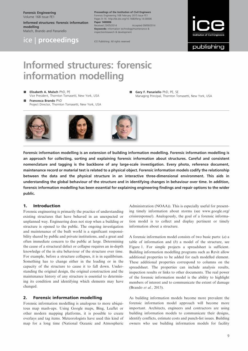
A forensic information model consists of two basic parts: (a) a
table of information and (b) a model of the structure, see
Figure 1. For simple projects a spreadsheet is sufficient.
Building information modelling programs such as Revit allow
additional properties to be added for each modelled element.
These additional properties correspond to columns on the
spreadsheet. The properties can include analysis results,
inspection results or links to other documents. The real power
of the forensic information model is the ability to highlight
members of interest and to communicate the extent of damage
(Brando et al., 2013).
As building information models become more prevalent the
forensic information model approach will become more
important. Architects, engineers and contractors are using
building information models to communicate their designs,
identify conflicts, estimate costs and punch-list issues. Building
owners who use building information models for facility
Forensic EngineeringVolume 168 Issue FE1
Informed structures: forensic informationmodellingMalsch, Brando and Panariello
Proceedings of the Institution of Civil Engineers
Forensic Engineering 168 February 2015 Issue FE1
Pages 9–16 http://dx.doi.org/10.1680/feng.14.00006
Paper 1400006
Received 23/05/2014 Accepted 09/09/2014
Keywords: information technology/maintenance &
inspection/research & development
ice | proceedings ICE Publishing: All rights reserved
9
MPinzuti
Typewritten Text
Courtesy Forensic Engineering, http://www.icevirtuallibrary.com/content/issue/feng/168/1
Offprint provided courtesy of www.icevirtuallibrary.com Author copy for personal use, not for distribution
management will have added a large amount of information
about the mechanical equipment and tenant structural
changes, for example. This wealth of information will form
the basis for future forensic investigations. The basis of every
building information model is the same as for a forensic
information model: (a) a table of information and (b) a model
of the structure.
The conventional map applications can rely on standardised
coordinate systems, latitude, longitude, global positioning
system (GPS) and so on. There are no standard coordinate
systems yet for building applications (see www.opengeospatial.
org). The most challenging aspect of forensic information
modelling is anticipating the different kinds of information
that will need to be captured and displayed in the model. If the
resolution of the model is too small, the data management task
becomes extremely time-consuming. However, adding infor-
mation to each sub-member may show a pattern that informs
the analysis better than a lower resolution approach.
A second challenging aspect of a forensic information model is
to keep it updateable and relevant over time. Consequently,
another fundamental component of forensic information
modelling is interoperability. The tables of information can
be re-sorted according to new naming conventions using a
database; the models themselves can be translated between
different programs.
An added benefit of interoperability is that analysis models,
geometrical models and the associated information can be
combined as needed to show the relevant information about a
structure. For investigations the information may include an
animation of how the damage to the structure occurred. The
assumptions required to perform the failure progression analysis
and produce the animation can be embedded in the model.
3. ProjectsSince forensic information modelling was first conceived in
2008, the method of collecting, sorting and sharing informa-
tion has been applied to a number of different kinds of
investigations (Cho, 2008). The applications have ranged from
routine inspections to emergency retrofit and collapse investi-
gations. Three case studies will be discussed.
3.1 Case 1: I-35W Bridge collapse investigation
Forensic information modelling was developed for the I-35W
Bridge collapse investigation (Malsch et al., 2011). Access to the
bridge wreckage was not granted to non-government engineers
until almost a year after the collapse. However, access to the
drawings, shop drawings, inspection documentation and reports
developed about the I-35W Bridge over the years was provided.
The resulting holistic approach to the collapse investigation
shifted the focus from the under-designed and failed gusset
plates to the larger question of why the bridge collapsed on 1
August 2007 at 6?04 p.m. and how to explain the cause to the
victims of the collapse and the public at large. The collapse
initiated due to temperature loads that had been increasing over
the many years that the bridge had been in service. Contrary to
the conventional wisdom, the undersized gusset plates were not
the cause of the collapse (Malsch et al., 2012).
3.1.1 Forensic information model for investigation
For the forensic information model for the I-35W Bridge
investigation, information was collected in spreadsheets; the
Tag After Before Unk. IMG. Doc.U1-U2 x 2 a21U2-U3 x 23 a55U3-U4 x 254 a453U4-U5 x 300 a22U5-U6 x 301 a45
Damage data
(a)
Properties
Damage after: □Damage before: □Unknown cause: □
Image: img254.jpgReport: a453.doc
(b)
Tag: U3-U4
Figure 1. (a) Table of information; (b) model of the structure
Forensic EngineeringVolume 168 Issue FE1
Informed structures: forensicinformation modellingMalsch, Brando and Panariello
10

Offprint provided courtesy of www.icevirtuallibrary.com Author copy for personal use, not for distribution
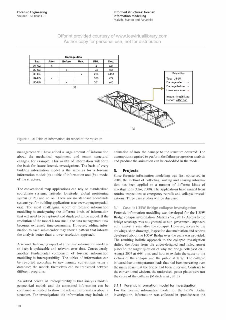
bridge geometry was built in a SAP model (Finite Element
Analysis software development by Computer and Structures
International). The SAP model was further converted to Revit
and the spreadsheets were loaded into Revit’s database
(Figure 2). Revit’s building information modelling capabilities
were employed to filter the information and to display the photo
and document data associated with each element. The Revit
model was then combined with a non-linear LS-Dyna analysis
and rendered in Studio Max to show the progression of the
collapse (Cao et al., 2013).
For the I-35W Bridge the naming of the members was well
defined. The original drawings labelled each panel point and
connection. The inspection documents and recovery informa-
tion followed this naming convention. The Revit model
database listed each member and each connection in the
superstructure. The SAP model elements were given the same
labels and SAP’s built-in spreadsheet capability was used to
transfer the information to Revit.
Every defect mentioned in every inspection report was logged
for each member and each connection referenced. Any photos
given in the inspection reports were similarly related to the to
which member they pertained. In practice this means populat-
ing a table. The first column is the member or connection
name. The second column is the type of information, in this
case ‘inspection report’ or ‘photo’. The third column is the
year. The fourth column is the information contained in the
report. The fifth column contains the investigators’ comments
– including a description of the photo. The sixth column
contains a link to the original report or photo location. It was
unclear at the beginning of the investigation what factors
would be important so the text of the, often hand-written,
inspection reports were transcribed verbatim.
(a)
(b)
Figure 2. I-35W Bridge: (a) forensic information model; (b) collapse
rendering
Forensic EngineeringVolume 168 Issue FE1
Informed structures: forensicinformation modellingMalsch, Brando and Panariello
11
Offprint provided courtesy of www.icevirtuallibrary.com Author copy for personal use, not for distribution
This process was repeated with the information collected about
the collapsed bridge. Every plastic hinge or fracture identified
in every member or connection was logged in a similar
spreadsheet. In addition, material information from original
coupon tests and post-collapse testing was logged on an
element-by-element basis.
The loaded forensic information model – with the inspection,
recovery and stress information – was used to evaluate which
elements were critical. Detailed substructure models for two
gusset plates and a top and bottom chord were analysed using
Abaqus. The material information was input from the initial
coupon tests and post-collapse investigations. The results of
the substructure model along with the linear static analysis
were used to perform a non-linear collapse analysis in LS-
Dyna. A full description of the LS-Dyna model is available in
the reference (Cao et al., 2013).
Home-made translators were used to convert the text-based LS-
Dyna output back into Revit. Commercially available transla-
tors were used to create the Studio Max model from the Revit
model. The commercially available translators were modified so
that the forensic information attached to the elements in the
Revit model was included in the Studio Max model.
Cross-referencing the multi-year inspection history at the bridge
member locations revealed that the area under the expansion
joints, including the roller bearings, had been corroding and
collecting debris for many years. Further, addition of loads,
strength and stress analysis to the model showed that the gusset
plate loading changed most significantly decades earlier during a
separate retrofit operation. This helped show why the underside
gusset plates did not tell the whole story. Plotting the plastic
hinges and other damage on the bridge along with the video and
other recovery information helped to focus the investigation on
the south end of the bridge in the panel point around the
undersized gusset plate. The stress analysis results due to
temperature loading helped to focus the investigation on the
bottom chord. Buckling of the bottom chord was determined to
be the initiating failure causing the I-35W Bridge collapse.
3.2 Case 2: Sherman Minton Bridge emergency
bridge closure and retrofit
Cracks were discovered on the main tie of the Sherman Minton
Bridge and the bridge was shut down. Retrofit options were
developed as quickly as possible. The design drawings, shop
drawings and inspection history were collected in a forensic
information model and shared with the whole design team and
the public officials responsible for the bridge. The impact of
the retrofit on the tie and the larger bridge structure was
considered. The retrofit options were shared with the public at
large. The bridge was repaired, retrofitted and reopened before
the Kentucky Derby.
3.2.1 Forensic information model for retrofit
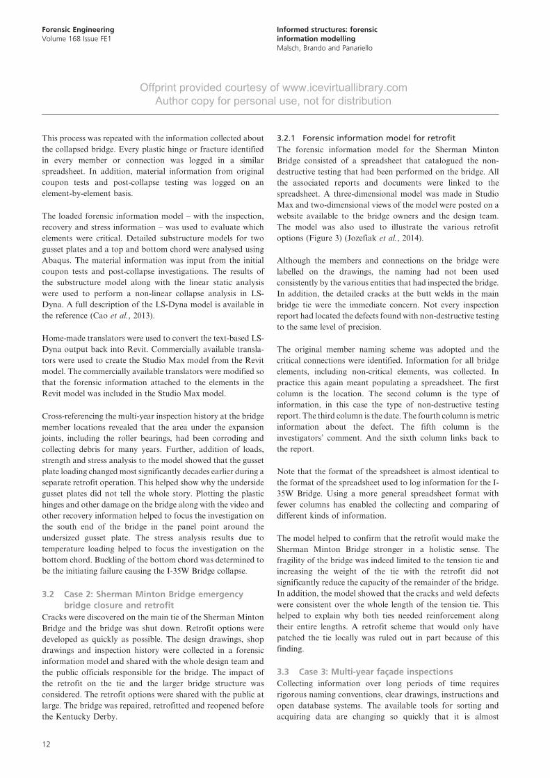
The forensic information model for the Sherman Minton
Bridge consisted of a spreadsheet that catalogued the non-
destructive testing that had been performed on the bridge. All
the associated reports and documents were linked to the
spreadsheet. A three-dimensional model was made in Studio
Max and two-dimensional views of the model were posted on a
website available to the bridge owners and the design team.
The model was also used to illustrate the various retrofit
options (Figure 3) (Jozefiak et al., 2014).
Although the members and connections on the bridge were
labelled on the drawings, the naming had not been used
consistently by the various entities that had inspected the bridge.
In addition, the detailed cracks at the butt welds in the main
bridge tie were the immediate concern. Not every inspection
report had located the defects found with non-destructive testing
to the same level of precision.
The original member naming scheme was adopted and the
critical connections were identified. Information for all bridge
elements, including non-critical elements, was collected. In
practice this again meant populating a spreadsheet. The first
column is the location. The second column is the type of
information, in this case the type of non-destructive testing
report. The third column is the date. The fourth column is metric
information about the defect. The fifth column is the
investigators’ comment. And the sixth column links back to
the report.
Note that the format of the spreadsheet is almost identical to
the format of the spreadsheet used to log information for the I-
35W Bridge. Using a more general spreadsheet format with
fewer columns has enabled the collecting and comparing of
different kinds of information.
The model helped to confirm that the retrofit would make the
Sherman Minton Bridge stronger in a holistic sense. The
fragility of the bridge was indeed limited to the tension tie and
increasing the weight of the tie with the retrofit did not
significantly reduce the capacity of the remainder of the bridge.
In addition, the model showed that the cracks and weld defects
were consistent over the whole length of the tension tie. This
helped to explain why both ties needed reinforcement along
their entire lengths. A retrofit scheme that would only have
patched the tie locally was ruled out in part because of this
finding.
3.3 Case 3: Multi-year facade inspections
Collecting information over long periods of time requires
rigorous naming conventions, clear drawings, instructions and
open database systems. The available tools for sorting and
acquiring data are changing so quickly that it is almost
Forensic EngineeringVolume 168 Issue FE1
Informed structures: forensicinformation modellingMalsch, Brando and Panariello
12

Offprint provided courtesy of www.icevirtuallibrary.com Author copy for personal use, not for distribution
impossible to set a standard that is not immediately out of
date. The basis of any forensic information model is a model
with uniquely labelled members, and a spreadsheet of
information that correlates to the model (Figure 4). By keeping
the support documents as simple as possible, historical
information and new information can be captured and
presented together (Karanci and Nagata, 2012).
A challenge for multi-year inspections in particular is keeping
the model up to date. As technology changes, the process of
(c)
(b)(a)
Topchord
TieColumns
Bottomchord
Verticals Diagonals
Top laterals
Sway frames
Figure 3. Sherman Minton Bridge: (a) three-dimensional model of
the structure; (b) table of information; (c) webshare
Forensic EngineeringVolume 168 Issue FE1
Informed structures: forensicinformation modellingMalsch, Brando and Panariello
13

Offprint provided courtesy of www.icevirtuallibrary.com Author copy for personal use, not for distribution
Panels with newlydocumented issues
Panels with previouslydocumented issues
Panels with issuesmentioned in a separatereport
Panels with newlydocumented issues
NORTH 1-3
North
520 Madison
6 10
20Thornton Tomasetti
N
Matchline
Madison Ave 54th street
Matchline
25
24
23
22
21
26
987
Panels with previouslydocumented issues
Panels with issuesmentioned in a separate report
Figure 4. 520 Madison facade forensic information model:
(a) north elevation overview image; (b) detailed view between
column lines 6 and 10 and floors 20 and 26 with a damage key;
(c) detailed information for one panel
Forensic EngineeringVolume 168 Issue FE1
Informed structures: forensicinformation modellingMalsch, Brando and Panariello
14

Offprint provided courtesy of www.icevirtuallibrary.com Author copy for personal use, not for distribution
adding and updating information becomes more automated.
Many forensic engineers and architects are using tablet
computers to input inspection information directly into the
model (TPAS, Newforma, Autocad 360). This not only saves
time on report production but also presents the prior
inspection information to the engineer or architect in the field.
Still, the computer software is not yet seamless and a piece of
paper has the advantage that it does not crash or run out of
power; it can even be used in a light drizzle.
In addition, as building owners implement their own information
databases, perhaps associated with the original building informa-
tion model, the approach adopted by forensic engineers to
translating and inputting information has to remain flexible.
Proprietary systems can sometimes be more of a hindrance than a
help. Some need proprietary translators to access and mine the
information. The investigator has to click through each item in the
system and transcribe the information contained in it. On the other
hand, systems that output flat spreadsheet or text files are easier to
use in forensic investigations. Flat spreadsheets or texts can more
easily be converted into the format needed for the given analysis.
On a facade inspection project that spans many years, the biggest
challenge is choosing what level of resolution is important. For
repair procedures, only the general categories of crack and panel
location are important. On multi-year inspections, the quantity
of detailed forensic information about specific crack sizes,
lengths and locations can overshadow the repair information.
The forensic information model of the building whose cladding
was being inspected showed whether or not any specific panel
had an issue or had been repaired. The detailed crack
information is kept in the backup documentation. This helps
to discern whether the same locations were being repaired again
and again over the years or whether, instead, new issues were
appearing. This in turn is used to inform the building owner
about critical locations and allows the architect, engineer and
contractor to improve the repairs approach and implementation.
Each panel on the building was labelled by column line and floor
according to the original drawings. Sub panels were numbered left
to right within the column line and floor locations. Additional
crack location detail was captured with sketches. The same general
spreadsheet form used for the I-35W Bridge investigation and the
Sherman Minton retrofit was used. The first column is the panel or
sub-panel name. The second column is the type of data captured.
The third column is the date. The fourth column is the short
damage description from a list of preset descriptions. The fifth
column is the investigators’ comment. The sixth column is a link to
a scan of the field report, photo or other relevant media.
4. Lessons learnedAs understanding, tools and technology have progressed, the
basic purpose of the forensic information model has stayed
the same. The purpose of the model is to convey information.
For the I-35W Bridge collapse the model helped push
investigation beyond the obvious flaw in the gusset plate.
For the Sherman Minton Bridge it helped the team come to a
consensus about the immediate urgency of the bridge’s
condition and helped to communicate the retrofit solution.
For multi-year inspections the most important functions of
the model are to identify areas that need immediate attention
and communicate that those items have been addressed
adequately. These are the same kinds of information that
forensic engineers have had to communicate in person, with
memos, drawings and sketches.
The challenge for forensic information models is to assist in the
process of collecting and communicating information without
making the process more difficult or overshadowing the purpose
of the investigation. From the I-35W Bridge it can be firmly
concluded that no quantity of drawings, photos, documentation,
or even a laser scan, can replace physical access to a collapsed or
damaged structure. The Sherman Minton Bridge collapse edifies
that online communication cannot supplant face-to-face meetings.
The entire design team, government officials, contractors and
inspectors met together in person over the span of the bridge
assessment and retrofit. Similarly, for multi-year inspections, a
forensic information model does not supplant ongoing dialogue
with the structure’s owner and maintenance team.
4.1 The future
This simple approach to forensic data, a model with uniquely
labelled members and an associated spreadsheet, allows the
forensic information model to be incredibly extensible. The
spreadsheet information can be updated with forms loaded
onto tablet computers. The data can be displayed in real
time on three-dimensional models shared by many people
using different platforms: GTeam (see www.gteam.com/),
Autocad360 (see www.autocad360.com/) and Bimserver (see
www.bimserver.org/).
The amount of information available to building owners and
forensic engineers is increasing. Accelerometers are becoming
less expensive and thus ubiquitous. Laser scanners and similar
hand-held measuring devices are enabling the collection of
millions of points of data. The challenge is to discern the signal
from the noise.
5. ConclusionThe changes in how buildings are designed and how structural
information is conveyed are changing how forensic engineers
understand and explain their structures and their findings.
Three-dimensional models are easier for the layperson to
understand than two-dimensional drawings. Three-dimensional
models are easier still. Forensic information modelling assists in
understanding the as-built information of a structure. This in
Forensic EngineeringVolume 168 Issue FE1
Informed structures: forensicinformation modellingMalsch, Brando and Panariello
15

Offprint provided courtesy of www.icevirtuallibrary.com Author copy for personal use, not for distribution
turn is crucial to understanding how the structure has behaved
and how it will behave in the future. This new kind of database
may help discern the important information from the increasing
volume of information that is being received about structures.
REFERENCES
Brando F, Iannitelli A, Cao L et al. (2013) Forensic investigation
modeling: a new forensic tool. Journal of Civil Engineering,
ASCE 83(1): 48–53.
Cao L, Malsch EA, Brando F, Panariello GF and Abruzzo J (2013)
Calculating collapse: analytical approaches for investigating
the cause of the I-35 West Bridge failure. Forensic Engineer:
Informing the Future with Lessons from the Past: Proceedings
of the 5th International Conference on Forensic Engineering
(Carpenter J (ed.)). ICE Publishing, London, UK.
Cho A (2008) Building information models are now crossing
over. McGraw-Hill Construction Engineering News-Record,
see http://enr.construction.com/news/transportation/
archives/080618.asp# (accessed 18/06/2008).
Jozefiak S, Lau J, Abruzzo J et al. (2014) Forensic information
modeling in bridge renovation: Sherman Minton Bridge. In
Bridge Maintenance, Safely Management and Life
Exfension (Chen A, Frangopol DM and Ruan X (eds)).
CRS Press, Boca Raton, FL, USA, pp. 1441–1447.
Karanci E and Nagata R (2012) A new method for managing
and presenting facade investigation data. In Forensic
Engineering, 2012: Gateway to a Safer Tomorrow (Dolhon
AM, Drerup MJ, Daz de Len A et al. (eds)). ASCE,
REston VA, USA, pp. 861–870.
Malsch EA, Brando F, Iannitelli A, Abruzzo J and Panariello GF (2011)
The causes of the I-35 West Bridge collapse. Proceedings of the
35th IABSE–52nd IASS Symposium, Hemming Group Ltd,
London, UK, pp. 20–23.
Malsch EA, Brando F, Iannitelli A, Abruzzo J and Panariello GF
(2012) Discussion of ‘Nonlinear Finite-Element Analysis of
Critical Gusset Plates in the I-35W Bridge in Minnesota’ by
Minmao Liao, Taichiro Okazaki, Roberto Ballarini,
Arturo E. Schultz and Theodore V. Galambos, 137(1): 59–
68, http://dx.doi.org/10.061/(ASCE)ST.1943-541X.
0000269. Journal of Structural Engineering, ASCE 138(6):
839–840.
Vumbaca V, Brando F, Pinto M et al. (2014) Forensic
investigation in the internet of things. Proceedings of
IABSE Symposium, Madrid, Spain, paper accepted.
WHAT DO YOU THINK?
To discuss this paper, please email up to 500 words to the
editor at [email protected]. Your contribution will be
forwarded to the author(s) for a reply and, if considered
appropriate by the editorial panel, will be published as
discussion in a future issue of the journal.
Proceedings journals rely entirely on contributions sent in
by civil engineering professionals, academics and stu-
dents. Papers should be 2000–5000 words long (briefing
papers should be 1000–2000 words long), with adequate
illustrations and references. You can submit your paper
online via www.icevirtuallibrary.com/content/journals,
where you will also find detailed author guidelines.
Forensic EngineeringVolume 168 Issue FE1
Informed structures: forensicinformation modellingMalsch, Brando and Panariello
16