Collections Management KE EMu Spatial Technologies Turning information into knowledge.
Upload
truongdiepCategory
view
229download
0
Information Technology Specifications
for
(EMU)
Division of Information Technology (DoIT)
Version 2.0 June 21, 2013
Revision History
June 21, 2013 Version 2.0 - Updated to include basis of design part numbers in Division 270000 and Division 27 section updates to current industry standards and specifications. All sections rewritten. Sketches redrawn.
March 18, 2004 Version 1.0 - First publication of document. All sections
developed.
Acknowledgements
EMU Division of Information Technology expresses its appreciation to the following participants in the development and review of this document:
Division of Information Technology, DoIT
(EMU) Rocky Jenkins, Director, Network and Systems Service Ralph Fitzpatrick, Assistant Director of IT Infrastructure Division of Information Technology (DoIT) 118 Pray Harrold Ypsilanti, MI 48197 Phone: 734.487.3141 Fax: 734.481.9290 http://www.emich.edu/it/
Physical Plant Division (EMU)
Chris Longerbeam, Project Engineer Physical Plant 875 Ann St Ypsilanti, MI 48197-2474 Phone: 734.487.3591 Fax: 734.487.8680 http://www.emich.edu/physplant/
DiClemente Siegel Design Inc.
(DSD)
Nick DiGesu, RCDD, ITPM, Senior Associate, Information Technology DiClemente Siegel Design Inc. 28105 Greenfield Road Southfield, MI 48076-3046 Phone: 248.569.1430 Fax: 248.569.0096 http://www.dsdonline.com
Information Technology Specifications v2.0 DiClemente Siegel Design Inc. Eastern Michigan University DSD Project No. 13-0504.00 Division of Information Technology
INFORMATION TECHNOLOGY SPECIFICATIONS TOC - 1
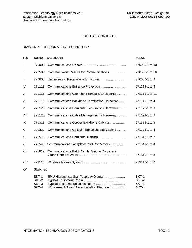
TABLE OF CONTENTS
DIVISION 27 – INFORMATION TECHNOLOGY
Tab Section Description Pages
I 270000 Communications General …………………………………. 270000-1 to 33 II 270500 Common Work Results for Communications ……….….. 270500-1 to 16 III 270600 Underground Raceways & Structures …………….……. 270600-1 to 9 IV 271113 Communications Entrance Protection …………………… 271113-1 to 3 V 271116 Communications Cabinets, Frames & Enclosures …….. 271116-1 to 11 VI 271119 Communications Backbone Termination Hardware …... 271119-1 to 4 VII 271120 Communications Horizontal Termination Hardware …… 271120-1 to 3 VIII 271123 Communications Cable Management & Raceway …….. 271123-1 to 9 IX 271313 Communications Copper Backbone Cabling ……….….. 271313-1 to 6 X 271323 Communications Optical Fiber Backbone Cabling …….. 271323-1 to 8 XI 271513 Communications Horizontal Cabling …………………….. 271513-1 to 7 XII 271543 Communications Faceplates and Connectors ………….. 271543-1 to 4 XIII 271619 Communications Patch Cords, Station Cords, and Cross-Connect Wires……………..……………...…….….. 271619-1 to 3
XIV 273116 Wireless Access System ……………………..…….…….. 273116-1 to 7 XV Sketches
SKT-1 EMU Hierarchical Star Topology Diagram ……………… SKT-1 SKT-2 Typical Equipment Room …………………………………. SKT-2 SKT-3 Typical Telecommunication Room ………………………. SKT-3 SKT-4 Work Area & Patch Panel Labeling Diagram …………… SKT-4

270000 - COMMUNICATIONS GENERAL
Eastern Michigan University DiClemente Siegel Design Inc. Division of Information Technology DSD Project No. 13-0504.00 Information Technology Specifications v2.0
COMMUNICATIONS GENERAL 270000 - 1
SECTION 270000 – COMMUNICATIONS GENERAL
PART 1 - GENERAL
1.1 SUMMARY
A. Eastern Michigan University (EMU) is a comprehensive university founded by the Michigan State Legislature in 1849 and presently the sixth largest university in Michigan with approximately 23,000 students. As with any other university in today’s highly technological world, EMU must move forward in parallel with the telecommunications industry. A sound, structured cabling system is imperative to support voice, data, video, security and other information transport systems in this regard. Therefore, it is the intent of this document to provide specific technical specifications resulting in a standard level of quality throughout the campus. This standardization will involve the review and adoption of existing and emerging industry standards resulting in an efficient telecommunications infrastructure for EMU in the long term.
B. Provide all equipment, materials, labor, and services, not specifically mentioned or shown, which may be necessary to complete or perfect all parts of the installation. Ensure that they are in compliance with requirements stated or reasonably inferred by the contract documents.
1.2 PURPOSE
A. Division 27 Specifications are established to define the standards, criteria, and assumptions to be used to bid, plan, furnish, install, test, and document information transport pathways and systems for Eastern Michigan University (EMU). These Specifications shall form the basis for implementation of the design, installation, inspection, and close-out process.
B. Division 27 is based on NFPA 70 (NEC), National Electrical Safety Code (NESC), Institute of Electronic and Electrical Engineers IEEE, ANSI/TIA/EIA Telecommunication Standards, and BICSI methodologies. The requirements within those documents are not superseded herein unless specifically stated. As required, NEC and NESC code requirements cannot be superseded by this document at any time. ANSI/TIA/EIA standards and BICSI methodologies may be superseded, as specified, or may be made stricter by this document. The absence of a specific reference to an element of these codes, standards, and methodologies does not relieve all parties of compliance with them.
C. Within this document use of the word “shall” marks mandatory requirements. Use of the word “may” or “should” suggests optional elements. All conflicts within this document shall be resolved by EMU Division of Information Technology (DoIT) and/or the Technology Consultant having delegated authority by EMU DoIT. The standards of EMU DoIT shall take precedence in the resolution of any dispute.
D. Where any device or part of equipment is referred to in these specifications in the singular number (e.g., "the switch"), this reference shall be deemed to apply to as many such devices as are required to complete the installation as shown on the Project Drawings.
E. Unauthorized deviations from these Specifications may result in re-design, reconstruction, or re-installation of physical communications elements at the Contractor’s expense. Contractors shall obtain formal written approval prior to bidding and prior to installation in order to deviate from these Specifications or from ANSI/TIA/EIA standards and BICSI methodologies. Contractors shall not deviate from NEC and NESC requirements.
Eastern Michigan University DiClemente Siegel Design Inc. Division of Information Technology DSD Project No. 13-0504.00 Information Technology Specifications v2.0
COMMUNICATIONS GENERAL 270000 - 2
1.3 RELATED DOCUMENTS
A. Not all sections are necessarily issued with each and every project. Project specifications may include a subset of the following sections as required to execute a particular Scope of Work (SOW).
B. Section 270500 – Common Work Results for Communications
C. Section 270600 – Communications Underground Raceways & Structures
D. Section 271100 – Communications Equipment Room
E. Section 271113 – Communications Entrance Protection
F. Section 271116 – Communications Cabinets, Racks, Frames, & Enclosures
G. Section 271119 – Communications Backbone Termination Hardware
H. Section 271120 – Communications Horizontal Termination Hardware
I. Section 271123 – Communications Cable Management & Runway
J. Section 271313 – Communications Copper Backbone Cabling
K. Section 271323 – Communications Optical Fiber Backbone Cabling
L. Section 271513 – Communications Horizontal Cabling
M. Section 271543 – Communications Faceplates and Connectors
N. Section 271619 – Communications Patch Cords, Station Cords, and Cross-Connect Wires
O. Section 273116 – Wireless Access System
1.4 SYSTEM DESCRIPTION
A. Division 27 Specifications address information transport pathways, systems, spaces, media, grounding, identification, testing, and documentation requirements in support of multiple information transport infrastructures.
B. Specific responsibilities of Division 27 include, but are not limited to: 1. Identification of the pathways, cabling, and space requirements necessary to house the
data cabling systems and associated electronic information transport equipment. Pathways and spaces shall be designed and installed to support the known systems and cabling requirements, as well as best effort provisions for those that may be required in the future.
2. Selection and sizing of backbone cabling media, installation, termination, testing, labeling, and documentation methods.
3. Selection and sizing of horizontal cabling media, installation, termination, testing, labeling and, documentation methods.
4. Selection of accessory items such as patch cables and custom cables. 5. Definition and establishment of administration and labeling schemes, conforming to
EMU’s requirements.
Eastern Michigan University DiClemente Siegel Design Inc. Division of Information Technology DSD Project No. 13-0504.00 Information Technology Specifications v2.0
COMMUNICATIONS GENERAL 270000 - 3
6. Securing all necessary permits and licenses, payment of all fees, and provision of all construction work notifications.
7. Compliance with all applicable laws, ordinances, rules, and regulations.
C. It is the intent of these Specifications to provide complete and workable Division 27 communication systems, ready for use by EMU. Any item not specifically called for but normally required for a fully functional system, is to be considered a part of this contract.
1.5 CODES & STANDARDS
A. All work shall be in compliance with the following codes and agencies. Nothing contained within these Specifications shall be misconstrued to permit work not in conformance with the most stringent of applicable codes and standards. It is assumed that bidders have access to, and specific knowledge of, the listed reference materials in order to ensure conformity with them. 1. National Electrical Code (NEC) 2. National Electrical Safety Code (NESC) 3. National Fire Protection Association (NFPA) 4. Federal, State, and Local Codes. 5. National Electronic Manufacturer’s Association (NEMA) 6. Institute of Electronic and Electrical Engineers (IEEE) 7. American National Standards Institute / Electronic Industries Association /
Telecommunication Industries Association (ANSI/EIA/TIA) 8. Occupational Safety & Health Administration (OSHA) 9. Federal Communications Commission (FCC) 10. American Society for Testing and Materials (ASTM)
B. All materials, equipment, and installation practices shall meet the requirements of the following publications and standards including amendments, addenda, revisions, supplements and errata unless specifically instructed otherwise by the Technology Consultant. Publications are referenced in text by the basic designation only. 1. ANSI/TIA-568-C.1, Commercial Building Telecommunications Cabling Standard 2009, or
most recent edition 2. ANSI/TIA-568-C.2, Balanced Twisted-Pair Telecommunications Cabling and
Components Standard 2009, or most recent edition 3. ANSI/TIA-568-C.3, Optical Fiber Cabling Components Standard 2009, or most recent
edition 4. ANSI/TIA/EIA-569-B, Commercial Building Standard for Telecommunications Pathways
and Spaces 5. ANSI/TIA/EIA-606-A, Administration Standard for Commercial Telecommunications
Infrastructure 6. ANSI J-STD-607-A, Commercial Building Grounding and Bonding Requirements for
Telecommunications 7. ANSI/TIA/EIA-758-A, Customer Owned Outside Plant Telecommunications Infrastructure
Standard 8. ANSI/EIA/TIA-853, A Full Duplex Ethernet Specification for 1000Mb/s (1000BASE-TX)
operating Over Category 6 Balanced Twisted Pair Cabling 9. TIA-942, Telecommunications Infrastructure Standard for Data Centers 10. TIA TSB-162, Telecommunications Cabling Guidelines for Wireless Access Points 11. IEEE Std 1100 (IEEE Emerald Book) 12. IEEE Project 802.3af, Remote Powering via MDI/RJ-45 13. IEEE Project 802.3af-2005/Corr1-2006, Isolation Requirements 14. IEEE Project 802.3an-2006, 10GBASE-T Ethernet 15. ANSI/NECA/BICSI-568-2006 Standard for Installing Commercial Building
Telecommunications Cabling 16. OSHA CFR Standards-29, Section 1910 or most current edition.
Eastern Michigan University DiClemente Siegel Design Inc. Division of Information Technology DSD Project No. 13-0504.00 Information Technology Specifications v2.0
COMMUNICATIONS GENERAL 270000 - 4
a. 1910.268 Telecommunications b. 1910.146 Permit-Required Confined Spaces
17. FCC Part 68.500 18. ASTM B1-2001 Standard Specification for Hard-Drawn Copper Wire 19. ASTM B8-2004 Standard Specification for Concentric-Lay-Stranded Copper Conductors,
Hard, Medium-Hard, or Soft. 20. IEEE 81-1983 Guide for Measuring Earth Resistivity, Ground Impedance, and Earth
Surface Potentials of a Ground System. 21. NFPA 70-2005 National Electrical Code (NEC) 22. UL 44-2005 Thermoset-Insulated Wires and Cables 23. UL 65 Wired Cabinets 24. UL 83-2003 Thermoplastic-Insulated Wires and cables 25. UL 96 Lightning Protection Components 26. UL 96A Installation Requirements for Lightning Protection Systems 27. UL 467-2004 Grounding and Bonding Equipment 28. UL 486A-486B-2003 Wire Connectors 29. UL 497/497A/497B Protectors for Paired Conductors/Communications Circuits/Data and
Fire Alarm Circuits
C. All materials, equipment, and installation practices shall comply with accepted standards of workmanship as recognized by: 1. Building Industry Consulting Service International (BICSI)
a. Telecommunications Distribution Methods Manual (TDMM) 12th, or most recent, edition.
b. Information Transport Systems Installation Manual (ITSIMM) 4th, or most recent, edition.
c. Outside Plant Design ReferenceManual (OSPDRM) 4th, or most recent, edition.
D. References to industry and trade association standards and codes are minimum installation requirements.
E. Drawings and other specification sections shall govern in those instances where requirements are greater than those specified in the above standards.
1.6 DEFINITIONS
A. APC: Angle Physical Connector – An optical fiber connector that is polished at an angle of 8 to 10 degrees to reduce the back reflection of the signal.
B. Attenuation: The decrease in power of a signal, light beam, or lightwave, either absolutely or as a fraction of a reference value. Attenuation is the opposite of gain and is measured in decibels (dB).
C. Backbone System: The cabling and connecting hardware that provides interconnection between Telecommunications Rooms, Equipment Room, and Entrance Facilities.
D. BCT: Bonding Conductor for Telecommunications – A conductor that interconnects the building’s service equipment (power ground) to the telecommunications grounding system.
E. BET: Building Entrance Terminal - Cable termination equipment used to terminate outside plant (OSP) cables at or near the point of building entry.
F. Conduit Chase Pipe: Short section of bushed EMT conduit with sufficient size and capacity to support horizontal cabling bundles from ceiling space, through ceiling tile, onto the cable runway system connecting wall to rack or cabinet.
Eastern Michigan University DiClemente Siegel Design Inc. Division of Information Technology DSD Project No. 13-0504.00 Information Technology Specifications v2.0
COMMUNICATIONS GENERAL 270000 - 5
G. Contractor: The term Contractor as used in these specifications refers to the organization that shall furnish all the labor, materials, equipment, services, and supervision to perform all the work shown on the drawings and specifications.
H. DoIT Engineer: The term DoIT Engineer as used in these specifications refers to EMU – DoIT Network Engineering, where applicable.
I. EF: Entrance facility – A location within a building for both public and private network service cables. A facility that provides all necessary mechanical and electrical services for the entry of telecommunications cables into a building and that complies with all relevant regulations. Also referred to as SE: Service Entrance.
J. Engineer/Designer: The term Engineer/Designer as used in these specifications refers to the Technology Consultant Engineer/Designer that has delegated authority by EMU DoIT, where applicable.
K. ER: Equipment Room – A centralized space designed for telecommunications equipment that serves the occupants of a building. Equipment therein is considered distinct from a TR (Telecommunications Room) because of its nature or complexity. Also frequently referred to as an MDF.
L. Furnish or Provide: To supply, install and connect complete and ready for safe and regular operation of particular work referred to unless specifically noted.
M. Fusion Splicing: An optical fiber splicing method that consists of two clean (stripped of coating) cleaved fibers then joining them and fusing the ends together with an electric arc.
N. GE: Grounding Equalizer – A conductor that interconnects elements of the telecommunications grounding infrastructure (formerly Telecommunications Bonding Backbone Interconnecting Bonding Conductor).
O. Horizontal System: The cabling between, and including, the TO (Telecommunications Outlet) connector and the HC (Horizontal Cross-connect) in the Telecommunications Room.
P. HC: Horizontal Cross-Connect – A group of connectors, such as patch panel or punchdown block, that allows equipment and backbone cabling to be cross-connected with patch cords or jumpers. Floor Distributor (FD) is the international term for HC. Also frequently referred to as IDF.
Q. HDA: Horizontal Distribution Area – a space in a computer room where a horizontal cross-connect is located.
R. J-Hook: A supporting device for horizontal cables that is shaped like a “J”. It is attached to some building structures. Horizontal cables are laid in the opening formed by the “J” to provide support for cables.
S. LC: Lucent Connector - A small form factor (SFF) single fiber, optical fiber connector used for the termination of both multimode and single mode optical fiber cables. The housing mechanism of the LC connector (simplex and duplex) is a push-pull type connection.
T. MC: Main Cross-Connect – The Cross-Connect normally located in the ER, or MDF for cross-connection and interconnection of entrance cables, first-level backbone cables, and equipment cables. Campus distributor is the international term for MC.
Eastern Michigan University DiClemente Siegel Design Inc. Division of Information Technology DSD Project No. 13-0504.00 Information Technology Specifications v2.0
COMMUNICATIONS GENERAL 270000 - 6
U. MDA: Main Distribution Area – the space in a computer room where the main cross-connect is located.
V. Minor Pathway Support Hardware: Anchors, support brackets, clamps, clips, cable ties, D-rings, rack screws, velcro straps and etc. used to dress and secure cabling, conduits and surface raceways.
W. Multimode Optical Fiber: Optical fiber with a core diameter of 50 or 62.5 micron (micrometer) and a cladding diameter of 125 micron; lightwave propagation allows many modes within multimode fiber. Also abbreviated as MM or FOMM.
X. DoIT – Division of Information Technology; having overall responsibility for the IT Infrastructure Upgrade Project.
Y. Optical Time Domain Reflectometer (OTDR): An instrument that measures transmission characteristics by sending a series of short light pulses down an optical fiber element/strand and provides a graphic representation of the backscattered light.
Z. Optical Loss Test Set (OLTS): A tool, consisting of a stabilized light source and optical power meter that directly measures loss by computing the difference between the optical power entering a fiber element/strand and the optical power exiting it.
AA. Owner: The term Owner as used in these specifications refers to Eastern Michigan University; Board of Regents, Ypsilanti, Michigan.
BB. Owner’s Representative: The term Owners Representative as used in these specifications refers to the EMU Division of Information Technology (DoIT) on all matters related to the technical aspect of data transmission, data equipment, cabling, and installation of same. The term Owners Representative also refers to EMU Physical Plant for matters related to building construction and/or construction contract management.
CC. Physical Plant: The term Physical Plant refers to EMU Physical Plant for matters related to building construction and/or construction contract management.
DD. Police: EMU Police Service Department.
EE. Primary Protector: A device that limits voltage between telecommunications conductors and ground (usually between 215 volt direct current [VDC] to 350 VDC). 2. A protective device placed on telecommunications conductors in accordance with codes and standards such as NFPA 70.
FF. Project Manager: EMU Project Manager, Physical Plant
GG. Radio Frequency (RF): The area (or band) of the electromagnetic spectrum where most radio communication takes place, typically from 100 KHz to 100 GHz. A frequency at which coherent electromagnetic radiation of energy is useful for communication purposes. Analog electrical signals sent on cable or over the air. Conventional (broadcast) television and radio, as well as cable TV, deliver RF signals to your television/radio.
HH. Safety: EMU Safety Office
II. SC: Subscriber Connector – An “full-size” optical fiber connector used for the termination of both multimode and single mode optical fiber cables (both simplex and duplex), having a square front profile with push-pull latching mechanism.
Eastern Michigan University DiClemente Siegel Design Inc. Division of Information Technology DSD Project No. 13-0504.00 Information Technology Specifications v2.0
COMMUNICATIONS GENERAL 270000 - 7
JJ. Secondary Protector: A secondary voltage protector installed in series with the indoor communications wire and cable between the primary protector and the equipment. The secondary protector provides over-current protection that will safely fuse at currents less than the current-carrying capacity of the device that it is intended to protect.
KK. SE: Service Entrance - An entrance to a building for both public and private network service cables. A facility that provides all necessary mechanical and electrical services for the entry of telecommunications cables into a building and that complies with all relevant regulations. Also referred to as EF: Entrance Facility.
LL. Single Mode Optical Fiber: Optical fiber with a relatively small core diameter of 8–9 micron (micrometer) and a cladding diameter of 125 micron; lightwave propagation is restricted to a single path, or mode, in single mode optical fiber. Also abbreviated as SM or FOSM.
MM. Splice: A joining of conductors meant to be permanent. 2. A device that joins conducting or transmitting media. Also referred to as straight splice.
NN. Splice Case: A metal or plastic housing with a semi-cylindrical cavity used to clamp around a cable splice, providing a closure.
OO. Structured Cabling: A building or campus telecommunications infrastructure that consists of a number of smaller elements (hence structured) called subsystems. For purposes of this Project, structured cabling shall be used to refer specially to the Horizontal System.
PP. TBB: Telecommunications Bonding Backbone - A copper conductor used to connect the Telecommunications Main Grounding Busbar (TMGB) to the Telecommunications Grounding Busbar (TGB) system.
QQ. TE: Telecommunications Enclosure - A case or housing for telecommunications cable terminations and cross-connect cabling.
RR. TGB: Telecommunications Grounding Bus Bar - A common point of connection for telecommunications system and equipment bonding to ground, and located in the Telecommunications Room or Equipment Room.
SS. TMGB: Telecommunications Main Grounding Bus Bar - A bus bar placed in a convenient and accessible location and bonded, by means of the bonding conductor for telecommunications, to the building service equipment (power) ground.
TT. TO: Telecommunications Outlet - A device placed at the user workstation for termination of horizontal media and for connectivity of network equipment. Also referred to as WAO (Work Area Outlet).
UU. Telecommunications Room – An enclosed space designed for housing telecommunications equipment, cable terminations, and cross-connects. The room is the recognized cross-connect between the Backbone and Horizontal Systems. Also frequently referred to as IDF.
VV. Terminate: To complete end-to-end wiring, test the integrity of circuit, and label the cable for proper identification.
WW. Transition Splice: A planned splice point, at the building entrance, used to transition from non-rated outdoor to indoor-rated cable designs.
Eastern Michigan University DiClemente Siegel Design Inc. Division of Information Technology DSD Project No. 13-0504.00 Information Technology Specifications v2.0
COMMUNICATIONS GENERAL 270000 - 8
XX. WAO: Work Area Outlet - A device placed at the user workstation for termination of horizontal media and for connectivity of network equipment. Also referred to as TO (Telecommunications Outlet).
YY. ZDA: Zone Distribution Area – a space in a computer room where a zone outlet or a consolidation point is located.
1.7 ACRONYMS & ABBREVIATIONS
A. ACR: Attenuation-to-Crosstalk Ration
B. ADA: Americans with Disabilities Act
C. AFF: Above Finished Floor
D. ANSI: American National Standards Institute
E. APC: Angle Physical Connector
F. ASTM: American Society for Testing & Materials (ASTM International)
G. AWG: American Wire Gauge
H. BCT: Bonding Conductor for Telecommunications
I. BET: Building Entrance Terminal
J. BICSI: Building Industry Consulting Service International, Inc.
K. BTU: British Thermal Unit
L. CATV: Community Antenna Television (Cable Television)
M. CD: Campus Distributor
N. CR: Computer Room (EMU Specific Term; associated with a Data Center)
O. dB: Decibel
P. dBmV: Decibel MilliVolt
Q. DC: Data Center
R. DoIT – Division of Information Technology
S. EF: Entrance Facility
T. EIA: Electronic Industries Association
U. ELFEXT: Equal Level Far-End Crosstalk
V. EMC: Electromagnetic Compatibility
W. EMI: Electromagnetic Interference
Eastern Michigan University DiClemente Siegel Design Inc. Division of Information Technology DSD Project No. 13-0504.00 Information Technology Specifications v2.0
COMMUNICATIONS GENERAL 270000 - 9
X. EMT: Electrical Metallic Tubing
Y. EMU: Eastern Michigan University; The main campus located at Ypsilanti, MI, USA 48197
Z. ER: Equipment Room
AA. FCC: Federal Communications Commission
BB. FD: Floor Distributor
CC. FEXT: Far-End Crosstalk
DD. FOMM: Fiber Optic Multimode
EE. FOSM: Fiber Optic Single Mode
FF. FOTP: Fiber Optic Test Procedure
GG. Freq: Frequency
HH. GE: Grounding Equalizer (replacing TBBIBC)
II. Gnd: Ground
JJ. HB: Handbox
KK. HC: Horizontal Cross-Connect (Floor Distributor)
LL. HH: Hand Hole
MM. HVAC: Heating, Ventilation, and Air Conditioning
NN. Hz: Hertz
OO. IC: Intermediate Cross-Connect (Building Distributor)
PP. IDC: Insulation Displacement Connector
QQ. IDF: Intermediate Distribution Frame
RR. IEEE: Institute of Electrical and Electronics Engineers
SS. ISO: International Standards Organization
TT. ISP: Inside Cable Plant
UU. LAN: Local Area Network
VV. LC: Lucent Connector
WW. LOMMF: Laser Optimized Multimode Fiber
XX. Mbps: Megabits per second
Eastern Michigan University DiClemente Siegel Design Inc. Division of Information Technology DSD Project No. 13-0504.00 Information Technology Specifications v2.0
COMMUNICATIONS GENERAL 270000 - 10
YY. MC: Main Cross-Connect (Campus Distributor)
ZZ. MDF: Main Distribution Frame
AAA. MH: Maintenance Hole
BBB. MHz: Megahertz
CCC. MM: Multimode
DDD. NEC: National Electrical Code, NFPA 70
EEE. NESC: National Electric Safety Code
FFF. NFPA: National Fire Protection Association
GGG. NPI: (Corning Cable Systems) Network of Preferred Installers
HHH. NRTL: Nationally Recognized Testing Laboratory
III. OSHA: Occupational Safety and Health Administration
JJJ. OSP: Outside Cable Plant
KKK. OTDR: Optical Time Domain Reflectometer
LLL. OLTS: Optical Loss Test Set
MMM. PR: Pair
NNN. RCDD: Registered Communications Distribution Designer
OOO. RFI: Radio Frequency Interference
PPP. RH: Relative Humidity
QQQ. SC: Subscriber Connector
RRR. SE: Service Entrance
SSS. SM: Single Mode
TTT. SOW: Scope of Work
UUU. TBB: Telecommunication Bonding Backbone
VVV. TBBIBC: Telecommunications Bonding Backbone Interconnecting Bonding Conductor
WWW. TC: Telecommunications Closet (EMU Specific Term)
XXX. TCO: Telecommunications Outlet (EMU Specific Term)
YYY. TGB: Telecommunications Grounding Bus Bar
Eastern Michigan University DiClemente Siegel Design Inc. Division of Information Technology DSD Project No. 13-0504.00 Information Technology Specifications v2.0
COMMUNICATIONS GENERAL 270000 - 11
ZZZ. TIA: Telecommunications Industry Association
AAAA. TMGB: Telecommunications Main Grounding Bus Bar
BBBB. TO: Telecommunications Outlet
CCCC. TR: Telecommunications Room
DDDD. UL: Underwriters Laboratory
EEEE. UPS: Uninterruptible Power Supply
FFFF. WAO: Work Area Outlet
GGGG. WAP: Wireless Access Point
HHHH. UTP: Unshielded Twisted Pair
1.8 GUIDELINES FOR ARCHITECTS, ENGINEERS, AND DESIGNERS
A. All Division 27 design services shall be directly performed by a BICSI (Building Industry Consulting Service) RCDD (Registered Communications Distribution Designer) having a minimum of ten (10) years active design experience under this credential. Specific duties assigned to the RCDD shall include, but not be limited to, the following: all aspects of structured cabling, rack elevations, pathways, entrances, grounding and bonding, etc. EMU shall be responsible to assure that other MEP functions do not interfere with, or otherwise infringe upon, critical elements of the design and shall make adjustments as recommended by the designer.
1.9 COORDINATION
A. All Division 27 Contractor Project Managers shall schedule and conduct a coordination meeting to confirm and coordinate scope of work requirements prior to commencement of work whether project is new construction, renovation, or retrofit. Project meetings shall be scheduled through the Project Manager depending upon how the project management process is structured in each instance.
1.10 SUBMITTALS
A. Refer to Division 01 for exact submittal procedures, where project applicable.
B. Refer to each individual section for unique requirements, applicable only to that section.
C. Approval of the Owner’s Representative shall be obtained for all equipment and material before delivery to the job site. Delivery, storage, or installation of equipment or material which has not had prior approval will not be permitted at the job site.
D. The Division 27 Contractor shall provide for review, without exception prior to material acquisition and installation, multiple copies of the following items, in quantity as required by the Engineer/Designer. Specific requirements shall be listed and described within each Division 27 section. Failure to submit required items shall disqualify the Bidder. 1. Information that confirms compliance with contract documents. 2. Product data sheets and catalog cuts; include the manufacturer’s name, model or catalog
numbers, catalog information, technical data sheets. 3. Backbone/riser/cabling diagrams

Eastern Michigan University DiClemente Siegel Design Inc. Division of Information Technology DSD Project No. 13-0504.00 Information Technology Specifications v2.0
COMMUNICATIONS GENERAL 270000 - 12
4. Elementary and interconnection system schematics. 5. Shop drawings, pictures, nameplate data, and test reports, as required. 6. Specification sheets for test equipment. 7. Bill of materials. 8. Contracting firm qualifications and certifications. 9. Installation team qualifications by individual. 10. Current manufacturer certifications.
E. Catalog Cuts submitted for approval shall be legible and clearly identify individual items being submitted. All hardcopy and scanned electronic transmittals, whether color or monochrome, must clearly convey all markings contained on each and every copy.
F. Submittals are required for all equipment anchors and supports to include weights, dimensions, center of gravity, standard connections, and manufacturer’s recommendations.
G. Submittals for individual systems and equipment assemblies which consist of more than one (1) item or components shall be made for the system as a whole. Partial submittals will not be considered for approval. 1. Mark the submittals, “SUBMITTED UNDER SECTION”. 2. Submittals shall be marked to show specification reference including the section and
paragraph numbers. 3. Submit each section separately.
H. Approvals shall be based upon complete submission of documents together with shop drawings.
1.11 REQUESTS FOR INFORMATION
A. Contractors shall submit requests for information pertaining to this RFP in writing to:
[Project Manager Name] Eastern Michigan University Physical Plant 875 Ann St. Ypsilanti, MI 48197-2474 Telephone: (734) 487-3591 Facsimile: (734) 487-8680 http://www.emich.edu/physplant
B. All requests for information shall be responded to in writing.
1.12 COORDINATION DRAWINGS
A. The Division 27 Contractor shall provide Coordination Drawings for review, without exception prior to material acquisition and installation for approval to proceed. Include scaled cable tray/runway layout and relationships between components and adjacent structural and mechanical elements. Show the following: 1. Vertical and horizontal offsets and transitions. 2. Clearances for access above and to the side of cable tray/runways, racks, and cabinets. 3. Vertical elevation of cable tray/runways above floor or bottom of ceiling structure. 4. Percent of anticipated fill for cable tray/basket, conduits and sleeves.
Eastern Michigan University DiClemente Siegel Design Inc. Division of Information Technology DSD Project No. 13-0504.00 Information Technology Specifications v2.0
COMMUNICATIONS GENERAL 270000 - 13
1.13 SAMPLES, REPORTS AND ADMINISTRATION DRAWINGS
A. After approval and prior to installation, furnish the Owner’s Representative with material samples as listed and required within individual sections of Division 27 Specifications.
B. Provide throughout installation: 1. Material samples, if requested by the Engineer/Designer. 2. Periodic field quality control reports. 3. Periodic cable test reports.
C. Provide prior to completion: 1. Actual samples of labeling to be applied to cabling components, to be approved by the
DoIT Engineer and/or Engineer/Designer. 2. Cable database listing housing/patch panel station cable assignments. Database shall be
provided on compact disc or other electronic media format when requested by the DoIT Engineer, and/or the Engineer/Designer. Database shall be submitted to the requesting party within seven (7) calendar days.
3. Cable administration drawings, as requested to assist EMU in the planning process. Drawings will be requested prior to final documentation and as Xerox reproductions of field copies.
D. Provide at completion of each construction phase area, as defined by the DoIT Engineer and/or Engineer/Designer: 1. Cable test and certification reports; summary hard copy and full test results on compact
disc when requested by the DoIT Engineer or the Engineer/Designer. Reports shall be submitted to the requesting party within seven (7) calendar days.
2. One (1) set of record drawings of the actual installation of the Division 27 systems. Drawings shall be given as full size originals and on disk in AutoCAD .DWG format
1.14 OPERATING AND MAINTENANCE MANUALS
A. Provide at final completion, four (4) hardback bound sets of O&M (Operating and Maintenance) Manuals formatted as defined by Owner’s Representative. 1. Furnish one (1) complete manual as specified in the technical section, but in no case
later than prior to performance of systems or equipment test. Then furnish the remaining manuals prior to contract completion.
2. Inscribe the following identification on the cover: the words "MAINTENANCE AND OPERATION MANUAL," the name and location of the system, equipment, building, name of Contractor, and contract number. Include in the manual the names, addresses, and telephone numbers of each subcontractor installing the system or equipment and the local representatives for the system or equipment.
3. Provide a "Table of Contents" and assemble the manual to conform to the table of contents, with tab sheets placed before instructions covering the subject. The instructions shall be legible and easily read, with large sheets of drawings folded in.
B. In addition to the specific requirements contained within each Division 27 sub-section, each copy of the O&M Manual shall include, at minimum, items listed as follows: 1. One (1) copy of each approved submittal. 2. Cable test and certification reports; summary hard copy and full test results on disc. Test
results shall be delivered at the completion of each project phase and at any time when called for by the Engineer/Designer.
3. Provide one (1) full-size hard copy set of record drawings (as-builts) to be submitted to the Engineer/Designer for approval, immediately upon completion of the installation.
4. Instruction manuals including equipment and cable schedules, operating instructions, and manufacturer's instructions.

Eastern Michigan University DiClemente Siegel Design Inc. Division of Information Technology DSD Project No. 13-0504.00 Information Technology Specifications v2.0
COMMUNICATIONS GENERAL 270000 - 14
5. Manufacturer Warranty Certificate. 6. Appendix; list qualified permanent servicing organizations for support of the equipment,
including addresses and certified qualifications. 7. Warranty contacts including but not limited to: names, telephone numbers (office and
mobile).
1.15 QUALITY ASSURANCE
A. Contracting firm shall be a company with a minimum of eight (8) years successful installation experience with Division 27 projects, similar to that required for this project.
B. Cabling Contractor shall provide with bid an RCDD and Installer-level BICSI Certification. A minimum percentage of seventy-five (75%) of the installation work force shall be BICSI Installer Level II as well as manufacturer certified. Up to twenty-five percent (25%) of installation force may be BICSI Installer Level I. Work crew, not involved in installing cable elements (e.g. laborers delivering/moving materials, installing grounding by an electrician, or workers installing pathway elements) do not require BICSI or manufacturer certification or registration.
C. Cabling Contractor shall provide formal written evidence of the Manufacturer Certification for the system solution proposed, issued directly in the Bidder’s company name, valid for the time frame in which the installation will be completed. Cabling Contractor must be manufacturer certified for the structured cabling system approved for use with this Project: Optical Fiber Backbone System as a Corning Cable Systems NPI (Network of Preferred Installers) Program member and active participant.
D. Cabling Contractor shall provide with bid a minimum of five (5) reference accounts at which similar work, both in scope and design, have been completed by this Contractor within the last three (3) years. Three (3) of the provided references shall relate directly to the university environment.
E. Cabling Contractor shall provide with bid the experience profile of the RCDD responsible to manage the contract. Should the RCDD assigned to this project change during the installation, the replacement RCDD profile shall be re-submitted to the Technology Consultant and EMU for review and approval.
F. Upon request, the Contractor shall arrange a visit and consultation to referenced installations. No Contractor personnel shall be present during discussions with references.
G. The Contractor shall be knowledgeable in local, state, regional, and national codes and regulations. All work shall comply with the latest revision of codes or regulations. When conflict exists between local or national codes or regulations, the most stringent codes or regulations shall apply.
H. Only installers trained and certified by the proposed manufacturer shall be allowed to install products. Installers must possess the highest level of certification available by the manufacturer for the specific copper cabling solution being installed.
I. Only installers trained and certified by the proposed manufacturer shall be allowed to install firestop products.
J. Only installers trained and certified by the proposed manufacturer shall be allowed to terminate and test optical fiber. Others specified above may pull/ place optical fiber cable under the supervision of an installer trained and certified by the manufacturer.

Eastern Michigan University DiClemente Siegel Design Inc. Division of Information Technology DSD Project No. 13-0504.00 Information Technology Specifications v2.0
COMMUNICATIONS GENERAL 270000 - 15
K. The Contractor may provide proof of registration/certification of planned installers in bid documents. If not included in the bid documents, the Contractor shall provide a narrative on the levels of registration/certification of their installers within the bid documents. The Contractor shall provide proof of registration/certification for the final list of installers prior to the start of work.
L. EMU DoIT reserves the right to reject any unregistered or uncertified installers performing work for which they are not registered and certified. The Contractor shall be responsible for any loss of work, delays in schedules, or extra cost as a result of the use of unregistered/uncertified workers. Additional effort on the part of the Contractor to maintain the installation schedule as a result of the above mentioned loss time shall be the Contractor’s responsibility and at the Contractor’s additional expense.
M. The Contractor shall provide to EMU DoIT the above required documentation for any worker on this project brought in after the submittal of initial documentation on installers. EMU shall periodically check installer identification and registrations/certifications during the installation.
PART 2 - PRODUCTS
2.1 QUALIFICATIONS (PRODUCTS AND SERVICES)
A. Manufacturers Qualifications: The manufacturer shall regularly and presently produce, as one of the manufacturer’s principal products, the equipment and material specified for this Project, and shall have manufactured this product for at least three (3) years.
B. Product Qualification: 1. Manufacturer’s product shall have been in satisfactory operation in three (3) installations
of similar size and scope as this Project for approximately three (3) years. 2. EMU reserves the right to require the Contractor to submit a list of installations where the
products have been in operation before approval.
C. Service Qualifications: There shall be a permanent service organization maintained or trained by the manufacturer which will render satisfactory service to EMU within four (4) hours of receipt of notification that service is needed. Submit name and address of service organizations.
2.2 MANUFACTURED PRODUCTS
A. Materials and equipment furnished shall be of current production by manufacturers regularly engaged in the manufacture of such items for which replacement parts shall be available.
B. In addition to the requirement of SUBMITTALS, EMU reserves the right to request the manufacturer to arrange for an EMU representative to see typical active systems in operation, when there has been no prior experience with the manufacturer or the type of equipment being submitted.
C. When more than one (1) unit of the same class of equipment is required, such units shall be the product of a single manufacturer.
D. Equipment Assemblies and Components: 1. Components of an assembled unit need not be the products of the same manufacturer. 2. Manufacturers of equipment assemblies, which include components made by others,
shall assume complete responsibility for the final assembled unit.
Eastern Michigan University DiClemente Siegel Design Inc. Division of Information Technology DSD Project No. 13-0504.00 Information Technology Specifications v2.0
COMMUNICATIONS GENERAL 270000 - 16
3. Components shall be compatible with each other and with the total assembly for the intended service.
4. Constituent parts which are similar shall be the product of a similar manufacturer.
E. Factory wiring shall be identified on the equipment being furnished and all wiring diagrams.
F. When factory testing is specified: 1. EMU shall have the option of witnessing factory tests. The Contractor shall notify the
Owner’s Representative a minimum of fifteen (15) working days prior to the manufacturer making the factory tests.
2. Four (4) copies of certified test reports containing all test data shall be furnished to the Owner’s Representative prior to final inspection and not more than ninety (90) days after completion of the tests.
2.3 When equipment fails to meet factory test, and re-inspection is required, the Contractor shall be liable for all additional expenses, including expenses of EMU.
2.4 EQUIPMENT PROTECTION
A. Equipment and materials shall be protected during shipment and storage against physical damage, dirt, moisture, cold, and rain: 1. During installation- panels, enclosures, controllers, circuit protective devices, and other
like items shall be protected against entry of foreign matter and be vacuum cleaned both inside and out before re-painting (if required), testing and operating.
2. Damaged equipment shall be, as determined by the Owner’s Representative, placed in first class operating condition or be returned to the source of supply for repair or replacement.
3. Painted and other finished surfaces shall be protected with factory installed removable heavy kraft paper, sheet vinyl, or equal.
4. Damaged paint or finished surfaces on materials shall be re-finished with the same quality of application or paint and workmanship as used by the manufacturer so that repaired areas are not perceptible.
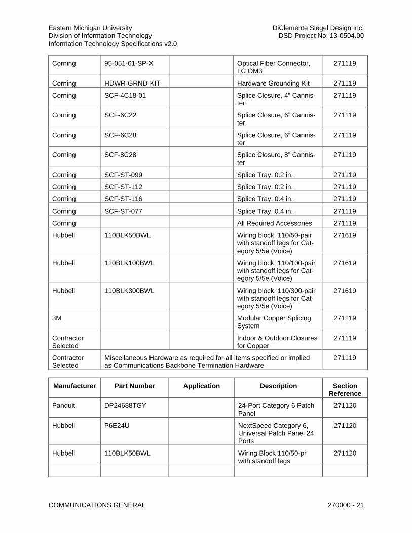
2.5 BASIS OF DESIGN AND REFERENCE PART NUMBERS
A. Basis of Design brands and part numbers listed herein are preferred by EMU. Alternates may be proposed but shall meet or exceed specifications for the items listed. Acceptance of products, other than those listed as approved, shall be at the sole discretion of the Owner’s Representative.
B. If a Bidder proposes to substitute an article, device, material, equipment, form of construction, fixture, or item other than the approved manufacturers and part numbers, listed and named in the Drawings and Specifications, the Bidder shall certify that the proposed item is equal in quality and all aspects of performance and appearance, to the items specified. The Bidder shall submit a request for Substitution to the Engineer/Designer no later than 10 days prior to the bid opening, which must include both: 1. The name and complete description of the proposed substitution including drawings,
performance and test data, and other information necessary for a complete evaluation. 2. A statement setting forth any changes that the proposed substitution will require in the
Contract Documents or the project.
C. If EMU approves the proposed substitution, the Engineer/Designer shall issue an Addendum.
D. If EMU does not approve the substitution, the Engineer/Designer shall inform the Bidder of its decision, which is final. EMU may reject a proposed Substitution because the Bidder failed to
Eastern Michigan University DiClemente Siegel Design Inc. Division of Information Technology DSD Project No. 13-0504.00 Information Technology Specifications v2.0
COMMUNICATIONS GENERAL 270000 - 17
provide sufficient information to enable the A/E to completely evaluate the Proposed Substitution without causing a delay in the scheduled bid opening.
E. Proposed Substitutions received by the Engineer/Designer less than 10 days prior to the bid opening shall not be considered.
F. Bidder shall confirm all reference part numbers, listed within Division 27, as current and suitable for the items described and specified and shall file a formal RFI for all perceived discrepancies prior to bidding.
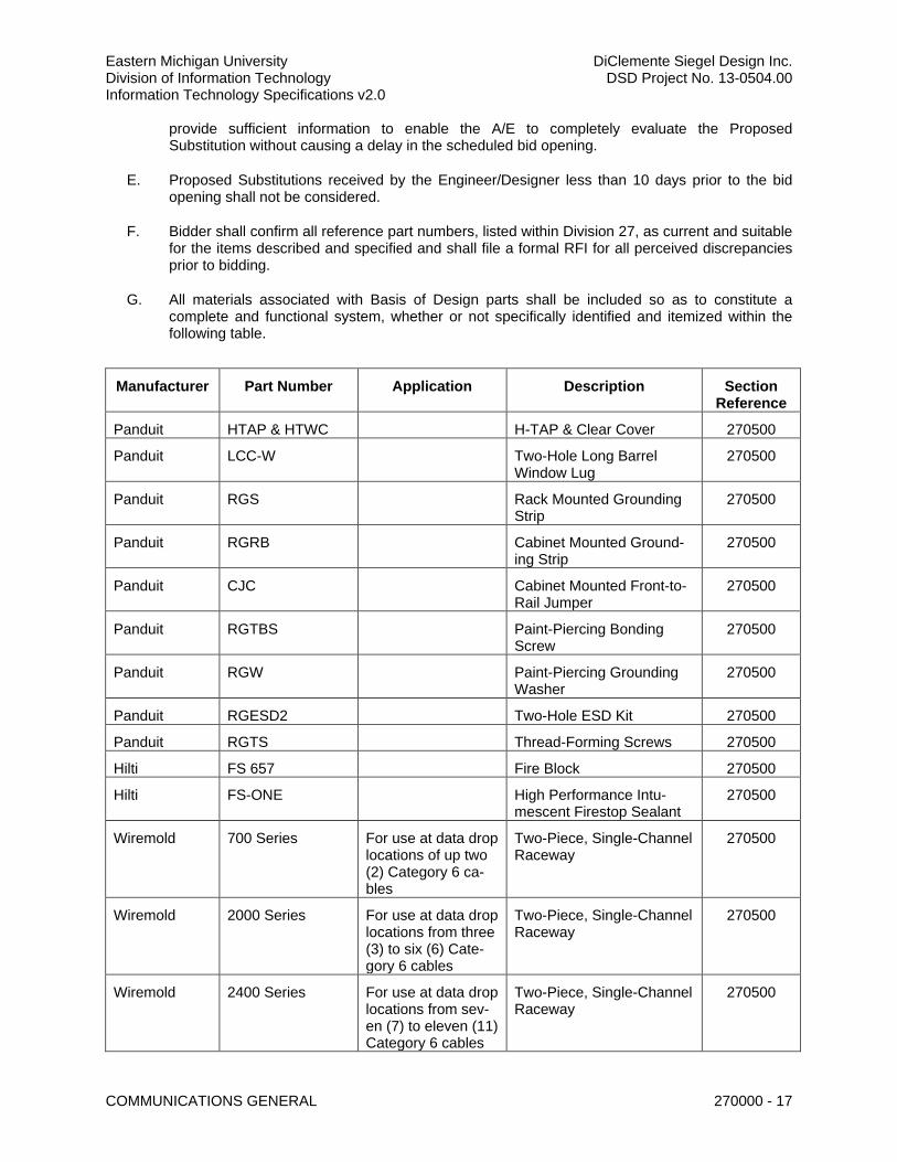
G. All materials associated with Basis of Design parts shall be included so as to constitute a complete and functional system, whether or not specifically identified and itemized within the following table.
Manufacturer Part Number Application Description Section Reference
Panduit HTAP & HTWC H-TAP & Clear Cover 270500
Panduit LCC-W Two-Hole Long Barrel Window Lug
270500
Panduit RGS Rack Mounted Grounding Strip
270500
Panduit RGRB Cabinet Mounted Ground-ing Strip
270500
Panduit CJC Cabinet Mounted Front-to-Rail Jumper
270500
Panduit RGTBS Paint-Piercing Bonding Screw
270500
Panduit RGW Paint-Piercing Grounding Washer
270500
Panduit RGESD2 Two-Hole ESD Kit 270500
Panduit RGTS Thread-Forming Screws 270500
Hilti FS 657 Fire Block 270500
Hilti FS-ONE High Performance Intu-mescent Firestop Sealant
270500
Wiremold 700 Series For use at data drop locations of up two (2) Category 6 ca-bles
Two-Piece, Single-Channel Raceway
270500
Wiremold 2000 Series For use at data drop locations from three (3) to six (6) Cate-gory 6 cables
Two-Piece, Single-Channel Raceway
270500
Wiremold 2400 Series For use at data drop locations from sev-en (7) to eleven (11) Category 6 cables
Two-Piece, Single-Channel Raceway
270500
Eastern Michigan University DiClemente Siegel Design Inc. Division of Information Technology DSD Project No. 13-0504.00 Information Technology Specifications v2.0
COMMUNICATIONS GENERAL 270000 - 18
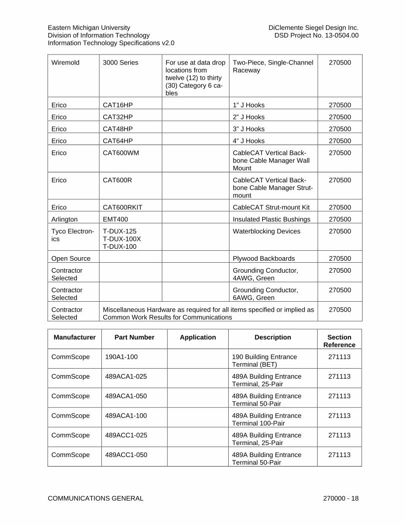
Wiremold 3000 Series For use at data drop locations from twelve (12) to thirty (30) Category 6 ca-bles
Two-Piece, Single-Channel Raceway
270500
Erico CAT16HP 1” J Hooks 270500
Erico CAT32HP 2” J Hooks 270500
Erico CAT48HP 3” J Hooks 270500
Erico CAT64HP 4” J Hooks 270500
Erico CAT600WM CableCAT Vertical Back-bone Cable Manager Wall Mount
270500
Erico CAT600R CableCAT Vertical Back-bone Cable Manager Strut-mount
270500
Erico CAT600RKIT CableCAT Strut-mount Kit 270500
Arlington EMT400 Insulated Plastic Bushings 270500
Tyco Electron-ics
T-DUX-125 T-DUX-100X T-DUX-100
Waterblocking Devices 270500
Open Source Plywood Backboards 270500
Contractor Selected
Grounding Conductor, 4AWG, Green
270500
Contractor Selected
Grounding Conductor, 6AWG, Green
270500
Contractor Selected
Miscellaneous Hardware as required for all items specified or implied as Common Work Results for Communications
270500
Manufacturer Part Number Application Description Section Reference
CommScope 190A1-100 190 Building Entrance Terminal (BET)
271113
CommScope 489ACA1-025 489A Building Entrance Terminal, 25-Pair
271113
CommScope 489ACA1-050 489A Building Entrance Terminal 50-Pair
271113
CommScope 489ACA1-100 489A Building Entrance Terminal 100-Pair
271113
CommScope 489ACC1-025 489A Building Entrance Terminal, 25-Pair
271113
CommScope 489ACC1-050 489A Building Entrance Terminal 50-Pair
271113
Eastern Michigan University DiClemente Siegel Design Inc. Division of Information Technology DSD Project No. 13-0504.00 Information Technology Specifications v2.0
COMMUNICATIONS GENERAL 270000 - 19
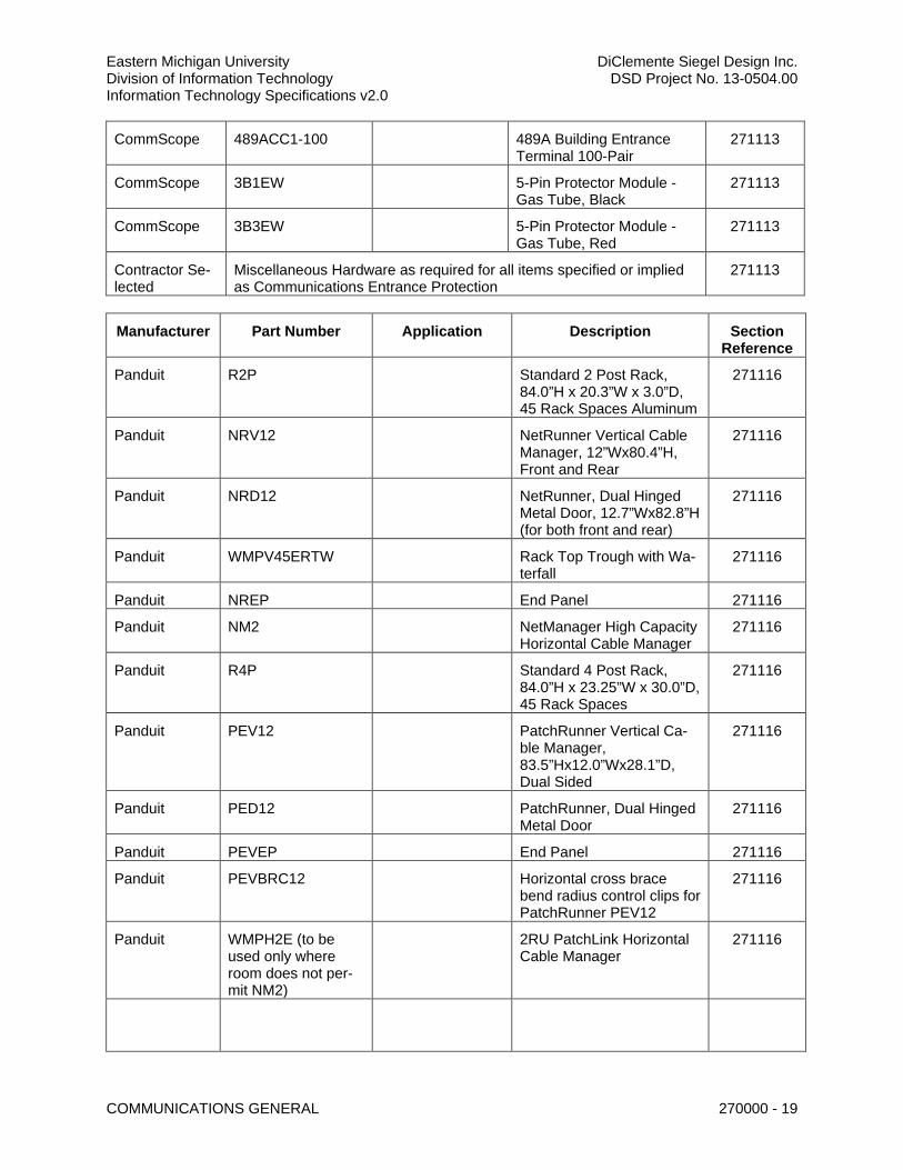
CommScope 489ACC1-100 489A Building Entrance Terminal 100-Pair
271113
CommScope 3B1EW 5-Pin Protector Module - Gas Tube, Black
271113
CommScope 3B3EW 5-Pin Protector Module - Gas Tube, Red
271113
Contractor Se-lected
Miscellaneous Hardware as required for all items specified or implied as Communications Entrance Protection
271113
Manufacturer Part Number Application Description Section Reference
Panduit R2P Standard 2 Post Rack, 84.0”H x 20.3”W x 3.0”D, 45 Rack Spaces Aluminum
271116
Panduit NRV12 NetRunner Vertical Cable Manager, 12”Wx80.4”H, Front and Rear
271116
Panduit NRD12 NetRunner, Dual Hinged Metal Door, 12.7”Wx82.8”H (for both front and rear)
271116
Panduit WMPV45ERTW Rack Top Trough with Wa-terfall
271116
Panduit NREP End Panel 271116
Panduit NM2 NetManager High Capacity Horizontal Cable Manager
271116
Panduit R4P Standard 4 Post Rack, 84.0”H x 23.25”W x 30.0”D, 45 Rack Spaces
271116
Panduit PEV12 PatchRunner Vertical Ca-ble Manager, 83.5”Hx12.0”Wx28.1”D, Dual Sided
271116
Panduit PED12 PatchRunner, Dual Hinged Metal Door
271116
Panduit PEVEP End Panel 271116
Panduit PEVBRC12 Horizontal cross brace bend radius control clips for PatchRunner PEV12
271116
Panduit WMPH2E (to be used only where room does not per-mit NM2)
2RU PatchLink Horizontal Cable Manager
271116
Eastern Michigan University DiClemente Siegel Design Inc. Division of Information Technology DSD Project No. 13-0504.00 Information Technology Specifications v2.0
COMMUNICATIONS GENERAL 270000 - 20
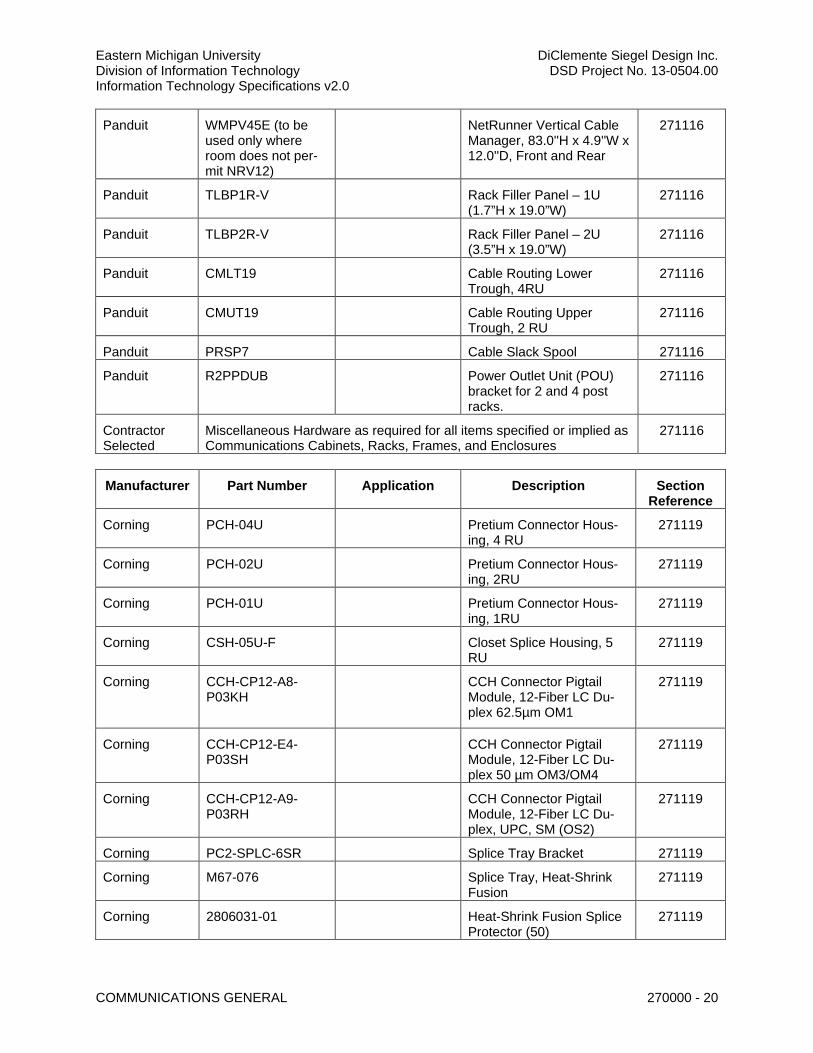
Panduit WMPV45E (to be used only where room does not per-mit NRV12)
NetRunner Vertical Cable Manager, 83.0''H x 4.9''W x 12.0''D, Front and Rear
271116
Panduit TLBP1R-V Rack Filler Panel – 1U (1.7”H x 19.0”W)
271116
Panduit TLBP2R-V Rack Filler Panel – 2U (3.5”H x 19.0”W)
271116
Panduit CMLT19 Cable Routing Lower Trough, 4RU
271116
Panduit CMUT19 Cable Routing Upper Trough, 2 RU
271116
Panduit PRSP7 Cable Slack Spool 271116
Panduit R2PPDUB Power Outlet Unit (POU) bracket for 2 and 4 post racks.
271116
Contractor Selected
Miscellaneous Hardware as required for all items specified or implied as Communications Cabinets, Racks, Frames, and Enclosures
271116
Manufacturer Part Number Application Description Section Reference
Corning PCH-04U Pretium Connector Hous-ing, 4 RU
271119
Corning PCH-02U Pretium Connector Hous-ing, 2RU
271119
Corning PCH-01U Pretium Connector Hous-ing, 1RU
271119
Corning CSH-05U-F Closet Splice Housing, 5 RU
271119
Corning CCH-CP12-A8-P03KH
CCH Connector Pigtail Module, 12-Fiber LC Du-plex 62.5µm OM1
271119
Corning CCH-CP12-E4-P03SH
CCH Connector Pigtail Module, 12-Fiber LC Du-plex 50 µm OM3/OM4
271119
Corning CCH-CP12-A9-P03RH
CCH Connector Pigtail Module, 12-Fiber LC Du-plex, UPC, SM (OS2)
271119
Corning PC2-SPLC-6SR Splice Tray Bracket 271119
Corning M67-076 Splice Tray, Heat-Shrink Fusion
271119
Corning 2806031-01 Heat-Shrink Fusion Splice Protector (50)
271119
Eastern Michigan University DiClemente Siegel Design Inc. Division of Information Technology DSD Project No. 13-0504.00 Information Technology Specifications v2.0
COMMUNICATIONS GENERAL 270000 - 21
Corning 95-051-61-SP-X Optical Fiber Connector, LC OM3
271119
Corning HDWR-GRND-KIT Hardware Grounding Kit 271119
Corning SCF-4C18-01 Splice Closure, 4” Cannis-ter
271119
Corning SCF-6C22 Splice Closure, 6” Cannis-ter
271119
Corning SCF-6C28 Splice Closure, 6” Cannis-ter
271119
Corning SCF-8C28 Splice Closure, 8” Cannis-ter
271119
Corning SCF-ST-099 Splice Tray, 0.2 in. 271119
Corning SCF-ST-112 Splice Tray, 0.2 in. 271119
Corning SCF-ST-116 Splice Tray, 0.4 in. 271119
Corning SCF-ST-077 Splice Tray, 0.4 in. 271119
Corning All Required Accessories 271119
Hubbell 110BLK50BWL Wiring block, 110/50-pair with standoff legs for Cat-egory 5/5e (Voice)
271619
Hubbell 110BLK100BWL Wiring block, 110/100-pair with standoff legs for Cat-egory 5/5e (Voice)
271619
Hubbell 110BLK300BWL Wiring block, 110/300-pair with standoff legs for Cat-egory 5/5e (Voice)
271619
3M Modular Copper Splicing System
271119
Contractor Selected
Indoor & Outdoor Closures for Copper
271119
Contractor Selected
Miscellaneous Hardware as required for all items specified or implied as Communications Backbone Termination Hardware
271119
Manufacturer Part Number Application Description Section Reference
Panduit DP24688TGY 24-Port Category 6 Patch Panel
271120
Hubbell P6E24U NextSpeed Category 6, Universal Patch Panel 24 Ports
271120
Hubbell 110BLK50BWL Wiring Block 110/50-pr with standoff legs
271120
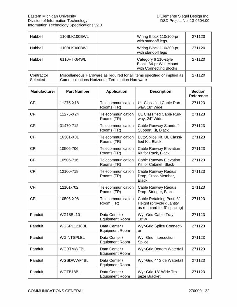
Eastern Michigan University DiClemente Siegel Design Inc. Division of Information Technology DSD Project No. 13-0504.00 Information Technology Specifications v2.0
COMMUNICATIONS GENERAL 270000 - 22
Hubbell 110BLK100BWL Wiring Block 110/100-pr with standoff legs
271120
Hubbell 110BLK300BWL Wiring Block 110/300-pr with standoff legs
271120
Hubbell 6110FTK64WL Category 6 110-style Block, 64-pr Wall Mount with Connecting Blocks
271120
Contractor Selected
Miscellaneous Hardware as required for all items specified or implied as Communications Horizontal Termination Hardware
271120
Manufacturer Part Number Application Description Section Reference
CPI 11275-X18 Telecommunication Rooms (TR)
UL Classified Cable Run-way, 18” Wide
271123
CPI 11275-X24 Telecommunication Rooms (TR)
UL Classified Cable Run-way, 24” Wide
271123
CPI 31470-712 Telecommunication Rooms (TR)
Cable Runway Standoff Support Kit, Black
271123
CPI 16301-X01 Telecommunication Rooms (TR)
Butt-Splice Kit, UL Classi-fied Kit, Black
271123
CPI 10506-706 Telecommunication Rooms (TR)
Cable Runway Elevation Kit for Rack, Black
271123
CPI 10506-716 Telecommunication Rooms (TR)
Cable Runway Elevation Kit for Cabinet, Black
271123
CPI 12100-718 Telecommunication Rooms (TR)
Cable Runway Radius Drop, Cross Member, Black
271123
CPI 12101-702 Telecommunication Rooms (TR)
Cable Runway Radius Drop, Stringer, Black
271123
CPI 10596-X08 Telecommunication Room (TR)
Cable Retaining Post, 8” Height (provide quantity as required for 9” spacing)
271123
Panduit WG18BL10 Data Center / Equipment Room
Wyr-Grid Cable Tray, 18”W
271123
Panduit WGSPL1218BL Data Center / Equipment Room
Wyr-Grid Splice Connect-or
271123
Panduit WGINTSPLBL Data Center / Equipment Room
Wyr-Grid Intersection Splice
271123
Panduit WGBTMWFBL Data Center / Equipment Room
Wyr-Grid Bottom Waterfall 271123
Panduit WGSDWWF4BL Data Center / Equipment Room
Wyr-Grid 4” Side Waterfall 271123
Panduit WGTB18BL Data Center / Equipment Room
Wyr-Grid 18” Wide Tra-peze Bracket
271123
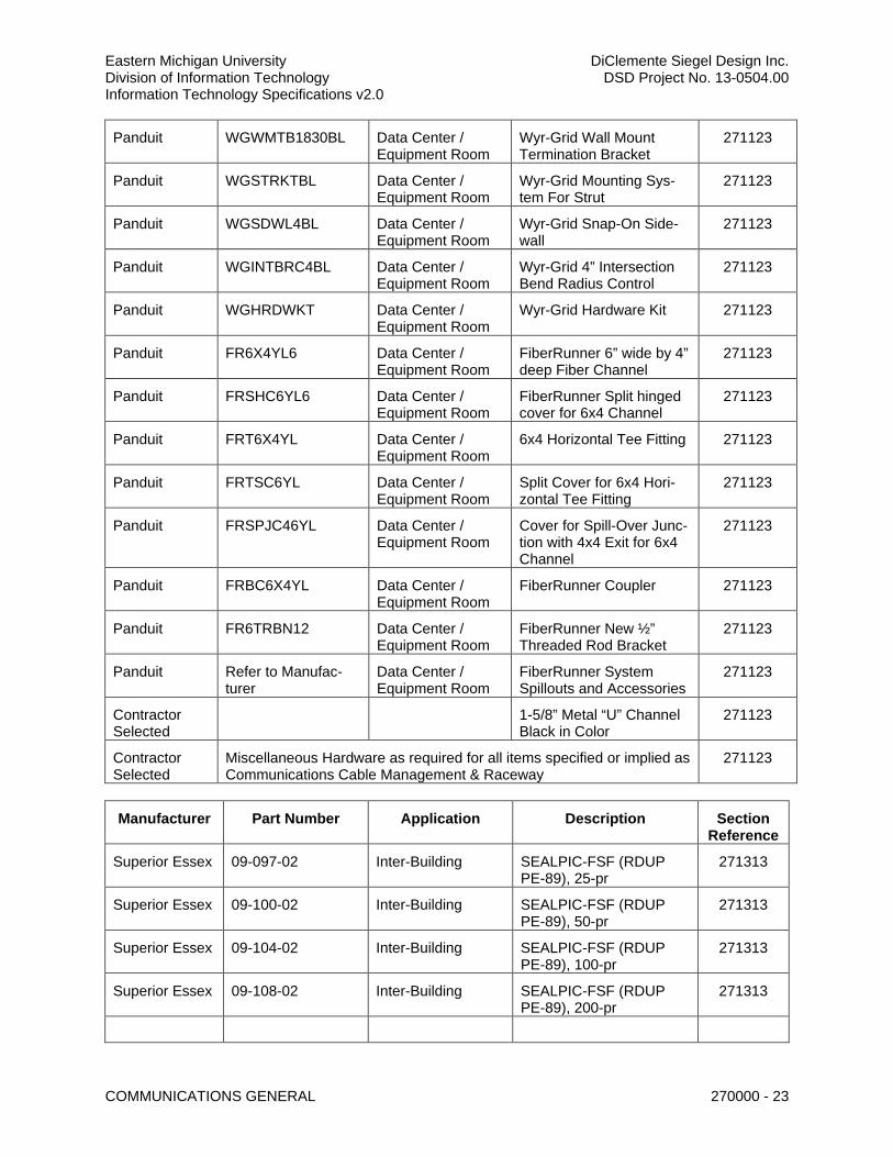
Eastern Michigan University DiClemente Siegel Design Inc. Division of Information Technology DSD Project No. 13-0504.00 Information Technology Specifications v2.0
COMMUNICATIONS GENERAL 270000 - 23
Panduit WGWMTB1830BL Data Center / Equipment Room
Wyr-Grid Wall Mount Termination Bracket
271123
Panduit WGSTRKTBL Data Center / Equipment Room
Wyr-Grid Mounting Sys-tem For Strut
271123
Panduit WGSDWL4BL Data Center / Equipment Room
Wyr-Grid Snap-On Side-wall
271123
Panduit WGINTBRC4BL Data Center / Equipment Room
Wyr-Grid 4” Intersection Bend Radius Control
271123
Panduit WGHRDWKT Data Center / Equipment Room
Wyr-Grid Hardware Kit 271123
Panduit FR6X4YL6 Data Center / Equipment Room
FiberRunner 6” wide by 4” deep Fiber Channel
271123
Panduit FRSHC6YL6 Data Center / Equipment Room
FiberRunner Split hinged cover for 6x4 Channel
271123
Panduit FRT6X4YL Data Center / Equipment Room
6x4 Horizontal Tee Fitting 271123
Panduit FRTSC6YL Data Center / Equipment Room
Split Cover for 6x4 Hori-zontal Tee Fitting
271123
Panduit FRSPJC46YL Data Center / Equipment Room
Cover for Spill-Over Junc-tion with 4x4 Exit for 6x4 Channel
271123
Panduit FRBC6X4YL Data Center / Equipment Room
FiberRunner Coupler 271123
Panduit FR6TRBN12 Data Center / Equipment Room
FiberRunner New ½” Threaded Rod Bracket
271123
Panduit Refer to Manufac-turer
Data Center / Equipment Room
FiberRunner System Spillouts and Accessories
271123
Contractor Selected
1-5/8” Metal “U” Channel Black in Color
271123
Contractor Selected
Miscellaneous Hardware as required for all items specified or implied as Communications Cable Management & Raceway
271123
Manufacturer Part Number Application Description Section Reference
Superior Essex 09-097-02 Inter-Building SEALPIC-FSF (RDUP PE-89), 25-pr
271313
Superior Essex 09-100-02 Inter-Building SEALPIC-FSF (RDUP PE-89), 50-pr
271313
Superior Essex 09-104-02 Inter-Building SEALPIC-FSF (RDUP PE-89), 100-pr
271313
Superior Essex 09-108-02 Inter-Building SEALPIC-FSF (RDUP PE-89), 200-pr
271313
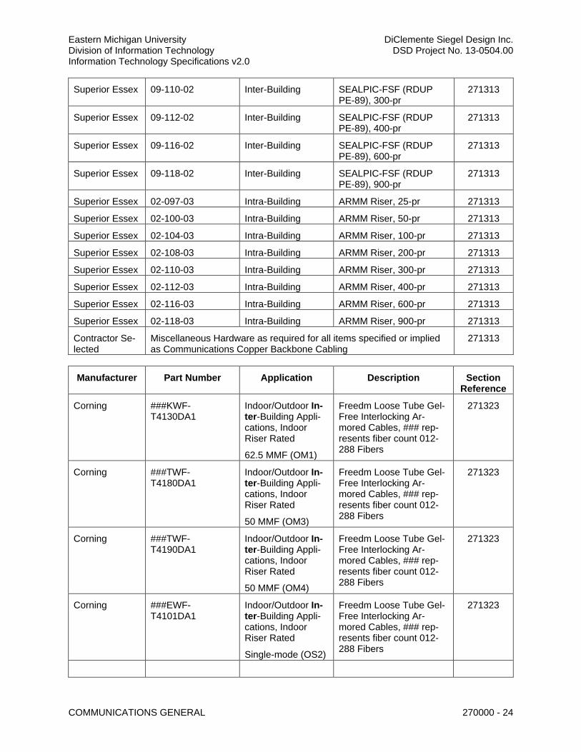
Eastern Michigan University DiClemente Siegel Design Inc. Division of Information Technology DSD Project No. 13-0504.00 Information Technology Specifications v2.0
COMMUNICATIONS GENERAL 270000 - 24
Superior Essex 09-110-02 Inter-Building SEALPIC-FSF (RDUP PE-89), 300-pr
271313
Superior Essex 09-112-02 Inter-Building SEALPIC-FSF (RDUP PE-89), 400-pr
271313
Superior Essex 09-116-02 Inter-Building SEALPIC-FSF (RDUP PE-89), 600-pr
271313
Superior Essex 09-118-02 Inter-Building SEALPIC-FSF (RDUP PE-89), 900-pr
271313
Superior Essex 02-097-03 Intra-Building ARMM Riser, 25-pr 271313
Superior Essex 02-100-03 Intra-Building ARMM Riser, 50-pr 271313
Superior Essex 02-104-03 Intra-Building ARMM Riser, 100-pr 271313
Superior Essex 02-108-03 Intra-Building ARMM Riser, 200-pr 271313
Superior Essex 02-110-03 Intra-Building ARMM Riser, 300-pr 271313
Superior Essex 02-112-03 Intra-Building ARMM Riser, 400-pr 271313
Superior Essex 02-116-03 Intra-Building ARMM Riser, 600-pr 271313
Superior Essex 02-118-03 Intra-Building ARMM Riser, 900-pr 271313
Contractor Se-lected
Miscellaneous Hardware as required for all items specified or implied as Communications Copper Backbone Cabling
271313
Manufacturer Part Number Application Description Section Reference
Corning ###KWF-T4130DA1
Indoor/Outdoor In-ter-Building Appli-cations, Indoor Riser Rated
62.5 MMF (OM1)
Freedm Loose Tube Gel-Free Interlocking Ar-mored Cables, ### rep-resents fiber count 012-288 Fibers
271323
Corning ###TWF-T4180DA1
Indoor/Outdoor In-ter-Building Appli-cations, Indoor Riser Rated
50 MMF (OM3)
Freedm Loose Tube Gel-Free Interlocking Ar-mored Cables, ### rep-resents fiber count 012-288 Fibers
271323
Corning ###TWF-T4190DA1
Indoor/Outdoor In-ter-Building Appli-cations, Indoor Riser Rated
50 MMF (OM4)
Freedm Loose Tube Gel-Free Interlocking Ar-mored Cables, ### rep-resents fiber count 012-288 Fibers
271323
Corning ###EWF-T4101DA1
Indoor/Outdoor In-ter-Building Appli-cations, Indoor Riser Rated
Single-mode (OS2)
Freedm Loose Tube Gel-Free Interlocking Ar-mored Cables, ### rep-resents fiber count 012-288 Fibers
271323
Eastern Michigan University DiClemente Siegel Design Inc. Division of Information Technology DSD Project No. 13-0504.00 Information Technology Specifications v2.0
COMMUNICATIONS GENERAL 270000 - 25
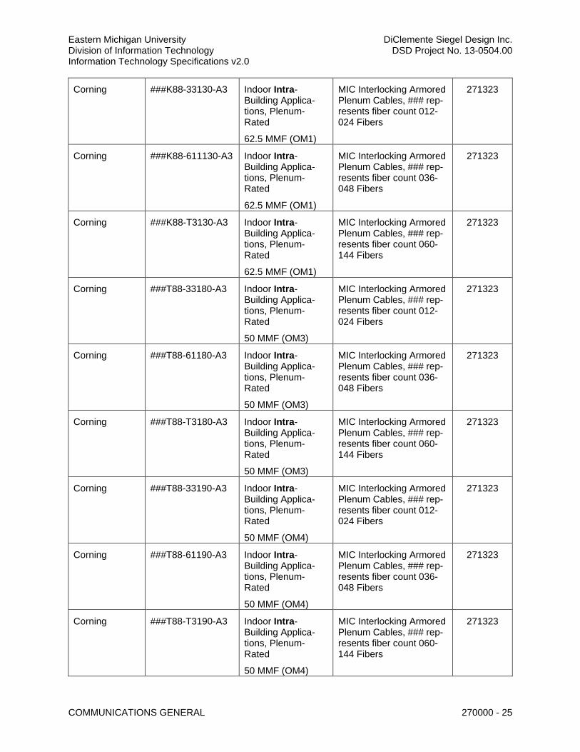
Corning ###K88-33130-A3 Indoor Intra-Building Applica-tions, Plenum-Rated
62.5 MMF (OM1)
MIC Interlocking Armored Plenum Cables, ### rep-resents fiber count 012-024 Fibers
271323
Corning ###K88-611130-A3 Indoor Intra-Building Applica-tions, Plenum-Rated
62.5 MMF (OM1)
MIC Interlocking Armored Plenum Cables, ### rep-resents fiber count 036-048 Fibers
271323
Corning ###K88-T3130-A3 Indoor Intra-Building Applica-tions, Plenum-Rated
62.5 MMF (OM1)
MIC Interlocking Armored Plenum Cables, ### rep-resents fiber count 060-144 Fibers
271323
Corning ###T88-33180-A3 Indoor Intra-Building Applica-tions, Plenum-Rated
50 MMF (OM3)
MIC Interlocking Armored Plenum Cables, ### rep-resents fiber count 012-024 Fibers
271323
Corning ###T88-61180-A3 Indoor Intra-Building Applica-tions, Plenum-Rated
50 MMF (OM3)
MIC Interlocking Armored Plenum Cables, ### rep-resents fiber count 036-048 Fibers
271323
Corning ###T88-T3180-A3 Indoor Intra-Building Applica-tions, Plenum-Rated
50 MMF (OM3)
MIC Interlocking Armored Plenum Cables, ### rep-resents fiber count 060-144 Fibers
271323
Corning ###T88-33190-A3 Indoor Intra-Building Applica-tions, Plenum-Rated
50 MMF (OM4)
MIC Interlocking Armored Plenum Cables, ### rep-resents fiber count 012-024 Fibers
271323
Corning ###T88-61190-A3 Indoor Intra-Building Applica-tions, Plenum-Rated
50 MMF (OM4)
MIC Interlocking Armored Plenum Cables, ### rep-resents fiber count 036-048 Fibers
271323
Corning ###T88-T3190-A3 Indoor Intra-Building Applica-tions, Plenum-Rated
50 MMF (OM4)
MIC Interlocking Armored Plenum Cables, ### rep-resents fiber count 060-144 Fibers
271323

Eastern Michigan University DiClemente Siegel Design Inc. Division of Information Technology DSD Project No. 13-0504.00 Information Technology Specifications v2.0
COMMUNICATIONS GENERAL 270000 - 26
Corning ###E88-33131-A3 Indoor Intra-Building Applica-tions, Plenum-Rated
Single-mode (OS2)
MIC Interlocking Armored Plenum Cables, ### rep-resents fiber count 012-024 Fibers
271323
Corning ###E88-61131-A3 Indoor Intra-Building Applica-tions, Plenum-Rated
Single-mode (OS2)
MIC Interlocking Armored Plenum Cables, ### rep-resents fiber count 036-048 Fibers
271323
Corning ###E88-T3131-A3 Indoor Intra-Building Applica-tions, Plenum-Rated
Single-mode (OS2)
MIC Interlocking Armored Plenum Cables, ### rep-resents fiber count 060-144 Fibers
271323
Contractor Se-lected
Miscellaneous Hardware as required for all items specified or implied as Communications Optical Fiber Backbone Cabling
271323
Manufacturer Part Number Application Description Section Reference
General Cable 7133800 GenSpeed 6 Category 6 Cable, CMR Non-Plenum Rated, Blue
271513
General Cable 7131800 GenSpeed 6 Category 6 Cable, CMP Plenum Rat-ed, Blue
271513
Mohawk M58804 6 LAN Plus Category 6 Cable, CMR Non-Plenum Rated, Blue
271513
Mohawk M58801 6 LAN Plus Category 6 Cable, CMP Plenum Rat-ed, Blue
271513
Corning 002T61-31180-24 Fan-Out Riser Cable, 2 Fibers, OM3
271513
Corning 002T68-31180-29 Fan-Out Plenum Cable, 2 Fibers, OM3
271513
Corning 004T61-31180-24 Fan-Out Riser Cable, 4 Fibers, OM3
271513
Corning 004T68-31180-29 Fan-Out Plenum Cable, 4 Fibers, OM3
271513
Panduit CLT150F-D20 Slit Corrugated Loom Tub-ing, Black Polyethylene, 1.55” I.D., 1.86” O.D.
271513
Contractor Selected
Miscellaneous Hardware as required for all Communications Horizontal Cabling
271513
Eastern Michigan University DiClemente Siegel Design Inc. Division of Information Technology DSD Project No. 13-0504.00 Information Technology Specifications v2.0
COMMUNICATIONS GENERAL 270000 - 27
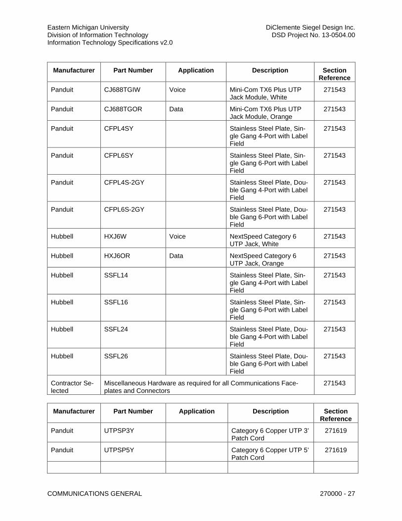
Manufacturer Part Number Application Description Section Reference
Panduit CJ688TGIW Voice Mini-Com TX6 Plus UTP Jack Module, White
271543
Panduit CJ688TGOR Data Mini-Com TX6 Plus UTP Jack Module, Orange
271543
Panduit CFPL4SY Stainless Steel Plate, Sin-gle Gang 4-Port with Label Field
271543
Panduit CFPL6SY Stainless Steel Plate, Sin-gle Gang 6-Port with Label Field
271543
Panduit CFPL4S-2GY Stainless Steel Plate, Dou-ble Gang 4-Port with Label Field
271543
Panduit CFPL6S-2GY Stainless Steel Plate, Dou-ble Gang 6-Port with Label Field
271543
Hubbell HXJ6W Voice NextSpeed Category 6 UTP Jack, White
271543
Hubbell HXJ6OR Data NextSpeed Category 6 UTP Jack, Orange
271543
Hubbell SSFL14 Stainless Steel Plate, Sin-gle Gang 4-Port with Label Field
271543
Hubbell SSFL16 Stainless Steel Plate, Sin-gle Gang 6-Port with Label Field
271543
Hubbell SSFL24 Stainless Steel Plate, Dou-ble Gang 4-Port with Label Field
271543
Hubbell SSFL26 Stainless Steel Plate, Dou-ble Gang 6-Port with Label Field
271543
Contractor Se-lected
Miscellaneous Hardware as required for all Communications Face-plates and Connectors
271543
Manufacturer Part Number Application Description Section Reference
Panduit UTPSP3Y Category 6 Copper UTP 3’ Patch Cord
271619
Panduit UTPSP5Y Category 6 Copper UTP 5’ Patch Cord
271619
Eastern Michigan University DiClemente Siegel Design Inc. Division of Information Technology DSD Project No. 13-0504.00 Information Technology Specifications v2.0
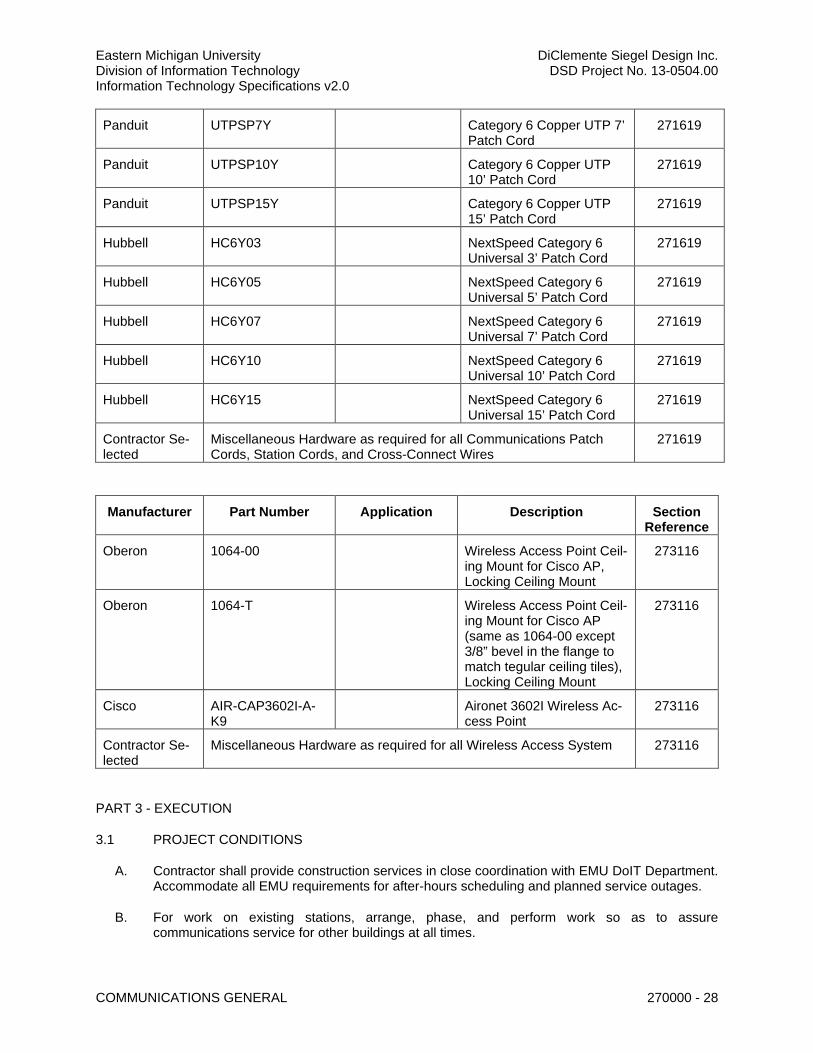
COMMUNICATIONS GENERAL 270000 - 28
Panduit UTPSP7Y Category 6 Copper UTP 7’ Patch Cord
271619
Panduit UTPSP10Y Category 6 Copper UTP 10’ Patch Cord
271619
Panduit UTPSP15Y Category 6 Copper UTP 15’ Patch Cord
271619
Hubbell HC6Y03 NextSpeed Category 6 Universal 3’ Patch Cord
271619
Hubbell HC6Y05 NextSpeed Category 6 Universal 5’ Patch Cord
271619
Hubbell HC6Y07 NextSpeed Category 6 Universal 7’ Patch Cord
271619
Hubbell HC6Y10 NextSpeed Category 6 Universal 10’ Patch Cord
271619
Hubbell HC6Y15 NextSpeed Category 6 Universal 15’ Patch Cord
271619
Contractor Se-lected
Miscellaneous Hardware as required for all Communications Patch Cords, Station Cords, and Cross-Connect Wires
271619
Manufacturer Part Number Application Description Section Reference
Oberon 1064-00 Wireless Access Point Ceil-ing Mount for Cisco AP, Locking Ceiling Mount
273116
Oberon 1064-T Wireless Access Point Ceil-ing Mount for Cisco AP (same as 1064-00 except 3/8” bevel in the flange to match tegular ceiling tiles), Locking Ceiling Mount
273116
Cisco AIR-CAP3602I-A-K9
Aironet 3602I Wireless Ac-cess Point
273116
Contractor Se-lected
Miscellaneous Hardware as required for all Wireless Access System 273116
PART 3 - EXECUTION
3.1 PROJECT CONDITIONS
A. Contractor shall provide construction services in close coordination with EMU DoIT Department. Accommodate all EMU requirements for after-hours scheduling and planned service outages.
B. For work on existing stations, arrange, phase, and perform work so as to assure communications service for other buildings at all times.

Eastern Michigan University DiClemente Siegel Design Inc. Division of Information Technology DSD Project No. 13-0504.00 Information Technology Specifications v2.0
COMMUNICATIONS GENERAL 270000 - 29
C. New work shall be installed and connected to existing work neatly and carefully. Disturbed or damaged work shall be replaced or repaired to its prior condition.
D. Remove and dispose of communications cabling, and other physical support elements, such as racks and panels, as required by construction phasing. Racks, panels, and electronic components shall be returned to EMU DoIT.
E. EMU shall not be responsible for delays in work because of shutdowns due to unsafe working practices by Contractors. Delays enforced by the safety officer caused by unforeseen environmental conditions in the work area may be out of Contractor’s control. Contractors shall contact the Project Manager immediately if delays are incurred for safety reasons.
F. Connectivity to all buildings is critical to the objectives of EMU. These objectives shall not be interrupted by the Contractor’s work activities. The active information transport system and cabling associated with specific work beyond the construction area shall not be disrupted at any time. Unusual circumstances (e.g. data cutovers) can occur and shall be declared and scheduled with as much notice as possible. Service disruptions, if needed, shall be at the convenience and schedule of EMU.
G. Security at EMU is controlled by the EMU Police Service. Security officers have final authority over access and security to specific work areas.
H. Contractor shall clean work areas each day and remove debris properly and legally from EMU property. Materials and supplies stored for use in the project shall be neatly stacked outside the circulation areas. All exits and paths shall be cleaned so as to prevent dirt from being tracked into EMU facilities.
I. Contractor shall ensure that all building fixtures have been re-installed to their original condition at the conclusion of the final shift of the day.
J. It shall be the responsibility of the Contractor to secure any parking permits prior to the first day of work on-site.
K. Work outside of normal EMU operating hours and days shall be coordinated with Owner’s Representative and Police Service.
3.2 SAFETY REQUIREMENTS
A. Job site safety and worker safety is the responsibility of the Contractor.
B. All contract work shall be performed in accordance with the policies, procedures, and standards established by the EMU Safety Office.
C. EMU safety officers have final authority over working conditions, required permits, and required equipment and its proper use. Contractors shall be responsible to coordinate their activities with the Safety Office.
D. In construction areas, all Contractor personnel shall wear personnel protection devices, as deemed appropriate by the Engineering and Facilities Management Department and as required by OSHA for the work location and work operation being performed. Devices shall included, but not be limited to hardhats, work boots, safety eye protection, reflective vests, etc.
E. All exposed holes, pits, pipes, etc., either inside or outside EMU facilities, shall be barricaded or plated and adequately secured when Contractor personnel are not present. All ladders, hanging
Eastern Michigan University DiClemente Siegel Design Inc. Division of Information Technology DSD Project No. 13-0504.00 Information Technology Specifications v2.0
COMMUNICATIONS GENERAL 270000 - 30
wires, pipes, and other items protruding at a pedestrian level travel way most be removed or secured following the final shift of the day.
F. During breaks or when only a portion of work has been completed, tools shall not be left exposed where others may risk injury or attempt to use them. Windows and doors shall not be left unsecured or propped open during breaks. At the completion of the final shift each day, doors, windows, or other openings shall be adequately secured.
G. Contractors shall provide the most stringent traffic control as specified by the State of Michigan, signage, etc. as needed to maintain a safe working environment. All work area access, road closures, parking spaces closures, and work outside of normal EMU operating hours and days shall be coordinated by Contractors as far in advance as possible with EMU Police Service. EMU Police shall determine if closures of roads or spaces are possible at proposed dates and times. Work at any location may be restricted by day or time, depending on the location of the area, the need for road closures/traffic control, and/or concurrent events in the area or on campus. Contractors should contact EMU Police well in advance to determine scheduling of access to work areas.
H. When driving on EMU property, Contractor personnel shall observe all traffic safety regulations and pay particular attention to pedestrians. All loose material and debris on vehicles shall be adequately secured and tied down.
3.3 PERSONNEL IDENTIFICATION
A. All Contractor personnel working on the project shall carry a valid company identification card and shall wear clothing that identifies their company name. This requirement shall be in effect throughout the duration of the project.
3.4 Contractor personnel may be required to wear EMU issued identification badges when performing work on EMU facilities. If required, the Contractor shall provide names and social security numbers of all personnel assigned to the project so that badges may be prepared. Upon completion of the project, EMU issued badges shall be returned to the EMU Police Service.
3.5 INSTALLATION AND REQUIREMENTS
A. Equipment location shall be as close as practical to locations shown on the Projects Drawings.
B. Inaccessible Equipment: 1. Where EMU determines that the Contractor has installed equipment not “conveniently
accessible” for operation and maintenance, the equipment shall be removed and re-installed as directed at no additional cost to EMU.
2. “Conveniently accessible” is defined as being capable of being reached without the use of ladders, or without climbing or crawling under or over obstacles such as, but not limited to, motors, pumps, belt guards, transformers, piping, ductwork, conduit, and raceways.
C. Consideration shall be given for operational efficiency and aesthetic factors in the installation of equipment and cables.
D. The data equipment (routers, switches, hubs, etc.) shall be furnished, installed and tested by EMU DoIT.
E. Cold-Weather Installation: Bring cable to manufacturer’s recommended installation temperature before dereeling. Heat lamps shall not be used for heating.
Eastern Michigan University DiClemente Siegel Design Inc. Division of Information Technology DSD Project No. 13-0504.00 Information Technology Specifications v2.0
COMMUNICATIONS GENERAL 270000 - 31
F. Care must be taken to ensure cables are not kinked, bent beyond limit, overloaded, over-cinched, crushed, improperly untwisted, etc.
3.6 USE OF THE SITE
A. Use of the site shall be at the Owners Representative direction in matters in which the Owner deems it necessary to place restriction.
B. Access to the building wherein the work is performed shall be as directed by the Owners Representative.
C. The premises may be occupied during the entire period of construction for conducting normal business operations. Cooperate with the Owners Representative to minimize conflict and to facilitate its operations.
D. Schedule necessary shutdowns of plant services with the Owners Representative, and obtain written permission. Refer to CONTINUITY OF SERVICES herein.
E. Proceed with the work without interfering with ordinary use of streets, aisles, passages, exits and operations of EMU.
3.7 CONTINUITY OF SERVICES
A. Take no action that will interfere with, or interrupt, existing building services unless previous arrangements have been made with the Owners Representative. Arrange the work to minimize shut down time.
B. The Owners personnel will perform shutdown of operating systems. The contractor shall give three (3) days’ advance notice for systems shutdown.
C. Should services be inadvertently interrupted, immediately furnish labor, including overtime, material, and equipment necessary for prompt restoration of interrupted service.
3.8 WARRANTY
A. The Structured Cabling Contractor shall be manufacturer certified for the system proposed and bid such as Panduit/General Cable NetGen Solution or Corning Cable Systems as an NPI (Network of Preferred Installers) partner and shall adhere to all warranty requirements for end-to-end installations.
B. The Contractor shall submit, in the bid documents, any additional Contractor-specific warranties or guarantees to be offered on the project.
C. The Contractor shall supply any and all necessary documentation needed to process and record the warranty(s) and to verify the installation solution.
D. Warranty of Fitness for a Particular Purpose 1. Cabling Contractor shall warrant recognition and understanding of all EMU requirements
and intended uses for the Division 27 systems, warrant the response to the bidding process, and warrant the equipment and all other products and services to satisfy all requirements identified in the contract documents as fit for the intended use unless specifically identified, in writing, in the bid response.
E. Warranty of Title
Eastern Michigan University DiClemente Siegel Design Inc. Division of Information Technology DSD Project No. 13-0504.00 Information Technology Specifications v2.0
COMMUNICATIONS GENERAL 270000 - 32
1. Contractor shall warrant the title to the equipment and software license rights to be free and clear of all liens, encumbrances, or agreements. Contractor further warrants and represents that in the event of any claim at any time; Contractor shall pay, satisfy, or make provision for the payment and satisfaction of any claim of any nature with respect to EMU shipping of any equipment.
F. System Warranty 1. All cabling systems shall be warranted for three (3) years for components, parts,
assemblies, and workmanship, and shall include a twenty five (25) year application assurance warranty as a manufacturer registered system installation. During the warranty period, and for non conformities of which Contractor has notice, Contractor shall take all necessary and appropriate action; free of charge, to correct any non-conformity with the warranties contained in the manufacturer agreement. During the warranty period, Contractor shall provide to EMU, free of costs and charges, all support necessary to ensure that the cabling system meets the requirements specified in this document and performance guarantees provided by the Contractors. During the warranty period, Contractors shall furnish, or cause to be furnished, all maintenance, service, parts, and replacements necessary to maintain the cabling system in good working condition, at no cost to EMU.
G. The Contractor shall supply a full manufacturer’s application assurance warranty for all new installations, to include approved termination hardware and cabling media from the proposed manufacturer’s list of approved materials. Services to be provided by this Contractor to EMU during the warranty period shall include, without limitation, the following. 1. Remedial Maintenance
a. Contractor shall provide service on EMU's site as necessary including, but not limited to, fault isolation, diagnosis, and repair.
2. Maintenance Records a. Contractor shall maintain, at the job site, a current record of the cabling system
configuration, including maintenance history and all adds, moves, and changes. 3. Replacement Parts 4. Contractor shall provide and install replacement parts, including new components, Field
Change Orders a. Contractor shall provide and install field change orders with EMU approval. All
change order requests shall be processed by the Project Manager. 5. Post-System Warranty Maintenance Service
a. Option of Maintenance Service 1) EMU shall reserve the right to elect or cancel at any time any maintenance
service to be provided by the Contractor. b. Warranty of On-Site Response
1) Regardless of the cause of the problem, Contractor shall ensure that parts, equipment, and materials are available to remedy the problems and its personnel are ready to begin work (such action being deemed a "response") within the contract time periods for the applicable warranty period or maintenance period.
6. Warranty of Security a. Contractor shall warrant that its personnel, including all subcontractors, shall at all
times comply with all EMU security regulations of which Contractor has been informed by EMU. Contractor also warrants that it has obtained all necessary licenses and permits required by federal, state, and local government.
Eastern Michigan University DiClemente Siegel Design Inc. Division of Information Technology DSD Project No. 13-0504.00 Information Technology Specifications v2.0
COMMUNICATIONS GENERAL 270000 - 33
3.9 FINAL CLEANING
A. Division 27 Contractor shall thoroughly clean all assemblies before they are turned over to EMU DoIT for operation. Cleaning shall include, but not be limited to, all cable runway, racks and wire managers (inside and out), copper and optical fiber panels (inside and out).
3.10 EMU APPROVED LABELING FORMATS
A. Labeling shall be furnished and applied to all components of Division 27 according to requirements listed in Part 3 of each section in formats as specifically directed by EMU DoIT. The Contractor shall make early contact with EU DoIT to verify any other special requirements for each project. Sample labels shall be made available upon request.
3.11 EQUIPMENT IDENTIFICATION
A. Install identification labels that clearly indicate information required for use and maintenance of equipment.
B. Namplates shall be laminated black phenolic resin with white core engraved lettering, a minimum of 6mm (1/4 inch) high. Secure nameplates with screws. Nameplates that are furnished by the manufacturer as a standard catalog item, or where another method of identification is specified herein, are exceptions.
3.12 TRAINING
A. Training shall be provided in accordance with Division 01 General Requirements, where project applicable.
B. Training shall be provided for the particular equipment or system as required in each associated specification section.
C. A training schedule shall be developed and submitted by the Contractor and approved by the Owner’s Representative at least thirty (30) days prior to the planned training.
END OF SECTION 270000
270500 - COMMON WORK RESULTS FOR COMMUNICATIONS
Eastern Michigan University DiClemente Siegel Design Inc. Division of Information Technology DSD Project No. 13-0504.00 Information Technology Specifications v2.0
COMMON WORK RESULTS FOR COMMUNICATIONS 270500 - 1
SECTION 270500 – COMMON WORK RESULTS FOR COMMUNICATIONS
PART 1 - GENERAL
1.1 RELATED DOCUMENTS
A. Drawings and general provisions of the Contract, including General and Supplementary Conditions and Division 00, Division 01, Division 02, and any others as publish by the Owner, apply to this Section, where project applicable.
B. Drawings and provisions of the Contract including Division 26 Electrical, where project applicable.
A. Section 270000 – Communications General
B. Section 270600 – Communications Underground Raceways & Structures
C. Section 271100 – Communications Equipment Room
D. Section 271113 – Communications Entrance Protection
E. Section 271116 – Communications Cabinets, Racks, Frames, & Enclosures
F. Section 271119 – Communications Backbone Termination Hardware
G. Section 271120 – Communications Horizontal Termination Hardware
H. Section 271123 – Communications Cable Management & Runway
I. Section 271313 – Communications Copper Backbone Cabling
J. Section 271323 – Communications Optical Fiber Backbone Cabling
K. Section 271513 – Communications Horizontal Cabling
L. Section 271543 – Communications Faceplates and Connectors
M. Section 271619 – Communications Patch Cords, Stations Cords and Cross-Connects
N. Section 273116 – Wireless Access System
1.2 CODES AND STANDARDS
A. Refer to Section 270000 – Communications General
B. Refer to Division 01, where project applicable.
1.3 SUMMARY
A. This Section includes: 1. Grounding and Bonding for Communications Systems 2. Hangers and Supports for Communications Systems
Eastern Michigan University DiClemente Siegel Design Inc. Division of Information Technology DSD Project No. 13-0504.00 Information Technology Specifications v2.0
COMMON WORK RESULTS FOR COMMUNICATIONS 270500 - 2
3. Cable Runways for Communications Systems 4. Surface Raceways for Communications Systems 5. Identification for Communications Systems 6. Cable Routing, Separation, and Distance 7. Communications Room Provisions 8. Common Installation Requirements 9. Firestopping
1.4 DEFINITIONS
A. Refer to Section 270000 – Communications General
1.5 ACRONYMS & ABBREVIATIONS
A. Refer to Section 270000 – Communications General
1.6 COORDINATION WITH OTHER TRADES
A. Coordinate layout of work with other trades. Make minor adjustments in location required for coordination. Locations of structural systems, heating work and plumbing lines shall take preference over locations of conduit lines where conflict occurs. Structural systems, heating work, and plumbing lines shall not interfere with or otherwise impede access to, and the routing of communication cabling with cable runway, raceways, or other pathways dedicated to communications. All potential issues shall be brought to the attention of the Project Manager immediately, before proceeding with installation.
B. Other than minor adjustments shall be submitted to the Project Manager for approval before proceeding with the work.
C. Coordinate locations, arrangement, mounting, and support of all communications provisions with Division 26. 1. To allow maximum possible headroom unless specific mounting heights that reduce
headroom are indicated. 2. To provide for ease of disconnecting the equipment with minimum interference to other
installations. 3. To allow right of way for piping and conduit installed at required slope. 4. So that connecting raceways, cables, wireways, cable runways, and busways will be
clear of obstructions and of the working and access space of other equipment.
D. Coordinate installation of required supporting devices and set sleeves in cast-in-place concrete, masonry walls, and other structural components as they are constructed.
E. Coordinate sleeve selection and application with selection and application of firestopping specified in Division 26.
F. Coordinate location of access panels and doors for electrical items that are behind finished surfaces or otherwise concealed.
1.7 SUBMITTALS
A. Refer to Section 270000 – Communications General
B. After approval and prior to installation, furnish the Owner’s Representative with one (1) sample of each of the following:
Eastern Michigan University DiClemente Siegel Design Inc. Division of Information Technology DSD Project No. 13-0504.00 Information Technology Specifications v2.0
COMMON WORK RESULTS FOR COMMUNICATIONS 270500 - 3
1. Each type of conduit and pathway coupling, bushing and termination fitting. 2. Raceways and pathway hangers, clamps and supports. 3. Runways and runway hangers, clamps and supports.
C. Shop drawings: 1. Shall include the location of system grounding electrode connections and the routing of
overhead and under floor grounding electrode conductors.
D. Test Reports: Provide certified test reports of ground resistance.
E. Certifications: Two (2) weeks prior to final inspection, submit four (4) copies of the following to the Owner’s Representative: 1. Certification that the grounding materials and installation is in accordance with the
drawings and specifications. 2. Certification, by the Contractor, that the complete grounding installation has been
properly installed and tested.
1.8 QUALITY ASSURANCE
A. Telecommunication Components, Devices, and Accessories: Listed and labeled as defined in NFPA 70, Article 100, by a testing agency acceptable to authorities having jurisdiction, and marked for intended use.
PART 2 - PRODUCTS
2.1 BASIS OF DESIGN REFERENCE PART NUMBERS
A. Bidder shall confirm all reference part numbers, listed within Division 27, as current and suitable for the items described and specified and shall file a formal RFI for all perceived discrepancies prior to bidding.
B. Refer to Section 270000 Communications General, Part 2.
2.2 GROUNDING AND BONDING
A. Materials: Comply with NFPA 70, ANSI/TIA/EIA-607, UL 83 and UL 467.
2.3 GROUNDING AND BONDING CONDUCTORS
A. Equipment grounding conductors shall be UL 83 insulated stranded copper, except that sizes 6 mm2 (10 AWG) and smaller shall be solid copper. Insulation color shall be continuous green for all equipment grounding conductors, except that wire sizes 25 mm2 (4 AWG) and larger shall be permitted to be identified per NEC.
B. Bonding conductors shall be ASTM B8 bare stranded copper, except that sizes 6 mm2 (10 AWG) and smaller shall be ASTM B1 solid bare copper wire.
2.4 SPLICES AND TERMINATION COMPONENTS
A. Components shall meet or exceed UL 467 and be clearly marked with the manufacturer, catalog number, and permitted conductor size(s).
Eastern Michigan University DiClemente Siegel Design Inc. Division of Information Technology DSD Project No. 13-0504.00 Information Technology Specifications v2.0
COMMON WORK RESULTS FOR COMMUNICATIONS 270500 - 4
2.5 SYSTEM GROUNDING BUSBARS
A. Busbars if non-existent shall be furnished and installed by Contractor, as specified herein.
1. TMGB (Telecommunications Main Grounding Busbar) shall be a pre-drilled solid copper busbar with two-hole lug connections for use with standard-sized lugs. Minimum dimensions shall be 6mm (0.25”) thick by 600mm by 100mm (4” wide and 24” in length). The TMGB shall be listed by a NRTL (Nationally Recognized Testing Laboratory).
2. TGB (Telecommunications Grounding Busbar) shall be a pre-drilled copper bus-bar with two-hole lug connections for use with standard-sized lugs. Minimum dimensions shall be 6mm (0.25”) thick by 100mm by 300mm (4” wide and 12” in length). The TGB shall be listed by a NRTL (Nationally Recognized Testing Laboratory).
2.6 GROUND CONNECTIONS
A. Overhead & Under Floor: 1. Bonding Jumpers: compression type connectors, using zinc-plated fasteners and external
tooth lock washers. 2. Ground Busbars: Two-hole compression type lugs using tin-plated copper or copper alloy
bolts and nuts 3. Rack and Cabinet Ground Bars: one-hole compression-type lugs using zinc-plated or
copper alloy fasteners.
2.7 EQUIPMENT RACK AND CABINET GROUND BARS
A. Furnish and install solid copper ground bars designed for mounting on the framework of open or cabinet- enclosed equipment racks with minimum dimensions of 4 mm thick by 19 mm wide (3/8 inch x 3/4 inch).
2.8 GROUND TERMINAL BLOCKS
A. At any equipment mounting location (e.g. backboards and hinged cover enclosures) where rack- type ground bars cannot be mounted, provide screw lug-type terminal blocks.
2.9 SPLICE CASE GROUND ACCESSORIES
A. Splice case grounding and bonding accessories shall be supplied by the splice case manufacturer when available. Otherwise, use 16mm2 (6 AWG) insulated ground wire with shield bonding connectors.
2.10 CABLE RUNWAYS
A. Refer to Section 271123 – Communications Cable Management and Runway
2.11 RACEWAYS
A. EMT: ANSI C80.3, zinc-coated steel, with set-screw or compression fittings.
B. FMC: Zinc-coated steel.
C. IMC: ANSI C80.6, zinc-coated steel, with threaded fittings.
D. LFMC: Zinc-coated steel with sunlight-resistant and mineral-oil-resistant plastic jacket.
Eastern Michigan University DiClemente Siegel Design Inc. Division of Information Technology DSD Project No. 13-0504.00 Information Technology Specifications v2.0
COMMON WORK RESULTS FOR COMMUNICATIONS 270500 - 5
E. RNC: NEMA TC 2, Schedule 40 PVC, with NEMA TC3 fittings.
F. Raceway Fittings: Specifically designed for the raceway type with which used.
G. METAL WIREWAYS
1. Manufacturers: Wiremold, Legrand, Hubbell 2. Material and Construction: Sheet metal sized and shaped as indicated, NEMA 1. 3. Fittings and Accessories: Include couplings, offsets, elbows, expansion joints, adapters,
hold-down straps, end caps, and other fittings to match and mate with wireways as required for complete system.
4. Select features, unless otherwise indicated, as required to complete wiring system and to comply with NFPA 70.
5. Wireway Covers: Flanged-and-gasketed type except as indicated otherwise. 6. Finish: Manufacturer's standard enamel finish.
2.12 SUPPORTING DEVICES
A. Material: Cold-formed steel, with corrosion-resistant coating acceptable to authorities having jurisdiction.
B. Metal Items for Use Outdoors or in Damp Locations: Hot-dip galvanized steel unless specified otherwise.
C. Miscellaneous Slotted-Steel Channel Supports: Flange edges turned toward web, and 9/16-inch diameter slotted holes at a maximum of 2 inches o.c., in webs.
D. Miscellaneous Slotted-Steel Channel Supports: Comply with requirements indicated for slotted channel framing.
1. Channel Thickness: Selected to suit structural loading. 2. Fittings and Accessories: Products of the same manufacturer as channel supports.
E. Nonmetallic Channel and Angle Systems: Structural-grade, factory-formed, glass-fiber-resin channels and angles with 9/16-inch diameter holes at a maximum of 8 inch o.c., in at least one surface.
1. Fittings and Accessories: Products of the same manufacturer as channels and angles. 2. Fittings and Accessory Materials: Same as channels and angles, except metal items
may be stainless steel.
F. Raceway and Cable Supports: Manufactured clevis hangers, riser clamps, straps, threaded C-clamps with retainers, ceiling trapeze hangers, wall brackets, and spring-steel clamps or click-type hangers, j-hooks, cable manager assemblies, etc.
G. Pipe Sleeves: ASTM A 53, Type E, Grade A, Schedule 40, galvanized steel, plain ends.
H. Cable Supports for Vertical Conduit: Factory-fabricated assembly consisting of threaded body and insulating wedging plug for nonarmored electrical cables in riser conduits. Plugs have number and size of conductor gripping holes as required to suit individual risers. Body constructed of malleable-iron casting with hot-dip galvanized finish.
I. Expansion Anchors: Carbon-steel wedge or sleeve type.

Eastern Michigan University DiClemente Siegel Design Inc. Division of Information Technology DSD Project No. 13-0504.00 Information Technology Specifications v2.0
COMMON WORK RESULTS FOR COMMUNICATIONS 270500 - 6
J. Toggle Bolts: All-steel springhead type.
K. Powder-Driven Threaded Studs: Heat-treated steel.
2.13 IDENTIFICATION
A. Materials by Brady, Brother, and Panduit in compliance with ANSI/TIA/EIA-606-A, Administration Standard for Commercial Telecommunications Infrastructure
2.14 CONDUIT CHASE PIPES
A. Conduit Chase Pipes shall be provided within the telecommunication space in any case where ceiling tile has been provided and must be breached.
B. Electrical Metallic Tubing (EMT) and Fittings 1. 4” trade size
a. Manufactured to ANSI C80.3 (EMT Zinc Coated) b. UL Standard 797 (EMT – Steel)
2. Arlington insulated bushings
2.15 FIRESTOP DEVICES
A. The approved pathway through wall penetrations, up to 8” thick, is the E-Z Path (sleeve system) by STI. The Contractor shall identify penetration points for horizontal cabling, but must obtain pre-approval from EMU Physical Plant prior to installation.
B. For wall penetrations thicker than 8”, the use of metallic conduit shall be approved. Metallic conduit sleeves shall be 4” minimum.
C. For cable basket/tray penetrations through rated walls, intumescent firestop pillows shall be in-stalled. E-Z Path Series SSB Firestop Pillows or the equivalent.
D. For floor penetrations thicker than 8”, the use of metallic conduit shall be approved. Metallic conduit sleeves shall be 4” minimum.
2.16 TOUCHUP PAINT
A. For Equipment: Equipment manufacturer’s paint selected to match installed equipment finish.
B. Galvanized Surfaces: Zinc-rich paint recommended by item manufacturer.
PART 3 - EXECUTION
3.1 FIELD CONDITIONS
A. Examine all elements intended for Communications. Check pathways, raceways, cable runways, and other elements for compliance with space allocations, installation tolerances, installation hazards or impediments, and other conditions affecting installation. Verify that all work required in the field is adequately described in the plans. Proceed with installation only after unsatisfactory conditions and discrepancies have been brought to the attention of the Project Manager and corrected.
Eastern Michigan University DiClemente Siegel Design Inc. Division of Information Technology DSD Project No. 13-0504.00 Information Technology Specifications v2.0
COMMON WORK RESULTS FOR COMMUNICATIONS 270500 - 7
B. Unless otherwise noted, the footages for cabling and materials shown on the Project Drawings are based upon available plant records, architectural drawings, or the Engineer/Designer’s route and pathway assumptions. The Contractor shall be required to perform field surveys and measurements, prior to ordering materials.
3.2 GROUNDING AND BONDING - GENERAL
A. An approved grounding system, as specified herein, shall always be required in each communications space; EF, TR, DC, ER and any other information transport systems distribution space.
B. All grounding and bonding systems for communications shall be carefully reviewed and pre-approved by EMU Physical Plant in cooperation with EMU DoIT Department. It is possible that new construction provisions may need to be enhanced for additional capacity, beyond the scope of a current project, to address the overall building needs.
C. All communications rack, cable runway, and equipment grounding shall be furnished and installed by the Division 27 Contractor.
D. Equipment Grounding: Metallic structures (including ductwork and building steel), enclosures, raceways, junction boxes, outlet boxes, cabinets, machine frames, and other conductive items in close proximity with electrical circuits shall be bonded and grounded.
E. Route conductors on short direct paths that have minimum resistive and inductive impedance as follows:
a. Bonding conductors shall be routed with minimum bends or changes in direction. b. Bonding connections shall be made directly to the points being bonded. c. Do not bend the grounding conductor wires into tight angles. Changes in direction
shall be of the widest radius possible. d. Unnecessary connections or splices in bonding conductors shall be avoided. When
absolutely necessary, use an approved connection and position it in an accessible location.
3.3 INACCESSIBLE GROUNDING CONNECTIONS
A. Make grounding connections, which are otherwise normally inaccessible (except connections for which periodic testing access is required) by exothermic weld.
3.4 CORROSION INHIBITORS
A. When making ground and ground bonding connections, apply a corrosion inhibitor to all contact surfaces. Use corrosion inhibitor appropriate for protecting a connection between the metals used.
3.5 TELECOMMUNICATIONS SYSTEM
A. Bond telecommunications system grounding equipment to the electrical grounding electrode system.
B. Furnish and install all wire and hardware required to properly ground, bond and connect communications raceway, cable runway, metallic cable shields, and equipment to an approved ground source.
Eastern Michigan University DiClemente Siegel Design Inc. Division of Information Technology DSD Project No. 13-0504.00 Information Technology Specifications v2.0
COMMON WORK RESULTS FOR COMMUNICATIONS 270500 - 8
C. Ground bonding jumpers shall be continuous with no splices. Use the shortest length of bonding jumper possible.
D. Provide ground paths that are permanent and continuous with a resistance of 1 ohm or less from raceway, cable runway, and equipment connections to the building grounding electrode. The resistance across individual bonding connections shall be 10 milliohms or less.
E. When making bolted or screwed connections to attach bonding jumpers, remove paint to expose the entire contact surface by grinding where necessary; thoroughly clean all connector, plate and other contact surfaces; and apply an appropriate corrosion inhibitor to all surfaces before joining.
F. Bonding Jumpers: 1. Use insulated ground wire of the size and type shown on the Drawings or use a minimum
of 16 mm2 (6 AWG) insulated copper wire. 2. Assemble bonding jumpers using insulated ground wire terminated with compression
connectors. 3. Use compression connectors of proper size for conductors specified. Use connector
manufacturer’s compression tool.
G. Bonding Jumper Fasteners: 1. Conduit: Fasten bonding jumpers using screw lugs on grounding bushings or conduit
strut clamps, or the clamp pads on push-type conduit fasteners. When screw lug connection to a conduit strut clamp is not possible, fasten the plain end of a bonding jumper wire by slipping the plain end under the conduit strut clamp pad; tighten the clamp screw firmly. Where appropriate, use zinc-plated external tooth lock washers.
2. Wireway and Cable Runway: Fasten bonding jumpers using zinc-plated bolts, external tooth lock washers, and nuts. Install protective cover, e.g., zinc-plated acorn nuts on any bolts extending into wireway or cable runway to prevent cable damage.
3. Ground Plates and Busbars: Fasten bonding jumpers using two-hole compression lugs. Use tin-plated copper or copper alloy bolts, external tooth lock washers, and nuts.
4. Unistrut and Raised Floor Stringers: Fasten bonding jumpers using zinc-plated, self-drill screws and external tooth lock washers.
3.6 GROUNDING AND BONDING - DATA CENTER (DC) AND EQUIPMENT ROOMS (ER)
A. Telecommunications Ground Busbars (TGB): 1. Provide communications room telecommunications ground busbar hardware at 950 mm
(18 inches) if non-existent. 2. Connect the telecommunications room ground busbars to other room grounding busbars
as indicated on the Telecommunications Grounding Busbar detail in the drawings.
B. Self-Supporting and Cabinet-Mounted Equipment Rack Ground Bars: 1. When ground bars are provided at the rear of lineup of bolted together equipment racks,
bond the copper ground bars together using solid copper splice plates supplied by the ground bar manufacturer.
2. Bond together nonadjacent ground bars on equipment racks and cabinets with 16 mm2 (6 AWG) insulated copper wire bonding jumpers attached at each end with compression-type connectors and mounting bolts.
3. Provide a 16 mm2 (6 AWG) bonding jumper between the rack and/or cabinet ground busbar and the aluminum pan of an overhead cable runway or the raised floor stringer as appropriate.
C. Other Communication Room Ground Systems: Ground all metallic conduit, wireways, and other metallic equipment located away from equipment racks or cabinets to the common bonding
Eastern Michigan University DiClemente Siegel Design Inc. Division of Information Technology DSD Project No. 13-0504.00 Information Technology Specifications v2.0
COMMON WORK RESULTS FOR COMMUNICATIONS 270500 - 9
network or the telecommunications ground busbar, whichever is closer, using insulated 16 mm2 (6 AWG) ground wire bonding jumpers.
3.7 STRUCTURED GROUNDING SYSTEM FOR NETWORK EQUIPMENT
A. Structured grounding system shall provide a low resistance, verifiable, dedicated path to a locally provided TGB for purposes of maintaining performance, protection, and network reliability.
B. Spaces designed to support rack mounted network equipment shall require a structured grounding system to which all communications rack, cabinet, cable runway, wall frame, and equipment grounding shall be terminated.
C. All open frame rack assemblies and cabinets shall require vertical rack grounding strips (RGS). Strips shall be mounted on the back side of the vertical rack rails for two-post assemblies and on the back side of the front post for four-post assemblies. These mounting arrangements apply to racks based on both UTP and F/UTP cabling. Contractor shall confirm details with EMU DoIT Department prior to proceeding with the installation.
D. Furnish and install equipment including, but not limited to: 1. Common Bonding Network 2. Copper Compression HTAP(s) 3. Copper Compression Two-Hole Lugs 4. Rack-Mounted Grounding Strips(s) 5. Cabinet-mounted Front-to-Rail Jumper(s) 6. Paint-piercing Bonding Screws and Studs 7. Paint-piercing Grounding Washers 8. ESD (Electrostatic Discharge) Studs and Static Wrist Straps (on per rack or cabinet).
3.8 COMMUNICATIONS CABLE BASKET AND RUNWAY SYSTEMS
A. Bond the metallic structures of one cable runway in each runway run following the same path to provide 100 percent electrical continuity throughout these cable runway systems as follows: 1. Splice plates provided by the cable runway manufacturer can be used for providing a
ground bonding connection between cable runway sections when the resistance across a bolted connection is 10 milliohms or less. The Subcontractor shall verify this loss by testing across one slice plate connection in the presence of the Contractor.
2. Install a 16 mm2 (6 AWG) bonding jumper across each cable runway splice or junction where splice plates cannot be used.
3. When cable runway terminations to cable rack, install 16 mm2 (6 AWG) bonding jumper between cable runway and cable rack pan.
3.9 COMMUNICATIONS RACEWAY GROUNDING
A. Conduit: Use insulated 16 mm2 (6 AWG) bonding jumpers to ground metallic conduit at each end and to bond at all intermediate metallic enclosures.
B. Wireway: use insulated 16 mm2 (6 AWG) bonding jumpers to ground or bond metallic wireway at each end at all intermediate metallic enclosures and across all section junctions.
C. Cable Tray Systems: Use insulated 16 mm2 (6 AWG) bonding jumpers to ground cable tray to column-mounted building ground plates (pads) at each end and approximately every 16 meters (50 feet).
Eastern Michigan University DiClemente Siegel Design Inc. Division of Information Technology DSD Project No. 13-0504.00 Information Technology Specifications v2.0
COMMON WORK RESULTS FOR COMMUNICATIONS 270500 - 10
3.10 GROUND RESISTANCE
A. Grounding system resistance to ground shall not exceed 5 ohms. Make necessary modifications or additions to the grounding electrode system for compliance without additional cost to EMU. Final tests shall assure that this requirement is met.
B. Resistance of the grounding electrode system shall be measured using a four-terminal fall-of-potential method as defined in IEEE 81. Ground resistance measurements shall be made before the electrical distribution system is energized and shall be made in normally dry conditions not less than 48 hours after the last rainfall. Resistance measurements of separate grounding electrode systems shall be made before the systems are bonded together below grade. The combined resistance of separate systems may be used to meet the required resistance, but the specified number of electrodes must still be provided.
C. Services at power company interface points shall comply with the power company ground resistance requirements.
3.11 HANGERS AND SUPPORTS
A. Where conduit, cable runways, or raceways are not provided, Division 27 shall furnish and install independent supports so that no cable rests directly on ceiling tile, mechanical ductwork, or other supporting structures.
B. Communications cabling shall be contained within a combination of open spaces, enclosed conduits, raceways, and cable runways. These pathways are designed to provide the capacity to properly install high performance communications cabling for present and future applications.
C. Cables shall be neatly routed and bundled in bundles limited to a quantity of cables as per manufacturer specifications and installation practices for Category 6 UTP or F/UTP as applicable to the media being installed.
D. Suspended ceiling support wires shall not be used for cabling support. Cables shall not be laid directly on ceiling tiles or rails. Cables placed in hangers in the ceiling area shall be routed high and away from all other electrical and mechanical systems so as to avoid contact with light fixtures, ventilation ducts, sprinkler system or plumbing piping, motors or any other electrical devices.
E. The maximum separation between support points for all cabling shall be five (5) feet
F. All cable pathway support elements shall be certified by the manufacturer for a high performance twisted pair installation, when applicable. In all cases, support products shall be approved for the support of Category 6 or higher cables, including optical fiber.
3.12 CABLE RUNWAY
A. Refer to Section 271123 – Communications Cable Management and Runway
3.13 SURFACE RACEWAYS
A. Use the following raceways for outdoor installations:
1. Exposed: IMC. 2. Concealed: IMC. 3. Underground, Grouped: RNC.
Eastern Michigan University DiClemente Siegel Design Inc. Division of Information Technology DSD Project No. 13-0504.00 Information Technology Specifications v2.0
COMMON WORK RESULTS FOR COMMUNICATIONS 270500 - 11
4. Connection to Vibrating Equipment: LFMC. 5. Boxes and Enclosures: NEMA 250, Type 3R or Type 4. 6. Underground ductbank and manhole system.
B. Use the following raceways for indoor installations:
1. Exposed: EMT. 2. Concealed: EMT. 3. Connection to Vibrating Equipment: FMC; except in wet or damp locations, use LFMC. 4. Damp or Wet Locations: IMC. 5. Boxes and Enclosures: NEMA 250, Type 1, unless otherwise indicated. 6. Metal wireways and fittings.
C. Use the following raceways for steam tunnel installations:
1. Rigid PVC Schedule 40 2. Plastic coated rigid galvanized steel conduit.
3.14 RACEWAY AND CABLE INSTALLATION
A. Conceal raceways and cables, unless otherwise indicated, within finished walls, ceilings, and floors.
B. Install raceways and cables at least 6 inches away from parallel runs of flues and steam or hot-water pipes. Locate horizontal raceway runs above water and steam piping.
C. Use temporary raceway caps to prevent foreign matter from entering.
D. Make conduit bends and offsets so ID is not reduced. Keep legs of bends in the same plane and straight legs of offsets parallel, unless otherwise indicated.
E. Use raceway and cable fittings compatible with raceways and cables and suitable for use and location.
F. Install pull wires in empty raceways. Use plastic or nylon line with not less than 200-lb tensile strength. Leave at least 12 inches of slack at each end of the pull wire.
G. If a conduit run is over a hundred feet in length or contains more than two 90 degree bends, a pullbox is required, the location of which must be approved by the Engineer/Designer.
H. A third bend may be acceptable in a pull section without derating the conduit’s capacity if one of the following conditions is true:
· The total run is not longer than 10m (33 ft) · The conduit size is increased to the next trade size · One of the bends is located within 12” of the cable feed end (this exception applies
to placing operations where cable is pushed around the first bend)
3.15 SUPPORTING DEVICE APPLICATION
A. Damp Locations and Outdoors: Hot-dip galvanized materials or nonmetallic, U-channel system components.
B. Dry Locations: Steel materials.

Eastern Michigan University DiClemente Siegel Design Inc. Division of Information Technology DSD Project No. 13-0504.00 Information Technology Specifications v2.0
COMMON WORK RESULTS FOR COMMUNICATIONS 270500 - 12
C. Support Clamps for PVC Raceways: Click-type clamp system.
D. Selection of Supports: Comply with manufacturer's written instructions.
E. Strength of Supports: Adequate to carry present and future loads, times a safety factor of at least four; minimum of 200-lb design load.
3.16 SUPPORT INSTALLATION
A. Install support devices to securely and permanently fasten and support telecommunication components.
B. Install individual and multiple raceway hangers and riser clamps to support raceways. Provide U-bolts, clamps, attachments, and other hardware necessary for hanger assemblies and for securing hanger rods and conduits.
C. Support parallel runs of horizontal raceways together on trapeze- or bracket-type hangers.
D. Size supports for multiple raceway installations so capacity can be increased by a 25 percent minimum in the future.
E. Support individual horizontal raceways with separate, malleable-iron pipe hangers or clamps.
F. Install 1/4-inch- diameter or larger threaded steel hanger rods, unless otherwise indicated.
G. Spring-steel fasteners specifically designed for supporting single conduits or tubing may be used instead of malleable-iron hangers for 1-1/2-inch and smaller raceways serving lighting and receptacle branch circuits above suspended ceilings and for fastening raceways to slotted channel and angle supports.
H. Arrange supports in vertical runs so the weight of raceways and enclosed conductors is carried entirely by raceway supports, with no weight load on raceway terminals.
I. Simultaneously install vertical conductor supports with conductors.
J. Install metal channel racks for mounting cabinets, pull and junction boxes and other devices unless components are mounted directly to structural elements of adequate strength.
K. Install sleeves for cable and raceway penetrations of concrete slabs and walls unless core-drilled holes are used. Install sleeves for cable and raceway penetrations of masonry and fire-rated gypsum walls and of all other fire-rated floor and wall assemblies. Install sleeves during erection of concrete and masonry walls.
L. Securely fasten telecommunication items and their supports to the building structure, unless otherwise indicated. Perform fastening according to the following unless other fastening methods are indicated:
1. Wood: Fasten with wood screws or screw-type nails. 2. Masonry: Toggle bolts on hollow masonry units and expansion bolts on solid masonry
units. 3. New Concrete: Concrete inserts with machine screws and bolts. 4. Existing Concrete: Expansion bolts. 5. Instead of expansion bolts, threaded studs driven by a powder charge and provided with
lock washers may be used in existing concrete.

Eastern Michigan University DiClemente Siegel Design Inc. Division of Information Technology DSD Project No. 13-0504.00 Information Technology Specifications v2.0
COMMON WORK RESULTS FOR COMMUNICATIONS 270500 - 13
6. Steel: Welded threaded studs or spring-tension clamps on steel. a. Field Welding: Comply with AWS D1.1.
7. Welding to steel structure may be used only for threaded studs, not for conduits, pipe straps, or other items.
8. Light Steel: Sheet-metal screws. 9. Fasteners: Select so the load applied to each fastener does not exceed 25 percent of its
proof-test load.
3.17 IDENTIFICATION
A. Install at locations for most convenient viewing without interference with operation and maintenance of equipment.
B. All cables, conductors, racks, cabinets, frame, and panels shall be labeled as per the requirements of ANSI/TIA/EIA-606-A, Administration Standard for Commercial Telecommunications Infrastructure.
3.18 COMMON INSTALLATION REQUIREMENTS
A. Measure indicated mounting heights to bottom of unit for suspended items and to center of unit for wall mounting items.
B. Headroom Maintenance: If mounting heights or other location criteria are not indicated, arrange and install components and equipment to provide maximum possible headroom consistent with these requirements.
C. Equipment: Install to facilitate service, maintenance, and repair or replacement of components of both electrical equipment and other nearby installations. Connect in such a way as to facilitate future disconnecting with minimum interference with other items in the vicinity.
D. Right of Way: Give to piping systems installed at a required slope.
E. The Contractor shall contact EMU before commencement of work and shall coordinate with EMU personnel and all other trades. Commencement of work shall be coordinated through the Project Manager.
3.19 CABLE ROUTING, SEPARATION, AND DISTANCE
A. Whenever possible, primary cable routing paths shall follow the logical structure of the building. When a wall must be breached, provide sleeved openings. Cabling shall enter and exit these areas at 90° angles. Route all cables and cable raceways parallel to or perpendicular to building structure. No diagonal runs shall be permitted, unless noted otherwise.
B. To reduce or eliminate the field effect of EMI on data signaling, cable runs shall be kept a minimum distance from EMI sources. Refer to ANSI/NECA/BICSI-568-2006 Standard for Installing Commercial Building Telecommunications Cabling.
1. Minimum separation distance from possible sources of EMI: a. 5 inches (125mm) from power lines of 2 KVA or less. b. 12 inches (305mm) from lighting fixtures.
2. Minimum separation distance from possible sources of EMI exceeding 5KVA:
Eastern Michigan University DiClemente Siegel Design Inc. Division of Information Technology DSD Project No. 13-0504.00 Information Technology Specifications v2.0
COMMON WORK RESULTS FOR COMMUNICATIONS 270500 - 14
Condition Min. Separation Dis-tance
Unshielded power lines or electrical equip-ment in proximity to open or non-metal path-
ways. 24 in. (610 mm)
Unshielded power lines or electrical equip-ment in proximity to a grounded metal con-
duit pathway. 12 in. (300 mm)
Power lines enclosed in a grounded metal conduit (or equivalent shielding) in proximity
to a grounded metal conduit pathway. 6 in. (150 mm)
Electrical motors and transformers. 47 in. (1200 mm)
C. Communications cabling shall not be run in parallel with any high voltage electrical wiring.
D. The maximum length of horizontal communications cables shall be limited to 90 meters from the TO (Telecommunications Outlet) to the ER or TR point of termination.
E. All cabling shall be installed as single continuous homerun pulls from Connector Block to Patch Panel, and TO to Patch Panel. No inline connectors or splices in any form shall be permitted.
F. Cable routing from the cable runway onto the distribution frame shall be neatly organized and supported by cable support brackets, clips, loops, radius drops, spools, etc., as required to minimize tension and stress on the connector block terminations.
3.20 COMMUNICATIONS ROOM PROVISIONS
A. CONDUIT CHASE PIPES 1. Furnish and install 4” EMT conduit “Chase Pipes” within DC and other information
transport system spaces where communications cabling must pass through suspended ceiling tiles enroute to point of cabling termination.
2. Chase Pipes shall be securely mounted to the wall above cable runway segments using slotted unistrut and 4” pipe clamps. Reamed and bush pipes at both ends prior to cabling rough-in.
3.21 FIRESTOPPING/WATERBLOCKING/INSPECTION
A. Determination of all fire-rated structures shall be by the EMU Physical Plant.
B. All conduits, sleeves, and penetrations of fire-rated walls, into which communications cables are pulled or reserved for communications cables, shall be sealed with an approved fire-retardant method and materials in accordance with UL (Underwriter’s Laboratory Inc.) Fire Resistance Directory.
C. All openings provided shall be fire stopped after cabling has been installed whether filled, partially filled, or un-used.
D. The Contractor shall affix a permanent “WARNING FIRE-STOP SEAL – DO NOT DISTURB” label on both sides of all fire-stop breaches. The label shall contain the following information. 1. Division 27 Contractor name, address, and contact information. 2. Installer’s name & date. 3. UL listing number (Firestop product).

Eastern Michigan University DiClemente Siegel Design Inc. Division of Information Technology DSD Project No. 13-0504.00 Information Technology Specifications v2.0
COMMON WORK RESULTS FOR COMMUNICATIONS 270500 - 15
4. F Rating.
E. An above ceiling inspection will be required by representatives of EMU and the Division 27 Contractor after all cable has been installed and tested. Following this inspection and review of test results, all conduits, cable runways, and raceways which penetrate a firewall will be fire stopped. Conduits less than 1.5 inches in diameter are not required to be fire stopped. All conduits leaving the DC will be closed with Nelson or Hilti be fire stop pillows, to be provided and installed by the Division 27 Contractor.
F. Water blocking materials shall be re-usable where ever possible, and shall be readily removable to allow for future reuse of conduits.
G. After the Division 27 Contractor has notified EMU of the completion of fire stopping, an above ceiling inspection will be done for compliance with codes. The inspection will be conducted with EMU personnel and other state and local inspection personnel as EMU may desire. All violations will be corrected before final acceptance. It will be the responsibility of the Division 27 Contractor to pay for and coordinate the inspection.
3.22 DEMOLITION
A. Protect existing telecommunication equipment and installations indicated to remain. If damaged or disturbed in the course of work, remove damaged portions and install new products of equal capacity, quality, and functionality as agreed upon by the Owner.
B. Accessible Work: Remove exposed telecommunication equipment and installations, indicated to be demolished, in their entirety.
C. Abandoned Work: Cut and remove buried raceway and wiring, indicated to be abandoned in place, 2 inches below the surface of adjacent construction. Cap raceways and patch surface to match existing finish.
D. Remove demolished material from Project site.
E. Remove, store, clean, reinstall, reconnect, and make operational components indicated for relocation.
3.23 CUTTING AND PATCHING
A. Cut, channel, chase and drill floors, walls, partitions, ceilings and other surfaces required to permit telecommunication installations. Perform cutting by skilled mechanics of trades involved.
B. Repair and refinish disturbed finish materials and other surfaces to match adjacent undisturbed surfaces. Install new fireproofing where existing fireproofing has been disturbed. Repair and finish materials and other surfaces by skilled mechanics of trades involved.
3.24 REFINISHING AND TOUCHUP PAINTING
A. Refinish and touch up paint. Paint materials shall match quality and type of existing finishes.
1. Clean damaged and disturbed areas and apply primer, intermediate, and finish coats to suit the degree of damage at each location.
2. Follow paint manufacturer’s written instructions for surface preparation and for timing and application of successive coats.
Eastern Michigan University DiClemente Siegel Design Inc. Division of Information Technology DSD Project No. 13-0504.00 Information Technology Specifications v2.0
COMMON WORK RESULTS FOR COMMUNICATIONS 270500 - 16
3. Repair damage to galvanized finishes with zinc-rich paint recommended by manufacturer.
4. Repair damage to PVC or paint finishes with matching touchup coating recommended by manufacturer.
3.25 FIELD QUALITY CONTROL
A. Inspect installed components for damage and faulty work, including the following:
1. Raceways. 2. Building wire and connectors. 3. Supporting devices for communications components. 4. Communications identification. 5. Communications demolition. 6. Cutting and patching for telecommunication construction. 7. Touchup painting.
3.26 CLEANING AND PROTECTION
A. On completion of installation, including outlets, fittings, equipment and devices, inspect exposed finish. Remove burrs, dirt, paint spots, and construction debris.
B. Protect equipment and installations and maintain conditions to ensure that coatings, finishes, and cabinets are without damage or deterioration at time of Substantial Completion.
END OF SECTION 270500
270600 - UNDERGROUND RACEWAYS & STRUCTURES
Eastern Michigan University DiClemente Siegel Design Inc. Division of Information Technology DSD Project No. 13-0504.00 Information Technology Specifications v2.0
UNDERGROUND RACEWAYS & STRUCTURES 270600 - 1
SECTION 270600 – UNDERGROUND RACEWAYS & STRUCTURES
PART 1 - GENERAL
1.1 RELATED DOCUMENTS
A. Drawings and general provisions of the Contract, including General and Supplementary Conditions and Division 01 Specification Sections, apply to this section where project applicable.
A. Section 270000 – Communications General
B. Section 270500 – Common Work Results for Communications
C. Section 271123 – Communications Cable Management & Runway
D. Section 271313 – Communications Copper Backbone Cabling
E. Section 271323 – Communications Optical Fiber Backbone Cabling
1.2 CODES AND STANDARDS
A. Refer to Section 270000 – Communications General
B. Refer to Division 01, where project applicable.
1.3 SUMMARY
A. This Section includes: 1. Ducts in concrete-encased duct banks. 2. Direct Buried Raceways 3. Grounding and Bonding System 4. Excavation and Backfilling 5. Handholes
1.4 DEFINITIONS
A. Refer to Section 270000 – Communications General
1.5 ACRONYMS & ABBREVIATIONS
A. Refer to Section 270000 – Communications General
1.6 SYSTEM DESCRIPTION
A. Furnish, install and test an underground raceway system for the proposed information transport system.
1.7 QUALITY ASSURANCE
A. Telecommunication Components, Devices, and Accessories: Listed and labeled as defined in NFPA 70, Article 100, by a testing agency acceptable to authorities having jurisdiction, and
Eastern Michigan University DiClemente Siegel Design Inc. Division of Information Technology DSD Project No. 13-0504.00 Information Technology Specifications v2.0
UNDERGROUND RACEWAYS & STRUCTURES 270600 - 2
marked for intended use. Strictly adhere to all Building Industry Consulting Service International (BICSI), Electronic Industries Alliance (EIA) and Telecommunications Industry Association (TIA) recommended installation practices when installing communications/data cabling.
B. Comply with ANSI C2.
C. Comply with NFPA 70.
1.8 SUBMITTALS
A. Refer to Section 270000 – Communications General
B. Product Data: for the following: 1. Handholes 2. Conduits and ducts, including elbows, bell ends, bends, fittings, and solvent cement. 3. Concrete mixes. 4. Bituminous mixes.
C. Shop Drawings: Show fabrication and installation details for underground ducts and utility structures and include the following: 1. For handholes, shop drawings shall show the following:
a. Construction of individual segments. b. Joint details. c. Design withstand strength. d. Duct sizes and locations of duct entries. e. Reinforcement details. f. Cover design. g. Grounding details.
1.9 DELIVERY, STORAGE, AND HANDLING
A. Deliver ducts/conduits to project site with ends capped. Store nonmetallic ducts with supports to prevent bending, warping, and deforming.
1.10 PROJECT CONDITIONS
A. Existing Utilities: Do not interrupt utilities serving facilities occupied by the Owner or others unless permitted under the following conditions and then only after arranging to provide temporary utility services according to requirements indicated. 1. Notify the Owners Representative at least five (5) days in advance of proposed utility
interruptions. 2. Do not proceed with utility interruptions without the Owners Representative written
permission.
B. Traffic: Minimize interference with adjoining roads, streets, walks and other adjacent occupied or used facilities during site-clearing operations. 1. Do not close or obstruct streets, walks or other adjacent occupied or used facilities
without permission from the Owners Representative and authorities having jurisdiction. 2. Provide alternate routes around closed or obstructed traffic ways if required by authorities
having jurisdiction. 3. Provide traffic and detour signs, flagmen, barriers, warning lights, etc., as required and as
requested by the Owners Representative.
Eastern Michigan University DiClemente Siegel Design Inc. Division of Information Technology DSD Project No. 13-0504.00 Information Technology Specifications v2.0
UNDERGROUND RACEWAYS & STRUCTURES 270600 - 3
1.11 COORDINATION
A. Coordinate layout and installation of raceways, handholes, etc. with existing arrangement of other utilities and site grading, as determined in the field.
B. Coordinate elevations of ducts and conduit entrances into handholes with final profiles of conduits as determined by coordination with other utilities and underground obstructions. Revise locations and elevations from those indicated as required to suit field conditions and to ensure duct runs drain to handholes, and as approved by the Owners Representative and/or Engineer/Designer.
PART 2 - PRODUCTS
2.1 BASIS OF DESIGN AND REFERENCE PART NUMBERS
A. Bidder shall confirm all reference part numbers, listed within Division 27, as current and suitable for the items described and specified and shall file a formal RFI for all perceived discrepancies prior to bidding.
B. Refer to Section 270000 Communications General, Part 2.
2.2 APPROVED MANUFACTURERS
A. Products by the following manufacturers shall be considered equal where applied to the Basis of Design and Reference Part Number listed within this section. 1. Nonmetallic Ducts and Accessories:
a. Cantex, Inc.Cooper/B-Line or approved equal b. Certainteed Corp.; Pipe & Plastics Group. c. Lamson & Sessions; Carlon Electrical Products.
2. Handholes: a. Associated Plastics Inc. – Structural Plastic b. Advance Concrete Products Co. – Precast Concrete
2.3 CONDUITS
A. Conduit and fittings for cable mechanical protection, risers, etc.
2.4 DUCTS
A. Rigid Nonmetallic Conduit: NEMA TC 2, Type EPC-40-PVC, UL 651, with matching fittings by the same manufacturer as the conduit, complying with NEMA TC 3 and UL 514B.
2.5 HANDHOLES
A. Handholes installed in vehicle traffic areas shall be precast concrete construction, and handholes installed in incidental traffic areas shall be polymer construction, unless indicated otherwise.
B. Polymer handholes shall be constructed with the following features: 1. Constructed from polymer and fiber reinforced plaster. 2. Cover secured with hexagon head bolts, non-skid surface and “Telecom-EMU”
identification. 3. Live load 10,400 lbs. capacity for 10”x10” load area.
Eastern Michigan University DiClemente Siegel Design Inc. Division of Information Technology DSD Project No. 13-0504.00 Information Technology Specifications v2.0
UNDERGROUND RACEWAYS & STRUCTURES 270600 - 4
4. No floor. 5. Approximately 23”L x 16”w, 8” deep.
C. Precast concrete handholes shall be constructed with the following features: 1. Concrete: 4500 psi @ 28 days. 2. Reinforcing rebar for H-20 Highway Loading. 3. Approximately 4’0”x4’0”x3’0” deep solid floor with sump depression. 4. Cast iron cover 27” diameter.
2.6 SOILS MATERIALS
A. General: Provide borrow soil materials when sufficient satisfactory soil materials are not available from excavations.
B. Satisfactory Soils: MDOT Class II granular material or better for backfill.
C. Backfill and Fill: Satisfactory soil materials.
D. Subbase: Naturally or artificially graded mixture of natural or crushed gravel, crushed stone, and natural or crushed sand; ASTM D 2940; with at least 90 percent passing a 1 ½-inch sieve and not more than 12 percent passing a No. 200 sieve.
E. Base: MDOT 21A or 21AA crushed stone.
F. Bedding: 1/4"-inch to 1 ½-inch angular graded stone or Class II sand compacted in six inch layers.
PART 3 - EXECUTION
3.1 GENERAL
A. Examine all elements intended for Communications. Check for compliance with space allocations, installation tolerances, installation hazards or impediments, and other conditions affecting installation. Verify that all work required in the field is adequately described in the plans. Proceed with installation only after unsatisfactory conditions and discrepancies have been brought to the attention of the Project Manager and corrected.
3.2 APPLICATION
A. Underground Ducts for Communication Cables: Type EPC-40-PVC, direct buried, concrete encased, jack and bore or directional drilled, as applicable.
B. Handholes: Underground pre-fabricated handholes.
3.3 EXCAVATION SUPPORT AND PROTECTION
A. Design, furnish, install, monitor and maintain excavation support and protection system capable of supporting excavation sidewalls.
B. General: Provide materials that are either new or in serviceable condition.
Eastern Michigan University DiClemente Siegel Design Inc. Division of Information Technology DSD Project No. 13-0504.00 Information Technology Specifications v2.0
UNDERGROUND RACEWAYS & STRUCTURES 270600 - 5
C. Protect structures, utilities, sidewalks, pavements and other facilities from damage caused by settlement, lateral movement, undermining, washout and other hazards that could develop during excavation support and protection system operations.
D. Install excavation support and protection systems to ensure minimum interference with roads, streets, walks and other adjacent occupied and used facilities.
E. Monitor excavation support and protection systems daily during excavation progress and for as long as excavation remains open. Promptly correct bulges, breakage or other evidence of movement to ensure that excavation support and protection systems remain stable.
F. Promptly repair damages to adjacent facilities caused by installing excavation support and protection systems.
G. Remove excavation support and protection systems when construction has progressed sufficiently to support excavation and bear soil and hydrostatic pressures.
H. Dewater trench and other excavations, including material (stone, granular fill, concrete mud mat) to stabilize bottom of trench, etc.
3.4 TEMPORARY EROSION AND SEDIMENTATION CONTROL
A. Provide temporary erosion and sedimentation control measures to prevent soil erosion and discharge of soil-bearing water runoff or airborne dust to adjacent properties and walkways, according to requirements of authorities having jurisdiction.
B. Inspect, repair and maintain erosion and sedimentation control measures during construction until permanent vegetation has been established.
C. Remove erosion and sedimentation controls and restore and stabilize areas disturbed during removal.
3.5 LANDSCAPE PROTECTION
A. Erect and maintain temporary fencing around landscape and tree protection zones before starting site clearing. Remove fence when construction is complete.
B. Do not excavate within landscape-protected zones, unless otherwise indicated.
C. Trees and vegetation indicated to remain that are damaged by construction operations will be repaired at this Contract’s cost.
3.6 UTILITIES
A. Locate, identify, disconnect and seal or cap off utilities indicated to be removed.
3.7 EXCAVATION
A. Excavate to subgrade elevations regardless of the character of surface and subsurface conditions encountered, including rock, soil materials and obstructions. 1. If excavated materials intended for fill and backfill include unsatisfactory soil materials
and rock, replace with satisfactory soil materials.
Eastern Michigan University DiClemente Siegel Design Inc. Division of Information Technology DSD Project No. 13-0504.00 Information Technology Specifications v2.0
UNDERGROUND RACEWAYS & STRUCTURES 270600 - 6
B. Excavate for structures, pavements and walks to indicated elevations and dimensions. Extend excavations for placing and removing concrete formwork, for installing services and other construction, and for inspections. Trim bottoms to required lines and grades to leave solid base to receive other work.
C. Excavate utility trenches to indicated gradients, lines, depths and invert elevations of uniform widths to provide a working clearance on each side of pipe or conduit. Excavate trench walls vertically from trench bottom to 12 inches higher than top of pipe or conduit. 1. Excavate trenches 3 inches deeper than bottom of duct elevation, to allow for bedding
course (granular backfill or stone) as indicated on the drawings.
D. Proof roll subgrades, before filling or placing aggregate courses.
E. Reconstruct subgrades damaged by freezing temperatures, frost, rain, accumulated water, or construction activities.
F. Fill unauthorized excavation under foundations or wall footings by extending bottom elevation of concrete foundation or footing to excavation bottom, without altering top elevation. Lean concrete fill may be used when approved by Project Manager.
G. Stockpile borrow materials and satisfactory soil materials, without intermixing, in shaped, graded, drained and covered stockpiles. Stockpile soil materials away from edge of excavations and outside drip line of remaining trees, etc.
3.8 BACKFILLS AND FILLS
A. Utility Trench Backfill: Place, compact and shape bedding course to provide continuous support for conduits over rock and other unyielding bearing surfaces and to fill unauthorized excavations.
B. Fill: Place and compact fill materials in layers to required elevations.
C. Compaction: Place backfill and fill materials in layers not more than 8 inches in loose depth for material compacted by heavy compaction equipment and not more than 4 inches in loose depth for material compacted by hand-operated tampers and fill material in duct bank trench.
D. Compact soil to not less than the following percentages of maximum dry density according to ASTM D 698. 1. Under structures, building slabs, steps and pavements, scarify and re-compact top 12
inches of existing subgrade and each layer or backfill or fill material at 95 percent. 2. Under landscape areas, compact each layer of backfill or fill material at 85 percent.
E. Grading: Uniformly grade areas to a smooth surface, free from irregular surface changes. Comply with compaction requirements and grade to cross sections, lines and elevations indicated.
F. Subbase and Base Courses: Under pavements and walks, place subbase course on prepared subgrade. Place base course material over subbase. Compact to required grades, lines, cross sections and thickness to not less than 95 percent of maximum dry unit weight according to ASTM D 1557.
G. Field Quality Control: 1. Testing Agency: Engage a qualified independent testing and inspecting agency to
perform field tests and inspections and to prepare test reports.
Eastern Michigan University DiClemente Siegel Design Inc. Division of Information Technology DSD Project No. 13-0504.00 Information Technology Specifications v2.0
UNDERGROUND RACEWAYS & STRUCTURES 270600 - 7
2. Allow testing agency to test and inspect subgrades and each fill or backfill layer. Proceed with subsequent earthwork only after test results for previously completed work comply with requirements.
3. When testing agency reports that subgrades, fills or backfills have not achieved degree of compaction specified, scarify and moisten or aerate, or remove and replace soil to depth required; re-compact and retest until specified compaction is obtained.
3.9 RESTORATION
A. Restore surface finishes at areas disturbed by excavation and reestablish original grades, unless otherwise indicated.
B. Restore disturbed bituminous and concrete pavement.
3.10 CONDUIT AND DUCT INSTALLATION
A. Slope: Pitch ducts down toward manholes and away from equipment. Slope ducts from a high point in runs between two handholes to drain in both directions.
B. Curves and Bends: Use 3 ft. radius elbows for stub-ups at equipment entrances. Use long sweep bends with a minimum radius of 5 feet, both horizontally and vertically, at other locations. Should cable manufacturer bend radius requirements be greater, adjust radius elbows and long sweep bends accordingly.
C. Use solvent-cement joints in ducts and fittings and make watertight according to manufacturers written instructions. Stagger couplings so those of adjacent ducts do not lie in the same plane.
D. Duct Entrances to Handholes: Space end bells approximately 10 inches one center.
E. Concrete-Encased, Nonmetallic Ducts: Support ducts on duct spacers, spaced as recommended by manufacturer and coordinated with duct size, duct spacing, and outdoor temperature. Install as follows: 1. Separator Installation: Space separators close enough to prevent sagging and deforming
of ducts and secure separators to earth and to ducts to prevent floating during concreting. Stagger spacers approximately 6 inches between tiers. Tie entire assembly together using fabric straps, tie wires or reinforcing steel.
2. Concreting: Pour concrete carefully during placement to prevent voids under and between conduits and at exterior surface of envelope. Do not allow a heavy mass of concrete to fall directly onto ducts. Use planks or sluice conveyors to direct concrete down sides of bank assembly to trench bottom. Allow concrete to flow to center of bank and rise up in middle, uniformly filling all open spaces. Do not use power-driven agitating equipment unless specifically designed for duct-bank application. Terminate each pour in a vertical plane and install 3/4-inch reinforcing rod dowels extending 18 inches into concrete on both sides of joint near corners of envelope. Reinforcement: Reinforce duct banks where they cross disturbed earth and where indicated.
3. Forms: Use walls of trench to form sidewalls of duct bank where soil is self-supporting and concrete envelope can be placed without soil inclusions; otherwise, use forms.
F. Warning Tape: Bury detectable warning tape approximately 12 inches above all duct/conduit pathways. Align tape parallel to and within 3 inches of the centerline of ducts. Terminate tape ends in manholes, handholes, etc.
G. Sealing: Seal spare ducts at terminations. Use sealing compound and plugs to withstand at least 15-psig hydrostatic pressure.

Eastern Michigan University DiClemente Siegel Design Inc. Division of Information Technology DSD Project No. 13-0504.00 Information Technology Specifications v2.0
UNDERGROUND RACEWAYS & STRUCTURES 270600 - 8
H. Pulling Cord: Install 200-lbf- test nylon cord in ducts, including spares.
I. Re-rods: Use steel reinforcing rods, as applicable.
3.11 HANDHOLE INSTALLATION
A. Elevation: Install handholes with cover/rim. Set frames 1 inch above finished grade.
B. Access: Install cast-iron frame and cover. 1. Install precast collars and rings to support frame and cover and to connect cover with roof
opening. Provide moisture-tight masonry joints and waterproof grouting for cast-iron frame to chimney.
2. Set frames 1 inch above finished grade.
C. Grounding: Install ground rod through floor of handhole with top protruding 4 inches above floor. Ground exposed metal components and hardware with bare-copper ground conductors and train conductors neatly.
D. Install units level and plumb and with orientation and depth coordinated with connecting ducts to minimize bends and deflections required for proper entrances.
E. Unless otherwise indicated, support units on a level bed of crushed stone or gravel, and compacted to same density as adjacent undisturbed earth.
F. When installing polymer handholes, brace interior and secure cover before backfilling and compacting the unit in place.
G. Terminate ducts 4” above floor.
3.12 FIELD QUALITY CONTROL
A. Testing: Demonstrate capability and compliance with requirements on completion of installation of underground ducts and utility structures. Testing must be witnessed by the Owners Representative and/or Engineer/Designer.
B. Grounding: Test handhole grounding to ensure electrical continuity of grounding and bonding connections.
C. Duct Integrity: Pull aluminum or wood test mandrel through duct to prove joint integrity and test for out-of-round duct. Provide mandrel equal to 80 percent fill of the duct. If obstructions are indicated, remove obstructions and retest.
D. Review installation deficiencies with the Owners Representative and propose corrective solutions, and submit selected solution for the Owners Representative and/or Engineer/Designer approval. After receipt of Project Manager’s written approval correct installations and retest to demonstrate compliance.
3.13 DUCT CLEANING
A. Pull leather-washer-type duct cleaner, with graduated washer sizes, through full length of ducts. Follow with rubber duct swab for final cleaning and to assist in spreading lubricant throughout ducts.
B. Clean internal surfaces of hand holes and remove foreign material, etc.
Eastern Michigan University DiClemente Siegel Design Inc. Division of Information Technology DSD Project No. 13-0504.00 Information Technology Specifications v2.0
UNDERGROUND RACEWAYS & STRUCTURES 270600 - 9
END OF SECTION 270600
271113 - COMMUNICATIONS ENTRANCE PROTECTION
Eastern Michigan University DiClemente Siegel Design Inc. Division of Information Technology DSD Project No. 13-0504.00 Information Technology Specifications v2.0
COMMUNICATIONS ENTRANCE PROTECTION 271113 - 1
SECTION 271113 – COMMUNICATIONS ENTRANCE PROTECTION
PART 1 - GENERAL
1.1 RELATED DOCUMENTS
A. Drawings and general provisions of the Contract, including General and Supplementary Conditions and Division 01 Specification Sections, apply to this Section
B. Section 270000 – Communications General
C. Section 270500 – Common Work Results for Communications
D. Section 271116 – Communications Cabinets, Racks, Frames, and Enclosures
E. Section 271119 – Communications Backbone Termination Hardware
F. Section 271313 – Communications Copper Backbone Cabling
G. Section 271323 – Communications Optical Backbone Cabling
1.2 CODES AND STANDARDS
A. Refer to Section 270000 – Communications General
B. Refer to Division 01, where project applicable.
1.3 SYSTEM DESCRIPTION
A. All exposed OSP cables entering any building shall be properly protected and bonded to ground at both ends of the circuit.
B. Contractors shall furnish and install BET (Building Entrance Terminals), primary protection modules of the type and manufacturer specified herein.
1.4 DEFINITIONS
A. Refer to Section 270000 – Communications General
1.5 ACRONYMS & ABBREVIATIONS
A. Refer to Section 270000 – Communications General
1.6 SUBMITTALS
A. Refer to Section 270000 – Communications General

Eastern Michigan University DiClemente Siegel Design Inc. Division of Information Technology DSD Project No. 13-0504.00 Information Technology Specifications v2.0
COMMUNICATIONS ENTRANCE PROTECTION 271113 - 2
PART 2 - PRODUCTS
2.1 APPROVED MANUFACTURERS
A. Products by the following manufacturers shall be considered equal where applied to the Basis of Design and Reference Part Number listed within this section. 1. Circa Enterprises 2. CommScope-Carrier Solutions 3. Emerson Network Power 4. EMU approved equal, documented by a pre-bid addendum
2.2 BASIS OF DESIGN AND REFERENCE PART NUMBERS
A. Bidder shall confirm all reference part numbers, listed within Division 27, as current and suitable for the items described and specified and shall file a formal RFI for all perceived discrepancies prior to bidding.
B. Refer to Section 270000 Communications General, Part 2.
2.3 BUILDING ENTRANCE TERMINAL (ER WITH FLOOR MOUNTED FRAME)
A. Multi-pair indoor protector packs shall be constructed of metal housing with fire resistant plastic connecting block containing mountings for one-hundred (100) gas tube protector modules.
B. Panels shall comprise a stub-in/stub-out form factor for side-by-side and top-to-bottom installation.
C. Input stub shall be 26AWG fusible link sliced to OSP cable within a wall- or overhead rack-mounted closure.
D. Output stub shall be 24AWG terminated to frame mounted 110-style blocks.
E. Reference: 190A1 type
2.4 BUILDING ENTRANCE TERMINAL (TR WALL MOUNTED)
A. Multi-pair indoor protector packs shall be constructed of metal housing with fire resistant plastic connecting block containing mountings for twenty-five (25), fifty (50), or one-hundred (100) gas tube protector modules.
B. Panels shall comprise a form factor for side-by-side and top-to-bottom installation.
C. Input may be stub or 110-style at Contractor’s discretion.
D. Output shall be 110-style blocks.
E. Reference: 489 type
2.5 5-PIN PROTECTOR MODULE
A. Modules shall be gas tube w/o heat coils, colored black.
B. EMU DoIT shall make all assignments and cross-connects. Contractor shall furnish and install modules to fully populate all blocks.
Eastern Michigan University DiClemente Siegel Design Inc. Division of Information Technology DSD Project No. 13-0504.00 Information Technology Specifications v2.0
COMMUNICATIONS ENTRANCE PROTECTION 271113 - 3
C. Reference: 3B1EW, 3B3EW
PART 3 - EXECUTION
3.1 EQUIPMENT INSTALLATION
A. All components shall be installed in accordance with manufacturer’s instructions.
3.2 INSTALLATION
A. Building Entrance Terminal shall be located on the leftmost section of plywood backboards and organized in columns, unless otherwise directed by EMU DoIT. Existing station and riser cabling shall be located to the right of the feed and riser columns. Feed and station blocks shall not be mixed within a single column.
B. Ground all panels using solid 6AWG green insulated conductors direct to the TGB or TMGB.
C. Configuration, where multiple BETs are implemented, shall be such that interconnecting grounding conductors are routed as straight as possible and directly attached to the TGB or TMGB.
D. Contractors shall not inter-connect BETs with horseshoe-shaped conductors.
E. Ground protectors to cable bonding clamps.
END OF SECTION 271113
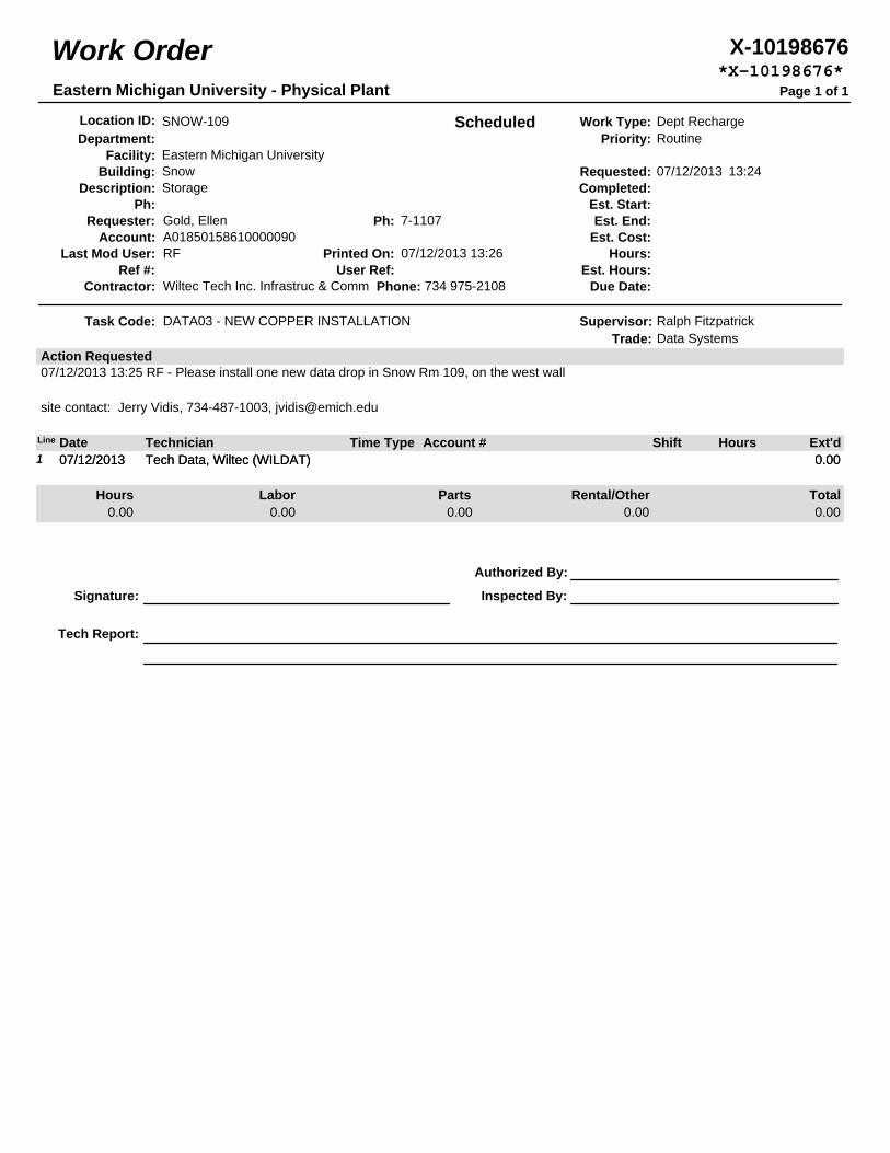
Work Order X-10198676*X-10198676*
Eastern Michigan University - Physical Plant Page 1 of 1
Location ID: SNOW-109 Scheduled Work Type: Dept RechargeDepartment: Priority: Routine
Facility: Eastern Michigan UniversityBuilding: Snow Requested: 07/12/2013 13:24
Description: Storage Completed:Ph: Est. Start:
Requester: Gold, Ellen Ph: 7-1107 Est. End:Account: A01850158610000090 Est. Cost:
Last Mod User: RF Printed On: 07/12/2013 13:26 Hours:Ref #: User Ref: Est. Hours:
Contractor: Wiltec Tech Inc. Infrastruc & Comm Phone: 734 975-2108 Due Date:
Task Code: DATA03 - NEW COPPER INSTALLATION Supervisor: Ralph FitzpatrickTrade: Data Systems
Action Requested07/12/2013 13:25 RF - Please install one new data drop in Snow Rm 109, on the west wall
site contact: Jerry Vidis, 734-487-1003, [email protected]
Line Date Technician Time Type Account # Shift Hours Ext'd1 07/12/2013 Tech Data, Wiltec (WILDAT) 0.001 07/12/2013 Tech Data, Wiltec (WILDAT) 0.00
Hours Labor Parts Rental/Other Total0.00 0.00 0.00 0.00 0.00
Authorized By:
Signature: Inspected By:
Tech Report:
Eastern Michigan University DiClemente Siegel Design Inc. Division of Information Technology DSD Project No. 13-0504.00 Information Technology Specifications v2.0
COMMUNICATIONS CABINETS, RACKS, FRAMES & ENCLOSURES 271116 - 1
SECTION 271116 – COMMUNICATIONS CABINETS, RACKS, FRAMES & ENCLOSURES
PART 1 - GENERAL
1.1 RELATED DOCUMENTS
A. Drawings and general provisions of the Contract, including General and Supplementary Conditions and Division 01 Specification Sections, apply to this section where project applicable.
A. Section 270000 – Communications General
B. Section 270500 – Common Work Results for Communications
C. Section 271119 – Communications Backbone Termination Hardware
D. Section 271120 – Communications Horizontal Termination Hardware
E. Section 271123 – Communications Cable Management & Runway
F. Section 271313 – Communications Copper Backbone Cabling
G. Section 271323 – Communications Optical Fiber Backbone Cabling
H. Section 271513 – Communications Horizontal Cabling
I. Section 271619 – Communications Patch Cords, Stations Cords and Cross-Connect Wires
1.2 CODES AND STANDARDS
A. Refer to Section 270000 – Communications General
B. Refer to Division 01, where project applicable.
1.3 DEFINITIONS
A. Refer to Section 270000 – Communications General
1.4 ACRONYMS & ABBREVIATIONS
A. Refer to Section 270000 – Communications General
1.5 SYSTEM DESCRIPTION
A. The predominant rack type(s) to be furnished and installed in support of EMU information transport systems shall be as follows: 1. Single upright, two-post Open Frame Rack Style
B. Specialty rack type(s) to be furnished and installed shall be as follows. Not all projects require such installations. Refer to Project Drawings for specifics and requirements. 1. Floor mount, four-post Open Frame Equipment Rack Style 2. Wall Mount, Open Frame Rack Style
Eastern Michigan University DiClemente Siegel Design Inc. Division of Information Technology DSD Project No. 13-0504.00 Information Technology Specifications v2.0
COMMUNICATIONS CABINETS, RACKS, FRAMES & ENCLOSURES 271116 - 2
3. Wall Mount Cabinets 4. Floor Mount Cabinets
C. Open frame equipment racks, 19 inches wide x 84 inches high, shall be furnished and installed such that rear access is available for installation and maintenance. Racks shall be bolted to the floor. The tops of the racks shall be securely braced to cable runway and bracketed to the wall. All hardware shall be provided for protection within seismic zones, where applicable.
D. Unequal flange equipment racks, 28 inches wide x 86 inches high, shall be furnished and installed such that rear access is available for installation and maintenance. Racks shall be bolted to the floor. The tops of the racks shall be securely braced to rigid cable runway and bracketed to the wall. All hardware shall be provided for protection within seismic zones, where applicable.
E. Contractors shall observe minimum clearance requirements as follows, unless otherwise directed by more specific or contingency arrangements provided in the Project Drawings. 1. Racks shall be mounted to allow a minimum of 36" access space in both front and rear. 2. The sides of a rack or group of racks situated against a wall shall have a minimum of 6"
clearance from rack to the adjacent wall, with 12” preferred where TR space allows. Clearance for the access “walk around” end shall be 24” at minimum.
F. Cabinets may be used occasionally for special purpose installations such as open area TRs, server systems, A/V systems, and CATV headend equipment. Open area TR cabinets are specified herein. For server systems, A/V systems, and CATV headend equipment, cabinets shall be specified as part of the system requirements contained within each individual systems specification (provided by others). In all cases, cabinets shall be installed according to practices contained within Section 271116.
1.6 QUALITY ASSURANCE
A. All cable and equipment shall be installed in a neat and workmanlike manner. All methods of construction that are not specifically described or indicated in the contract documents shall be subject to the control and approval of the Owner or Owner Representative. Equipment and materials shall be of the quality and manufacture indicated. The equipment specified is based upon the acceptable manufacturers listed. Where “approved equal” is stated, equipment shall be equivalent in every way to that of the equipment specified and subject to approval.
B. Strictly adhere to all Building Industry Consulting Service International (BICSI), Electronic Industries Alliance (EIA) and Telecommunications Industry Association (TIA) recommended installation practices when installing communications/data cabling.
1.7 SUBMITTALS
A. Refer to Section 270000 – Communications General
B. Environmental Requirements for Projects wherein active components are to be furnished and installed by Division 27: Technical submittals shall confirm the environmental specifications for physical ER/TR areas to be occupied. These environmental specifications shall identify the requirements for initial and expanded system configurations for: 1. Minimum floor space and ceiling heights. 2. Minimum size of doors for equipment passage. 3. Rack and floor loading for UPS cabinets and batteries. 4. Power requirements: The Contractor shall confirm the specific voltage, amperage,
phases, and quantities of circuits required.

Eastern Michigan University DiClemente Siegel Design Inc. Division of Information Technology DSD Project No. 13-0504.00 Information Technology Specifications v2.0
COMMUNICATIONS CABINETS, RACKS, FRAMES & ENCLOSURES 271116 - 3
5. Air conditioning, heating, and humidity requirements. The Contractor shall identify the ambient temperature and relative humidity operating ranges required to prevent damage.
6. Air conditioning requirements, expressed in BTU per hour, based on adequate dissipation of generated heat to maintain required room and equipment standards.
7. Proposed enlarged floor plan, based on the expanded system configuration of the Bidder's proposed equipment arrangement.
1.8 MATERIALS FOR USE BY OWNER
A. Furnish materials to EMU DoIT as described below: 1. All rack screws in excess of those required to install panels and devices shown in Project
Drawings. Refer to Part 2 Products. 2. All panels in excess of those required to install panels and devices shown in Project
Drawings. Refer to Part 2 Products.
B. Throughout installation, materials shall be securely stored at the project site. When called for by the Owner, materials shall be delivered by the Contractor who shall obtain a signature of acceptance and delivery from EMU DoIT.
PART 2 - PRODUCTS
2.1 BASIS OF DESIGN AND REFERENCE PART NUMBERS
A. Bidder shall confirm all reference part numbers, listed within Division 27, as current and suitable for the items described and specified and shall file a formal RFI for all perceived discrepancies prior to bidding.
B. Refer to Section 270000 Communications General, Part 2.
2.2 APPROVED MANUFACTURERS
A. Products by the following manufacturers shall be considered equal where applied to the Basis of Design and Reference Part Number listed within this section. 1. Hubbell or approved equal. 2. Chatsworth Products, Inc. or approved equal 3. Cooper/B-Line or approved equal 4. Hoffman or approved equal 5. EMU approved equal, documented by a pre-bid addendum
2.3 OPEN FRAME EQUIPMENT RACKS – SINGLE UPRIGHT, 2-POST
A. Racks shall be manufactured from aluminum.
B. Each rack shall have two (2) L-shaped top angles, two (2) L-shaped base angles and two (2) C-shaped equipment-mounting channels. The rack shall assemble with bolt hardware. Equipment-mounting channels shall be threaded for easy assembly. The base angles shall be pre-punched for attachment to the floor.
C. Equipment mounting channels shall be 3” deep and punched on the front and rear flange with the EIA-310-D universal hole pattern to provide forty-five (45) rack-mount spaces for equipment. Each mounting space shall be marked and numbered on the mounting channel.
Eastern Michigan University DiClemente Siegel Design Inc. Division of Information Technology DSD Project No. 13-0504.00 Information Technology Specifications v2.0
COMMUNICATIONS CABINETS, RACKS, FRAMES & ENCLOSURES 271116 - 4
D. When assembled with top and bottom angles, equipment-mounting channels shall be spaced to allow attachment of 19” EIA rack-mount equipment. Attachment points shall be threaded with 12-24 roll-formed threads. The rack shall include assembly and equipment-mounting hardware. Each rack shall include fifty (50) each combination pan head, pilot point mounting screws.
E. The assembled rack shall measure 7’ (84”) high x 20.3” wide x 15” deep. The sides (webs) of the equipment-mounting channels shall be punched to allow attachment of vertical cable managers along the sides of the rack or for rack-to-rack baying.
F. The rack shall be rated for 1,000 lb. of equipment.
G. The rack shall be UL Listed.
H. Finish shall be epoxy-polyester hybrid powder coat, black in color.
I. Furnish and install all necessary hardware for mounting equipment racks. Racks shall be securely mounted at both top and bottom. If this is not possible for any reason, EMU DoIT shall be notified immediately.
J. Furnish and install all necessary hardware for mounting, grounding, and bonding of equipment in equipment racks as per the Panduit Structured Ground™ System. Refer to Section 270500 – Common Work Results for Communications.
2.4 FLOOR MOUNT, 4-POST - OPEN FRAME EQUIPMENT RACK STYLE
A. Rack shall have a rectangular frame. Installed racks shall include power, and cable management accessories that keep network and power cables separate and organized.
B. The rack frame shall be rectangular with four corner posts, manufactured from steel with welded and bolted frame construction. The front and are rear of the cabinet shall be welded rectangular frames. The sides of the cabinet shall have three steel supports located near the top, middle and bottom to allow attachment of equipment mounting rails and thermal, cable and power management accessories. The side supports shall be bolted to the front and rear frames.
C. The rack frame shall include leveling feet. The rack frame shall support 3000 lb (1360 kg) of equipment when supported on leveling feet and secured to the structural floor.
D. Each rack shall include (2) two pairs of equipment mounting rails. Mounting rails shall clamp to the side supports located near the top, middle and bottom of the frame and shall be fully adjustable in depth to provide front and rear support for equipment. Equipment Mounting Rails shall be spaced horizontally to support 19” wide EIA-310 compliant rack-mount equipment.
E. The mounting rails shall be electrically bonded to the cabinet frame. The rack frame shall have a prepared location for attaching a grounding lug.
F. The cabinet shall be UL Listed as an Information Technology and Communications Equipment Cabinet, Enclosure and Rack System to standard UL 60950 under category NWIN. UL Listing will be stated in the manufacturer’s product literature.
G. The rack frame and mounting rails shall be black. Plastic components shall be black.
H. Each installed cabinet shall be equipped with a vertical cable manager to organize network cables. The vertical cable manager shall attach to the side of the equipment mounting rail. The vertical cable manager shall have cable openings along the side that align with each rack-mount

Eastern Michigan University DiClemente Siegel Design Inc. Division of Information Technology DSD Project No. 13-0504.00 Information Technology Specifications v2.0
COMMUNICATIONS CABINETS, RACKS, FRAMES & ENCLOSURES 271116 - 5
unit (U) space on the mounting rail. The openings shall be sized to allow 24 patch cords to enter each rack-mount unit (U) space. The cable openings shall be separated by plastic T-shaped cable guides to route cables into each space.
I. Provide additional equipment mounting hardware to attach equipment to the equipment mounting rails in the cabinet.
J. Provide a ground terminal block for connecting the cabinet to the Telecommunications Ground. The ground terminal block shall be made of a conductive material, have a mounting hole sized for M6 hardware and attachment points for two conductors of various size up to #4 AWG.
K. Provide hardware for attaching cable runway (ladder rack) to the top of the rack. The hardware shall attach the ladder rack in parallel (side-to-side) orientation and will elevate the ladder rack a minimum of 4” above the rack.
L. Provide (4) 3/8” or M10 anchors and hardware for securing the rack to the structural floor.
2.5 OPEN FRAME EQUIPMENT RACKS – HEAVY DUTY WALL MOUNTED
A. Wall-mounted racks shall be manufactured from sheet aluminum and aluminum extrusion.
B. Rack shall support 19” EIA or 23” wide equipment, as shown in Project Drawings.
C. Rack shall be EIA-310-D compliant. Rack-mount spaces/units (RMU) shall be 1-3/4” high. The rack shall have a single pair of C-shaped equipment mounting rails. The front and back of the mounting rails shall be punched with the Universal hole pattern. Mounting holes shall be spaced vertically on alternating 5/8”-5/8”-1/2” centers and shall be roll-formed with #12-24 threads. Mounting rails shall provide twenty (20) or forty (40) rack-mount spaces (RMU) for equipment.
D. The rack shall be 18” or 24” deep as shown in Project Drawings.
E. The rack shall be rated to support 350 pounds of equipment. Load bearing capacity shall be stated in the manufacturer’s product literature.
F. Finish shall be epoxy-polyester hybrid powder coat (paint) black in color.
G. Each rack shall include fifty (50) each #12-24 equipment mounting screws and installation hardware.
2.6 CABINETS – WALL MOUNTED
A. Wall mounted cabinets shall be manufactured from steel sheet.
B. Each cabinet shall have a rear panel that attaches to the wall, a hinged cabinet body that swings open from the rear panel providing easy access to the rear of equipment and a locking front door.
C. The rear panel shall be 5” deep and shall provide cable access with pre-punched knockouts for conduit along the top and bottom edges of the panel. There shall be a minimum of four (4) combination 1/2” and 3/4” conduit knockouts (2 top/2 bottom) and eight (8) combination 2-1/2” and 3” knockouts (4 top/4 bottom). The back edge of the knockouts shall be located 1-5/8” from the back surface of the panel (cabinet/wall) allowing conduit to be attached to the wall with auxiliary framing strut. The cabinet shall include rubberized or plastic/composite grommets that fit within the 3” knockouts to protect cables when conduit is not used to route cables. There shall
Eastern Michigan University DiClemente Siegel Design Inc. Division of Information Technology DSD Project No. 13-0504.00 Information Technology Specifications v2.0
COMMUNICATIONS CABINETS, RACKS, FRAMES & ENCLOSURES 271116 - 6
also be cutouts in the back of the rear panel so that cables can enter the panel through the wall. The rear panel shall provide attachment points for accessory equipment mounting brackets and cable tie points within the panel (cabinet).
D. The cabinet body shall include a single pair of vertical 19” EIA equipment mounting rails. The mounting rails shall be EIA-310-D compliant with the Universal hole pattern. Mounting holes shall be spaced vertically on alternating 5/8”-5/8”-1/2” centers and shall be roll-formed with #12-24 threads. Mounting rails shall provide 12, 18, 26, 33 or 40 rack-mount spaces (RMU) for equipment as per Project Drawings.
E. Mounting rails shall be adjustable in depth so that they can be positioned at any point within the cabinet body. The design of all cabinets shall allow an additional pair of mounting rails (for a total of two (2) pairs of mounting rails per cabinet) to be added to the cabinet.
F. The cabinet shall be available in two (2) styles: wall-mount only and wall-mount and floor-supported with a wheeled base. Cabinets that provide 12, 18 or 26 rack-mount spaces [RMU] shall be wall-mount only. Cabinets that provide 33 or 40 rack-mount spaces [RMU] shall be wall-mount and floor-supported with a wheeled base.
G. In cabinets that are wall-mount only, mounting rails shall bolt in place directly to the cabinet frame. The mounting rails shall be L-shaped. The side of the mounting rails shall be punched to provide lacing points for cables.
H. In cabinets that are floor-supported with a wheeled base, mounting rails shall attach to extruded-aluminum supports that allow the mounting rails to be adjusted in depth without being removed from the cabinet frame. Supports shall attach to the cabinet frame near the top and bottom on both sides of the cabinet and shall go from the front of the cabinet body to the rear of the cabinet body. Each support shall include a numbered scale to allow easy depth and vertical alignment of mounting rails. The mounting rails shall be C-shaped, 3” deep and punched/threaded on both the front and rear flanges. Each equipment-mounting space (RMU) on the mounting rail shall be marked and numbered.
I. In cabinets that are floor-supported with a wheeled base, the design of the cabinet shall allow a minimum of one vertical cable manager and one vertical power strip to be attached on each side of the cabinet body outside of the rack-mount space. The cabinet shall be wider than 24” to provide a minimum of 3” of cable management space along both sides of the cabinet/internal rack-mount space. The manufacturer of the cabinet shall sell compatible vertical cable managers and compatible vertical power strips as separate accessories.
J. In cabinets that wall-mount only, the hinge design that attaches the cabinet body and the rear panel shall allow the rear panel to be removed during installation.
K. For all cabinets, the hinge that attaches the cabinet body and the rear panel shall allow the cabinet body to open at least 90°. The hasp used to secure the rear panel and the cabinet body together shall assist in drawing the components together during the locking action.
L. The cabinet body shall include vents that are designed to accept fan kits.
M. The front door shall be hinged and locking. The front door and rear panel shall be keyed alike. The front door shall have rounded edges and corners. The cabinet body shall allow the front door to be attached so that it shall swing open from the right or left. The front door shall be solid or have a tinted window, as specified below.
Eastern Michigan University DiClemente Siegel Design Inc. Division of Information Technology DSD Project No. 13-0504.00 Information Technology Specifications v2.0
COMMUNICATIONS CABINETS, RACKS, FRAMES & ENCLOSURES 271116 - 7
N. Finish shall be epoxy-polyester hybrid powder coat (paint) black in color. Mounting rail supports in cabinets that are floor-supported with a wheeled base are anodized aluminum. Tinted windows in doors shall be bronze acrylic (not clear) with a UL flammability classification of 94HB or better.
O. The cabinet shall be delivered fully assembled and shall include installation hardware (hex lag screws) for wood studs and fifty (50) each #12-24 equipment mounting screws.
P. Load bearing capacity for cabinets that wall-mount only shall be two-hundred (200) pounds per cabinet. Load bearing capacity for cabinets that are floor-supported with a wheeled base shall be 1,000 pounds per cabinet. Load bearing capacity shall be stated in the manufacturer’s product literature.
Q. Cabinets that are wall-mount only shall be certified and UL Listed to standard UL 60950 under category NWIN. UL Listing shall be stated in the manufacturer’s product literature.
R. Each Cabinet assembly shall include a Filter Fan Kit, and 8-Outlet Surge Protector Power Strip.
2.7 CABINET – FLOOR MOUNT
A. Cabinet enclosure shall have a rectangular frame and removable top panel, side panels and doors. Installed cabinets shall include thermal, power, and cable management accessories that control airflow through the cabinet and keep network and power cables separate and organized.
B. The cabinet frame shall be rectangular with four corner posts, manufactured from steel with welded and bolted frame construction. The front and are rear of the cabinet shall be welded rectangular frames. The sides of the cabinet shall have three steel supports located near the top, middle and bottom to allow attachment of equipment mounting rails and thermal, cable and power management accessories. The side supports shall be bolted to the front and rear frames.
C. The cabinet frame shall include leveling feet. The cabinet frame shall support 3000 lb (1360 kg) of equipment when supported on leveling feet and secured to the structural floor.
D. Each cabinet shall include (2) two pairs of equipment mounting rails. Mounting rails shall clamp to the side supports located near the top, middle and bottom of the frame and shall be fully adjustable in depth to provide front and rear support for equipment. Equipment Mounting Rails shall be spaced horizontally to support 19” wide EIA-310 compliant rack-mount equipment.
E. The cabinet shall include a solid top panel with four multi-sized cable knockouts/ports, one in each corner.
F. Each installed cabinet shall include a fan top panel kit to help remove hot air from the cabinet. The fan top panel kit shall include four 100 CFM (170 CMH) fans in two housings attached to a solid cabinet top panel with vented center section and cable knockouts in each corner. Fans will be rated for 115 VAC, 50-60 Hz. The fan kit shall include a single detachable 15’ long power cord with dual IEC 60320 C13 power connectors (1 per fan housing) and a NEMA L5-15P plug.
G. Each installed cabinet shall be equipped with a bottom panel to block airflow through the bottom of the cabinet.
H. The cabinet shall include two half-height, solid side panels. Each side panel shall have a keyed latch located at the top center of the panel for easy installation and removal.
Eastern Michigan University DiClemente Siegel Design Inc. Division of Information Technology DSD Project No. 13-0504.00 Information Technology Specifications v2.0
COMMUNICATIONS CABINETS, RACKS, FRAMES & ENCLOSURES 271116 - 8
I. The cabinet shall include a single curved perforated metal front door with quick-release hinge pins. The primary door panel shall be constructed using a single perforated sheet (63% open) with a solid outer perimeter. The door assembly shall include upper and lower metal caps that follow the curved contour of the primary door panel. The door shall be removable and reversible to open from the right or left. The front door shall have a swing handle with a single-point cam latch and a keyed lock.
J. The cabinet shall include a double (vertically split) perforated metal rear door with quick-release hinge pins. Each door panel shall be constructed using a single perforated sheet (63% open) with a solid outer perimeter. The doors shall be removable. The double rear door shall have a swing handle with a two-point latch and a keyed lock.
K. The mounting rails, top panel, side panels and doors shall be electrically bonded to the cabinet frame. The cabinet frame shall have a prepared location for attaching a grounding lug.
L. The cabinet shall be UL Listed as an Information Technology and Communications Equipment Cabinet, Enclosure and Rack System to standard UL 60950 under category NWIN. UL Listing will be stated in the manufacturer’s product literature.
M. The cabinet frame, top panel, side panels, mounting rails and doors shall be painted black with epoxy-polyester hybrid powder coat paint. Plastic components shall be black.
N. Each installed cabinet shall be equipped with a vertical cable manager to organize network cables. The vertical cable manager shall attach to the side of the equipment mounting rail in the cabinet. The vertical cable manager shall have cable openings along the side that align with each rack-mount unit (U) space on the mounting rail. The openings shall be sized to allow 24 patch cords to enter each rack-mount unit (U) space. The cable openings shall be separated by plastic T-shaped cable guides to route cables into each space.
O. Provide additional equipment mounting hardware to attach equipment to the equipment mounting rails in the cabinet.
P. Provide a ground terminal block for connecting the cabinet to the Telecommunications Ground. The ground terminal block shall be made of a conductive material, have a mounting hole sized for M6 hardware and attachment points for two conductors of various size up to #4 AWG.
Q. Provide hardware for attaching cable runway (ladder rack) to the top of the cabinet. The hardware shall attach the ladder rack in parallel (side-to-side) orientation and will elevate the ladder rack a minimum of 2” above the cabinet.
R. Provide (4) 3/8” or M10 anchors and hardware for securing the cabinet to the structural floor.
PART 3 - EXECUTION
3.1 GENERAL
A. Examine all elements intended for Communications. Check pathways, raceways, cable trays, and other elements for compliance with space allocations, installation tolerances, installation hazards or impediments, and other conditions affecting installation. Verify that all work required in the field is adequately described in the plans. Proceed with installation only after unsatisfactory conditions and discrepancies have been brought to the attention of the Project Manager and corrected.
Eastern Michigan University DiClemente Siegel Design Inc. Division of Information Technology DSD Project No. 13-0504.00 Information Technology Specifications v2.0
COMMUNICATIONS CABINETS, RACKS, FRAMES & ENCLOSURES 271116 - 9
3.2 EQUIPMENT INSTALLATION
A. General
1. Each enclosure shall be floor or wall mounted with standard knockout holes for conduit connections or cable entrance; provide for ventilation of the equipment; have front and rear locking doors (except wall mounted cabinets that require only a front locking door); power outlet strip(s), and connector or patch panel(s).
2. Rack rails mounted equipment shall be installed in the enclosure’s equipment adjustable mounting racks with equipment normally requiring adjustment or observation mounted so operational adjustment(s) can be conveniently made. Heavy equipment shall be mounted with rack slides or rails allowing servicing from the front of the enclosure. Heavy equipment shall not depend only upon front panel mounting screws for support. Equipment shall be provided with sufficient cable slack to permit servicing by removal of the installed equipment from the front of the enclosure. A color matched blank panel (spacer) of 44 mm (1.75 in.) high, shall be installed between each piece of equipment (active or passive) to insure adequate air circulation. The enclosure shall be designed for efficient equipment cooling and air ventilation. Each console or cabinet shall be equipped with a quiet fan and non-disposable air filter.
3. Enclosures and racks shall be installed plumb and square. Each shall be permanently attached to the building structure and held firmly in place.
4. Equipment located indoors shall be installed in metal racks to allow access for maintenance without causing interference to other nearby equipment.
5. Cables shall enter the equipment racks in such a manner that allows all doors or access panels to open and close without disturbing or damaging the cables.
6. All distribution hardware shall be securely mounted in a manner that allows access to the connections for testing and provides sufficient room for the doors or access panels to open and close without disturbing the cables.
B. Open Frame Equipment Racks – Single Upright, 2-Post
1. Assemble racks according to manufacturer’s instructions. Verify that equipment mounting rails are sized properly for rack-mount equipment before attaching the rack to the floor.
2. All racks shall be attached to the floor in four places using appropriate floor mounting anchors. When placed over a raised floor, threaded rods should pass through the raised floor tile and be secured in the structural floor below. (Use CPI raised floor rack support kit; selection per EMU existing raised floor specifications.)
3. All Racks shall be individually (home-run) grounded to the TGB or TMGB using appropriate hardware provided by the Electrical Contractor. The ground shall meet local code requirements and shall be approved by the Authority Having Jurisdiction (AHJ). Refer to Section 270500 – Common Work Results for Communications.
4. Racks shall have additional bracing as required for by building codes and the recommendations of a licensed Structural Engineer for seismic.
5. Runway rack shall be attached 6” from the top of the rack to deliver cables to the rack using appropriate radius control “waterfall” kits. The rack should not be drilled to attach Cable Runway. Use appropriate hardware from the cable runway manufacturer. Refer to Section 271123 – Communications Cable Management & Runway.
6. Communications Cable Management shall be attached to the sides of the rack to deliver cables to the rack. The rack should not be drilled to attach cable management. Use appropriate hardware from the cable management manufacturer. Refer to Section 271123 – Communications Cable Management & Runway.
7. All active equipment shall be placed within the racks by EMU DoIT.
Eastern Michigan University DiClemente Siegel Design Inc. Division of Information Technology DSD Project No. 13-0504.00 Information Technology Specifications v2.0
COMMUNICATIONS CABINETS, RACKS, FRAMES & ENCLOSURES 271116 - 10
C. Open Frame Equipment Racks – Heavy Duty Wall Mounted 1. Follow the manufacturer’s assembly and installation instructions when securing the rack
to the wall. The rack should be installed on a plywood backboard or attached to a masonry wall. The rack shall not be attached to sheet rock (gypsum wall board).
D. Cabinets – Wall Mounted 1. Furnish and install all components of the cabinet system (cabinet, mounting rails, cable
managers, power strips, and accessories) from a single manufacturer. 2. Attach the cabinet to the wall so that the front door and cabinet body can be opened fully
without obstruction by other building, storage or architectural components. Follow the manufacturer’s installation instructions when securing the cabinet to the wall and backboard. The wheeled base on floor-supported cabinets must contact the floor. The wheeled base should not be removed and omitted from the installation. When not attached to the wall, the floor, shelf or tabletop surface on which the cabinet is placed must be able to hold the combined weight of the cabinet and the equipment within the cabinet. The cabinet shall not be attached to sheet rock (gypsum wall board). The cabinet shall be attached directly into masonry or studs through a 3/4” plywood backboard. The cabinet may be attached to a masonry wall when the installer provides hardware. Use included hardware or the appropriate hardware as defined by local code or the authority having jurisdiction. The top of the cabinet when installed should not exceed 84” above the finished floor.
3. Cables shall enter/exit the cabinet through conduit knockouts in the top and/or bottom of the rear panel of the cabinet or through the rectangular cut outs in the back of the rear panel of the cabinet. Use edge-protection grommets on conduit knockouts when cables pass through a conduit knockout but are not enclosed in conduit.
4. Install and adjust to position all accessories including vertical cable managers, power strips, equipment-mounting rails, fan and filter kits, lights, etc. prior to installing equipment into the cabinet. Verify that fans, light, power strip work prior to installing equipment. Shelves, if used, may be installed with equipment.
5. Furnish and install a telecommunications ground for equipment within the cabinet. Attach a 19” EIA bus bar to the equipment mounting rails so that the mounting rails are bonded together. Attach a bonding conductor sized as defined in J-STD-607-A and as defined by local code or the authority having jurisdiction between the Telecommunications Grounding Busbar and the 19” EIA bus bar within the cabinet using two-hole compression lugs to connect the bonding conductor to each busbar. The installer will furnish and install the 19” EIA bus bar, antioxidant compound, the bonding conductor and other necessary hardware required to make the connections between the cabinet and the Telecommunications Grounding Busbar.
E. Structured Grounding System – Refer to Section 270500 Common Work Results for Communications
1. Structured grounding system shall provide a low resistance, verifiable, dedicated path to a locally provided TGB for purposes of maintaining performance, protection, and network reliability.
2. All communications spaces including, but not limited to EF, DC shall require a structured grounding system to which all communications rack, cabinet, cable runway, wall frame, and equipment grounding shall be terminated.
3. Furnish and install equipment including, but not limited to: a. Copper Compression HTAP(s) b. Copper Compression Two-Hole Lugs c. Rack-Mounted Grounding Strips(s) d. Cabinet-mounted Front-to-Rail Jumper(s) e. Paint-piercing Bonding Screws and Studs f. Paint-piercing Grounding Washers
Eastern Michigan University DiClemente Siegel Design Inc. Division of Information Technology DSD Project No. 13-0504.00 Information Technology Specifications v2.0
COMMUNICATIONS CABINETS, RACKS, FRAMES & ENCLOSURES 271116 - 11
g. ESD (Electrostatic Discharge) Studs and Static Wrist Straps (on per rack or cabinet).
F. Conductors
1. Within each communications space EF, TR, ER, and any other information transport systems distribution space, the Contractor shall furnish and install an individual home-run of green insulated stranded 6AWG copper ground wire directly from the TGB or TMGB to each and every assembly as follows: a. Rack or Cabinet b. Runway Tray Assembly c. Wall and Rack Mounted Frame d. EMU DoIT furnished Network Electronics Unit e. Shielded Patch Panel f. Primary Protector g. Secondary Protector
2. Route conductors on short direct paths that have minimum resistive and inductive impedance as follows: a. Bonding conductors shall be routed with minimum bends or changes in direction b. Bonding connections shall be made directly to the points being bonded. c. Do not bend the grounding conductor wires into tight angles. Changes in direction
shall be of the widest radius possible. d. Unnecessary connections or splices in bonding conductors shall be avoided. When
absolutely necessary, use an approved connection and position it in an accessible location.
3. All open frame rack assemblies and cabinets for Network Systems shall require vertical rack grounding strips (RGS). Strips shall be mounted on the right hand rear side of the vertical rack rails for two-post assemblies and on the right hand rear side of the front post for four-post assemblies. These mounting arrangements apply both to racks based on UTP and F/UTP cabling. Contractor shall confirm details with EMU DoIT prior to proceeding with the installation.
3.3 LABELING
A. Labeling shall be furnished and installed by the Contractor according to details to be provided by EMU DoIT. Contractor shall make early contact with DoIT Engineer to obtain specific requirements for each project.
B. General: Mechanically printed, adhesive labels shall be used in all cases. Labels shall have a white background with black lettering. Brady ID Pro label tape is recommended for the riser and station jacket labels. Brother P-Touch labels are recommended for all other labels.
C. Rack Labels: Each rack shall contain a label bearing the building and DC designation, followed by a dash and letter designation, indicating which rack it is in sequence.
END OF SECTION 271116
271119 - COMMUNICATIONS BACKBONE TERMINATION HARDWARE
Eastern Michigan University DiClemente Siegel Design Inc. Division of Information Technology DSD Project No. 13-0504.00 Information Technology Specifications v2.0
COMMUNICATION BACKBONE TERMINATION HARDWARE 271119 - 1
SECTION 271119 – COMMUNICATIONS BACKBONE TERMINATION HARDWARE
PART 1 - GENERAL
1.1 RELATED DOCUMENTS
A. Drawings and general provisions of the Contract, including General and Supplementary Conditions and Division 01 Specification Sections, apply to this Section
B. Section 270000 – Communications General
C. Section 270500 – Common Work Results for Communications
D. Section 271113 – Communications Entrance Protection
E. Section 271116 – Communications Cabinets, Racks, Frames, & Enclosures
F. Section 271123 – Communications Cable Management & Runway
G. Section 271313 – Communications Copper Backbone Cabling
H. Section 271323 – Communications Optical Fiber Backbone Cabling
1.2 CODES AND STANDARDS
A. Refer to Section 270000 – Communications General
B. Refer to Division 01, where project applicable.
1.3 SUMMARY
A. This Section includes: 1. Connector Housings for Optical Backbone Cabling Systems 2. Splice Housings for Optical Backbone Cabling Systems 3. Splice Trays for Optical Backbone Cabling Systems 4. Termination Blocks for Copper Backbone/Riser Cabling Systems 5. Modular Splicing System for Copper Backbone/Riser Cabling Systems
1.4 DEFINITIONS
A. Refer to Section 270000 – Communications General
1.5 ACRONYMS & ABBREVIATIONS
A. Refer to Section 270000 – Communications General
1.6 SUBMITTALS
A. Refer to Section 270000 – Communications General
Eastern Michigan University DiClemente Siegel Design Inc. Division of Information Technology DSD Project No. 13-0504.00 Information Technology Specifications v2.0
COMMUNICATION BACKBONE TERMINATION HARDWARE 271119 - 2
PART 2 - PRODUCTS
2.1 APPROVED MANUFACTURERS
A. Products by the following manufacturers shall be considered equal where applied to the Basis of Design and Reference Part Number listed within this section. 1. Corning Cable Systems 2. Hubbell Premise Wiring 3. Panduit 4. EMU approved equal, documented by a pre-bid addendum.
2.2 BASIS OF DESIGN AND REFERENCE PART NUMBERS
A. Bidder shall confirm all reference part numbers, listed within Division 27, as current and suitable for the items described and specified and shall file a formal RFI for all perceived discrepancies prior to bidding.
B. Refer to Section 270000 Communications General, Part 2.
2.3 CONNECTOR HOUSINGS FOR OPTICAL FIBER BACKBONE CABLING
A. Connector Housings shall be rack mounted enclosures with front and rear removable doors, removable top, large front-mounted fiber guides, splice tray option, and integrated hinged optical jumper manager. 1. 144-port units shall accept up to twelve (12) Pigtail Modules, supporting a maximum of
one-hundred forty-four (144) LC style couplings in 4U rack space. 2. 48-port units shall accept up to four (4) Pigtail Modules, supporting a maximum of forty-
eight (48) LC style couplings in 2U rack space.
B. Each housing shall include a full complement of blank panels, labels, cable storage accessories, cable grounding hardware kits, optical fiber cable routing accessory kit, and splice tray brackets. Housing shall be black in color.
C. Connector Housings shall include duplex LC style coupler panels and connectors as required for the complement of multimode and single mode optical fiber elements, indicated on Project Drawings.
D. Multimode Pigtail Modules shall each contain six (6) LC style duplex adapters and shall be color coded according to the optical fiber type for which they are applied. Laser-optimized 50/125μm multimode shall be aqua in color.
E. Single Mode Pigtail Modules shall each contain six (6) LC style duplex adapters and shall be color coded according to the optical fiber type for which they are applied. 8.2/125μm single mode shall be blue in color.
2.4 SPLICE HOUSINGS FOR OPTICAL FIBER BACKBONE CABLING
A. Splice Housings shall be rack mounted enclosures with front and rear lockable doors, removable top and bottom, and sliding shelf.
B. Splice Housing shall accommodate up to fourteen (14) .04 in. Type 4S splice trays in 5U rack space.
C. Housing shall be black in color.
Eastern Michigan University DiClemente Siegel Design Inc. Division of Information Technology DSD Project No. 13-0504.00 Information Technology Specifications v2.0
COMMUNICATION BACKBONE TERMINATION HARDWARE 271119 - 3
2.5 SPLICE TRAYS
A. Type 4S for twelve (12) heat-shrink fusion splices including fusion splice protectors for quantity of elements indicated in Project Drawings.
2.6 TERMINATION BLOCKS FOR COPPER BACKBONE RISER/FEEDER CABLING
A. Termination Blocks shall be 5-pair connector clips rated for Category 5e performance, at minimum. 1. 100-pair 110-style termination blocks; frame mount without legs for ER applications 2. 50-pair 110-style termination blocks; wall mount with legs for TR applications. 3. 100-pair 110-style termination blocks; wall mount with legs for TR applications. 4. 300-pair 110-style termination blocks; wall mount with legs for TR applications.
B. Blocks shall include clear plastic label holders with protected label strips, colored white for first level riser/feeder terminations and brown for interbuilding (campus) terminations.
2.7 COPPER BACKBONE SPLICING- INTERBUILDING ONLY (OSP)
A. Modular IDC splicing system, available from 5- and 25-pair configurations, to splice 22 to 26 AWG conductors. No single pair splice connectors shall be used. Materials shall be manufactured of fire retardant plastic and available as either dry or filled for moisture protection.
B. Splice Case(s) for indoor splicing applications shall be non-filled, straight or butt-splice configurations, sized according to pair count requirements for the cabling configurations furnished and installed.
C. Splice Case(s) for outdoor splicing applications shall be filled re-enterable configurations, sized according to pair count requirements for the cabling configurations furnished and installed.
D. Selection shall be at the discretion of the Contractor, according to preferred tooling.
2.8 LABELING
A. Adhesive machine printed white background with black lettering in all cases.
B. ¼” Black on White – equals are permitted. Refer to “PART 3 – EXECUTION” for details.
PART 3 - EXECUTION
3.1 INSTALLATION
A. Contractor shall include a minimum of fifteen (15) foot single service loop, secured to the ER/TR backboard or cable runways prior to completing the run to the optical fiber distribution panel within the floor or wall mounted equipment rack or cabinet.
B. Contractor shall include a minimum of two (2) foot single service loop, secured within the optical fiber connector housing prior to completing termination at the connector panel.
C. All Panels shall be securely mounted in the rack with a minimum of four (4) rack screws located in the four (4) corners of each panel.
Eastern Michigan University DiClemente Siegel Design Inc. Division of Information Technology DSD Project No. 13-0504.00 Information Technology Specifications v2.0
COMMUNICATION BACKBONE TERMINATION HARDWARE 271119 - 4
D. All Panels shall be arranged in sequential order from top to bottom and left to right within racks and shall be labeled in alphanumeric order according to the EMU-approved labeling scheme.
E. Panels for shielded cabling, where applicable, shall be bonded and grounded to rack frames within which they are installed and terminated directly to the TGB (Telecommunications Grounding Busbar) within each ER/TR space.
F. Category 3/5/5e Riser/Feeder/OSP cables shall be terminated as required on 110 blocks separate from those used for Station Cable and shall be mounted on a floor mounted frame (ER) or plywood backboard (TR). Riser cable shall be routed from the overhead cable runway around the perimeter of the plywood using metal D-Rings. All cabling shall approach the point of termination from the bottom, entering in the bottom of the block. All cables shall be neatly organized and dressed (combed) using plastic tie wraps with metal reinforced locking tabs. Cable management hardware shall be furnished and installed by the Contractor to ensure that the installation is neatly organized and readily identifiable. Riser and Station cabling may be routed using the same metal D-Rings. Riser cable sheath shall be grounded to the TGB using #6AWG stranded copper ground wire with a green plastic sheath.
3.2 LABELING
A. Labeling shall be furnished and installed by the Contractor according to the details provided by EMU DoIT. Contractor shall make early contact with the DoIT Engineer to obtain the approved identifiers and any other special requirements for each project.
B. General: Mechanically printed, adhesive labels shall be used in all cases. Labels shall have a white background with black lettering. Brother P-Touch labels are recommended for all types of panel labels.
C. Fiber Optic Hardware: Each fiber-optic cabinet will contain a label in the upper left hand corner of the door, with followed by the two-digit number of the panel. The cabinet’s interior label strip will be as follows. For each column, a label containing the originating ER/TR and cabinet label (FTxx) separated by a slash, followed by the destination ER/TR and cabinet label (FTxx) followed by the element count for each coupler panel position.
END OF SECTION 271119

271120 - COMMUNICATIONS HORIZONTAL TERMINATION HARDWARE
Eastern Michigan University DiClemente Siegel Design Inc. Division of Information Technology DSD Project No. 13-0504.00 Information Technology Specifications v2.0
COMMUNICATIONS HORIZONTAL TERMINATION HARDWARE 271120 - 1
SECTION 271120 – COMMUNICATIONS HORIZONTAL TERMINATION HARDWARE
PART 1 - GENERAL
1.1 RELATED DOCUMENTS
A. Drawings and general provisions of the Contract, including General and Supplementary Conditions and Division 01 Specification Sections, apply to this Section
B. Section 270000 – Communications General
C. Section 270500 – Common Work Results for Communications
D. Section 271116 – Communications Cabinets, Racks, Frames, and Enclosures
E. Section 271123 – Communications Cable Management and Runway
F. Section 271513 – Communications Horizontal Cabling
G. Section 271543 – Communications Faceplates and Connectors
H. Section 271619 – Communications Patch Cords, Station Cords, and Cross-Connect Wires
1.2 CODES AND STANDARDS
A. Refer to Section 270000 – Communications General
B. Refer to Division 01, where project applicable.
1.3 SUMMARY OF WORK
A. This Section includes: 1. Patch Panels for Copper Horizontal Cabling Systems 2. Termination Blocks for Copper Horizontal Cabling Systems. 3. Connector Housings for Optical Fiber Horizontal Cabling Systems. Note that not all
projects include horizontal fiber. Refer to Project Drawings for all requirements.
B. Furnish and install new horizontal Category 6 “Data” Cabling from Telecommunications Rooms to WAO and TO locations as indicated on Plans. Furnish and install new cabling, faceplates, and jacks. Terminate, test, label, and document all locations.
C. Furnish and install new horizontal Category 6 “Voice and/or Telephone” Cabling from Telecommunications Rooms to WAO and TO locations as indicated on Plans. Furnish and install new cabling, faceplates, and jacks. Terminate, test, label, and document all locations.
1.4 DEFINITIONS
A. Refer to Section 270000 – Communications General
1.5 ACRONYMS & ABBREVIATIONS
A. Refer to Section 270000 – Communications General

Eastern Michigan University DiClemente Siegel Design Inc. Division of Information Technology DSD Project No. 13-0504.00 Information Technology Specifications v2.0
COMMUNICATIONS HORIZONTAL TERMINATION HARDWARE 271120 - 2
1.6 SUBMITTALS
A. Refer to Section 270000 – Communications General
PART 2 - PRODUCTS
2.1 APPROVED MANUFACTURERS
A. Products by the following manufacturers shall be considered equal where applied to the Basis of Design and Reference Part Number listed within this section. 1. Belden 2. Leviton 3. EMU approved equal, documented by a pre-bid addendum
2.2 BASIS OF DESIGN AND REFERENCE PART NUMBERS
A. Bidder shall confirm all reference part numbers, listed within Division 27, as current and suitable for the items described and specified and shall file a formal RFI for all perceived discrepancies prior to bidding.
B. Refer to Section 270000 Communications General, Part 2.
2.3 PATCH PANELS FOR COPPER HORIZONTAL CABLING
A. For ER, TR, and other information transport distribution spaces: 1. Provide 24-Port Category 6 UTP Patch Panels with insulation displacement connecting
blocks for termination of all horizontal channels. Insulation displacement connecting blocks shall be based on component-rated 110-style connector technology.
2. Patch Panels shall contain 8-position RJ-45 UTP ports that meet or exceed transmission performance of Category 6 for the horizontal system.
3. Patch Panels shall terminate four (4) pairs of Category 6 UTP horizontal cabling per port.
2.4 TERMINATION BLOCKS FOR COPPER HORIZONTAL CABLING
A. Termination Blocks shall be 4-pair connector clips rated for Category 6 performance, at minimum. 1. 100-pair 110-style termination blocks; wall mount with legs for TR applications.
B. Blocks shall include clear plastic label holders with protected label strips, colored white for horizontal terminations.
2.5 LABELING
A. Adhesive machine printed white background with black lettering in all cases.
B. ¼” Black on White – equals are permitted. Refer to “PART 3 – EXECUTION” for details.

Eastern Michigan University DiClemente Siegel Design Inc. Division of Information Technology DSD Project No. 13-0504.00 Information Technology Specifications v2.0
COMMUNICATIONS HORIZONTAL TERMINATION HARDWARE 271120 - 3
PART 3 - EXECUTION
3.1 INSTALLATION
A. All Panels shall be securely mounted in the rack with a minimum of four (4) rack screws located in the four (4) corners of each panel.
B. All Blocks shall be securely mounted to the wall panel or frame with a minimum of four (4) screws located in the four (4) corners of each block.
C. All Panels and Blocks shall be arranged in sequential order from top to bottom and left to right within racks and shall be labeled in alphanumeric order according to the OC-approved labeling scheme.
D. Panels for shielded cabling, where applicable, shall be bonded and grounded to rack frames within which they are installed and terminated directly to the TGB (Telecommunications Grounding Busbar) within each TR space.
E. Category 6 Station cables shall be terminated as required on 110 blocks separate from those used for Riser/Feeder/OSP Cable and shall be mounted on plywood backboard in the TR. Station cable shall be routed from the overhead cable runway around the perimeter of the plywood using metal D-Rings. All cabling shall approach the point of termination from the top, entering in the top of the block. All cables shall be neatly organized and dressed (combed) using plastic tie wraps with metal reinforced locking tabs. Cable management hardware shall be furnished and installed by the Contractor to ensure that the installation is neatly organized and readily identifiable. Station cabling shall be routed using metal D-Rings.
3.2 LABELING
A. Labeling shall be furnished and installed by the Contractor according to the details provided by the Owner. Contractor shall make early contact with the Owner to obtain the approved identifiers and any other special requirements for each project.
B. General: Mechanically printed, adhesive labels shall be used in all cases. Labels shall have a white background with black lettering. Brother P-Touch labels, or equal, are recommended for all types of panel labels.
END OF SECTION 271120
271123 - COMMUNICATIONS CABLE MANAGEMENT & RACEWAY
Eastern Michigan University DiClemente Siegel Design Inc. Division of Information Technology DSD Project No. 13-0504.00 Information Technology Specifications v2.0
COMMUNICATIONS CABLE MANAGEMENT AND RUNWAY 271123 - 1
SECTION 271123 – COMMUNICATIONS CABLE MANAGEMENT AND RUNWAY
PART 1 - GENERAL
1.1 RELATED DOCUMENTS
A. Drawings and general provisions of the Contract, including General and Supplementary Conditions and Division 01 Specification Sections, apply to this Section
A. Section 270000 – Communications General
B. Section 270500 – Common Work Results for Communications
C. Section 271113 – Communications Entrance Protection
D. Section 271116 – Communications Cabinets, Racks, Frames, & Enclosures
E. Section 271119 – Communications Backbone Termination Hardware
F. Section 271313 – Communications Copper Backbone Cabling
G. Section 271323 – Communications Optical Fiber Backbone Cabling
H. Section 271513 – Communications Horizontal Cabling
1.2 SUMMARY
A. Section Includes: 1. Vertical and Horizontal Cable Management 2. Cable Runway 3. Fiber Runner Channel System
1.3 CODES AND STANDARDS
A. Refer to Section 270000 – Communications General
B. Refer to Division 01, where project applicable.
1.4 DEFINITIONS
A. Refer to Section 270000 – Communications General
1.5 ACRONYMS & ABBREVIATIONS
A. Refer to Section 270000 – Communications General
1.6 SYSTEM DESCRIPTION
A. The predominant rack type(s) to be furnished and installed in support of EMU information transport systems shall be as follows: 1. Single upright, two-post Open Frame Rack Style
Eastern Michigan University DiClemente Siegel Design Inc. Division of Information Technology DSD Project No. 13-0504.00 Information Technology Specifications v2.0
COMMUNICATIONS CABLE MANAGEMENT AND RUNWAY 271123 - 2
B. Specialty rack type(s) to be furnished and installed shall be as follows. Not all projects require such installations. Refer to Project Drawings for specifics and requirements. 1. Floor mount, four-post Open Frame Equipment Rack Style 2. Wall Mount, Open Frame Rack Style 3. Wall Mount Cabinets 4. Floor Mount Cabinets
C. Vertical Cable Management sections, 84”H, shall be bolted-in between all Open Frame Racks. Width of Vertical Cable Management sections shall be as indicated on Project Drawings.
D. Vertical Slack Managers shall be bolted-in between all Unequal Flange Racks. Width of Vertical Slack Manager sections shall be as indicated on Project Drawings.
E. The work covered under this section consists of furnishing all necessary coordination, labor, supervision, materials, and services required to install complete Cable Runway systems within the DC space, as indicated within project Drawings.
1.7 QUALITY ASSURANCE
A. All cable and equipment shall be installed in a neat and workmanlike manner. All methods of construction that are not specifically described or indicated in the contract documents shall be subject to the control and approval of the Owner. Equipment and materials shall be of the quality and manufacture indicated. The equipment specified is based upon the acceptable manufacturers listed. Where “approved equal” is stated, equipment shall be equivalent in every way to that of the equipment specified and subject to approval.
B. Strictly adhere to all Building Industry Consulting Service International (BICSI), Electronic Industries Alliance (EIA) and Telecommunications Industry Association (TIA) recommended installation practices when installing communications/data cabling.
1.8 SUBMITTALS
A. Refer to Section 270000 – Communications General
PART 2 - PRODUCTS
2.1 APPROVED MANUFACTURERS
A. Products by the following manufacturers shall be considered equal where applied to the Basis of Design and Reference Part Number listed within this section. 1. Cooper/B-Line 2. CPI (Chatsworth Products Inc.) 3. Hoffman 4. EMU approved equal, documented by a pre-bid addendum
2.2 BASIS OF DESIGN AND REFERENCE PART NUMBERS
A. Bidder shall confirm all reference part numbers, listed within Division 27, as current and suitable for the items described and specified and shall file a formal RFI for all perceived discrepancies prior to bidding.
B. Refer to Section 270000 Communications General, Part 2.

Eastern Michigan University DiClemente Siegel Design Inc. Division of Information Technology DSD Project No. 13-0504.00 Information Technology Specifications v2.0
COMMUNICATIONS CABLE MANAGEMENT AND RUNWAY 271123 - 3
2.3 CABLE MANAGEMENT
A. Vertical Cable Management for Floor Mounted Racks/Frames
1. Every Rack/Frame shall have a minimum of one (1) Vertical Cable Manager furnished and installed between racks and at the end of multiple rack line-ups. The Vertical Cable Manager shall create a space for storing and organizing cables along the side of each Rack/Frame.
2. Vertical Cable Manager width shall be sized as indicated on Project Drawings. 3. A single Vertical Cable Manager shall be used in between bayed Racks/Frames if it is
sized to match cable requirements for both Racks/Frames. 4. Vertical Cable Manager shall match the height of the Rack/Frame to which it shall be
attached. 5. Vertical Cable Manager shall bolt to the side of Racks/Frames using factory-provided
hardware and mounting provisions. The manufacturer of the Vertical Cable Manager shall be by the same manufacturer as the Racks/Frames. Refer to Section 271116 – Communications Cabinets, Racks, Frames, & Enclosures.
6. The Vertical Cable Manager shall be a single-sided C-shaped trough with latches on the front side. The front and rear metal edges in between the latches shall be covered by plastic edge protectors to protect cables.
7. The Vertical Cable Manager shall be manufactured from sheet aluminum and plastic materials.
8. Finish shall be epoxy-polyester hybrid powder coat paint, black in color. Edge-protectors and latch hardware shall be black in color.
B. Horizontal Cable Management for Racks/Frames 1. Furnish and install Horizontal Cable Managers 19”W x 3.5”H (2RU) or 19”W x 1.75”H
where specifically indicated on Project Drawings. 2. The cable manager will be sized to match cabling requirements. Provide 1 RMU of
horizontal cable management for every 2 RMU of connectivity. Cables must be able to access the cable manager so that no ports are blocked by the cables.
3. The Horizontal Cable Manager will match the rack-mount width of the rack(s)/frame(s)/cabinet(s).
4. The Horizontal Cable Manager will attach to the front or rear of the rack/frame/cabinet with screws and will be sized to fit within standard EIA-310-D (1-3/4” high RMU) rack-mount spacing.
5. The Horizontal Cable Manager will be a single-sided C-shaped trough with a cover. The single-sided trough will have a slot or holes at the rear to facilitate front-to-rear cabling through the horizontal manager. The front of the cable manager will have T-shaped cable guides along the top and bottom surfaces of the cable manager. Evenly spaced cable openings in between the T-shaped cable guides will allow cables to enter/exit the cable manager into the rack-mount space. The openings will have rounded edges to protect cables. The cover will be removable, hinged to open up or down and will snap on to secure the cover in the closed position.
6. The Horizontal Cable Manager shall be manufactured from sheet aluminum and composite materials.
7. Finish shall be epoxy-polyester hybrid powder coat paint, black in color. Edge-protectors, T-shaped cable guides and latch hardware shall be black.
C. Cable Routing Troughs for Optical Fiber Cross-Connects 1. Furnish and install Cable Routing Troughs where specifically indicated on the Project
Drawings. 2. Toughs shall be used to route optical fiber jumpers in and around optical fiber connector
housings as follows: a. Upper Trough- 2 RU with 1.3” bend radius
Eastern Michigan University DiClemente Siegel Design Inc. Division of Information Technology DSD Project No. 13-0504.00 Information Technology Specifications v2.0
COMMUNICATIONS CABLE MANAGEMENT AND RUNWAY 271123 - 4
b. Standard Trough- 4 RU c. Lower Trough- 4 RU with 1.3” bend radius
3. All Troughs shall be black in color.
2.4 CABLE RUNWAY AND ACCESSORIES
A. Project Color: Finish shall be black in color for all greenfield or complete renovation sites. Confirm prior to material procurement.
B. Cable runway rack shall be manufactured from 3/8” wide by 1-1/2” high tubular steel with .065” wall thickness.
C. Cable Runway rack (side stringers) shall be 9’-11½ “ long. Cross members shall be welded in between stringers on 12” centers beginning 5-3/4” from one end so that there are 10 cross members per cable runway. There shall be 10-1/2” of open space in between each cross member.
D. Furnish and install 18 inch wide or 24 inch ladder style Cable Runway sections in each TR and information transport systems space as indicated on Project Drawings. Cable Runway shall be securely mounted 6” above the top of equipment racks using all necessary hardware.
E. Cable Runway Radius Drops shall be mounted to stringer and cross members using clevis pins, where cabling must turn down into tops of Vertical Cable Managers.
F. Channel Mounting Plates shall be 3”. Include associated mounting hardware.
G. Wall Mounting Angles shall include J-Bolts and associated mounting hardware.
H. Vertical Wall Brackets shall include all hardware for secure mounting to wall surface.
I. Cable Runway Foot shall include mounting hardware including anchor to floor or wall surface.
J. Butt Splice Kit shall be heavy duty, complete with jointing and bonding hardware.
K. Triangular Support Brackets shall include all hardware for secure mounting to wall surface.
L. Runway/Enclosure Junction Kits shall include joining and bonding hardware.
M. Cable Runway Elevation Kit shall be used, if required to transition between racks of unequal heights.
N. Cable Retaining Posts shall be installed to create a cable trough effect using ladder style runway. Posts shall be black in color.
O. Cable Runway Pathway Dividers shall be installed to separately route backbone cabling away from horizontal cabling bundles where entering the ER or TR and routed to destination racks(s).
P. Protective End Caps shall be black in color.
Q. Furnish and install all hardware as required to form a complete system, whether or not specifically listed herein. Examples of required miscellaneous hardware include, but are not limited to threaded rod, threaded rod cover, beam clamps, lock nuts, runway and ceiling support brackets, slip-on support brackets, vertical wall brackets, etc.
Eastern Michigan University DiClemente Siegel Design Inc. Division of Information Technology DSD Project No. 13-0504.00 Information Technology Specifications v2.0
COMMUNICATIONS CABLE MANAGEMENT AND RUNWAY 271123 - 5
2.5 OPTICAL FIBER RACEWAY AND ACCESORIES
A. The optical fiber cable raceway specified herein for routing, separating, and protecting fiber optic jumper cabling shall be the Fiber-Duct Routing System as manufactured by the Panduit Corporation. Systems of other manufacturers may be considered equal, if, in the opinion and the written approval of the Owner, they meet all the performance standards required and specified.
B. The raceway system shall be UL Listed and utilize material which exhibits flame resistant characteristics, tested in accordance with UL94.
C. The raceway base and hinged cover shall be available in 6’ lengths.
D. The raceway shall be a two-piece design with a base and hinged cover that incorporates integral high friction design to retain and inhibit cover movement. Shall be approximately 12” and 6” wide by 4” deep with an approximate wall thickness of 0.12”. Refer to Project Drawings for specifics.
E. The base and cover shall be manufactured of rigid PVC compound.
F. Couplers shall be used at each connection. Each connection of fitting to fitting, raceway to fitting, and raceway to raceway shall require a coupler. Couplers shall be supplied preassembled and shall be removable when needed.
G. A full complement of fittings must be available including but not limited to 45 degree and 90 degree flat, vertical inside and outside elbows, tee and cross fittings, reducers, end caps and all other components necessary to make the system complete and workable. The fittings shall be capable of maintaining a 2” minimum cable bend radius. The fittings shall be manufactured from ABS. All fitting base and covers shall be furnished and installed as separate components.
H. A full complement of mounting brackets shall be available including but not limited to new and existing threaded rod bracket kits, runway rack bracket kits, wall bracket kits and all other components necessary to make the system workable. The mounting brackets shall be manufactured from commercial grade cold rolled steel with zinc chromate finish or painted black power coat finish. The brackets shall attach to the raceway by securing to the rail on the bottom of the base.
I. All non-metallic components of the system and shall be yellow in color.
2.6 WARNING SIGNS
A. “Warning! Not To Be Used as Walkway, Ladder, or Support for Ladders or Personnel."
2.7 SOURCE QUALITY CONTROL
A. Testing: Test and inspect cable trays according to NEMA VE 1.
PART 3 - EXECUTION
3.1 GENERAL
A. Examine all elements intended for Communications. Check pathways, raceways, cable trays, and other elements for compliance with space allocations, installation tolerances, installation

Eastern Michigan University DiClemente Siegel Design Inc. Division of Information Technology DSD Project No. 13-0504.00 Information Technology Specifications v2.0
COMMUNICATIONS CABLE MANAGEMENT AND RUNWAY 271123 - 6
hazards or impediments, and other conditions affecting installation. Verify that all work required in the field is adequately described in the plans. Proceed with installation only after unsatisfactory conditions and discrepancies have been brought to the attention of the General Contractor and corrected.
3.2 EQUIPMENT INSTALLATION
A. VERTICAL CABLE MANAGEMENT 1. Vertical Cable Managers shall be attached to the side of the Rack/Frame using the
manufacturer’s installation instructions and included hardware. No holes shall be drilled in Racks/Frames in order to install mismatched managers.
2. When a single Vertical Cable Manager is used in between two Racks/Frames, attach the Vertical Cable Manager to both Racks/Frames.
3. When more than one (1) Vertical Cable Manager is used on a Rack/Frame or group of Racks/Frames, use the same make, style and size of Vertical Cable Manager on the Rack/Frame or in between Racks/Frames.
4. The color of the Racks/Frames and Vertical Cable Managers shall match.
B. HORIZONTAL CABLE MANAGEMENT
1. The Horizontal Cable Manager will attach to the front or rear of the rack/frame/cabinet with screws and will be sized to fit within standard EIA-310-D (1-3/4” high RMU) rack-mount spacing.
2. All Managers shall be securely mounted in the rack with a minimum of four (4) rack screws located in the four corners of each panel.
3. Place Horizontal Cable Managers above and below each patch panel on/in each rack/frame/cabinet. The Horizontal Cable Manager will guide patch/equipment cords between the vertical cable manager and individual network port connections.
4. A single Horizontal Cable Manager may be used to support multiple patch panels as long as it is sized to match cable fill requirements. Cables must be able to access the cable manager so that no ports are blocked by the cables.
C. CABLE RUNWAY
1. Cable runway shall be installed with side stringers facing down so that the runway forms an inverted U-shape and so that welds between the stringers (sides) and cross members (middle) face away from cables.
2. Cable runway shall be supported every 5 feet on center with 5/8 inch diameter threaded rod, or applicable support brackets or racks. Exposed portion of threaded rod shall be protected with tubular cover throughout the portion of the rod exposed to cabling within the maximum fill area.
3. Cable runway shall be secured to the structural ceiling, building truss system, wall, floor or the tops of equipment racks and/or cabinets using the manufacturer’s recommended supports and appropriate installation hardware and methods as defined by local code or the authority having jurisdiction (AHJ).
4. Cable runway splices shall be made in mid-span, not over a support, using the manufacturer’s recommended splice hardware.
5. Cable runway shall be supported every 5’ or less in accordance with TIA-569-B. Cable runway shall be supported within 2’ of every splice and within 2’ on both/all sides of every intersection. Support Cable Runway within 2’ on both sides of every change in elevation. Support Cable Runway every 2’ when attached vertically to a wall.
6. Heavy-duty splices are recommended for Cable Runway in excess of 18” width (18” wide Cable Runway). Heavy-duty splices are required for any splice formed in the vertical orientation including changes in elevation formed using vertical-to-horizontal 90° turns or

Eastern Michigan University DiClemente Siegel Design Inc. Division of Information Technology DSD Project No. 13-0504.00 Information Technology Specifications v2.0
COMMUNICATIONS CABLE MANAGEMENT AND RUNWAY 271123 - 7
horizontal-to-vertical 90° turns. Use heavy-duty splices to secure all overhead turns to the overhead horizontal pathway(s).
7. When the pathway is overhead, Cable Runway shall be installed with a minimum clearance of 12” above the Cable Runway. Leave a minimum of 12” in between Cable Runway and ceiling/building truss structure. Leave a minimum of 3” in between Cable Runway and the tops of equipment racks and/or cabinets. Multiple tiers of Cable Runway shall be installed with a minimum clearance of 12” in between each tier of Cable Runway. When located above an acoustical drop ceiling, leave a minimum of 3” clearance between the top of the drop ceiling tiles and the bottom of the Cable Runway.
8. When installed under a raised floor, Cable Runway shall be installed with a minimum 3” clearance between the top of the Cable Runway and the bottom of the floor tiles or floor system stringers, whichever is lower in elevation. Maintain a 3” clearance between Cable Runways wherever Cable Runways cross.
9. Within each ER and TR, Cable Runway should be bonded together, electrically continuous, and bonded to the TMGB and TGB, unless otherwise specifically noted in the Project Drawings. Cable runway and turns shall be bonded across each splice with a bonding kit. Cable runway shall be bonded to the TMGB and TGB using an approved ground lug on the Cable Runway and a minimum #6 grounding wire or as recommended by the AHJ. Remove paint from the Cable Runway where bonding/ground lugs contact the Cable Runway so that the lug shall contact bare metal. Use antioxidant joint compound in between the bare metal on the Cable Runway and ground lug. Use antioxidant joint compound in between the bus bar and the ground lug. Verify continuity through the bonds at splices and intersections between individual Cable Runway sections and turns and through the bond to the TMGB and TGB.
10. The combined weight of cables within the Cable Runway shall not exceed the stated load capacity of the Cable Runway as stated in the manufacturer’s product specifications or load/design tables.
11. Straps shall not be required when Cable Runway is equipped with cable retaining posts. 12. Add 8” high cable retaining posts to the open sides of Cable Runway as indicated in
Project Drawings. Cable fill within any Cable Runway should not exceed 6” in height. 13. When a single Cable Runway supports different types of cable media, the cable media
shall be separated within the pathway by cable spools that attach to the cross members on the Cable Runway.
14. Use a radius drop to guide cables wherever cable exits overhead Cable Runway to access a rack, cabinet or wall-mounted rack, cabinet or termination field. Furnish and install a moveable cross member also to attach and align the radius drop in between the welded cross members of a Cable Runway.
15. Cover the exposed ends of Cable Runway that do not terminate against a wall, the floor or the ceiling with end caps or an end closing kit.
16. Use auxiliary support brackets that attach to the side stringer of the Cable Runway to support interconnect cabling (patch cords, equipment cords, jumper cords) that is routed between racks using the Cable Runway. Auxiliary support brackets can be used to support other conductors that should be physically separated from cables within the Cable Runway as defined by local code or the authority having jurisdiction (AHJ).
17. Whenever possible, maintain a 2’ separation between Cable Runway used for communications cables and pathways for other utilities or building services.
18. The installer shall furnish and apply touch-up paint color-matched to the finish on the Cable Runway and shall correct any minor cosmetic damage (chips, small scratches, etc.) resulting from normal handling during the installation process prior to delivery to the EMU project site. If a component is cosmetically damaged to the extent that correction in the field is obvious against the factory finish, the component shall be replaced with a new component finished from the factory. If a component is physically damaged due to mishandling or modification during the installation process, it shall not be used as part of the Cable Runway system.
19. Install Cable Runway level and straight unless specifically notes on Project Drawings.
Eastern Michigan University DiClemente Siegel Design Inc. Division of Information Technology DSD Project No. 13-0504.00 Information Technology Specifications v2.0
COMMUNICATIONS CABLE MANAGEMENT AND RUNWAY 271123 - 8
20. Furnish and install seismic protection products for all Cable Runway hardware assemblies.
21. Alternate spacing runway arrangements shall be made for all Cable Runway extends above and parallel to ER and TR racks rows so that space above entry point into vertical wire managers remains clear and precise alignment of Cable Runway radius drops can be assured.
22. Cable runway type runway shall be capable of carrying a uniformly distributed load of 135 lbs./ft. on a five foot support span with a safety factor of 1.5 when supported as a simple span. Load and safety factors specified are applicable to both side rails and rung capacities.
D. FIBER RUNNER ROUTING SYSTEM
1. Coordinate the fiber routing system installation with all other work as necessary to properly interface installation of fiber routing pathway with cabinets, racks, etc. Sufficient space shall be provided in areas encompassing fiber routing system to allow future access for installing and maintaining cables.
2. All fiber routing channel shall be cut using a miter box and saw. Larger quantities shall be cut using a plastic cutting saw blade for clean, burr-free cuts. Recommended Carbide 80T or 100T; .090 thickness, .125” kerf.
3. Install the fiber routing system in accordance with recognized industry practices per UL 2024A. This will ensure that the system complies with requirements of UL / ULC standard that pertain to Optical Fiber Cable Routing Assemblies for Riser.
4. Fiber Routing channel, fittings, and accessories shall be delivered carefully to avoid breakage, bending and scratching finishes. Do not install damaged equipment.
5. Fiber Routing channel and accessories shall be stored in original packaging and in clean dry area. Product shall be protected from weather and construction traffic until installation.
3.3 FIELD QUALITY CONTROL
A. Perform the following tests and inspections:
1. After installing cable trays and after electrical circuitry has been energized, survey for compliance with requirements.
2. Visually inspect cable insulation for damage. Correct sharp corners, protuberances in cable trays, vibrations, and thermal expansion and contraction conditions, which may cause or have caused damage.
3. Verify that there are no intruding items such as pipes, hangers, or other equipment in the cable tray.
4. Remove dust deposits, industrial process materials, trash of any description, and any blockage of tray ventilation.
5. Visually inspect each cable tray joint and each ground connection for mechanical continuity. Check bolted connections between sections for corrosion. Clean and retorque in suspect areas.
6. Check to ensure that all bonding screws have been secured on all Splice Connectors. 7. Check for missing, incorrect, or damaged bolts, bolt heads, or nuts. When found, replace
with specified hardware. 8. Perform visual and mechanical checks for adequacy of cable tray grounding; verify that
all takeoff raceways are bonded to cable trays. Test entire cable tray system for continuity. Maximum allowable resistance is 1 ohm.
3.4 PROTECTION
A. Protect installed cable trays and cables.
Eastern Michigan University DiClemente Siegel Design Inc. Division of Information Technology DSD Project No. 13-0504.00 Information Technology Specifications v2.0
COMMUNICATIONS CABLE MANAGEMENT AND RUNWAY 271123 - 9
1. Install temporary protection for cables in open trays to safeguard exposed cables against falling objects or debris during construction. Temporary protection for cables and cable tray can be constructed of wood or metal materials and shall remain in place until the risk of damage is over.
END OF SECTION 271123
271313 - COMMUNICATIONS COPPER BACKBONE CABLING
Eastern Michigan University DiClemente Siegel Design Inc. Division of Information Technology DSD Project No. 13-0504.00 Information Technology Specifications v2.0
COMMUNICATIONS COPPER BACKBONE CABLING 271313 - 1
SECTION 271313 – COMMUNICATIONS COPPER BACKBONE CABLING
PART 1 - GENERAL
1.1 RELATED DOCUMENTS
A. Drawings and general provisions of the Contract, including General and Supplementary Conditions and Division 01 Specification Sections, apply to this Section
A. Section 270000 – Communications General
B. Section 270500 – Common Work Results for Communications
C. Section 271116 – Communications Cabinets, Racks, Frames, & Enclosures
D. Section 271119 – Communications Backbone Termination Hardware
E. Section 271123 – Communications Cable Management & Runway
F. Section 271323 – Communications Optical Fiber Backbone Cabling
1.2 CODES AND STANDARDS
A. Refer to Section 270000 – Communications General.
B. Refer to Division 01, where project applicable.
1.3 SYSTEM DESCRIPTION
A. The copper backbone hierarchy employed by EMU DoIT includes both Interbuilding and Intrabuilding cabling systems.
B. Intrabuilding deployment of copper shall be referred to as Backbone Riser or Feeder representing the digital voice telephony distribution system originating at the campus distributor or ER. The end destination of each interbuilding backbone link is a termination point within each TR (Telecommunications Room).
C. Interbuilding deployment of copper cabling systems shall be referred to as the Backbone OSP representing the digital voice telephony distribution system originating at the campus distributor or ER. Multi-pair counts shall be as specifically identified on Project Drawings. The end destination of each interbuilding backbone link is a termination point within each ER (Equipment Room) also referred to as EF (Entrance Facility) or SE (Service Entrance).
D. Multi-pair counts shall be as specifically identified on Project Drawings
1.4 DEFINITIONS
A. Refer to Section 270000 – Communications General
1.5 ACRONYMS & ABBREVIATIONS
A. Refer to Section 270000 – Communications General
Eastern Michigan University DiClemente Siegel Design Inc. Division of Information Technology DSD Project No. 13-0504.00 Information Technology Specifications v2.0
COMMUNICATIONS COPPER BACKBONE CABLING 271313 - 2
1.6 SUBMITTALS
A. Refer to Section 270000 – Communications General
B. After approval and prior to installation, furnish the Owner’s Representative with one (1) sample of each of the following: 1. One (1) 12 inch length of each type and size of wire and cable along with the tag from the
coils of reels or boxes from which the samples were taken.
PART 2 - PRODUCTS
2.1 APPROVED MANUFACTURERS 1. General Cable 2. Superior Essex 3. CommScope-Systimax 4. EMU approved equal, documented by a pre-bid addendum
2.2 BASIS OF DESIGN AND REFERENCE PART NUMBERS
A. Bidder shall confirm all reference part numbers, listed within Division 27, as current and suitable for the items described and specified and shall file a formal RFI for all perceived discrepancies prior to bidding.
B. Refer to Section 270000 Communications General, Part 2.
2.3 COPPER BACKBONE CABLING – INTRABUILDING (RISER/FEEDER)
A. Multi-pair copper backbone cables from the MC located in the ER shall be home-run routed directly to wall mounted termination blocks located in each TR.
B. Riser/Feeder Copper Backbone Cabling shall be ARMM construction, Category 3 performance rated multi-pair 24 AWG, riser-rated CMR, unless specially required to be plenum-rated for such environments at the direction of the Project Manager.
C. Cabling shall be available in 25, 50, 100, 200, 300, 400, 600, and 900-pair increments.
2.4 COPPER BACKBONE CABLING – INTERBUILDING (OSP)
A. Multi-pair copper backbone cables from the MC located in the ER shall be home-run routed directly to wall mounted termination blocks located in each TR.
B. OSP Copper Backbone Cabling shall be RUS/REA PE89 design in conformance with ANSI ICEA 7CFR-1755.890, foam skin filled core, Category 3 performance rated solid conductor multi-pair 24AWG.
C. OSP cable shall be available in 25, 50, 100, 200, 300, 400, 600, and 900-pair increments.
2.5 BACKBONE SIZING AND TRANSITIONING
A. Overall cable count shall be as shown on Project Drawings. Final determination of sub-unit sizing to comprise the overall count shall be based upon consideration approval of Contractor’s Submittal (refer to 1.6 B.) to be approved by the A-E Consultant.
Eastern Michigan University DiClemente Siegel Design Inc. Division of Information Technology DSD Project No. 13-0504.00 Information Technology Specifications v2.0
COMMUNICATIONS COPPER BACKBONE CABLING 271313 - 3
B. Transition cabling from the OSP splice to the Riser/Feeder termination block shall be AR Series Riser cable (ARMM). Transition point splice cases shall not be located within individual floor-level TRs due to limited space. Refer to Project Drawings for preferred locations.
PART 3 - EXECUTION
3.1 FIELD CONDITIONS
A. Examine all elements intended for Communications. Check pathways, raceways, cable trays, and other elements for compliance with space allocations, installation tolerances, installation hazards or impediments, and other conditions affecting installation. Verify that all work required in the field is adequately described in the plans. Proceed with installation only after unsatisfactory conditions and discrepancies have been brought to the attention of the General Contractor and corrected.
B. Unless otherwise noted, the footages for cabling and materials shown on the Project Drawings are based upon available plant records, architectural drawings, or the Engineer/Designer’s route and pathway assumptions. The Contractor shall be responsible to perform field surveys and measurements, prior to ordering materials.
3.2 INSTALLATION - INTRABUILDING
A. The Contractor shall use common vertical sleeve(s) for routing of all copper intra-building backbone/riser cables. Cables shall be supported vertically within the ER and TR spaces using wall mounted cable runway and Erico/Caddy CableCat Vertical Backbone Cable Support or approved equal.
B. Place cables without exceeding cable manufacturer’s recommended pulling tensions. 1. Pull cables simultaneously if more than one is being pulled in the same raceway. 2. Use pulling compound or lubricant if necessary. Use compounds that will not damage
conductor or insulation. 3. Use pulling means, including fish tape, cable, rope, and basket weave or cable grips, that
will not damage cabling or raceways.
C. The Contractor shall secure all copper intra-building backbone cables to the ER and TR walls, where not routed across runway or through conduits, to prevent movement of the cable. D-rings shall be acceptable for this purpose. The Contractor shall secure the cables to the cable runway to prevent movement of the cable.
D. Within the ER, the Contractor shall furnish a ten (10) foot service loop suspended from the cable runway above the MC frame.
E. All cabling shall be continuous and without splices, except to attach to BETs.
F. Bond and ground all cable shields and drain wires at each end.
G. Category 3 Riser Cables shall be terminated on 110-style blocks separate from those used for Station Cable and shall be mounted on plywood backboard. Riser cable shall be routed from the overheard cable runway around the perimeter of the plywood using metal D-Rings. All cabling shall approach the point of termination from the bottom, entering in the bottom of the block. All cables shall be neatly organized and dressed (combed) using plastic tie wraps with metal reinforced locking tabs. Cable management hardware shall be furnished and installed by the Contractor to ensure that the installation is neatly organized and readily identifiable. Riser and
Eastern Michigan University DiClemente Siegel Design Inc. Division of Information Technology DSD Project No. 13-0504.00 Information Technology Specifications v2.0
COMMUNICATIONS COPPER BACKBONE CABLING 271313 - 4
Station cabling may be routed using the same metal D-Rings. Riser cable sheath shall be grounded to the TGB using #6AWG stranded copper ground wire with a green plastic sheath.
3.3 INSTALLATION – INTERBUILDING
A. OSP (Outside Plant) multi-pair copper backbone cables from other buildings shall break for termination and protection within an SE (Service Entrance) within 50 ft. of the point at which cabling exits rigid entrance conduit. Cabling shall then be converted to UL® tested and listed CMR or CMP ISP as required for the environment into which it is to be placed and routed directly to the MC located in the ER.
B. All exposed OSP cables entering any building shall be properly protected and bonded to ground at both ends of the circuit. Refer to Section 27 11 13 – Communications Entrance Protection.
C. The Contractor shall use common conduits and sleeve(s) for routing of all copper inter-building cables. Cables shall be supported vertically within the ER and TR spaces using wall mounted cable runway and Erico/Caddy CableCat Vertical Backbone Cable Support.
D. Place cables without exceeding cable manufacturer’s recommended pulling tensions. 1. Pull cables simultaneously if more than one is being pulled in the same raceway. 2. Use pulling compound or lubricant if necessary. Use compounds that will not damage
conductor or insulation. 3. Use pulling means, including fish tape, cable, rope, and basket weave or cable grips, that
will not damage cabling or raceways.
E. The Contractor shall secure all copper interbuilding cables to the ER walls to prevent movement of the cable. D-rings shall be acceptable for this purpose. The Contractor shall secure the cables to the cable runway to prevent movement of the cable. The Contractor shall use the horizontal cable runway to route the cable to the MC termination blocks.
F. Within the ER, the Contractor shall furnish a ten (10) foot service loop suspended from the cable runway above the MC frame.
G. All cabling shall be continuous and without splices, except to attach to BETs.
H. Bond and ground all cable shields and drain wires at each end.
I. Cabling shall be arranged on the termination blocks in sequential numerical order by cable pair.
J. Copper Backbone Cabling shall be terminated on 110-style termination blocks at the MC.
3.4 SPLICING – INTERBUILDING
A. Copper interbuilding cables, 5-pairs or larger, shall be spliced using the Modular Splicing System. Two (2) modular splice types mayl be used, as follows. 1. Straight 2. Facility (future cable re-arrangement point)
B. Copper cable pairs that are un-assigned shall be clear cap terminated in modules within the splice enclosure.
C. Copper splices shall be bonded with an approved braid or bar across the splice opening to maintain sheath bonding integrity.

Eastern Michigan University DiClemente Siegel Design Inc. Division of Information Technology DSD Project No. 13-0504.00 Information Technology Specifications v2.0
COMMUNICATIONS COPPER BACKBONE CABLING 271313 - 5
D. Within newly joined section of copper cable, all joined pairs shall be 100%tested good and useable, end-to-end.
E. Copper building backbone cable sheaths shall be grounded, using ground braid wire, to the TMGB or TGB within each ER or TR.
F. Copper underground splice cases shall be properly racked, supported, and secured within the appropriate splice bay location in Manholes or splice boxes. The Contractor shall be responsible for furnishing and installing all cable hooks.
G. Copper underground cable splices shall be “flash” pressure tested for air leaks to ensure that the splice is waterproof.
3.5 TESTING
A. New cable pairs shall be end-to-end tested and documented as follows: 1. DC loop resistance 2. Wire map 3. Continuity to remote end 4. Shorts between two or more conductors 5. Crossed pairs 6. Reversed pairs 7. Split pairs
B. All balanced twisted-pair field testers shall be factory calibrated each calendar year by the field test equipment manufacturer as stipulated in the manuals provided with the field test unit. The calibration certificate shall be provided for review prior to the start of testing. Testers shall require a 110-style adapter.
C. Autotest settings, provided in the field tester for testing the installed cabling, shall be set to the manufacturer default parameters for the type and characteristics of the cable to be tested.
D. Tests shall be performed with connectors and termination completed and in-place.
E. Any cable or component not satisfactorily passing the tests as described or failing to meet quality installation standards as described in this specification, shall be repaired and/or replaced at the Contractor's expense.
F. The Contractor shall prepare complete cable test reports for all installed cables for review and approval of the Owner prior to acceptance of the cabling system.
G. A copy of the final completed and reviewed cable test reports shall be enclosed in clear vinyl protective covers and posted in the wiring closet for use and reference by EMU DoIT.
3.6 LABELING
A. Labeling shall be furnished and installed by the Contractor according to the details to be provided by EMU DoIT. Contractor shall make early contact with the DoIT Engineer to obtain all approved identifiers and any other special requirements for each project.
B. General: Mechanically printed, adhesive labels shall be used in all cases. Labels shall have a white background with black lettering. Brady ID Pro label tape is recommended for the riser and station jacket labels. Brother P-Touch labels are recommended for all other labels.
Eastern Michigan University DiClemente Siegel Design Inc. Division of Information Technology DSD Project No. 13-0504.00 Information Technology Specifications v2.0
COMMUNICATIONS COPPER BACKBONE CABLING 271313 - 6
C. OSP Fiber and Copper Jacket Labels: All cables shall be labeled using a mechanically printed label, designed for use on cable sheathing, at each end. Labels shall contain approved identifiers for the start and end destination ER/TRs, followed by the sequence number and count. Cable jacket labels will be installed between 6 inches and 10 inches from the terminated cable end. All cable labels shall be mechanically printed, wrap-around self-laminating type.
D. Riser Cable Jacket: All cables shall be labeled using a mechanically printed label, designed for use on cable sheathing, at each end. Labels shall contain the approved identifier for the start and end destination ER/TRs, followed by the sequence number and count. All cable labels shall be mechanically printed, wrap-around self-laminating type.
END OF SECTION 271313

271323 - COMMUNICATIONS OPTICAL FIBER BACKBONE CABLING

Eastern Michigan University DiClemente Siegel Design Inc. Division of Information Technology DSD Project No. 13-0504.00 Information Technology Specifications v2.0
COMMUNICATIONS OPTICAL FIBER BACKBONE CABLING 271323 - 1
SECTION 271323 – COMMUNICATIONS OPTICAL FIBER BACKBONE CABLING
PART 1 - GENERAL
1.1 RELATED DOCUMENTS
A. Drawings and general provisions of the Contract, including General and Supplementary Conditions and Division 01 Specification Sections, apply to this Section
A. Section 270000 – Communications General
B. Section 270500 – Common Work Results for Communications
C. Section 271116 – Communications Cabinets, Racks, Frames, & Enclosures
D. Section 271119 – Communications Backbone Termination Hardware
E. Section 271123 – Communications Cable Management & Runway
F. Section 271313 – Communications Copper Backbone Cabling
1.2 CODES AND STANDARDS
A. Refer to Section 270000 – Communications General
B. Refer to Division 01, where project applicable.
1.3 DEFINITIONS
A. Refer to Section 270000 – Communications General
1.4 ACRONYMS & ABBREVIATIONS
A. Refer to Section 270000 – Communications General
1.5 SYSTEM DESCRIPTION
A. The optical backbone hierarchy employed by EMU DoIT includes both Interbuilding and Data Center cabling systems. These systems are designed based upon a “hierarchical star” configuration.
B. Interbuilding and Data Center deployment of optical fiber shall be referred to as Backbone representing the data network distribution system.
1.6 SUBMITTALS
A. Refer to Section 270000 – Communications General
B. After approval and prior to installation, furnish the Owner’s Representative with one (1) sample of each of the following: 1. One (1) 300mm (12 inch) length of each type and size of wire and cable along with the
tag from the coils of reels or boxes from which the samples were taken.
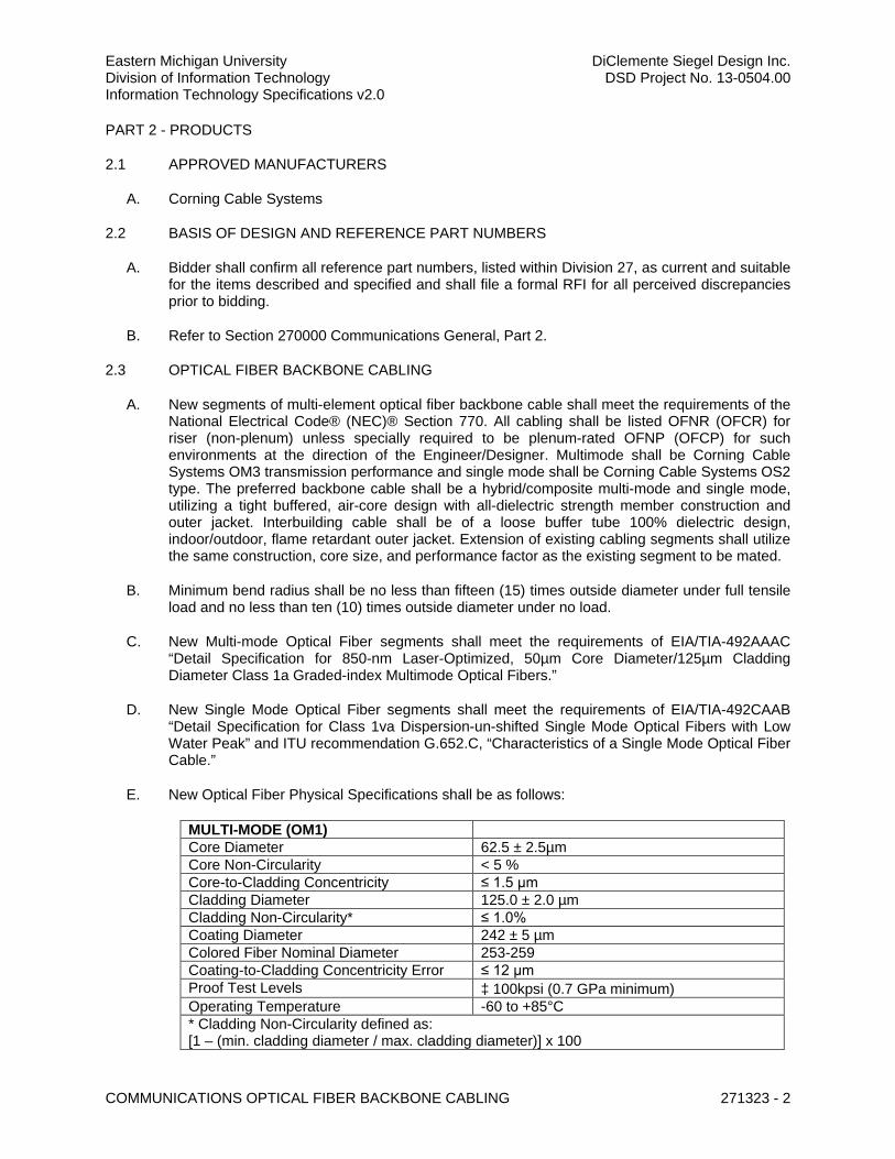
Eastern Michigan University DiClemente Siegel Design Inc. Division of Information Technology DSD Project No. 13-0504.00 Information Technology Specifications v2.0
COMMUNICATIONS OPTICAL FIBER BACKBONE CABLING 271323 - 2
PART 2 - PRODUCTS
2.1 APPROVED MANUFACTURERS
A. Corning Cable Systems
2.2 BASIS OF DESIGN AND REFERENCE PART NUMBERS
A. Bidder shall confirm all reference part numbers, listed within Division 27, as current and suitable for the items described and specified and shall file a formal RFI for all perceived discrepancies prior to bidding.
B. Refer to Section 270000 Communications General, Part 2.
2.3 OPTICAL FIBER BACKBONE CABLING
A. New segments of multi-element optical fiber backbone cable shall meet the requirements of the National Electrical Code® (NEC)® Section 770. All cabling shall be listed OFNR (OFCR) for riser (non-plenum) unless specially required to be plenum-rated OFNP (OFCP) for such environments at the direction of the Engineer/Designer. Multimode shall be Corning Cable Systems OM3 transmission performance and single mode shall be Corning Cable Systems OS2 type. The preferred backbone cable shall be a hybrid/composite multi-mode and single mode, utilizing a tight buffered, air-core design with all-dielectric strength member construction and outer jacket. Interbuilding cable shall be of a loose buffer tube 100% dielectric design, indoor/outdoor, flame retardant outer jacket. Extension of existing cabling segments shall utilize the same construction, core size, and performance factor as the existing segment to be mated.
B. Minimum bend radius shall be no less than fifteen (15) times outside diameter under full tensile load and no less than ten (10) times outside diameter under no load.
C. New Multi-mode Optical Fiber segments shall meet the requirements of EIA/TIA-492AAAC “Detail Specification for 850-nm Laser-Optimized, 50µm Core Diameter/125µm Cladding Diameter Class 1a Graded-index Multimode Optical Fibers.”
D. New Single Mode Optical Fiber segments shall meet the requirements of EIA/TIA-492CAAB “Detail Specification for Class 1va Dispersion-un-shifted Single Mode Optical Fibers with Low Water Peak” and ITU recommendation G.652.C, “Characteristics of a Single Mode Optical Fiber Cable.”
E. New Optical Fiber Physical Specifications shall be as follows:
MULTI-MODE (OM1) Core Diameter 62.5 ± 2.5µm Core Non-Circularity < 5 % Core-to-Cladding Concentricity ≤ 1.5 µm Cladding Diameter 125.0 ± 2.0 µm Cladding Non-Circularity* ≤ 1.0% Coating Diameter 242 ± 5 µm Colored Fiber Nominal Diameter 253-259 Coating-to-Cladding Concentricity Error ≤ 12 µm Proof Test Levels ³ 100kpsi (0.7 GPa minimum) Operating Temperature -60 to +85°C * Cladding Non-Circularity defined as: [1 – (min. cladding diameter / max. cladding diameter)] x 100
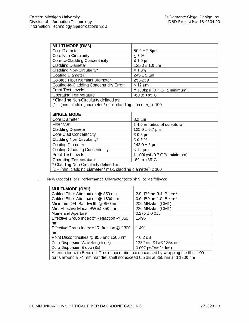
Eastern Michigan University DiClemente Siegel Design Inc. Division of Information Technology DSD Project No. 13-0504.00 Information Technology Specifications v2.0
COMMUNICATIONS OPTICAL FIBER BACKBONE CABLING 271323 - 3
MULTI-MODE (OM3) Core Diameter 50.0 ± 2.5µm Core Non-Circularity < 5 % Core-to-Cladding Concentricity ≤ 1.5 µm Cladding Diameter 125.0 ± 1.0 µm Cladding Non-Circularity* ≤ 1.0% Coating Diameter 245 ± 5 µm Colored Fiber Nominal Diameter 253-259 Coating-to-Cladding Concentricity Error ≤ 12 µm Proof Test Levels ³ 100kpsi (0.7 GPa minimum) Operating Temperature -60 to +85°C * Cladding Non-Circularity defined as: [1 – (min. cladding diameter / max. cladding diameter)] x 100
SINGLE MODE Core Diameter 8.2 µm Fiber Curl ³ 4.0 m radius of curvature Cladding Diameter 125.0 ± 0.7 µm Core-Clad Concentricity £ 0.5 µm Cladding Non-Circularity* £ 0.7 % Coating Diameter 242.0 ± 5 µm Coating-Cladding Concentricity < 12 µm Proof Test Levels ³ 100kpsi (0.7 GPa minimum) Operating Temperature -60 to +85°C * Cladding Non-Circularity defined as: [1 – (min. cladding diameter / max. cladding diameter)] x 100
F. New Optical Fiber Performance Characteristics shall be as follows:
MULTI-MODE (OM1) Cabled Fiber Attenuation @ 850 nm 2.9 dB/km* 3.4dB/km** Cabled Fiber Attenuation @ 1300 nm 0.6 dB/km* 1.0dB/km** Minimum OFL Bandwidth @ 850 nm 200 MHz/km (OM1) Min. Effective Modal BW @ 850 nm 220 MHz/km (OM1) Numerical Aperture 0.275 ± 0.015 Effective Group Index of Refraction @ 850 nm
1.496
Effective Group Index of Refraction @ 1300 nm
1.491
Point Discontinuities @ 850 and 1300 nm < 0.2 dB Zero Dispersion Wavelength (l0) 1332 nm £ l0 £ 1354 nm Zero Dispersion Slope (S0) 0.097 ps/(nm2 · km) Attenuation with Bending: The induced attenuation caused by wrapping the fiber 100 turns around a 74 mm mandrel shall not exceed 0.5 dB at 850 nm and 1300 nm
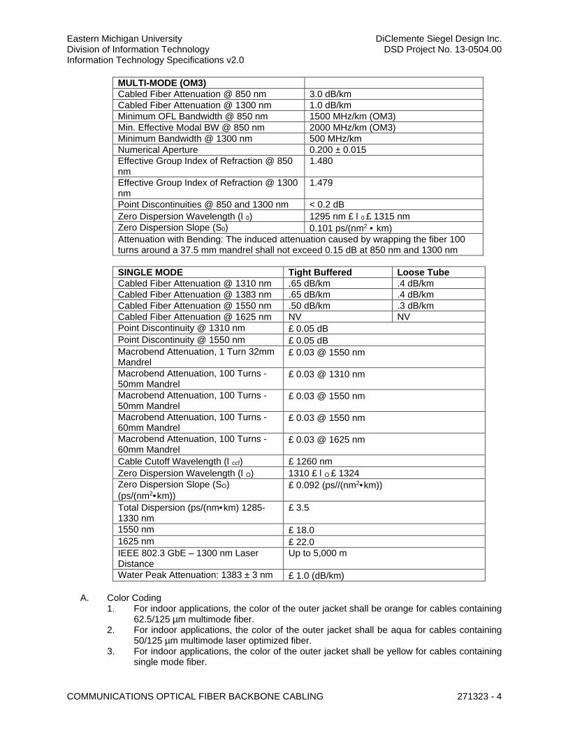
Eastern Michigan University DiClemente Siegel Design Inc. Division of Information Technology DSD Project No. 13-0504.00 Information Technology Specifications v2.0
COMMUNICATIONS OPTICAL FIBER BACKBONE CABLING 271323 - 4
MULTI-MODE (OM3) Cabled Fiber Attenuation @ 850 nm 3.0 dB/km Cabled Fiber Attenuation @ 1300 nm 1.0 dB/km Minimum OFL Bandwidth @ 850 nm 1500 MHz/km (OM3) Min. Effective Modal BW @ 850 nm 2000 MHz/km (OM3) Minimum Bandwidth @ 1300 nm 500 MHz/km Numerical Aperture 0.200 ± 0.015 Effective Group Index of Refraction @ 850 nm
1.480
Effective Group Index of Refraction @ 1300 nm
1.479
Point Discontinuities @ 850 and 1300 nm < 0.2 dB Zero Dispersion Wavelength (l0) 1295 nm £ l0 £ 1315 nm Zero Dispersion Slope (S0) 0.101 ps/(nm2 · km) Attenuation with Bending: The induced attenuation caused by wrapping the fiber 100 turns around a 37.5 mm mandrel shall not exceed 0.15 dB at 850 nm and 1300 nm
SINGLE MODE Tight Buffered Loose Tube Cabled Fiber Attenuation @ 1310 nm .65 dB/km .4 dB/km Cabled Fiber Attenuation @ 1383 nm .65 dB/km .4 dB/km Cabled Fiber Attenuation @ 1550 nm .50 dB/km .3 dB/km Cabled Fiber Attenuation @ 1625 nm NV NV Point Discontinuity @ 1310 nm £ 0.05 dB Point Discontinuity @ 1550 nm £ 0.05 dB Macrobend Attenuation, 1 Turn 32mm Mandrel
£ 0.03 @ 1550 nm
Macrobend Attenuation, 100 Turns - 50mm Mandrel
£ 0.03 @ 1310 nm
Macrobend Attenuation, 100 Turns - 50mm Mandrel
£ 0.03 @ 1550 nm
Macrobend Attenuation, 100 Turns - 60mm Mandrel
£ 0.03 @ 1550 nm
Macrobend Attenuation, 100 Turns - 60mm Mandrel
£ 0.03 @ 1625 nm
Cable Cutoff Wavelength (lccf) £ 1260 nm Zero Dispersion Wavelength (lO) 1310 £ lO £ 1324 Zero Dispersion Slope (SO) (ps/(nm2·km))
£ 0.092 (ps//(nm2·km))
Total Dispersion (ps/(nm·km) 1285-1330 nm
£ 3.5
1550 nm £ 18.0 1625 nm £ 22.0 IEEE 802.3 GbE – 1300 nm Laser Distance
Up to 5,000 m
Water Peak Attenuation: 1383 ± 3 nm £ 1.0 (dB/km)
A. Color Coding 1. For indoor applications, the color of the outer jacket shall be orange for cables containing
62.5/125 µm multimode fiber. 2. For indoor applications, the color of the outer jacket shall be aqua for cables containing
50/125 µm multimode laser optimized fiber. 3. For indoor applications, the color of the outer jacket shall be yellow for cables containing
single mode fiber.
Eastern Michigan University DiClemente Siegel Design Inc. Division of Information Technology DSD Project No. 13-0504.00 Information Technology Specifications v2.0
COMMUNICATIONS OPTICAL FIBER BACKBONE CABLING 271323 - 5
4. For outside plant applications, the jacket shall contain carbon black to provide ultraviolet light protection.
5. The optical fiber color coding shall be in accordance with EIA/TIA-598-B, "Optical Fiber Cable Color Coding."
B. Each optical fiber backbone cable shall consist of a minimum number of individual elements specified within the Project Drawings. All optical fiber cables shall be shipped with OTDR results for each fiber. OTDR results shall show attenuation and bandwidth. The results shall be documented in such a manner that the information can be retained for future use.
2.4 INNERDUCT
A. Innerduct shall not be required unless specifically indicated to fill empty conduits for future cable capacity.
B. If specifically indicated, innerduct shall be riser rated, as required for the environment in which it is placed.
C. Where used, Innerduct shall be flexible, corrugated, and non-metallic.
D. Innerduct shall be 1” and 1-1/4" diameter.
E. Innerduct shall NOT be required where optical fiber cabling construction is jacketed interlocking armor.
PART 3 - EXECUTION
3.1 FIELD CONDITIONS
A. Examine all elements intended for Communications. Check pathways, raceways, cable trays, and other elements for compliance with space allocations, installation tolerances, installation hazards or impediments, and other conditions affecting installation. Verify that all work required in the field is adequately described in the plans. Proceed with installation only after unsatisfactory conditions and discrepancies have been brought to the attention of the General Contractor and corrected.
B. Unless otherwise noted, the footages for cabling and materials shown on the Project Drawings are based upon available plant records, architectural drawings, or the Engineer/Designer’s route and pathway assumptions. The Contractor shall be required to perform field surveys and measurements, prior to ordering materials.
3.2 INSTALLATION
A. Place cables without exceeding cable manufacturer’s recommended pulling tensions. 1. Pull cables simultaneously if more than one is being pulled in the same raceway. 2. Use pulling compound or lubricant if necessary. Use compounds that will not damage
conductor or insulation. 3. Use pulling means, including fish tape, cable, rope, and basket weave or cable grips, that
will not damage cabling or raceways.
B. Contractor shall include a minimum of fifteen (15) foot single service loop, secured to the DC ceiling deck or cable runway prior to completing the run to the optical fiber distribution panel within the floor mounted equipment rack or cabinet.

Eastern Michigan University DiClemente Siegel Design Inc. Division of Information Technology DSD Project No. 13-0504.00 Information Technology Specifications v2.0
COMMUNICATIONS OPTICAL FIBER BACKBONE CABLING 271323 - 6
C. Contractor shall include a minimum of two (2) foot single service loop, secured within the optical fiber connector housing prior to completing termination at the connector panel.
D. All DC cabling shall be continuous and without splices of any kind.
E. Cabling shall be arranged on the distribution panels in sequential numerical order by individual element according to optical fiber color code.
F. Optical Fiber Backbone Cabling shall be terminated as follows. 1. Optical Fiber Distribution Panels shall be rack mount enclosures with front and rear
removable doors, removable top, large front-mounted fiber guides, and integrated hinged optical jumper manager. “144-Port” housings shall accept up to twelve (12) connector panels, supporting a maximum of one-hundred forty-four (144) “LC” style couplings in 4U rack space. “48-port” housings shall accept up to four (4) connector panels, supporting a maximum of forty-eight (48) “LC” style couplings in 2U rack space Each panel shall include a full complement of blank adapter panels, labels, cable storage accessories, hardware grounding kits, and optical fiber cable routing accessory kit.
G. Prior to shipment, both cable ends shall be sealed with a waterproof cap to prevent moisture from entering the cable.
H. The cable reel shall be shipped with OTDR results for each fiber. OTDR results shall show attenuation and bandwidth. The results shall be documented in such a manner that the information can be retained for future use.
3.3 CERTIFICATION TESTING
A. The Division 27 Contractor shall be required to field demonstrate the testing and test equipment calibration procedures to the Engineer/Designer and/or DoIT Engineer. The Contractor shall confirm the demonstration requirement before the scheduling field test operations.
B. Full testing shall be performed on each cabling segment (connector to connector). Perform the listed tests and inspections and prepare full reports to be submitted immediately upon completion of each phase of construction as well as for inclusion in O&M Manuals.
C. All optical fiber elements/strands shall be 100% tested and documented as per procedures contained herein. All fiber elements/strands shall be useable.
D. Fiber end faces shall be inspected at 250X or 400X magnification. 250X magnification is suitable for inspecting multimode and single mode fibers. 400X magnification may be used for detailed examination of single mode fibers. Scratched, pitted or dirty connectors shall be diagnosed and corrected. It is preferable that the end face images be recorded in the memory of the test instrument for subsequent uploading to a PC and reporting.
E. Unless pre-approved by EMU DoIT, all fiber certification testing shall be performed using test instruments manufactured by Fluke Networks or Corning Cable Systems. Test results shall be provided using Fluke or Corning Management Software to be provided to the Owner as part of the project documentation delivery. All Field-test instruments shall have the latest software and firmware installed. Calibration of the testing instruments shall be current as per manufacturer’s specifications. Test cords, adapters, and connectors shall be clean and maintained in good order. Test instruments shall be identified on the test summary forms as to make, model, software generic, and calibration date.
Eastern Michigan University DiClemente Siegel Design Inc. Division of Information Technology DSD Project No. 13-0504.00 Information Technology Specifications v2.0
COMMUNICATIONS OPTICAL FIBER BACKBONE CABLING 271323 - 7
F. All tests shall be performed by trained technicians who have been certified by Corning Cable Systems as an NPI (Network of Preferred Installers) Program. The Cabling Contractor, installer, tester, and warranty issuer shall be employed by the same NPI firm.
G. Testing of the cabling shall be performed using high-quality test cords of the same fiber type as the cabling under test. The test cords for OLTS testing shall be between 1m and 5m in length. A launch cable and mandrel shall be installed between the OTDR and the first link connection and a receive cable shall be installed after the last link connection. The test cords for OTDR testing shall be approximately 100m for the launch cable and at least 25 m for the receive cable.
H. Link attenuation shall not include any active devices or passive devices other than cable, connectors, and splices, i.e. link attenuation shall not include such devices as optical bypass switches, couplers, repeaters, or optical amplifiers.
I. The Contractor shall perform a Tier 1 (attenuation, length, and polarity) certification test for each optical fiber element/strand.
J. The Contractor shall perform a Tier 2 (OTDR) certification test for each optical fiber element/strand.
K. Backbone links shall be testing according to ANSI/TIA-568-C.
L. Multimode shall be tested at 850nm and 1300nm wavelengths in accordance with ANSI/EIA/TIA-526-14A, Method B, One Reference Jumper or the equivalent method.
M. Single mode shall be tested at 1310 nm and 1550 nm in accordance with ANSI/TIA/EIA-526-7, Method A.1, One Reference Jumper or the equivalent method.
N. Optical fiber connector and splicing losses shall not exceed the following. 1. Connector losses shall not exceed .75dB per mated pair. 2. Connector loss combined with a pigtail fusion splice shall not exceed .90dB loss per
mated pair. 3. Fusion splices shall not exceed 0.15dB loss.
O. The length of each fiber shall be recorded. It is preferable that the optical length be measured using an OLTS or OTDR. Physical length measurements from manufacturer cable markings shall also be acceptable.
P. The detailed test results documentation data is to be provided in an electronic database for each tested optical fiber and shall contain the following information at minimum. 1. Identification of the customer site as specified by the end-user 2. Name of the test limit selected to execute the stored test results 3. Name of the personnel performing the test 4. Date and time the test results were saved in the memory of the tester 5. Manufacturer, model and serial number of the field-test instrument 6. Version of the test software and the version of the test limit database held within the test
instrument 7. Fiber identification number 8. Length for each optical fiber 9. Optionally the index of refraction used for length calculation when using a length capable
OLTS 10. Test results to include OLTS attenuation link and channel measurements at the
appropriate wavelength(s) and the margin (difference between the measured attenuation and the test limit value).
Eastern Michigan University DiClemente Siegel Design Inc. Division of Information Technology DSD Project No. 13-0504.00 Information Technology Specifications v2.0
COMMUNICATIONS OPTICAL FIBER BACKBONE CABLING 271323 - 8
11. Test results to include OTDR link and channel traces and event tables at the appropriate wavelength(s).
12. The length for each optical fiber as calculated by the OTDR. 13. The overall Pass/Fail evaluation of the link-under-test for OLTS and OTDR
measurements.
Q. The Contractor shall provide 48-hours’ notice to the Engineer/Designer and DoIT Engineer prior to commencement of cable testing. The Engineer/Designer and DoIT Engineer shall, at his discretion, be present to observe any and all cable test procedures. Cable testing procedures shall be acceptable to the Engineer/Designer.
R. The Contractor shall produce test reports to be accepted by the Engineer/Designer or the DoIT Engineer. Test reports shall be completely and legibly filled out, dated, and signed by the person performing the tests. The completed forms shall be submitted to the General Contractor for review and acceptance by the Engineer/Designer or the DoIT Engineer.
S. All optical fiber connectors shall be thoroughly cleaned and end-caps installed after the test procedures have been completed.
3.4 LABELING
A. Labeling shall be furnished and installed by the Contractor. Contractor shall make early contact with DoIT Engineer to obtain the approved identifier and any other special requirements for each project.
B. General: Mechanically printed, adhesive labels shall be used in all cases. Labels shall have a white background with black lettering. Brady ID Pro label tape is recommended for the backbone jacket labels. Brother P-Touch labels are recommended for all other labels.
C. Backbone Cable Jacket: All cables shall be labeled using a mechanically printed label, designed for use on cable sheathing, at each end. Labels shall contain the approved identifier for the start and end destination, followed by the sequence number and strand (element) count. All cable labels shall be mechanically printed, wrap-around self-laminating type.
END OF SECTION 271323
271513 - COMMUNICATIONS HORIZONTAL CABLING
Eastern Michigan University DiClemente Siegel Design Inc. Division of Information Technology DSD Project No. 13-0504.00 Information Technology Specifications v2.0
COMMUNICATIONS HORIZONTAL CABLING 271513 - 1
SECTION 271513 – COMMUNICATIONS HORIZONTAL CABLING
PART 1 - GENERAL
1.1 RELATED DOCUMENTS
A. Drawings and general provisions of the Contract, including General and Supplementary Conditions and Division 01 Specification Sections, apply to this Section
B. Section 270000 – Communications General
C. Section 270500 – Common Work Results for Communications
D. Section 271116 – Communications Cabinets, Racks, Frames, and Enclosures
E. Section 271120 – Communications Horizontal Termination Hardware
F. Section 271123 – Communications Cable Management and Runway
G. Section 271543 – Communications Faceplates and Connectors
H. Section 271619 – Communications Patch Cords, Station Cords, and Cross-Connect Wires
1.2 CODES AND STANDARDS
A. Refer to Section 270000 – Communications General
B. Refer to Division 01, where project applicable.
1.3 SUMMARY OF WORK
A. This Section includes: 1. Horizontal Cabling (copper) for “Data”, “Voice”, and “Video”. 2. Horizontal Cabling (optical fiber) for non-TR based “Data” and “Video” applications. Note
that not all projects include horizontal fiber. Refer to Project Drawings for all requirements.
B. Furnish and install new horizontal Category 6 “Data” Cabling from Telecommunications Rooms to WAO and TO locations as indicated on Plans. Furnish and install new jacks. Terminate, test, label, and document all locations.
C. Furnish and install new horizontal Category 6 “Voice” Cabling from Telecommunications Rooms to WAO and TO locations as indicated on Plans. Furnish and install new jacks. Terminate, test, label, and document all locations.
D. Division 27 shall be required to remove obstructing furniture in close coordination with the Project Manager.
1.4 DEFINITIONS
A. Refer to Section 270000 – Communications General
Eastern Michigan University DiClemente Siegel Design Inc. Division of Information Technology DSD Project No. 13-0504.00 Information Technology Specifications v2.0
COMMUNICATIONS HORIZONTAL CABLING 271513 - 2
1.5 ACRONYMS & ABBREVIATIONS
A. Refer to Section 270000 – Communications General
1.6 SUBMITTALS
A. Refer to Section 270000 – Communications General
PART 2 - PRODUCTS
2.1 APPROVED MANUFACTURERS
A. Products by the following manufacturers shall be considered equal where applied to the Basis of Design and Reference Part Number listed within this section for the certified structured cabling solution. 1. Belden 2. Berk-Tek 3. Commscope 4. Corning Cable Systems (if horizontal optical fiber is indicated in Project Drawings) 5. EMU approved equal, documented by a pre-bid addendum
2.2 BASIS OF DESIGN AND REFERENCE PART NUMBERS
A. Bidder shall confirm all reference part numbers, listed within Division 27, as current and suitable for the items described and specified and shall file a formal RFI for all perceived discrepancies prior to bidding.
B. Refer to Section 270000 Communications General, Part 2.
2.3 COPPER HORIZONTAL CABLING FOR DATA/VOICE/VIDEO
A. The Horizontal System is the portion of the telecommunications cabling system that extends from the TO (Telecommunications Outlet) connector to the HC (Horizontal Cross-connect), located in the ER (Equipment Room) or TR (Telecommunications Room). It consists of the telecommunications outlet/connector, horizontal cables, optional CP (Consolidation Point) if indicated in the Project Drawings, and that portion of cross-connect in the ER/TR serving the horizontal cabling. Each floor of a building should be served by a distinct Horizontal System, unless otherwise indicated in the Project Drawings. 1. Horizontal cabling for “Data” shall be performance rated EIA/TIA Category 6, at minimum.
All cables shall be imprinted by the manufacturer as Category 6. 2. Horizontal cabling for “Voice” shall be performance rated EIA/TIA Category 6, at
minimum. All cables shall be imprinted by the manufacturer as Category 6. 3. All cabling shall consist of four (4) unshielded twisted pairs, 23 AWG (Category 6) solid
bare copper conductors, color-coded per the band strip color coding conventional standard as follows: a. Pair #1 - White/Blue-Blue/White b. Pair #2 - White/Orange-Orange/White c. Pair #3 - White/Green-Green/White d. Pair #4 - White/Brown-Brown/White
4. All Horizontal system cables shall marked CMP or CMR (as minimum requirement) for the environment in which they are to be installed. These markings shall also include the name of the cable manufacturer and the category performance rating. Cable jacket shall be sequentially marked at 2-foot intervals.
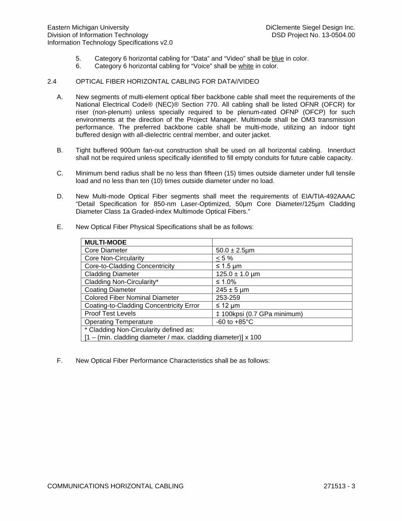
Eastern Michigan University DiClemente Siegel Design Inc. Division of Information Technology DSD Project No. 13-0504.00 Information Technology Specifications v2.0
COMMUNICATIONS HORIZONTAL CABLING 271513 - 3
5. Category 6 horizontal cabling for “Data” and “Video” shall be blue in color. 6. Category 6 horizontal cabling for “Voice” shall be white in color.
2.4 OPTICAL FIBER HORIZONTAL CABLING FOR DATA//VIDEO
A. New segments of multi-element optical fiber backbone cable shall meet the requirements of the National Electrical Code® (NEC)® Section 770. All cabling shall be listed OFNR (OFCR) for riser (non-plenum) unless specially required to be plenum-rated OFNP (OFCP) for such environments at the direction of the Project Manager. Multimode shall be OM3 transmission performance. The preferred backbone cable shall be multi-mode, utilizing an indoor tight buffered design with all-dielectric central member, and outer jacket.
B. Tight buffered 900um fan-out construction shall be used on all horizontal cabling. Innerduct shall not be required unless specifically identified to fill empty conduits for future cable capacity.
C. Minimum bend radius shall be no less than fifteen (15) times outside diameter under full tensile load and no less than ten (10) times outside diameter under no load.
D. New Multi-mode Optical Fiber segments shall meet the requirements of EIA/TIA-492AAAC “Detail Specification for 850-nm Laser-Optimized, 50µm Core Diameter/125µm Cladding Diameter Class 1a Graded-index Multimode Optical Fibers.”
E. New Optical Fiber Physical Specifications shall be as follows:
MULTI-MODE Core Diameter 50.0 ± 2.5µm Core Non-Circularity < 5 % Core-to-Cladding Concentricity ≤ 1.5 µm Cladding Diameter 125.0 ± 1.0 µm Cladding Non-Circularity* ≤ 1.0% Coating Diameter 245 ± 5 µm Colored Fiber Nominal Diameter 253-259 Coating-to-Cladding Concentricity Error ≤ 12 µm Proof Test Levels ³ 100kpsi (0.7 GPa minimum) Operating Temperature -60 to +85°C * Cladding Non-Circularity defined as: [1 – (min. cladding diameter / max. cladding diameter)] x 100
F. New Optical Fiber Performance Characteristics shall be as follows:
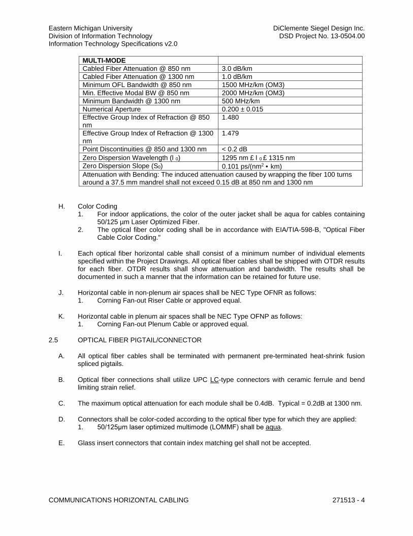
Eastern Michigan University DiClemente Siegel Design Inc. Division of Information Technology DSD Project No. 13-0504.00 Information Technology Specifications v2.0
COMMUNICATIONS HORIZONTAL CABLING 271513 - 4
MULTI-MODE Cabled Fiber Attenuation @ 850 nm 3.0 dB/km Cabled Fiber Attenuation @ 1300 nm 1.0 dB/km Minimum OFL Bandwidth @ 850 nm 1500 MHz/km (OM3) Min. Effective Modal BW @ 850 nm 2000 MHz/km (OM3) Minimum Bandwidth @ 1300 nm 500 MHz/km Numerical Aperture 0.200 ± 0.015 Effective Group Index of Refraction @ 850 nm
1.480
Effective Group Index of Refraction @ 1300 nm
1.479
Point Discontinuities @ 850 and 1300 nm < 0.2 dB Zero Dispersion Wavelength (l0) 1295 nm £ l0 £ 1315 nm Zero Dispersion Slope (S0) 0.101 ps/(nm2 · km) Attenuation with Bending: The induced attenuation caused by wrapping the fiber 100 turns around a 37.5 mm mandrel shall not exceed 0.15 dB at 850 nm and 1300 nm
H. Color Coding 1. For indoor applications, the color of the outer jacket shall be aqua for cables containing
50/125 µm Laser Optimized Fiber. 2. The optical fiber color coding shall be in accordance with EIA/TIA-598-B, "Optical Fiber
Cable Color Coding."
I. Each optical fiber horizontal cable shall consist of a minimum number of individual elements specified within the Project Drawings. All optical fiber cables shall be shipped with OTDR results for each fiber. OTDR results shall show attenuation and bandwidth. The results shall be documented in such a manner that the information can be retained for future use.
J. Horizontal cable in non-plenum air spaces shall be NEC Type OFNR as follows: 1. Corning Fan-out Riser Cable or approved equal.
K. Horizontal cable in plenum air spaces shall be NEC Type OFNP as follows: 1. Corning Fan-out Plenum Cable or approved equal.
2.5 OPTICAL FIBER PIGTAIL/CONNECTOR
A. All optical fiber cables shall be terminated with permanent pre-terminated heat-shrink fusion spliced pigtails.
B. Optical fiber connections shall utilize UPC LC-type connectors with ceramic ferrule and bend limiting strain relief.
C. The maximum optical attenuation for each module shall be 0.4dB. Typical = 0.2dB at 1300 nm.
D. Connectors shall be color-coded according to the optical fiber type for which they are applied: 1. 50/125μm laser optimized multimode (LOMMF) shall be aqua.
E. Glass insert connectors that contain index matching gel shall not be accepted.
Eastern Michigan University DiClemente Siegel Design Inc. Division of Information Technology DSD Project No. 13-0504.00 Information Technology Specifications v2.0
COMMUNICATIONS HORIZONTAL CABLING 271513 - 5
PART 3 - EXECUTION
3.1 FIELD CONDITIONS
A. Examine all elements intended for Communications. Check pathways, raceways, cable trays, and other elements for compliance with space allocations, installation tolerances, installation hazards or impediments, and other conditions affecting installation. Verify that all work required in the field is adequately described in the plans. Proceed with installation only after unsatisfactory conditions and discrepancies have been brought to the attention of the Construction Manager and corrected.
B. Unless otherwise noted, the footages for cabling and materials shown on the project drawings are based upon available plant records, architectural drawings, or the Engineer/Designer’s route and pathway assumptions. The Contractor shall be required to perform field surveys and measurements, prior to ordering materials.
3.2 INSTALLATION
A. Horizontal copper cabling runs shall be placed in one continuous end-to-end length between the ER or TR and the WAO or TO, without splices of any kind.
B. Unless otherwise specified, this contractor shall be responsible furnish and install complete J-Hook runs at 5 ft. (maximum) intervals along the entire cable route with each serving zone and in parallel with existing cable tray structure in the overhead ceiling space. Attaching or otherwise draping cables to ceiling wire grid, pipes by other trades, lighting fixtures, etc. shall not be permitted.
C. J-Hooks and other independent cable supports shall be located on 48” to 60” centers to adequately support and distribute the cable weight.
D. Where J-Hooks and independent cable supports are used, runs shall follow walls and building supporting structures; diagonal runs shall not be acceptable.
E. Place cables without exceeding cable manufacturer’s recommended pulling tensions. 1. Pull cables simultaneously if more than one is being pulled in the same raceway. 2. Use pulling compound or lubricant only if necessary. Use compounds that will not
damage conductor or insulation. 3. Use pulling means, including fish tape, cable, rope, and basket weave or cable grips, that
will not damage cabling or raceways.
F. Category 6 “Voice” Station Cables shall be terminated on 110 blocks separate from those used for Riser cable and shall be mounted on plywood backboard. D-Rings shall be furnished and installed for cross-connect management. The Station cables shall be routed from the overhead ladder rack to a designated corner of the TR. From there, they will be routed to comprise a long service loop of cable upon the ladder rack of the TR. The length of this service loop shall be sufficient to re-terminate all cables within new rack mounted Patch Panels as needed in the future. After the service loop, all cabling shall be routed through metal D-Rings and approach the point of termination. All cables shall be neatly organized and dressed (combed) using Velcro strap material (instead of tie wraps). Cable management hardware shall be furnished and installed by the contractor to ensure that the installation is neatly organized and readily identifiable.
G. Category 6 Data/Video Station Cables shall be terminated on rack mounted patch panels within the designated TR according to EIA/TIA 568B pinning arrangements. All Category 6 cables for

Eastern Michigan University DiClemente Siegel Design Inc. Division of Information Technology DSD Project No. 13-0504.00 Information Technology Specifications v2.0
COMMUNICATIONS HORIZONTAL CABLING 271513 - 6
“Data” service shall be neatly organized and dressed following industry-standard practices and in conformance with installation standards of Division 27 specifications. Each patch panel start with the lowest outlet location number and increase in sequence from left to right, top to bottom. The Station cables shall be routed from the overhead ladder rack to a designated corner of the TR. From there, they will be routed to comprise a long service loop of cable upon the ladder rack of the TR. The length of this service loop shall be sufficient to pull back and re-terminate cables, as needed in the future, on wall mounted 110 blocks in the event cables must be hard-wired for life-safety, or other reasons, as required by the Project Manager. All cables shall be neatly organized and dressed (combed) using Velcro strap material (instead of tie wraps). Cable management hardware shall be furnished and installed by the contractor to ensure that the installation is neatly organized and readily identifiable.
3.3 CERTIFICATION TESTING
A. Unless pre-approved by the Project Manager, all copper certification testing shall be performed using test equipment manufactured by Fluke Networks. Test results shall be provided using Fluke Networks Linkware Management Software.
B. Test equipment shall be equipped with the most current software upgrades to meet applicable testing standards. Calibration of the testing instruments shall be current as per the manufacturer’s requirements. Test cords, adapters, and connectors shall be maintained in good order. Test instruments must be identified on the applicable summary test forms as to make, model, software generic, and calibration date.
C. This Contractor may be required to field demonstrate the calibration and testing procedures to the Project Manager. The Project Manager shall confirm the demonstration requirement prior to start of field test operations.
D. Full testing shall be performed on each Category 6 permanent link (Patch Panel to Patch Panel and Patch Panel to Work Area Outlet) by trained technicians who have successfully attended an appropriate training program and have obtained a certificate as proof thereof. The test of each link shall include all of the parameters as detailed below. In order to pass, the test measurements must all meet or exceed the limit value determined in the TIA/EIA Category 6 Standard. Perform and record the tests and prepare full reports for inclusion in O&M Manuals.
E. All new cable pairs shall be 100% tested and passed by the criteria as established herein.
F. Autotest settings, provided in the field tester for testing the installed cabling, shall be set to the manufacturer default parameters for the type and characteristics of the cable to be tested including NVP (Nominal Velocity of Propagation).
G. Tests shall be performed with connectors and termination completed and in-place.
H. The Division 27 Contractor shall provide forty-eight (48) hours’ notice to the Engineer/Designer and DoIT Engineer prior to commencement of cable testing. The Engineer/Designer shall, at his discretion, be present to observe any and all cable test procedures. Cable testing procedures shall be acceptable to the Engineer/Designer.
I. This Contractor shall produce summary test reports to be accepted by the Engineer/Designer at the completion of each project phase. Test reports shall be completely and legibly filled out, dated, and signed by the person performing the tests. The completed forms shall be submitted to the Engineer/Designer for review and acceptance for authorization to proceed into the next installation phase.
Eastern Michigan University DiClemente Siegel Design Inc. Division of Information Technology DSD Project No. 13-0504.00 Information Technology Specifications v2.0
COMMUNICATIONS HORIZONTAL CABLING 271513 - 7
J. Non-compliant horizontal cables shall be replaced with new materials, and re-tested as specified.
K. Any cable or component not satisfactorily passing the tests as described or failing to meet quality installation standards as described in this specification, shall be repaired and/or replaced at the Contractor's expense.
L. The Contractor shall prepare final and complete cable test reports for all installed cables for review and approval of the Project Manager prior to acceptance of the cabling system. Final and complete test results shall be included within O&M Manuals. Refer to Section 270000 Communications General, Submittals.
M. A copy of the final completed and reviewed cable test reports shall be enclosed in clear vinyl protective covers and posted in all ER and TR spaces for use and reference by the Project Manager.
3.4 LABELING
A. Labeling shall be furnished and installed by the contractor according to the following details. Contractor shall make early contact with the DoIT Engineer to obtain the three-letter identifier and any other special requirements for each project. Example labels are available upon request.
B. General: Mechanically printed, adhesive labels shall be used in all cases except for 110 blocks. Labels shall have a white background with black lettering. Brady ID Pro label tape is recommended for the riser and station jacket labels. Brother P-Touch labels are recommended for all other labels.
C. Station Cable Jacket: All cables will be labeled using a mechanically printed label, designed for use on cable sheathing, at each end. These cable labels will contain the outlet number, location number, and jack number on one line, separated by dashes. The TR designation in which the cable is terminated shall be contained on a second line. Cable jacket labels will be installed between 6 inches and 10 inches from the terminated cable end.
3.5 FIRESTOPPING
A. Firestopping shall be installed after all cabling under contract has been installed.
END OF SECTION 271119
271543 - COMMUNICATIONS FACEPLATES AND CONNECTORS
Eastern Michigan University DiClemente Siegel Design Inc. Division of Information Technology DSD Project No. 13-0504.00 Information Technology Specifications v2.0
COMMUNICATIONS FACEPLATES AND CONNECTORS 271543 - 1
SECTION 271543 – COMMUNICATIONS FACEPLATES AND CONNECTORS
PART 1 - GENERAL
1.1 RELATED DOCUMENTS
A. Drawings and general provisions of the Contract, including General and Supplementary Conditions and Division 01 Specification Sections, apply to this Section
B. Section 270000 – Communications General
C. Section 270500 – Common Work Results for Communications
D. Section 271116 – Communications Cabinets, Racks, Frames, and Enclosures
E. Section 271120 – Communications Horizontal Termination Hardware
F. Section 271123 – Communications Cable Management and Runway
G. Section 271513 – Communications Horizontal Cabling
H. Section 271619 – Communications Patch Cords, Station Cords, and Cross-Connect Wires
1.2 CODES AND STANDARDS
A. Refer to Section 270000 – Communications General
B. Refer to Division 01, where project applicable.
1.3 SUMMARY OF WORK
A. This Section includes: 1. Faceplates and Housings for Work Area Outlets (WAOs) and Telecommunications
Outlets (TOs). 2. Modular Jacks and Outlets for termination of “Data”, “Voice”, and “Video” cabling at
WAOs and TOs.
B. Furnish and install new horizontal Category 6 “Data” Cabling from Telecommunications Rooms to WAO and TO locations as indicated on Plans. Furnish and install new jacks. Terminate, test, label, and document all locations.
C. “Furnish and install new horizontal Category 6 “Voice” Cabling from Telecommunications Rooms to WAO and TO locations as indicated on Plans. Furnish and install new jacks. Terminate, test, label, and document all locations.
D. Division 27 shall be required to remove obstructing furniture in close coordination with the Owner.
1.4 DEFINITIONS
A. Refer to Section 270000 – Communications General
Eastern Michigan University DiClemente Siegel Design Inc. Division of Information Technology DSD Project No. 13-0504.00 Information Technology Specifications v2.0
COMMUNICATIONS FACEPLATES AND CONNECTORS 271543 - 2
1.5 ACRONYMS & ABBREVIATIONS
A. Refer to Section 270000 – Communications General
1.6 SUBMITTALS
A. Refer to Section 270000 – Communications General
PART 2 - PRODUCTS
2.1 APPROVED MANUFACTURERS
A. Products by the following manufacturers shall be considered equal where applied to the Basis of Design and Reference Part Number listed within this section. 1. Belden 2. Berk-Tek 3. Commscope 4. Corning Cable Systems (if horizontal optical fiber is indicated in Project Drawings) 5. EMU approved equal, documented by a pre-bid addendum
2.2 BASIS OF DESIGN AND REFERENCE PART NUMBERS
A. Bidder shall confirm all reference part numbers, listed within Division 27, as current and suitable for the items described and specified and shall file a formal RFI for all perceived discrepancies prior to bidding.
B. Refer to Section 270000 Communications General, Part 2.
2.3 FACEPLATES
A. The type and number of cables installed at a particular location varies from one outlet to another based on the anticipated service needs of the particular project, building, and area within the building. Special designations shall be used on plans to indicate number of cables and initial purposing for all WAO and TO locations. Refer to project drawings; Legends and Symbols and Telecommunications Outlet Symbols Legend for details.
2.4 MODULAR CONNECTORS (JACKS/OUTLETS)
A. Furnish and install Modular Connectors consisting of RJ45 8-position modular jacks, meeting or exceeding transmission performance of Category 6 for “Data”.
B. Furnish and install Modular Connectors consisting of RJ45 8-position modular jacks, meeting or exceeding transmission performance of Category 6 for “Voice” or “Telephone”.
C. Modular Connectors shall be mounted in modular 6-port single gang or 12-port dual gang faceplates, as required.
D. Modular Connectors shall be UL listed and comply with EIA/TIA 568B.
2.5 LABEL TAPE
A. Refer to Section 270000 COMMUNICATIONS GENERAL Reference Part Numbers.

Eastern Michigan University DiClemente Siegel Design Inc. Division of Information Technology DSD Project No. 13-0504.00 Information Technology Specifications v2.0
COMMUNICATIONS FACEPLATES AND CONNECTORS 271543 - 3
PART 3 - EXECUTION
3.1 COORDINATION
A. Confirm colors and identification schemes for cabling, faceplates, and Data/Voice Modular Copper Jacks and Connectors with the DoIT Engineer prior to placing material orders. The Enginer/Designer must approve requested changes, not in compliance with drawings and specifications.
B. For new projects, conduit, in-wall boxes, and floor boxes shall be furnished and installed in coordination with the Division 26 Contractor. For renovation projects, telecom mud-rings shall be furnished and installed where existing to remain wall construction prevents the installation of conduit and in-wall boxes.
C. Surface Raceway shall be furnished and installed in coordination with the Division 26 Contractor where wall construction does not permit flush in-wall box or mud-ring installation.
3.2 INSTALLATION
A. All Faceplates shall be installed flush to the wall surface or surface mounted backbox without any gap and shall be cleaned and leveled prior to final acceptance.
B. All Faceplates shall be labeled using machine generated type in alphanumeric order according to the EMU DoIT labeling scheme to be published by bulletin prior to installation. Bulletin shall not result in additional cost to the project under any circumstances.
3.3 CERTIFICATION TESTING
A. Testing shall be performed only after faceplates and outlets have been fixed in final position. Under no circumstances shall testing shall be performed while outlets are hanging loose, prior to being permanently “settled” into their backbox or surface box.
B. Unless pre-approved by the Owner, all copper certification testing shall be performed using test equipment manufactured by Fluke Networks. Test results shall be provided using Fluke Networks Linkware Management Software.
C. Test equipment shall be equipped with the most current software upgrades to meet applicable testing standards. Calibration of the testing instruments shall be current as per the manufacturer’s requirements. Test cords, adapters, and connectors shall be maintained in good order. Test instruments must be identified on the applicable summary test forms as to make, model, software generic, and calibration date.
D. This Contractor may be required to field demonstrate the calibration and testing procedures to the Owner. The Owner shall confirm the demonstration requirement prior to start of field test operations.
E. Full testing shall be performed on each Category 6 permanent link (Patch Panel to Patch Panel and Patch Panel to Work Area Outlet) by trained technicians who have successfully attended an appropriate training program and have obtained a certificate as proof thereof. The test of each link shall include all of the parameters as detailed below. In order to pass, the test measurements must all meet or exceed the limit value determined in the TIA/EIA Category 6 Standard. Perform and record the tests and prepare full reports for inclusion in O&M Manuals.
F. All new cable pairs shall be 100% tested and passed by the criteria as established herein.
Eastern Michigan University DiClemente Siegel Design Inc. Division of Information Technology DSD Project No. 13-0504.00 Information Technology Specifications v2.0
COMMUNICATIONS FACEPLATES AND CONNECTORS 271543 - 4
G. Autotest settings, provided in the field tester for testing the installed cabling, shall be set to the manufacturer default parameters for the type and characteristics of the cable to be tested including NVP (Nominal Velocity of Propagation).
H. The Division 27 Contractor shall provide forty-eight (48) hours’ notice to the Engineer/Designer and DoIT Engineer prior to commencement of cable testing. The Engineer/Designer shall, at his discretion, be present to observe any and all cable test procedures. Cable testing procedures shall be acceptable to the Engineer/Designer.
I. This Contractor shall produce summary test reports to be accepted by the Owner at the completion of each project phase. Test reports shall be completely and legibly filled out, dated, and signed by the person performing the tests. The completed forms shall be submitted to the Engineer/Designer for review and acceptance for authorization to proceed into the next installation phase.
J. Non-compliant horizontal cables shall be replaced with new materials, and re-tested as specified.
K. Any cable or component not satisfactorily passing the tests as described or failing to meet quality installation standards as described in this specification, shall be repaired and/or replaced at the Contractor's expense.
L. The Contractor shall prepare final and complete cable test reports for all installed cables for review and approval of the Owner prior to acceptance of the cabling system. Final and complete test results shall be included within O&M Manuals. Refer to Section 270000 COMMUNICATIONS GENERAL Submittals.
M. A copy of the final completed and reviewed cable test reports shall be enclosed in clear vinyl protective covers and posted in all MER and TR spaces for use and reference by the Owner.
3.4 LABELING
A. Labeling shall be furnished and installed by the contractor according to the following details. Contractor shall make early contact with the DoIT Engineer to obtain the three-letter identifier and any other special requirements for each project. Example labels are available upon request.
B. General: Mechanically printed, adhesive labels shall be used in all cases except for 66 blocks. Labels shall have a white background with black lettering. Brother P-Touch labels are recommended for all faceplate labels.
END OF SECTION 271543

271619 - COMMUNICATIONS PATCH CORDS, STATION CORDS, AND CROSS-CONNECT WIRES
Eastern Michigan University DiClemente Siegel Design Inc. Division of Information Technology DSD Project No. 13-0504.00 Information Technology Specifications v2.0
COMM. PATCH CORDS, STATION CORDS, & CROSS-CONNECT WIRES 271629 - 1
SECTION 271619 – COMMUNICATIONS PATCH CORDS, STATION CORDS, AND CROSS-CONNECT WIRES
PART 1 - GENERAL
1.1 RELATED DOCUMENTS
A. Drawings and general provisions of the Contract, including General and Supplementary Conditions and Division 01 Specification Sections, apply to this Section
B. Section 270000 – Communications General
C. Section 270500 – Common Work Results for Communications
D. Section 271116 – Communications Cabinets, Racks, Frames, and Enclosures
E. Section 271119 – Communications Backbone Termination Hardware
F. Section 271120 – Communications Horizontal Termination Hardware
G. Section 271313 – Communications Copper Backbone Cabling
H. Section 271323 – Communications Optical Backbone Cabling
I. Section 271513 – Communications Horizontal Cabling
J. Section 271543 – Communications Faceplates and Connectors
1.2 CODES AND STANDARDS
A. Refer to Section 270000 – Communications General
B. Refer to Division 01, where project applicable.
1.3 SUMMARY
A. This Section includes: 1. Patch Cords for Horizontal Cabling Systems (furnished by Division 27 and installed by
Owner) 2. Station Cords for Horizontal Cabling Systems (furnished by Division 27 and installed by
Owner) 3. Cross-Connect Wires for Horizontal and Backbone Cabling Systems (furnished and
installed by Division 27) 4. Optical Fiber Jumpers for Backbone Cabling Systems (furnished by Division 27 and
installed by Owner)
1.4 DEFINITIONS
A. Refer to Section 270000 – Communications General
Eastern Michigan University DiClemente Siegel Design Inc. Division of Information Technology DSD Project No. 13-0504.00 Information Technology Specifications v2.0
COMM. PATCH CORDS, STATION CORDS, & CROSS-CONNECT WIRES 271629 - 2
1.5 ACRONYMS & ABBREVIATIONS
A. Refer to Section 270000 – Communications General
1.6 SUBMITTALS
A. Refer to Section 270000 – Communications General
PART 2 - PRODUCTS
2.1 APPROVED MANUFACTURERS
A. Products by the following manufacturers shall be considered equal where applied to the Basis of Design and Reference Part Number listed within this section. 1. Belden 2. Berk-Tek 3. Commscope 4. Corning Cable Systems (if horizontal optical fiber is indicated in Project Drawings) 5. EMU approved equal, documented by a pre-bid addendum
2.2 BASIS OF DESIGN AND REFERENCE PART NUMBERS
A. Bidder shall confirm all reference part numbers, listed within Division 27, as current and suitable for the items described and specified and shall file a formal RFI for all perceived discrepancies prior to bidding.
B. Refer to Section 270000 Communications General, Part 2.
2.3 COPPER PATCH/STATION CORDS
A. Category 6, 23 AWG 8-conductor stranded copper patch and station cords with RJ45 plugs. 1. Budget 100% of total drop count, based upon plans, for Category 6 patch cords required
for patching at TR (Telecommunications Room) and ER (Equipment Room). Budget length mix according to 3’, 5’, 7', 10’ and 15’ as needed to evenly dress rack design shown in Project Drawings.
2. Budget 100% of total drop count Category 6 station cords for each modular outlet at Work Area Outlet (user) end. Each station cord shall be used for connecting to workstations and shall not be less than 10' in length.
3. Confirm final quantity and colors with EMU DoIT prior to placing orders for material.
B. Patch and station cords shall be factory terminated.
C. All patch and station cords shall be configured with straight through pinning with T568B pin-pair configuration.
D. Copper patch and station cords shall be supplied as a part of the manufacturer warranted solution proposed.
2.4 CROSS-CONNECT WIRES
A. All cross-connect wires shall be as specified by the Owner.
Eastern Michigan University DiClemente Siegel Design Inc. Division of Information Technology DSD Project No. 13-0504.00 Information Technology Specifications v2.0
COMM. PATCH CORDS, STATION CORDS, & CROSS-CONNECT WIRES 271629 - 3
2.5 OPTICAL FIBER JUMPERS
A. Duplex Optical Fiber Jumpers with LC connectors. 1. Budget [number description] (##) OM3 laser-optimized optical fiber jumpers, 3 meters
in length. 2. Budget [number description] (##) single mode optical fibers, 3 meters in length. 3. Confirm final quantity and colors with EMU DoIT prior to placing orders for material.
B. Optical Jumpers shall be factory terminated.
C. Optical Jumpers shall be supplied as a part of the manufacturer warranted solution proposed.
PART 3 - EXECUTION
3.1 All Patch Cables and Station Cords shall be installed by the Owner.
3.2 All Cross-Connect Wires shall be installed by the Contractor.
3.3 All Optical Fiber Jumpers shall be installed by the Owner.
END OF SECTION 271619
273116 - WIRELESS ACCESS SYSTEM
Eastern Michigan University DiClemente Siegel Design Inc. Division of Information Technology DSD Project No. 13-0504.00 Information Technology Specifications v2.0
WIRELESS ACCESS SYSTEM 273116 - 1
SECTION 273116 – WIRELESS ACCESS SYSTEM
PART 1 - GENERAL
1.1 RELATED DOCUMENTS
A. Drawings and general provisions of the Contract, including General and Supplementary Conditions and Division 01 Specification Sections, apply to this Section
B. Section 270000 – Communications General
C. Section 270500 – Common Work Results for Communications
D. Section 271116 – Communications Cabinets, Racks, Frames, and Enclosures
E. Section 271120 – Communications Horizontal Termination Hardware
F. Section 271513 – Communications Horizontal Cabling
G. Section 271543 – Communications Faceplates and Connectors
H. Section 271619 – Communications Patch Cords, Station Cords, and Cross-Connect Wires
1.2 CODES AND STANDARDS
A. Refer to Section 270000 – Communications General
B. Refer to Division 01, where project applicable.
1.3 DEFINITIONS
A. Refer to Section 270000 – Communications General
1.4 ACRONYMS & ABBREVIATIONS
A. Refer to Section 270000 – Communications General
1.5 SUBMITTALS
A. Refer to Section 270000 – Communications General
1.6 QUALITY ASSURANCE
A. Installer Qualifications: Manufacturer's authorized representative who is trained and approved for installation of units required for this Project.
B. Source Limitations: Obtain wireless access systems from single source from single manufacturer.
C. Electrical Components, Devices, and Accessories: Listed and labeled as defined in NFPA 70, by a qualified testing agency, and marked for intended location and application.
Eastern Michigan University DiClemente Siegel Design Inc. Division of Information Technology DSD Project No. 13-0504.00 Information Technology Specifications v2.0
WIRELESS ACCESS SYSTEM 273116 - 2
D. Comply with NFPA 70.
1.7 COORDINATION
A. Coordinate layout and installation of system components and suspension system with other construction that penetrates ceilings or is supported by them, including light fixtures, HVAC equipment, fire-suppression system, and partition assemblies.
PART 2 - PRODUCTS
2.1 SYSTEM REQUIREMENTS
A. The wireless access system (WAS) shall provide the following over a common building network platform: 1. IEEE 802.11 a, b, g, n, ac wireless access points providing coverage throughout all areas
of the building. 2. Centralized network management system for wireless LAN. 3. Complete network configuration including development and deployment of data network
IP addressing scheme, configuration of VLANs, SSID’s, determination and provision of QoS as required for all devices, population and configuration of the WAS with all data network devices.
4. The WAS shall be installed and fully operational with full interoperability testing completed as required to meet all project commission dates.
2.2 APPROVED MANUFACTURERS
A. Products by the following manufacturers shall be considered equal where applied to the Basis of Design and Reference Part Number listed within this section. 1. EMU approved equal, documented by a pre-bid addendum
2.3 BASIS OF DESIGN AND REFERENCE PART NUMBERS
A. Bidder shall confirm all reference part numbers, listed within Division 27, as current and suitable for the items described and specified and shall file a formal RFI for all perceived discrepancies prior to bidding.
B. Refer to Section 270000 Communications General, Part 2.
2.4 WIRELESS LAN
A. The wireless LAN (WLAN) shall support IEEE 802.11 a, b, g, n, ac, ad system distribution throughout the building. Provide Wireless Access Points (WAPs) to provide complete coverage within the building. The quantity of WAP’s shall be at a minimum what is shown in accordance to the technology drawings. Verify all coverage areas to ensure complete coverage to all areas with seamless pass of between WAP’s in all coverage areas with no pocket drop. The contractor shall be responsible for any additional WAP’s and cabling required meeting this condition.
B. Wireless site surveys shall be conducted for the entire building area. The survey should include a map overlay with all coverage information. The contractor to also include for an Air Magnet Survey & Air Magnet Planner to assist in planning the layout of the WAP’s. The information received from the site survey and Air Magnet Survey shall be utilized by the contractor to properly place and install WAP cabling and WAP’s in the building. The contractor shall include
Eastern Michigan University DiClemente Siegel Design Inc. Division of Information Technology DSD Project No. 13-0504.00 Information Technology Specifications v2.0
WIRELESS ACCESS SYSTEM 273116 - 3
any additional WAP’s and cabling which may be required to meet the full wireless coverage requirements. A second wireless site survey shall be conducted prior to move in to verify complete and operational wireless coverage. Any areas lacking coverage shall be required to be corrected by the contractor prior to final system acceptance by the Owner at no additional cost to the Owner.
C. Contractor to complete a full wireless site survey for 2.4 GHz and 5 GHz frequencies to verify complete IEEE 802.11 a, b, g, n, ac coverage.
D. Distributed WLAN WAP’s to be POE powered.
E. The WLAN infrastructure must provide end-to-end security and encryption: 1. All WAP’s must be IEEE 802.11i and WPA2 compliant. 2. AES encryption shall be implemented. 3. EAP-TLS, PEAP and TTLS authentication. 4. The WLAN shall be able to support multiple VLAN’s and SSID’s. 5. The WLAN shall support standard protocols, 802.11 a, b, g, n, ac and standard
authentication protocols (i.e. 802.1x) 6. WAP’s to support IEEE 802.11 a, b, g, n, ac. 7. WLAN shall have redundant wireless controllers for high-availability. 8. WLAN shall allow QoS settings per SSID.
F. The network design shall provide centralized WLAN security and management which are to be fully integrated with the network hardware. The centralized management tool shall monitor radio status, coverage areas, manage AP configurations, IOS upgrades, client status, switch status, unauthorized AP detection and other tools for providing integrated WLAN information for monitoring, tracking, managing and troubleshooting.
G. The WLAN infrastructure shall support WVOIP via Layer 3 and wireless QoS.
H. WAPs shall support adjustable transmission power and offer dynamic coverage with RF channel allocation for dynamic interference avoidance, coverage hole detection and compensation. The system shall also support load balancing between WAP ports.
I. The WLAN infrastructure shall provide unauthorized AP detection and containment and offer accurate location detection.
J. Minimum Standards Compliance 1. IEEE 802.11d Adjustable Radio Transmission Power 2. IEEE 802.11e QoS 3. IEEE 802.11f Inter AP Protocol 4. IEEE 802.11g 54Mbps Operation at 2.4 GHz 5. IEEE 802.11i Secure Authentication and Encryption, WPA2 6. IEEE 802.11x Authentication/Access Control (EAP)
K. Include for plexiglass covers to be installed over all WAP’s.
L. Any APS installed above drywall or inaccessible ceilings shall be coordinated with Architect to ensure an access hatch is installed nearby. If an AP is located above or inaccessible ceiling it shall be an AP with exterior antennas. The contractor to make all efforts to avoid installation in inaccessible ceilings where possible.
M. All hardware and software supplied shall be of the latest manufacturer versions available at the time of installation. The contractor to include for this in their bid.

Eastern Michigan University DiClemente Siegel Design Inc. Division of Information Technology DSD Project No. 13-0504.00 Information Technology Specifications v2.0
WIRELESS ACCESS SYSTEM 273116 - 4
N. Just prior to the time of overall system testing and commissioning, the contractor to include for all software updates and firmware updates to ensure that all firmware and software are of the latest manufacturer versions. The contractor to include for this in their bid.
PART 3 - EXECUTION
3.1 INSTALLATION OF SYSTEM
A. Install in accordance with manufacturer’s instructions. Test units for proper operation.
B. Co-ordinate all work and provide and install all patching and cross-connections to the cabling system, carrier trunk lines, equipment or cable fields, and for the incoming services and site internet services. Include for all coordination, set up, connectivity and programming required for the above noted services to function properly over the network. Include for all coordination, set up, connectivity and programming of all routers and firewalls.
C. Include for the installation, configuration, programming and implementation of the new WAS. The contractor shall conduct thorough systems features, programming and implementation review with the DoIT Engineer and Engineer/Designer prior to final deployment of the new system.
D. The contract shall include test and verification of correct operation of all connected devices. As part of the shop drawing submission process, provide a complete test plan and identify the test plan verification process and test plan in the project schedule.
E. Include for supply, installation, configuration, testing and verification of all network interfaces including the network communications and management software.
3.2 STARTUP SERVICE
A. Perform startup service.
1. Verify that installation complies with manufacturer's submittal and installation requirements.
2. Complete installation and startup checks according to manufacturer's written instructions.
3.3 CONFIGURATION
A. On-Site Assistance: Engage a factory-authorized service representative to provide on-site assistance in configuring system to meet occupancy conditions.
B. Occupancy Configuration: When requested within 12 months of date of Substantial Completion, provide on-site assistance in configuring system to suit actual occupied conditions. Provide up to two visits to Project during other-than-normal occupancy hours for this purpose.
3.4 TRAINING
A. Complete System Configuration and Administration Training for all system components shall be provided. All trainees shall receive complete sets of training materials from the manufacturer on systems installation, configuration and maintenance documentation for all system components and software planned to be installed.

Eastern Michigan University DiClemente Siegel Design Inc. Division of Information Technology DSD Project No. 13-0504.00 Information Technology Specifications v2.0
WIRELESS ACCESS SYSTEM 273116 - 5
B. Provide training material in both softcopy and hardcopy format.
C. The training shall be provided prior to the system cutover. The contractor shall provide in-depth training of all system features, efficient system management, administration, configuration and troubleshooting techniques and procedures including installation and configuration of the WLAN, and systems integration components.
3.5 TESTING, COMMISSIONING AND ACCEPTANCE
A. The contractor shall be responsible for meeting all performance and other requirements identified in the documents including but not limited to components, software and control, management and complete system integration.
B. The contractor shall provide all necessary personnel, and applicable equipment and materials for testing and commissioning. This shall include appropriate manufacturer service personnel as necessary to service or adjust the system’s equipment.
C. A complete WAS commissioning plan shall be provided to the Owner in advance of the planned start date for this activity.
D. The contractor shall correct all deficiencies or variations in the design or operation causing unsatisfactory performance at no additional cost to the Owner.
E. Degraded system performance resulting from system design or malfunction shall be considered a test failure. In the event of a major failure or degraded system performance, the contractor shall immediately modify the design and/or effect repairs to the system at no additional cost to the Owner.
F. The contractor shall be solely responsible for all costs due to of any corrective actions or modifications made necessary by any system failures.
G. A minimum of 30 days prior to scheduled Testing and Commissioning start date, the contractor shall provide to the Owner for approval, a comprehensive and complete Testing and Commissioning Plan to test and validate the new WAS.
H. The Testing and Commissioning Plan must contain test procedures and metrics with measured/observed benchmark parameters and operational metrics. The contractor shall include a functional demonstration to demonstrate operational, functional and performance attributes of the system.
I. The contractor shall conduct the Testing and Verification activity in accordance with the Testing and Commissioning Plan and submit three copies of the final Test Report to the Owner. Test results are to be reviewed and approved by the owner’s IT department in order to establish system acceptance.
3.6 SYSTEM ACCEPTANCE
A. In additional to the performance and function acceptance of the work by the Owner, total acceptance of work shall be contingent upon receipt by the Owner of appropriate as-built record submission.

Eastern Michigan University DiClemente Siegel Design Inc. Division of Information Technology DSD Project No. 13-0504.00 Information Technology Specifications v2.0
WIRELESS ACCESS SYSTEM 273116 - 6
B. The following as-built and O&M documentation shall be provided professionally bound and indexed: 1. Complete schedule of all equipment and software including: 2. Manufacturer/Contractor information 3. Model and version numbers 4. Warranty information 5. License information 6. Maintenance contact 7. Network drawings of the entire system. 8. Configuration details of all network equipment (hardware and software) including
switches, routers, firewalls, gateways, server(s), network management platform and any other related components.
9. Instructions for storage, handling, protection, examination, preparation, operation and installation of all provided equipment and products, whether hardware or software.
10. Operator Manuals containing comprehensive user and administrative level guides, feature definitions, system nomenclature, etc.
11. Maintenance Manuals containing recommended maintenance practices, intervals, replacement part numbers etc.
C. The system must operate as designed for a minimum of thirty (30) consecutive days after the date of Functional Demonstration without failure prior to final system acceptance by the Owner.
3.7 MAINTENANCE AND WARRANTIES
A. State the conditions, duration and coverage limitations of all warranties that apply on all components of the wireless access system.
B. Provide any additional extended warranty plans that are available for acceptance by the Client at their option.
C. The contractor shall provide a single point of contact for all service and maintenance issues pertaining to any supplied hardware; software or services must be provided and maintained for the duration of the service and maintenance agreement.
3.8 MAINTENANCE AGREEMENT
A. Hardware System Support and Maintenance Parameters: 1. Telephone Call back within One Hour of problem notification 2. 7x24 Level 1 &2 Phone Support, H/W & S/W Defect & Product "How To" 3. On-Site Coverage 24 Hours a Day 4. Maximum 4 Hour Response Time 5. Critical Problem Escalation 6. Support for licensed Operating System software fixes 7. Software updates to include maintenance, minor and major releases 8. Registered 7x24 Access to Contractor support 9. All Parts, Labor and Material Required For Hardware Maintenance 10. On-Site Support 11. Maintenance is to be part of a 1 year Maintenance Agreement
B. Software Operation and Maintenance Parameters: 1. Telephone Call back within One Hour of problem notification 2. 7x24 Level 1&2 Phone Support, S/W Defect & Product "How To"
Eastern Michigan University DiClemente Siegel Design Inc. Division of Information Technology DSD Project No. 13-0504.00 Information Technology Specifications v2.0
WIRELESS ACCESS SYSTEM 273116 - 7
3. Critical Problem Escalation 4. Software updates to include maintenance, minor and major releases 5. Support for licensed Application software fixes via Cisco.com 6. Registered 7x24 Access to Contractor support 7. Maintenance is to be part of a 1 year Maintenance Agreement
C. A one year term, 24 hours per day 7 days a week with four hour response time maintenance agreement for all network hardware, software, parts and labor shall be included in the base bid. Identify the cost for additional service terms. Enclose a complete copy of the standard maintenance agreement which meets these requirements and documents the SLA, Contractor single point of contact, reporting process, escalation process, response documentation process, etc.
D. Include costs for recommended on spare parts and components that are to be kept on site.
END OF SECTION 273116

SKETCHES
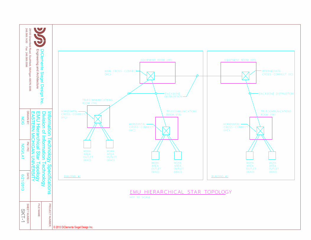
MAIN CROSS-CONNECT (MC)
TELECOMMUNICATIONS ROOM (TR)
EQUIPMENT ROOM (ER)
HORIZONTAL CROSS-CONNECT (HC)
TELECOMMUNICATIONS ROOM (TR)
WORK AREA OUTLET(WAO)
HORIZONTAL CROSS-CONNECT (HC)
BACKBONE DISTRUBTION
BUILDING #1
EQUIPMENT ROOM (ER)
INTERMEDIATE CROSS-CONNECT (IC)
HORIZONTAL CROSS-CONNECT (HC)
TELECOMMUNICATIONS ROOM (TR)
EMU HIERARCHICAL STAR TOPOLOGY
BUILDING #2
BACKBONE DISTRUBTION
NOT TO SCALE
WORK AREA OUTLET(WAO)
WORK AREA OUTLET(WAO)
WORK AREA OUTLET(WAO)
WORK AREA OUTLET(WAO)
WORK AREA OUTLET(WAO)
248.569.1430 Fax 248.569.009628105 G
reenfield Road, Southfield, M
ichigan 48076-3046
© 2013 DiClemente Siegel Design Inc.
DiC
lemente Siegel D
esign Inc.FILE N
AME:
SHEET N
UM
BER:
DATE:
PM / PIC
DR
AWN
BY:
PRO
JECT N
UM
BER:
Engineering and Architecture130504SK1
13-0504
6/21/2013N
DG
/LATN
DG
EASTERN
MIC
HIG
AN U
NIVER
SITYEM
U H
ierarchical Star TopologyD
ivision of Information Technology
Information Technology Specifications
SKT-1
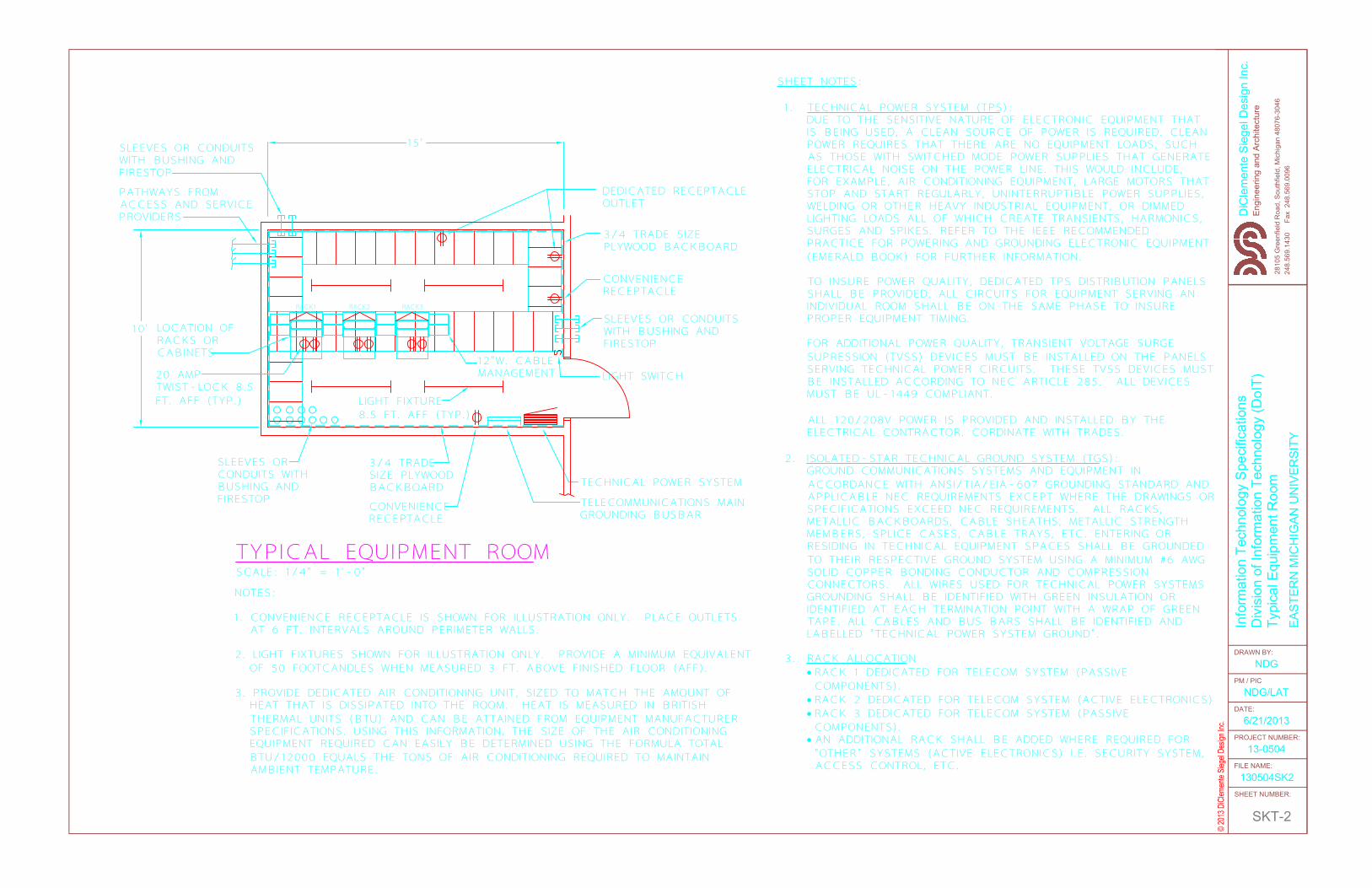
15'
10'
SLEEVES OR CONDUITS WITH BUSHING AND FIRESTOP
LOCATION OF RACKS OR CABINETS
3/4 TRADE SIZE PLYWOOD BACKBOARD
CONVENIENCE RECEPTACLE
LIGHT FIXTURE8.5 FT. AFF (TYP.)
SLEEVES OR CONDUITS WITH BUSHING AND FIRESTOP
PATHWAYS FROM ACCESS AND SERVICE PROVIDERS
TELECOMMUNICATIONS MAIN GROUNDING BUSBAR
SLEEVES OR CONDUITS WITH BUSHING AND FIRESTOP
TECHNICAL POWER SYSTEM
12"W. CABLE MANAGEMENT LIGHT SWITCH
DEDICATED RECEPTACLE OUTLET
3/4 TRADE SIZE PLYWOOD BACKBOARD
CONVENIENCE RECEPTACLE
RACK1 RACK2 RACK3
20 AMP TWIST-LOCK 8.5 FT. AFF (TYP.)
NOTES:
1. CONVENIENCE RECEPTACLE IS SHOWN FOR ILLUSTRATION ONLY. PLACE OUTLETSAT 6 FT. INTERVALS AROUND PERIMETER WALLS.
2. LIGHT FIXTURES SHOWN FOR ILLUSTRATION ONLY. PROVIDE A MINIMUM EQUIVALENT OF 50 FOOTCANDLES WHEN MEASURED 3 FT. ABOVE FINISHED FLOOR (AFF).
3. PROVIDE DEDICATED AIR CONDITIONING UNIT, SIZED TO MATCH THE AMOUNT OF HEAT THAT IS DISSIPATED INTO THE ROOM. HEAT IS MEASURED IN BRITISH THERMAL UNITS (BTU) AND CAN BE ATTAINED FROM EQUIPMENT MANUFACTURER SPECIFICATIONS. USING THIS INFORMATION, THE SIZE OF THE AIR CONDITIONING EQUIPMENT REQUIRED CAN EASILY BE DETERMINED USING THE FORMULA TOTAL BTU/12000 EQUALS THE TONS OF AIR CONDITIONING REQUIRED TO MAINTAIN AMBIENT TEMPATURE.
TYPICAL EQUIPMENT ROOMSCALE: 1/4" = 1'-0"
© 20
13 D
iClem
ente
Siege
l Des
ign In
c.
DiC
lem
ente
Sie
gel D
esig
n In
c.
248.
569.
1430
F
ax 2
48.5
69.0
096
2810
5 G
reen
field
Roa
d, S
outh
field
, Mic
higa
n 48
076-
3046
DRAWN BY:
PM / PIC
DATE:
PROJECT NUMBER:
FILE NAME:
SHEET NUMBER:
Engi
neer
ing
and
Arch
itect
ure
130504SK2
13-0504
6/21/2013
NDG/LAT
NDG
EAST
ERN
MIC
HIG
AN U
NIV
ERSI
TY
Typi
cal E
quip
men
t Roo
mD
ivis
ion
of In
form
atio
n Te
chno
logy
(DoI
T)In
form
atio
n Te
chno
logy
Spe
cific
atio
ns
SKT-2
SHEET NOTES:
1. TECHNICAL POWER SYSTEM (TPS):DUE TO THE SENSITIVE NATURE OF ELECTRONIC EQUIPMENT THAT IS BEING USED, A CLEAN SOURCE OF POWER IS REQUIRED. CLEAN POWER REQUIRES THAT THERE ARE NO EQUIPMENT LOADS, SUCH AS THOSE WITH SWITCHED MODE POWER SUPPLIES THAT GENERATE ELECTRICAL NOISE ON THE POWER LINE. THIS WOULD INCLUDE, FOR EXAMPLE, AIR CONDITIONING EQUIPMENT, LARGE MOTORS THAT STOP AND START REGULARLY, UNINTERRUPTIBLE POWER SUPPLIES, WELDING OR OTHER HEAVY INDUSTRIAL EQUIPMENT, OR DIMMED LIGHTING LOADS ALL OF WHICH CREATE TRANSIENTS, HARMONICS, SURGES AND SPIKES. REFER TO THE IEEE RECOMMENDED PRACTICE FOR POWERING AND GROUNDING ELECTRONIC EQUIPMENT (EMERALD BOOK) FOR FURTHER INFORMATION.
TO INSURE POWER QUALITY, DEDICATED TPS DISTRIBUTION PANELS SHALL BE PROVIDED, ALL CIRCUITS FOR EQUIPMENT SERVING AN INDIVIDUAL ROOM SHALL BE ON THE SAME PHASE TO INSURE PROPER EQUIPMENT TIMING.
FOR ADDITIONAL POWER QUALITY, TRANSIENT VOLTAGE SURGE SUPRESSION (TVSS) DEVICES MUST BE INSTALLED ON THE PANELS SERVING TECHNICAL POWER CIRCUITS. THESE TVSS DEVICES MUST BE INSTALLED ACCORDING TO NEC ARTICLE 285. ALL DEVICES MUST BE UL-1449 COMPLIANT.
ALL 120/208V POWER IS PROVIDED AND INSTALLED BY THE ELECTRICAL CONTRACTOR. CORDINATE WITH TRADES.
2. ISOLATED-STAR TECHNICAL GROUND SYSTEM (TGS):GROUND COMMUNICATIONS SYSTEMS AND EQUIPMENT IN ACCORDANCE WITH ANSI/TIA/EIA-607 GROUNDING STANDARD AND APPLICABLE NEC REQUIREMENTS EXCEPT WHERE THE DRAWINGS OR SPECIFICATIONS EXCEED NEC REQUIREMENTS. ALL RACKS, METALLIC BACKBOARDS, CABLE SHEATHS, METALLIC STRENGTH MEMBERS, SPLICE CASES, CABLE TRAYS, ETC. ENTERING OR RESIDING IN TECHNICAL EQUIPMENT SPACES SHALL BE GROUNDED TO THEIR RESPECTIVE GROUND SYSTEM USING A MINIMUM #6 AWG SOLID COPPER BONDING CONDUCTOR AND COMPRESSION CONNECTORS. ALL WIRES USED FOR TECHNICAL POWER SYSTEMS GROUNDING SHALL BE IDENTIFIED WITH GREEN INSULATION OR IDENTIFIED AT EACH TERMINATION POINT WITH A WRAP OF GREEN TAPE. ALL CABLES AND BUS BARS SHALL BE IDENTIFIED AND LABELLED "TECHNICAL POWER SYSTEM GROUND".
3. RACK ALLOCATION•RACK 1 DEDICATED FOR TELECOM SYSTEM (PASSIVE COMPONENTS).
•RACK 2 DEDICATED FOR TELECOM SYSTEM (ACTIVE ELECTRONICS)•RACK 3 DEDICATED FOR TELECOM SYSTEM (PASSIVE COMPONENTS).
• AN ADDITIONAL RACK SHALL BE ADDED WHERE REQUIRED FOR "OTHER" SYSTEMS (ACTIVE ELECTRONICS) I.E. SECURITY SYSTEM, ACCESS CONTROL, ETC.
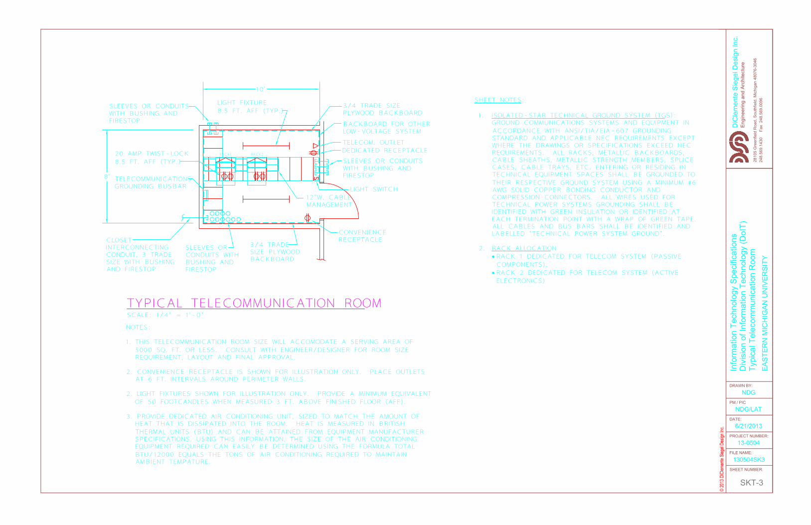
3/4 TRADE SIZE PLYWOOD BACKBOARD
8' TELECOMMUNICATIONS GROUNDING BUSBAR
CLOSET INTERCONNECTING CONDUIT, 3 TRADE SIZE WITH BUSHING AND FIRESTOP
SLEEVES OR CONDUITS WITH BUSHING AND FIRESTOP
20 AMP TWIST-LOCK 8.5 FT. AFF (TYP.)
SLEEVES OR CONDUITS WITH BUSHING AND FIRESTOP
SLEEVES OR CONDUITS WITH BUSHING AND FIRESTOP
CONVENIENCE RECEPTACLE
12"W. CABLE MANAGEMENT
TELECOM. OUTLETDEDICATED RECEPTACLE
BACKBOARD FOR OTHER LOW-VOLTAGE SYSTEM
3/4 TRADE SIZE PLYWOOD BACKBOARD
LIGHT FIXTURE8.5 FT. AFF (TYP.)
LIGHT SWITCH
RACK1 RACK2
10'
NOTES:
1. THIS TELECOMMUNICATION ROOM SIZE WILL ACCOMODATE A SERVING AREA OF 5000 SQ. FT. OR LESS. CONSULT WITH ENGINEER/DESIGNER FOR ROOM SIZE REQUIREMENT, LAYOUT AND FINAL APPROVAL.
2. CONVENIENCE RECEPTACLE IS SHOWN FOR ILLUSTRATION ONLY. PLACE OUTLETSAT 6 FT. INTERVALS AROUND PERIMETER WALLS.
2. LIGHT FIXTURES SHOWN FOR ILLUSTRATION ONLY. PROVIDE A MINIMUM EQUIVALENT OF 50 FOOTCANDLES WHEN MEASURED 3 FT. ABOVE FINISHED FLOOR (AFF).
3. PROVIDE DEDICATED AIR CONDITIONING UNIT, SIZED TO MATCH THE AMOUNT OF HEAT THAT IS DISSIPATED INTO THE ROOM. HEAT IS MEASURED IN BRITISH THERMAL UNITS (BTU) AND CAN BE ATTAINED FROM EQUIPMENT MANUFACTURER SPECIFICATIONS. USING THIS INFORMATION, THE SIZE OF THE AIR CONDITIONING EQUIPMENT REQUIRED CAN EASILY BE DETERMINED USING THE FORMULA TOTAL BTU/12000 EQUALS THE TONS OF AIR CONDITIONING REQUIRED TO MAINTAIN AMBIENT TEMPATURE.
TYPICAL TELECOMMUNICATION ROOMSCALE: 1/4" = 1'-0"
© 20
13 D
iClem
ente
Siege
l Des
ign In
c.
DiC
lem
ente
Sie
gel D
esig
n In
c.
248.
569.
1430
F
ax 2
48.5
69.0
096
2810
5 G
reen
field
Roa
d, S
outh
field
, Mic
higa
n 48
076-
3046
DRAWN BY:
PM / PIC
DATE:
PROJECT NUMBER:
FILE NAME:
SHEET NUMBER:
Engi
neer
ing
and
Arch
itect
ure
130504SK3
13-0504
6/21/2013
NDG/LAT
NDG
EAST
ERN
MIC
HIG
AN U
NIV
ERSI
TY
Typi
cal T
elec
omm
unic
atio
n R
oom
Div
isio
n of
Info
rmat
ion
Tech
nolo
gy (D
oIT)
Info
rmat
ion
Tech
nolo
gy S
peci
ficat
ions
SKT-3
SHEET NOTES:
1. ISOLATED-STAR TECHNICAL GROUND SYSTEM (TGS):GROUND COMMUNICATIONS SYSTEMS AND EQUIPMENT IN ACCORDANCE WITH ANSI/TIA/EIA-607 GROUNDING STANDARD AND APPLICABLE NEC REQUIREMENTS EXCEPT WHERE THE DRAWINGS OR SPECIFICATIONS EXCEED NEC REQUIREMENTS. ALL RACKS, METALLIC BACKBOARDS, CABLE SHEATHS, METALLIC STRENGTH MEMBERS, SPLICE CASES, CABLE TRAYS, ETC. ENTERING OR RESIDING IN TECHNICAL EQUIPMENT SPACES SHALL BE GROUNDED TO THEIR RESPECTIVE GROUND SYSTEM USING A MINIMUM #6 AWG SOLID COPPER BONDING CONDUCTOR AND COMPRESSION CONNECTORS. ALL WIRES USED FOR TECHNICAL POWER SYSTEMS GROUNDING SHALL BE IDENTIFIED WITH GREEN INSULATION OR IDENTIFIED AT EACH TERMINATION POINT WITH A WRAP OF GREEN TAPE. ALL CABLES AND BUS BARS SHALL BE IDENTIFIED AND LABELLED "TECHNICAL POWER SYSTEM GROUND".
2. RACK ALLOCATION•RACK 1 DEDICATED FOR TELECOM SYSTEM (PASSIVE COMPONENTS).
•RACK 2 DEDICATED FOR TELECOM SYSTEM (ACTIVE ELECTRONICS)

WORK AREA OUTLET (WAO) WALLPLATE(FLOORBOX SIMILAR)
232-A-01
NOT TO SCALE
1
2 3
A
HORIZONTAL CROSS-CONNECT (HC) PATCH PANELS
CAT 6
CAT 6
STAINLESS STEEL FACEPLACE - SIZE PER OUTLET BOX (SINGLE GANG, DOUBLE GANG, ETC.)
HORIZONTAL LINK IDENTIFIER HAVING FORMAT TR#-A-N, WHERE TR#=NUMERIC CHARACTER(S) IDENTIFYING THE ROOM NUMBER OF THE TELECOMMUNICATION ROOM (TR), A=ONE OR TWO ALPHA CHARACTERS UNIQUELY IDENTIFYING A SINGLE PATCH PANEL OR A GROUP OF PATCH PANELS WITH SEQUENTIALLY NUMBERED PORTS AND N=TWO TO FOUR NUMERIC CHARACTERS DESIGNATING THE PORT ON A PATCH PANEL IN THE TR.
OUTLET COLOR AS SPECIFIEDPROVIDE LABEL ON EACH CABLE AT JACK LOCATION AND PATCH PANEL. SIMILAR FOR EXISTING FLOORBOXES.
LABEL EACH RACK PATCH PANEL ON LEFT AND RIGHT SIDE.SUPPORT CABLES
EVERY 5' OR LESS
1 2 3
B
1 2 3
C
232-A-02
248.569.1430 Fax 248.569.009628105 G
reenfield Road, Southfield, M
ichigan 48076-3046
© 2013 DiClemente Siegel Design Inc.
DiC
lemente Siegel D
esign Inc.FILE N
AME:
SHEET N
UM
BER:
DATE:
PM / PIC
DR
AWN
BY:
PRO
JECT N
UM
BER:
Engineering and Architecture130504SK4
13-0504
6/21/2013N
DG
/LATN
DG
EASTERN
MIC
HIG
AN U
NIVER
SITYW
ork Area Outlet & Patch Panel Labeling
Division of Inform
ation TechnologyInform
ation Technology Specifications
SKT-4